© 2023 Roland Corporation
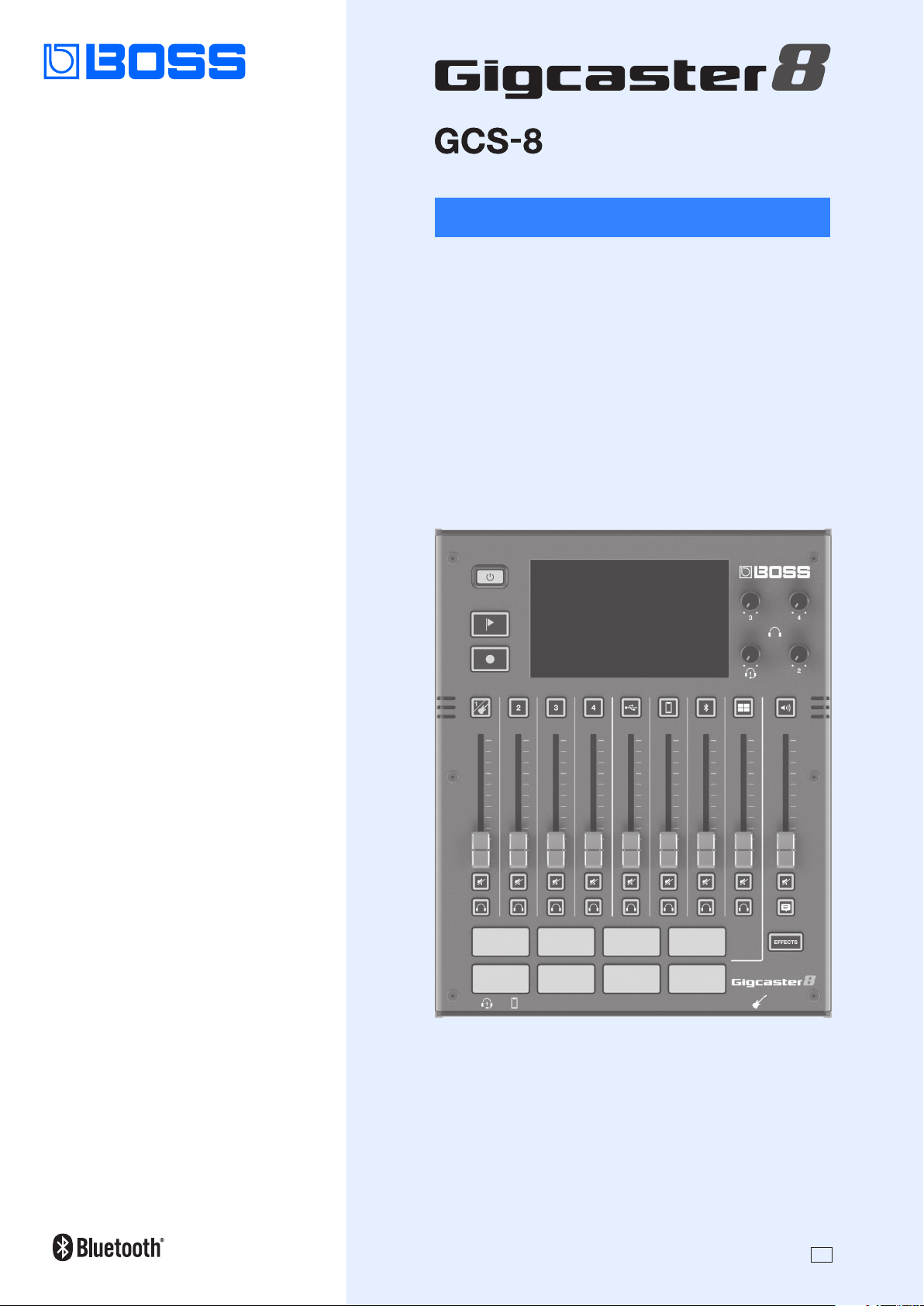
Reference Manual
01

2
Getting Ready .......................................... 3
Top Panel ..................................................3
Front Panel / Rear Panel .....................................4
Inserting a microSD Card ....................................5
Turning the Power On/O ...................................5
Setting the Date and Time ...................................5
Screen (Touch Panel) Operations .............................6
Conguring the Channels ...............................8
Channel 1–4 ................................................8
INPUT ....................................................8
EQ .......................................................8
EFFECTS ..................................................9
GENERAL .................................................9
USB Channel ............................................. 10
INPUT .................................................. 10
EQ ..................................................... 10
EFFECTS ................................................ 10
GENERAL ............................................... 11
MOBILE Channel .......................................... 12
INPUT .................................................. 12
EQ ..................................................... 13
EFFECTS ................................................ 13
GENERAL ............................................... 13
BLUETOOTH® Channel ..................................... 14
INPUT .................................................. 14
EQ ..................................................... 15
EFFECTS ................................................ 15
GENERAL ............................................... 15
SOUND PAD Channel ...................................... 16
EFFECTS ................................................ 16
GENERAL ............................................... 16
Editing the Eects ........................................ 17
Editing the Connection Order for Eects .................... 17
Saving an Eect Patch (Patch Write) ........................ 18
List of Patch Write Functions ............................... 18
Using the Tuner ........................................... 19
Using the Sound Pads ..................................20
Playing Back Audio ....................................... 20
Editing the Sound Pad Settings ............................ 20
Using the Eect Pads ..................................22
Selecting the Eect Congurations ......................... 22
Editing the Eect Pad Settings ............................. 22
Using a Footswitch and Expression Pedal ...............24
Specifying a Foot Controller ............................... 25
Footswitch/Expression Pedal Settings ...................... 25
Conguring Pad Link ...................................... 26
GA-FC Settings ........................................... 27
Recording .............................................28
Formatting a microSD Card ................................ 28
Selecting a Recording Method ............................. 28
Recording ................................................ 29
Playing Back Recorded Audio .............................. 29
Deleting Your Recorded Data .............................. 30
Backing Up Your Recorded Data ............................ 30
Output Settings .......................................31
MAIN OUT ................................................ 31
USB ...................................................... 32
USB MAIN ............................................... 32
USB MONITOR ........................................... 32
USB AUX IN. . . . . . . . . . . . . . . . . . . . . . . . . . . . . . . . . . . . . . . . . . . . . . 33
Talkback Settings (TALKBACK) ............................. 33
EFFECTS ................................................. 34
GENERAL ................................................. 34
Operating the MENU Screen ............................35
CHANNEL/OUTPUT/PAD/FOOT SW ......................... 35
SETUP ................................................... 35
Backing Up Data from the GCS-8 ........................... 36
Restoring the Factory Default Settings (Factory Reset) ....... 37
Error Message List .....................................38
Main Specications ....................................39
Contents

3
Getting Ready
1
2
3
4
7
8
9
5 6
9
1
[ Ā ] button
Turns the power on/o.
Long-press the button to turn the power o.
2
[
] (mark) button
When you press this button during recording, a mark is added
at that position.
Use the mark feature as a guide when editing on your
computer.
* The mark feature is enabled for multitrack recording. You can’t add
a mark when recording normally (two-channel mix).
Ø
“Recording” (p. 28)
[ ] button
Starts/pauses the recording.
* The data that you record is saved to the microSD card.
3
Display (Touch panel)
Access the various settings by touching the screen.
You can view a variety of information by operating the display.
4
[1]–[4] (Headphones 1–4) knobs
Adjusts the volume for headphones 1–4.
5
CHANNEL
[
]–[ ] (Channel edit) buttons
When these are on (lit up), the unit switches to the settings
screen for the selected channel.
Channel faders
These adjust the volume for each input channel.
[
] (Mute) buttons
Turns the mute feature on (lit) or o (unlit) for each input
channel.
[
] (Monitor) buttons
Turn this on (lit up) for a channel to output its sound to the
headphones jack.
This lets you hear the sound using your headphones.
6
OUTPUT
[
] (OUTPUT edit) button
Turn this on (lit up) to switch to the output (MAIN OUT,
headphones, etc.) settings screen.
OUTPUT fader
Adjusts the volume for the output (MAIN OUT, USB MAIN).
[ ] (Mute) button
Turns the output (MAIN OUT or USB MAIN) on (lit) or o (unlit).
[
] (Talkback) button
When this is on (lit up), the audio input from the built-in mic or
headset mic is output only to the PHONES jacks (talkback).
Use this to communicate only with the people who are
recording with you.
7
Pads 1–8
The functions of the sound pads/eect pads change
depending on whether the [EFFECTS] button is ON or OFF.
[EFFECTS ] button Function
O (Unlit)
Sound pads
Plays the audio assigned to each pad.
On (Lit)
Eect pads
Lets you use the settings for the eects
assigned to each pad.
8
[EFFECTS] button
When this is on (lit), pads 1–8 work as eect pads.
9
Built-in mic
Use this for recording acoustic instruments or when using
talkback.
Top Panel

4
Getting Ready
Front Panel / Rear Panel
* To prevent malfunction and equipment failure, always turn down the volume, and turn o all the units before making any connections.
Front panel
10 11 12
10
(Headphones 1) jack
Connect your headset or headphones here. Headsets can only
be used with headphones jack 1.
NOTE
Use a headset with a 3.5 mm CTIA-type mini plug (four-conductor).
* Pin arrangement for mini cable (four-conductor)
11
(Mobile) jack
Use this for inputting audio from a mobile device that’s
connected, such as a smartphone.
12
(Guitar) jack
Connect your guitar here.
The guitar audio is input to channel 1.
Rear panel
13
14
15
19
17
18
16
20
13
DC IN jack
Connect the included AC adaptor to this jack.
* Route the cord of the AC adaptor through the
grooves on the bottom of the unit as shown in
the illustration, to keep it in place.
* When turning the unit over, be careful so as to
protect the buttons and knobs from damage.
Also, handle the unit carefully; do not drop it.
14
ă (USB) port
Connect your computer or other device here to use this unit as
a USB audio interface, or for saving backups of your recorded
data or device settings (p. 30, p. 36).
Ø
See p. 32 for details on the USB output settings, and p. 35 for
the USB audio settings.
* Do not use a USB cable that is designed only for charging a device.
Charge-only cables cannot transmit data.
MEMO
This unit can be powered via the USB port.
A commercially available USB AC adaptor (5 V
/3 A or greater)
is required to power this unit.
15
Micro SD card slot
Insert a microSD card here.
L
R
GND
MIC

5
Getting Ready
16
– (Headphones 2–4) jacks
Connect your headphones here.
17
(Channel) 1–4 jacks
Use these jacks for audio input. Connect a mic, keyboard or
analog audio equipment here.
* About phantom power
You can supply phantom power (+48 V) from the Channel
1–4 jacks (XLR). Turn on phantom power when you’re using a
condenser microphone that requires phantom power.
Turn +48 V “ON” in the channel 1–4 settings screen.
* Pin arrangement for the
1–4 connectors (XLR/TRS)
2: HOT
1: GND
3: COLD
1: GND
2: HOT
3: COLD
TIP: HOT
RING: COLD
SLEEVE: GND
2: HOT
1: GND
3: COLD
1: GND
2: HOT
3: COLD
TIP: HOT
RING: COLD
SLEEVE: GND
18
FOOT SW jack
You can control various functions with a footswitch (FS-5U/
FS-6/FS-7), an expression pedal (FV-500H/FV-500L/EV-30 or
Roland EV-5) or a foot controller (GA-FC) that’s connected to
this unit.
* Use only the specied expression pedal. By connecting any other
expression pedals, you risk causing malfunction and/or damage
to the unit.
19
(MAIN OUT) L, R jacks
Connect these jacks to your amp, monitor speakers or mixer.
20
Ground terminal
Connect this to an external earth or ground if necessary.
Inserting a microSD Card
1. Insert the microSD card into
the Micro SD card slot until
you hear it click into place.
NOTE
When inserting a microSD card, take
care that it is oriented correctly, and
push it all the way in. Do not use
excessive force.
Removing a microSD card
2. Press the microSD card inward.
3. Grasp the microSD card and pull it toward yourself.
Turning the Power On/O
Before turning the unit on/o, always be sure to turn the volume
down. Even with the volume turned down, you might hear some
sound when switching the unit on/o. However, this is normal and
does not indicate a malfunction
Turning the Power On
1. Press the [Ā] button on this unit.
The power turns on, and the home screen
appears on the display.
2. Turn on the power of your
equipment in this order: connected
devices Ó amp.
Turning the Power O
1. Turn o the equipment in this order: amp Ó
connected devices.
2. Long-press the [Ā] button on this unit (for two
seconds).
A conrmation message appears.
3. Touch <YES>.
Setting the Date and Time
The date and time settings screen appears the rst time you turn
on this unit after purchase.
1. Touch the <–> <+> for YEAR/MONTH/DAY to set the
date.
2. Touch the <–> <+> for HOUR/MIN to set the time.
3. Touch <APPLY> to nish making the settings.
The date and time that you set is now applied, and the home
screen appears.
MEMO
From the menu screen, you can access <SETUP> Ó <GENERAL>
and select “DATE & TIME” to change these settings.

6
Getting Ready
Screen (Touch Panel) Operations
Home screen
The screen that appears after you turn on the power is called the “home screen”. On the home screen, you check the input/output levels
and recording status.
You can also touch the buttons shown on the screen to switch between input/output channels and settings screens for each function.
Date/time display
Touch this to switch to the date
and time settings screen.
Recording display
Shows the elapsed time
when recording.
MENU button
Accesses the MENU screen.
Level meter
Shows the levels for each channel.
These are the pre-mix levels before
the signal passes through the
input gain, EQ and eects.
The OUTPUT level meters show the
post-mix output levels.
TUNER button
Shows the TUNER screen.
Use this feature to tune your
instrument.
Phantom power: ON
Channels for which phantom
power is being used are marked
with a “Á”.
SD CARD button
Shows the SD CARD screen.
Use this to play back your recorded
data or to back up data to a
computer.
The view changes according to the input source set for
each channel.
¹ Touch the respective channel and the OUTPUT icon to open the window where you can switch between eect patches and view the edit
screens.
à Channel 1–4
Switches between eect patches. Switches to the edit screen for the
eect patch.
à USB–SOUND PAD channel, OUTPUT
Switches to the eect edit screen.
¹ Swipe left or right to show the sound pads (when the [EFFECTS] button is unlit) or the eect pads (when the [EFFECTS] button is lit).
Swipe left or right
Touch to switch to the settings
screen for each pad.
Switches between
banks.
Unlit
Lit

7
Getting Ready
MENU screen
Various settings on the MENU screen are shown here as a menu. To switch between screens, touch the menu item until the desired
settings screen appears.
Menu Explanation
CHANNEL
Congures the respective input
channels.
OUTPUT
Congures the output-related
settings, such as adjusting the
output audio from the MAIN OUT
jack and headphones jack.
PAD
Congures the sound pads/eect
pads.
Menu Explanation
FOOT SW
Species the function of the
footswitch or expression pedal
connected to the FOOT SW jack.
SETUP
Congures the overall system
settings for the GCS-8.
Main operations for each screen
Touch to select
Touch to turn on/o
Drag left/right to adjust
(Home) button
Returns to the home
screen.
(Return) button
Returns to the previous
screen.
Touch to switch between pages
Scroll bar
Drag up/down to scroll
Tap the value to the right of a slider
to switch between –/+ display.

8
Conguring the Channels
1. Press the [ ]–[ ] button on the top panel.
The settings screen for the channel corresponding to the
button you pressed appears.
INPUT
Selecting an input source
1. Touch <INPUT>.
2. Touch one of the inputs from <GTR> to <OFF> to
select an input source.
Input source Explanation
Guitar connected to the Guitar jack
* Only for channel 1
–
Mic, keyboard or audio equipment
connected to the channel 1–4 jacks
,
Select these when you want to use channels
1/2 or 3/4 as a stereo link.
When stereo link is turned on, the same
settings apply to both channels.
* Turning on stereo link also automatically
turns one of the channels o.
Built-in mic
Headset mic
* You can set either “INT MIC” or “HEADSET”
for just one channel.
O (no used)
Setting the input gain
3. Use the GAIN control to adjust the input gain.
Turning phantom power on/o
4. Turn the +48V setting to “ON” when you connect a
condenser mic that needs phantom power.
EQ
1. Touch <EQ>.
2. Tap the EQ button to turn it ON (the button lights up
green).
3. Adjust the tonal character of each frequency band.
* For details on the parameters, refer to “Parameter Guide” (Roland
website).
Channel 1–4

9
Conguring the Channels
EFFECTS
1. Touch <EFFECTS>.
2. Tap the EFFECTS button to turn it ON (the button
lights up green).
Selecting a category
3. Touch the EFFECTS CATEGORY button and then
select an eect category.
Category Explanation
GUITAR
Selects eect patches for guitars.
* Only for channel 1
SING
Selects eect patches for vocals.
* Only for channel 1, 2
TALK
Selects eect patches for conversations.
CONSOLE
This eect is shared between channels 1–4.
The parameters can be congured for each
channel.
* Edited settings are saved as-is.
Selecting eect patches
4. Use the PATCH control to select the eect patch you
want to use.
Patch Explanation
PRESET
These cannot be overwritten.
However, you can edit a preset patch and save it
as a user patch.
USER
These can be overwritten.
5. Adjusts the eect parameters.
* For details on the parameters, refer to “Parameter Guide” (Roland
website).
GENERAL
1. Touch <GENERAL>.
2. Set the parameters.
Parameter Explanation
USB AUX IN
Sets whether to input USB audio signals as
auxiliary input (AUX IN) for each channel (ON) or
not (OFF).
INSERT
Congures the input position for the USB audio
signal.
LEVEL
Congures the input level for the USB audio
signal.
REVERB
SEND
Sets the level of the signal sent to reverb from
each channel.
DYNAMICS
REMAIN
NOTE
This function is enabled when the eect category
is set to anything besides “GUITAR”.
When this is set to “ON”, ENHANCE/COMP/NS also
stay on, even when the EFFECTS button is OFF.
When DYNAMICS REMAIN is enabled
When the EFFECTS button is OFF,
this lights up blue.

10
Conguring the Channels
1. Press the [ ] button on the top panel.
INPUT
1. Touch <GAIN>.
2. Use the GAIN control to adjust the input gain.
EQ
1. Touch <EQ>.
2. Tap the EQ button to turn it ON (the button lights up
green).
3. Adjust the tonal character of each frequency band.
* For details on the parameters, refer to “Parameter Guide” (Roland
website).
EFFECTS
You can use eects exclusively for the USB channel.
1. Touch <EFFECTS>.
The eect edit screen appears.
2. Tap the EFFECTS button to turn it ON (the button
lights up green).
3. Set the parameters.
¹ For details on edit operations, refer to “Editing the Eects” (p. 17).
¹ For details on the parameters, refer to “Parameter Guide” (Roland
website).
MEMO
Edited settings are saved as-is.
USB Channel
This channel is used for USB audio signals from devices (such as a computer) that are connected to the ă (USB) port.
* When using this unit while AUDIO MODE (p. 35) is operating in multitrack (MTK-RECORD, MTK-STREAM), select the “CH USB” setting for the
computer’s USB audio.

11
Conguring the Channels
GENERAL
1. Touch <GENERAL>.
2. Set the parameters.
Ducking (DUCK)
When the audio from a performance or conversation is playing
(through channels 1–4), this function makes the sound of the
performance or conversation more prominent by making all
other sounds quieter.
This works by automatically bringing down the volume of the
music (such as background music) while the narrator is talking
or while other participants are having a chat.
Parameter Explanation
DUCK
Turns the ducking function on/o.
DUCK DEPTH
Sets how much the other sounds are attenuated
when ducking is active.
DUCK DECAY
Sets how long it takes for the levels to return to
their previous volume after ducking is activated.
Suppressing feedback (MIX MINUS)
This function returns the audio mix to your computer, without
the audio from the USB channel itself.
This helps to suppress feedback, such as when you’re having an
online conversation on your computer.
* The MIX MINUS function is enabled while AUDIO MODE (p. 35)
is operating in multitrack (MTK-RECORD, MTK-STREAM). The audio
signal is sent to the computer as USB MONITOR output (p. 32).
Parameter Explanation
MIX MINUS
Turns the MIX MINUS function on/o.
Others
Parameter Explanation
REVERB
SEND
Sets the level of the signal sent to reverb from
the USB channel.
DYNAMICS
REMAIN
When this is set to “ON”, ENHANCE/COMP/NS also
stay on, even when the EFFECTS button is OFF.
When DYNAMICS REMAIN is enabled
When the EFFECTS button is OFF,
this lights up blue.

12
Conguring the Channels
1. Press the [ ] button on the top panel.
INPUT
Selecting an input source
1. Touch <INPUT>.
2. Touch one of the inputs from <MOB> to <OFF> to
select an input source.
Input source Explanation
Smartphone or plug-in mic connected to the
Mobile jack
Built-in mic
Headset mic
* You can set either “INT MIC” or “HEADSET” for
just one channel.
O (no used)
Setting the input gain
3. Use the GAIN control to adjust the input gain.
Turning plug-in power on/o
4. To use a plug-in mic, set “PLUG-IN POWER” to “ON”.
MOBILE Channel
This channel is used for audio signals from devices (such as a smartphone) that are connected to the (Mobile) jack.

13
Conguring the Channels
EQ
1. Touch <EQ>.
2. Tap the EQ button to turn it ON (the button lights up
green).
3. Adjust the tonal character of each frequency band.
* For details on the parameters, refer to “Parameter Guide” (Roland
website).
EFFECTS
You can use eects exclusively for the MOBILE channel.
1. Touch <EFFECTS>.
The eect edit screen appears.
2. Tap the EFFECTS button to turn it ON (the button
lights up green).
3. Set the parameters.
¹ For details on edit operations, refer to “Editing the Eects” (p. 17).
¹ For details on the parameters, refer to “Parameter Guide” (Roland
website).
MEMO
Edited settings are saved as-is.
GENERAL
1. Touch <GENERAL>.
2. Set the parameters.
Ducking (DUCK)
When the audio from a performance or conversation is playing
(through channels 1–4), this function makes the sound of the
performance or conversation more prominent by making all
other sounds quieter.
This works by automatically bringing down the volume of the
music (such as background music) while the narrator is talking
or while other participants are having a chat.
Parameter Explanation
DUCK
Turns the ducking function on/o.
DUCK DEPTH
Sets how much the other sounds are attenuated
when ducking is active.
DUCK DECAY
Sets how long it takes for the levels to return to
their previous volume after ducking is activated.
Suppressing feedback (MIX MINUS)
This function returns the audio mix to the Mobile jack, without
the audio from the MOBILE channel itself.
This helps to suppress feedback, such as when you’re having a
conversation on your smartphone with wired connection.
Parameter Explanation
MIX MINUS
Turns the MIX MINUS function on/o.
Others
Parameter Explanation
TRRS
RETURN
Sets the volume when sending a mix sound to a
device connected to the Mobile jack.
REVERB
SEND
Sets the level of the signal sent to reverb from
the MOBILE channel.
DYNAMIC
REMAIN
When this is set to “ON”, ENHANCE/COMP/NS also
stay on, even when the EFFECTS button is OFF.
When DYNAMICS REMAIN is enabled
When the EFFECTS button is OFF,
this lights up blue.

14
Conguring the Channels
1. Press the [ ] button on the top panel.
INPUT
1. Touch <INPUT>.
Registering a Mobile Device (Pairing)
The example shown here uses the iPhone. For details, refer to
the owner’s manual of your mobile device.
2. Place the mobile device that you want to connect
near the GCS-8.
3. Touch <PAIR>.
4. Turn on the Bluetooth function of the mobile device.
5. Tap “GCS-8 Audio” that is shown in the Bluetooth
device screen of your mobile device.
“CONNECTING” Ó “PAIRING” Ó “WAITING” is shown while
connecting. When the connection has been established, the
name of the connected device is shown.
When pairing succeeds, “GCS-8 Audio” is added to the list of
“Paired Devices” on your mobile device.
If pairing is not performed within a certain amount of time,
the display changes to “DISCONNECTED”, and pairing standby
mode is canceled.
Connecting an already-paired mobile device
1. Touch <PAIR>.
2. Turn on the Bluetooth function of the mobile device.
MEMO
If the above step does not establish a connection, tap “GCS-8
Audio” that are shown in the “DEVICES” eld of the mobile device.
Setting the input gain
1. Use the GAIN control to adjust the input gain.
BLUETOOTH® Channel
This channel is used for audio signals from mobile devices (such as a smartphone) that are connected via Bluetooth.

15
Conguring the Channels
EQ
1. Touch <EQ>.
2. Tap the EQ button to turn it ON (the button lights up
green).
3. Adjust the tonal character of each frequency band.
* For details on the parameters, refer to “Parameter Guide” (Roland
website).
EFFECTS
You can use eects exclusively for the BLUETOOTH channel.
1. Touch <EFFECTS>.
The eect edit screen appears.
2. Tap the EFFECTS button to turn it ON (the button
lights up green).
3. Set the parameters.
¹ For details on edit operations, refer to “Editing the Eects” (p. 17).
¹ For details on the parameters, refer to “Parameter Guide” (Roland
website).
MEMO
Edited settings are saved as-is.
GENERAL
1. Touch <GENERAL>.
2. Set the parameters.
Ducking (DUCK)
When the audio from a performance or conversation is playing
(through channels 1–4), this function makes the sound of the
performance or conversation more prominent by making all
other sounds quieter.
This works by automatically bringing down the volume of the
music (such as background music) while the narrator is talking
or while other participants are having a chat.
Parameter Explanation
DUCK
Turns the ducking function on/o.
DUCK DEPTH
Sets how much the other sounds are attenuated
when ducking is active.
DUCK DECAY
Sets how long it takes for the levels to return to
their previous volume after ducking is activated.
Suppressing feedback (MIX MINUS)
This function returns the audio mix to your mobile device,
without the audio from the BLUETOOTH channel itself.
This helps to suppress feedback, such as when you’re having a
conversation on your smartphone.
Parameter Explanation
MIX MINUS
Turns the MIX MINUS function on/o.
Others
Parameter Explanation
REVERB SEND
Sets the level of the signal sent to reverb from
the BLUETOOTH channel.
DYNAMICS
REMAIN
When this is set to “ON”, ENHANCE/COMP/NS
also stay on, even when the EFFECTS button
is OFF.
When DYNAMICS REMAIN is enabled
When the EFFECTS button is OFF,
this lights up blue.
BLUETOOTH
SW
Turns the Bluetooth function on/o.

16
Conguring the Channels
1. Press the [ ] button on the top panel.
EFFECTS
You can use eects exclusively for the SOUND PAD channel.
1. Touch <EFFECTS>.
2. Tap the EFFECTS button to turn it ON (the button
lights up green).
3. In FX TYPE, select the eect you want to use.
4. Adjusts the eect parameters.
* For details on the parameters, refer to “Parameter Guide” (Roland
website).
MEMO
Edited settings are saved as-is.
GENERAL
1. Touch <GENERAL>.
2. Set the parameters.
Ducking (DUCK)
When the audio from a performance or conversation is playing
(through channels 1–4), this function makes the sound of the
performance or conversation more prominent by making all
other sounds quieter.
This works by automatically bringing down the volume of the
music (such as background music) while the narrator is talking
or while other participants are having a chat.
Parameter Explanation
DUCK
Turns the ducking function on/o.
DUCK DEPTH
Sets how much the other sounds are attenuated
when ducking is active.
DUCK DECAY
Sets how long it takes for the levels to return to
their previous volume after ducking is activated.
Others
Parameter Explanation
REVERB SEND
Sets the level of the signal sent to reverb from
the SOUND PAD channel.
SOUND PAD Channel
This channel is for the audio that’s assigned to the sound pads.
17
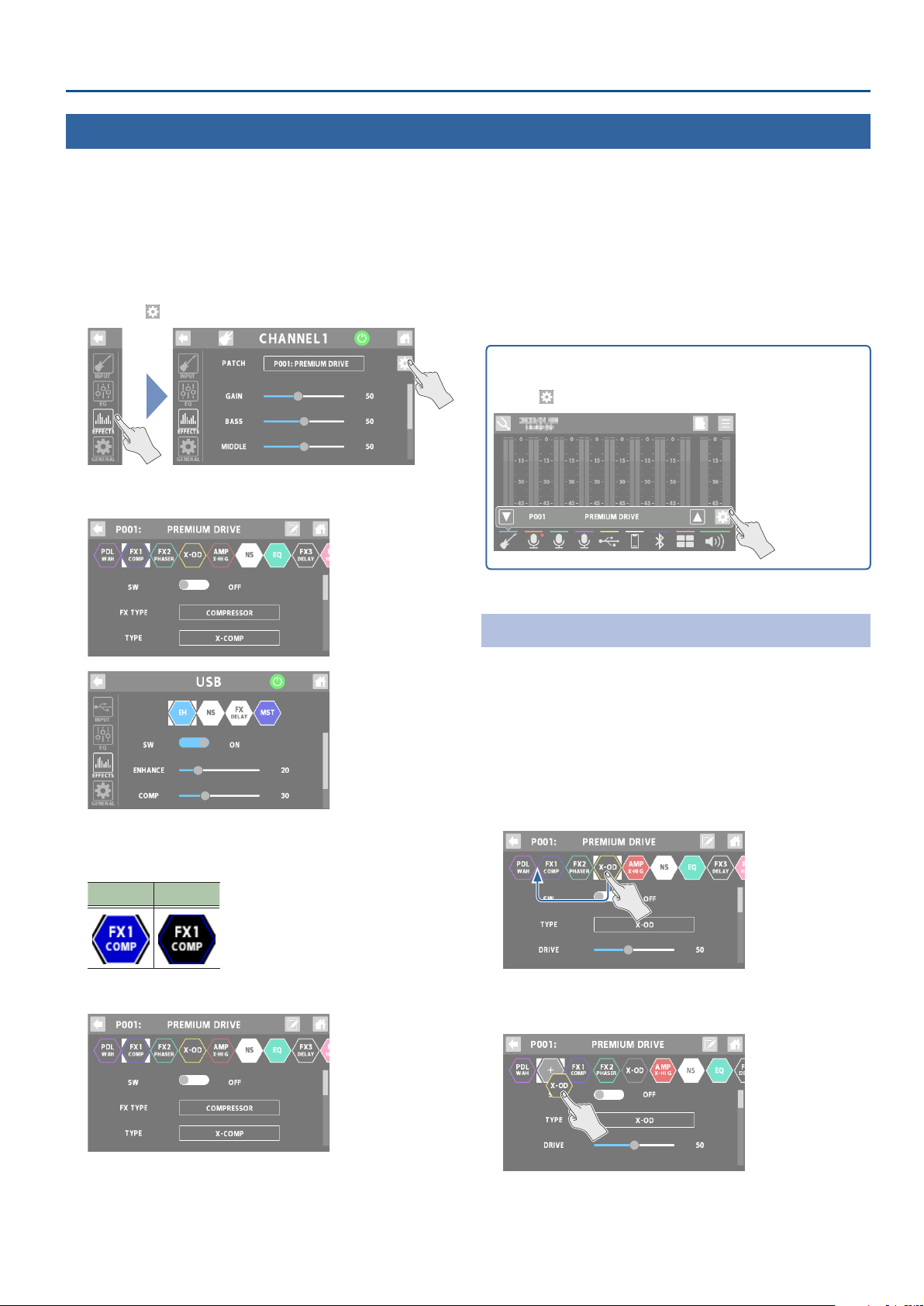
Conguring the Channels
1. Touch <EFFECTS>.
2. For channels 1–4: set “PATCH” to the eect patch you
want to edit.
* If the eect category is “CONSOLE”, this edits the CONSOLE eect.
3. Touch < >.
This shows the edit screen for the eect patch, or the EFFECT
EDIT screen.
4. Touch the icon of the eect you want to edit.
The eect toggles on/o each time you touch the icon.
On O
* Use “SW” to toggle the eects on/o.
The parameters of the selected eect are shown.
5. Edit the parameter’s value.
6. To save the eect patch you edited, follow the steps
to write the patch.
* When using the CONSOLE eect or the dedicated eects for the
channels from USB to SOUND PAD, you don’t need to write the
data. That’s because the settings you edit are saved as-is.
On the home screen, touch an icon corresponding to channels 1
through BLUETOOTH to open the window.
Touch <
> to display the eect edit screen.
Editing the Connection Order for Eects
When editing an eect patch belonging to the “GUITAR”
eect category, you can edit the order in which the eects are
connected.
1. Touch the icon of the eect whose position you
want to change, and drag it into the desired place in
the eect chain.
This example shows how to place the X-OD eect between
PDL and FX1.
2. When the “+” icon appears, release the nger you’re
using to drag the icon.
This places X-OD between PDL and FX1.
Editing the Eects
For channels 1–4, you can edit “eect patches”, and for the channels from USB through SOUND PAD, you can edit the dedicated eects for
each channel.
18
Conguring the Channels
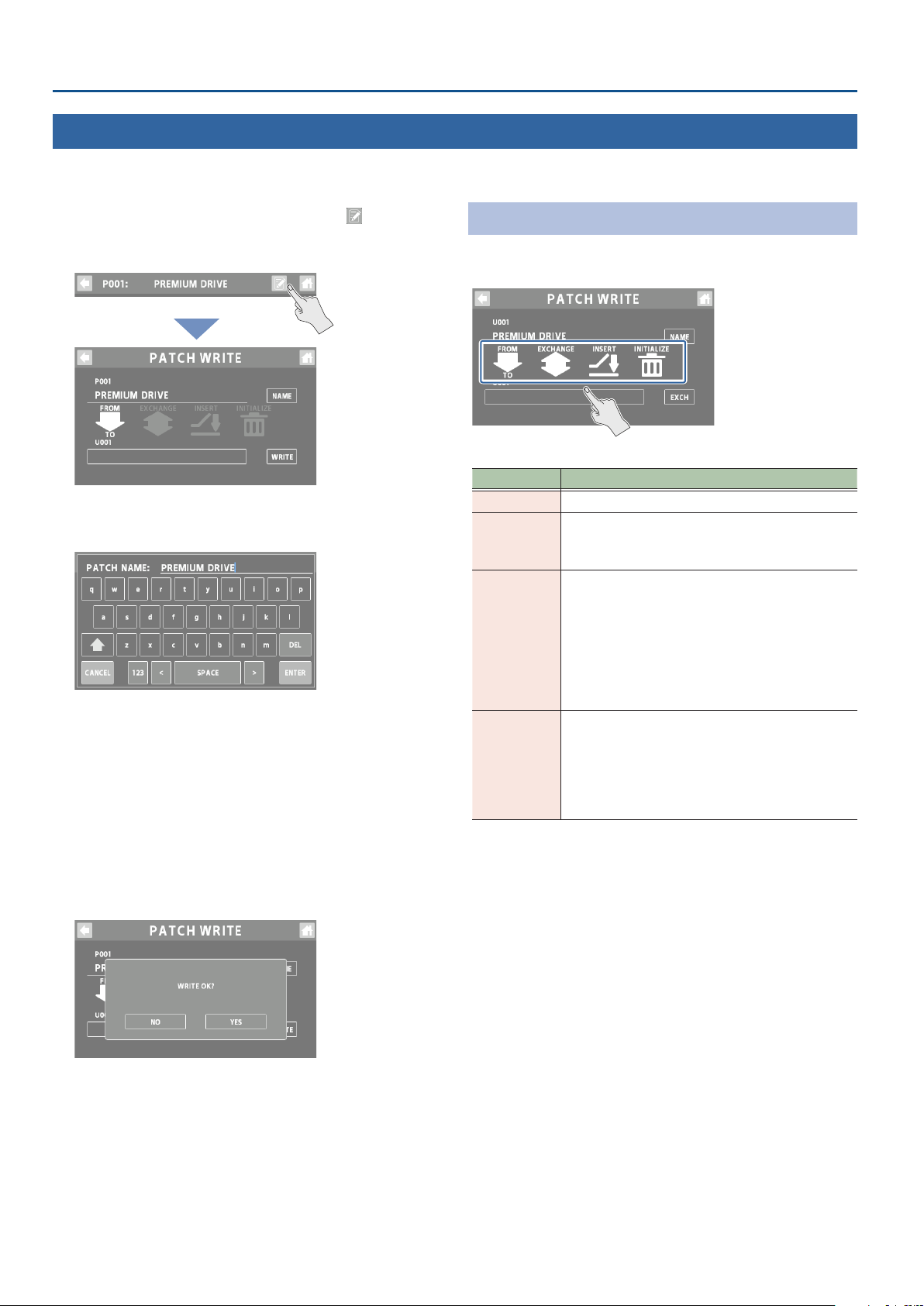
1. On the eect patch’s edit screen, touch <
> (write
button).
The PATCH WRITE screen appears.
2. Touch <NAME> to input a patch name.
¹ This step is unnecessary if you don’t need to change the patch name.
3. Touch <ENTER> when you’re nished entering the
patch name.
4. In the “TO” box, select the user patch where you
want to save the eect patch.
¹ You don’t have to do this if you want to overwrite the currently
selected user patch.
5. Touch <WRITE>.
A conrmation message appears.
* If you decide to cancel, touch <NO>.
6. Touch <YES>.
The user patch is saved.
* Make sure not turn to o the power while the “EXECUTING...”
message is shown.
List of Patch Write Functions
You can use the following functions on the PATCH WRITE screen.
Touch the screen to select a function.
Function Explanation
WRITE
Saves the user patch you created.
EXCHANGE
You can exchange the positions of two user patches.
Touch <EXCH> and then <YES> to exchange the
patches.
INSERT
You can insert a user patch into any position of the
user patches.
For example, if you insert memory U001 at U010,
memory U010 and subsequent memories are shifted
(renumbered) backward by one. (Memory U010
becomes U011.)
Touch <INSERT> and then <YES> to insert the
patches.
INITIALIZE
You can restore (initialize) each eect in an eect
patch to its standard settings.
This is useful when you want to create an eect
patch from scratch.
Touch <INIT> and then <YES> to initialize the
patches.
* Make sure not turn to o the power while the “EXECUTING...”
message is shown.
Saving an Eect Patch (Patch Write)
Here’s how to save the eect patches you edit as user patches.

19
Conguring the Channels
1. On the home screen, touch <
>
(TUNER button).
The TUNER screen appears.
Switching the meter display style
Swipe left or right on the TUNER screen to switch between the
display styles for the meter.
CENT display
The light moves further to the left the more the pitch of the
input note drops; as the pitch rises, the light moves further to
the right.
STREAM display
The movement of the light to the left or right indicates how far
the input note is out of tune.
The light streams to the left when the input pitch is at and to
the right when it is sharp.
The movement of the light slows down as the note approaches
the correct pitch, then stops when you reach the correct pitch.
2. Touch INPUT <CH1>–<CH4> to select the channel
used for tuning.
You can also select multiple channels.
3. Play a single note on your instrument, or sing a
single pitch.
The note name or string number for the note closest to the
tone being played appears in the display. The meter and
Tuning Guide show how far the note is from the correct pitch.
Pitch is sharp
Pitch is in tune
Pitch is at
4. Repeat step 3 while tuning your instrument or
adjusting your vocal pitch.
When the desired note name or string number appears in
the display, tune the instrument so that both Tuning Guide
indicators are lit and the pitch matches that displayed by the
meter.
Setting the reference pitch
1. Touch the <–> and <+> buttons to set the reference
pitch.
Value
435–445 Hz
Mute settings
You can mute the output of specic channels while you’re
using the tuner.
1. Touch MUTE <CH1>–<CH4> to select the channels
for which output is to be muted.
You can also select multiple channels.
Using the Tuner
You can use the GCS-8’s built-in tuner to tune your guitar or to check the pitch of the vocal input via mic or your instrument.

20
Using the Sound Pads
Playing Back Audio
1. Press the [EFFECTS] button to make it go dark.
This switches the pads to sound pad mode.
2. Press sound pads 1–8 to play back their respective
sounds.
1 2 3 4
5 6 7 8
Switching between banks
3. Long-press the [EFFECTS] button.
The sound pads 1–8 now switch between banks.
4. Press sound pads 1–8 to switch the bank.
1 2 3 4
5 6 7 8
Editing the Sound Pad Settings
You can edit the settings for the 64 sound pads (8 banks × 8).
1. On the home screen, touch <
>
(MENU button).
The MENU screen appears.
2. Touch <PAD>
Ó<SOUND>.
The SOUND PAD screen appears.
3. Touch < > and < > to select the bank.
4. Touch the pad for which you want to edit the
settings.
5. Edits the parameter’s value.
* The settings you edit are saved as-is.
In this mode, the pads play the audio assigned to each pad.
This lets you play background music, jingles, sound eects and so on at the optimum timing.
¹ You can assign up to 64 sounds (8 banks × 8) to the sound pads overall.
¹ Bank 1 is selected when you turn on this unit.

21
Using the Sound Pads
Parameter Explanation
FILE
Selects the audio le (.WAV) to assign to the pad.
MODE
1SHOT
One-shot playback
The audio le plays back only once and
then stops.
LOOP
Loop playback
The audio keeps playing back
repeatedly until you make it stop.
(TYPE)
MOMENT
Plays back audio while the pad is
pressed.
TOGGLE
Toggles between playback and stop
each time you press the pad.
PAUSE
Toggles between playback and pause
each time you press the pad.
The audio resumes playback from where
it last stopped.
To make the audio stop during playback,
long-press the pad.
REPLAY
Plays back from the beginning each
time you press the pad.
To make the audio stop during playback,
long-press the pad.
PLAY
When you press a pad to start playback
and then press a pad during playback,
the audio plays back to the end and
stops.
To make the audio stop during playback,
long-press the pad.
LEVEL
Sets the playback volume.
EFFECT
SEND
Sets whether to apply the eect that’s congured for
the SOUND PAD channel (ON) or not (OFF).
REVERSE
Sets whether to play back in reverse (ON) or in the
normal direction (OFF).
SPEED
Sets the audio playback speed.
This is specied as a ratio of the original.
PITCH
Shifts the audio playback pitch in semitones.
FINE
Fine-tunes the pitch of the audio playback.
FADE IN
Sets the fade-in time used when starting playback
with a fade-in.
When fade-in is not being used, set this to “OFF”.
FADE OUT
Sets the fade-out time used when the audio fades
out and stops.
When fade-out is not being used, set this to “OFF”.
CUT IN
When the audio is playing back on a pad for which
this is set to “ON”, all other audio sources (the
sound pads, channels 1–4 and the USB through
BLUETOOTH channels) are muted.
* Eects are not applied to the audio of pads for
which this is set to “ON”.
COLOR
Sets the color of the pad illumination.
MIDI CC
Sets the MIDI controller number (CC#) that’s
transmitted when the pad is pressed.
Set this to “OFF” if you don’t want to transmit this
data.
* For details on the parameters, refer to “Parameter Guide” (Roland
website).
When the [EFFECTS] button is unlit, swipe left or right on the home
screen to show the sound pads.
Touch the pad for which you want to edit the eects. This brings up
the edit screen.
You can use the dedicated app to import the WAV les to be
assigned to the sound pads.
For details on the dedicated app, see the BOSS website.
https://www.boss.info/support/

22
Using the Eect Pads
Selecting the Eect Congurations
1. Press the [EFFECTS] button to make it light up.
This switches the pads to eect pad mode.
2. Press eect pads 1–8 to turn the eects on.
1 2 3 4
5 6 7 8
Switching between banks
3. Long-press the [EFFECTS] button.
The eect pads 1–8 now switch between banks.
4. Press eect pads 1–8 to switch the bank.
1 2 3 4
5 6 7 8
Editing the Eect Pad Settings
You can edit the settings for the 64 eect pads (8 banks × 8).
1. On the home screen, touch <
>
(MENU button).
The MENU screen appears.
2. Touch <PAD>
Ó<EFFECTS>.
The EFFECTS PAD screen appears.
3. Touch < > and < > to select the bank.
4. Touch the pad for which you want to edit the
settings.
In this mode, you can use the settings for the eects assigned to each pad.
¹ You can assign up to 64 eect settings (8 banks × 8) to the eect pads overall.
¹ There are four groups (A–D) for each eect conguration. You can assign functions to each group and control each group at the same time.
¹ Bank 1 is selected when you turn on this unit.

23
Using the Eect Pads
5. Touch <A>–<D> to select a group.
6. Edits the parameter’s value.
* The settings you edit are saved as-is.
Parameter Explanation
CATEGORY
Select the category.
The functions you can select are dierent for each
category.
FUNCTION
Species the function that’s assigned to the pads.
Set this to “OFF” if you don’t want to specify a
function.
MODE
TOGGLE
This setting lets you toggle between
MIN and MAX values each time you
press a pad.
The pad lights up for the MAX value.
MOMENT
The MAX value is used while you are
pressing the pad.
The pad lights up for the MAX value.
MIN
Sets the lower limit (MIN) and the upper limit (MAX)
of the variable range for the parameter.
* The value changes depending on the function
assigned.
MAX
COLOR
Sets the color of the pad illumination.
* For details on the parameters, refer to “Parameter Guide” (Roland
website).
When the [EFFECTS] button is lit, swipe left or right on the home
screen to show the sound pads.
Touch the pad for which you want to edit the eects. This brings up
the edit screen.

24
Using a Footswitch and Expression Pedal
You can control various functions with a footswitch (FS-5U/FS-6/FS-7), an expression pedal (FV-500H/FV-500L/EV-30 or Roland EV-5) or a
foot controller (GA-FC) that’s connected to this unit.
Connecting footswitches
Connect one or more footswitches and set their mode/polarity switches by referring to the illustrations below.
FS-6
FS-7
CTL 2
FS-5U x 1
1/4” phone type
1/4” phone type
Stereo 1/4” phone type
Stereo 1/4” phone type
Stereo 1/4” phone type
Stereo 1/4” phone type
CTL 1CTL 2 CTL 1CTL 1
RINGTIP
Stereo 1/4” phone type
1/4” phone type x 2
CTL 1 CTL 2
FS-5U x 2
FS-5U
FS-6
Mode / Polarity switch
FS-7
Connecting GA-FC
You can also assign functions to control for expression pedals that are connected to a GA-FC.
* When connecting, make sure to use a stereo cable and connect the pedal to the FOOT SW jack.
PEDAL1 PEDAL3PEDAL2 PEDAL4 PEDAL6PEDAL5 EXP1 EXP2
FOOT CONTROL FX VOLUME

25
Using a Footswitch and Expression Pedal
Specifying a Foot Controller
Here’s how to specify which foot controller (footswitch, expression
pedal or GA-FC) is connected to the FOOT SW jack.
1. On the home screen, touch <
>
(MENU button).
The MENU screen appears.
2. Touch <FOOT SW>
Ó<GENERAL>.
3. In FOOT SW, specify the foot controller.
Value Explanation
CTL/EXP
Select this when connecting a footswitch or
expression pedal.
GA-FC
Select this when connecting a GA-FC.
Footswitch/Expression Pedal Settings
There are four groups (A–D) each for the footswitch (CTL 1,2)
and the expression pedal (EXP). You can assign functions to each
group and control them at the same time.
1. Select “CTL/EXP” for the “Specifying a Foot Controller”
operation.
2. Touch <CTL/EXP>.
3. Touch a control from <CTL1> to <EXP> to select the
footswitch or expression pedal for which you want
to set the function.
The setting screen appears.
4. Touch <A>–<D> to select a group.
5. Edits the parameter’s value.
* The settings you edit are saved as-is.

26
Using a Footswitch and Expression Pedal
CTL1, 2
Function Explanation
CATEGORY
Select the category.
The functions you can select are dierent for each
category.
FUNCTION
Species the function that’s assigned to the
footswitches.
Set this to “OFF” if you don’t want to specify a
function.
MODE
TOGGLE
This setting lets you toggle between
MIN and MAX values each time you
press a footswitch.
MOMENT
The MAX value is used while you are
pressing the footswitch.
MIN
Sets the lower limit (MIN) and the upper limit (MAX)
of the variable range for the parameter.
* The value changes depending on the function
assigned.
MAX
EXP
Function Explanation
CATEGORY
Select the category.
The functions you can select are dierent for each
category.
FUNCTION
Species the function that’s assigned to the
expression pedal.
Set this to “OFF” if you don’t want to specify a
function.
MIN
Sets the lower limit (MIN) and the upper limit (MAX)
of the variable range for the parameter.
The MIN setting is for when the pedal is fully raised,
and the MAX setting is for when the pedal is fully
advanced.
* The value changes depending on the function
assigned.
MAX
* For details on the parameters, refer to “Parameter Guide” (Roland
website).
Conguring Pad Link
Use pad link to control the functions that are assigned to pads 1–8
by operating the GA-FC.
You can control the sound pads and the eect pads.
NOTE
When using pad link, the settings for the function that’s assigned to
each switch on the GA-FC (PEDAL 1–6) are disabled, and you can only
control the functions assigned to pads 1–8.
The functions assigned to the expression pedals (EXP 1, 2) connected
to the GA-FC are enabled.
1. Select “GA-FC” for the “Specifying a Foot Controller”
(p. 25) operation.
“PAD LINK” is shown.
2. Toggle the PAD LINK setting on/o.
Value Explanation
ON
Controls the functions assigned to the sound
pads or to the eect pads 1–8 with the GA-FC.
OFF
Controls the functions assigned to each switch/
expression pedal on the GA-FC.
How the GA-FC switches correspond to the pads
Pad 1 Pad 2 Pad 3 Pad 4
Pad 5 Pad 6 Pad 7 Pad 8
Switches between pads 1–4/5–8
Switches between sound pads/eect pads

27
Using a Footswitch and Expression Pedal
1. Select “GA-FC” for the “Specifying a Foot Controller”
(p. 25) operation.
2. Touch <GA-FC>.
3. Touch a control from <PEDAL1> to <EXP2> to select
the switch or expression pedal for which you want
to set the function.
The setting screen appears.
4. Touch <A>–<D> to select a group.
5. Edits the parameter’s value.
* The settings you edit are saved as-is.
PEDAL1–6
Function Explanation
CATEGORY
Select the category.
The functions you can select are dierent for each
category.
FUNCTION
Species the function that’s assigned to the
switches.
Set this to “OFF” if you don’t want to specify a
function.
MODE
TOGGLE
This setting lets you toggle between
MIN and MAX values each time you
press a switch.
MOMENT
The MAX value is used while you are
pressing the switch.
MIN
Sets the lower limit (MIN) and the upper limit (MAX)
of the variable range for the parameter.
* The value changes depending on the function
assigned.
MAX
EXP1–2
Function Explanation
CATEGORY
Select the category.
The functions you can select are dierent for each
category.
FUNCTION
Species the function that’s assigned to the
expression pedals.
Set this to “OFF” if you don’t want to specify a
function.
MIN
Sets the lower limit (MIN) and the upper limit (MAX)
of the variable range for the parameter.
The MIN setting is for when the pedal is fully raised,
and the MAX setting is for when the pedal is fully
advanced.
* The value changes depending on the function
assigned.
MAX
* For details on the parameters, refer to “Parameter Guide” (Roland
website).
GA-FC Settings
There are four groups (A–D) each for the switches (PEDAL 1–6) and the expression pedals (EXP 1, 2). You can assign functions to each
group and control them at the same time.

28
Recording
Formatting a microSD Card
Before using a microSD card on the GCS-8, you must format the
microSD card.
* When you insert an unformatted microSD card, the message
“UNFORMATTED CARD” appears. Follow the onscreen instructions
to format the media.
1. On the home screen, touch <
>
(SD card button).
The SD CARD screen is shown.
2. Touch <FORMAT>.
A conrmation message appears.
* If you decide to cancel, touch <NO>.
3. Touch <YES>.
When formatting is complete, the message “COMPLETED”
appears.
NOTE
¹ Formatting the microSD card erases all data on the media.
¹ Never remove the microSD card while it is being formatted.
Selecting a Recording Method
When recording, you can either record the same two-channel mix
(stereo) that’s output from the
(MAIN OUT) jack, or record each
channel’s audio before the two-channel mix (multitrack).
Select the recording method that’s appropriate for the data you
want to record.
1. Select the recording method from the MULTITRACK
parameter on the SD CARD screen.
Value Explanation
OFF
Records a two-channel mix.
DIRECT
Records in multitrack.
The signal that’s adjusted by the input gain
(without EQ or eects applied) is recorded.
PRE FADER
Records in multitrack.
The signal before being adjusted by each
channel fader is recorded.
Use this when you want to adjust the mix
balance of the recorded data using your DAW or
other software.
POST FADER
Records in multitrack.
The signal for which the mix balance is adjusted
by each channel fader is recorded.
Now, let’s record your guitar performance or conversations.
NOTE
¹ A microSD card (commercially available) is required for recording.
¹ Depending on the manufacturer or type of microSD card, some cards might not work correctly for recording or playback on the GCS-8.
¹ Never turn o the power or remove the microSD card during recording or playback.

29
Recording
Recording
1. Press the [ ] button.
The button lights up red, and recording begins.
The elapsed recording time is shown on the home screen.
¹ When you press the [ ] button while recording, the recording is
paused.
¹ When paused, press the [
] button to resume recording (the button
lights up red).
Adding marks
You can add a “mark” to the recorded data by pressing the [ ]
button while recording. You can use marks when editing the
recorded data on your DAW or other software.
2. To nish recording, long-press the [ ] button.
The button’s LED lights up dimly, and recording ends.
Playing Back Recorded Audio
1. On the SD CARD screen, touch <PLAYBACK>.
The PLAYBACK screen appears.
2. Touch < PLAY>.
The recorded audio is played back.
You can check the two-channel mix of the recorded audio from
the PLAYBACK screen.
1
3
4 7
5 6
2
8
Display Explanation
1
File name
The recorded data (audio le).
Touch this to view a list of audio les.
2
Mark
Shows the mark locations.
3
Playback
position
Shows the playback position.
Drag the Ç to move the playback position.
4
PREV
When you touch this while the audio is
stopped, the transport moves back to the
previous mark.
5
REW
Rewind
6
PLAY
Toggles between play/stop with each touch.
This lights up green during playback.
7
FWD
Fast-forward
8
NEXT
Touch this while the audio is playing back or
stopped to advance to the next mark.
When playing back previously recorded audio
Touch a lename, and then touch the audio le to play back
from the list of audio les.

30
Recording
Deleting Your Recorded Data
1. On the PLAYBACK screen, select the audio le you
want to delete.
2. Touch < >.
A conrmation message appears.
* If you decide to cancel, touch <NO>.
3. Touch <YES>.
When deleting is complete, the message “COMPLETED”
appears.
CARD REMAIN shows how much free storage (available recording
time) left on the microSD card.
Backing Up Your Recorded Data
1. On the SD CARD screen, touch <BACKUP>.
The message “CONNECTING...” is shown.
2. Use a USB cable to connect the GCS-8’s USB port to
your computer’s USB port.
When a connection with the computer is established, the
message “CONNECTED” appears.
3. Open the GCS-8_EXT drive.
Windows
In “PC”, open “GCS-8_EXT”.
macOS
On the desktop, open the “GCS-8”_EXT” icon.
4. Copy the audio le (.WAV) that you want to back up
to your computer.
5. Touch <DISCONNECT> to eject the GCS-8_EXT drive.
The message “DISCONNECTING...” is shown.
* You can also use the computer to eject the GCS-8_EXT drive.
Windows
In the lower right of your screen, click the [ ] and then the [
] icon, and then click “GCS-8_EXT”.
macOS
Drag the “GCS-8_EXT” icon to the trash (“Eject” icon).
You can use the dedicated app to convert the audio le format.
For details on the dedicated app, see the BOSS website.
https://www.boss.info/support/

31
Output Settings
1. Press the [ ] button on the top panel.
The OUTPUT screen is shown.
2. Touch one of the buttons from <MAINOUT> to
<GENERAL> to select the item to set.
When touching <USB>
3. Touch one of the buttons from <MAIN> to <AUX IN>
to select the item to set.
MAIN OUT
Here’s how to congure the MAIN OUT output settings.
EQ
1. Touch <EQ>.
2. Tap the EQ button to turn it ON (the button lights up
green).
3. Adjust the tonal character of each frequency band.
* For details on the parameters, refer to “Parameter Guide” (Roland
website).
GENERAL
1. Touch <GENERAL>.
2. Set the parameters.
Parameter Explanation
LEVEL
Sets the signal output level.

32
Output Settings
USB MAIN
This is the main output for USB. The same audio as the audio
output from the MAIN OUT jacks is outputted.
EQ
1. Touch <EQ>.
2. Tap the EQ button to turn it ON (the button lights up
green).
3. Adjust the tonal character of each frequency band.
* For details on the parameters, refer to “Parameter Guide” (Roland
website).
GENERAL
1. Touch <GENERAL>.
2. Set the parameters.
Parameter Explanation
LEVEL
Sets the signal output level.
MONO MIX
Switches the signal output from USB to mono.
USB MONITOR
This is the monitor output for USB. The same signal is output as
that which is output from the headphones 1–4 jacks.
You can also use your computer to listen to the audio that you can
hear from the headphone jacks of the GCS-8, by specifying the
channel for conversation or chats.
EQ
1. Touch <EQ>.
2. Tap the EQ button to turn it ON (the button lights up
green).
3. Adjust the tonal character of each frequency band.
* For details on the parameters, refer to “Parameter Guide” (Roland
website).
GENERAL
1. Touch <GENERAL>.
2. Set the parameters.
Parameter Explanation
LEVEL
Sets the signal output level.
MONO MIX
Switches the signal output from USB to mono.
USB
Here’s how to congure the USB output settings.

33
Output Settings
USB AUX IN
This is the USB input that’s mixed just before the OUTPUT fader.
Use this when you want to check the sound without eects, such
as when you’re editing sounds or music on your computer.
1. Set the parameters.
Parameter Explanation
LEVEL
Sets the signal input level.
Talkback Settings (TALKBACK)
Here’s how to congure the settings for using talkback.
1. Touch the TALKBACK button or press the [ ]
(talkback) button on the top panel to turn it on
(lights up green).
2. Set the parameters.
Selecting the talkback channel (CHANNEL)
Select the channel for the talkback audio.
You can select multiple channels.
Parameter Value
CHANNEL
CH1–4, USB, MOBILE, BLUETOOTH
Selecting the input source for talkback only
Set the input source used only for talkback.
You can use a mic or headset mic exclusively for talkback, even
if the built-in mic or a headset mic is not set for the channel’s
input source.
Parameter Explanation
AUX IN
Selects the input source (built-in mic or headset
mic) used exclusively for talkback.
Set this to “OFF” if you don’t want to specify a
function.
AUX GAIN
Adjusts the input gain for when AUX IN is used.
Others
Parameter Explanation
THRU OUT
Sets the MAIN OUT output level for the channels
not used for talkback.
The channels that aren’t used for talkback can be
used to play background music.
When this is “OFF”, all output audio from MAIN
OUT is muted when talkback is used.
OUTPUT
Sets the output destination for the talkback
audio.
34
Output Settings
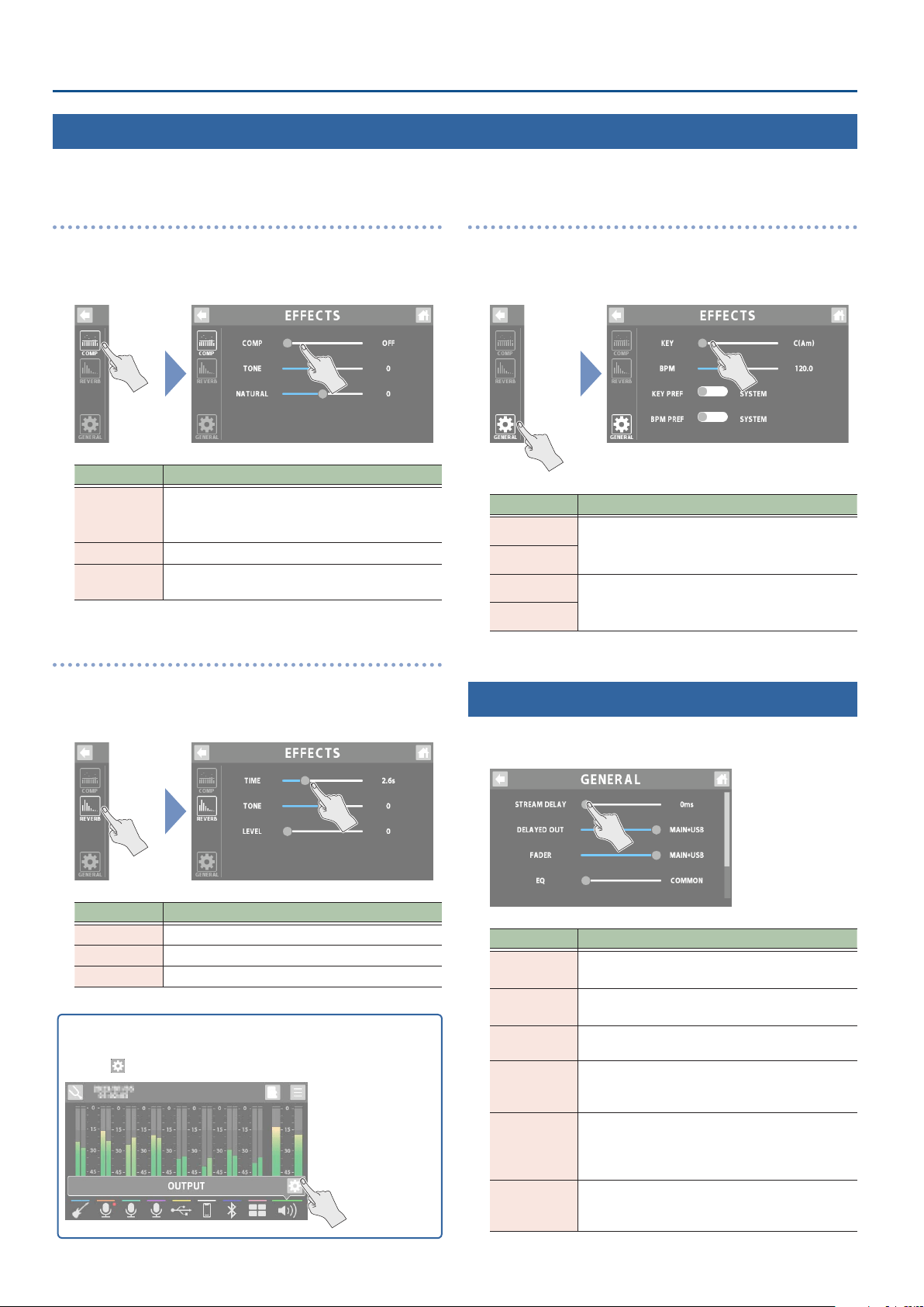
COMP
1. Touch <COMP>.
2. Set the parameters.
Parameter Explanation
COMP
Sets the compressor depth.
When this is “OFF”, no compressor eect is
applied.
TONE
Adjusts the tonal character of the compressor.
NATURAL
Larger values make the compressor take eect in
a more natural way.
REVERB
1. Touch <REVERB>.
2. Set the parameters.
Parameter Explanation
TIME
Adjusts the length (time) of reverberation.
TONE
Adjusts the tonal character of the reverb.
LEVEL
Adjusts the volume of the reverb sound.
On the home screen, touch an icon corresponding to OUTPUT to
open the window.
Touch <
> to display the EFFECTS screen.
GENERAL
1. Touch <GENERAL>.
2. Set the parameters.
Parameter Explanation
KEY
A common KEY and BPM are set for the eect
patches (channels 1–4) and for the dedicated
eects (USB through BLUETOOTH channels).
BPM
KEY PREF
Selects whether to set the KEY and BPM as
GENERAL (SYSTEM) settings, or whether to use
the eect patch settings for CH1.
BPM PRF
GENERAL
1. Set the parameters.
Parameter Explanation
STREAM
DELAY
Use this to adjust any delays that occur between
the video and audio.
DELAYED
OUT
Sets the output destination for the audio that’s
adjusted in STREAM DELAY.
FADER
Sets the output for which volume adjustment is
enabled for the OUTPUT fader.
EQ
Determines whether to use the same EQ settings
for the MAIN OUT and headphones 1–4 jacks, or
whether to set them individually.
MONITOR
Sets whether to enable or disable volume
adjustment of each channel fader, for the audio
that’s output from the headphones jacks 1–4 and
USB MONITOR.
HEDSET MIX
MINUS
Sets whether to return the input sound from the
headset mic to headphones jack 1 (ON) or not
(OFF).
EFFECTS
This shows you how to apply eects to the output audio.

35
Operating the MENU Screen
1. On the home screen, touch <
>
(MENU button).
The MENU screen appears.
2. Touch a button from <CHANNEL> to <SETUP> to
select a menu item.
3. To switch between screens, touch the menu item
until the desired settings screen appears.
4. Set the parameters.
CHANNEL/OUTPUT/PAD/FOOT SW
Item Explanation
CHANNEL
Sets the respective input channels.
This is the same as “Conguring the Channels” (p. 8).
OUTPUT
Congures the output-related settings.
This is the same as “Output Settings” (p. 31).
PAD
Congures the sound pads/eect pads.
This is the same as “Editing the Sound Pad Settings” (p.
20) and “Editing the Eect Pad Settings” (p. 22).
FOOT SW
Species the function of the footswitch, expression
pedal or GA-FC connected to the FOOT SW jack.
This is the same as “Using a Footswitch and Expression
Pedal” (p. 24).
SETUP
These are the overall system settings for the GCS-8.
DISPLAY
Parameter Explanation
BRIGHTNESS
LCD
Adjusts the brightness of the display.
LED ON
Adjusts the brightness of the buttons and pads when
the buttons and pads are on.
LED OFF
Adjusts the brightness of the buttons and pads when
the buttons and pads are o.
EDIT SW
Sets how the channel edit buttons and the OUTPUT
edit button lights up.
CLIP LEVEL
Sets the clip display level for the level meter shown
on the home screen.
SD CARD
This is the same as “Recording” (p. 28).
USB
Parameter Explanation
AUDIO MODE
This species the operating mode for the audio.
2 MIX
Operates with stereo input/output.
This uses the standard driver of the
respective OS.
MTK-
RECORD
Operates with multitrack input/output.
This uses a dedicated driver.
This is a mode for recording that lets you
switch between dierent sampling rates.
Useful when recording with a DAW or
other software.
MTK-
STREAM
Operates with multitrack input/output.
This uses a dedicated driver.
When using this unit with a Mac, this
mode lets you select each channel
individually.
This is handy when using apps for
conversation and the like.
MULTITRACK
When outputting in multitrack, this sets which
signal to output.
MIDI CH
Species the transmit/receive channel for MIDI
data.
GENERAL
Parameter Explanation
VERSION
Displays the version of the system program.
DATE & TIME
Sets the date and time.
BACKUP
Backs up the GCS-8’s data to your computer.
FACTORY
RESET
Returns the unit to its factory defaults.
Various settings on the MENU screen are shown here as a menu. To switch between screens, touch the menu item until the desired
settings screen appears.

36
Operating the MENU Screen
1. On the MENU screen, touch <SETUP>Ó<GENERAL>.
The GENERAL screen appears.
2. For the BACKUP, touch <EXECUTE>.
A conrmation message appears.
3. Touch <YES>.
The message “CONNECTING...” is shown.
4. Use a USB cable to connect the GCS-8’s USB port to
your computer’s USB port.
When a connection with the computer is established, the
message “CONNECTED” appears.
5. Open the GCS-8_INT drive.
Windows
In “PC”, open “GCS-8_INT”.
macOS
On the desktop, open the “GCS-8_INT” icon.
6. Back-up or recover the data.
Backup
Copy the “ROLAND” folder and the “GCS-8_BAK.BIN” le that are
on the GCS-8_INT drive to your computer.
Recover
* When you execute this operation, the memory currently saved in
the GCS-8 disappears. Back up in advance.
In the GCS-8_INT drive, delete the “ROLAND”folder and
“GCS-8_BAK.BIN” le, and then copy the backed-up “ROLAND”
folder and “GCS-8_BAK.BIN” le from the computer into the
GCS-8_INT drive.
NOTE
Do not delete the folders in the GCS-8_INT drive other than
when executing the recovery operation.
7. Touch <DISCONNECT> to eject the GCS-8_INT drive.
The message “DISCONNECTING...” is shown.
* You can also use the computer to eject the GCS-8_INT drive.
Windows
In the lower right of your screen, click the [ ] and then the [ ]
icon, and then click “GCS-8_INT”.
macOS
Drag the “GCS-8_INT” icon to the trash (“Eject” icon).
You can use the dedicated app to back up the data from the GCS-8.
For details on the dedicated app, see the BOSS website.
https://www.boss.info/support/
Backing Up Data from the GCS-8
Backs up the GCS-8’s data to your computer.

37
Operating the MENU Screen
1. On the MENU screen, touch <SETUP>Ó<GENERAL>.
The GENERAL screen appears.
2. For the FACTORY RESET, touch <EXECUTE>.
The FACTORY RESET screen appears.
3. Select the settings to restore.
Right after the display switches to the FACTORY RESET screen,
all the settings are selected.
Parameter Explanation
MIXER
Channel 1–4 settings
USB–SOUND PAD channel settings
OUTPUT settings
Sound pad settings
Eect pad settings
Footswitch settings
Expression pedal settings
GA-FC settings
EFFECT PATCH
GUITAR
Eect patches for which the EFFECTS CATEGORY
is set to “GUITAR”
SING
Eect patches for which the EFFECTS CATEGORY
is set to “SING”
TALK
Eect patches for which the EFFECTS CATEGORY
is set to “TALK”
4. Touch <EXECUTE>.
A conrmation message appears.
* If you decide to cancel, touch <NO>.
5. Touch <YES>.
The factory reset is executed.
* Make sure not turn to o the power while the “EXECUTING...”
message is shown.
Restoring the Factory Default Settings (Factory Reset)
You can restore all of the settings to their factory-set values, and you can also specify certain items to be reset.
* When you execute “Factory Reset”, the settings you made are lost. Back up any necessary data to your computer.

38
Error Message List
Message Meaning Action
microSD card
CARD FULL
The microSD card has run out of free storage space. Delete any unnecessary WAV les.
CARD TOO BUSY
When recording or playing back, data cannot be
written/read fast enough from the microSD card.
Use a dierent microSD card.
NO CARD
No microSD card is inserted. Insert a microSD card.
PROTECTED CARD
The unit is trying to record to a protected microSD card. Unlock the write-protect switch on the microSD card.
UNFORMATTED CARD
A microSD card is inserted that hasn’t been formatted
on the GCS-8.
Follow the onscreen messages to format the microSD
card.
UNSUPPORTED CARD
The microSD card can’t be used on the GCS-8. Use a dierent microSD card.
Recording, Playback
NOW PLAYING
You can’t perform the operation while the unit is
playing back.
–
NOW RECORDING
You can’t perform the operation while the unit is
recording.
The remaining card
capacity is low
There are less than ve minutes of recording time left.
Others
INSUFFICIENT USB BUS
POWER.
CHANGE THE USB PORT OR
USE PSD ADAPTOR.
Not enough power can be supplied to the USB port.
Connect a commercially available USB AC adaptor (at
least 5 V /3 A).
SETUP DATE & TIME?
This is shown when the internal clock has been reset if
the unit has not been powered up for a specic period
of time.
Touch <YES> to congure the date and time settings
(p. 5).
GIGCASTER APP NOT
FOUND
The dedicated app is not connected.
–
FILE NOT EXIST
There is no selectable WAV le on the sound pad
settings screen (p. 20) or on the PLAYBACK screen (p.
29).
UNSUPPORTED FILE
A WAV le that’s not supported by the GCS-8 has been
selected on the sound pad settings screen (p. 20) or
on the PLAYBACK screen (p. 29).
PROTECTED FILE
You are trying to delete or overwrite a protected WAV
le.
FILE SYSTEM ERROR
Data cannot be correctly written to or read from the
microSD card or internal memory.
Use the factory reset function (p. 37) to restore the
GCS-8 to its factory settings.
If the problem is not resolved even after a factory
reset, contact the dealer where you purchased this
unit, or contact Roland support.
DATA DAMAGED
The data may have been damaged.
SYSTEM ERROR OCCURRED
PLEASE REBOOT
An unknown error occurred.

39
Main Specications
Sample Rate
48 kHz
AD Conversion
24 bits
DA Conversion
32 bits
Processing
32-bit oating point
USB Audio
Input: 20 ch
Input: 14 ch
Bluetooth
A2DP, HFP
Recording
Data Format: BWF (48 kHz, 32-bit oat)
Storage: microSD card (sold separately)
Sound Pad
Data Format: WAV (48 kHz, 16-bit linear)
Storage: internal storage (16 GB)
Eect Patches
GUITAR: 200 (User) + 100 (Preset)
SING: 200 (User) + 30 (Preset)
TALK: 200 (User) + 30 (Preset)
Number of Eects
GUITAR:
1 ch (DISTORTION, PREAMP, EQ, NS, PEDAL FX, FX1, FX2, FX3, DELAY/REVERB)
SING: 2 ch (COMP, ENHANCE, DESS, EQ, NS, PITCH CORRECT, HARMONY, FX1, FX2, FX3, DELAY/REVERB)
TALK: 4 ch (COMP, ENHANCE, DESS, EQ, NS, FX1, FX2)
CONSOLE: 7 ch (COMP, ENHANCE, DESS, NS, FX)
FX: 1 ch (for SOUND PAD)
OUTPUT: COMP, REVERB
Nominal Input Level
(Adjustable)
GUITAR INPUT: -10 dBu
INPUT 1–4 (XLR type): -40 dBu
INPUT 1–4 (TRS type): -10 dBu
MOBILE IN: -20 dBu
Input Impedance
GUITAR INPUT: 1 MΩ
INPUT 1–4 (XLR type): 5.6 kΩ
INPUT 1–4 (TRS type): 27 kΩ
MOBILE IN: 22 kΩ
Nominal Output Level
MAIN OUT L, R: -10 dBu
Output Impedance
MAIN OUT L, R: 1 kΩ
PHONES 1–4: 47 Ω
Recommended Load
Impedance
MAIN OUT L, R: 10 kΩ or greater
Display
Color Graphic LCD (480 x 272 dots), Touch screen
Controls
Channel edit button (CH 1–4, USB, MOBILE, BLUETOOTH, SOUND PAD)
OUTPUT edit button
Mute button (CH 1–4, USB, MOBILE, BLUETOOTH, SOUND PAD)
OUTPUT Mute button
Monitor button (CH 1–4, USB, MOBILE, BLUETOOTH, SOUND PAD)
Talkback button
Rec button
Mark button
EFFECTS button
Pads 1–8
Channel fader (CH 1–4, USB, MOBILE, BLUETOOTH, SOUND PAD)
OUTPUT fader
Headphones 1–4 knobs

40
Main Specications
Connectors
Guitar jack: 1/4-inch phone type
Channel 1–4 jacks: Combo type (XLR, 1/4-inch TRS phone), balanced
Mobile jack: Stereo miniature phone type (CTIA)
MAIN OUT (L, R) jacks: 1/4-inch phone type
Headphones 1 jack: Stereo miniature phone type (CTIA)
Headphones 2–4 jacks: Stereo miniature phone type
FOOT SW jack: 1/4-inch TRS phone type
USB port: USB Type-C®
DC IN jack
Power Supply
AC adaptor (PSD series)
USB BUS Power
Current Draw
1.8 A (with phantom power)
1.6 A (without phantom power)
Dimensions
217 (W) x 267 (D) x 80 (H) mm
8-9/16 (W) x 10-9/16 (D) x 3-3/16 (H) inches
Weight
1.36 kg
3 lbs
Accessories
AC adaptor: PSD series
Startup Guide
Leaet “USING THE UNIT SAFELY”
Options
(sold separately)
Footswitch: FS-5U
Dual Footswitch: FS-6
Expression Pedal: FV-500L, FV-500H, Roland EV-5
Foot Controller: GA-FC
* 0 dBu = 0.775 Vrms
* This document explains the specications of the product at the time that the document was issued. For the latest information, refer to the
Roland website.