Owner’s Manual
Introduction
Main Operation
EDIT Menu
STORE Button & SETUPs
Recorder
USB Menu
SYSTEM Menu
Appendix


3
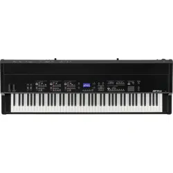
Thank you for purchasing this Kawai MP7SE stage piano.
This owner’s manual contains important information regarding the instrument’s usage and operation.
Please read all chapters carefully, keeping this manual handy for future reference.
About this Owner’s Manual
Before attempting to play this instrument, please read the Introduction chapter from page 10 of this owner’s manual. This chapter
provides a brief explanation of each section of the MP7SE’s control panel, an overview of its various jacks and connectors, and details
how the components of the instrument’s sound are structured.
The Main Operation chapter (page 20) provides an overview of the instrument’s most commonly used functions, beginning with
turning zones on and o, adjusting their volume, and selecting sounds. Later on, this chapter introduces basic sound adjustment
using the four control knobs, before examining how reverb, EFX, and amp simulation can all be applied to dramatically change
the character of the selected sound. Next, the MP7SE’s authentic Tonewheel Organ mode is outlined, explaining how to adjust
drawbar positions using zone faders and control knobs, and change the organ’s percussion characteristics. The chapter closes with
an explanation of the instrument’s global EQ and transpose functions.
The EDIT Menu chapter (page 38) lists all available INT mode and EXT mode parameters by category for convenient reference. The
STORE Button & SETUP Menus chapter (page 64) outlines storing customised sounds, capturing the entire panel conguration as
a SETUP, then recalling dierent SETUPs from the MP7SE’s internal memory.
The Recorder chapter (page 68) provides instructions on how to record and play back pieces stored both in the instrument’s
internal memory, and also MP3/WAV audio les saved to USB memory devices. This chapter also explains the MP7SE’s metronome/
drum pattern functions. Additional USB functions are covered in greater detail in the USB Menu chapter (page 99), while the
SYSTEM Menu chapter (page 105) explains the MP7SE’s system settings and various reset functions.
Finally, the Appendix section (page 119) includes USB-MIDI driver information, software update instructions and listings of the
instrument’s internal sounds, drum rhythms, eects, MIDI reference information, and full specication details.
4
WARNING
Indicates a potential hazard that could result in death or
serious injury if the product is handled incorrectly.
Do not insert or disconnect the power
cord plug with wet hands.
Doing so may cause electric shock.
GROUNDING INSTRUCTIONS
This product must be grounded. If it should malfunction or breakdown, grounding provides a path of least
resistance for electric current to reduce the risk of electric shock. This product is equipped with a cord having
an equipment-grounding conductor and a grounding plug. The plug must be plugged into an appropriate
outlet that is properly installed and grounded in accordance with all local codes and ordinances.
DANGER - Improper connection of the equipment-grounding conductor can result in a risk of electric shock.
Check with a qualied electrician or serviceman if you are in doubt as to whether the product is properly
grounded. Do not modify the plug provided with the product - if it will not t the outlet, have a proper outlet
installed by a qualied electrician.
When using electrical products, the following basic precautions should always be followed:
The product should be connected to
an AC outlet of the specied voltage.
● If you are going to use an AC power cord,
make sure that its has the correct plug shape
and conforms to the specied power voltage.
● Failure to do so may result in re.
120V 240V230V
The product is not completely disconnected from the
power supply even when the power switch is turned
o. If the product will not be used for a long time,
unplug the AC power cord from the AC outlet.
● Failure to do so may cause re in case of
lightning.
● Failure to do so may over-heat the product,
resulting in re.
When disconnecting the AC power cord's
plug, always hold the plug
and pull it to remove it.
● Pulling the AC power cord itself may damage
the cord, causing a re, electric shock or
short-circuit.
When using the headphones, do not
listen for long periods of
time at high volume levels.
Doing so may result in hearing problems.
It is good practice to place the instrument near the AC outlet and the power cord plug in a position so that it
can readily be disconnected in an emergency because electricity is always charging while the plug is in the
AC outlet even in a power switch o condition.
Do not disassemble, repair or modify
the product.
Doing so may result in product breakdown,
electric shock or short-circuit.
Ensure that this product is connected to a socket with a protective earth connection.
Entry of water, needles or hair pins may result
in breakdown or short-circuit.
The product shall not be exposed to dripping or
splashing. No objects lled with liquids, such as
vases, shall be placed on the product.
Take care not to allow any foreign
matter to enter the product.
Important Safety Instructions
Important Safety Instructions
denotes that care should be taken.
The example instructs the user to take care not to allow ngers to be trapped.
denotes a prohibited operation.
The example instructs that disassembly of the product is prohibited.
denotes an operation that should be carried out.
The example instructs the user to remove the power cord plug from the AC outlet.
Examples of Picture Symbols
Read all the instructions before using the product.
CAUTION
RISK OF ELECTRIC SHOCK
DO NOT OPEN
AVIS : RISQUE DE CHOC ELECTRIQUE
- NE PAS OUVRIR.
TO REDUCE THE RISK OF ELECTRIC SHOCK, DO NOT REMOVE COVER (OR BACK).
NO USER-SERVICEABLE PARTS INSIDE. REFER SERVICING TO QUALIFIED SERVICE PERSONNEL.
The lighting ash with arrowhead symbol, within
an equilateral triangle, is intended to alert the user
to the presence of uninsulated "dangerous
voltage" within the product's enclosure that may
be of sucient magnitude to constitute a risk of
electric shock to persons.
The exclamation point within an equilateral
triangle is intended to alert the user to the
presence of important operating and maintenance
(servicing) instructions in the literature
accompanying the product.
WARNING
TO REDUCE THE RISK OF FIRE
OR ELECTRIC SHOCK, DO NOT
EXPOSE THIS PRODUCT TO
RAIN OR MOISTURE.
INSTRUCTIONS PERTAINING TO A RISK OF FIRE, ELECTRIC SHOCK, OR INJURY TO PERSONS
SAVE THESE INSTRUCTIONS
1) Read these instructions.
2) Keep these instructions.
3) Heed all warnings.
4) Follow all instructions.
5) Do not use this apparatus near water.
6) Clean only with dry cloth.
7) Do not block any ventilation openings. Install in
accordance with the manufacturer's instructions.
8) Do not install near any heat sources such as radiators,
heat registers, stoves, or other apparatus (including
ampliers) that produce heat.
9) Do not defeat the safety purpose of the polarized or
grounding-type plug. A polarized plug has two
blades with one wider than the other. A grounding
type plug has two blades and a third grounding
prong. The wide blade or the third prongs are
provided for your safety. If the provided plug does
not t into your outlet, consult an electrician for
replacement of the obsolete outlet.
1 0) Protect the power cord from being walked on or
pinched particularly at plugs, convenience
receptacles, and the point where they exit from the
apparatus.
11) Only use attachments/accessories specied by the
manufacturer.
1 2) Use only with the cart, stand, tripod, bracket, or table
specied by the manufacturer, or
sold with the apparatus. When a cart is used,
use caution when moving the cart/apparatus
combination to avoid injury from tip-over.
1 3) Unplug this apparatus during lightning storms or
when unused for long periods of time.
1 4) Refer all servicing to qualied service personnel.
Servicing is required when the apparatus has been
damaged in any way, such as power-supply cord or
plug is damaged, liquid has been spilled or objects
have fallen into the apparatus, the apparatus has
been exposed to rain or moisture, does not operate
normally, or has been dropped.
5
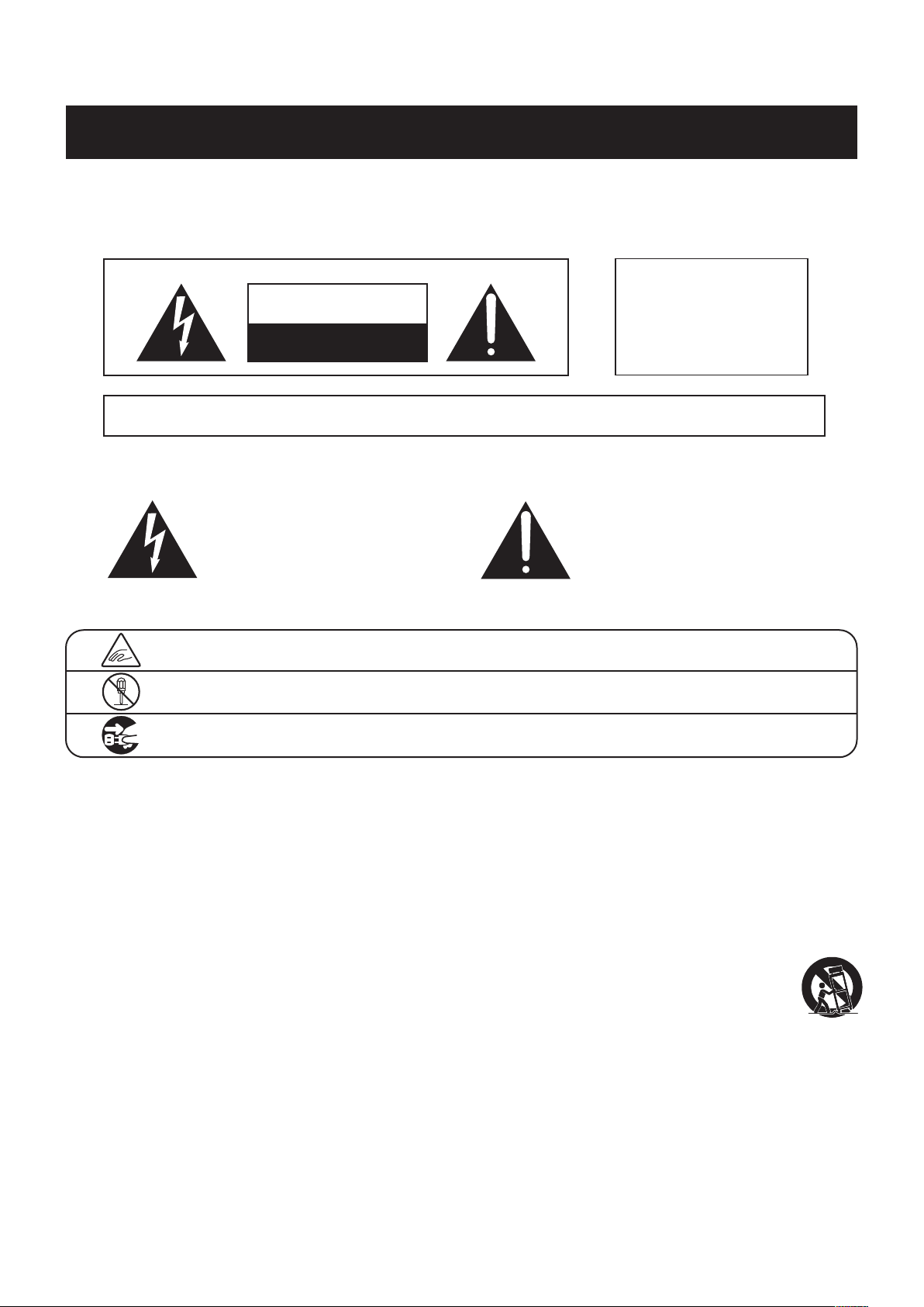
WARNING
Indicates a potential hazard that could result in death or
serious injury if the product is handled incorrectly.
Do not insert or disconnect the power
cord plug with wet hands.
Doing so may cause electric shock.
GROUNDING INSTRUCTIONS
This product must be grounded. If it should malfunction or breakdown, grounding provides a path of least
resistance for electric current to reduce the risk of electric shock. This product is equipped with a cord having
an equipment-grounding conductor and a grounding plug. The plug must be plugged into an appropriate
outlet that is properly installed and grounded in accordance with all local codes and ordinances.
DANGER - Improper connection of the equipment-grounding conductor can result in a risk of electric shock.
Check with a qualied electrician or serviceman if you are in doubt as to whether the product is properly
grounded. Do not modify the plug provided with the product - if it will not t the outlet, have a proper outlet
installed by a qualied electrician.
When using electrical products, the following basic precautions should always be followed:
The product should be connected to
an AC outlet of the specied voltage.
● If you are going to use an AC power cord,
make sure that its has the correct plug shape
and conforms to the specied power voltage.
● Failure to do so may result in re.
120V 240V230V
The product is not completely disconnected from the
power supply even when the power switch is turned
o. If the product will not be used for a long time,
unplug the AC power cord from the AC outlet.
● Failure to do so may cause re in case of
lightning.
● Failure to do so may over-heat the product,
resulting in re.
When disconnecting the AC power cord's
plug, always hold the plug
and pull it to remove it.
● Pulling the AC power cord itself may damage
the cord, causing a re, electric shock or
short-circuit.
When using the headphones, do not
listen for long periods of
time at high volume levels.
Doing so may result in hearing problems.
It is good practice to place the instrument near the AC outlet and the power cord plug in a position so that it
can readily be disconnected in an emergency because electricity is always charging while the plug is in the
AC outlet even in a power switch o condition.
Do not disassemble, repair or modify
the product.
Doing so may result in product breakdown,
electric shock or short-circuit.
Ensure that this product is connected to a socket with a protective earth connection.
Entry of water, needles or hair pins may result
in breakdown or short-circuit.
The product shall not be exposed to dripping or
splashing. No objects lled with liquids, such as
vases, shall be placed on the product.
Take care not to allow any foreign
matter to enter the product.
Important Safety Instructions
denotes that care should be taken.
The example instructs the user to take care not to allow ngers to be trapped.
denotes a prohibited operation.
The example instructs that disassembly of the product is prohibited.
denotes an operation that should be carried out.
The example instructs the user to remove the power cord plug from the AC outlet.
Examples of Picture Symbols
Read all the instructions before using the product.
CAUTION
RISK OF ELECTRIC SHOCK
DO NOT OPEN
AVIS : RISQUE DE CHOC ELECTRIQUE
- NE PAS OUVRIR.
TO REDUCE THE RISK OF ELECTRIC SHOCK, DO NOT REMOVE COVER (OR BACK).
NO USER-SERVICEABLE PARTS INSIDE. REFER SERVICING TO QUALIFIED SERVICE PERSONNEL.
The lighting ash with arrowhead symbol, within
an equilateral triangle, is intended to alert the user
to the presence of uninsulated "dangerous
voltage" within the product's enclosure that may
be of sucient magnitude to constitute a risk of
electric shock to persons.
The exclamation point within an equilateral
triangle is intended to alert the user to the
presence of important operating and maintenance
(servicing) instructions in the literature
accompanying the product.
WARNING
TO REDUCE THE RISK OF FIRE
OR ELECTRIC SHOCK, DO NOT
EXPOSE THIS PRODUCT TO
RAIN OR MOISTURE.
INSTRUCTIONS PERTAINING TO A RISK OF FIRE, ELECTRIC SHOCK, OR INJURY TO PERSONS
SAVE THESE INSTRUCTIONS
1) Read these instructions.
2) Keep these instructions.
3) Heed all warnings.
4) Follow all instructions.
5) Do not use this apparatus near water.
6) Clean only with dry cloth.
7) Do not block any ventilation openings. Install in
accordance with the manufacturer's instructions.
8) Do not install near any heat sources such as radiators,
heat registers, stoves, or other apparatus (including
ampliers) that produce heat.
9) Do not defeat the safety purpose of the polarized or
grounding-type plug. A polarized plug has two
blades with one wider than the other. A grounding
type plug has two blades and a third grounding
prong. The wide blade or the third prongs are
provided for your safety. If the provided plug does
not t into your outlet, consult an electrician for
replacement of the obsolete outlet.
1 0) Protect the power cord from being walked on or
pinched particularly at plugs, convenience
receptacles, and the point where they exit from the
apparatus.
11) Only use attachments/accessories specied by the
manufacturer.
1 2) Use only with the cart, stand, tripod, bracket, or table
specied by the manufacturer, or
sold with the apparatus. When a cart is used,
use caution when moving the cart/apparatus
combination to avoid injury from tip-over.
1 3) Unplug this apparatus during lightning storms or
when unused for long periods of time.
1 4) Refer all servicing to qualied service personnel.
Servicing is required when the apparatus has been
damaged in any way, such as power-supply cord or
plug is damaged, liquid has been spilled or objects
have fallen into the apparatus, the apparatus has
been exposed to rain or moisture, does not operate
normally, or has been dropped.
6
● Doing so may cause the product to become
deformed or fall over, resulting in breakdown
or injury.
Do not stand on the product or exert
excessive force.
● Doing so may result in discoloration or
deformation of the product.
● When cleaning the product, put a soft cloth in
lukewarm water, squeeze it well, then wipe the
product.
Do not wipe the product with benzene
or thinner.
Failure to do so may damage them, resulting in
re, electric shock or short-circuit.
When connecting the AC power cord
and other cords, take care
not to get them tangled.
● Doing so may cause the product to generate
noise.
● If the product generates noise, move the
product suciently away from the electrical
appliance or connect it to another AC outlet.
Do not place the product near electrical
appliances such as TVs and radios.
Please lift up the product when moving it.
Please note that the product is heavy and must
be carried by more than two persons.
Dropping the product may result in breakdown.
Do not drag the product on the oor.
Take care not to drop the product.
Doing so may cause the illumination to fall over,
resulting in re.
Do not place naked ame, such as lighted
candles on the product.
CAUTION
Indicates a potential hazard that could result in injury or
damage to the product or other property if the product
is handled incorrectly.
Using the product in such areas may result in
product breakdown.
Use the product only in moderate climates (not
in tropical climates).
Do not use the product in the following areas.
● Areas, such as those near windows, where the product is
exposed to direct sunlight
● Extremely hot areas, such as near a heater
● Extremely cold areas, such as outside
● Extremely humid areas
● Areas where a large amount of sand or dust is present
● Areas where the product is exposed to excessive
vibrations
Failure to do so may cause breakdown of this
product and other devices.
Before connecting cords, make sure
that the power to this product
and other devices is turned
OFF.
OFF
The product should be located so that its location or position does not interfere with its proper ventilation. Ensure a
minimum distance of 5cm around the product for sucient ventilation.
Failure to do so may over-heat the product,
resulting in re.
Ensure that the ventilation is not
impeded by covering the ventilation
openings with items, such as newspaper,
table-cloths, curtains, etc.
7
The product should be serviced by qualied service personnel when:
• The power supply cord or the plug has been damaged.
• Objects have fallen, or liquid has been spilled into the product.
• The product has been exposed to rain.
• The product does not appear to operate normally or exhibits a marked change in performance.
• The product has been dropped, or the enclosure damaged.
Notes on Repair
Should an abnormality occur in the product, immediately turn the power OFF, disconnect the power cord plug, and then contact
the shop from which the product was purchased.
Instruction for AC power cord (U.K.)
WARNING: THIS APPARATUS MUST BE EARTHED
IMPORTANT: The wires in this mains lead are coloured in accordance with the following code:
• GREEN-AND-YELLOW: EARTH
• BLUE: NEUTRAL
• BROWN: LIVE
As the colours of the wires in the mains lead of this apparatus may not correspond with the coloured markings identifying the
terminals in your plug, proceed as follows.
• The wire which is coloured GREEN-AND-YELLOW must be connected to the terminal in the plug which is marked by the
letter E or by the safety earth symbol or coloured GREEN or GREEN-AND-YELLOW.
• The wire which is coloured BLUE must be connected to the terminal which is marked with the letter N or coloured BLACK.
• The wire which is coloured BROWN must be connected to the terminal which is marked with the letter L or coloured RED.
An information on Disposal for users
If your product is marked with this recycling symbol it means that, at the end of its life, you must dispose of it separately
by taking it to an appropriate collection point. You should not mix it with general household waste. Disposing of this
product correctly will prevent potential negative eects on the environment and human health which could otherwise
arise due to inappropriate waste handling. For further details, please contact your local authority. (European Union only)
FCC Information (U.S.A)
CAUTION: Changes or modications not expressly approved by the party responsible for compliance could void the user’s
authority to operate the equipment.
NOTE: This equipment has been tested and found to comply with the limits for a Class B digital device, pursuant to Part 15 of the
FCC Rules. These limits are designed to provide reasonable protection against harmful interference in a residential installation.
This equipment generates, uses and can radiate radio frequency energy and, if not installed and used in accordance with the
instructions, may cause harmful interference to radio communications. However, there is no guarantee that interference will not
occur in a particular installation. If this equipment does cause harmful interference to radio or television reception, which can be
determined by turning the equipment o and on, the user is encouraged to try to correct the interference by one or more of the
following measures:
• Reorient or relocate the receiving antenna.
• Increase the separation between the equipment and receiver.
• Connect the equipment into an outlet on a circuit dierent from that to which the receiver is connected.
• Consult the dealer or an experienced radio/TV technician for help.
This applies only to products distributed by Kawai America Corporation.
Declaration of Conformity
Products:
Model Number:
Responsible Party Name:
Address:
Telephone:
Electronic Piano
MP7SE
Kawai America Corporation
2055 East University Drive, Rancho Dominguez, CA 90220
310-631-1771
This device complies with Part 15 of the FCC Rules. Operation is subject to the following two conditions:
(1) this device may not cause harmful interference, and
(2) this device must accept any interference received, including interference
that may cause undesired operation.

8
Table of Contents
Important Safety Instructions ...................4
Table of Contents ................................8
Introduction
Welcome to the MP7SE .........................10
1. Feature Highlights ..............................10
2. Owner’s Manual Conventions ..................11
Part Names & Functions ........................12
1. Front Panel: Knobs, Faders & Buttons ...........12
2. Front Panel: Jacks & Connectors ................16
3. Rear Panel: Jacks & Connectors .................16
Connecting to Other Devices ..................18
Understanding the MP7SE .....................19
Main Operation
Getting Started .................................20
Selecting Sounds ...............................21
Zone Functions .................................22
1. Zone Basics .....................................22
2. Zone Modes
(int/ext/both) .........................23
3. Zone Key Range ................................24
LCD Display & Control Knobs ...................26
Eects Section ..................................27
1. Reverb ..........................................27
2. EFX .............................................28
3. Amp Simulator
(MAIN zone only) ....................30
Tonewheel Organ Mode ........................32
Global Section ..................................34
1. EQ. . . . . . . . . . . . . . . . . . . . . . . . . . . . . . . . . . . . . . . . . . . . . . . 34
2. Transpose .......................................36
3. Local O ........................................37
EDIT Menu
Overview of the EDIT Menu (INT mode) ............38
EDIT Menu parameters (INT mode) ................40
1. Reverb ..........................................40
2.1. EFX ............................................40
2.2. Amp Simulator
(MAIN zone) ......................41
3. Sound ..........................................42
4. Tuning ..........................................45
5. Key Setup .......................................46
6. Controllers ......................................49
7. Knob Assign ....................................51
8. Virtual Technician
(PIANO sounds) ..................52
Virtual Technician
(E.PIANO, HARPSICHORD, BASS sounds) ...53
Virtual Technician
(DRAWBAR sounds) .................53
Overview of the EDIT Menu (EXT mode) ...........54
EDIT Menu parameters (EXT mode) ................56
1. Channel/Program ...............................56
2. SETUP ..........................................56
3. Transmit
....................................57
4. MMC
.......................................57
5. Key Setup .......................................58
6. Controllers ......................................60
7. Knob Assign ....................................62
Overview of the EDIT Menu (BOTH mode) ..........63
STORE Button & SETUPs
Overview of the STORE Button .................64
1. Storing a SOUND ...............................64
2. Storing a SETUP ................................. 65
3. Storing POWERON settings .....................66
SETUP Memories ...............................67

9
Table of Contents
Recorder
Overview of the Recorder ......................68
Song Recorder (Internal memory) ....................69
1. Recording a song ...............................69
2. Playing back a song. . . . . . . . . . . . . . . . . . . . . . . . . . . . . 71
3. Saving a song as an SMF le ....................73
4. Loading an SMF le into memory ..............74
5. Erasing a song ..................................77
6. Song Transpose .................................78
7. Panel Mode .....................................78
8. MIDI to Audio ...................................78
9. SMF Direct Play .................................79
SMF Mixer .......................................80
Audio Record/Playback (USB memory) ..............81
1. Recording an audio le .........................81
2. Playing an audio le ............................84
3. Overdubbing an audio le ......................87
4. MIDI to Audio ...................................90
Metronome .....................................93
1. Click mode ......................................93
2. Rhythm mode ..................................94
3. Recording with the metronome ................97
USB Menu
Overview of the USB Menu .....................99
USB Menu Functions ..........................100
1. Load ...........................................100
2. Save ...........................................101
3. Delete .........................................102
4. Rename ........................................103
SYSTEM Menu
Overview of the SYSTEM Menu ...............105
SYSTEM Menu Parameters & Functions .......106
1. Utility ..........................................106
2. Pedal/Mod. ....................................108
Expression pedal calibration ...................109
3. MIDI ...........................................110
4. Oset ..........................................111
5. User Edit .......................................111
Creating a User Touch Curve ...................112
Creating a User Temperament .................113
Creating a User Key Volume ...................114
Creating a User Stretch Tuning ................. 115
Creating a User Voicing ........................116
6. Reset ........................................... 117
Panic button ...................................117
Panel Lock ( ) .................................118
Appendix
Troubleshooting ...............................119
USB MIDI (USB to Host connector) .....................124
Software Update ..............................125
Sound List .....................................126
Rhythm Pattern List ...........................127
EFX Categories, Types, & Parameters .........128
Specications ..................................133
MIDI Implementation .........................134
1. Recognised Data ...............................135
2. Transmitted Data ..............................139
3. Exclusive Data .................................141
4. SOUND/SETUP Program/Bank .................153
5. Program Change Number List .................154
6. Control Change Number (CC#) Table ..........157
MIDI Implementation Chart ......................158

10
Introduction
1
Feature Highlights
‘Responsive Hammer III’ weighted-key action, with Ivory Touch key surfaces and Let-o simulation
The MP7SE’s Responsive Hammer III (RH III) keyboard action recreates the distinctive touch of an acoustic grand piano, with
its realistic movement and accurate 3-sensor technology providing a smooth, natural, and highly responsive piano playing
experience. The weight of the keyboard is appropriately graded to mirror the heavier bass hammers and lighter treble hammers
of an acoustic piano, while structural reinforcements within the action assembly ensure greater stability during fortissimo and
staccato passages.
The RH III keyboard action also reproduces the subtle let-o sensation felt when playing the keys of a grand piano very softly,
enhancing delicate pianissimo playing to satisfy the expectations of even the most discerning pianists. Finally, the MP7SE
keyboard action features Kawai’s Ivory Touch key surfaces as standard. This nely textured material gently absorbs moisture to
assist playing control, and possesses a natural, matte nish that is smooth, but not slippery.
The ultimate pianos for Concert, Pop, and Jazz
The MP7SE captures the beautiful sound of Kawai’s SK-EX, EX, and SK-5 acoustic grand pianos, with all 88 keys of these exceptional
instruments meticulously recorded, analysed and faithfully reproduced using proprietary Harmonic Imaging™ technology. This
unique process accurately recreates the broad dynamic range of the original grand pianos, aording pianists an extraordinary
level of expressiveness ranging from the softest pianissimo to the strongest, boldest fortissimo.
With separate categories for Concert, Pop, and Jazz playing, the MP7SE oers an excellent selection of high quality acoustic piano
sounds suitable for various musical styles, including separate sub-categories for upright and mono pianos.
Moreover, Kawai’s unique Virtual Technician feature allows various characteristics of the selected acoustic piano sound to be
shaped at the touch of a button or the turn of a knob, with parameters to adjust voicing and regulation, string and damper
resonances, and subtle hammer, damper, and key release noises.
Vintage EPs, twin eects, and amp simulation
The MP7SE also features an excellent selection of vintage electric piano sounds, each with their own distinctive characteristics.
Enjoy their natural, organic sound, or pass the signal through a wide variety of classic eects stomp boxes, before plugging into
one of the ve classic amp and speaker cabinets – complete with realistic microphone character and position modelling.
Classic tonewheel organs with drawbar control and authentic percussion
The MP7SE’s brand new tonewheel organ simulation transforms the stage piano into a vintage electromechanical organ, complete
with nine real-time adjustable drawbars and authentic percussion controls. Organ enthusiasts can dial-in favourite drawbar
registrations, adjust the ‘condition’ of the organ tone, and select their preferred rotary speaker character, then store the sound to
memory for immediate recall. With organ mode selected, the MP7SE adjusts the strike point for the keyboard, allowing blazing
runs and greasy licks to be played on its fully-weighted action as easily as the real thing.
High quality strings, pads, brasses, basses and more
Supplementing the realistic acoustic pianos, vintage electric pianos, and growling tonewheel organs, the MP7SE features a broad
range of high quality strings, pads, synths, brass and woodwind voices, basses, guitars, and a whole host of other useful sounds.
These supplementary sounds are ideal for building layers, adding texture to other instruments, or for playing individually, at
the front of the mix. And if the stock sound isn’t quite perfect, feel free to customise and tweak using the MP7SE’s exible ADSR
parameters and resonance/cut-o controls – all immediately accessible directly from the panel.
Four zone master keyboard controller
The MP7SE maintains the MP series’ classic four-zone approach, with each zone able to play internal sounds, external MIDI devices,
or both types simultaneously. Zones can be played individually, or freely split, layered and velocity switched to create stunning
personalised performances. The MP7SE’s powerful customisation allows parameters and settings for each zone to be adjusted
and controlled independently, making for an unbelievably versatile all-in-one performance instrument.
Intuitive operation, large LCD, real-time assignable control knobs
The MP7SE’s control panel is clearly arranged and easy to use, with related functions grouped together and placed where you’d
expect to nd them. A large LCD display and four assignable control knobs, allow several parameters to be adjusted directly in
real-time, without getting lost in menus – concentrate on playing, rather than trying to remember which button does what.
Welcome to the MP7SE
11
Introduction
256 Setup memories: enough for the busiest stage musician
The MP7SE allows every single customised sound, knob position, fader level, and adjustable parameter to be stored in memory as
a SETUP, and recalled at the touch of a button. With over 250 SETUP memories, the MP7SE is ideal for busy stage musicians who
like to plan several shows ahead, before going out on the road.
USB to Device functionality, with MP3/WAV/SMF le recording and playback
The MP7SE is equipped with USB connectors that not only allow the instrument to be connected to a computer for MIDI use,
but also to load and save data to USB memory devices directly. This ‘USB to Device’ feature allows customised sounds, SETUP
memories, and recorder songs stored in internal memory to be saved to USB for posterity.
USB memory devices can also be used to play back MP3 or WAV audio or SMF MIDI les, allowing performing musicians to
play along with professional backing tracks, or simply learn the chords or melody for a new piece. It is even possible to save
performances directly as MP3, WAV, or SMF les for emailing to band members, casual listening away from the keyboard, or further
editing using an audio workstation.
2
Owner’s Manual Conventions
This owner’s manual utilises a number of illustrative conventions in order to explain the MP7SE’s various functions.
The examples below provide an overview of the button LED indicator states and press types, and the appearance of
dierence kinds of explanation text.
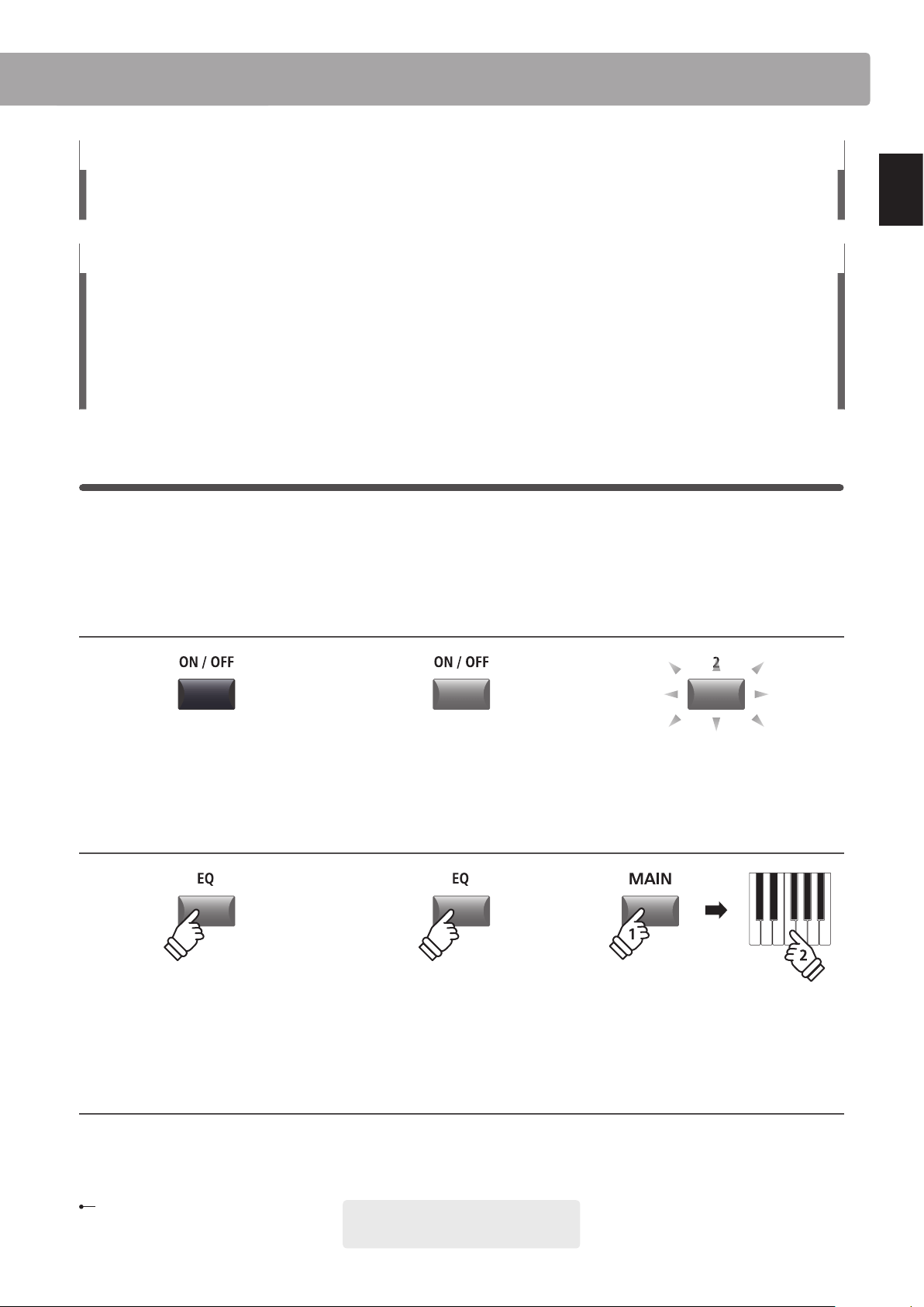
Button LED indicator states
LED indicator OFF:
Sound/Function is not selected.
LED indicator ashing:
Sound/Function is selected in a
temporary state.
LED indicator ON:
Sound/Function is selected.
Button press types
Normal press:
Select a sound or function, or
turn a function ON/OFF.
Press and hold, then press X:
Set split points, create zone
ranges, set transpose key, etc.
Press and hold:
Show a function’s parameters.
hold
hold
Text appearance
Normal instruction and explanation text
is written in regular type at 9 pt. size.
* Notes about functions are marked with an
asterisk and written in 7.5 pt. size.
Reminders, hints, and additional explanations
are written in italic type at 9 pt. size.
Captions explaining the LCD display
or button functions, are written in
bold type at 8.5 pt. size.
Example operations are written in italic type
at 8 pt. size, and enclosed within a grey box.
Welcome to the MP7SE
12
Introduction
1
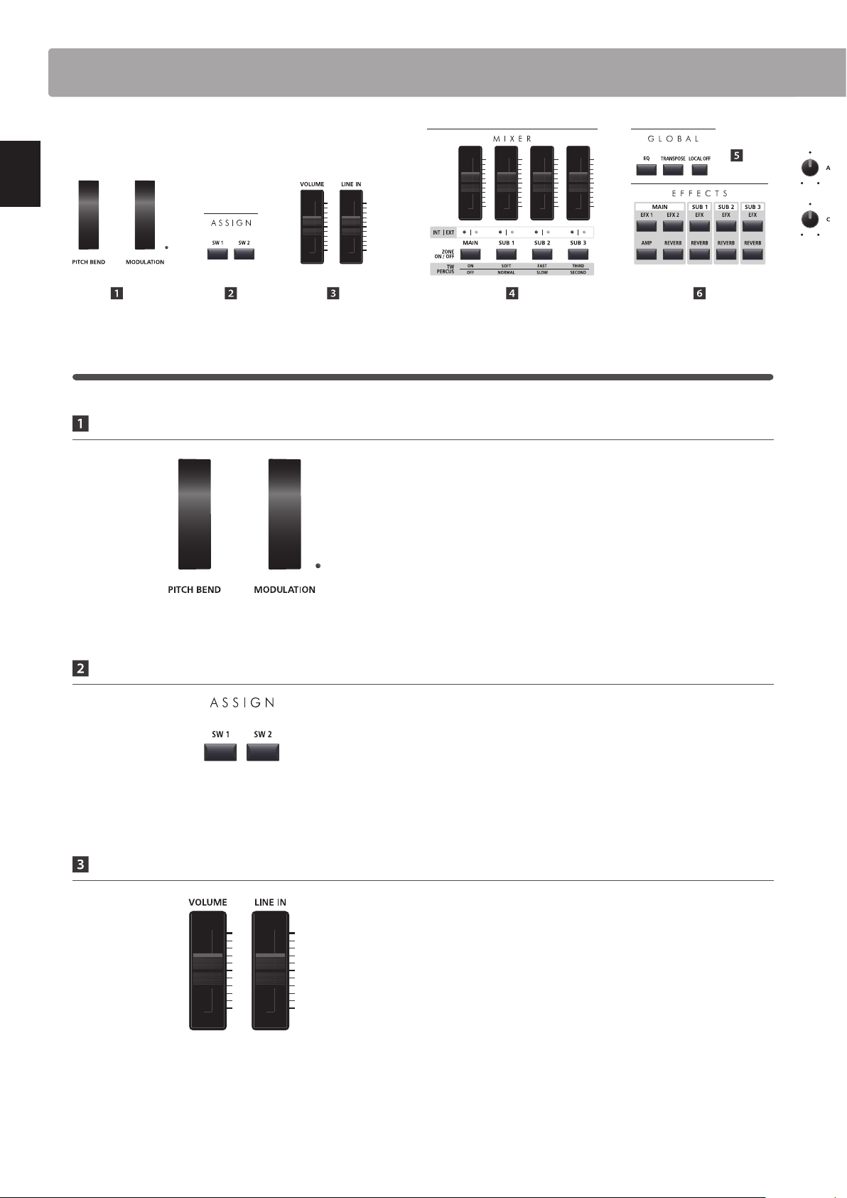
Front Panel: Knobs, Faders & Buttons
Control Wheels
PITCH BEND wheel
This control wheel smoothly bends the pitch up or down from
its current value.
MODULATION wheel
This control wheel controls the modulation (vibrato) depth.
Moving the wheel forward increases the vibrato depth.
The LED indicator will turn ON when this wheel is in use.
* Alternative functions can be assigned to the MODULATION wheel in the
Controllers page of the EDIT menu (page 49).
ASSIGN Buttons
SW1 / SW2 buttons
These buttons turn user-assigned functions ON or OFF.
Various dierent functions can be assigned to these buttons,
allowing immediate control during performances.
* Press and hold either button to show the respective assign parameters of
the EDIT menu in the LCD display.
* For more information about assigning functions, please refer to page 49.
Volume Faders
MASTER VOLUME fader
This fader controls the volume level of the MP7SE’s OUTPUT and
HEADPHONE jacks.
LINE IN fader
This fader controls the LINE IN volume level.
* The LINE IN volume level can be further adjusted by using the Input Level
parameter in the Utility page of the SYSTEM menu. For more information,
please refer to page 107.
Part Names & Functions
13
Introduction
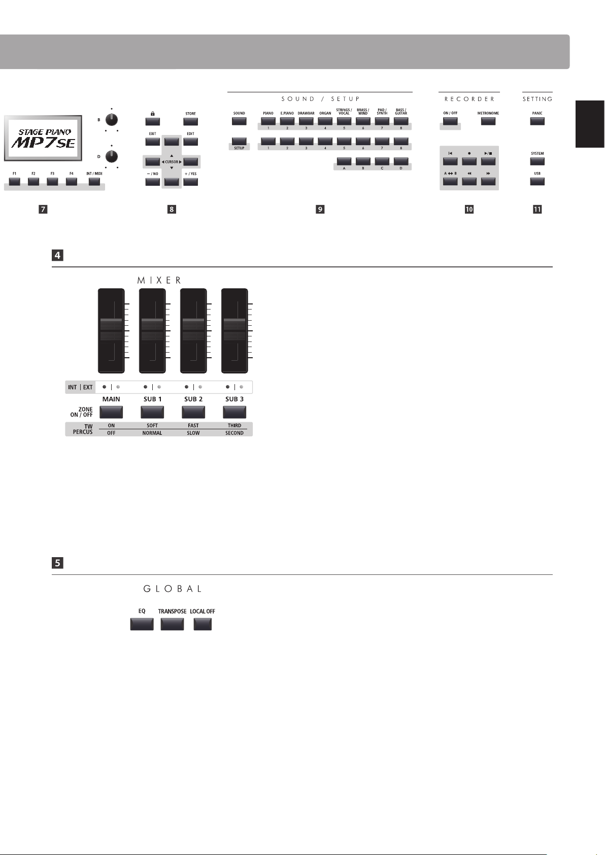
MIXER Section
VOLUME faders
These faders control the individual volume levels of the MAIN,
SUB1, SUB2, and SUB3 zones. When multiple zones are active,
these faders can be used as an audio mixer.
When the tonewheel organ mode is selected, these faders are
used to adjust the position of the assigned drawbars.
INT/EXT LEDs
These LEDs indicate whether a zone is controlling an internal
sound, an external MIDI device, or both simultaneously.
ZONE ON/OFF buttons
These buttons turn the MAIN, SUB1, SUB2, and SUB3 zones ON
or O FF.
When the tonewheel organ mode is selected, these buttons are
used to change the percussion characteristics of the organ.
* When the key range is set, the LED indicator for the zone button will also
turn green.
* Press and hold each zone button to show the respective key range setting
pop-up in the LCD display.
GLOBAL Section
EQ button
This button turns the global EQ ON or OFF.
* Press and hold this button to show the EQ settings in the LCD display.
TRANSPOSE button
This button turns the TRANSPOSE function ON or OFF.
* Press and hold this button to show the transpose settings pop-up in the
LCD display.
LOCAL OFF
This button disables the internal connection between the
MP7SE’s keyboard and tone generators.
Part Names & Functions
14
Introduction
Part Names & Functions
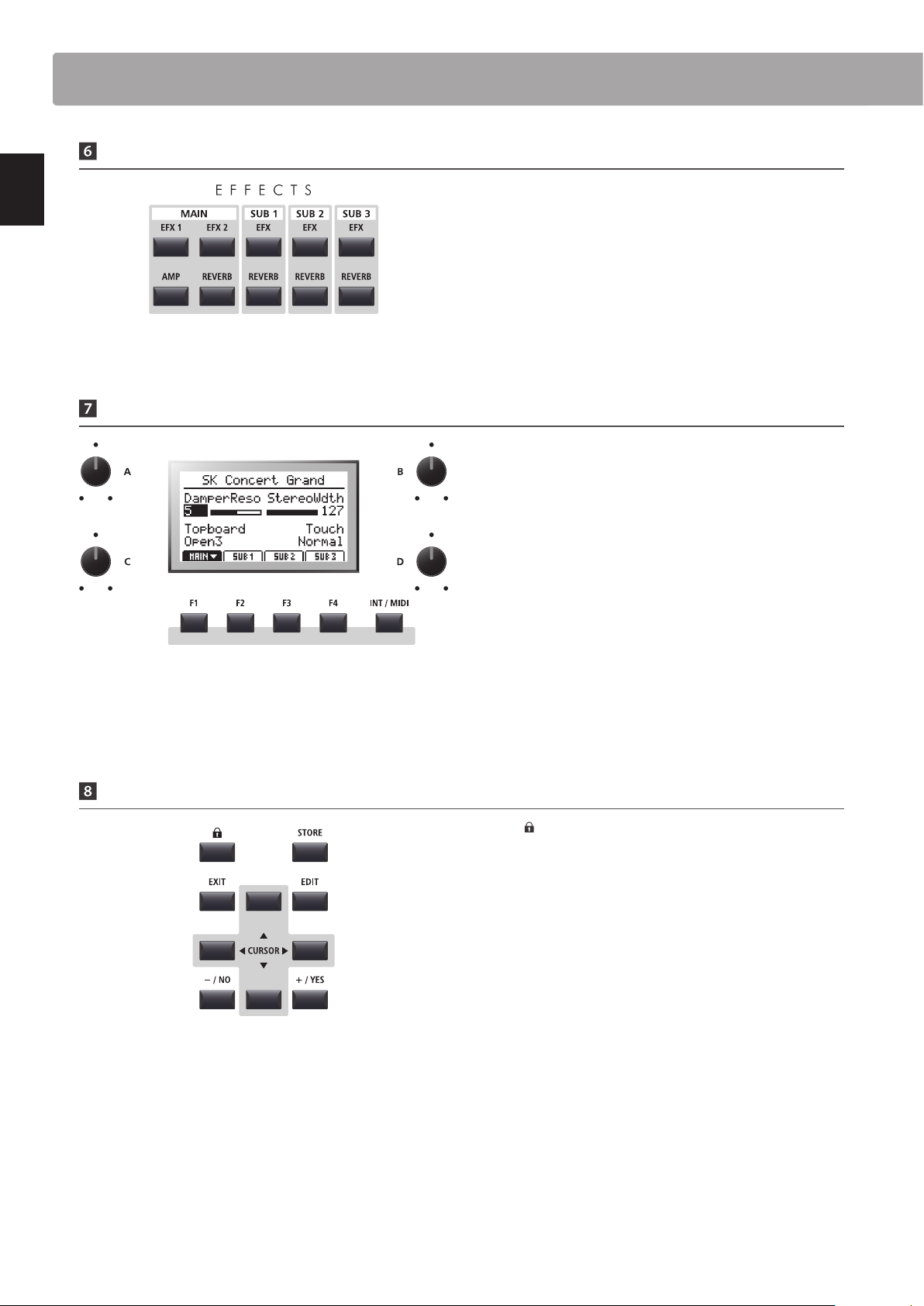
EFFECTS Section
EFX1/EFX2/EFX buttons
These buttons turn the eects for each zone ON or OFF. The
MAIN zone has two eect modules, while the SUB1, SUB2, and
SUB3 zones have one eect module each.
AMP button
This button turns the amp simulator for the MAIN zone ON or
OFF.
REVERB buttons
These buttons turn the reverb for each zone ON or OFF.
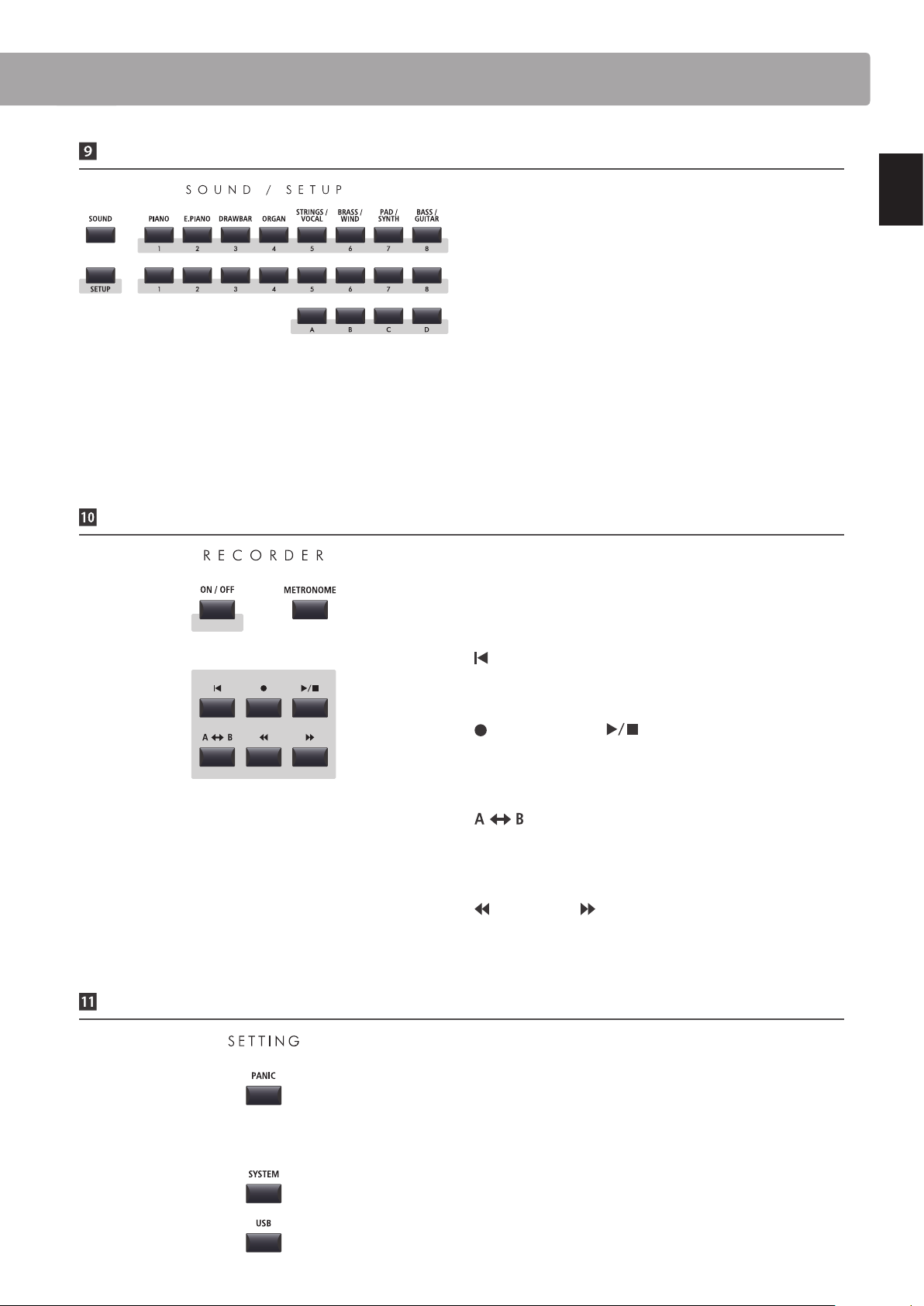
DISPLAY Section
LCD Display
The LCD display provides a visual indication of the selected zone
and sound, parameter values, and the status of other functions
when active.
A/B/C/D control knobs
These knobs adjust displayed parameter values in real-time.
* EDIT menu parameters can be freely assigned to each of the four knobs in
the Knob Assign page of the EDIT menu (page 51).
F1/F2/F3/F4 buttons
These buttons select the four zones (MAIN, SUB1, SUB2, SUB3)
to be displayed and controlled. In other modes (e.g. Recorder)
these buttons also select additional functions.
INT / MIDI button
This button is used in conjunction with the +/YES or –/NO
buttons to change the zone mode (INT, EXT, or BOTH).
EDIT Section
LOCK ( ) button
This button locks the MP7SE’s control panel, thus preventing
any accidental button pushes during a performance.
STORE button
This button stores edited SOUNDS, or full panel settings to the
SETUP and POWERON memories.
EXIT button
This button exits the current mode or page.
EDIT button
This button enters the EDIT menu. When the EDIT menu is
displayed, this button also enters the selected parameter
category page.
CURSOR buttons
These buttons move the selection cursor and scroll through the
various pages of the EDIT menu.
– / NO + / YES buttons
These buttons decrease or increase the value of the selected
parameter, and also cancel or conrm operations that require
user interaction (e.g. Erasing data).
* Press and hold each button to show the respective settings pages of the
EDIT menu in the LCD display.
15
Introduction
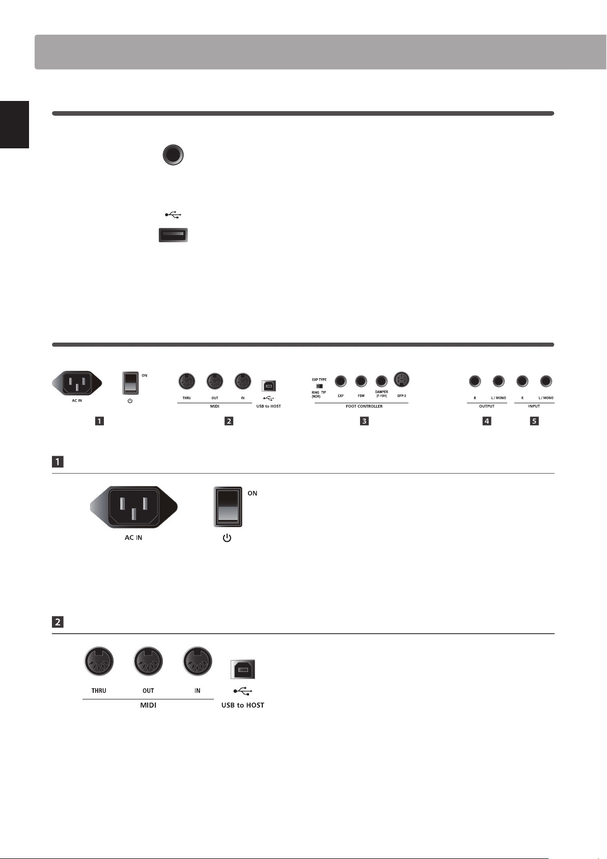
SOUND / SETUP Section
SOUND button
This button sets the MP7SE to SOUND mode, whereby the
buttons on the right will select the instrument’s 256 internal
sounds.
SETUP button
This button sets the MP7SE to SETUP mode, whereby the
buttons on the right will select the instrument’s 256 SETUP
memories.
* Press this button while in SETUP mode to show the SETUP summary pop-
up in the LCD display.
SOUND/SETUP SELECTION buttons
In SOUND mode, these buttons select the category, type, and
variation of the zone’s sound. In SETUP mode, these buttons
select the bank and memory used for the SETUP.
RECORDER Section
ON/OFF button
This button turns the RECORDER section ON or OFF.
METRONOME button
This button activates the METRONOME or RHYTHM patterns.
(RESET) button
This button resets the MP7SE’s song recorder, rewinding songs
and MP3/WAV/SMF les to the beginning.
(RECORD) and (PLAY/STOP) buttons
These buttons record and playback/stop songs stored in the
MP7SE’s internal memory, or MP3/WAV les saved to a USB
memory device.
(LOOP) button
This button activates the MP7SE’s A-B Loop function, allowing
passages of a recorder song or MP3/WAV/SMF le to be played
back repeatedly.
(REW) and (FWD) buttons
These buttons are used to move the playing position of the
current recorder song or MP3/WAV/SMF backward or forward.
SETTING Section
PANIC button
This button returns the MP7SE to the Power On state, and also
sends All Note O and Reset All Controller messages via MIDI.
SYSTEM button
This button enters the SYSTEM menu, allowing many aspects of
the MP7SE’s functionality to be adjusted.
USB button
This button enters the USB menu, allowing data to be loaded
and saved from/to a connected USB memory device.
Part Names & Functions
16
Introduction
2
Front Panel: Jacks & Connectors
HEADPHONE jack
The headphone jack is located at the left end of the key slip and
used to connect a pair of headphones equipped with a standard
1/4” phone jack.
USB TO DEVICE port
The USB to Device port is located at the right end of the key
block and used to connect a FAT or FAT32 formatted USB
memory device to load and save data.
* Please note that wireless ash memory devices are not compatible with
the MP7SE.
3
Rear Panel: Jacks & Connectors
POWER Section
AC IN
Connect the power cable included with the MP7SE to this
receptacle.
POWER SWITCH
This switch turns the MP7SE ON and OFF.
* The MP7SE features a power saving mode that can turn o the instrument
automatically after a specied period of inactivity. For more information,
please refer to page 107.
MIDI Section
MIDI THRU/OUT/IN jacks
These jacks are used to connect the MP7SE to external MIDI
devices, and also to a computer with a MIDI interface as an
alternative to the ‘USB to Host’ port.
USB TO HOST port
This port is used to connect the MP7SE to a computer using a
USB cable. When connected, the instrument can be used as a
standard MIDI device, allowing it to send a receive MIDI data.
Connect a ‘B’ type USB connector to the instrument, and an ‘A’
type USB connector to the computer.
* When connecting the MP7SE to a computer using the ‘USB to Host’ port,
additional driver software may be required. For more information, please
refer to page 124.
Part Names & Functions
.
* The instrument’s USB MIDI port and MIDI IN/OUT jacks can be connected
and used simultaneously. To adjust MIDI routing, please refer to the MIDI
parameters in the SYSTEM menu, explained on page 110.
17
Introduction
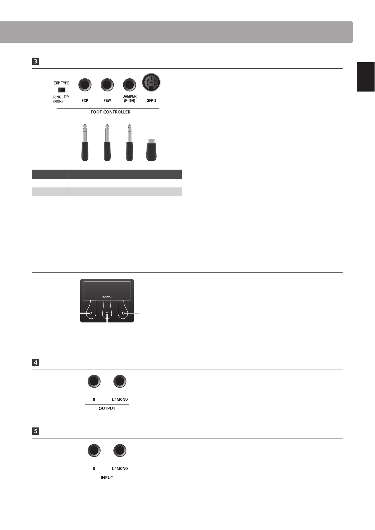
FOOT CONTROLLER Section
EXP TYPE switch
This switch is used to select the EXP pedal’s TRS connector type.
EXP jack
This jack is used to connect an expression pedal to the MP7SE.
* For information about calibrating the expression pedal to ensure correct
operation with the MP7SE, please refer to page 109.
FSW jack
This jack is used to connect a momentary foot switch pedal to
the MP7SE.
* If the foot switch pedal is not turned o when releasing it, check the FSW
polarity. Please refer to page 108.
DAMPER (F-10H) jack
This jack is used to connect the included F-10H damper pedal
to the MP7SE.
GFP-3 jack
This jack is used to connect the optional Kawai GFP-3 triple
pedal accessory to the MP7SE.
Kawai GFP-3 triple pedal accessory: default pedal assignments
By default, with the optional GFP-3 triple pedal unit connected,
the right pedal acts as a damper pedal, the centre pedal acts as
a sostenuto pedal, and the left pedal functions as a soft pedal.
* Functions can be freely assigned to each foot controller in the Controllers
page of the EDIT menu. For more information, please refer to page 49.
OUTPUT Section
OUTPUT jacks
These jacks are used to connect the MP7SE to a musical
instrument amplier, PA system, or recording console using
standard 1/4” phone jacks. To output a mono signal, connect
the cable to the L/MONO jack.
INPUT Section
INPUT jacks
These jacks are used to connect a pair of stereo outputs from
other electronic instruments or audio equipment to the MP7SE.
The input level can be easily adjusted using the LINE IN fader.
When connecting a mono audio source, connect the cable to
the L/MONO jack only.
* When using the Audio Recorder function, the INPUT audio will also be recorded
to the WAV/MP3 le. For more information, please refer to page 81.
Left pedal:
Soft
Centre pedal:
Sostenuto
Right pedal:
Damper
* Functions can be freely assigned to each foot controller in the Controllers
page of the EDIT menu. For more information, please refer to page 49.
* For more information about purchasing the GFP-3 triple pedal accessory,
please contact your local Kawai distributor.
Part Names & Functions
Expression
FSW
F10-H
GFP-3
EXP type Description
RING (NOR) TRS plug’s Ring to WIPER
TIP TRS plug’s Tip to WIPER
18
Introduction
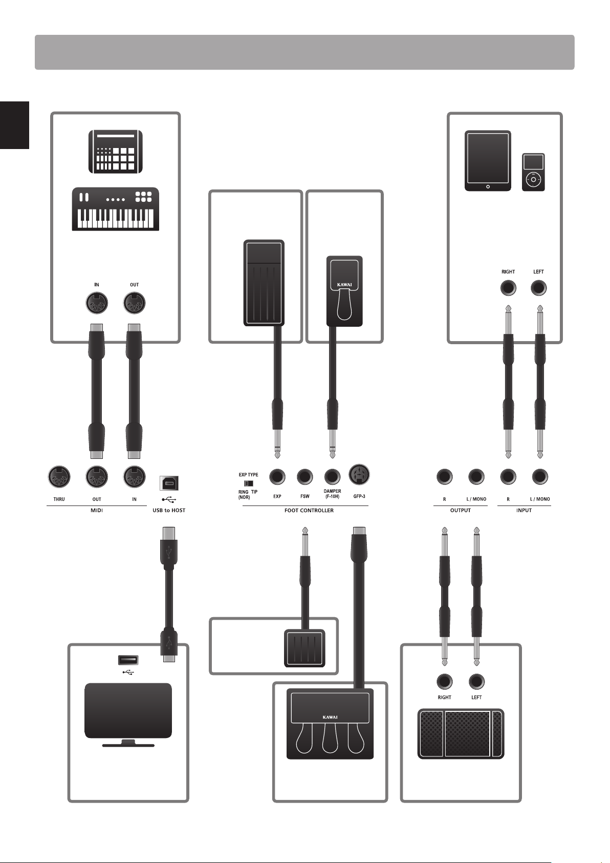
Connecting to Other Devices
Control external MIDI devices,
or connect to a computer with a
MIDI interface.
Connect to a computer to
exchange MIDI data and
use DAW software.
Connect the GFP-3 triple
pedal unit accessory.
USB type ‘B’
USB type ‘A’
Connect an expression
pedal. Set the correct
EXP TYPE.
Connect to ampliers,
speakers, etc.
Connect the stereo output
from tablets, portable
audio devices or other
electronic instruments.
Connect the
included F-10H
damper pedal.
Connect a
footswitch pedal.
19
Introduction
Understanding the MP7SE
Preparation before use
The MP7SE does not feature built-in speakers. Therefore, in order to listen to the MP7SE, it will rst be necessary to connect a mixer,
keyboard amplier, or headphones to the instrument.
Once connected to an audio output device, press the POWER SWITCH located on the right of the rear panel to turn on the MP7SE.
It is recommended to turn on the MP7SE before the audio output device in order to avoid the unpleasant switching noise that can
sometimes occur.
MP7SE zone structure: explanation
The MP7SE features 4 zones: MAIN, SUB1, SUB2, and SUB3. Each zone features a dedicated VOLUME fader and can be turned ON or OFF
freely. Zones can be set to INT (play the MP7SE’s internal sounds), EXT (control external MIDI devices) or INT and EXT simultaneously.
When a zone is set to INT, the process of selecting and assigning sounds is largely identical for each zone. However, there are some
important dierences between the MAIN zone and three SUB zones. First, the MAIN zone features two separate EFX modules and
an additional AMP simulator, while the SUB zones each feature one EFX module only. Moreover, the MAIN zone allows any of the 129
eects to be assigned to both EFX modules, however the variety of eects available to the SUB zones’ EFX modules is limited to 22
eects. Finally, the MP7SE’s tonewheel organ mode can only be used with the MAIN zone is selected, thus the SUB zones are limited
to using the standard PCM organ sounds. All sounds are adjusted using the various parameters in the EDIT menu, with additional
‘Feature Parameters’ that are specic to certain sounds.
REVERB settings are common for all zones, however the depth parameter can be controlled independently for each zone. The
MP7SE’s EQ is also common for all zones, however parameters in the EDIT menu allow the tonal character for each zone’s sound to
be adjusted independently.
When set to EXT, zones are used to control external MIDI devices. The MAIN and SUB zones share the same MIDI capabilities, allowing
up to four MIDI channels to be independently controlled at the same time. As with INT mode, various parameters to dene transmit/
receive channels, MMC features, keyboard ranges, and knob assignments can be accessed for each EXT zone via the EDIT menu.
Modications to each sound can be stored as individual SOUND presets, while the entire conguration of the MP7SE itself can be
stored in one of the 256 SETUP memories.
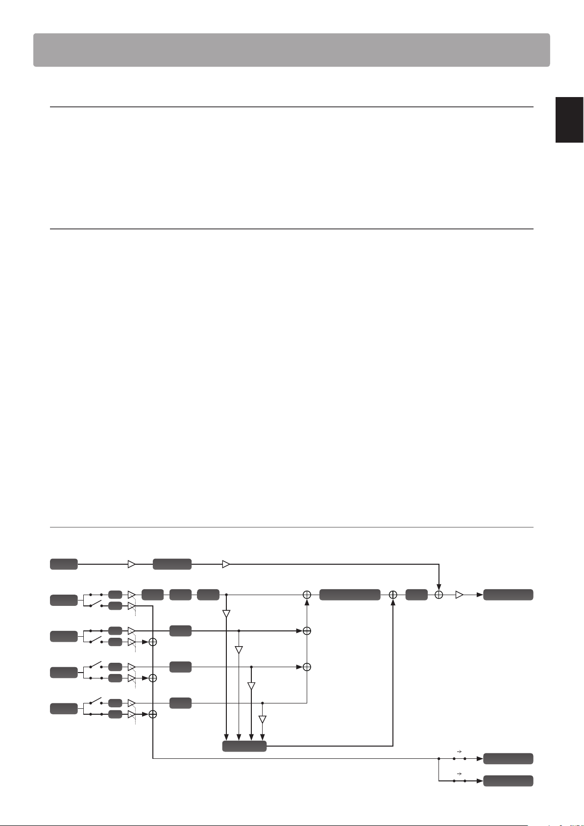
MP7SE zone structure: block diagram
The diagram below illustrates the zone structure of the MP7SE.
MAIN Reverb Depth
SUB1 Reverb Depth
SUB3 Reverb Depth
Reverb
Master Fader
SUB2 Reverb Depth
MAIN
EXT
INT
EFX1Amp EFX2
SUB1
EXT
INT
SUB2
EXT
INT
SUB3
EXT
INT
EFX
EFX
EFX
USB-MIDI Out
MIDI Out
Line In
Virtual Technician
Normal Out
EQ
Noise Gate
Line In Fader Input Level
MAIN Fader
SUB1 Fader
SUB2 Fader
SUB3 Fader
Key MIDI
Key USB
Zone Mode
20
Main Operation
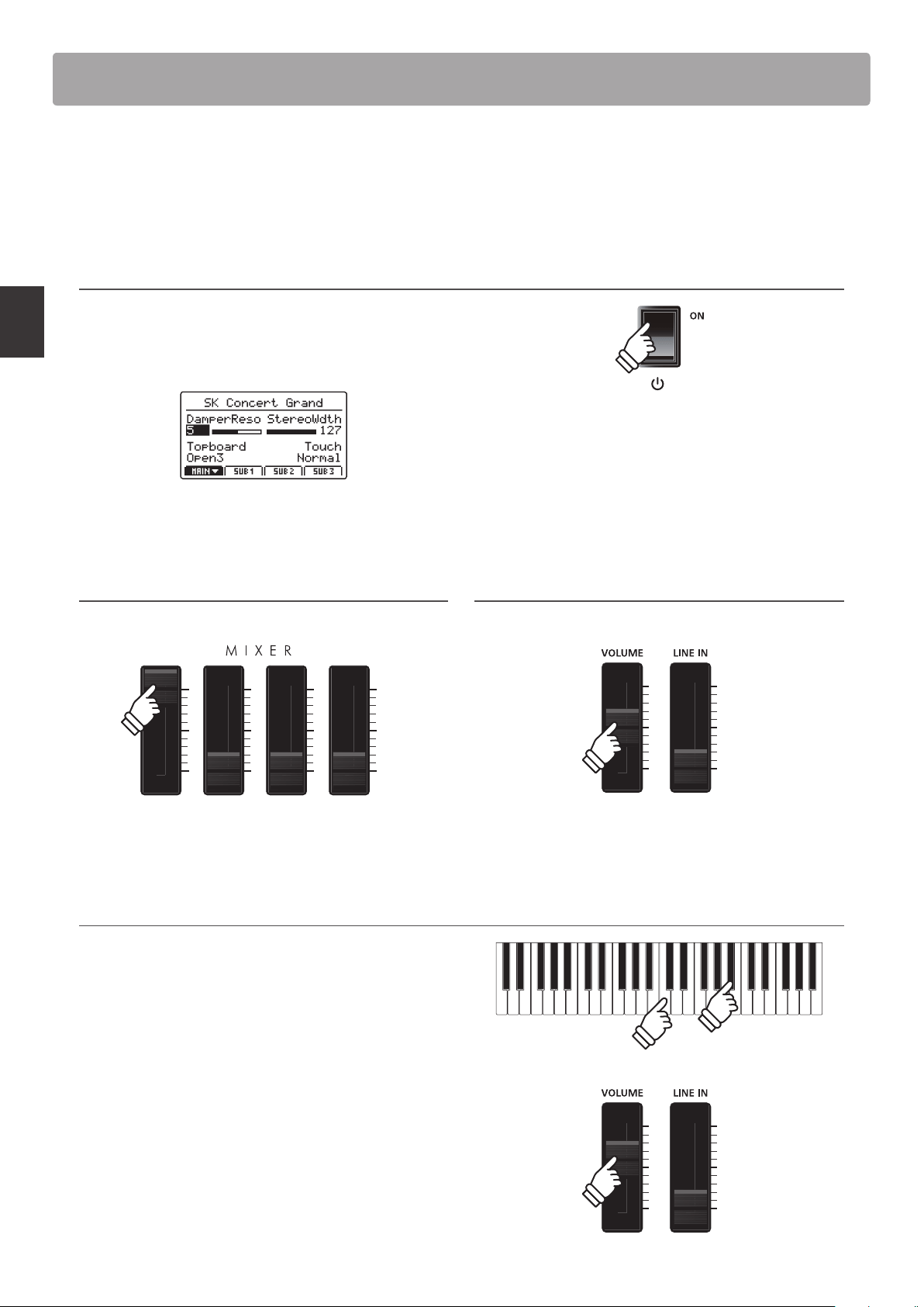
Getting Started
After connecting the power cable, speakers/headphones, and pedals, it’s time to start playing the MP7SE stage
piano. This page will explain how to turn on the instrument, set the MAIN zone volume, and adjust the master
volume.
1. Turning the MP7SE ON
Press the POWER SWITCH.
The instrument will turn ON, and after a brief period the main
Play Mode screen will be shown in the LCD display.
* For more information about the play screen, please refer to page 26.
2. Adjusting the MAIN zone volume
Move the MAIN zone volume fader to the top-most position.
* For more information about adjusting the volume of zones, please refer
to page 22.
3. Adjusting the MP7SE’s master volume
Move the MASTER VOLUME fader to the half-way position.
4. Playing the piano
Start playing the piano.
The rich sound of a Kawai SK-EX Concert Grand Piano will be
heard as the keys are pressed.
If necessary, increase or decrease the MASTER VOLUME fader to
nd a comfortable listening level.
* The MP7SE features a power saving mode that can turn o the instrument
automatically after a specied period of inactivity. For more information,
please refer to page 107.
21
Main Operation
The MP7SE stage piano features a wide selection of realistic instrument sounds suitable for various musical styles
Sounds are arranged into eight categories, with eight further sub-categories, and four variations, providing a total
of 256 dierent instrument sounds. For a complete listing of the available instrument sounds, please refer to page
126 of this owner’s manual.
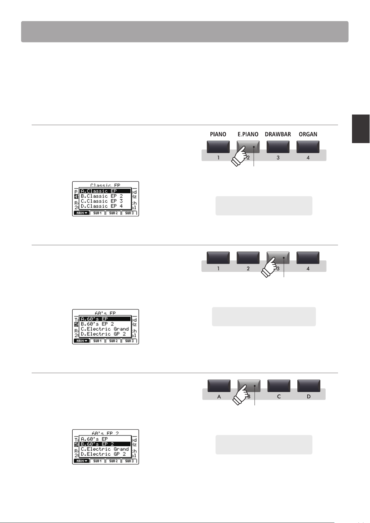
* The example below will explain how to select the ‘60’s EP 2’ electric piano sound, however the process is identical for all other sounds.
1. Selecting the sound category
Press the desired sound category button from the top row of
sound buttons.
The LED indicator for the button will turn ON to indicate that
the category is selected, and a sound variation pop-up list will
briey be shown in the LCD display.
2. Selecting the sound sub-category
Press the desired sound sub-category button from the middle
row of sound buttons.
The LED indicator for the button will turn ON to indicate that the
sub-category is selected, and a sound variation pop-up list will
briey be shown in the LCD display.
3. Selecting the sound variation
Press the desired sound variation button from the bottom row
of sound buttons.
The LED indicator for the button will turn ON to indicate that
the variation is selected, and a sound variation pop-up list will
briey be shown in the LCD display.
* Sounds can be selected by pressing the category, sub-category, and
variation buttons in any order.
* When selecting a dierent sound category, the previously selected sub-
category and variation will be recalled automatically.
Example: To select the Electric Piano sound
category, press the E.PIANO button.
LED indicator ON:
Category is selected
LED indicator ON:
Sub-category is selected
Example: To select the third sub-category of
electric pianos, press the ‘3’ sub-category button.
LED indicator ON:
Sound variation is selected
Example: To select the ‘60’s EP 2’ sound, press
the ‘B’ sound variation button.
Selecting Sounds
22
Main Operation
1
Zone Basics
As noted in the Introduction chapter, the MP7SE features four zones: MAIN, SUB1, SUB2, and SUB3. This page will
explain the process for turning zones ON and OFF, adjusting zone volumes, and creating a simple two zone layer.
Turning a zone ON or OFF
Press the button corresponding to the desired zone to turn that
zone ON or OFF.
The LED indicator for the pressed zone button will turn ON or
OFF to indicate the current status of the zone.
If a zone is turned OFF but then selected, a
symbol will be
added to the left of the sound name in the LCD display.
Zone is
turned OFF
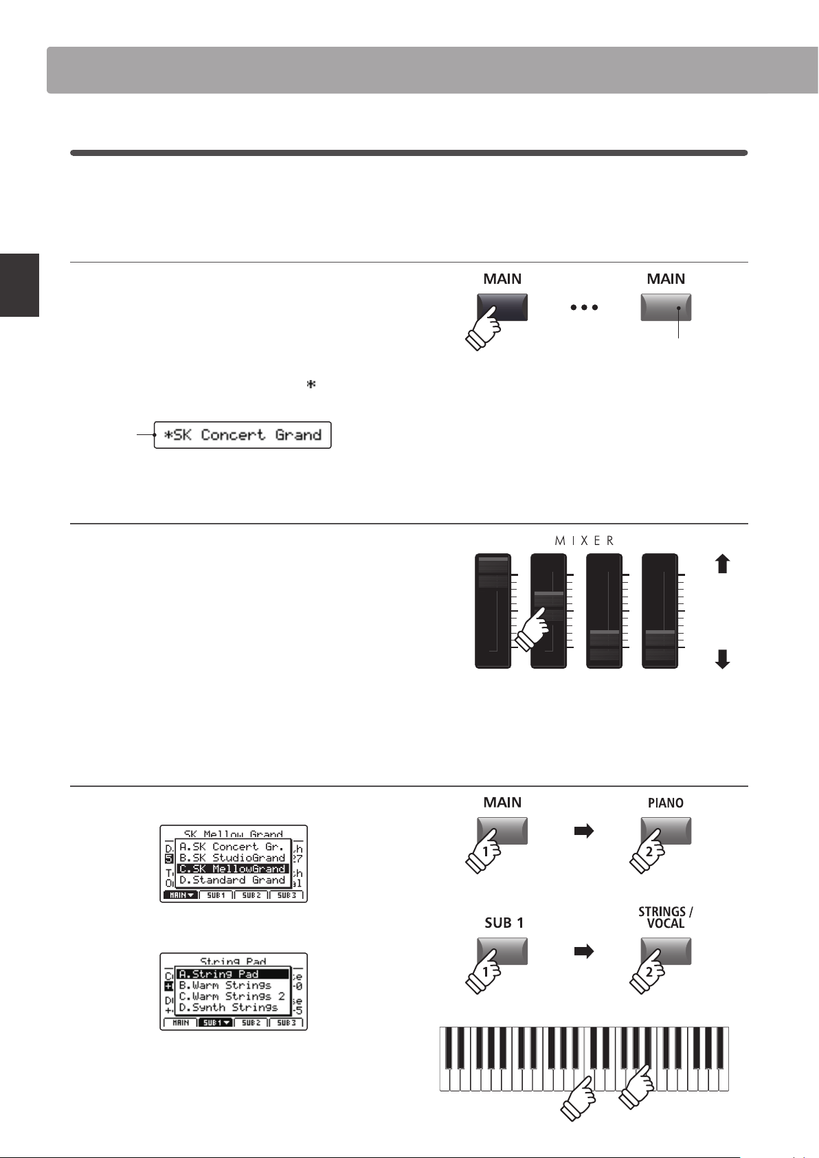
Adjusting the zone volume
Use the VOLUME fader above each zone button to adjust the
volume of that zone.
The volume of the zone will increase or decrease independently
of the other zones.
* When playing with just a single zone (e.g. MAIN), it is recommended to set
the volume fader to the maximum position and use the MASTER volume
fader to adjust the overal volume of the instrument.
To adjust the volume of all sound sections simultaneously, use
the MASTER VOLUME fader (page 12).
Creating a simple two zone layer
First, turn the MAIN zone ON, then select a piano sound.
Next, turn the SUB1 zone ON, and select a strings sound.
Play the layered piano and strings sound, adjusting the MAIN
and SUB1 volume faders to set the level of each sound.
LED indicator ON:
Zone is turned ON
Increase
volume
Decrease
volume
Zone Functions
* When a zone is turned OFF, information for the previously selected (or
neighbouring) zone will be shown in the LCD display.
* When Receive Mode (page 110) is set to ‘Multi’, the MIDI input signal will
still trigger sounds even when a zone is turned OFF.
* When tonewheel organ mode is selected and the sound edit screen shown
in the LCD display, these VOLUME faders are used to adjust the drawbar
positions of the organ. For more information please refer to page 32.
23
Main Operation
2
Zone Modes (int/ext/both)
Also noted in the introduction, the MP7SE’s four zones can each be set to control the instrument’s internal sounds
(INT), external MIDI devices (EXT), or both internal and external simultaneously (BOTH). This page will outline the
dierences between the zone modes, and explain how to switch between them.
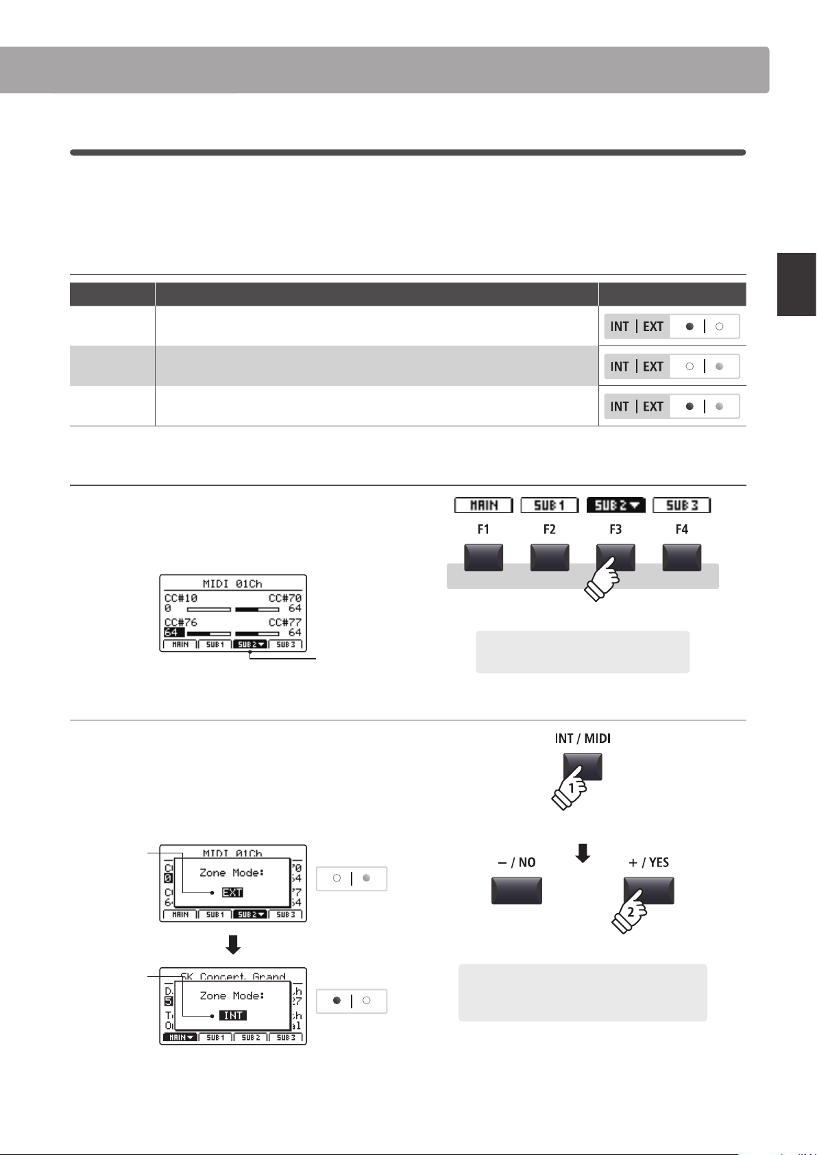
Zone modes
Zone mode Description Panel Appearance
INT The zone will control internal sounds only.
EXT The zone will control external MIDI devices only.
BOTH The zone will control both internal sounds and external MIDI devices simultaneously.
Selecting zones
Press the F1~F4 function buttons located below the LCD display
to select the desired zone.
The selected zone will be shown in the LCD display.
SUB2 zone
selected
Changing the zone mode
Press and hold the INT/MIDI button, then press the +/YES or –/
NO buttons to cycle through the dierent zone modes.
The LED indicator for the zone will change to indicate the
selected zone mode, and the Zone Mode pop-up will briey be
shown in the LCD display.
Before:
EXT mode
Zone LED
After:
INT mode
Zone LED
* By default, the MAIN and SUB1 zones will be set to INT mode, and the SUB2
and SUB3 zones will be set to EXT mode.
Example: To select the SUB2 zone, press the
F3 function button.
hold
Example: To change the SUB2 zone from EXT mode to
INT mode, press and hold the INT/MIDI button, then
press the +/YES button twice.
× 2
Zone Functions
24
Main Operation
3
Zone Key Range
By default, the four zones will each utilise all 88-key of the MP7SE’s keyboard. However, by using the Key Range
function it is possible to create custom keyboard ranges (between two dened keys) for each zone, allowing a
selection of internal sounds or external MIDI devices to be controlled by dierent parts of the keyboard.
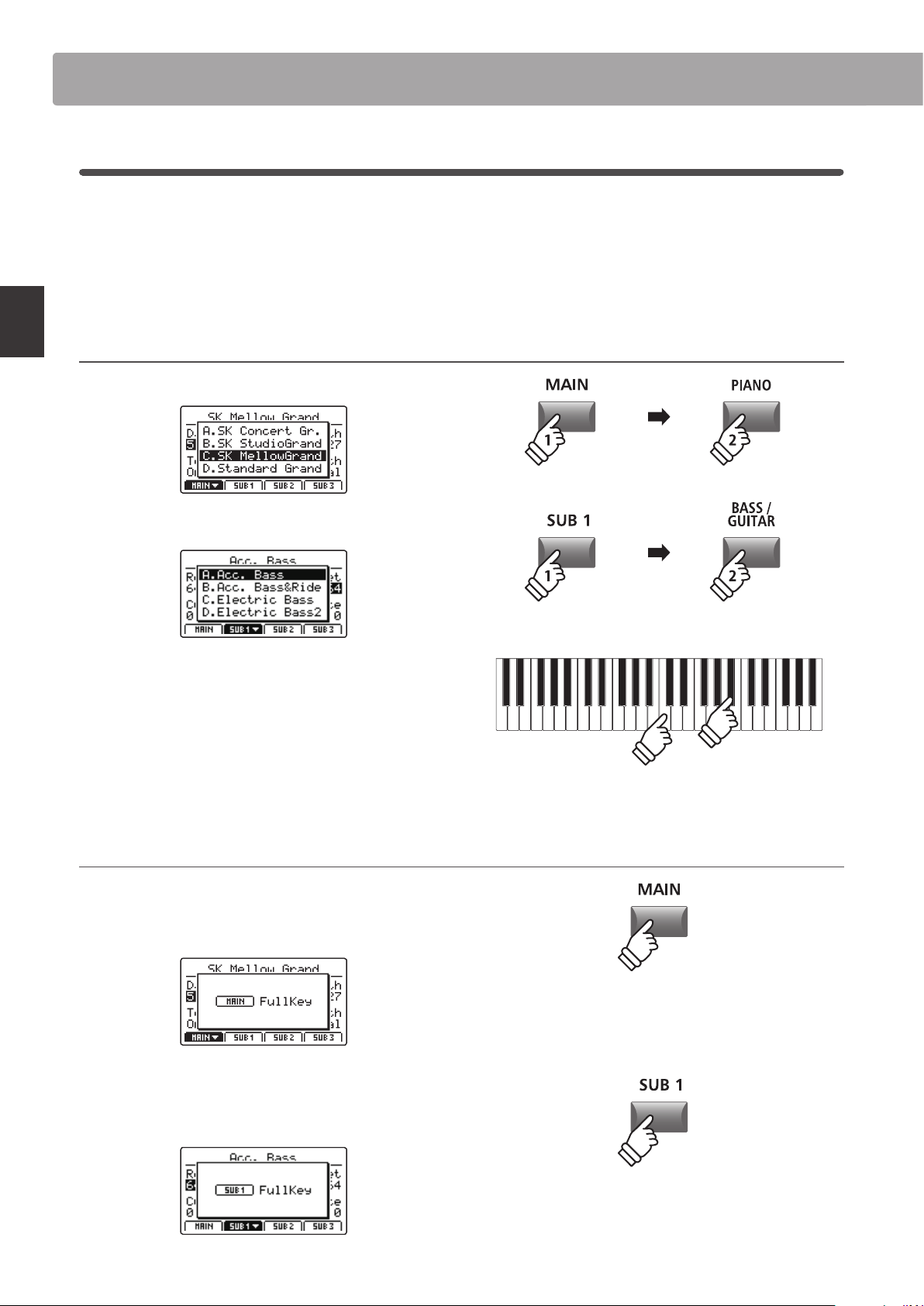
* The example below will explain how to specify key ranges for just the MAIN and SUB1 zones (with a piano sound and acoustic bass sound assigned to the
two zones), however the process is identical for all four zones.
1. Selecting sounds for the MAIN and SUB1 zones
First, turn the MAIN zone ON, then select a piano sound.
Next, turn the SUB1 zone ON, and select a bass sound.
Play the piano.
The piano sound will be layered with the bass sound because
both the MAIN and SUB1 zones are set to use the full keyboard.
The next step is to specify key ranges for the two zones, allowing
the piano and bass sounds to be played independently.
Checking the zone key range
Press and hold the MAIN button.
The current key range for the MAIN zone will be shown in the
LCD display.
Next, press and hold the SUB1 button.
The current key range for the SUB1 zone will be shown in the
LCD display.
hold
hold
Zone Functions
25
Main Operation
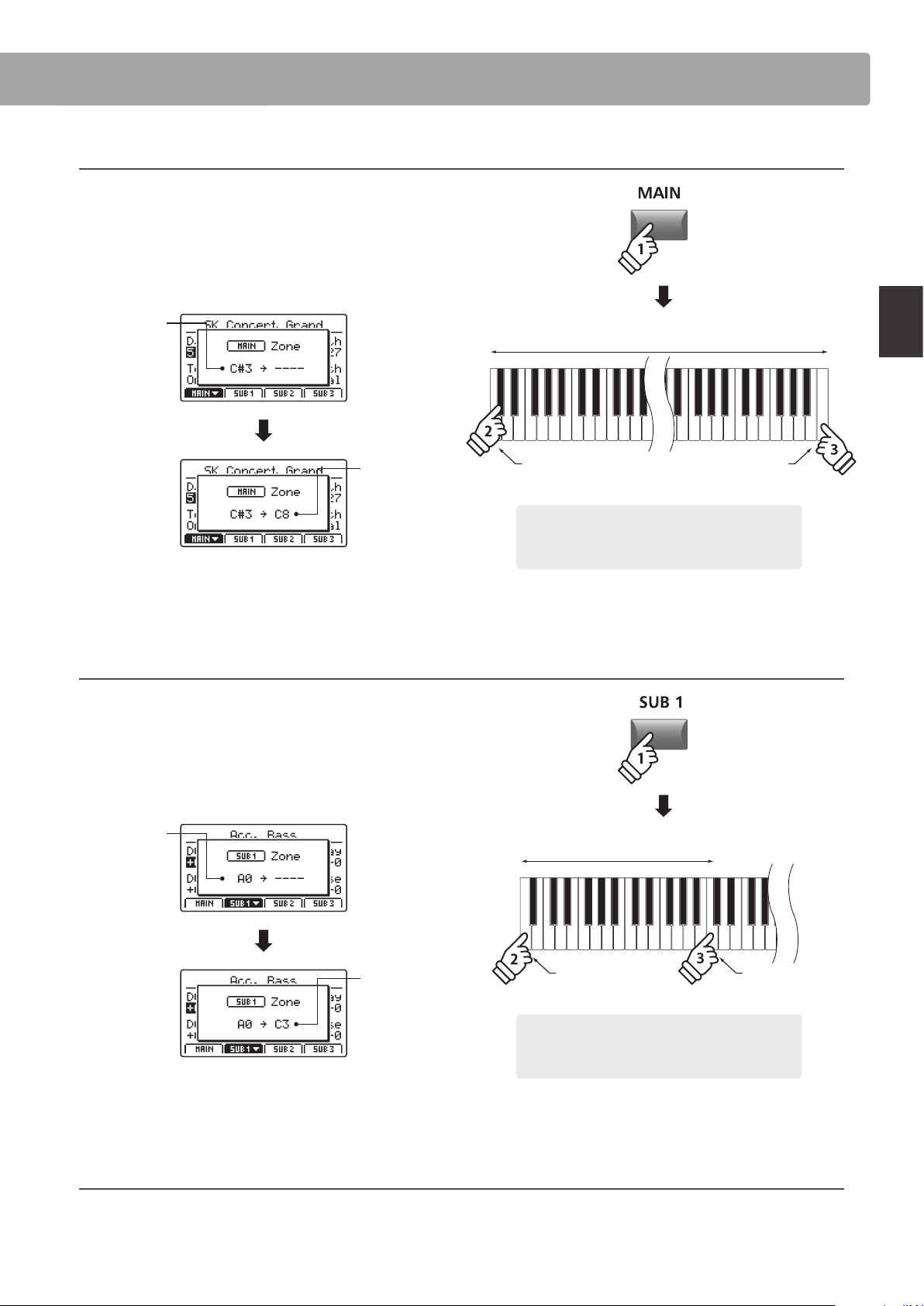
2. Setting the MAIN zone key range
Press and hold the MAIN button, then press the desired low key,
followed by the desired high key for the zone.
The names of the pressed low and high keys will be shown in
the LCD display, and will become the new key range for the
MAIN zone.
Low key:
C#3
High key:
C8
The LED indicator for the MAIN button will also turn green to
indicate that a key range has been set.
3. Setting the SUB1 zone key range
Press and hold the SUB1 button, then press the desired low key,
followed by the desired high key for the zone.
The names of the pressed low and high keys will be shown in
the LCD display, and will become the new key range for the
SUB1 zone.
Low key:
A0
High key:
C3
The LED indicator for the SUB1 button will also turn green to
indicate that a key range has been set.
4. Playing the MAIN and SUB1 zone key ranges
Test the new zone key ranges by playing a chromatic scale from the bottom-most note of the keyboard. The bass sound will be heard
from the bottom-most key to the C3 key, and the piano sound will be heard from the C#3 key to the top-most key. This bass/piano
conguration is a popular combination for playing jazz standards.
Example: To set the MAIN zone key range between key
C#3 and C8, press and hold the MAIN zone button,
then press the C#3 key, followed by the C8 key.
* It is also possible to set the zone key range using the KeySetup parameters
in the EDIT menu. For more information, please refer to page 47.
hold
Example: To set the SUB1 zone key range between key
A0 and C3, press and hold the SUB1 zone button, then
press the A0 key, followed by the C3 key.
hold
Low key: A0 High key: C3
Zone key range
* It is also possible to set the zone key range using the KeySetup parameters
in the EDIT menu. For more information, please refer to page 47.
Low key: C#3
Zone key range
High key: C8
Zone Functions
26
Main Operation
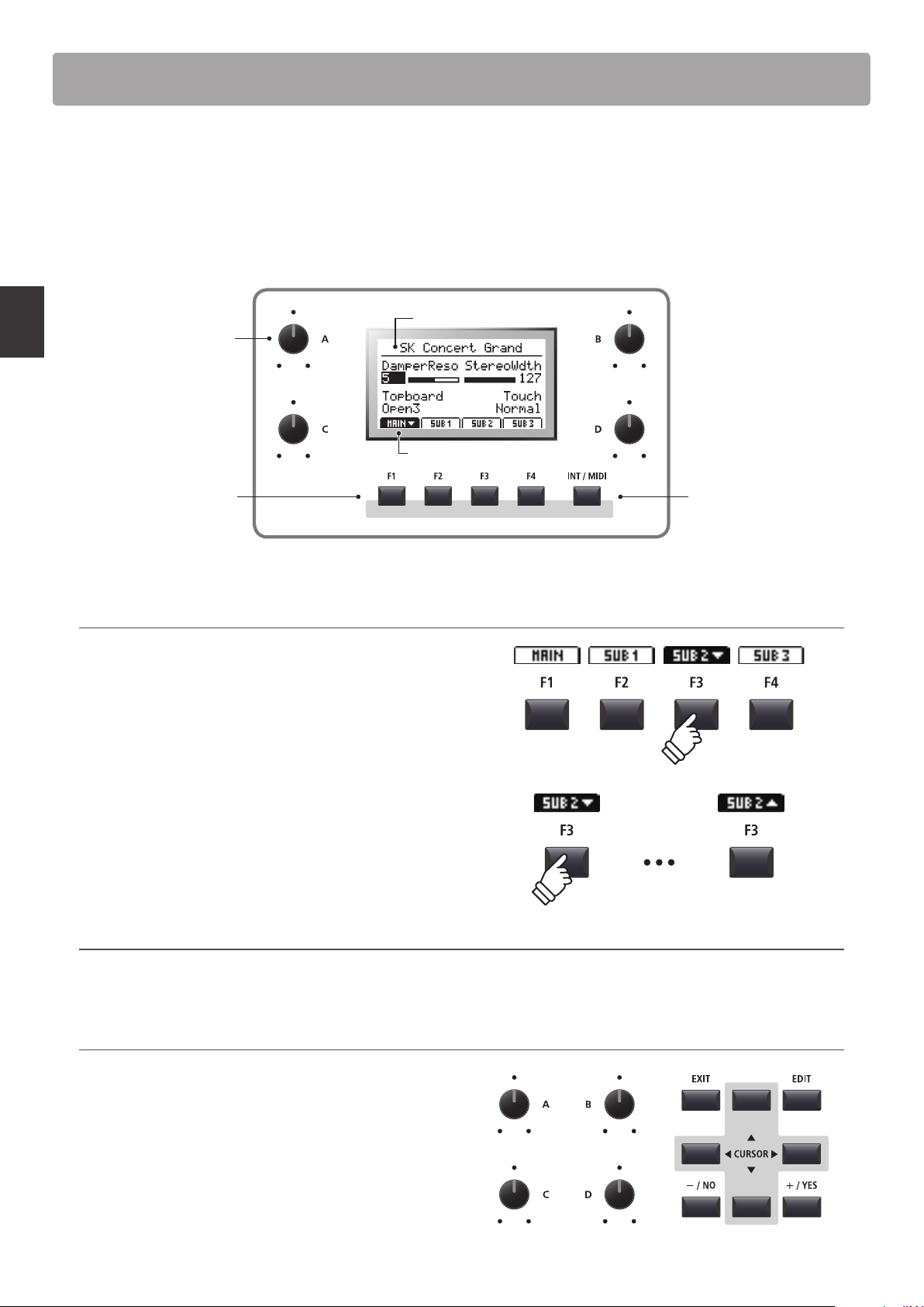
In regular Play Mode the LCD display provides a visual indication of the selected zone and sound, and the values of
the four real-time control knobs (A, B, C, and D).
The function of each knob can be assigned to control any parameter in the EDIT menu, allowing frequently used
functions to be accessed from a single screen. Furthermore, two groups of knob parameters (2 x 4) can be dened
for each of the MAIN, SUB1, SUB2, and SUB3 zones, providing extensive real-time control.
Control knobs:
Adjust value of assigned
parameters or settings.
Function buttons:
Select zone and various
other operations.
Selected sound
Selected zone/knob group
INT/MIDI button:
Toggle between zone
modes (INT/EXT/BOTH).
Please refer to page 23.
Selecting zones, primary/secondary knob groups
Press the F1~F4 function buttons located below the LCD display
to select the desired zone.
The bottom tab representing the zone will become highlighted,
and the name of the selected sound and primary group of knob
parameters will be shown in the LCD display.
Press the same function button to cycle between the zones’
primary and secondary knob parameters in the LCD display.
* While in the EDIT menu, pressing the same F1~F4 FUNCTION button will
scroll through the dierent parameter pages.
Changing zones modes (INT/MIDI button)
For information about changing zone modes, please refer to page 23.
Adjusting parameters
Turn the four control knobs (A, B, C, D) located on either side of
the LCD display to adjust the displayed knob group parameters.
* EDIT menu parameters can be freely assigned to each of the four knobs in
the Knob Assign page of the EDIT menu (page 51).
Parameters can also be adjusted by using the CURSOR buttons
to move the selection cursor, and +/YES or –/NO buttons to
increase or decrease the value of the selected parameter.
Primary Secondary
LCD Display & Control Knobs
27
Main Operation
Eects Section
1
Reverb
Reverb adds reverberation to the sound, simulating the acoustic environment of a recital room, stage, or concert
hall. The MP7SE oers 6 types of high quality reverb, with independent ON/OFF and depth controls for each zone.
The reverb type, pre-delay, and time parameters, however, are common for all zones.
* For more information about common parameters, please refer to page 38.
Reverb types
Reverb type Description
Room Simulates the ambiance of a small rehearsal room.
Lounge Simulates the ambience of a piano lounge.
Small Hall Simulates the ambiance of a small hall.
Concert Hall Simulates the ambiance of a concert hall or theater.
Live Hall Simulates the ambiance of a live hall or stage.
Cathedral Simulates the ambiance of a large cathedral.
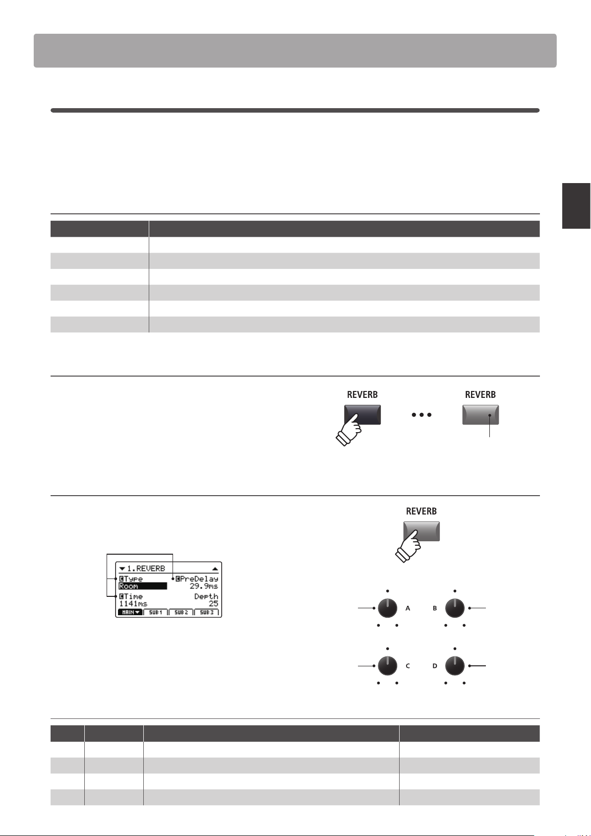
Turning reverb ON or OFF
Press the REVERB button for the desired zone to turn reverb for
that zone ON or OFF.
The LED indicator for the zone’s REVERB button will turn ON or
OFF to indicate the current status of the reverb.
Changing the reverb type and additional parameters
Press and hold the REVERB button for the desired zone.
The REVERB page of the zone’s EDIT menu will be shown in the
LCD display.
Common
parameters:
See page 38
Turn the four control knobs (A, B, C, D) to change the reverb type
and adjust additional reverb parameters.
Press and hold the REVERB button again to exit.
Reverb parameters
Knob Parameter Description Value range
A Type Changes the type of environment. (see table above)
B PreDelay Adjusts the delay time before the reverberation is applied. 0 ~ 200 ms
C Time Adjusts the decay length/speed of the reverberation. 300 ms ~ 10.0 s
(depending on type)
D Depth Adjusts the depth of the environment (amount of reverberation). 0 ~ 127
Time
Type
Depth
PreDelay
LED indicator ON:
Reverb is turned ON
hold
28
Main Operation
2
EFX
In addition to reverb, various other eects can be applied to each zone, altering the tonal character and feeling of
the selected sound. The MP7SE features 129 high quality EFX types, with eects automatically applied to some
sounds by default in order to enhance their realism.
As noted in the introduction chapter, the MAIN and SUB1/SUB2/SUB3 zones share largely the same EFX operation,
however there are some important specication and capability dierences between the two zone types.
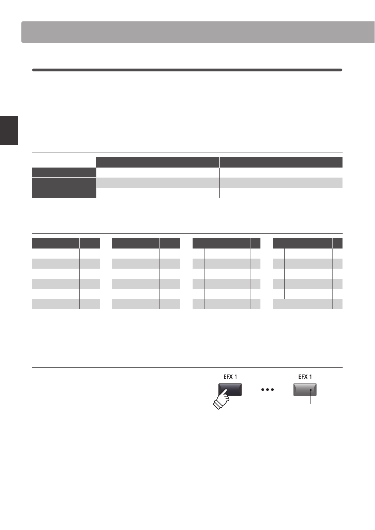
EFX specications: MAIN and SUB1/SUB2/SUB3 zones
MAIN zone SUB1/SUB2/SUB3 zones
No. of EFX blocks 2 (applied in serial, independently adjustable) 1 each (independently adjustable)
No. of available eects 129 t ypes 22 types
Amp Simulator Yes No
Available eect types: MAIN vs SUB1/SUB2/SUB3 zones
EFX category M S EFX category M S EFX category M S EFX category M S
1 Chorus 8 2 7 Delay/Rev 8 2 13 Groove 4 1 19 Enhancer+ 8 -
2 Flanger 5 2 8 PitchShift 3 1 14 Misc. 2 - 20 P. S hif t+ 6 -
3 Phaser 6 1 9 Compressor 2 1 15 Chorus+ 6 - 21 Comp+ 8 -
4 Wah 6 3 10 OverDrive 3 2 16 Phaser+ 6 - 22 OverDrive+ 8 -
5 Tremolo 6 3 11 EQ/Filter 5 2 17 Wah+ 6 - 23 Parallel 6 -
6 AutoPan 4 1 12 Rotary 5 1 18 EQ+ 8 - TOTAL 129 22
* The ‘+’ eects consist of the base eect plus an additional combination eect, while still using only one eect module.
* For more information about available eect categories, types, and parameters, please refer to page 128.
Turning eects ON or OFF
Press the EFX button for the desired zone to turn eects for that
zone ON or OFF.
The LED indicator for the zone’s EFX button will turn ON or OFF
to indicate the current status of the eects.
* The MAIN zone’s EFX1 and EFX2 modules and SUB1/SUB2/SUB3 zones’ EFX
modules are turned ON and OFF in exactly the same way.
Eects Section
LED indicator ON:
Eects are turned ON
29
Main Operation
Changing the eect category, type and additional parameters
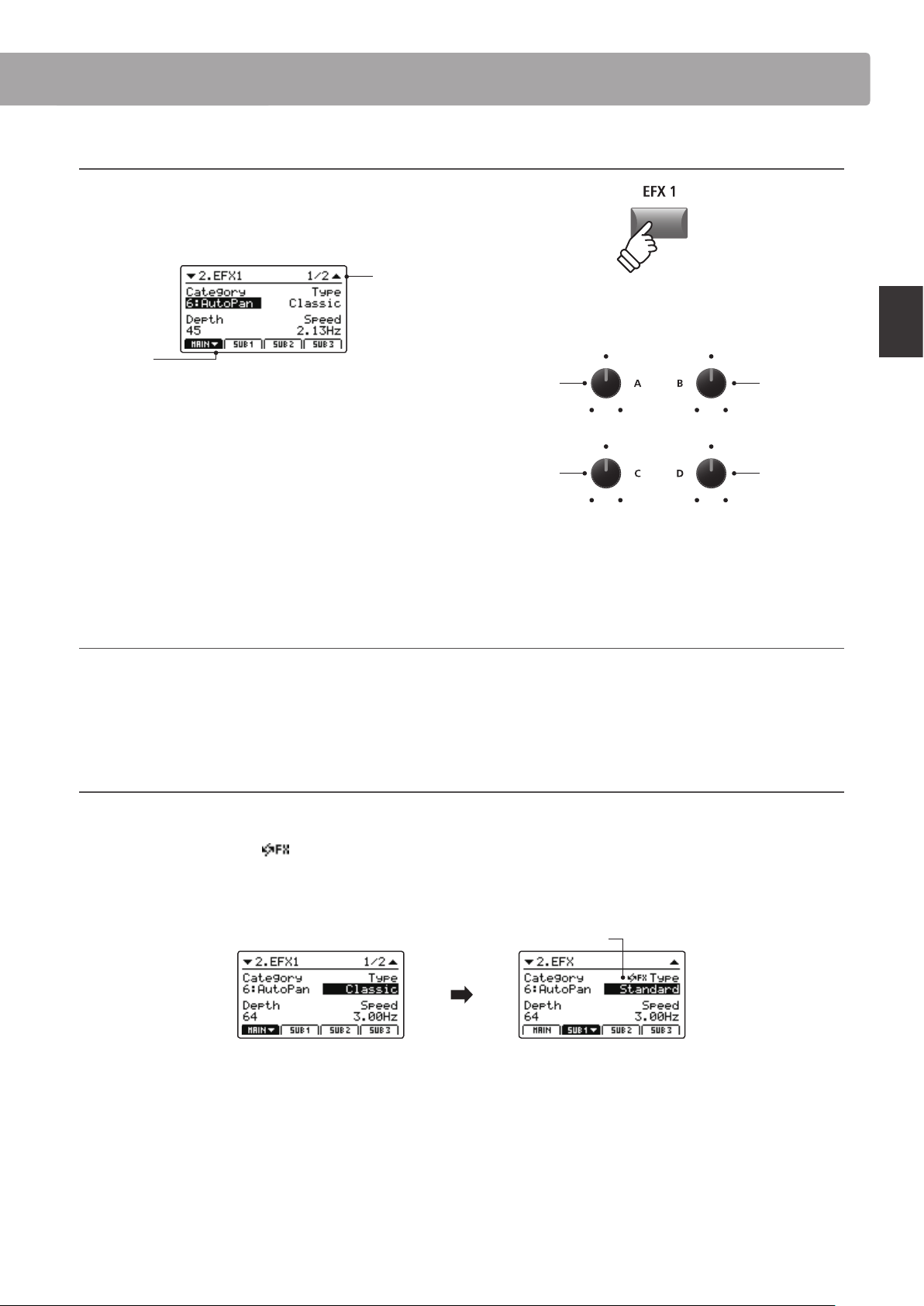
Press and hold the EFX button for the desired zone.
The rst EFX page of the zone’s EDIT menu will be shown in the
LCD display.
Page 1/2
arrow:
Next page
Turn the control knobs (A, B, C, D) to change the eect category,
type, and adjust additional eect parameters.
* The number of adjustable EFX parameters will vary depending on type.
For more information, please refer to page 128.
* Press the F1~F4 FUNCTION buttons (corresponding to the selected zone)
to scroll through the dierent parameter pages.
Press and hold the EFX button again to jump to the rst EFX
page of the EDIT menu, and once again to EXIT.
E.SW Mode parameter (SYSTEM menu)
The E.SW Mode parameter in the SYSTEM:Utility menu denes the extent to which EFX and other settings change when selecting sounds.
When this parameter is set to ‘Fixed’ mode, it is possible to copy the same EFX settings to multiple sounds.
* For more information about the E.SW Mode parameter, please refer to page 106.
About Substitute eects for SUB1/SUB2/SUB3 zones
As noted above, the total number of eect types available for the MAIN zone is much larger than that of the SUB zones. Therefore, when
assigning a sound to a SUB zone that was prepared using an eect only available for the MAIN zone, the MP7SE will automatically select
the closest ‘substitute’ eect. An
icon will also be shown beside the type parameter to indicate that a substitute eect is being used.
The example below shows the ‘Classic’ AutoPan eect being substituted for the ‘Standard’ AutoPan eect.
* Only the EFX1 eect will be substituted. Any eects that are assigned to EFX2 will be disregarded.
MAIN zone EFX1 screen
A sound prepared on the
MAIN zone with ‘Classic’
AutoPan eect applied.
SUB1 zone EFX screen
The same sound assigned
to SUB1 zone, ‘Standard’
AutoPan eect is
automatically substituted.
Substitute eect icon
Parameter 1
Category
Parameter 2
Type
* Above knob assignments will change depending on EFX page displayed.
hold
Eects Section
30
Main Operation
3
Amp Simulator (MAIN zone only)
The tonal character of an amplier or speaker cabinet is an important component of vintage electric piano sounds.
The MP7SE’s Amp Simulator function features 5 typical amplier types and a selection of adjustable parameters.
Amp types
Amp type Description
S. Case A suitcase type amplier, commonly used for vintage electric piano sounds.
M. Stack A British valve guitar amplier, known for its ‘crunchy’ tonal character.
J. Combo A popular Japanese solid-state amplier favoured for its clean, yet powerful sound.
F. Bass An American valve bass amplier that became popular for guitar, harmonica, and other instruments.
L. Cabi
A valve amplier and speaker enclosed within a wooden cabinet, originally intended for drawbar organ
sounds, but also used with electric pianos to produce a distinctive ‘shimmering’ sound.
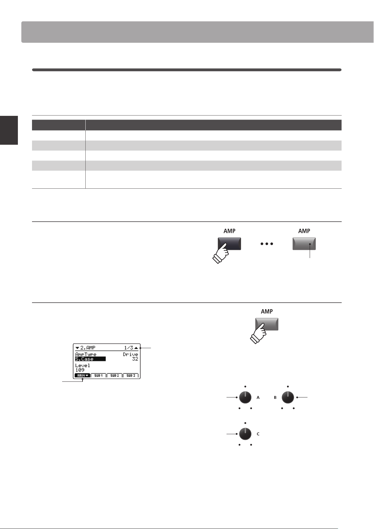
Turning the Amp Simulator ON or OFF
Press the MAIN zone’s AMP button to turn the amp simulator
ON or OFF.
The LED indicator for the AMP button will turn ON or OFF to
indicate the current status of the amp simulator.
Changing the Amp type, adjusting drive, and level parameters
Press and hold the MAIN zone’s AMP button.
The rst AMP page of the EDIT menu will be shown in the LCD
display.
Page 1/3
arrow:
Next page
Turn the control knobs (A, B, C) to change the amp type, and
adjust the drive and level parameters.
* For more information about additional Amp Simulator parameters, please
refer to page 41.
* Press the F1 FUNCTION buttons (corresponding to the MAIN zone) to scroll
through the dierent AMP parameter pages.
Press and hold the AMP button again to jump to the rst AMP
page of the EDIT menu, and once again to EXIT.
Level
Amp Type
Drive
* Above knob assignments will change depending on AMP page displayed.
Eects Section
LED indicator ON:
Amp Simulator is turned ON
hold
31
Main Operation
Amp Simulator parameters
Page Knob Parameter Description Value range
1
A Amp Type Changes the type of amplier model. [see table above]
B Drive Adjusts the drive level of the amplier. 0 ~ 127
C Level Adjusts the overall volume level of the amplier. 0 ~ 127
2
A Amp EQ Lo Adjusts the gain of the amplier’s low frequencies. –10 dB ~ +10 dB
B Amp EQ Mid Adjusts the gain of the amplier’s mid frequencies. –10 dB ~ +10 dB
C Amp EQ Hi Adjusts the gain of the amplier’s high frequencies. –10 dB ~ +10 dB
D Mid Frequency Adjusts the frequency of the amplier’s mid-range band. 200 Hz ~ 3150 Hz
3
A Mic Type Changes the type of microphone used for the amplier. Condenser, Dynamic
B Mic Position Change the position of the microphone used for the amplier. OnAxis, OAxis
C Ambience Adjusts the mixing ratio of additional ambient microphones. 0 ~ 127
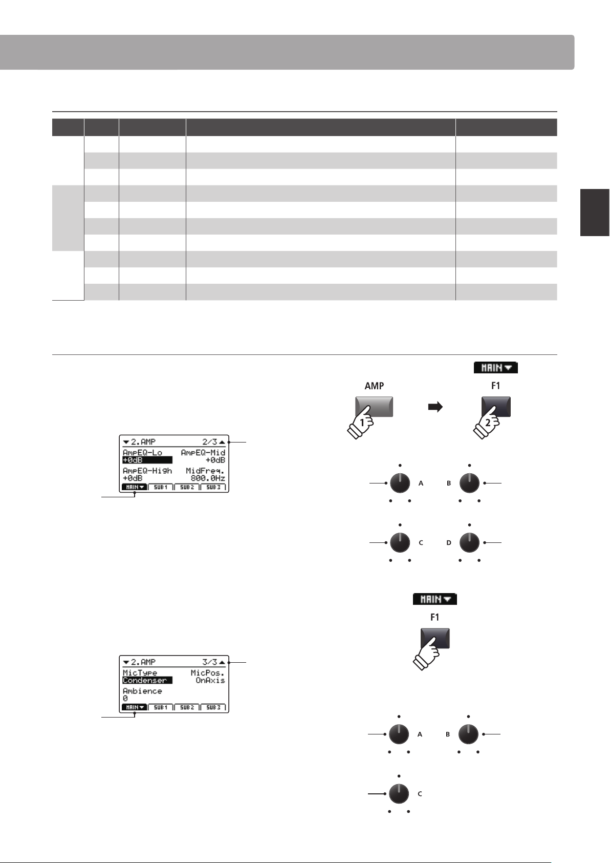
Adjusting additional Amp Simulator parameters
Press and hold the MAIN zone’s AMP button, then press the F1
FUNCTION button (corresponding to the selected MAIN zone).
The second AMP page of the EDIT menu will be shown in the
LCD display.
Page 2/3
arrow:
Next page
Turn the control knobs (A, B, C, D) to adjust the amp simulator’s
Lo, Mid, Hi, and MidFreq EQ parameters.
Press the F1 button again.
The third AMP page of the EDIT menu will be shown in the LCD
display.
Page 3/3
arrow:
Next page
Turn the control knobs (A, B, C) to change the type and
positioning of the amp simulator’s microphone, and adjust the
ambience parameter.
Amp EQ Hi
Amp EQ Lo
Mid Freq.
Amp EQ Mid
Ambience
Mic Type
Mic Position
hold
Eects Section
32
Main Operation
The MP7SE’s tonewheel mode is a special function that transforms the instrument into a vintage electromechanical
organ, complete with drawbar, percussion, and slow/fast rotary speaker controls. Tonewheel mode is only available
for the MAIN zone, and activated when selecting the DRAWBAR sound category and 1, 2, or 3 sub-categories.
Upon activating tonewheel mode and selecting the tonewheel edit screen, the MP7SE’s zone faders will act as virtual
organ drawbars, with the MAIN, SUB1, SUB2, and SUB3 zone buttons also used to change percussion functions.
1. Activating tonewheel organ mode
After selecting the MAIN zone:
Press the DRAWBAR sound category button, then press either
the 1, 2, or 3 sub-category buttons.
The LED indicators for the pressed buttons will turn ON, and the
selected tonewheel sound will be shown in the LCD display.
Selected
tonewheel
sound
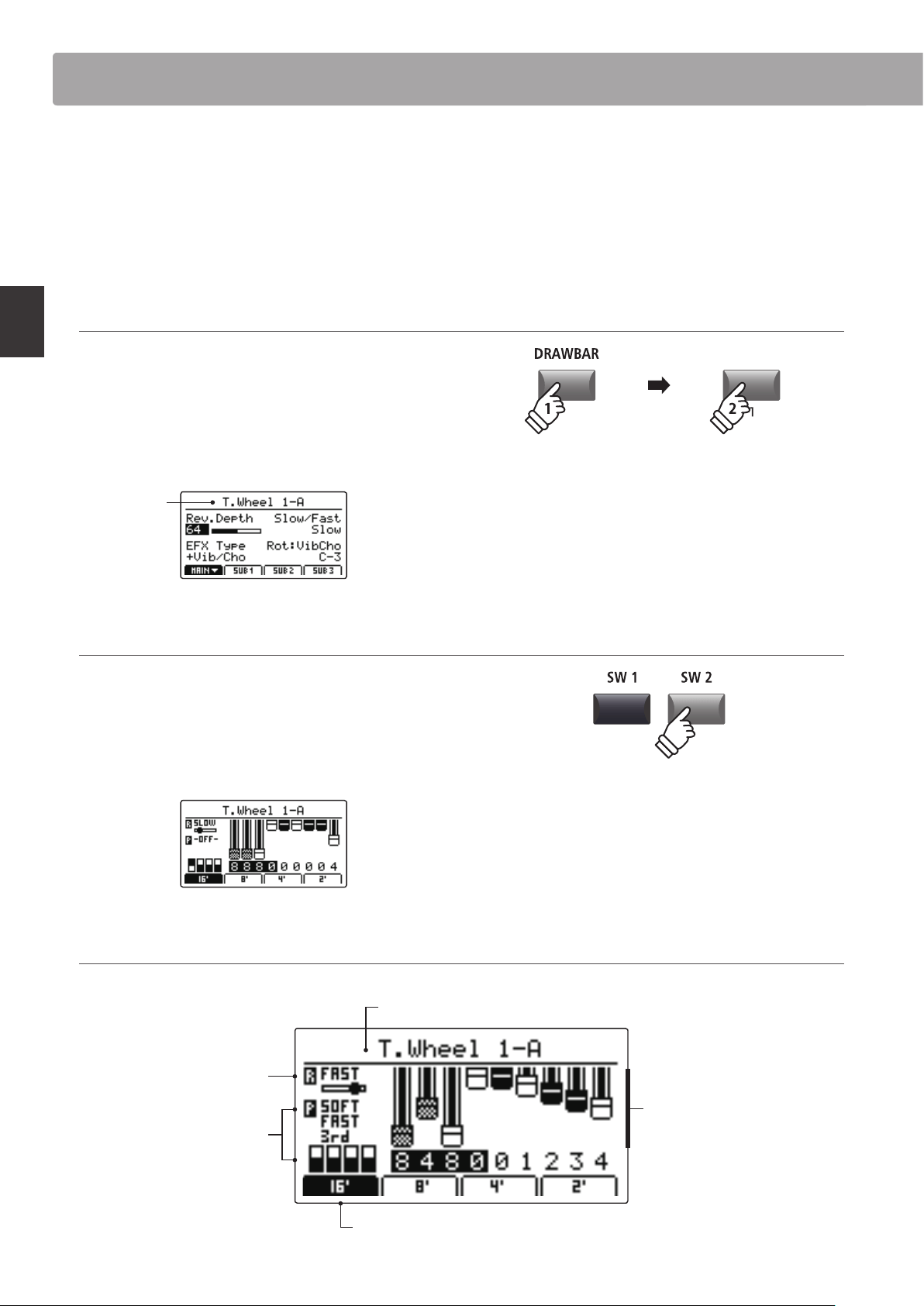
2. Showing the tonewheel edit screen
Press the SW2 button.
The LED indicator for the SW2 button will turn on and the
tonewheel edit screen will be shown in the LCD display.
* The tonewheel edit screen can also be shown by selecting the Sound page
of the EDIT menu when tonewheel mode is activated.
Tonewheel edit screen
* The tonewheel organ drawbars can
also be adjusted via MIDI. For more
information, please refer to page 44.
Selected tonewheel sound:
Stored to DRAWBAR sounds 1-3, A-D.
Rotary speed:
Indicates slow or fast rotary.
Toggled by the SW1 button or
FSW pedal.
Percussion setting:
Adds percussive ‘attack’ to
the organ sound. Adjusted
using the zone buttons.
Selected drawbar group:
Indicates which drawbars will be adjusted using the zone faders and control knobs.
Drawbar registration:
Visual representation of the
organ’s drawbar positions.
Adjusted using the zone
faders and control knobs.
* The tonewheel mode can only be selected for the MAIN zone. When a SUB
zone is selected and the DRAWBAR 1/2/3 buttons are pressed, a pop-up
reminder will be shown and the selected sound will remain unchanged.
* If the assigned function of the SW2 button is changed from the default ‘TW
Control’, the tonewheel edit screen will not be shown.
* For information about changing the assigned SW1/SW2 function, please
refer to page 49.
Tonewheel Organ Mode
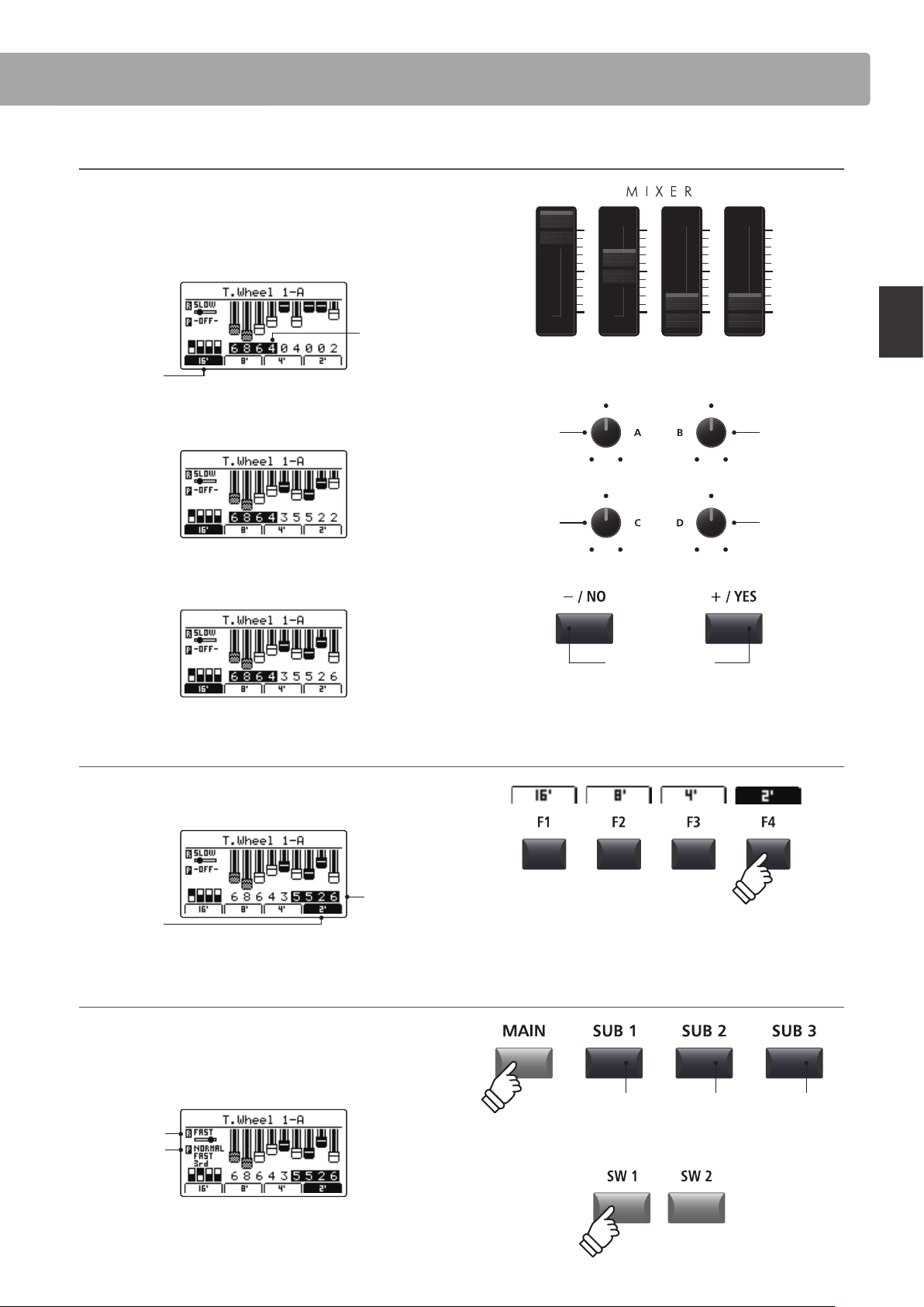
33
Main Operation
Adjusting the organ’s drawbar registration
While the tonewheel edit screen is shown in the LCD display, and
the 16’ drawbar group tab is selected:
Use the zone faders to adjust the position of the rst four organ
drawbars.
16’ drawbar
group
selected
drawbars
adjusted by
zone faders
Turn the control knobs (A, B, C, D) to adjust the position of the
next four organ drawbars.
Finally, press the +/YES or –/NO buttons to adjust the position of
the last organ drawbar.
Changing the selected drawbar group
Press the F1~F4 function buttons to select which four drawbars
are adjusted by the zone faders.
2’ drawbar
group
selected
drawbars
adjusted by
zone faders
Changing organ percussion settings and rotary eect speed
While the tonewheel edit screen is shown in the LCD display:
Press the MAIN button to turn percussion ON or OFF, and the
SUB buttons to adjust the percussion characteristics.
Percussion
enabled
Fast rotary
Press the SW1 button or FSW pedal to change the speed of the
rotary eect from slow to fast.
MAIN:
16’
SUB1:
5 ⁄’
SUB2:
8’
SUB3:
4’
Knob C:
1 ⁄’ drawbar
Knob A:
2 ⁄’ drawbar
Knob D:
1 ⁄’ drawbar
Knob B:
2’ drawbar
Drawbar:
–/NO or +/YES:
1’ drawbar
* The control knob and –/NO and +/YES button drawbar assignments will
change depending on the selected zone faders.
Volume:
Normal / Soft
Speed:
Slow / Fast
Harmonic:
2nd / 3rd
Tonewheel Organ Mode
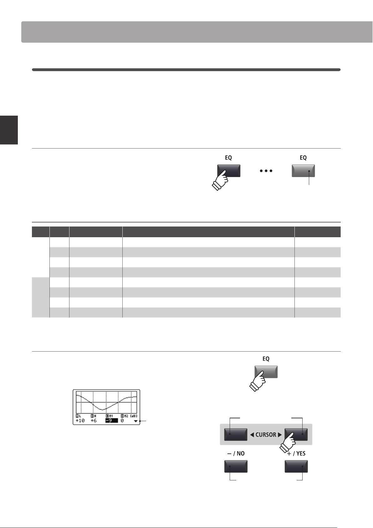
34
Main Operation
1
EQ
The EQ function consists of a 4-band graphic equaliser that can be used to shape the overall tone of the MP7SE’s
internal sounds. Two of the mid-range frequency bands can also be adjusted as a parametric equaliser.
The equaliser settings are common for all zones.
* For more information about common parameters, please refer to page 38.
Turning EQ ON or OFF
Press the EQ button to turn the MP7SE’s equaliser ON or OFF.
The LED indicator for the EQ button will turn ON or OFF to
indicate the current status of the equaliser.
EQ parameters
Page Knob Parameter Description Value range
1
A Low Gain Adjusts the gain of the low range frequency band (20 ~ 100 Hz). –10 dB ~ +10 dB
B High Gain Adjusts the gain of the high range frequency band (5000 ~ 20000 Hz). –10 dB ~ +10 dB
C Mid1 Gain Adjusts the gain of the Mid1 frequency band (200 ~ 3150 Hz). –10 dB ~ +10 dB
D Mid2 Gain Adjusts the gain of the Mid2 frequency band (200 ~ 3150 Hz). –10 dB ~ +10 dB
2
A Mid1 Q Adjusts the bandwidth of the Mid1 band. 0.5 ~ 4.0
B Mid2 Q Adjusts the bandwidth of the Mid2 band. 0.5 ~ 4.0
C Mid1 Freq. Adjusts the frequency of the Mid1 band. 200 Hz ~ 3150 Hz
D Mid2 Freq. Adjusts the frequency of the Mid2 band. 200 Hz ~ 3150 Hz
Adjusting EQ parameters
Press and hold the EQ button.
The gain page of the EQ will be shown in the LCD display.
Next
page
Press the CURSOR buttons to select the desired EQ
parameter, then press the +/YES or -/NO buttons to increase or
decrease the values.
Alternatively, turn the control knobs (A, B, C, D) to adjust the EQ
parameter assigned to that knob.
* The F1~F4 buttons can also be used to select the desired EQ parameter.
If the parameter is already selected, the F1~F4 buttons can be used to
alternate between the gain and frequency pages of the EQ.
LED indicator ON:
Equaliser is turned ON
hold
Decrease/Increase values
Select EQ parameter
Global Section
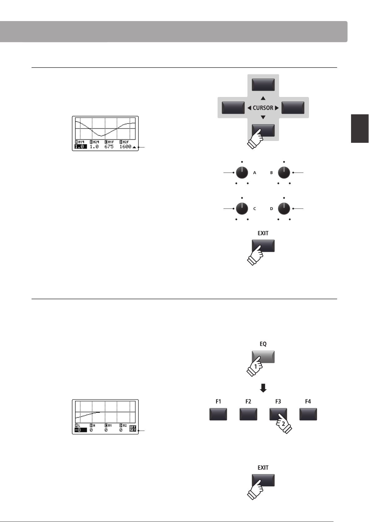
35
Main Operation
Adjusting EQ parameters (cont.)
While the gain page of the EQ is shown:
Press the CURSOR button.
The frequency page of the EQ will be shown in the LCD display.
Previous
page
Press the CURSOR buttons to select the desired EQ
parameter, then press the +/YES or -/NO buttons to increase or
decrease the values.
Alternatively, turn the control knobs (A, B, C, D) to adjust the EQ
parameter assigned to that knob.
Press the EXIT button to return to the main playing screen.
Jump to EQ Oset shortcut
The EQ Oset is a SYSTEM parameter used to oset adjustments made by the EQ. The purpose of the EQ Oset is to
allow a ‘baseline’ EQ to be applied independently of the EQ function, and therefore independently of the selected
SETUP. EQ Oset must be enabled in the SYSTEM menu for this shortcut to function.
* For more information about the EQ Oset function, please refer to page 111.
To jump to the EQ Oset screen, at any time:
Press and hold the EQ button, then press one of the F1~F4
buttons.
The EQ Oset screen will be shown in the LCD display.
Oset
page
The EQ Oset parameters are adjustable in the same manner as
the EQ gain parameters.
* The EQ Oset values will be added to the regular EQ values. The combined
EQ values are limited to ±10 dB.
Press the EXIT button to return to the EQ screen.
Press the EXIT button again to return to the main playing screen.
Mid1
frequency
Mid1
bandwidth
Mid2
frequency
Mid2
bandwidth
hold
Global Section
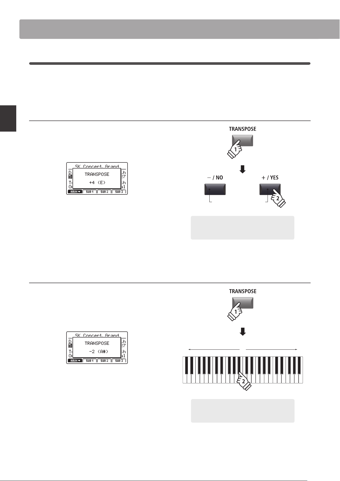
36
Main Operation
2
Transpose
The Transpose function allows the pitch of the MP7SE’s keyboard to be raised or lowered in semi-tone steps. This
is particularly useful when accompanying instruments tuned for dierent keys, or when a song learned in one key
must be played in another key.
Setting the Transpose value: Method 1
Press and hold the TRANSPOSE button, then press the +/YES
or –/NO buttons to increase or decrease the transpose value in
semi-tone steps.
* The TRANSPOSE value can be adjusted within the range of -24 ~ +24.
The LED indicator for the TRANSPOSE button will turn ON
automatically to indicate that transpose is activated.
* To reset the transpose value to 0 (no transposition), press both the –/NO
and +/YES buttons simultaneously. The LED indicator for the TRANSPOSE
button will turn o automatically.
* The transpose value will be stored to SYSTEM memory automatically,
however the transpose ON/OFF state will not be stored.
Setting the Transpose value: Method 2
Press and hold the TRANSPOSE button, then press a key on the
keyboard to the left or right of middle C.
The pressed key will become the new transpose key.
* The TRANSPOSE value can be adjusted within the range of -24 ~ +24.
The LED indicator for the TRANSPOSE button will turn ON
automatically to indicate that transpose is activated.
* To reset the transpose value to 0 (no transposition), press both the –/NO
and +/YES buttons simultaneously. The LED indicator for the TRANSPOSE
button will turn o automatically.
* The transpose value will be stored to SYSTEM memory automatically,
however the transpose ON/OFF state will not be stored.
Global Section
hold
Decrease/Increase values
× 4
Example: To raise the keyboard pitch by 4 semi-tones,
press and hold the TRANSPOSE button, then press the
+/YES button four times.
hold
-24 0 +24
Example: To lower the keyboard pitch by 2 semi-
tones, press and hold the TRANSPOSE button, then
press the B
b
key closest to the middle C key.
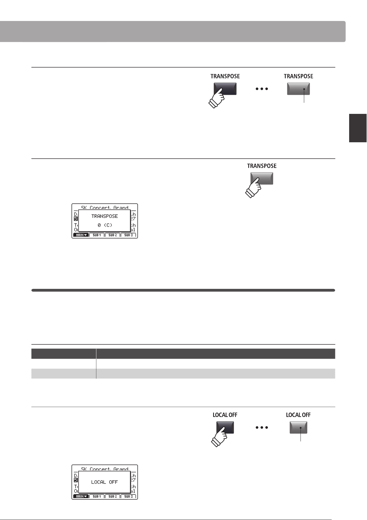
37
Main Operation
Turning Transpose ON or OFF
Press the TRANSPOSE button to turn the transpose function ON
or O FF.
The LED indicator for the TRANSPOSE button will turn ON or
OFF to indicate the current status of the transpose function.
* The previous transpose setting will be remembered after the transpose
function is turned OFF, allowing rapid adjustment of the keyboard pitch.
Checking the Transpose setting
Press and hold the TRANSPOSE button.
The current transpose setting will pop-up in the LCD display.
* The default value, 0, indicates no transposition.
3
Local O
The Local O function allows the connection between the MP7SE’s keyboard and tone generator to be disabled.
This may be useful when using the MP7SE to control an external MIDI device, without the keyboard triggering the
instrument’s internal sounds.
Local function
LOCAL OFF button LED Description
OFF (default) The MP7SE will transmit information to external MIDI devices, and play internal sounds.
ON The MP7SE will transmit information to external MIDI devices only, and not play internal sounds.
Turning the Local function ON or OFF
Press the LOCAL OFF button.
The LED indicator for the LOCAL OFF button will turn ON or OFF
to indicate the current status of the Local function.
The Local status pop-up will briey be shown in the LCD display.
LED indicator ON:
Transpose is turned ON
hold
LED indicator ON:
Local O is turned ON
Global Section
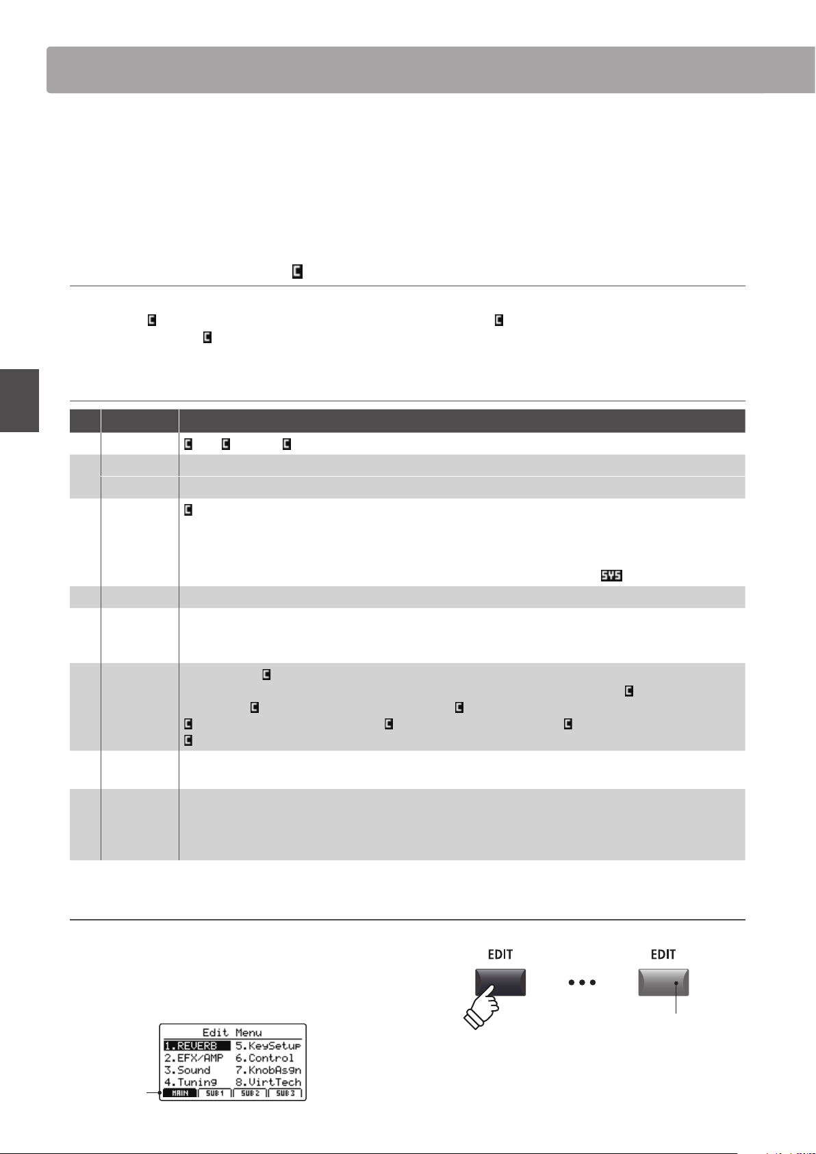
38
EDIT Menu
Overview of the EDIT Menu (INT mode)
The EDIT menu contains various parameters that can be used to adjust the MP7SE’s MAIN and SUB zones in INT mode.
The parameters are grouped by category, allowing close control over the instrument with just a few button presses.
* The EDIT menu can also be used to adjust the parameters of zones in EXT mode. For more information, please refer to page 54.
This collection of parameters, together with other adjustable settings, can be stored as a SETUP memory (page
65). The MP7SE provides 256 user programmable SETUP memories.
About Common parameters ( icon)
Unless stated, parameter settings for the MAIN, SUB1, SUB2, and SUB3 zones are independent for each zone. However, parameters
marked with a
icon are common for all four zones. For example, changing the Reverb Type parameter for the MAIN zone will
automatically change the
Reverb Type parameter for the SUB1, SUB2, and SUB3 zones.
INT mode zone parameters
No. Category Parameters
1 REVERB Type, Pre Delay, Time, Depth
2
EFX Category, Type, Parameters
(prm1~prm10, depending on EFX type)
AMP Amp Type, Drive, Level, Amp EQ Lo, Amp EQ Mid, Amp EQ Hi, Mid Freq., Mic Type, Mic Position, Ambience
3 Sound
Master Volume, Panpot, Filter Cut-o, Filter Resonance, DCA Attack Time, DCA Decay Time, DCA Sustain Level,
DCA Release Time, DCF Attack Time, DCF Attack Level, DCF Decay Time, DCF Sustain Level, DCF Release Time,
DCF Touch Depth, DCA Touch Depth, Vibrate Depth, Vibrate Rate, Vibrate Delay, Octave Layer Switch,
Octave Layer Level, Octave Layer Range, Octave Layer Detune, Portamento, Porta. Time, Porta. Mode
tonewheel: Drawbar Position, Percussion, Perc. Level, Perc. Decay, Perc. Harmonic, Ext. Control
4 Tuning Fine Tune, Stretch Tuning, Temperament, Key of Temperament
5 Key Setup
Touch Curve, Dynamics, Trigger Mode, Minimum Touch, Octave Shift, Zone Transpose, Key Scaling Damping,
Key Scaling Key, Key Range Zone Lo, Key Range Zone Hi, Velocity Switch, Velocity Switch Value, Solo,
Solo Mode, Key Volume
6 Controllers
Damper Pedal,
Damper Pedal Assign, Damper Pedal Mode, Pitch Bend, P. Bend Range, Soft Pedal Depth,
Modulation Wheel, Modulation Wheel Assign, Modulation Depth Range, SW1 Button,
SW1 Button Assign,
SW2 Button,
SW2 Button Assign, Footswitch Pedal, Footswitch Pedal Assign, Expression Pedal,
Expression Pedal Assign, Right Pedal, Right Pedal Assign, Center Pedal, Center Pedal Assign, Left Pedal,
Left Pedal Assign
7 Knob Assign
Knob A Assign, Knob B Assign, Knob C Assign, Knob D Assign,
Knob2 A Assign, Knob2 B Assign, Knob2 C Assign, Knob2 D Assign
8
Virtual
Technician
piano: Voicing, String Resonance, Undamped Resonance, Damper Resonance, Key-o Eect, Damper Noise,
Hammer Delay, Fall-back Noise, Topboard, Stereo Width
e.piano
/
harpsi
/
bass: Key-o Noise, Key-o Delay
drawbar: Key Click Level, Wheel Noise Level
Entering the EDIT Menu
When the zone is in INT mode:
Press the EDIT button.
The LED indicator for the EDIT button will turn ON, and the Edit
Menu for the selected zone will be shown in the LCD display.
MAIN
zone
selected
LED indicator ON:
EDIT mode is turned ON
* To change the selected zone, press the F1~F4 function buttons.
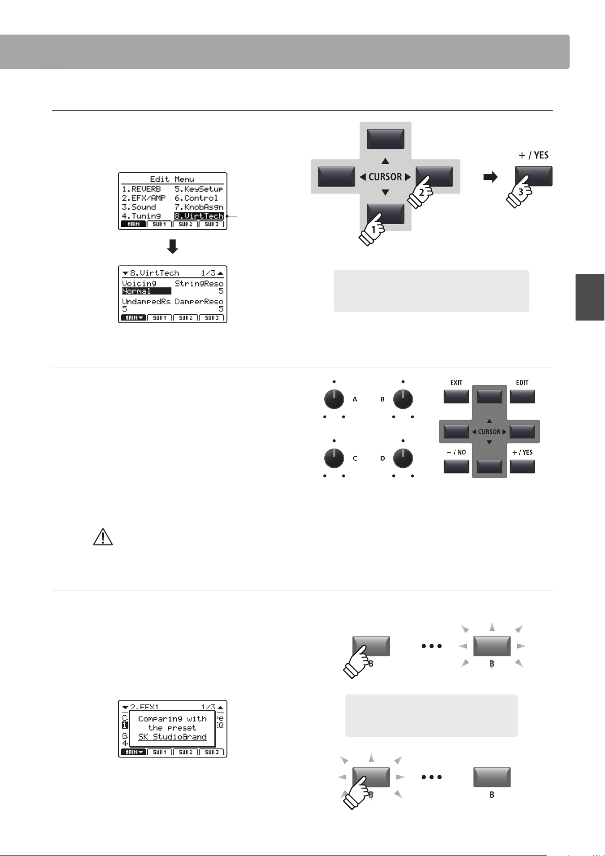
39
EDIT Menu
Selecting the parameter category
After entering the EDIT Menu:
Press the CURSOR buttons to select the desired category, then
press the +/YES button to enter the selected category.
Virtual
Technician
selected
Adjusting parameters
After selecting the parameter category:
Turn the four control knobs (A, B, C, D) to adjust the parameters
assigned to those knob.
Parameters can also be adjusted by using the CURSOR buttons
to move the selection cursor, and +/YES or –/NO buttons to
increase or decrease the value of the selected parameter.
Press the EXIT button to exit the parameter category, or return
to the Play Mode screen.
Parameter adjustments made to the selected sound will be lost upon selecting another sound.
* To store the adjusted sound, use the STORE button (page 64).
Quick Compare function
The Quick Compare function allows any sound being adjusted to be compared ‘on the y’ with the previously stored (i.e. preset) sound.
While in EDIT mode:
Press the variation button of the sound that is being adjusted.
The LED for the variation button will start to ash, and the
keyboard will play the previously stored sound.
Press the variation button again.
The LED for the variation button will stop ashing, turn ON, and
the keyboard will returning to playing the adjusted sound.
× 3
Example: To enter the Virtual Technician category, press
the CURSOR button three times and the CURSOR
button once, then press the +/YES button.
Overview of the EDIT Menu (INT mode)
Example: To compare the adjusted SK Studio
Grand sound with the previously stored version,
press the ‘B’ sound variation button.
40
EDIT Menu
EDIT Menu parameters (INT mode)
1
Reverb
1. Type
This parameter selects the reverb type.
* For more information about reverb, please refer to page 27.
* This parameter is common for all four zones.
* This parameter is not stored to SOUND but to SETUP only.
2. Pre Delay
This parameter adjusts the delay time before the start of the
reverberation.
* For more information about reverb, please refer to page 27.
* This parameter is common for all four zones.
* This parameter is not stored to SOUND but to SETUP only.
3. Time
This parameter adjusts the reverb time.
* For more information about reverb, please refer to page 27.
* This parameter is common for all four zones.
* This parameter is not stored to SOUND but to SETUP only.
4. Depth
This parameter adjusts the reverb depth.
* For more information about reverb, please refer to page 27.
2
.1 EFX
1. Category
This parameter selects the eect category.
* For more information about eects, please refer to page 28.
* The MAIN zone lists two pages for EFX1 and EFX2.
2. Type
This parameter selects the eect type.
* For more information about eects, please refer to page 28.
* The MAIN zone lists two pages for EFX1 and EFX2.
3. Parameters
These parameters change depending on the selected EFX
type, and are used to adjust the mixing amount of the eected
(wet) and bypassed (dry) sound, depth, speed, feedback, etc.
* For more information about eects, please refer to page 28.
value: 0 ~ 200 ms
value
: 0 ~ 127value: 300 ms ~ 10.0 s
6 types
23 categories main: 129 types / sub: 22 types
n
/a

41
EDIT Menu
EDIT Menu parameters (INT mode)
2
.2 Amp Simulator (MAIN zone)
1. Amp Type
This parameter selects the simulated amplier type.
* For more information about the various Amp Simulator model types,
please refer to page 30.
2. Drive
This parameter adjusts the amount of overdrive produced by
the simulated amplier.
* For more information about the Amp Simulator, please refer to page 30.
3. Level
This parameter adjusts the volume of the simulated amplier.
* For more information about the Amp Simulator, please refer to page 30.
4. Amp EQ Lo
This parameter adjusts the level of the low frequencies of the
simulated amplier.
* This parameter functions independently of the global EQ.
* For more information about the Amp Simulator, please refer to page 31.
5. Amp EQ Mid
This parameter adjusts the level of the mid frequencies of the
simulated amplier.
* This parameter functions independently of the global EQ.
* For more information about the Amp Simulator, please refer to page 31.
6. Amp EQ Hi
This parameter adjusts the level of the high frequencies of the
simulated amplier.
* For more information about the Amp Simulator, please refer to page 31.
* This parameter functions independently of the global EQ.
7. Mid Frequency
This parameter adjusts the mid frequency band of the
simulated amplier, levelled by the Amp EQ Mid parameter.
* For more information about the Amp Simulator, please refer to page 31.
* This parameter functions independently of the global EQ.
8. Mic Type
This parameter selects the type of microphone used for the
simulated amplier.
Mic Type Description
Condenser
A microphone with a very broad frequency
response that is typically found in studios.
Dynamic
A microphone with a more limited frequency
response that is typically used for live playing.
* For more information about the Amp Simulator, please refer to page 31.
9. Mic Position
This parameter selects the position of the microphone used for
the simulated amplier.
Mic Position Description
On Axis
The microphone is placed in the centre of the
speaker, producing a direct, aggressive sound with
strong high/mid range.
O Axis
The microphone is placed to the side of the speaker,
producing a smoother and more ambient sound.
* For more information about the Amp Simulator, please refer to page 31.
10. Ambience
This parameter adjusts the level (mix ratio) of an additional set
of stereo microphones, that are placed away from the simulated
amplier in order to capture the ambient sound within a room.
* For more information about the Amp Simulator, please refer to page 31.
value: 0 ~ 127
value: 0 ~ 127
5
types
value
: –10 db ~ +10 db
value: 200 Hz ~ 3150 Hzvalue: –10 db ~ +10 db
value: –10 db ~ +10 db
on axis, off axiscondenser, dynamic
value
: 0 ~ 127

42
EDIT Menu
EDIT Menu parameters (INT mode)
3
Sound
1. Master Volume
value: 0 ~ 127
This parameter adjusts the total SETUP volume, allowing the
volume of multiple SETUPs to be balanced.
* This parameter is common for all four zones.
* This parameter is not stored to SOUND but to SETUP only.
2. Panpot value: l64 ~ r63
This parameter adjusts the left/right position of the selected
sound within the stereo eld.
3. Filter Cut-o
value: –64 ~ +63
This parameter adjusts the frequency of the cut-o. Raising
the cut-o level increases the brightness of the sound, while
lowering the cut-o level results in a duller sound.
4. Filter Resonance value: –64 ~ +63
This parameter adjusts the amount of the harmonic overtone
around the cut-o frequency for the selected sound.
5. DCA Attack Time value: –64 ~ +63
This parameter adjusts the length of the attack. Higher values
increase the attack time, resulting in a longer, slower attack for
the selected sound.
6. DCA Decay Time value: –64 ~ +63
This parameter adjusts the length of the decay from peak level
to sustain level for the selected sound.
7. DCA Sustain Level value: –64 ~ +63
This parameter adjusts the volume level of the sustain heard
while the key is held for the selected sound.
8. DCA Release Time value: –64 ~ +63
This parameter adjusts the amount of time required for the
sound to fade out after the keys are released for the selected
sound.
9. DCF Attack Time value: –64 ~ +63
This parameter adjusts the length of the lter’s attack. Higher
values increase the attack time, resulting in a longer, slower
attack for the lter.
10. DCF Attack Level value: –64 ~ +63
This parameter adjusts the level of the lter’s attack.
11. DCF Decay Time value: –64 ~ +63
This parameter adjusts the length of the decay from peak level
to sustain level for the lter.
12. DCF Sustain Level value: –64 ~ +63
This parameter adjusts the level of the lter’s sustain heard
while the key is held for the selected sound.
13. DCF Release Time value: –64 ~ +63
This parameter adjusts the amount of time required for the lter
to fade out after the keys are released.
14. DCF Touch Depth value: –64 ~ +63
This parameter adjusts how much the velocity aects the lter
envelope depth.
15. DCA Touch Depth value: –64 ~ +63
This parameter adjusts how much the velocity aects the
amplitude envelope depth.
* With the exception of Volume, the Sound parameters on these pages will
not be available when tonewheel organ mode is selected.
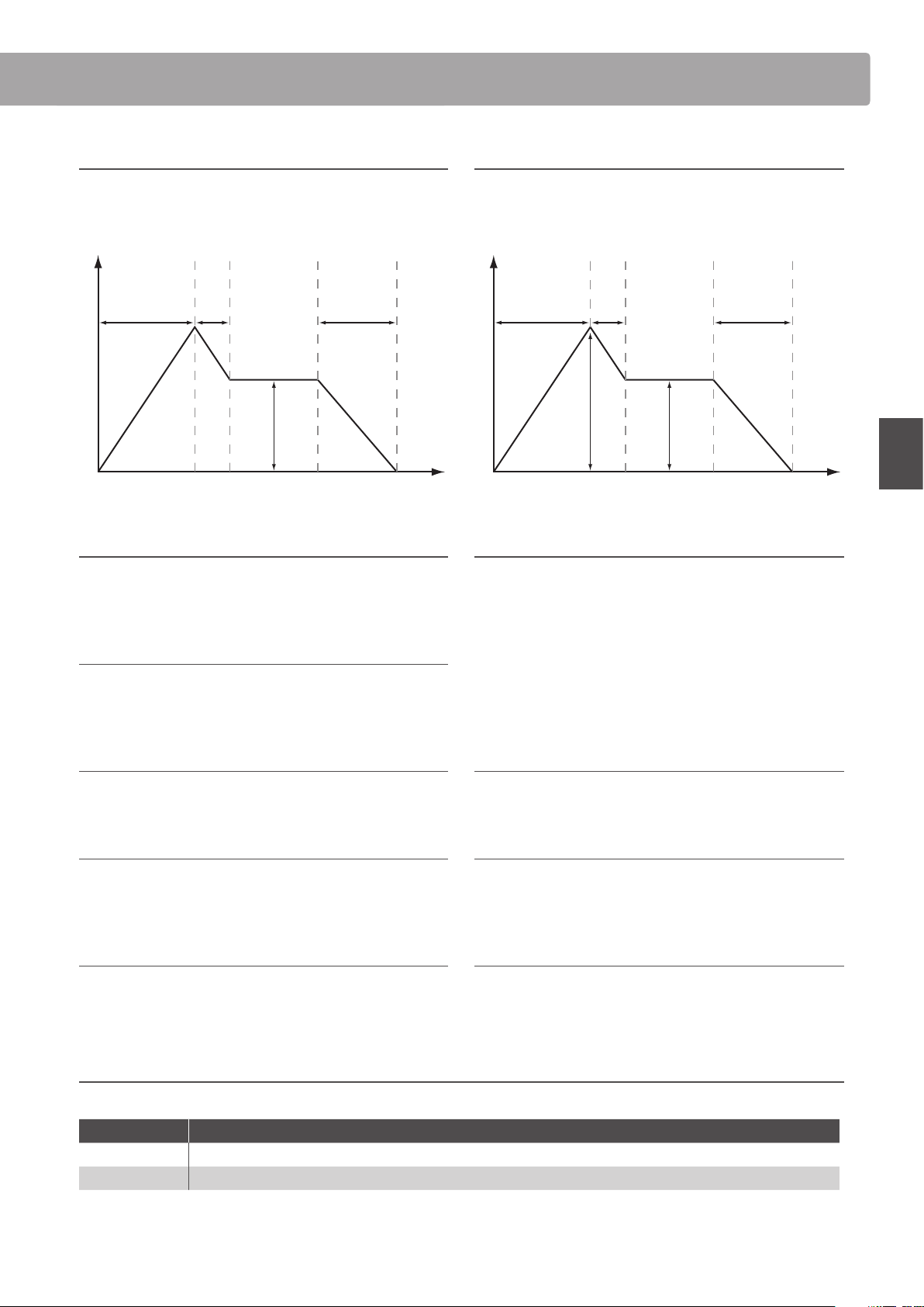
43
EDIT Menu
EDIT Menu parameters (INT mode)
16. Vibrate Depth value: –64 ~ +63
This parameter adjusts the depth of the vibration applied to the
selected sound.
17. Vibrate Rate value: –64 ~ +63
This parameter adjusts the speed of the vibration applied to the
selected sound.
18. Vibrate Delay value: –64 ~ +63
This parameter adjusts the delay time before the start of the
vibration.
19. Octave Layer Switch off, on
This parameter turns the additional Octave Layer ON or OFF.
20. Octave Layer Level value: 0 ~ 127
This parameter adjusts the volume level of the Octave Layer.
21. Octave Layer Range value: –2 ~ +2
This parameter sets the amount of octave transposition for the
Octave Layer.
22. Octave Layer Detune value: –64 ~ +63
This parameter adjusts the tuning of the Octave Layer.
23. Portamento off, on
This parameter turns portamento playing ON or OFF.
Portamento describes the eect of pitch sliding from one note to another.
24. Portamento Time value: 0 ~ 127
This parameter adjusts the time required for the portamento
(i.e. the speed of the ‘slide’ between notes).
25. Portamento Mode rate, equal
This parameter changes the portamento mode.
Portamento Mode Description
Rate The time required for the portamento will be variable. The distance between notes will aect the portamento time.
Equal The time required for the portamento will be constant. The distance between notes will not aect the portamento time.
Time
Volume
Key ON Key OFF
5
6
7
8
About DCA Parameters
The DCA (Digitally Controlled Amplier) parameters, are used to
adjust the volume level of a sound over time using an envelope.
The diagram below indicates the MP7SE’s DCA parameters.
About DCF Parameters
The DCF (Digitally Controlled Filter) parameters, are used to
adjust a low-pass lter applied to the sound over time.
The diagram below indicates the MP7SE’s DCF parameters.
Time
Frequency
Key ON Key OFF
9
11
12
13
10
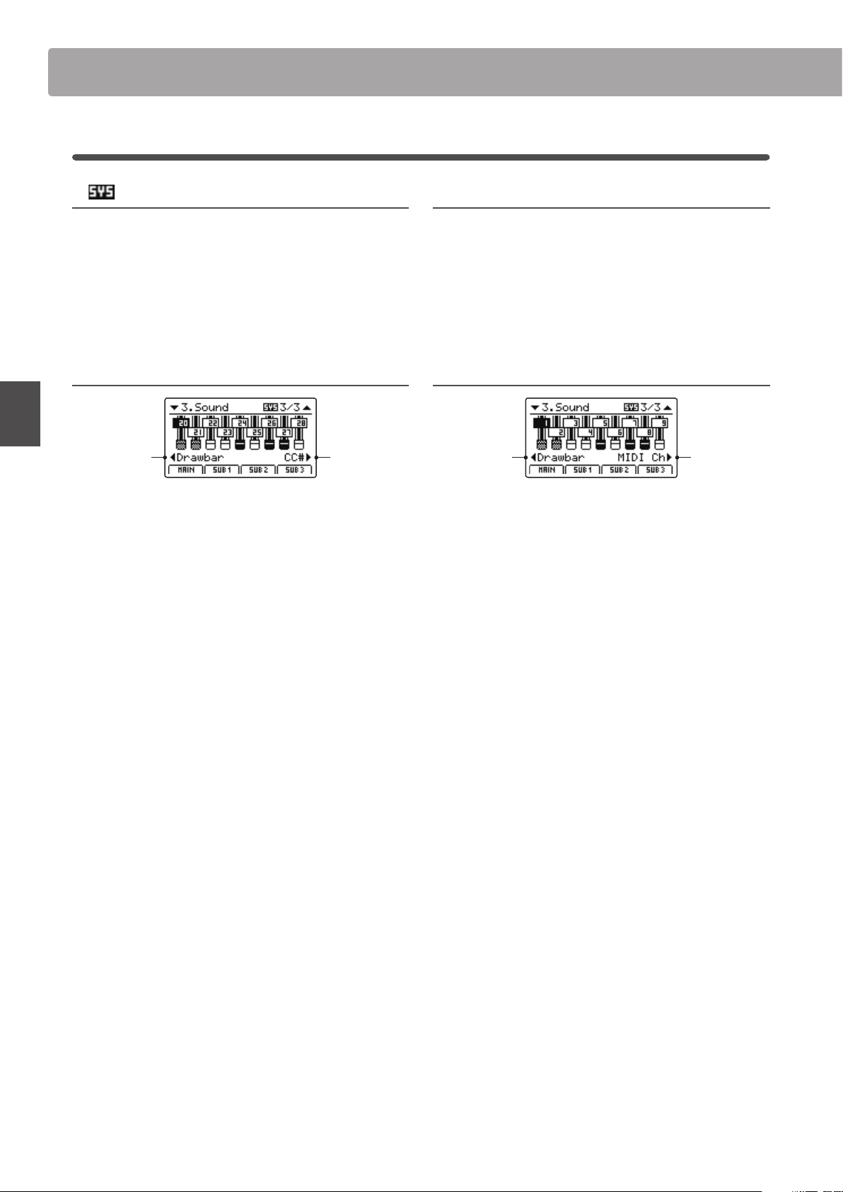
44
EDIT Menu
EDIT Menu parameters (INT mode)
3
Sound (MAIN zone, TONEWHEEL mode)
1. External Control
off, midi cc# midi cH
This parameter determines whether or not the toneweel organ
drawbars can be adjusted by external MIDI devices. When set
to CC# or MIDI Ch, an additional parameter page will appear,
allowing CC# or MIDI channels to be assigned to each drawbar.
* This is a SYSTEM parameter and therefore memorised automatically. For
more information about SYSTEM parameters, please refer to page 106.
2. MIDI CC#
value: cc#0 ~ cc#119
This parameter sets the CC# used for adjusting tonewheel organ
drawbars when MIDI Control is set to MIDI Ch.
* This is a SYSTEM parameter and therefore memorised automatically. For
more information about SYSTEM parameters, please refer to page 106.
MIDI CC# Drawbar Assign value: cc#0 ~ cc#119
Knob C:
select
drawbar
Knob D:
assign
MIDI CC#
Turn control knob C to select the drawbar, and control knob D
to assign the MIDI CC#.
MIDI Ch Drawbar Assign value: 01cH ~ 16cH
Knob C:
select
drawbar
Knob D:
assign
MIDI Ch
Turn control knob C to select the drawbar, and control knob D to
assign the MIDI channel.

45
EDIT Menu
EDIT Menu parameters (INT mode)
4
Tuning
1. Fine Tune
value: –64 ~ +63
This parameter adjusts the tuning of the selected sound for
values smaller than a semi-tone.
2. Stretch Tuning 9 types + 5 user
This parameter selects the level of stretch tuning.
The human ear typically detects high and low frequencies less
accurately than those frequencies within the middle range. The
tuning of an acoustic piano is therefore ‘stretched’ to compensate,
ensuring that the sound will be heard more naturally to the ears.
* For information about creating User Stretch Tuning, please refer to the
User Edit explanation in the SYSTEM menu chapter (page 115).
3. Temperament
7 types + 2 user
This parameter selects the tuning system of the selected sound.
* For information about creating User Temperaments, please refer to the
User Edit explanation in the SYSTEM menu chapter (page 113).
4. Key of Temperament range: c ~ b
This parameter selects the key of the selected temperament.
When using a temperament other than Equal Temperament,
use this setting to specify the key signature of the piece.
* This parameter will only aect the ‘balance’ of the tuning system, the pitch
of the keyboard will remain unchanged.
* With the exception of Fine Tune, the Tuning parameters on these pages
will not be available when tonewheel organ mode is selected.
Temperament types
Temperament type Description
Equal Temperament
(Equal)
This is the most popular tuning method that divides the scale into twelve equal semi-tones.
This produces the same chordal intervals in all twelve keys, and has the advantage of limitless
modulation of the key. However, the tonality of each key becomes less characteristic and no chord is in
pure consonance.
Pure Temperament
(Pure Maj./Pure Min.)
This temperament, which eliminates dissonances for thirds and fths is still popular for choral music
because of its perfect harmony.
When playing in a major key select ‘Pure Maj’ and when playing in a minor key select ‘Pure Min’.
Pythagorean Temperament
(Pythagorean)
This temperament, which uses mathematical ratios to eliminate dissonance for fths, is very limited for
use with chords, but it produces very characteristic melodic lines.
Meantone Temperament
(Meantone)
This temperament, which uses a mean between a major and minor whole tone to eliminate dissonance
for thirds, was devised to eliminate the lack of consonances experienced with certain fths for the
Mersenne pure temperament.
It produces chords that are more beautiful than those with the equal temperament.
Werkmeister III Temperament
(Werkmeis)
Kirnberger III Temperament
(Kirnberg)
These two temperaments are placed in between Meantone and Pythagorean. For music with few
accidentals, this temperament produces the beautiful chords of the mean tone, but as accidentals
increase, the temperament produces the characteristic melodies of the Pythagorean temperament.
They are used primarily for classical music written in the Baroque era to revive the original characteristics.
User Temperament
(Sys.User1/2)
User dened temperament created by raising or lowering the pitch for each semi-tone.
* For information about creating User Temperaments, please refer to the User Edit explanation in the SYSTEM menu chapter (page 113).
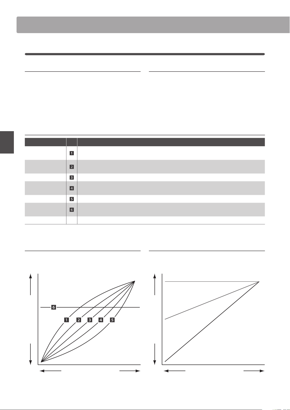
46
EDIT Menu
EDIT Menu parameters (INT mode)
5
Key Setup
1. Touch Curve
6 types + 5 user
This parameter selects the touch response curve of the keyboard
for the selected sound.
* For information about creating User Touch Curves, please refer to the User
Edit explanation in the SYSTEM menu chapter (page 112).
* This parameter will not be available when tonewheel organ mode is
selected.
2. Dynamics value: off, 1 ~ 10
This parameter adjusts the keyboard response (velocity
compression) of the selected sound independently of the touch
curve.
When the value is 10 (default), the keyboard response is normal. As the
value decreases the keyboard response gradually becomes less dynamic,
and when set to OFF becomes completely at (i.e. xed touch response).
Touch Curve types
Touch Curve No. Description
Light +
Requires less striking force to achieve a forte note.
* This touch curve is intended for players with a very delicate touch.
Light
A louder volume is produced even when playing with a soft touch.
* This touch curve is intended for players who are still developing nger strength.
Normal Reproduces the standard touch sensitivity of a typical acoustic piano.
Heavy
Requires a heavier touch to produce a loud volume.
* This touch curve is intended for players with stronger ngers.
Heavy + Requires considerably more striking force to achieve a loud volume.
O
(constant)
A constant volume is produced regardless of how hard the keys are struck.
* This touch curve is intended for playing sounds of instruments that have a xed dynamic range (e.g. harpsichord).
User* (User 1~User 5) – A custom touch curve, created to suit an individual’s personal playing style.
* For information about creating User touch curves, please refer to the User Edit explanation in the SYSTEM menu chapter (page 112).
Touch Curve graph
The illustration below provides a visual representation of the
dierent Touch Curve types.
Loud
Soft
Gentle Strong
Sound Volume
Keyboard Pressure
Dynamics graph
The illustration below provides a visual representation of the
Dynamics parameter.
Loud
Soft
Gentle Strong
Sound Volume
Keyboard Pressure
Dynamics = 10
Dynamics = 5
Dynamics = OFF

47
EDIT Menu
EDIT Menu parameters (INT mode)
3. Trigger Mode normal, fast
This parameter selects the trigger point for the keyboard.
A fast/higher trigger point may be useful when playing sounds that are
traditionally played on non-weighted keyboards such as organ or synth.
Trigger Mode Description
Normal The keyboard trigger point is normal.
Fast The keyboard trigger point is earlier than Normal.
* When either Fast mode is selected, all touch response functionality will be
disabled, and an asterisk will be shown beside the relevant Touch Curve,
Dynamics, Min.Touch, and VeloSW parameters.
* This parameter will only by visible for the MAIN zone, but when either Fast
mode is selected will aect all zones.
4. Minimum Touch value: 1 ~ 20
This parameter adjusts the minimum key velocity required to
produce a sound.
5. Octave Shift value: –3 ~ +3 octaves
This parameter adjusts the amount of octave transposition for
the selected sound.
* This parameter is not stored to SOUND but to SETUP only.
6. Zone Transpose value: –12 ~ +12
This parameter adjusts the amount of transposition for the
selected zone.
* This parameter is not stored to SOUND but to SETUP only.
7. Key Scaling Damping on, off
This parameter determines whether or not damping (velocity
reduction) should be applied to a sound over a specic range.
This parameter may be useful when layering a piano sound with a strings
sound, in order to reduce the level of the strings in the higher key range.
8. Key Scaling Key range: a0 ~ c8
This parameter denes the point on the keyboard from which
Key Scaling Damping should be applied, up to the highest key.
9. Key Range Zone Lo range: a0 ~ c8
This parameter denes the bottom key of the selected zone.
* For more information about adjusting the zone key range, please refer to
page 24.
* This parameter is not stored to SOUND but to SETUP only.
10. Key Range Zone Hi range: a0 ~ c8
This parameter denes the top key of the selected zone.
* For more information about adjusting the zone key range, please refer to
page 24.
* This parameter is not stored to SOUND but to SETUP only.
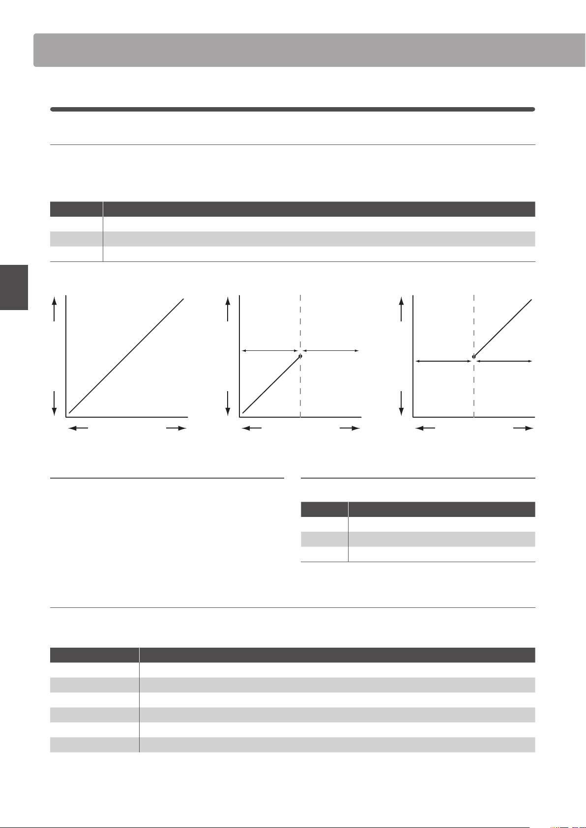
48
EDIT Menu
EDIT Menu parameters (INT mode)
11./12. Velocity Switch / Velocity Switch Value mode: off, soft, loud / value: 0 ~ 127
These parameters enable velocity switching, and set the velocity switch type and value.
Velocity Switching is useful when combining multiple zones, allowing dierent sounds to be played depending on the velocity of the key strike.
* This parameter is not stored to SOUND but to SETUP only.
Switch Mode Description
O The selected sound will play normally (i.e. no velocity switching).
Soft The selected sound will play only when the velocity is lower than the dened velocity switch value.
Loud The selected sound will play only when the velocity is higher than the dened velocity switch value.
Sound Volume
Velocity Switch O
Keyboard Velocity
Sound Volume
Velocity Switch Soft
Keyboard Velocity
Velocity Switch value
Non-sound rangeSound range
Sound Volume
Velocity Switch Loud
Keyboard Velocity
Velocity Switch value
Sound rangeNon-sound range
13. Solo on, off
This parameter determines whether or not playing will be
restricted to single notes, even when more than one note is
played simultaneously.
This parameters can be used to eectively simulate the performance
characteristics of a monophonic synthesizer.
14. Solo Mode last, HigH, low
This parameter selects the solo mode for the selected zone.
Solo Mode Description
Last Play the last note of a group of notes.
High Play the highest note of a group of notes.
Low Play the lowest note of a group of notes.
15. Key Volume 5 types + 5 user
This parameter selects the Key Volume setting for the selected sound section, if desired.
* For information about creating User Key Volumes, please refer to the User Edit explanation in the SYSTEM menu chapter (page 114).
Key Volume Description
Normal
(default) An evenly balanced volume throughout the keyboard.
High Damping Gradually reduces the volume of the keyboard towards the treble region.
Low Damping Gradually reduces the volume of the keyboard towards the bass region.
High & Low Damping Gradually reduces the volume of the keyboard in both the treble and bass regions.
Center Damping Gradually reduces the volume of the keyboard in the central region.
User A custom keyboard volume, allowing the volume of each key to be individually adjusted.
5
Key Setup (cont.)
49
EDIT Menu
EDIT Menu parameters (INT mode)
6
Controllers
1. Damper Pedal
on, off
This parameter determines whether or not the included F-10H
damper pedal is active for the selected sound.
* For more information about connecting pedals, please refer to page 17.
2. Damper Pedal Assign
28 functions (main)
18
functions (sub)
This parameter selects the function assigned to the included
F-10H damper pedal.
* This parameter is common for all four zones.
3. Damper Pedal Mode
normal, Hold
This parameter determines whether or not the damper pedal
should sustain sounds indenitely without decay.
4. Pitch Bend on, off
This parameter determines whether or not the pitch bend
wheel is active for the selected sound.
5. Pitch Bend Range value: 0 ~ 7
This parameter sets the range of the pitch bend wheel in semi-
tone steps.
* The range diers for INT mode (0 ~7) and EXT mode (0~12).
6. Soft Pedal Depth value: 1 ~ 10
This parameter adjusts the eectiveness (i.e. depth/strength) of
the soft pedal.
7. Modulation Wheel on, reverse, off
This parameter determines whether or not the modulation
wheel is active for the selected sound.
When set to ‘Reverse’, the wheel’s output values will be inverted.
8. Modulation Wheel Assign
28 functions (main)
18
functions (sub)
This parameter selects the function assigned to the MP7SE’s
modulation wheel.
9. Modulation Depth Range value: 0 ~ 127
This parameter sets the range of the pitch modulation function
in steps of 600/127 cents.
10. SW1 Button on, off
This parameter determines whether or not the SW1 button is
active for the selected sound.
11. SW1 Button Assign 10 functions
This parameter selects the function assigned to the SW1 button.
* This parameter is common for all four zones.
12. SW2 Button on, off
This parameter determines whether or not the SW2 button is
active for the selected sound.
13. SW2 Button Assign 10 functions
This parameter selects the function assigned to the SW2 button.
* This parameter is common for all four zones.
50
EDIT Menu
EDIT Menu parameters (INT mode)
14. Footswitch Pedal on, off
This parameter determines whether or not the footswitch pedal
(if connected) is active for the selected sound.
* For more information about connecting pedals, please refer to page 18.
15. Footswitch Pedal Assign
28 functions (main)
18
functions (sub)
This parameter selects the function assigned to the footswitch
pedal (if connected).
* This parameter is common for all four zones.
16. Expression Pedal
on, reverse, off
This parameter determines whether or not the expression pedal
(if connected) is active for the selected sound.
When set to ‘Reverse’, the pedal’s output values will be inverted.
* For more information about connecting pedals, please refer to page 17.
17. Expression Pedal Assign
28 functions (main)
18
functions (sub)
This parameter selects the function assigned to the expression
pedal (if connected).
* This parameter is common for all four zones.
18. Right Pedal on, off
This parameter determines whether or not the right pedal of
the optional GFP-3 pedal unit is active for the selected sound.
* For more information about connecting pedals, please refer to page 17.
19. Right Pedal Assign
28 functions (main)
18
functions (sub)
This parameter selects the function assigned to the right pedal
of the optional GFP-3 pedal unit.
* This parameter is common for all four zones.
20. Center Pedal on, off
This parameter determines whether or not the centre pedal of
the optional GFP-3 pedal unit is active for the selected sound.
* For more information about connecting pedals, please refer to page 17.
21. Center Pedal Assign
28 functions (main)
18
functions (sub)
This parameter selects the function assigned to the centre pedal
of the optional GFP-3 pedal unit.
* This parameter is common for all four zones.
22. Left Pedal on, off
This parameter determines whether or not an ordinary foot
switch pedal or the left pedal of the optional GFP-3 pedal unit is
active for the selected sound.
* For more information about connecting pedals, please refer to page 17.
23. Left Pedal Assign
28 functions (main)
18
functions (sub)
This parameter selects the function assigned to an ordinary foot
switch pedal or the left pedal of the optional GFP-3 pedal unit.
* This parameter is common for all four zones.
Assignable pedal/mod. wheel functions
Function
Modulation
Panpot
Expression
Damper
Sostenuto
Soft
Resonance
Cut-o
EFX1 Parameter 1 ~ 10, EFX2 Parameter 1 ~ 10
(main)
EFX Parameter 1 ~ 10 (sub)
Assignable SW1/SW2 button functions
Function
Octave Layer
Rotary Slow/Fast
Solo
Portamento
Pitch Bend Lock
Modulation Wheel Lock
Center Pedal Lock
Left Pedal Lock
Expression Pedal Lock
Tonewheel Control
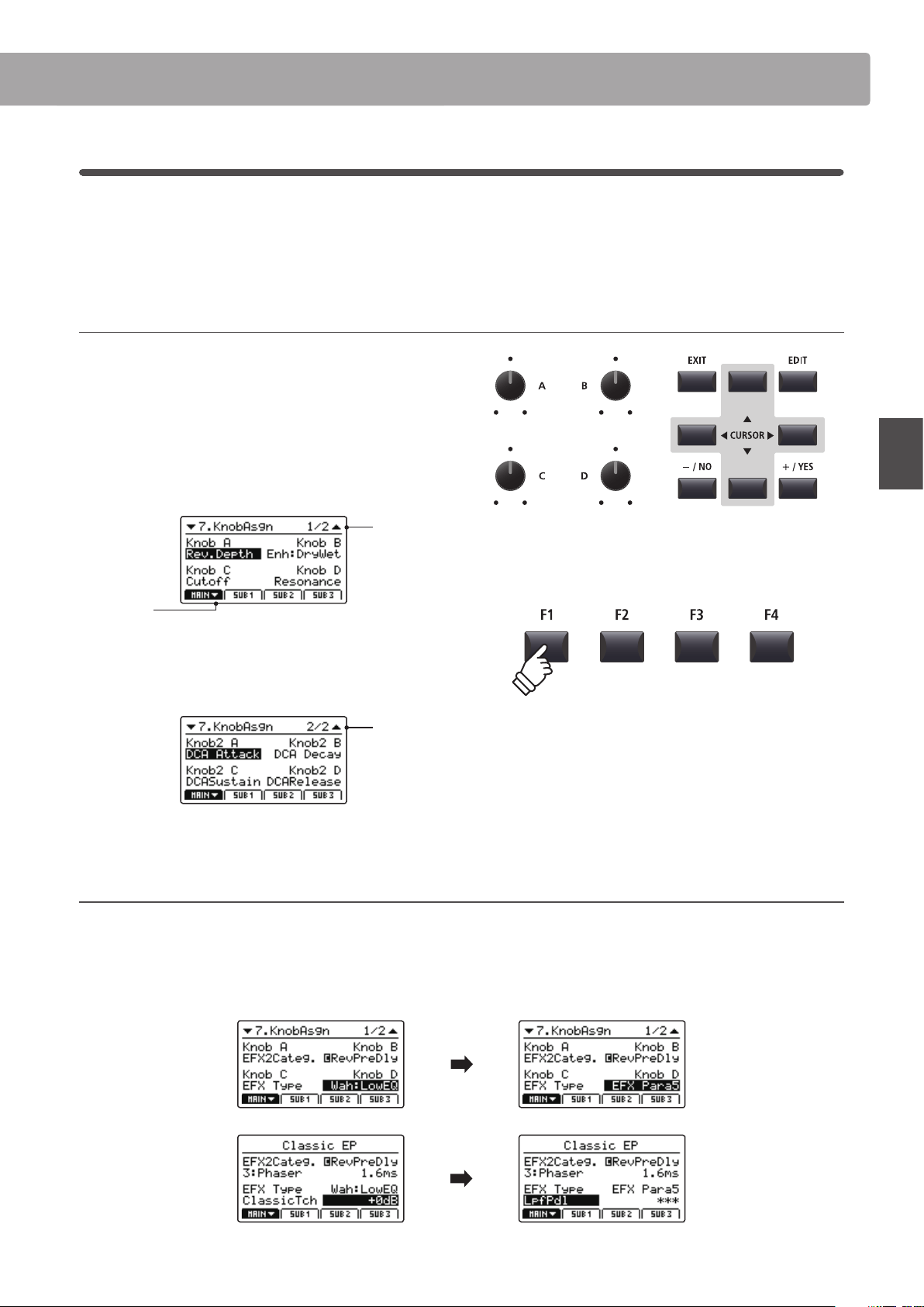
51
EDIT Menu
EDIT Menu parameters (INT mode)
7
Knob Assign
The Knob Assign screen is used to assign EDIT menu parameters to the four main control knobs A, B, C, and D
for direct, real-time adjustment in Play Mode. Two groups of knob parameters (primary and secondary) can be
assigned to each of the four zones, providing extensive control over the selected sounds.
Assigning parameters to each knob
Enter the Knob Assign screen for the desired section.
Turn the four control knobs (A, B, C, D) to specify which parameter
should be assigned to each control knob in Play Mode.
Parameters can also be assigned by using the CURSOR buttons
to move the selection cursor, and +/YES or –/NO buttons to
cycle through the available parameters.
Page 1/2
arrow:
Next page
Press the F1~F4 function buttons (depending on the selected
zone) or CURSOR buttons to show the secondary group of
knob parameters in the LCD display.
Page 2/2
About EFX parameter placeholder names (EFX Para1~10)
Some EFX oer a wide range of available parameters, while others are less exible and feature fewer adjustable parameters. When assigning
EFX parameters to the four control knobs, the names of the available parameters for the selected EFX (e.g. Wah:LowEQ) will be shown.
If the selected EFX features a smaller number of available parameters, a placeholder name (e.g. ‘EFX Para 5’) will be substituted in the Knob
Assign menu, and the knob will become inactive in the main play screen.
* Assignable parameters dier slightly for each sound section. For a full list
of assignable parameters, please refer to the page 150.
* For more information about adjusting parameters in Play Mode, please
refer to page 26.
Knob Assign screen
ClassichTch Wah selected,
LowEQ parameter assigned
to control knob D.
Play screen
ClassichTch Wah selected,
control knob D shows
Wah:LowEQ parameter.
Knob Assign screen
LpfPdl Wah selected, control
knob D changes to EFX
Para5 parameter
(i.e. inactive).
Play screen
LpfPdl Wah selected, control
knob D changes to EFX
Para5 (i.e. inactive).

52
EDIT Menu
EDIT Menu parameters (INT mode)
8
Virtual Technician (PIANO sounds)
1. Voicing
6 types + 5 user
This parameter attempts to recreate the technique of adjusting the action, hammers and strings of an acoustic piano, allowing the
tonal character and dynamics of the MP7SE’s piano sounds to be dramatically altered.
Voicing types
Voicing Type Description
Normal The normal tonal character of an acoustic piano throughout the entire dynamic range.
Mellow 1 A softer, more mellow tonal character throughout the entire dynamic range.
Mellow 2 An even soften tonal character than Mellow 1.
Dynamic A tonal character that changes dramatically from mellow to bright, depending on the strength of key strike.
Bright 1 A bright tonal character throughout the entire dynamic range.
Bright 2 An even brighter tonal character than Bright 1.
User A custom tonal character, allowing each key to be individually voiced.
* For information about creating User Voicing, please refer to the User Edit explanation in the SYSTEM menu chapter (page 116).
2. String Resonance value: off, 1 ~ 10
This parameter adjusts the volume of the string resonance.
String Resonance refers to a phenomenon that exists in acoustic pianos
whereby the strings of held notes resonate ‘sympathetically’ with other
notes of the same harmonic series.
3. Undamped Resonance value: off, 1 ~ 10
This parameter adjusts the volume of the undamped resonance.
The dampers of an acoustic piano span almost the full width of the
keyboard. However, the topmost 18 keys (approximately 1.5 octaves) do
not incorporate dampers, as the shorter strings for these treble notes decay
quickly and therefore do not need to be dampened. As a result, the strings of
these ‘undamped’ treble notes are free to vibrate in sympathetic resonance
with those of lower keys – independently of the damper pedal position –
helping to enrich the sound with additional harmonics and tonal colour.
4. Damper Resonance value: off, 1 ~ 10
This parameter adjusts the volume of the damper resonance.
Depressing the damper pedal of an acoustic piano raises all dampers,
allowing the strings to vibrate freely. When a note or chord is played on the
piano with the sustain pedal depressed, not only will the strings of the notes
played vibrate, but also the strings of other notes, vibrating in sympathetic
resonance.
5. Key-o Eect value: off, 1 ~ 10
This parameter adjusts the volume of the key-o eect.
When playing an acoustic piano – particularly in the bass region of the
keyboard – if a key is played with force and released quickly, it is often
possible to hear the faint sound of the damper touching the strings
immediately before the vibrations are stopped.
6. Damper Noise value: off, 1 ~ 10
This parameter adjusts the volume of the damper noise.
When the damper pedal is depressed and released, it is often possible to
hear the sound of the damper head touching and releasing the strings.
7. Hammer Delay value: off, 1 ~ 10
This parameter adjusts the delay of the hammer striking the
string when playing with pianissimo.

53
EDIT Menu
EDIT Menu parameters (INT mode)
8. Fall-back Noise value: off, 1 ~ 10
This parameter adjusts the volume of the noise heard when the
keyboard action ‘falls back’ after a key is released.
9. Topboard close, open1, open2, open3
This parameter changes the position of the piano’s topboard.
When playing an acoustic grand piano, the position of the instrument’s
topboard (lid) aects both the volume and ‘openness’ of the tone produced.
A fully open topboard allows sound waves to reect o the polished lid
surface and project into the room, while a closed lid has the opposite eect,
resulting in a darker, more opaque tone.
10. Stereo Width
value: 0 ~ 127
This parameter adjusts the width of the stereo sound.
Virtual Technician (E.PIANO, HARPSICHORD, BASS sounds)
1. Key-o Noise value: off, 1 ~ 127
When an E.PIANO category sound is selected, this parameter
adjusts the volume of the noise heard when the keys of an
electromechanical instrument are released.
When a harpsichord or bass sound is selected this parameter
adjusts the volume of the release noise for harpsichord and
bass sounds.
2. Key-o Delay value: 0 ~ 127
This parameter adjusts the delay time before the Key-o Noise
is heard.
Virtual Technician (DRAWBAR sounds)
1. Key Click Level value: off, 1 ~ 127
This parameter adjusts the volume of the key click sound when
playing drawbar organ sounds.
2. Wheel Noise Level value: 0 ~ 127
This parameter adjusts the volume of the ambient noise
produced by the organ’s spinning tonewheels.
Increase the value of this parameter to give the tonewheel organ a more
vintage character.
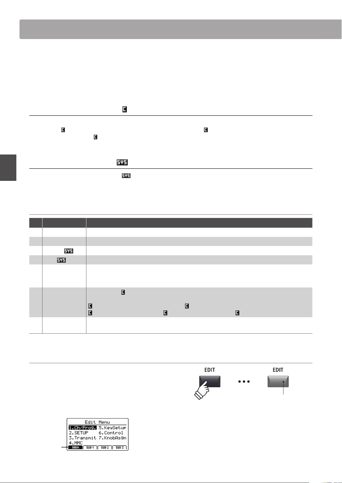
54
EDIT Menu
Overview of the EDIT Menu (EXT mode)
The EDIT menu can also be used to adjust parameters for zones in EXT mode. As with the INT mode EDIT menus, the
parameters are grouped by category, providing direct control over any connected MIDI devices.
As with zones set to INT mode, this collection of parameters, together with other adjustable settings, can be stored
as a SETUP memory (page 65). The MP7SE provides 256 user programmable SETUP memories.
About Common parameters ( icon)
Unless stated, parameter settings for the MAIN, SUB1, SUB2, and SUB3 zones are independent for each zone. However, parameters
marked with a
icon are common for all four zones. For example, changing the Right Pedal Assign parameter for the MAIN zone
will automatically change the
Right Pedal Assign parameter for the SUB1, SUB2, and SUB3 zones.
About System parameters ( icon)
EXT mode zone parameters marked with a icon are SYSTEM parameters and memorised automatically, without the need to use
the STORE function.
EXT mode zone parameters
No. Category Parameters
1 Channel/Program MIDI Transmitting Channel, Program, Bank MSB, Bank LSB
2 SETUP Send Program, Send Bank, Send Volume, Send Knobs
3 Transmit
Transmit System Exclusive, Transmit Recorder, Fader Assign
4 MMC
Transmit MMC, MMC Device ID, MMC Commands
5 Key Setup
Touch Curve, Dynamics, Trigger Mode, Octave Shift, Zone Transpose, Key Scaling Damping,
Key Scaling Key, Key Range Zone Lo, Key Range Zone Hi, Velocity Switch, Velocity Switch Value, Solo,
Solo Mode, Transmit Keyboard
6
Controllers
Damper Pedal,
Damper Pedal Assign, Half Pedal Values, Pitch Bend, Pitch Bend Range,
Modulation Wheel, Modulation Wheel Assign, Modulation Wheel Range, Footswitch Pedal,
Footswitch Pedal Assign, Expression Pedal, Expression Pedal Assign, Right Pedal,
Right Pedal Assign, Center Pedal, Center Pedal Assign, Left Pedal, Left Pedal Assign
7 Knob Assign
Knob A Assign, Knob B Assign, Knob C Assign, Knob D Assign,
Knob2 A Assign, Knob2 B Assign, Knob2 C Assign, Knob2 D Assign
Entering the EDIT Menu
When the zone is in EXT mode:
Press the EDIT button.
The LED indicator for the EDIT button will turn ON, and the Edit
Menu for the selected zone will be shown in the LCD display.
MAIN
zone
selected
LED indicator ON:
EDIT mode is turned ON
* To change the selected zone, press the F1~F4 buttons.
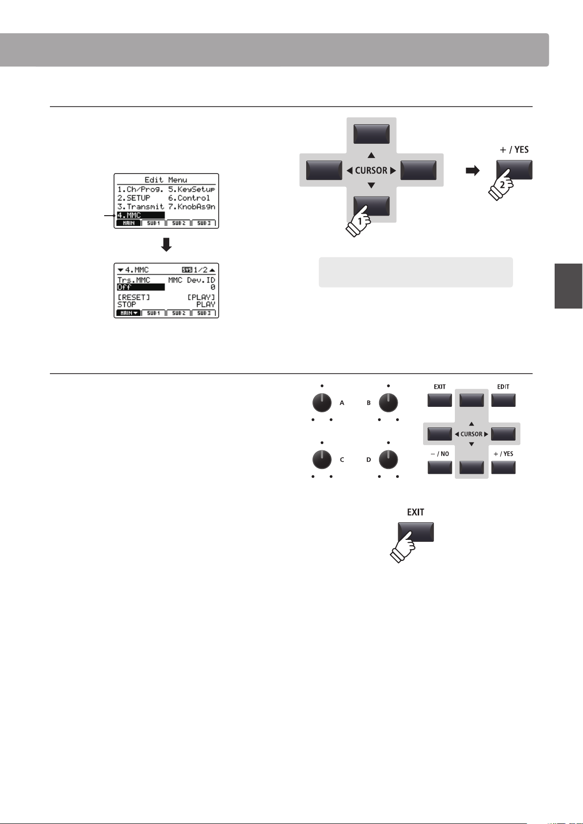
55
EDIT Menu
Overview of the EDIT Menu (EXT mode)
Selecting the parameter category
After entering the EDIT Menu:
Press the CURSOR buttons to select the desired category, then
press the +/YES button to enter the selected category.
MMC
selected
Adjusting parameters
After selecting the parameter category:
Turn the four control knobs (A, B, C, D) to adjust the parameters
assigned to those knob.
Parameters can also be adjusted by using the CURSOR buttons
to move the selection cursor, and +/YES or –/NO buttons to
increase or decrease the value of the selected parameter.
Press the EXIT button to exit the parameter category, or return
to the Play Mode screen.
× 3
Example: To enter the MMC category, press the CURSOR
button three times, then press the +/YES button.
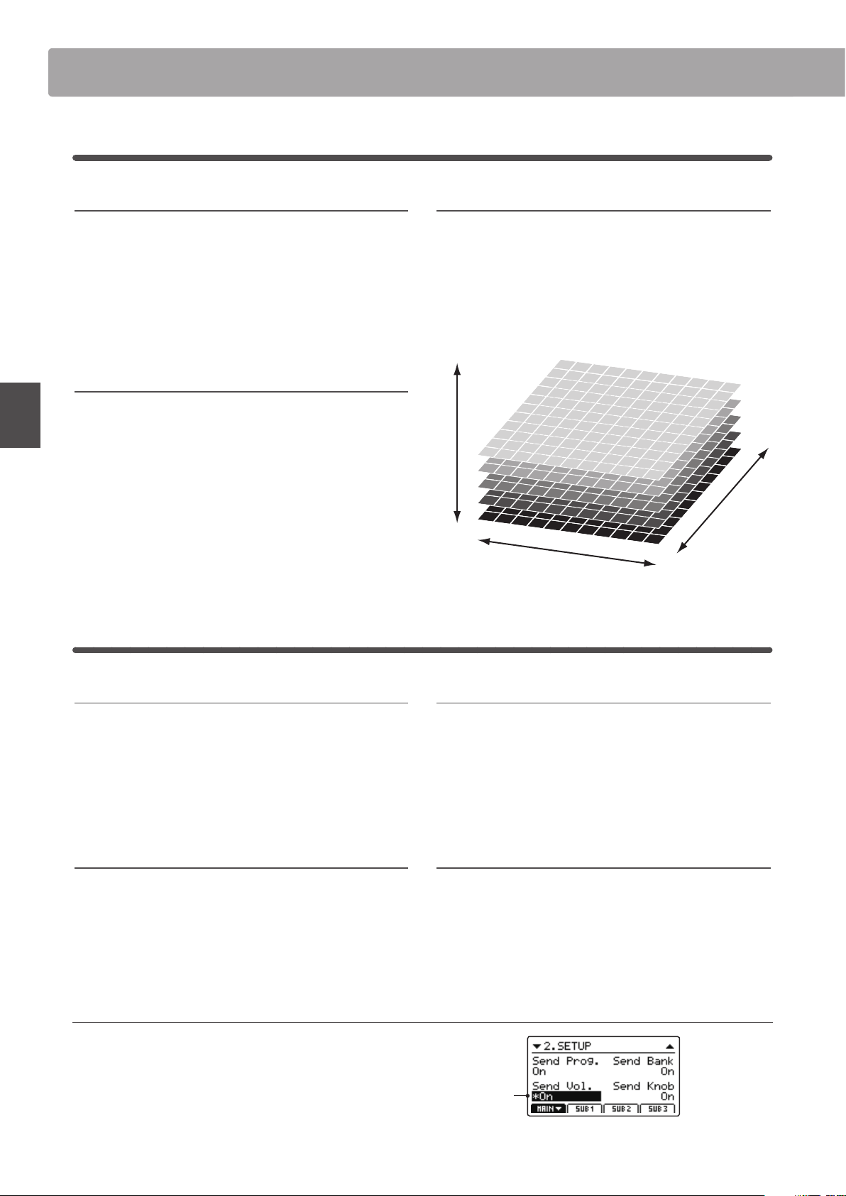
56
EDIT Menu
EDIT Menu parameters (EXT mode)
1
Channel/Program
1. MIDI Transmitting Channel
This parameter determines which MIDI channel will be used to
transmit event information for the selected zone.
* By default, SUB2 and SUB3 zones are assigned MIDI channels 01 and 02.
MAIN and SUB1 zones are assigned MIDI channels 03 and 04.
* The specied MIDI transmit channel should match the MIDI Receive
channel of the connected MIDI device.
2. Program
This parameter determines which Program Change Number
will be transmitted when a SETUP is recalled. For example,
the desired Program number of a sound on the external MIDI
device.
3/4. Bank MSB/Bank LSB
This parameter determines which MSB and LSB number will
be transmitted when a SETUP is recalled. The MIDI standard
allocates 128 storage spaces, however this number can be
expanded using an MSB and an LSB.
The diagram to the right illustrates how the Program Number,
MSB Bank, and LSB Bank are organised.
* Please refer to the owner’s manual of the connected MIDI device for
further information.
2
SETUP
1. Send Program
This parameter determines whether or not a Program Change
Number will be transmitted when a SETUP is recalled.
To change sounds on external MIDI devices when recalling a SETUP, set
this parameter to ON.
2. Send Bank
This parameter determines whether or not Program Bank
Numbers (MSB, LSB) will be transmitted when a SETUP is
recalled.
If the external MIDI device requires a Bank Select message, set this
parameter to ON.
3. Send Volume
This parameter determines whether or not an initial MIDI
Volume message will be transmitted when a SETUP is recalled.
* Adjusting the volume of a zone by turning the control knobs will still
transmit values even if this parameter is set to OFF.
4. Send Knobs
This parameter determines whether or not control knob
settings will be transmitted (ON) or not (OFF) when a SETUP
is recalled.
* Turning the control knobs will still transmit values even if this parameter
is set to OFF.
SETUP parameters in the SYSTEM menu
The above Send parameters can be overridden by the SETUP
Program, SETUP Bank, SETUP Volume, SETUP Knobs parameters
in the MIDI category of the SYSTEM menu (page 110).
When these SETUP parameters are set to OFF, an asterisk will be
shown beside the relevant Send parameter to indicate that the
EDIT menu setting is being overridden.
value: 01cH ~ 16cH
on, off
on, off
on, off
on, off
value
: 1 ~ 128
value: 0 ~ 127
Program Number
MSB Bank
LSB Bank
Asterisk:
Parameter is
overridden by
SETUP menu
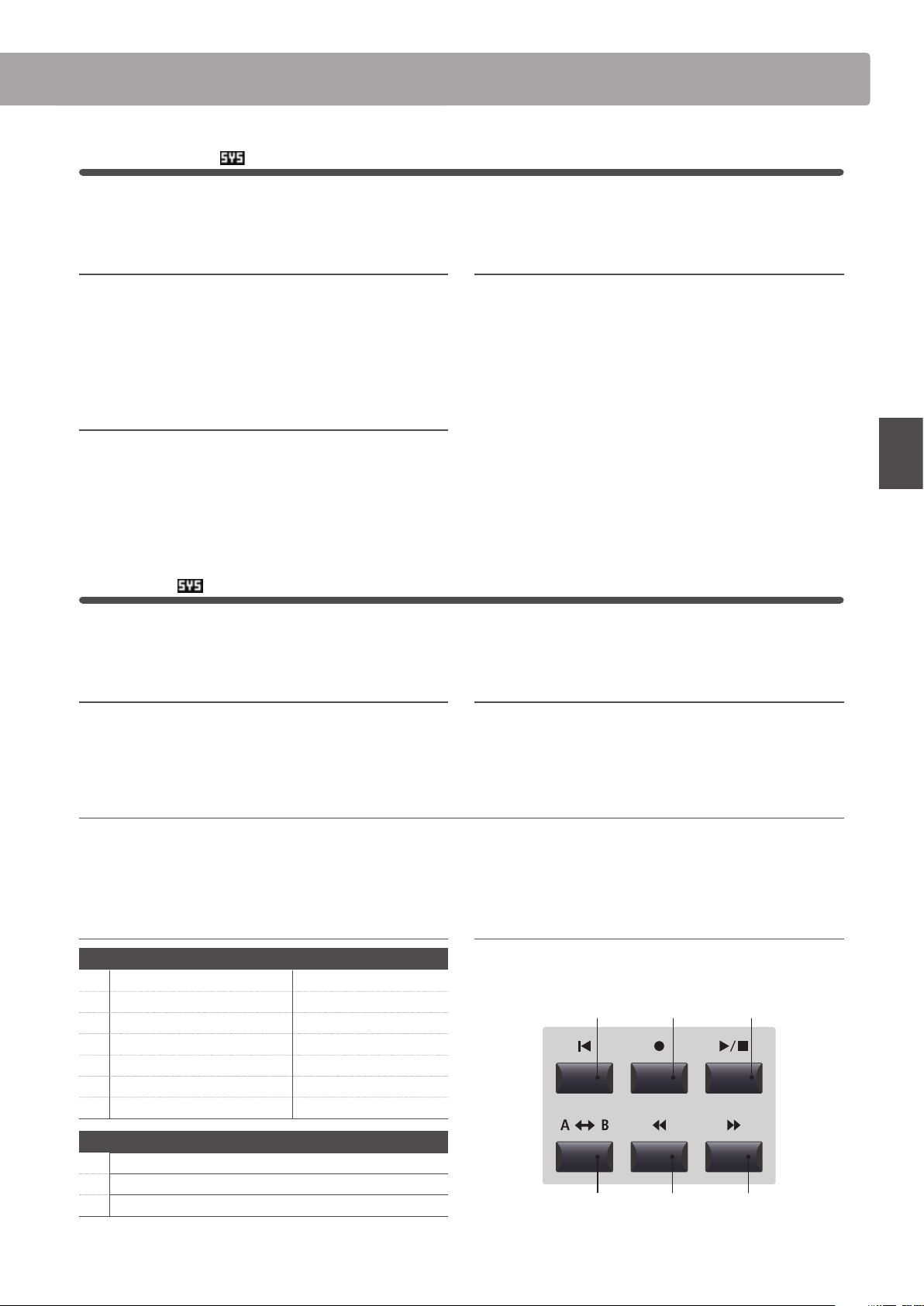
57
EDIT Menu
EDIT Menu parameters (EXT mode)
3
Transmit
The Transmit category parameters are all SYSTEM parameters. These parameters are memorised automatically and
therefore do not need to be stored to each SETUP.
1. Transmit System Exclusive on, off
This parameter determines whether or not System Exclusive
(SYSEX) data will be transmitted to an external MIDI device.
* For more information about System Exclusive data transmitted by the
MP7SE, please refer to page 141.
2. Transmit Recorder on, off
This parameter determines whether or not data will be
transmitted to an external MIDI device when playing internal
recorder songs.
3. Fader Assign
cc#0 ~ cc#119, aftertoucH
This parameter selects the function assigned to the zone’s fader.
* By default, the fader for an EXT mode zone is set to CC#07 (Volume).
4
MMC
The MMC category parameters are all SYSTEM parameters. These parameters are memorised automatically and
therefore do not need to be stored to each SETUP.
1. Transmit MMC on, off
This parameter determines whether or not the MP7SE’s recorder
control buttons will transmit MMC (MIDI Machine Control) data.
2. MMC Dev. ID value: 0 ~ 127
This parameter determines the device ID of the MMC (MIDI
Machine Control).
3. MMC Commands 13 mmc commands, 3 realtime commands
These parameters allow MMC or Realtime commands to be assigned to the MP7SE’s six recorder control buttons.
* By default, the main MMC commands should be correctly mapped to the MP7SE’s recorder control buttons.
Assignable recorder control commands
MMC Commands
01 STOP 08 RECORD PAUSE
02 PLAY 09 PAUSE
03 DEFERRED PLAY 0A EJECT
04 FAST FORWARD 0B CHASE
05 REWIND 0C COMMAND ERROR RESET
06 RECORD STROBE 0D MMC RESET
07 RECORD EXIT
Realtime Commands
FA Realtime START
FB Realtime CONTINUE
FC Realtime STOP
Recorder control buttons
The illustration below indicates the names of the six recorder
control buttons:
A
B
RESET PLAYREC
REW FF
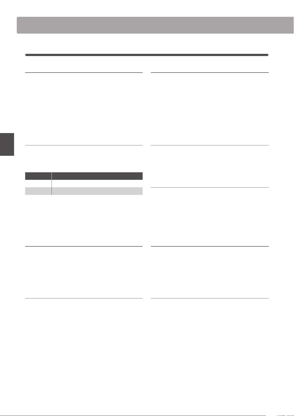
58
EDIT Menu
EDIT Menu parameters (EXT mode)
5
Key Setup
1. Touch Curve
6 types + 5 user
This parameter selects the touch response curve of the keyboard
for the selected zone.
* For more information about touch curve types, please refer to page 46.
* For information about creating User Touch Curves, please refer to the User
Edit explanation in the SYSTEM menu chapter (page 112).
* This parameter will not be available when tonewheel organ mode is
selected.
2. Dynamics value: off, 1 ~ 10
This parameter adjusts the keyboard response (velocity
compression) of the selected zone independently of the touch
curve.
When the value is 10 (default), the keyboard response is normal. As the
value decreases the keyboard response gradually becomes less dynamic,
and when set to OFF becomes completely at (i.e. xed touch response).
* For more information about dynamics, please refer to page 46.
3. Trigger Mode
normal, fast
This parameter selects the trigger point for the keyboard.
A fast/higher trigger point may be useful when playing sounds that are
traditionally played on non-weighted keyboards such as organ or synth.
Trigger Mode Description
Normal The keyboard trigger point is normal.
Fast The keyboard trigger point is earlier than normal.
* When either Fast mode is selected, all touch response functionality will be
disabled, and an asterisk will be shown beside the relevant Touch Curve,
Dynamics, Min.Touch, and VeloSW parameters.
* This parameter will only by visible for the MAIN zone, but when either Fast
mode is selected will aect all zones.
4. Octave Shift value: –3 ~ +3 octaves
This parameter adjusts the amount of octave transposition for
the selected zone.
5. Zone Transpose value: –12 ~ +12
This parameter adjusts the amount of transposition for the
selected zone.
6. Key Scaling Damping on, off
This parameter determines whether or not damping (velocity
reduction) should be applied to a zone over a specic range.
This parameter may be useful when layering a piano sound with a strings
sound, in order to reduce the level of the strings in the higher key range.
7. Key Scaling Key range: a0 ~ c8
This parameter denes the point on the keyboard from which
Key Scaling Damping should be applied, up to the highest key.
8. Key Range Zone Lo range: a0 ~ c8
This parameter denes the bottom key of the selected zone.
* For more information about adjusting the zone key range, please refer to
page 24.
9. Key Range Zone Hi range: a0 ~ c8
This parameter denes the top key of the selected zone.
* For more information about adjusting the zone key range, please refer to
page 24.

59
EDIT Menu
EDIT Menu parameters (EXT mode)
10./11. Velocity Switch / Velocity Switch Value mode: off, soft, loud / value: 0 ~ 127
These parameters enable velocity switching, and set the velocity switch type and value.
Velocity Switching is useful when combining multiple zones, allowing dierent sounds to be played depending on the velocity of the key strike.
Switch Mode Description
O The selected sound will play normally (i.e. no velocity switching).
Soft The selected sound will play only when the velocity is lower than the dened velocity switch value.
Loud The selected sound will play only when the velocity is higher than the dened velocity switch value.
* For more information about velocity switching, please refer to page 48.
12. Solo on, off
This parameter determines whether or not playing will be
restricted to single notes, even when more than one note is
played simultaneously.
This parameters can be used to eectively simulate the performance
characteristics of a monophonic synthesizer.
13. Solo Mode last, HigH, low
This parameter selects the solo mode for the selected zone.
Solo Mode Description
Last Play the last note of a group of notes.
High Play the highest note of a group of notes.
Low Play the lowest note of a group of notes.
14. Transmit Keyboard on, off
This parameter determines whether or not keyboard Key ON/
Key OFF event data will be transmitted to an external MIDI
device.
60
EDIT Menu
EDIT Menu parameters (EXT mode)
6
Controllers
1. Damper Pedal
on, off
This parameter determines whether or not the included F-10H
damper pedal is active for the selected zone.
* For more information about connecting pedals, please refer to page 17.
2. Damper Pedal Assign cc#0 ~ cc#119, aftertoucH
This parameter selects the function assigned to the included
F-10H damper pedal.
* This parameter is common for all four zones.
3. Half Pedal Values
normal, HigH, low, mid HigH, mid low
This parameter changes the half pedal ranges sent by the included F-10H damper pedal for the selected zone.
This parameter is useful when using the MP7SE to control external tone generators (e.g. software pianos) that respond to damper pedal behaviour dierently.
Half Pedal Value Value Range Description
Normal
(default) 0 ~ 127 The damper pedal sends a full range of evenly distributed values.
High 0, 64 ~ 127 The damper pedal sends a full range of evenly distributed values after the half-pedal point is reached.
Low 0 ~ 63, 127 The damper pedal sends a full range of evenly distributed values before the half-pedal point is reached.
Mid High 0, 50 ~ 100, 127 The damper pedal sends a full range of evenly distributed values between 50 and 100.
Mid Low 0, 25 ~ 75, 127 The damper pedal sends a full range of evenly distributed values between 25 and 75.
4. Pitch Bend on, off
This parameter determines whether or not the pitch bend
wheel is active for the selected zone.
5. Pitch Bend Range value: 0 ~ 12
This parameter sets the range of the pitch bend wheel in semi-
tone steps.
* The range diers for INT mode (0 ~7) and EXT mode (0~12).
6. Modulation Wheel on, reverse, off
This parameter determines whether or not the modulation
wheel is active for the selected zone.
When set to ‘Reverse’, the wheel’s output values will be inverted.
7. Modulation Wheel Assign
cc#0 ~ cc#119,
aftertoucH
This parameter selects the function assigned to the MP7SE’s
modulation wheel.
8. Modulation Depth Range value: 0 ~ 127
This parameter sets the range of the pitch modulation function
in steps of 600/127 cents.
9. Footswitch Pedal on, off
This parameter determines whether or not the footswitch pedal
(if connected) is active for the selected sound.
* For more information about connecting pedals, please refer to page 18.
10. Footswitch Pedal Assign
cc#0 ~ cc#119,
aftertoucH
This parameter selects the function assigned to the footswitch
pedal (if connected).
* This parameter is common for all four zones.
61
EDIT Menu
EDIT Menu parameters (EXT mode)
11. Expression Pedal on, reverse, off
This parameter determines whether or not the expression pedal
(if connected) is active for the selected zone.
When set to ‘Reverse’, the pedal’s output values will be inverted.
* For more information about connecting pedals, please refer to page 17.
12. Expression Pedal Assign
cc#0 ~ cc#119,
aftertoucH
This parameter selects the function assigned to the expression
pedal (if connected).
* This parameter is common for all four zones.
13. Right Pedal
on, off
This parameter determines whether or not the right pedal of
the optional GFP-3 pedal unit is active for the selected zone.
* For more information about connecting pedals, please refer to page 17.
14. Right Pedal Assign
cc#0 ~ cc#119,
aftertoucH
This parameter selects the function assigned to the right pedal
of the optional GFP-3 pedal unit.
* This parameter is common for all four zones.
15. Center Pedal on, off
This parameter determines whether or not the centre pedal of
the optional GFP-3 pedal unit is active for the selected zone.
* For more information about connecting pedals, please refer to page 17.
16. Center Pedal Assign
cc#0 ~ cc#119,
aftertoucH
This parameter selects the function assigned to the centre pedal
of the optional GFP-3 pedal unit.
* This parameter is common for all four zones.
17. Left Pedal on, off
This parameter determines whether or not the left pedal of the
optional GFP-3 pedal unit is active for the selected zone.
* For more information about connecting pedals, please refer to page 17.
18. Left Pedal Assign
cc#0 ~ cc#119,
aftertoucH
This parameter selects the function assigned to the left pedal of
the optional GFP-3 pedal unit.
* This parameter is common for all four zones.
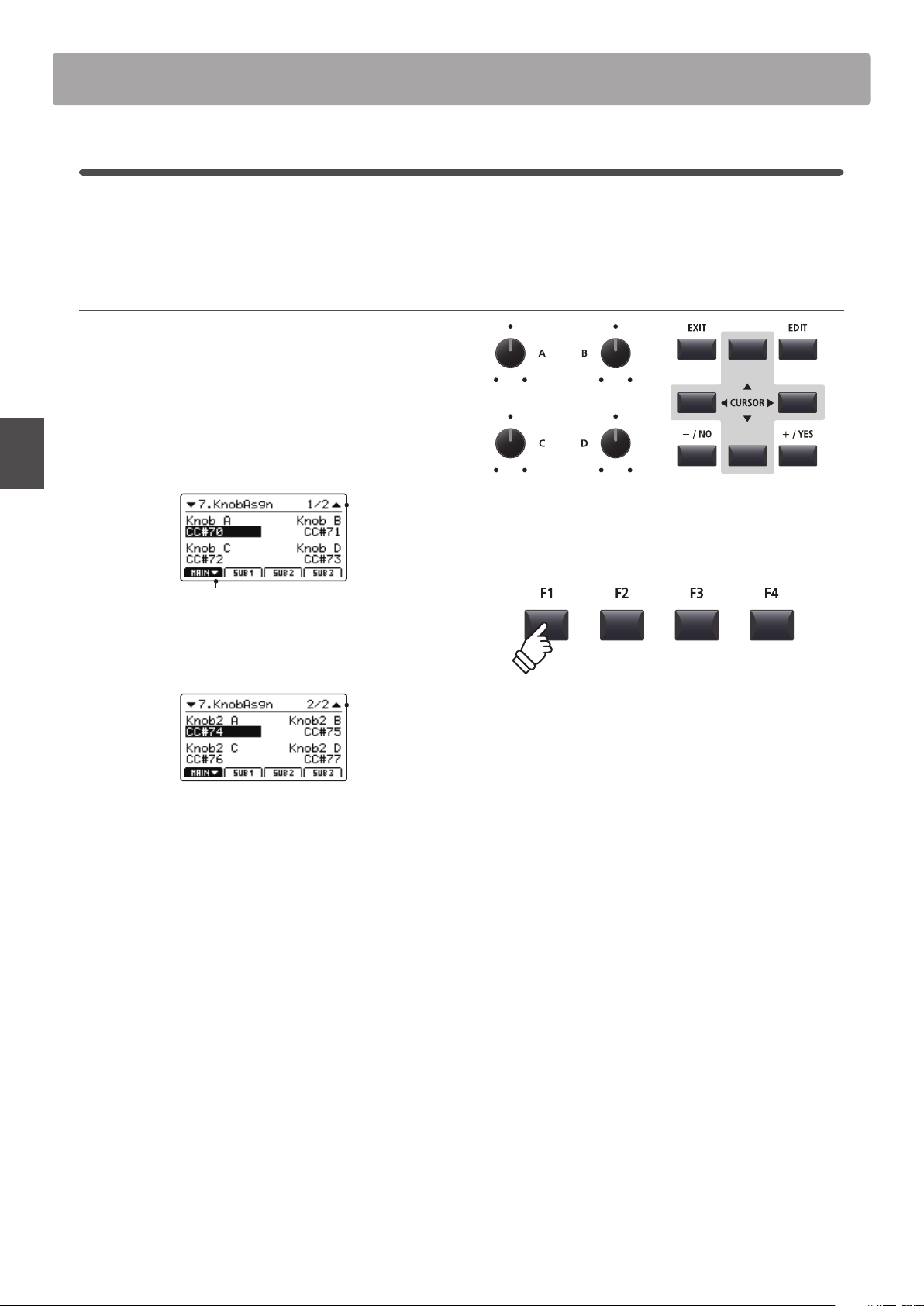
62
EDIT Menu
EDIT Menu parameters (EXT mode)
7
Knob Assign
The Knob Assign screen is used to assign MIDI Control Change or Aftertouch messages to the four main control
knobs A, B, C, and D for direct, real-time adjustment in Play Mode. Two groups of knob parameters (primary and
secondary) can be assigned to each of the four zones, providing extensive control over external MIDI devices.
Assigning MIDI CC/Aftertouch messages to each knob
Enter the Knob Assign screen for the desired section.
Turn the four control knobs (A, B, C, D) to specify which MIDI CC
message should be assigned to each control knob.
MIDI CC messages can also be assigned by using the CURSOR
buttons to move the selection cursor, and +/YES or –/NO
buttons to increase or decrease the values.
Page 1/2
arrow:
Next page
Press the F1~F4 buttons (depending on the selected zone)
to show the secondary group of knob parameters in the LCD
display.
Page 2/2
* For more information about adjusting parameters in Play Mode, please
refer to page 26.
63
EDIT Menu
Overview of the EDIT Menu (BOTH mode)
When a zone is set to BOTH mode, the EDIT menu will display a combination of INT mode and EXT mode parameters.
The rst eight categories will contain normal INT mode parameters, with an additional four categories containing
EXT mode parameters.
* For more information about INT mode and EXT mode parameters please refer to pages 38 and 54.
As with zones set to INT and EXT mode, this collection of parameters, together with other adjustable settings, can
be stored as a SETUP memory (page 65). The MP7SE provides 256 user programmable SETUP memories.
About Common parameters ( icon)
Unless stated, parameter settings for the MAIN, SUB1, SUB2, and SUB3 zones are independent for each zone. However, parameters
marked with a
icon are common for all four zones. For example, changing the Right Pedal Assign parameter for the MAIN zone
will automatically change the
Right Pedal Assign parameter for the SUB1, SUB2, and SUB3 zones.
About System parameters ( icon)
EXT mode zone parameters marked with a icon are SYSTEM parameters and memorised automatically, without the need to use
the STORE function.
BOTH mode zone parameters
No. Category Parameters
INT mode parameters
1 REVERB Type, Pre Delay, Time, Depth
2
EFX Category, Type, Parameters (prm1~prm10, depending on EFX type)
AMP Amp Type, Drive, Level, Amp EQ Lo, Amp EQ Mid, Amp EQ Hi, Mid Freq., Mic Type, Mic Position, Ambience
3 Sound
Volume, Panpot, Filter Cut-o, Filter Resonance, DCA Attack Time, DCA Decay Time, DCA Sustain Level,
DCA Release Time, DCF Attack Time, DCF Attack Level, DCF Decay Time, DCF Sustain Level, DCF Release Time,
DCF Touch Depth, DCA Touch Depth, Vibrate Depth, Vibrate Rate, Vibrate Delay, Octave Layer Switch,
Octave Layer Level, Octave Layer Range, Octave Layer Detune, Portamento, Porta. Time, Porta. Mode
tonewheel: Drawbar Position, Percussion, Perc. Level, Perc. Decay, Perc. Harmonic, Volume, Ext. Control
4 Tuning Fine Tune, Stretch Tuning, Temperament, Key of Temperament
5 Key Setup
Touch Curve, Dynamics, Trigger Mode, Minimum Touch, Octave Shift, Zone Transpose, Key Scaling Damping,
Key Scaling Key, Key Range Zone Lo, Key Range Zone Hi, Velocity Switch, Velocity Switch Value, Solo,
Solo Mode, Key Volume
6 Controllers
Damper Pedal,
Damper Pedal Assign, Damper Pedal Mode, Pitch Bend, P. Bend Range, Soft Pedal Depth,
Modulation Wheel, Modulation Wheel Assign, Modulation Depth Range, SW1 Button,
SW1 Button Assign,
SW2 Button,
SW2 Button Assign, Footswitch Pedal, Footswitch Pedal Assign, Expression Pedal,
Expression Pedal Assign, Right Pedal, Right Pedal Assign, Center Pedal, Center Pedal Assign, Left Pedal,
Left Pedal Assign
7 Knob Assign
Knob A Assign, Knob B Assign, Knob C Assign, Knob D Assign,
Knob2 A Assign, Knob2 B Assign, Knob2 C Assign, Knob2 D Assign
8
Virtual
Technician
piano: Voicing, String Resonance, Undamped Resonance, Damper Resonance, Key-o Eect, Damper Noise,
Hammer Delay, Fall-back Noise, Topboard, Stereo Width
e.piano/harpsi/bass: Key-o Noise, Key-o Delay
drawbar*: Key Click Level, Wheel Noise Level
EXT mode
9 Ch/Program MIDI Transmitting Channel, Program*, Bank MSB*, Bank LSB*
10 SETUP Send Program, Send Bank, Send Volume, Send Knobs
11 Transmit
Transmit System Exclusive, Transmit Recorder
12 MMC
Transmit MMC, MMC Device ID, MMC Commands
* When a zone is set to BOTH mode, the Program, Bank MSB, and Bank LSB parameters are xed, and cannot be adjusted.
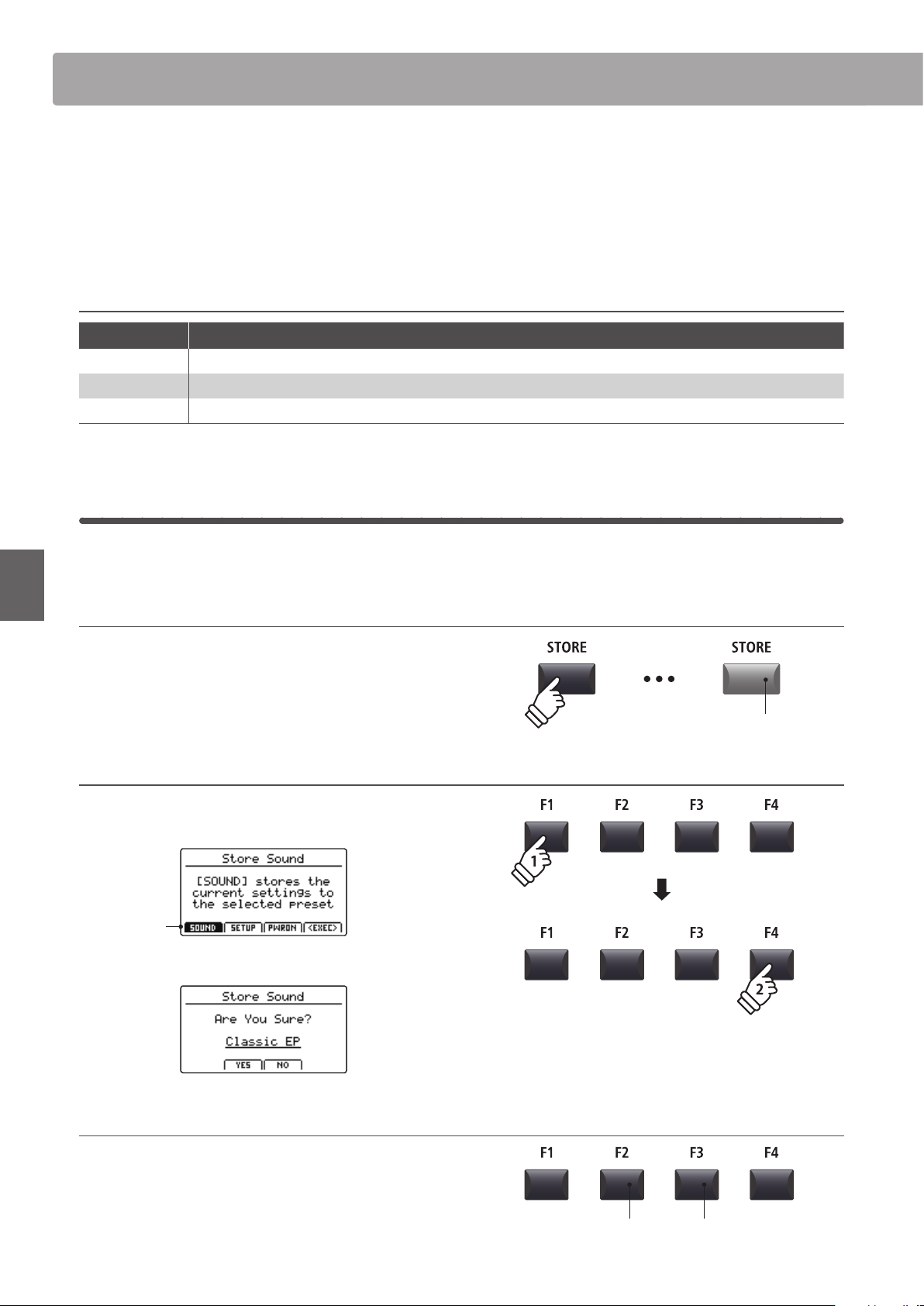
64
STORE Button & SETUPs
After using the EDIT menu and control knobs to adjust the parameters for the selected sound/zone, the STORE
button is used to memorise the settings, and ensure the changes are not lost when turning the instrument OFF or
selecting other sounds.
The STORE button has three dierent functions: to store individual sounds (SOUND), to store the entire panel
conguration (SETUP), and to store the current panel conguration as the default (POWERON).
STORE button functions
STORE function Description
SOUND Store the selected sound’s EDIT menu parameters* to the variation button.
SETUP Store all EDIT menu parameters, all sound section panel settings, and EQ section settings to a SETUP memory.
POWERON Store all EDIT menu parameters, all sound section panel settings, and EQ section settings as the default.
* Common parameters are not stored to SOUND memory. For more information about common parameters, please refer to page 38.
1
Storing a SOUND
This function will store the selected sound’s EDIT menu parameters to the variation button, thus overwriting the
existing preset sound.
1. Entering the STORE screen
Press the STORE button.
The LED indicator for the STORE button will turn ON, and the
store selection screen will be shown in the LCD display.
2. Selecting the Store Sound function
Press the F1 button (SOUND) to select the Store Sound function,
then press the F4 button (EXEC).
SOUND
selected
The Store Sound conrmation screen will be shown in the LCD display.
3. Conrming the Store Sound operation
Press the F2 button (YES) to conrm the Store Sound operation,
or the F3 button (NO) to return to the store selection screen.
* The existing sound will be overwritten with the adjusted sound.
* The +/YES and –/NO buttons can also be used to conrm or cancel the
store operation.
LED indicator ON:
STORE mode is selected
F3 button:
NO: Cancel
F2 button:
YES: Conrm
Overview of the STORE Button
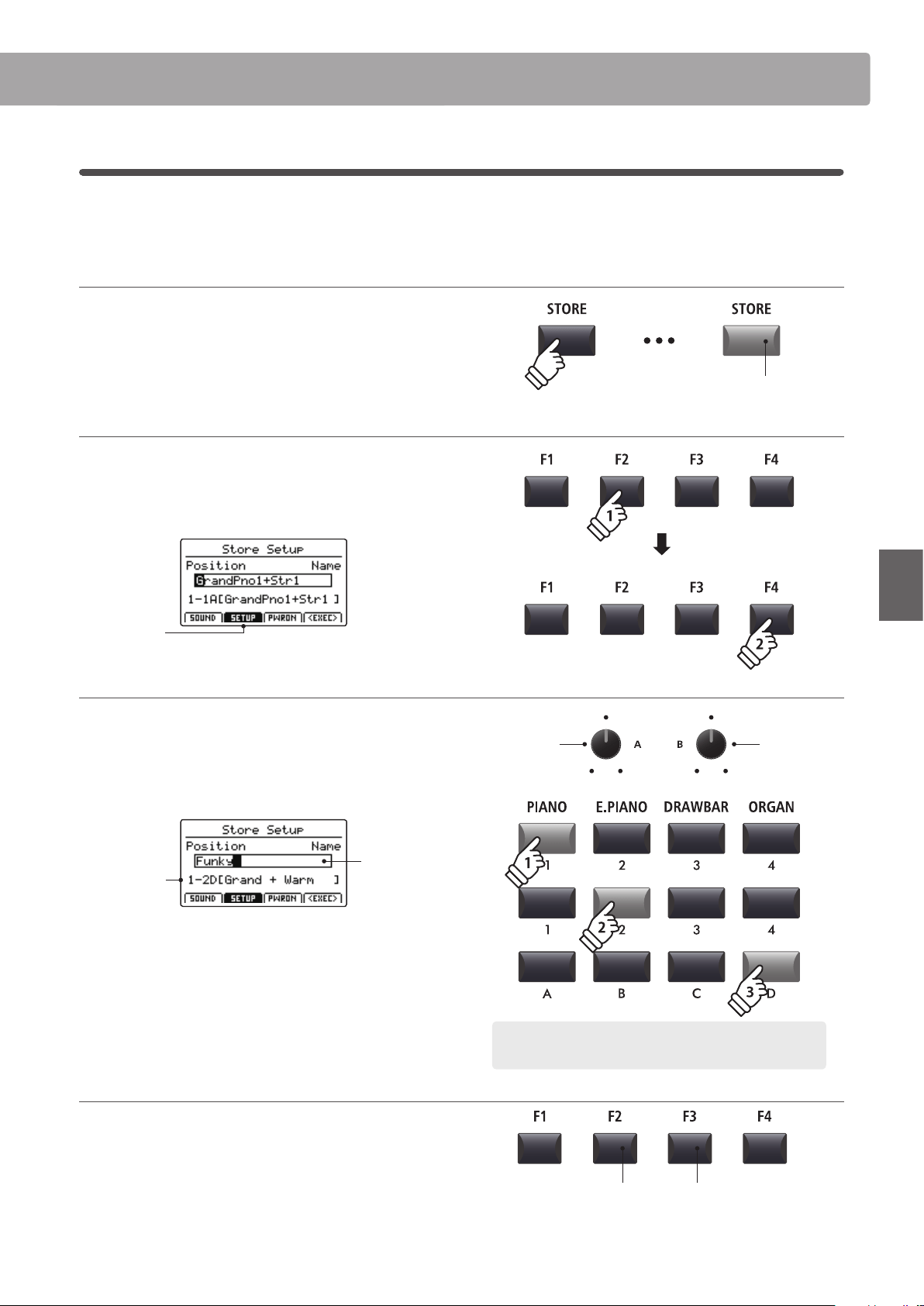
65
STORE Button & SETUPs
Overview of the STORE Button
2
Storing a SETUP
This function will store all the EDIT menu parameters for the MAIN and SUB zones, panel button and knob states,
and EQ settings to one of the MP7SE’s 256 SETUP memories.
1. Entering the STORE screen
Press the STORE button.
The LED indicator for the STORE button will turn ON, and the
store selection screen will be shown in the LCD display.
2. Selecting the Store Setup function
Press the F2 button (SETUP) to select the Store Setup function,
then press the F4 button (EXEC).
The Store Setup screen will be shown in the LCD display.
SETUP
selected
3. Naming the SETUP, selecting the SETUP memory
Turn control knobs A and B to move the cursor position and
select the characters for the SETUP name.
Press the SETUP memory buttons to select the memory location
for the new SETUP.
SETUP
memory
SETUP
name
Press the F4 function button (EXEC).
The Store Setup conrmation screen will be shown in the LCD
display.
4. Conrming the Store Setup operation
Press the F2 button (YES) to conrm the Store Setup operation,
or the F3 button (NO) to return to the previous screen.
* The existing SETUP memory will be overwritten with the new SETUP.
* The +/YES and –/NO buttons can also be used to conrm or cancel the
store operation.
* When the SETUP has been stored and the SETUP button has been turned
OFF, the panel settings will return to the POWERON state.
LED indicator ON:
STORE mode is selected
Move cursor
position
Select
character
Example: To select SETUP memory 1-2D, press ‘PIANO’ category
button, the ‘2’ sub-category button, and the ‘D’ variation button.
F3 button:
NO: Cancel
F2 button:
YES: Conrm
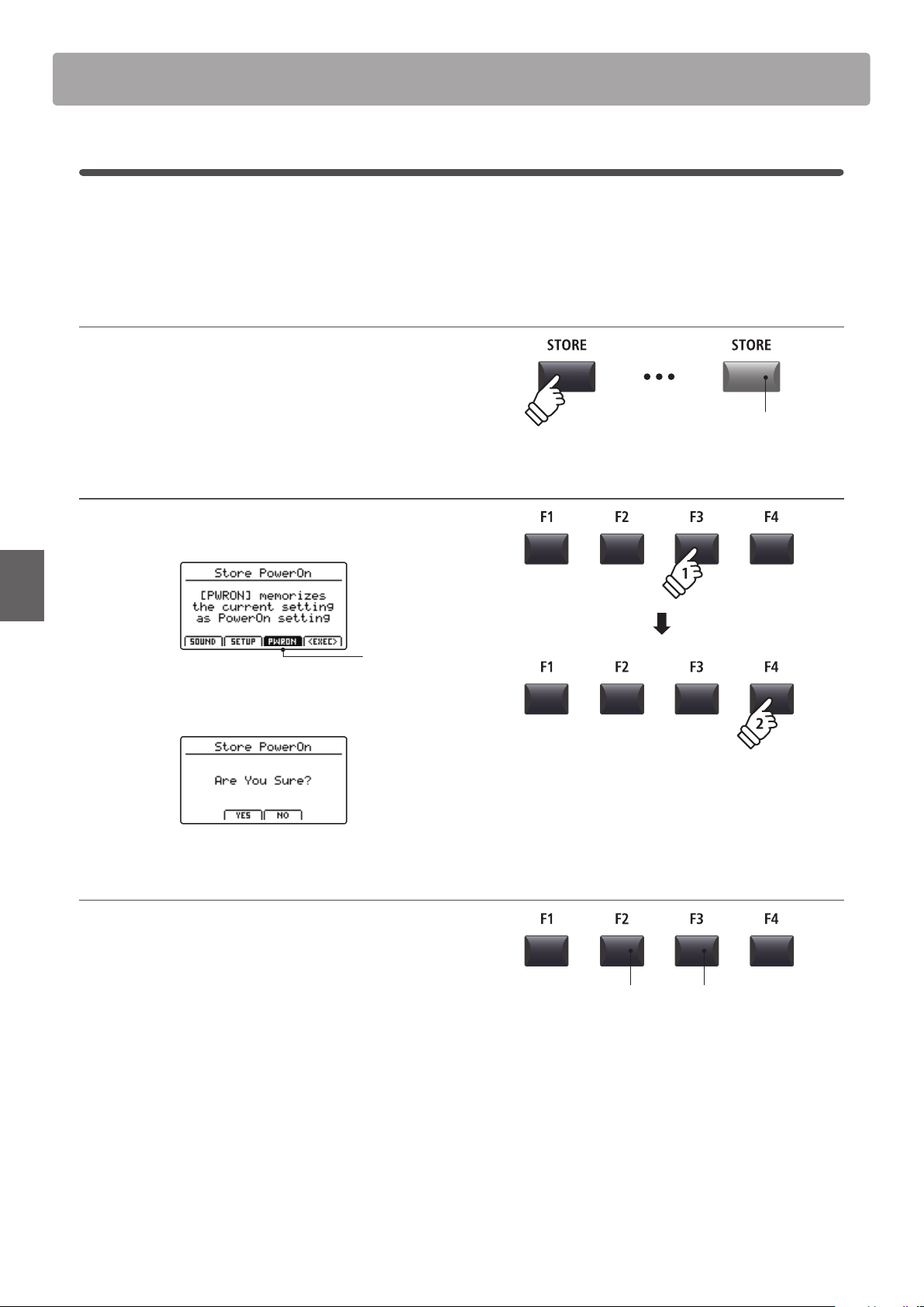
66
STORE Button & SETUPs
Overview of the STORE Button
3
Storing POWERON settings
This function will store the EQ setting and current state (Zone ON/OFF, selected sound) of all four zones to the
MP7SE’s default POWERON memory.
* Please note that only the selected SOUND position (e.g. SK Concert Grand) will be stored to POWERON memory, not the individual EDIT menu settings (e.g.
String Resonance) of that SOUND.
1. Entering the STORE screen
Press the STORE button.
The LED indicator for the STORE button will turn ON, and the
store selection screen will be shown in the LCD display.
2. Selecting the Store PowerOn function
Press the F3 function button (PWRON) to select the Store
PowerOn function, then press the F4 button (EXEC).
POWERON
selected
The Store PowerOn conrmation screen will be shown in the
LCD display.
3. Conrming the Store PowerOn operation
Press the F2 button (YES) to conrm the Store PowerOn
operation, or the F3 (NO) button to return to the previous
screen.
* The existing POWERON memory will be overwritten.
* The +/YES and –/NO buttons can also be used to conrm or cancel the
store operation.
* Please note that only the selected SOUND position (e.g. SK Concert
Grand) will be stored to POWERON memory, not the individual EDIT menu
settings (e.g. String Resonance) of that SOUND.
In order to memorise EDIT menu settings for a SOUND, please use the
Store SOUND function. (see page 64)
LED indicator ON:
STORE mode is selected
F3 button:
NO: Cancel
F2 button:
YES: Conrm
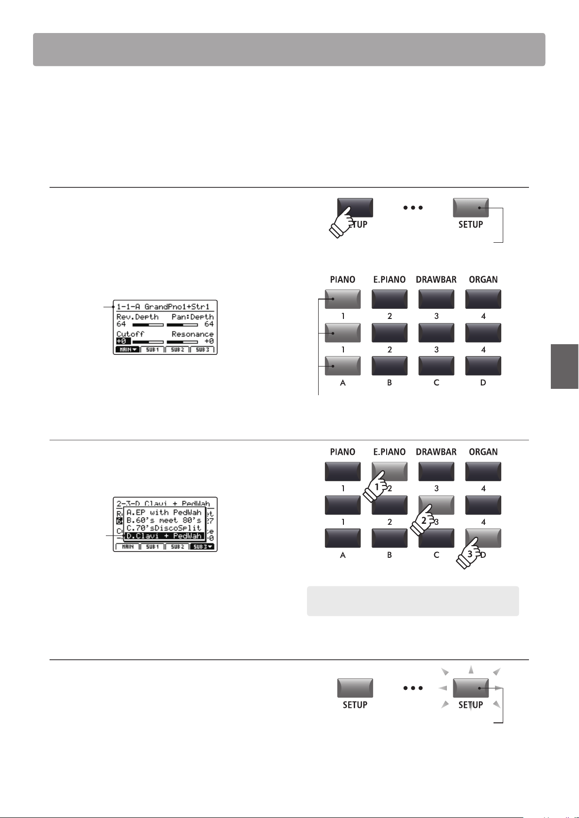
67
STORE Button & SETUPs
The MP7SE’s SETUP memories allow the entire instrument conguration, including selected sounds, section volume
levels, parameter settings, and EQ adjustments, etc. to be stored and recalled immediately at the touch of a button.
SETUPs are arranged in an 8x8x4 conguration, allowing for a total of 256 individual memories.
This page explains how to select SETUP mode and recall and edit a SETUP memory.
Selecting SETUP mode
Press the SETUP button to select SETUP mode.
The LED indicator for the SETUP button will turn on to indicate
that SETUP mode is selected.
The LED indicators for the currently selected SETUP memory
buttons will also turn on, and the name of the SETUP memory
will be shown in the LCD display.
Selected
SETUP
* The previously selected SETUP memory will be recalled automatically.
* To check which sounds are assigned to each zone, press and hold the
desired F1~F4 function button.
Selecting SETUPs
While SETUP mode is turned ON:
Press the SETUP memory buttons to select the desired SETUP
memory.
Selected
SETUP
* In order to prevent abrupt ‘breaks’ in sound, the selected SETUP will not
be applied immediately (i.e. when the button is pushed), but with the next
key press. This allows subsequent SETUPs to be selected while the notes
of the existing SETUP are held/sustained, resulting in a smooth transition
between songs/sequences etc.
Editing SETUPs
While SETUP mode is turned ON:
Press the EDIT buttons to edit the selected SETUP memory.
The LED indicator for the SETUP button will start to ash, to
indicate that the SETUP memory is being edited.
In addition, the LED indicators for the SOUND and sound
selection buttons will also turn on, to indicate which sound is
assigned to the currently selected zone.
LED indicator ON:
SETUP mode is turned ON
LED indicator ON:
Selected SETUP buttons
SETUP Memories
Example: To select SETUP memory 2-3D, press ‘E.PIANO’ category
button, the ‘3’ sub-category button, and the ‘D’ variation button.
LED indicator ashing:
SETUP is being edited
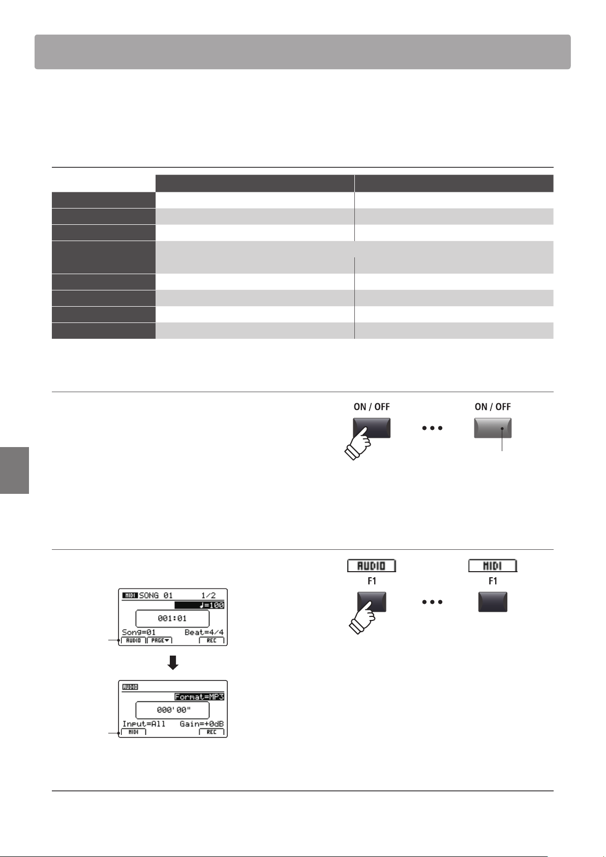
68
Recorder
The MP7SE’s Recorder features convenient functions to record and playback performances from the instrument’s
internal memory or a connected USB memory device. The characteristics of each method are outlined below.
MP7SE Recorder characteristics
Song Recorder (Internal Memory) Audio Recorder (USB Memory)
Stored/saved format SMF (MIDI) MP3/WAV (audio)
Maximum song length 90,000 notes Depends on device capacity
Maximum no. of songs 10 songs Depends on device capacity
Example applications Sketching ideas, recording nished performances, remixing and further editing on a computer.
Emailing to friends, burning to audio CD, etc.
Playback methods Playback songs on MP7SE and other MIDI devices Playback songs on MP7SE and audio players etc.
Adjustable tempo Yes, before and during playback No
Overdubbing No Yes, unlimited overdubs
Conversion options Can be converted to MP3/WAV Cannot be converted to SMF (MIDI)
Turning Recorder mode ON or OFF
Press the RECORDER section’s ON/OFF button to turn Recorder
mode ON or OFF.
The LED indicator for the RECORDER section’s ON/OFF button
will turn ON or OFF accordingly.
When Recorder mode is turned ON, the recorder screen will be
shown in the LCD display.
Selecting the Recorder mode
Press the F1 function button to alternate between the Internal
Song Recorder and the USB Audio Recorder functions.
AUDIO:
Show audio
recorder
MIDI:
Show MIDI
recorder
USB Functions
Additional USB functions to delete and rename les stored on USB memory devices can be found in the USB Menu. For information
about USB functions, please refer to page 99.
LED indicator ON:
Recorder mode is turned ON
* If a USB memory device is connected when Recorder mode is turned ON,
the USB Audio Recorder function will be selected automatically.
* If a USB memory device is not connected when Recorder mode is turned
ON, the Internal Song Recorder function will be selected automatically.
Overview of the Recorder
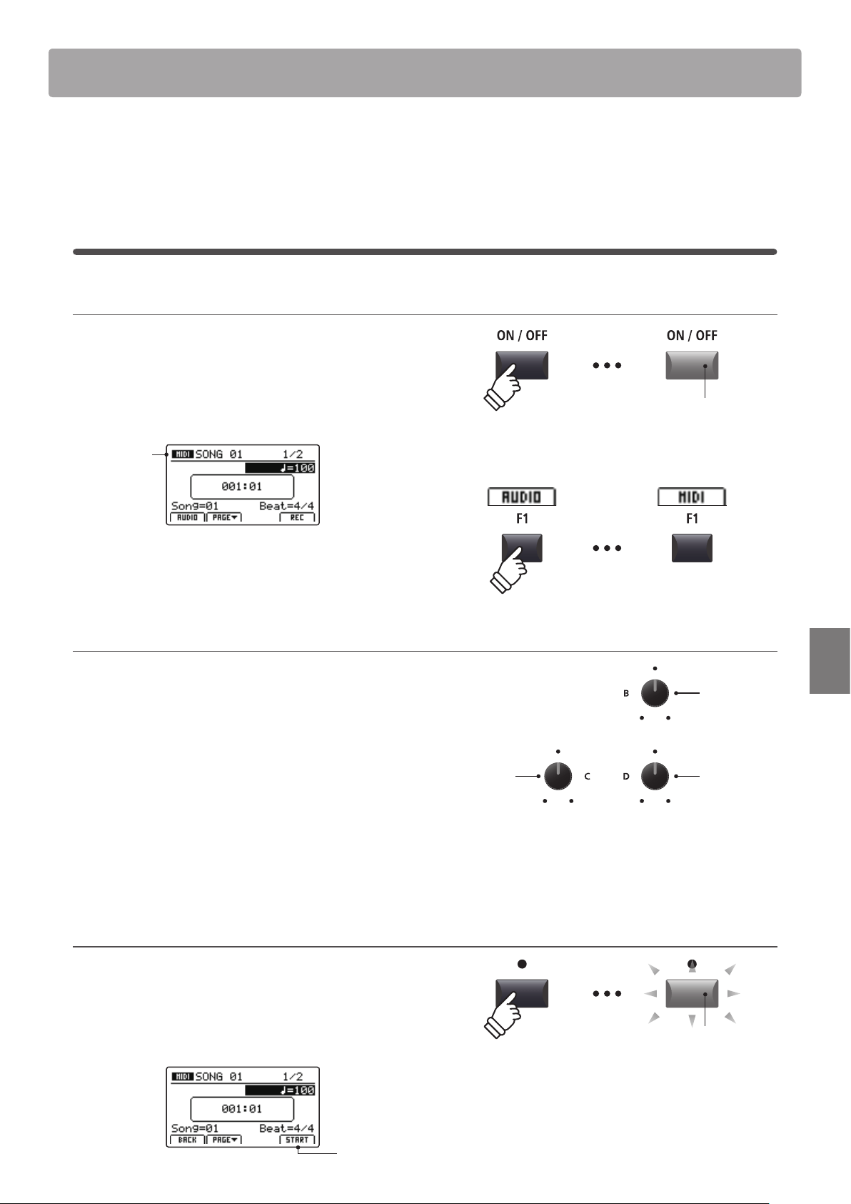
69
Recorder
Song Recorder (Internal memory)
The Song Recorder function allows up to 10 dierent songs to be recorded, stored in internal memory, and played
back at the touch of a button. Once recorded, songs can be saved to USB memory in Standard MIDI File (SMF)
format, or converted to MP3/WAV audio les.
1
Recording a song
1. Turning the Recorder mode ON
Press the RECORDER section’s ON/OFF button to turn Recorder
mode ON.
The LED indicator for the RECORDER section’s ON/OFF button
will turn ON, and the MIDI recorder screen will be shown in the
LCD display.
MIDI
recorder
selected
If a USB memory device is connected, press the F1 button (MIDI) to
select the MIDI recorder function.
2. Selecting the song memory, adjusting tempo/beat
Turn control knob C to select the song memory to be used for
the new recording.
* There are 10 internal song recorder memories.
* If the selected song memory already contains recording data, it will be
erased automatically when the new song is recorded
.
If recording with the metronome or a drum rhythm:
Turn control knobs B and D to adjust the tempo and beat (time
signature) or drum rhythm used for the new recording.
* For more information about recording with the metronome or drum
rhythms, please refer to page 97.
3. Starting the song recorder (standby mode)
Press the recorder control button.
The LED indicator for the button will start to ash, to indicate
that the recorder is in standby mode.
* The F4 function button (REC) can also be used to engage standby mode.
Standby
mode
LED indicator ON:
Recorder mode is turned ON
Song
memory
Time
signature
Tempo
LED indicator ashing:
Recorder is in standby mode
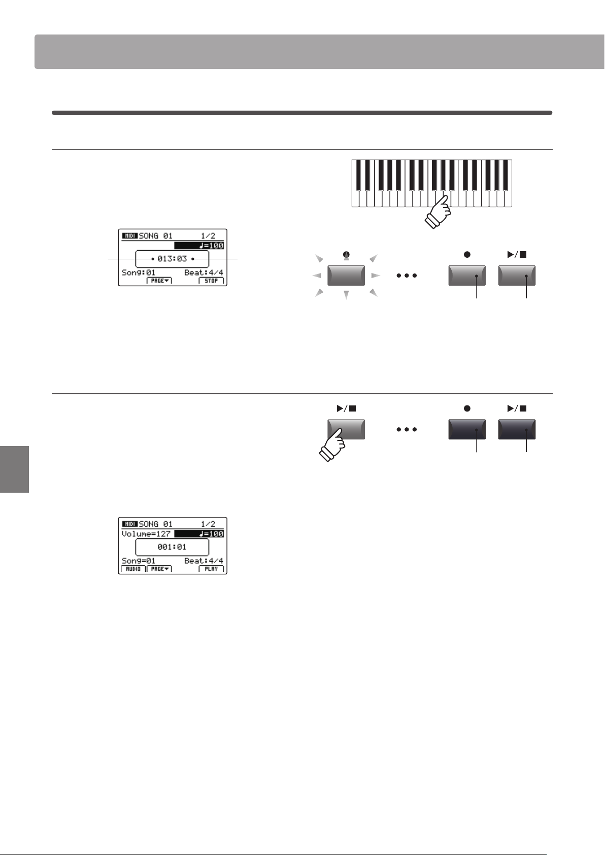
70
Recorder
Song Recorder (Internal memory)
4. Starting the song recorder (recording)
Press a key on the keyboard.
The LED indicators for the and / buttons will turn ON, the
bar/beat counter shown in the centre of the LCD will begin to
increase, and recording will start.
Bar
(of song)
Beat
(of bar)
* Recording can also be started by pressing the / button. This allows a
rest period or empty bar to be inserted at the beginning of the song.
* The metronome can be enabled before recording to assist with timing etc.
When enabled, a one bar count-in will be added before recording begins.
5. Stopping the song recorder
Press the / recorder control button.
The LED indicators for the and / buttons will turn OFF, and
recording will stop.
* The F4 function button (STOP) can also be used to stop recording.
After a brief pause, the MIDI player screen will be shown in the
LCD display.
For information about playing the recorded song, please refer to
page 71.
LED indicators ON:
Recording is in progress
LED indicators OFF:
Recording has stopped
* The maximum recording capacity is approximately 90,000 notes, with
button and pedal presses also counted as one note.
* If the maximum recording capacity is reached during recording, the
recorder will stop automatically.
* To prevent data loss, avoid turning the power OFF while the MP7SE is
saving internal recorder songs.
* Recorder songs will remain in memory after the power is turned OFF.
1
Recording a song (cont.)
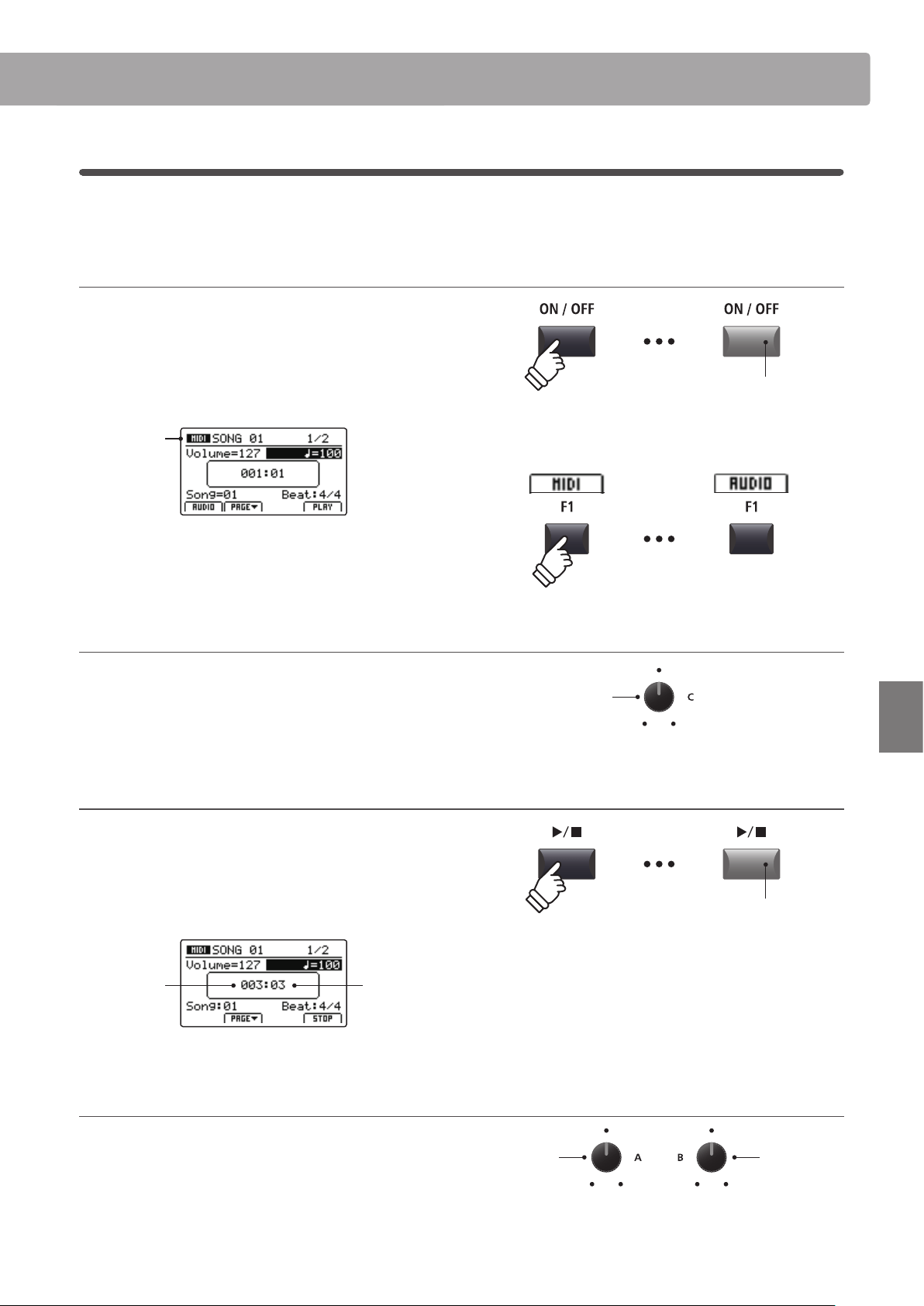
71
Recorder
Song Recorder (Internal memory)
2
Playing back a song
This function is used to playback recorder songs stored in internal memory. To playback a song immediately after
recording, start this process from step 3.
1. Turning the Recorder mode ON
Press the RECORDER section’s ON/OFF button to turn Recorder
mode ON.
The LED indicator for the RECORDER section’s ON/OFF button
will turn ON, and the MIDI recorder screen will be shown in the
LCD display.
MIDI
recorder
selected
If a USB memory device is connected, press the F1 button (MIDI) to
select the MIDI recorder function.
2. Selecting the song to playback
Turn control knob C to select the song memory to be played
back.
* Song selection is not possible during playback.
3. Starting song playback
Press the / recorder control button.
The LED indicator for the / button will turn ON, and the
selected song will start to play.
* The F4 function button (PLAY) can also be used to start song playback.
Bar
(of song)
Beat
(of bar)
Adjusting playback volume and tempo
Turn control knobs A and B to adjust the playback volume and
tempo of the song.
* The playback volume and tempo of the song can be adjusted both before
and during playback.
LED indicator ON:
Recorder mode is turned ON
Song
memory
Playback
volume
Tempo
LED indicator ON:
Playback is in progress
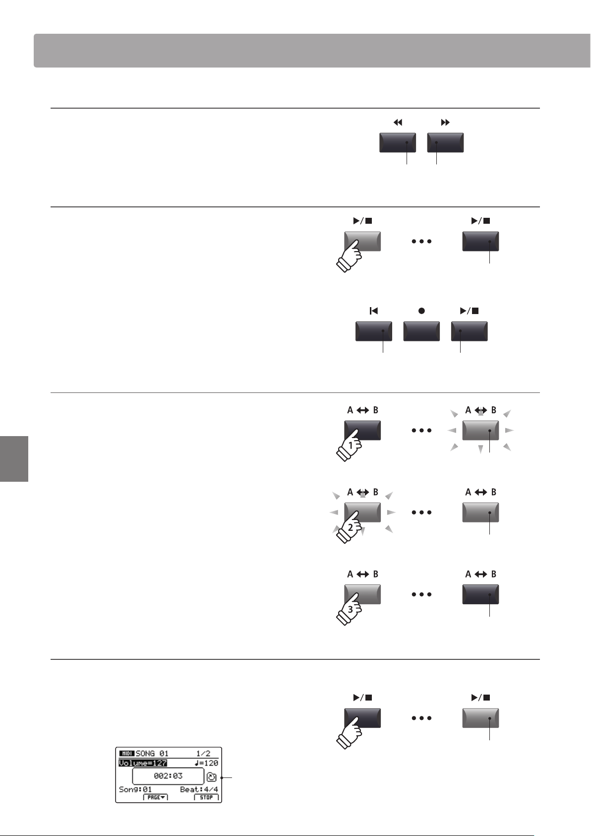
72
Recorder
Song Recorder (Internal memory)
Moving the playback position (seek)
Press the or recorder control buttons to move the
playing position of the song backward and forward in single bar
increments.
* The playback position can be moved both before and during playback.
4. Stopping song playback
While a song is playing:
Press the / recorder control
button.
The LED indicator for the / button will turn OFF, and song
playback will stop.
* The F4 function button (STOP) can also be used to stop song playback.
Press the / button again to continue playback from the stopped
position, or the
button to reset the playback position to the
beginning of the song.
A-B Repeat function
The A-B Repeat function allows one section of a song to be repeated
continuously (looped). This function can be activated both before
and during song playback.
Press the A B recorder control button once to set the start
point of the loop.
The LED indicator for the A B button will start to ash.
Press the A B button again to set the end point of the loop.
The LED indicator for the A B button will turn ON and the
specied section will repeat continuously.
Press the A B button once again to cancel the loop.
The LED indicator for the A B button will turn OFF and normal
playback will resume.
Chain Play mode
Chain Play mode allows all recorder songs stored in memory to be played continuously, in sequence.
Press and hold the / recorder control button.
The Chain Play icon will be shown in the LCD display, and the
recorder songs will start to play continuously, in sequence.
Chain Play
activated
LED indicator ON:
Playback is in progress
button:
Next bar
button:
Previous bar
button:
Reset position
/ button:
Resume playback
LED indicator OFF:
Playback has stopped
LED indicator ashing:
Start point of the loop set
LED indicator ON:
End point of the loop set, loop activated
LED indicator OFF:
Loop deactivated, normal playback resumes
hold
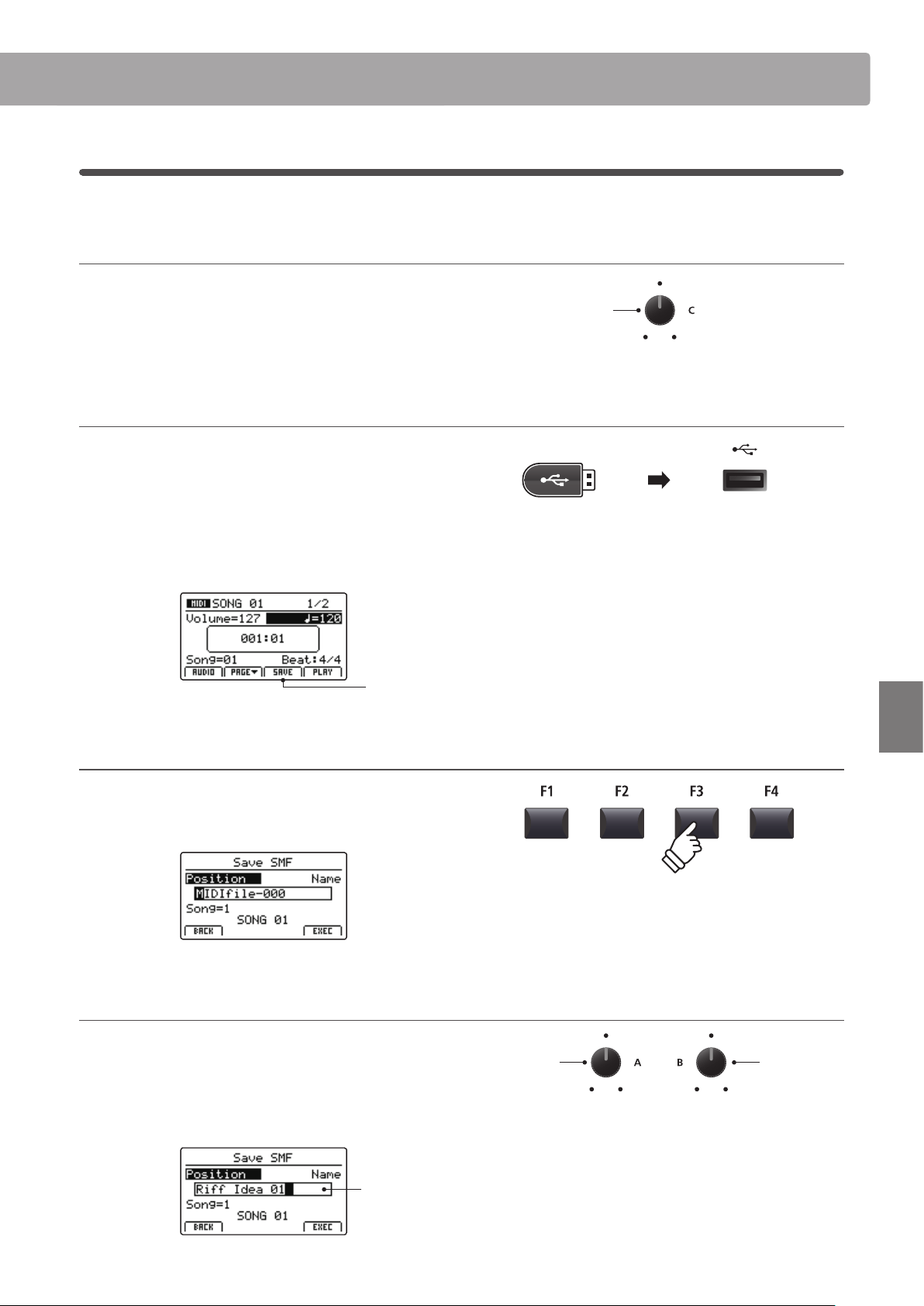
73
Recorder
Song Recorder (Internal memory)
3
Saving a song as an SMF le
This function is used to save recorder songs to a USB memory device in SMF (Standard MIDI File) format.
1. Selecting the song memory
After turning Recorder mode ON, and recording a song:
Turn control knob C to select the song memory to be saved to
the USB memory in SMF format.
2. Connecting a USB memory device
Connect a USB memory device to the USB to Device port.
* USB devices should be formatted to use the ‘FAT’ or ‘FAT32’ lesystems.
The USB device will be scanned, and the SAVE function will
appear at the bottom of the LCD display.
* The SAVE function will appear only when the selected song memory has
been recorded to.
Save
function
3. Selecting the Save SMF function
Press the F3 function button (SAVE).
The Save SMF screen will be shown in the LCD display.
4. Entering a lename
Turn control knobs A and B to move the cursor position and
select the characters for the song name.
* Saved SMF les are limited to a maximum name length of 18 characters.
* The saved SMF le will be stored in the root folder of the USB memory
device. It is not possible to store the le in a dierent folder.
Song
name
Move cursor
position
Select
character
Song
memory
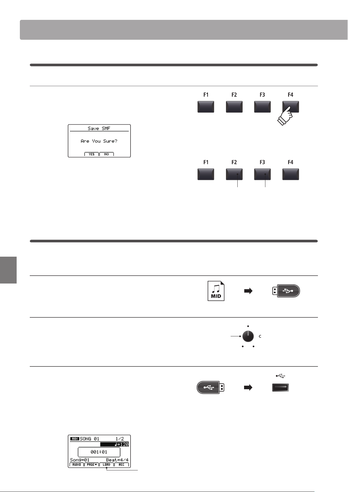
74
Recorder
Song Recorder (Internal memory)
5. Saving the song
Press the F4 function button (EXEC).
The Save SMF conrmation screen will be shown in the LCD
display.
Press the F2 button (YES) to conrm the Save SMF operation, or
the F3 button (NO) to return to the previous screen.
* The +/YES and –/NO buttons can also be used to conrm or cancel the
save operation.
* To prevent data loss, avoid turning the power OFF while the MP7SE is
saving les to USB memory.
4
Loading an SMF le into memory
This function can be used to load SMF les into an empty recorder song memory.
Preparing the USB memory device
Prepare a selection of SMF MIDI les, copying the data to a USB
memory device.
1. Selecting an empty song memory
After turning Recorder mode ON:
Turn control knob C to select an empty song memory.
2. Connecting a USB memory device
Connect a USB memory device to the USB to Device port.
* USB devices should be formatted to use the ‘FAT’ or ‘FAT32’ lesystems.
The USB device will be scanned, and the LOAD function will
appear at the bottom of the LCD display.
* The LOAD function will appear only when the selected song memory is
empty. For information about erasing song memories, please refer to
page 77.
Load
function
F3 button:
NO: Cancel
F2 button:
YES: Conrm
Song
memory
3
Saving a song as an SMF le (cont.)
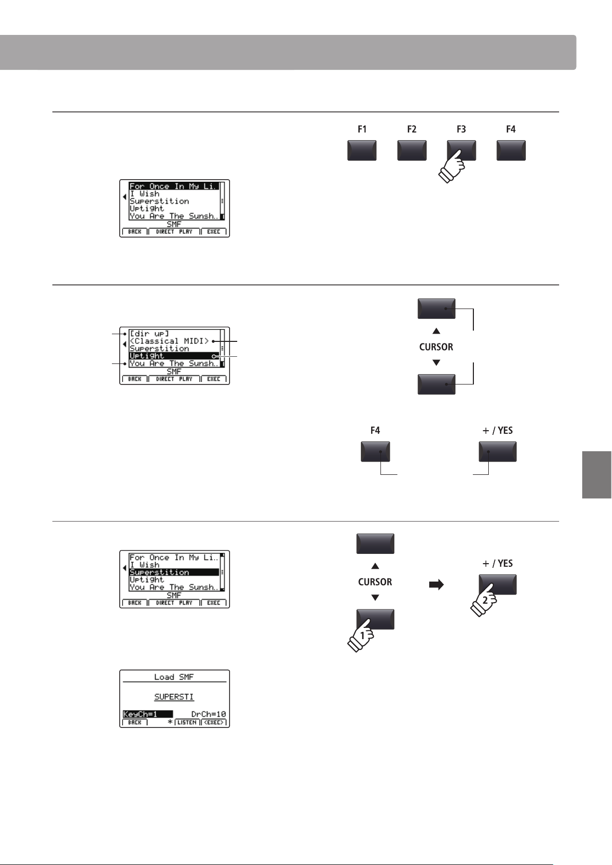
75
Recorder
Song Recorder (Internal memory)
3. Selecting the Load SMF function
Press the F3 function button (LOAD).
A listing of the SMF les stored in the root folder of the USB
device will be shown in the LCD display.
USB device le/folder listing screen
The MP7SE’s le/folder listing screen lists relevant les and
folders stored in the root of the USB device.
Previous
folder
Folder
File
Selection
cursor
Press the CURSOR buttons to move the selection cursor.
* Control knob A can also be used to move the selection cursor.
Press the F4 function button (EXEC) or +/YES button to select
the le or enter the selected folder.
4. Selecting the SMF le to load
Press the CURSOR buttons to select the desired MIDI le.
Press the F4 function button (EXEC) or +/YES button.
The Load SMF screen will be shown in the LCD display.
Move
selection
cursor
or
Select le/folder
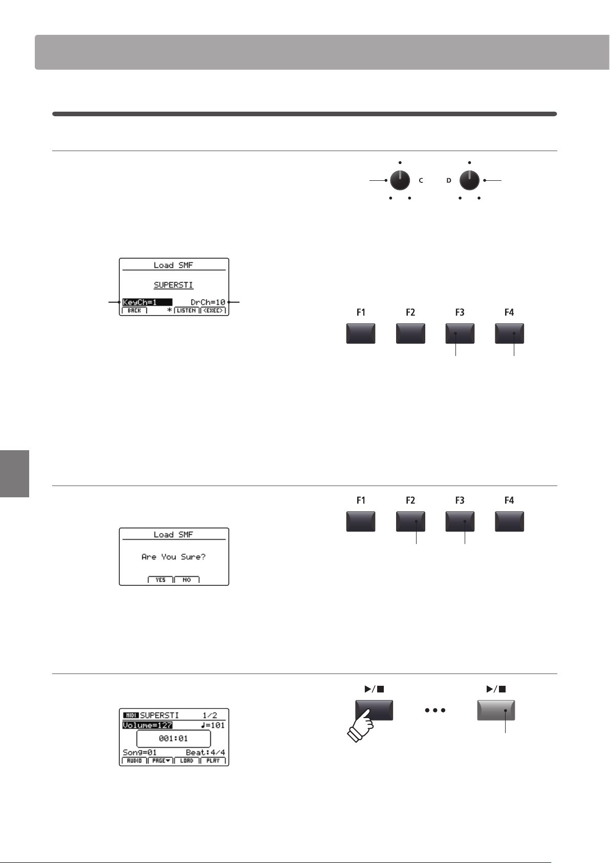
76
Recorder
Song Recorder (Internal memory)
5. Selecting the keyboard and drum channels
Turn control knobs C and D to specify which channels of the
SMF le should be loaded into the MP7SE recorder’s keyboard
and drum tracks.
* The MP7SE will attempt to detect the correct keyboard and drum tracks
automatically, based on the contents of the SMF le.
* When loading an SMF le created by the MP7SE, the drum track will be
turned OFF.
Drum
channel
Keyboard
channel
Press the F3 function button (LISTEN) to audition the current
channel settings.
Press the F4 function button (EXEC) to load the selected SMF le
into the song memory.
The Load SMF conrmation screen will be shown in the LCD
display.
6. Conrming the Load SMF operation
Press the F2 button (YES) to conrm the Load SMF operation, or
the F3 (NO) button to return to the previous screen.
* The +/YES and –/NO buttons can also be used to conrm or cancel the
load SMF operation.
7. Playing the loaded SMF le
After loading the SMF le, the recorder screen will be shown in the
LCD display.
For more information about playing the loaded MIDI le, please
refer to page 71.
Keyboard
channel
Drum
channel
F3 button:
Audition settings
F4 button:
Load le
F3 button:
NO: Cancel
F2 button:
YES: Conrm
LED indicator ON:
Playback is in progress
4
Loading an SMF le into memory (cont.)
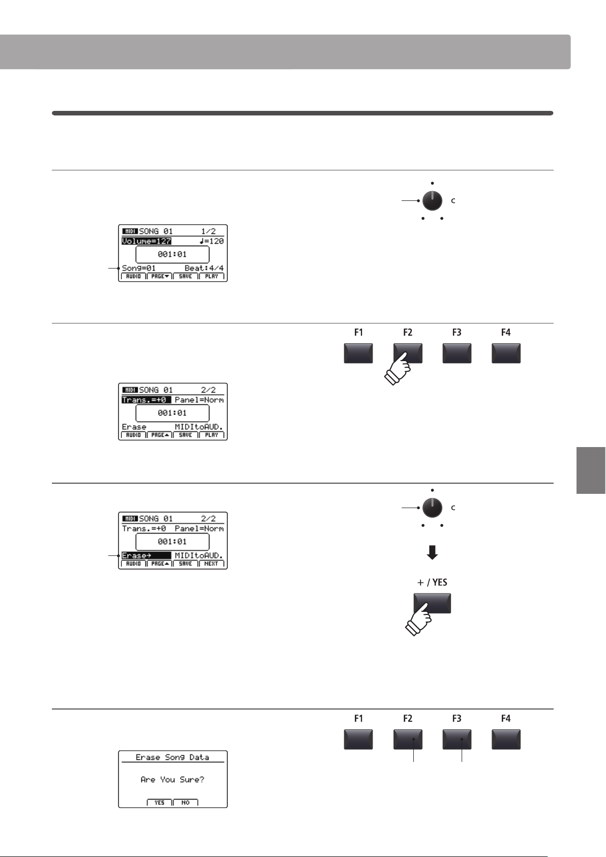
77
Recorder
Song Recorder (Internal memory)
5
Erasing a song
This function is used to erase songs that have been recorded incorrectly, or are simply no longer required.
1. Selecting the song to erase
After turning Recorder mode ON and recording a song:
Turn control knob C to select the song memory to be erased.
Song
memory
2. Showing the additional recorder functions
Press the F2 function button (PAGE).
An additional page of recorder functions will be shown in the
LCD display.
3. Selecting the Erase Song function
Turn control knob C to highlight the Erase Song function.
Erase
highlighted
* The CURSOR buttons can also be used to move the selection cursor.
Press the +/YES button to select the Erase Song function.
The Erase Song conrmation screen will be shown in the LCD
display.
4. Conrming the Erase Song operation
Press the F2 button (YES) to conrm the Erase Song operation,
or the F3 (NO) button to return to the previous screen.
Song
memory
Erase Song
function
* The +/YES and –/NO buttons can also be used to conrm or cancel the
Erase Song operation.
F3 button:
NO: Cancel
F2 button:
YES: Conrm
* To erase all recorder songs, use the Reset Recorder function in the Reset
category of the SYSTEM menu (page 117).
* It is also possible to select the Erase Song function at any time by pressing
the and / recorder control buttons simultaneously.
* The CURSOR buttons can also be used to alternate between pages.
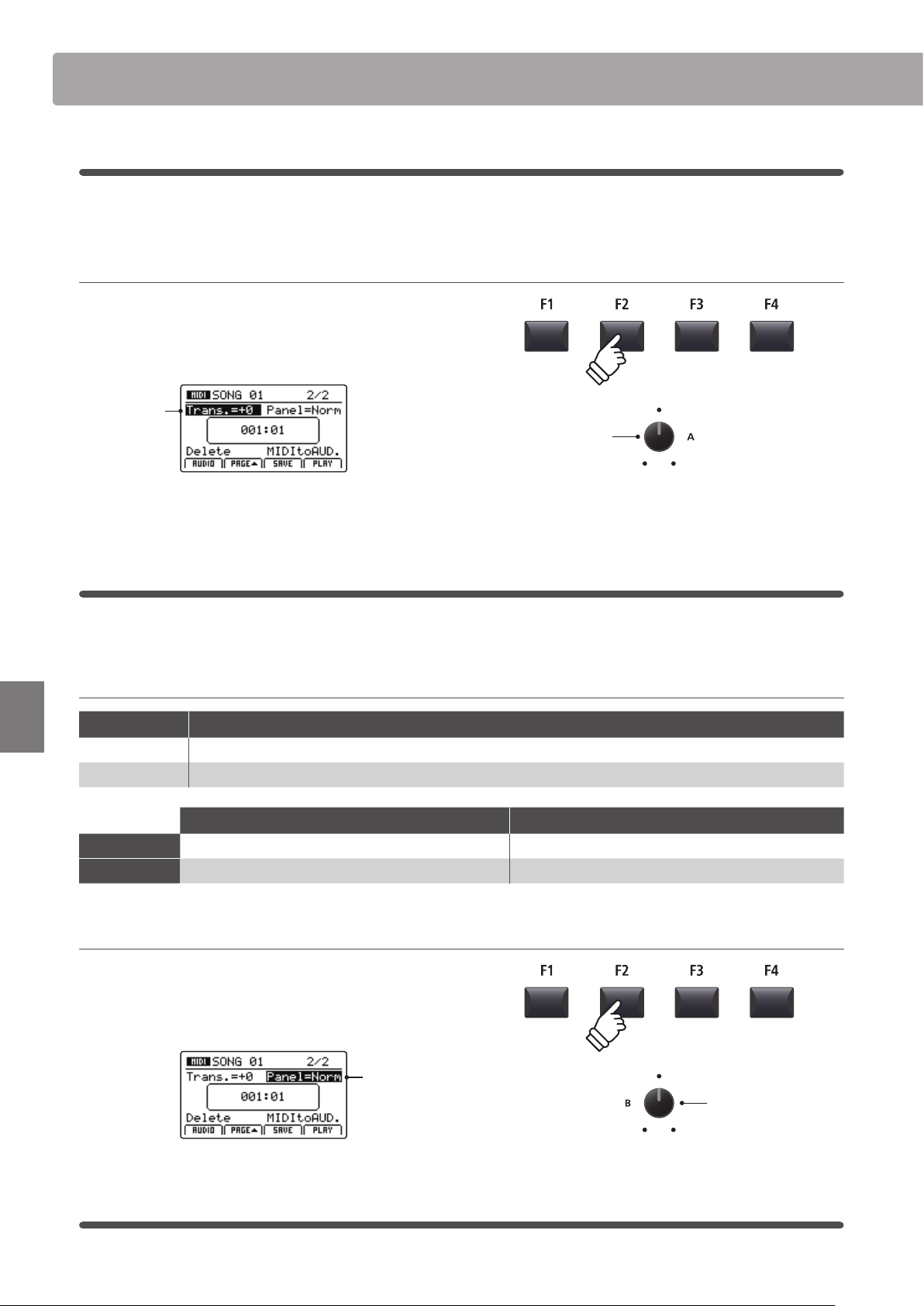
78
Recorder
Song Recorder (Internal memory)
6
Song Transpose
This parameter allows the playback pitch of songs stored in memory to be raised or lowered in semi-tone steps.
This may be useful when wishing to transpose a loaded SMF le into another key.
Changing the song transpose value
Press the F2 function button (PAGE) to show the second page
of recorder functions.
Turn control knob A to change the song transpose value.
Song
transpose
* The Song Transpose value can be adjusted within the range of –12 ~ +12.
7
Panel Mode
This parameter determines whether or not changes made to the panel during recording will be replicated when a
song is played back, thus inuencing the current keyboard settings.
Panel Mode types
Panel Mode Description
Normal (default) Panel settings will not change during song playback, and will not inuence the current keyboard settings.
Play Panel settings will change during song playback, and will also inuence the current keyboard settings.
Normal panel mode Play panel mode
Advantages
Keyboard settings are independent of recorder song. All functions (including EFX) are played back perfectly.
Disadvantages
Some functions (e.g. EFX) are not played back perfectly. Keyboard settings are dependent on recorder song.
Changing the panel mode type
Press the F2 function button (PAGE) to show the second page
of recorder functions.
Turn control knob B to change the panel mode type.
Panel mode
8
MIDI to Audio
For information about the MIDI to Audio function, please refer to page 90.
Song
transpose
Panel mode
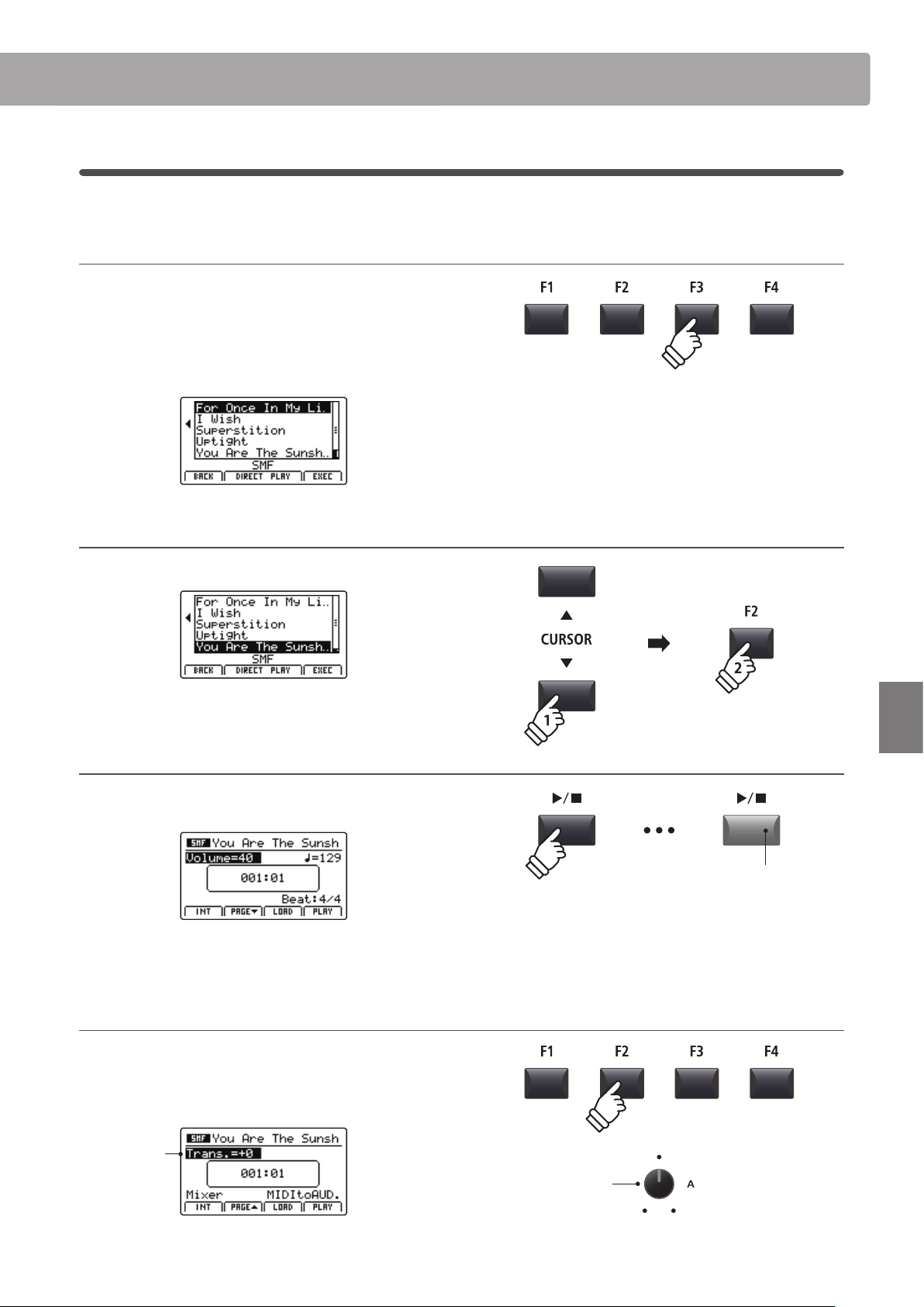
79
Recorder
Song Recorder (Internal memory)
9
SMF Direct Play
This function allows 16-track SMF les to be played directly from USB memory.
1. Selecting the Load SMF function
After preparing and connecting the USB memory:
Press the F3 function button (LOAD).
A listing of the SMF les stored in the root folder of the USB
device will be shown in the LCD display.
2. Selecting the SMF le to play
Press the CURSOR buttons to select the desired MIDI le.
Press the F2 or F3 function buttons (DIRECT PLAY).
3. Playing the selected SMF le
After selecting the Direct Play function, the player screen will be
shown in the LCD display.
For more information about playing the loaded MIDI le and using
the ‘Chain Play’ feature, please refer to page 71.
Changing the song transpose value
Press the F2 function button (PAGE) to show the second page
of playback functions.
Turn control knob A to change the song transpose value.
Song
transpose
* The Song Transpose value can be adjusted within the range of –12 ~ +12.
* Press the F1 function button (INT) to exit the SMF Direct Play function and
return to the internal song player screen.
Song
transpose
LED indicator ON:
Playback is in progress
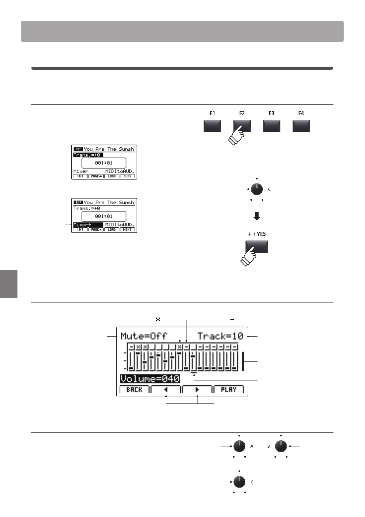
80
Recorder
Song Recorder (Internal memory)
SMF Mixer
The SMF Mixer screen allows the volume levels of all 16 tracks of the loaded SMF le to be adjusted or muted.
1. Selecting the SMF Mixer
After loading an SMF le:
Press the F2 function button (PAGE) to show the second page
of playback functions.
Turn control knob C to highlight the Mixer function.
Mixer function
highlighted
* The CURSOR buttons can also be used to move the selection cursor.
Press the +/YES button to select the Mixer function.
The SMF Mixer screen will be shown in the LCD display.
SMF Mixer screen
Track fader:
Visual representation
of each track’s volume.
Track number:
Select the track to adjust.
Track mute ON/OFF:
Play or mute the
selected track.
Track volume:
Adjust the volume of
the selected track.
Muted track:
Represented by
icon.
Move track selection cursor:
Select the track to adjust.
Track selection cursor:
Indicates the selected track.
Empty track:
Represented by
icon, track cannot be selected.
2. Selecting tracks, muting and adjusting volume
After selecting the Mixer function:
Turn control knob B to select the track for adjustment, and
control knob C to adjust the volume level.
Turn control knob A to Mute/Play the selected track.
* The F2 or F3 function buttons ( and ) can also be used to select tracks.
Mixer
function
Adjust
volume
Mute/Play
track
Select
track
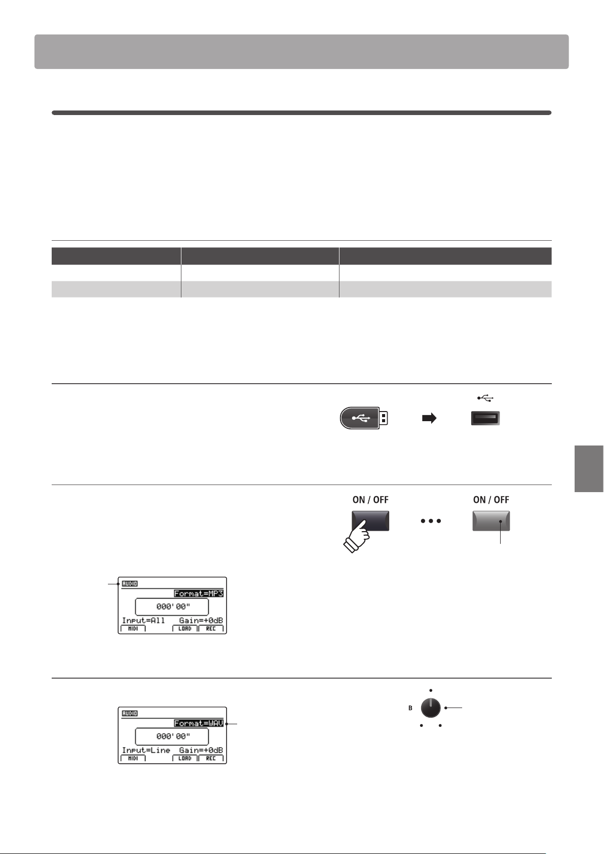
81
Recorder
Audio Record/Playback (USB memory)
1
Recording an audio le
The MP7SE is also capable of recording performances (including LINE IN input audio) as digital audio – saving
the data to a USB memory device in either MP3 or WAV format. This useful function allows professional quality
recordings to be produced directly on the instrument – without the need for additional sound equipment – then
emailed to band members, listened to away from the instrument, or edited and remixed further using an audio
workstation.
Audio Recorder format specications
Audio Format Specications Bitrate
MP3 44.1 kHz, 16 bit, Stereo 192 kbit/s (xed)
WAV 44.1 kHz, 16 bit, Stereo 1,411 kbit/s (uncompressed)
* MPEG Layer-3 audio coding technology licensed from Fraunhofer IIS and Thomson.
MP3 codec is Copyright (c) 1995-2007, SPIRIT
1. Connecting a USB memory device
Connect a USB memory device to the USB to Device port.
* USB devices should be formatted to use the ‘FAT’ or ‘FAT32’ lesystems.
The USB device will be scanned.
2. Turning the Recorder mode ON
Press the RECORDER section’s ON/OFF button to turn Recorder
mode ON.
The LED indicator for the RECORDER section’s ON/OFF button
will turn ON, and the Audio recorder screen will be shown in the
LCD display.
Audio
recorder
selected
Selecting the audio recorder le format
Turn control knob B to select the desired audio recorder format.
Audio
recorder
format
* MP3 audio les require less storage space than WAV audio les.
* A 1 GB USB memory device can store over 12 hours of MP3 audio data.
LED indicator ON:
Recorder mode is turned ON
Audio recorder
format
* If the MIDI recorder screen is shown, press the F1 function button (AUDIO)
to select the Audio recorder.
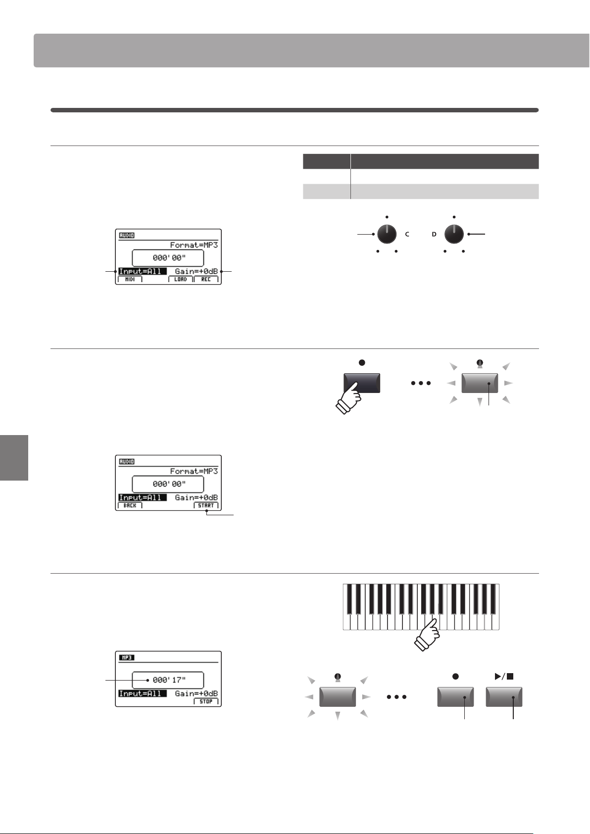
82
Recorder
Audio Record/Playback (USB memory)
Selecting the audio recorder input, adjusting gain level
Turn control knob C to select the desired audio recorder input.
Turn control knob D to adjust the gain level of the recorder.
Increasing the audio recorder gain level parameter may be useful
when recording quieter passages.
Audio
recorder
Gain level
Audio
recorder
input
* The gain level can be set within the range of –18 dB ~ +18 dB.
3. Starting the audio recorder (standby)
Press the recorder control button.
The LED indicator for the button will start to ash, to indicate
that the recorder is in standby mode.
* The F4 function button (REC) can also be used to engage standby mode.
* Depending on the USB memory device connected, there may be a brief
delay before standby mode is engaged.
Standby
mode
4. Starting the audio recorder (record)
Press a key on the keyboard.
The LED indicators for the and / buttons will turn ON,
the time counter shown in the centre of the LCD will begin to
increase, and recording will start.
Time
counter
* Recording can also be started by pressing the / button. This allows a
rest period or empty bar to be inserted at the beginning of the song.
* The metronome can be enabled before recording to assist with timing etc.
When enabled, a one bar count-in will be added before recording begins.
LED indicator ashing:
Recorder is in standby mode
Input Description
All Record the keyboard sound and the LINE IN sound.
Line Record the LINE IN sound only.
Recorder
input
Recorder
gain level
LED indicators ON:
Recording is in progress
1
Recording an audio le (cont.)
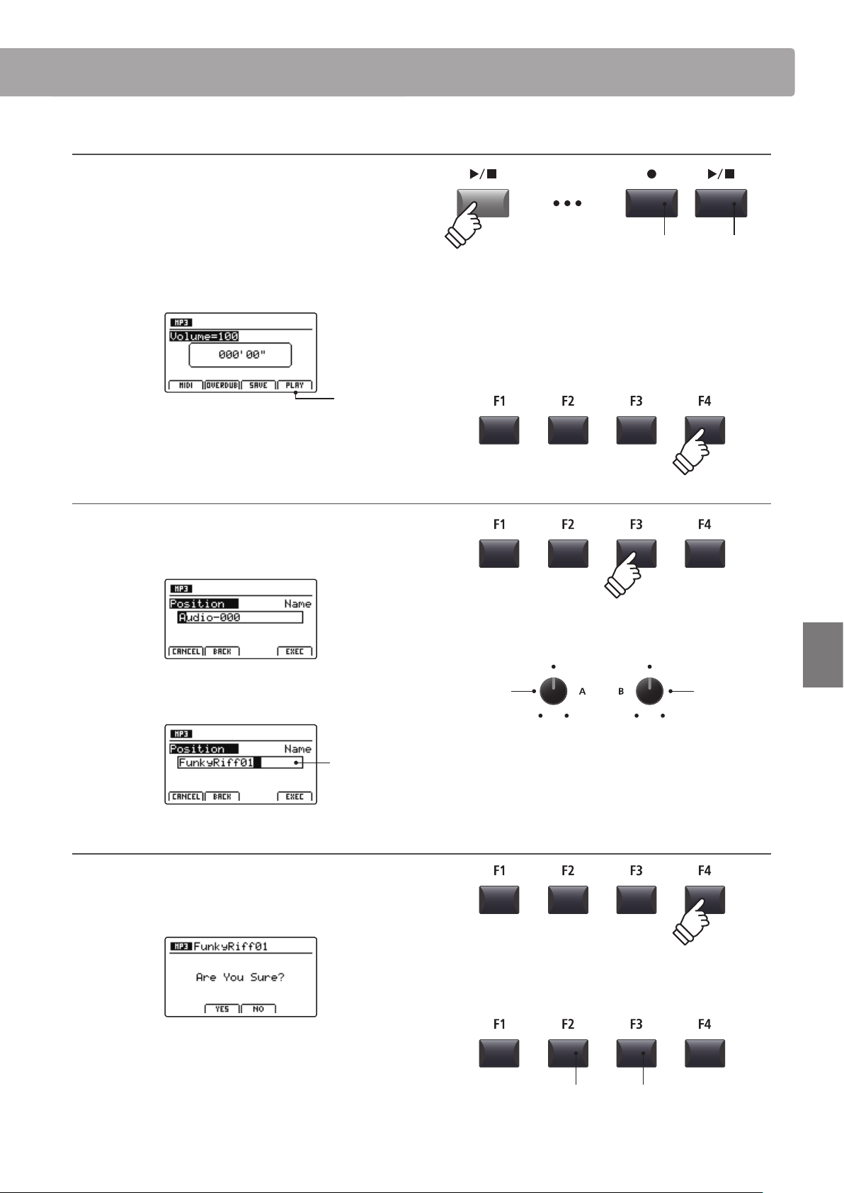
83
Recorder
Audio Record/Playback (USB memory)
5. Stopping the audio recorder, auditioning the recording
Press the / recorder control button.
The LED indicators for the and / buttons will turn OFF, and
recording will stop.
* The F4 function button (STOP) can also be used to stop recording.
After a brief pause, the Audio player screen will be shown in the
LCD display.
Audition
recording
Press the F4 function button (PLAY) to audition the recording
before saving.
6. Selecting the save function, entering the audio le name
Press the F3 function button (SAVE).
The save audio screen will be shown in the LCD display.
Turn control knobs A and B to move the cursor position and
select the characters for the audio le name.
Audio
le name
7. Saving the audio le
Press the F4 function button (EXEC).
The save audio conrmation screen will be shown in the LCD
display.
Press the F2 button (YES) to conrm the save audio operation,
or the F3 button (NO) to return to the previous screen.
* The +/YES and –/NO buttons can also be used to conrm or cancel the
save operation.
* To prevent data loss, avoid turning the power OFF while the MP7SE is
saving les to USB memory.
LED indicators OFF:
Recording has stopped
Move cursor
position
Select
character
* Saved audio les are limited to a maximum name length of 18 characters.
* The saved audio le will be stored in the root folder of the USB memory
device. It is not possible to store the le in a dierent folder.
F3 button:
NO: Cancel
F2 button:
YES: Conrm
* Press the and / recorder control buttons simultaneously to erase the
recorded audio le from memory.
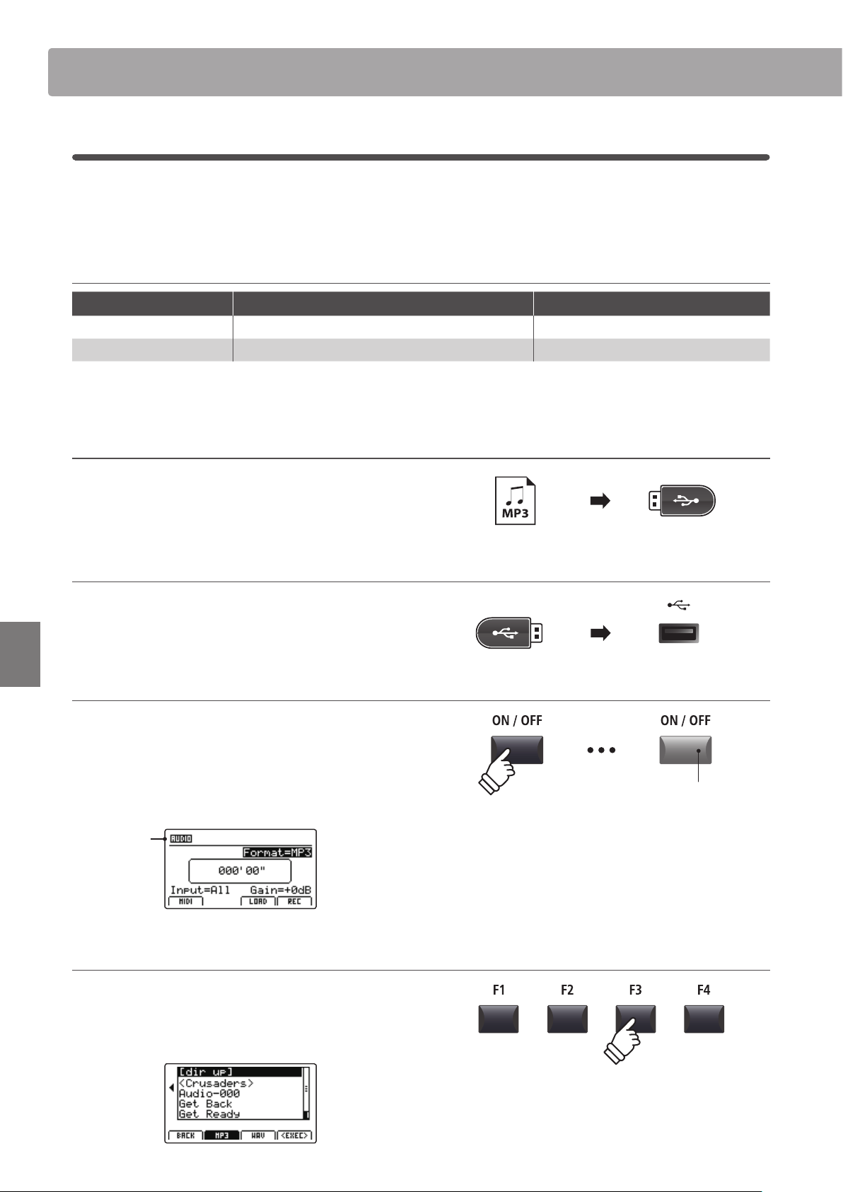
84
Recorder
Audio Record/Playback (USB memory)
2
Playing an audio le
The MP7SE is also capable of playing MP3 and WAV audio les stored on a USB memory device. This function allows
performing musicians to play along with professional backing tracks, or conveniently learn the chords or melody
for a new piece.
Audio Player supported format specications
Audio Format Specications Bitrate
MP3 32 kHz/44.1 kHz/48 kHz, Mono/Stereo 8-320 kbit/s (xed & variable)
WAV 32 kHz/44.1 kHz/48 kHz, Mono/Stereo, 8 bit/16 bit -
* MPEG Layer-3 audio coding technology licensed from Fraunhofer IIS and
Thomson. MP3 codec is Copyright (c) 1995-2007, SPIRIT
Preparing the USB memory device
Prepare a selection of MP3 or WAV audio les, copying the data
to a USB memory device.
* USB devices should be formatted to use the ‘FAT’ or ‘FAT32’ lesystems.
1. Connecting a USB memory device
Connect the USB memory device to the USB to Device port.
The USB device will be scanned.
2. Turning the Recorder mode ON
Press the RECORDER section’s ON/OFF button to turn Recorder
mode ON.
The LED indicator for the RECORDER section’s ON/OFF button
will turn ON, and the Audio recorder screen will be shown in the
LCD display.
Audio
recorder
selected
3. Selecting the Load Audio function
Press the F3 function button (LOAD).
A listing of the MP3 les stored in the root folder of the USB
device will be shown in the LCD display.
LED indicator ON:
Recorder mode is turned ON
* If the MIDI recorder screen is shown, press the F1 function button (AUDIO)
to select the Audio recorder.
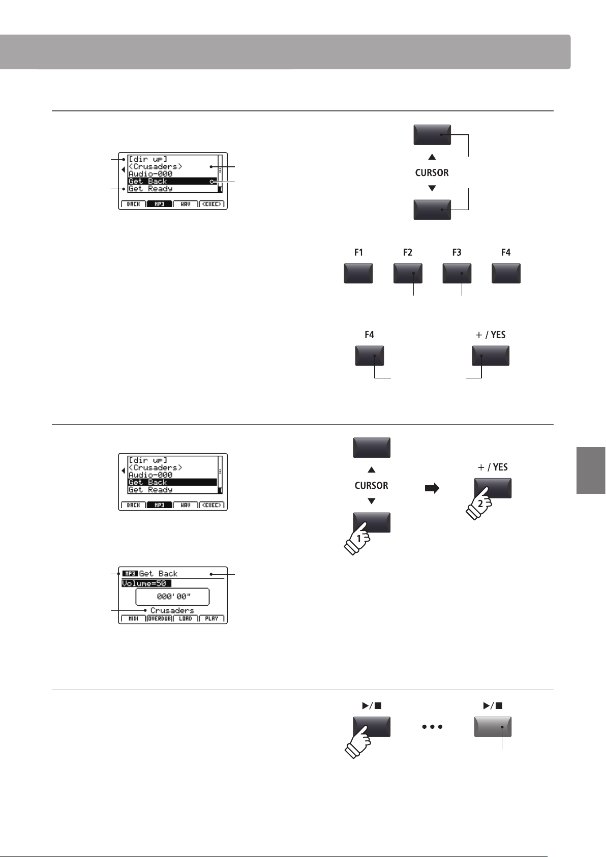
85
Recorder
Audio Record/Playback (USB memory)
USB device le/folder listing screen
The MP7SE’s le/folder listing screen lists relevant les and
folders stored in the root of the USB device.
Previous
folder
Folder
File
Selection
cursor
Press the CURSOR buttons to move the selection cursor.
* Control knob A can also be used to move the selection cursor.
Press the F3 or F2 function buttons to alternate between
showing WAV or MP3 format audio les.
* By default, MP3 les will be shown.
Press the F4 function button (EXEC) or +/YES button to select
the le or enter the selected folder.
4. Selecting the audio le to load
Press the CURSOR buttons to select the desired audio le.
Press the F4 function button (EXEC) or +/YES button.
The audio player screen will be shown in the LCD display.
MP3 audio
Track name
Artist
* If available, the audio le’s metadata (ID3 tags etc.) will also be shown.
5. Starting audio le playback
Press the / recorder control button.
The LED indicator for the / button will turn ON, and the
selected song will start to play.
* The F4 function button (PLAY) can also be used to start song playback.
Move
selection
cursor
or
Select le/folder
F3 button:
Show WAV les
F2 button:
Show MP3 les
LED indicator ON:
Playback is in progress
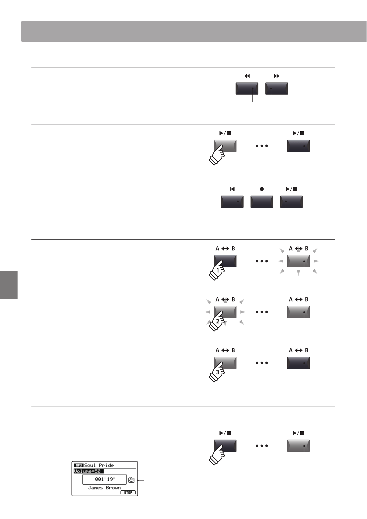
86
Recorder
Audio Record/Playback (USB memory)
Moving the playback position (seek)
Press the or recorder control buttons to rewind or fast-
forward the playing position of the audio le .
* The playback position can be moved both before and during playback.
6. Stopping audio le playback
While an audio le is playing:
Press the / recorder control
button.
The LED indicator for the / button will turn OFF, and audio le
playback will stop.
Press the /
button again to continue playback from the stopped
position, or the
button to reset the playback position to the
beginning of the audio le.
* The F4 function button (STOP) can also be used to reset audio playback.
A-B Repeat function
The A-B Repeat function allows one section of an audio le to be
repeated continuously (looped). This function can be activated
both before and during audio le playback.
Press the A B recorder control button once to set the start
point of the loop.
The LED indicator for the A B button will start to ash.
Press the A B button again to set the end point of the loop.
The LED indicator for the A B button will turn ON and the
specied section will repeat continuously.
Press the A B button once again to cancel the loop.
The LED indicator for the A B button will turn OFF and normal
playback will resume.
Chain Play mode
Chain Play mode allows all audio les stored in a folder to be played continuously, in sequence.
Press and hold the / recorder control button.
The Chain Play icon will be shown in the LCD display, and the
audio les will start to play continuously, in sequence.
Chain Play
activated
LED indicator ON:
Playback is in progress
button:
Fast-Forward
button:
Rewind
button:
Reset position
/ button:
Resume playback
LED indicator OFF:
Playback has stopped
LED indicator ashing:
Start point of the loop set
LED indicator ON:
End point of the loop set, loop activated
LED indicator OFF:
Loop deactivated, normal playback resumes
hold
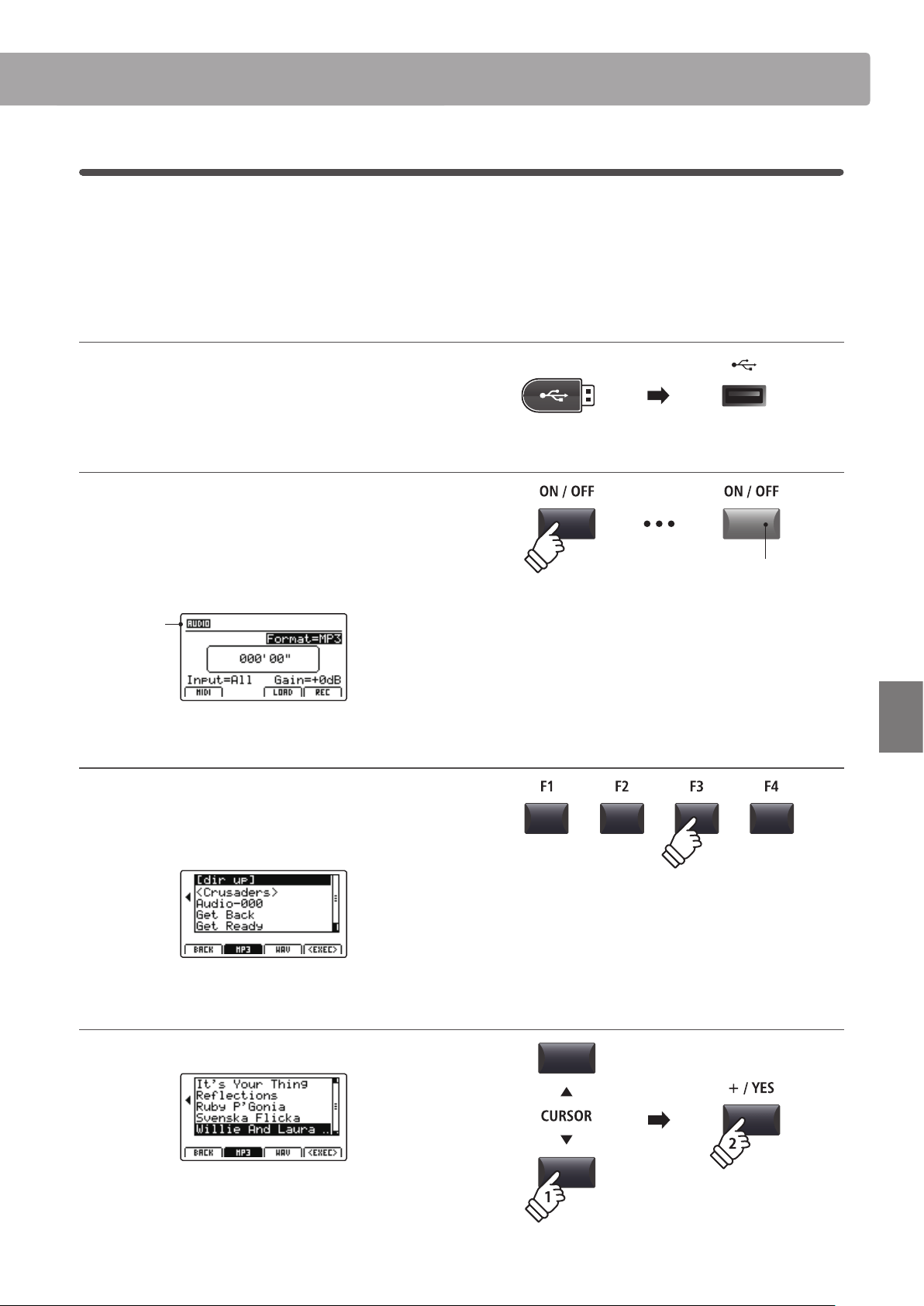
87
Recorder
Audio Record/Playback (USB memory)
3
Overdubbing an audio le
The overdub function adds supplementary recording(s) to an existing audio le, facilitating simple multi-track
recordings to be produced directly on the instrument.
Each overdub is recorded to a temporary le (i.e. the original audio le is not modied), allowing an unlimited
number of overdubs that to be made before eventually saving the nal recording.
1. Connecting a USB memory device
Connect the USB memory device to the USB to Device port.
The USB device will be scanned.
2. Turning the Recorder mode ON
Press the RECORDER section’s ON/OFF button to turn Recorder
mode ON.
The LED indicator for the RECORDER section’s ON/OFF button
will turn ON, and the Audio recorder screen will be shown in the
LCD display.
Audio
recorder
selected
3. Selecting the Load Audio function
Press the F3 function button (LOAD).
A listing of the MP3 les stored in the root folder of the USB
device will be shown in the LCD display.
4. Selecting the audio le to load
Press the CURSOR buttons to select the desired audio le.
Press the F4 function button (EXEC) or +/YES button.
The audio player screen will be shown in the LCD display.
LED indicator ON:
Recorder mode is turned ON
* If the MIDI recorder screen is shown, press the F1 function button (AUDIO)
to select the Audio recorder.
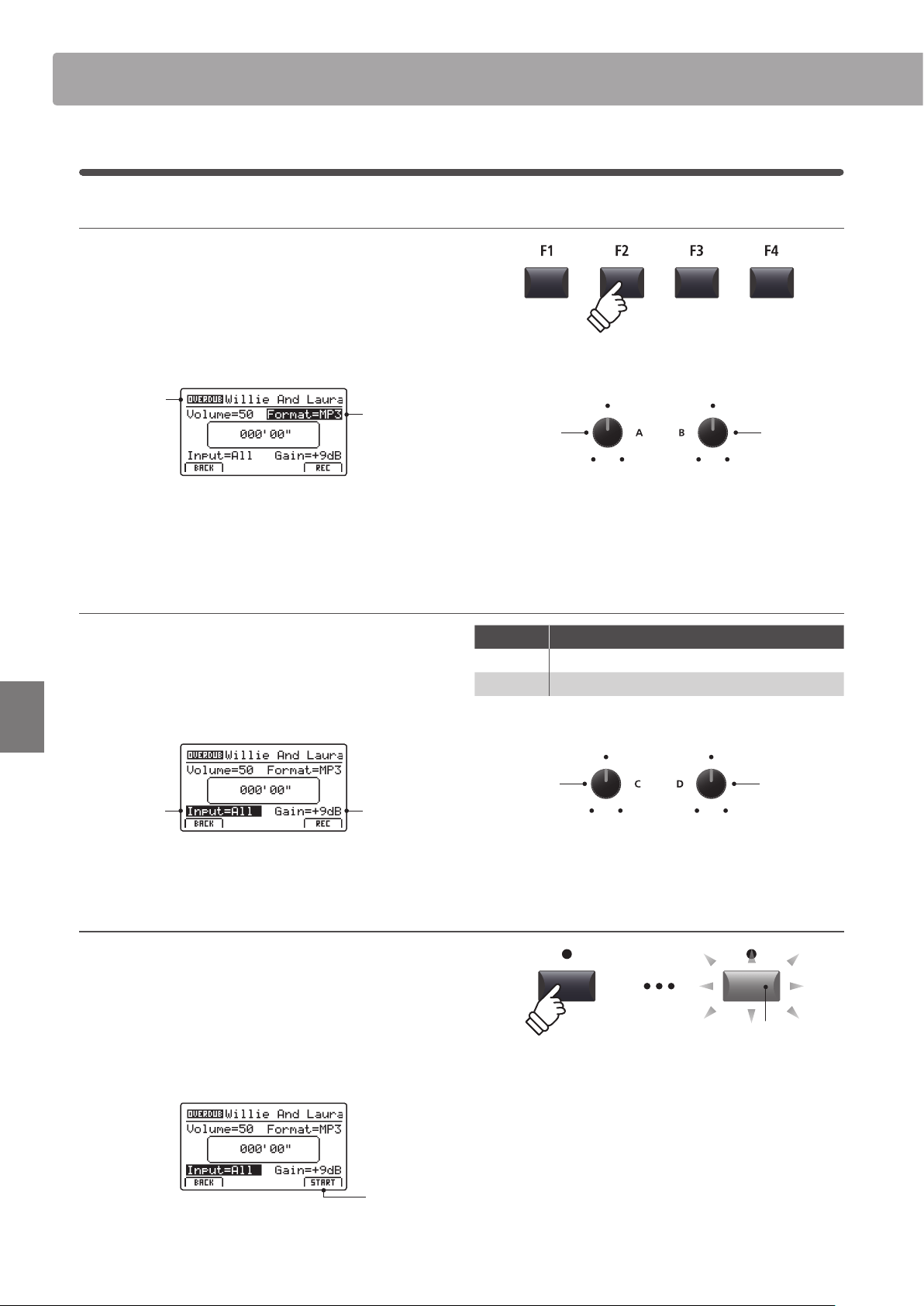
88
Recorder
Audio Record/Playback (USB memory)
5. Selecting the overdub function and le format
Press the F2 function button (OVERDUB).
The overdub le format selection screen will be shown in the
LCD display.
Turn control knob B to select the desired overdub le format,
and control knob A to adjust the volume of the source audio.
Audio
recorder
format
Overdub
selected
* MP3 audio les require less storage space than WAV audio les.
* A 1 GB USB memory device can store over 12 hours of MP3 audio data.
Selecting the audio recorder input, adjusting gain level
Turn control knob C to select the desired audio recorder input.
Turn control knob D to adjust the gain level of the overdub.
Increasing the audio recorder gain level parameter may be useful
when recording quieter passages.
Overdub
Gain level
Audio
recorder
input
* The gain level can be set within the range of –18 dB ~ +18 dB.
6. Starting the overdub (standby)
Press the recorder control button.
The LED indicator for the button will start to ash, to indicate
that the recorder is in standby mode.
* The F4 function button (REC) can also be used to engage standby mode.
* Depending on the USB memory device connected, there may be a brief
delay before standby mode is engaged.
Standby
mode
Input Description
All Record the keyboard sound and the LINE IN sound.
Line Record the LINE IN sound only.
Recorder
input
Recorder
gain level
LED indicator ashing:
Recorder is in standby mode
Source audio
volume
Overdub le
format
3
Overdubbing an audio le (cont.)
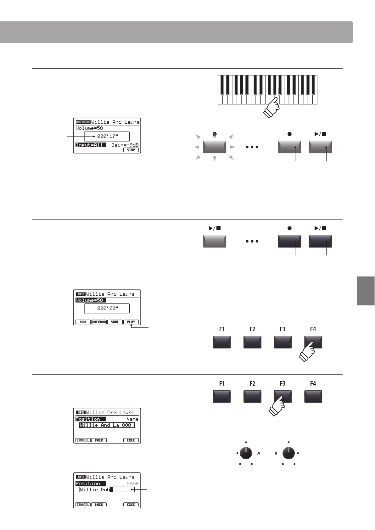
89
Recorder
Audio Record/Playback (USB memory)
7. Starting the overdub (record)
Press a key on the keyboard.
The LED indicators for the and / buttons will turn ON,
the time counter shown in the centre of the LCD will being to
increase, and overdubbing will start.
Time
counter
* Overdubbing can also be started by pressing the / button. This allows
a rest period or empty bar to be inserted at the beginning of the song.
* The metronome can be enabled before overdubbing to assist with timing
etc. When enabled, a one bar count-in will be added before overdubbing
begins.
8. Stopping and auditioning the overdub
Press the / recorder control button.
The LED indicators for the and / buttons will turn OFF, and
overdubbing will stop.
* The F4 function button (STOP) can also be used to stop overdubbing.
After a brief pause, the Audio player screen will be shown in the
LCD display.
Audition
overdub
Press the F4 function button (PLAY) to audition the overdub
before saving.
9. Selecting the save function, entering the audio le name
Press the F3 function button (SAVE).
The save audio screen will be shown in the LCD display.
Turn control knobs A and B to move the cursor position and
select the characters for the audio le name.
Audio
le name
LED indicators ON:
Overdubbing is in progress
Move cursor
position
Select
character
* Saved audio les are limited to a maximum name length of 18 characters.
* The saved audio le will be stored in the root folder of the USB memory
device. It is not possible to store the le in a dierent folder.
LED indicators OFF:
Recording has stopped
* Press the and / recorder control buttons simultaneously to erase the
overdubbed audio le from memory.
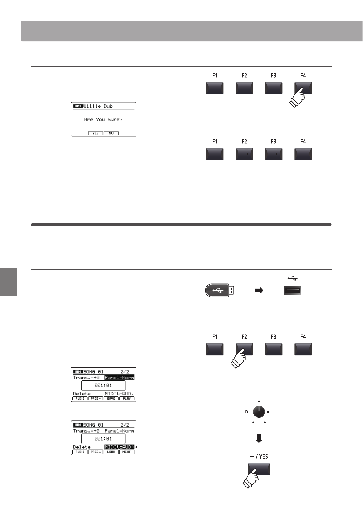
90
Recorder
Audio Record/Playback (USB memory)
10. Saving the dubbed le
Press the F4 function button (EXEC).
The save audio conrmation screen will be shown in the LCD
display.
Press the F2 button (YES) to conrm the save audio operation,
or the F3 button (NO) to return to the previous screen.
* The +/YES and –/NO buttons can also be used to conrm or cancel the
save operation.
* To prevent data loss, avoid turning the power OFF while the MP7SE is
saving les to USB memory.
4
MIDI to Audio
This function allows recorder songs stored in internal memory to be played back and saved (converted) as an audio
le to a USB device in either MP3 or WAV format.
1. Connecting a USB memory device
Connect the USB memory device to the USB to Device port.
* USB devices should be formatted to use the ‘FAT’ or ‘FAT32’ lesystems.
The USB device will be scanned.
2. Selecting the MIDI to Audio function
After selecting the MIDI recorder and recording a song:
Press the F2 function button (PAGE) to show the additional
MIDI recorder functions.
Turn control knob D to highlight the MIDI to Audio function.
MIDI to AUDIO
highlighted
* The CURSOR buttons can also be used to move the selection cursor.
Press the +/YES button to select the MIDI to Audio function.
The MIDI to Audio screen will be shown in the LCD display.
F3 button:
NO: Cancel
F2 button:
YES: Conrm
MIDI to AUDIO
function
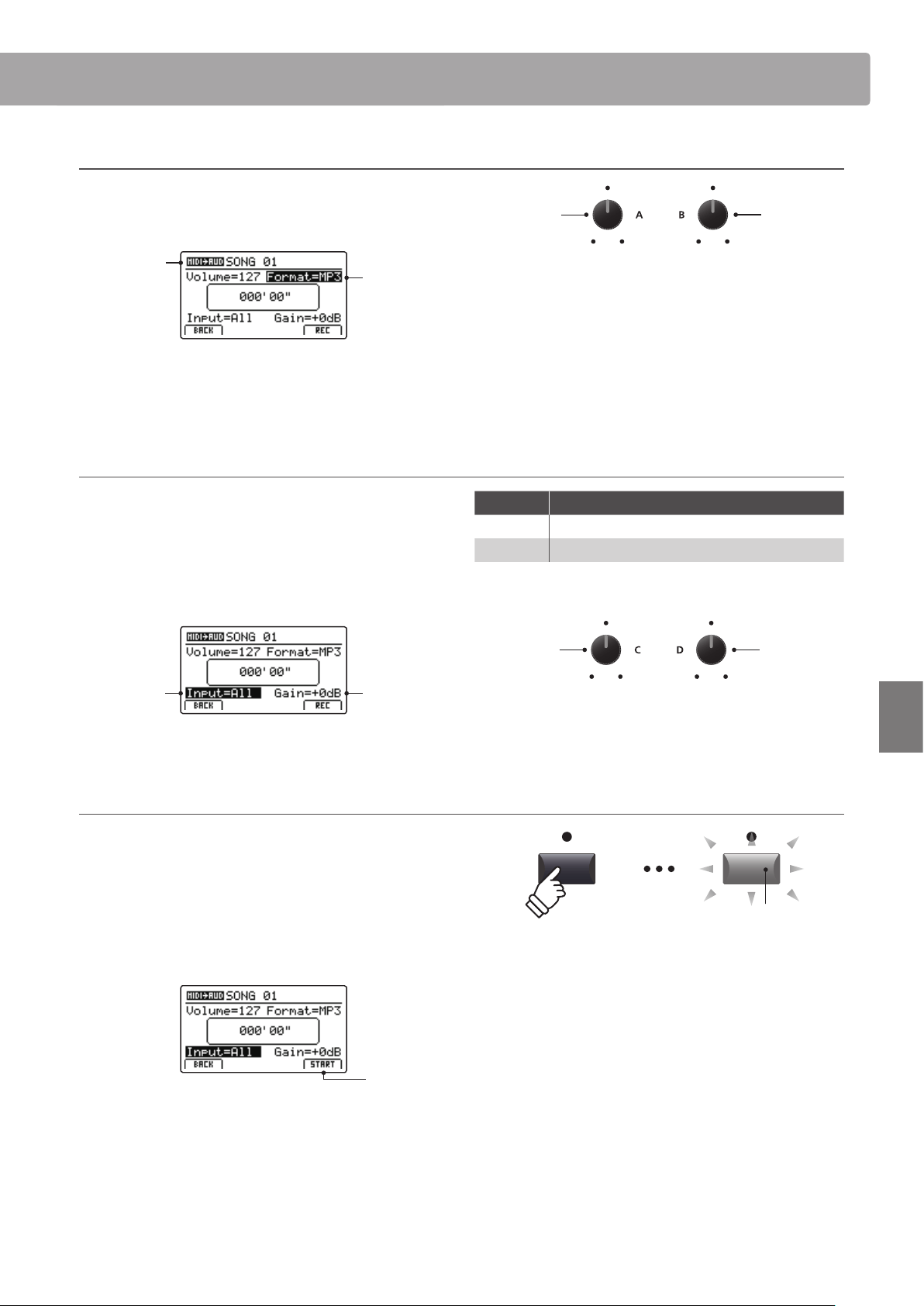
91
Recorder
Audio Record/Playback (USB memory)
3. Selecting the MIDI to Audio le format
Turn control knob B to select the desired MIDI to Audio le
format, and control knob A to adjust the volume of the song
playback.
Audio
recorder
format
MIDI to Audio
selected
* MP3 audio les require less storage space than WAV audio les.
* A 1 GB USB memory device can store over 12 hours of MP3 audio data.
Selecting the audio recorder input, adjusting gain level
Turn control knob C to select the desired audio recorder input.
Turn control knob D to adjust the gain level of the MIDI to Audio
conversion/recording.
Increasing the audio recorder gain level parameter may be useful
when recording quieter passages.
MIDI to Audio
Gain level
Audio
recorder
input
* The gain level can be set within the range of –18 dB ~ +18 dB.
4. Starting the conversion (standby)
Press the recorder control button.
The LED indicator for the button will start to ash, to indicate
that the recorder is in standby mode.
* The F4 function button (REC) can also be used to engage standby mode.
* Depending on the USB memory device connected, there may be a brief
delay before standby mode is engaged.
Standby
mode
Input Description
All Record the keyboard sound and the LINE IN sound.
Line Record the LINE IN sound only.
Recorder
input
MIDI to Audio
gain level
Song playback
volume
MIDI to Audio
le format
LED indicator ashing:
Recorder is in standby mode
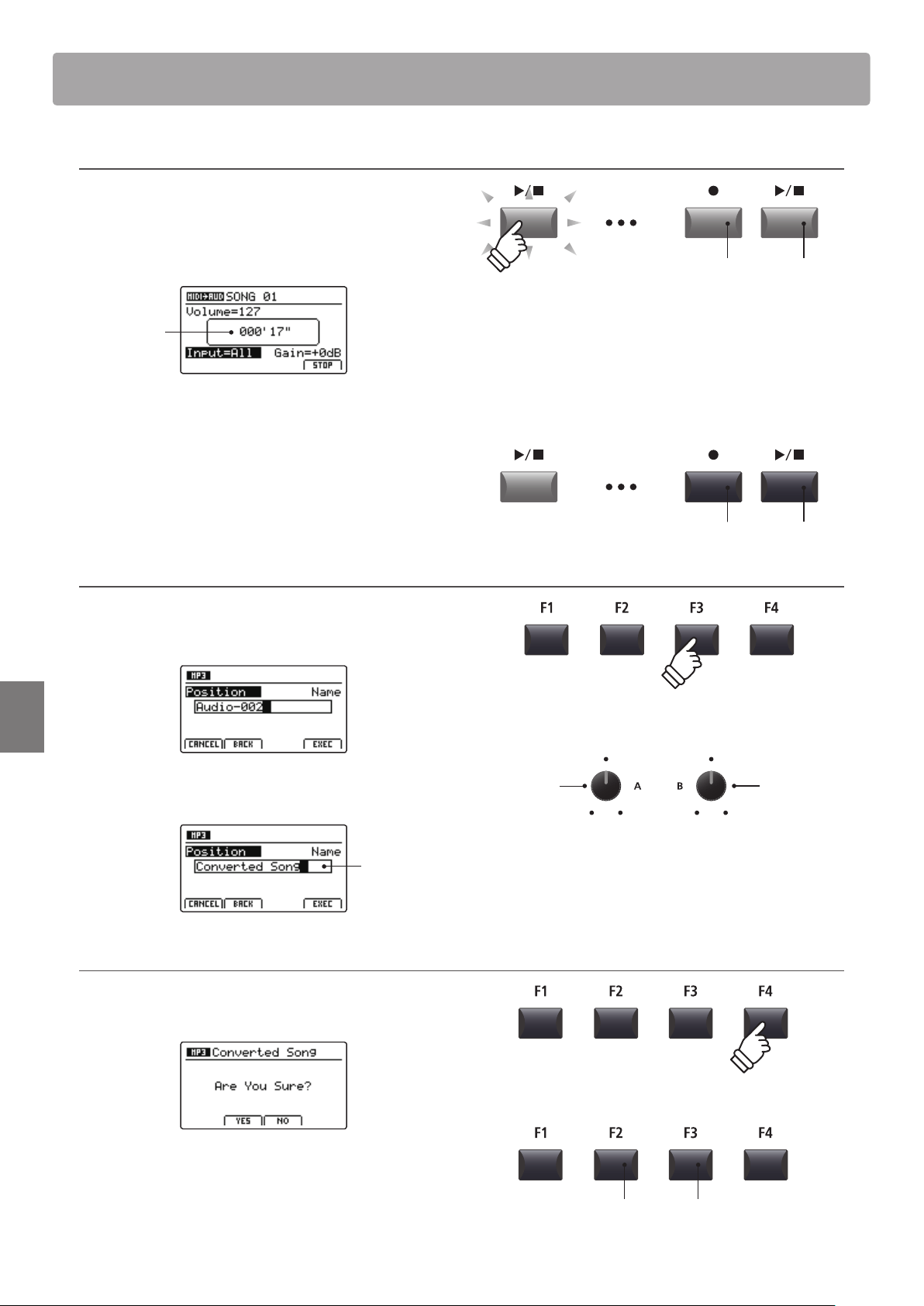
92
Recorder
Audio Record/Playback (USB memory)
5. Starting the conversion (record)
Press the / recorder control button.
The LED indicators for the and / buttons will turn ON,
the time counter shown in the centre of the LCD will begin to
increase, and the conversion will start.
Time
counter
Conversion will stop automatically when the end of the recorder
song is reached.
* The / button or F4 function button (STOP) can also be used to stop the
conversion before the end of the song.
The LED indicators for the and / buttons will turn OFF, and
the conversion will stop.
6. Selecting the save function, entering the audio le name
Press the F3 function button (SAVE).
The save audio screen will be shown in the LCD display.
Turn control knobs A and B to move the cursor position and
select the characters for the audio le name.
Audio
le name
7. Saving the converted audio le
Press the F4 function button (EXEC).
The save conrmation screen will be shown in the LCD display.
Press the F2 button (YES) to conrm the save audio operation,
or the F3 button (NO) to return to the previous screen.
* The +/YES and –/NO buttons can also be used to conrm or cancel the
save operation.
* To prevent data loss, avoid turning the power OFF while the MP7SE is
saving les to USB memory.
LED indicators ON:
Recording is in progress
Move cursor
position
Select
character
* Saved audio les are limited to a maximum name length of 18 characters.
* The saved audio le will be stored in the root folder of the USB memory
device. It is not possible to store the le in a dierent folder.
LED indicators OFF:
Recording has stopped
F3 button:
NO: Cancel
F2 button:
YES: Conrm
* Conversion can also be started by pressing the F4 function button (START).
* Notes played on the keyboard will also be recorded to the audio le..
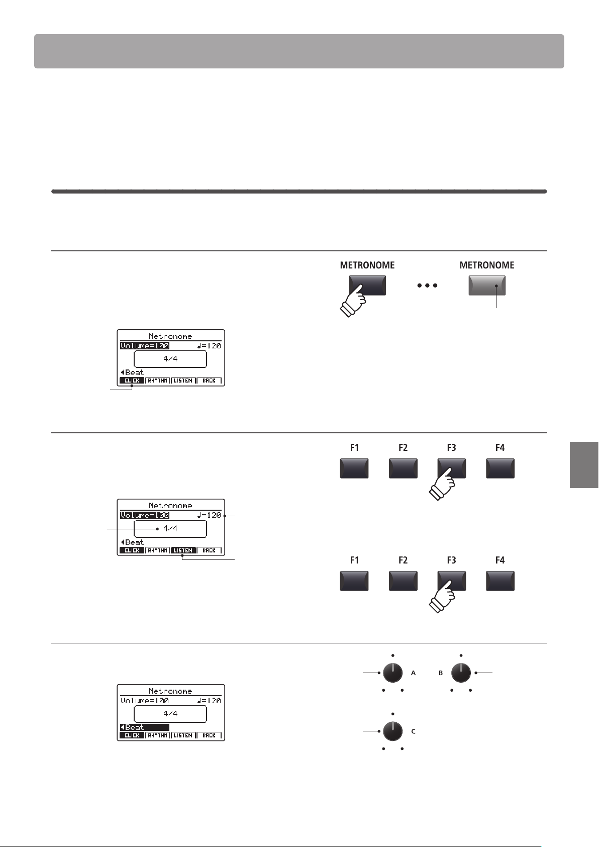
93
Recorder
Metronome
The Metronome function provides a steady beat to aid practicing the piano at a consistent tempo. In addition
to regular metronome beats in various time signatures, the MP7SE also features a selection of drum rhythms to
accompany most playing styles and musical genres.
1
Click mode
In Click mode, the metronome function provides a simple click track in a number of dierent time signatures.
Activating the metronome function
Press the METRONOME button.
The LED indicator for the METRONOME button will turn ON
to indicate that the metronome function is in use, and the
Metronome screen will be shown in the LCD display.
Click mode
selected
Starting and Stopping the metronome
Press the F3 function button (LISTEN)
The LISTEN icon will become highlighted and the metronome
will start counting a 4/4 beat at 120 bpm (beats per minute).
Tempo
Time
signature
Metronome
is counting
Press the F3 function button again to stop the metronome.
Adjusting the Metronome volume, tempo, and time signature (beat)
Turn control knobs A and B to adjust the metronome volume
and tempo, and knob C to change the time signature (beat).
* The metronome tempo can be adjusted within the range of 30-300 bpm
(60-600 bpm for eighth note time signatures).
* There are ten dierent types of beat/time signature available:
1/4, 2/4, 3/4, 4/4, 5/4, 3/8, 6/8, 7/8, 9/8, and 12/8.
Time
signature
Volume
Tempo
* Preferred metronome settings can be saved to a SETUP or POWERON
memory for immediate recall.
LED indicator ON:
Metronome is turned ON
* The metronome will be set to Click mode by default.
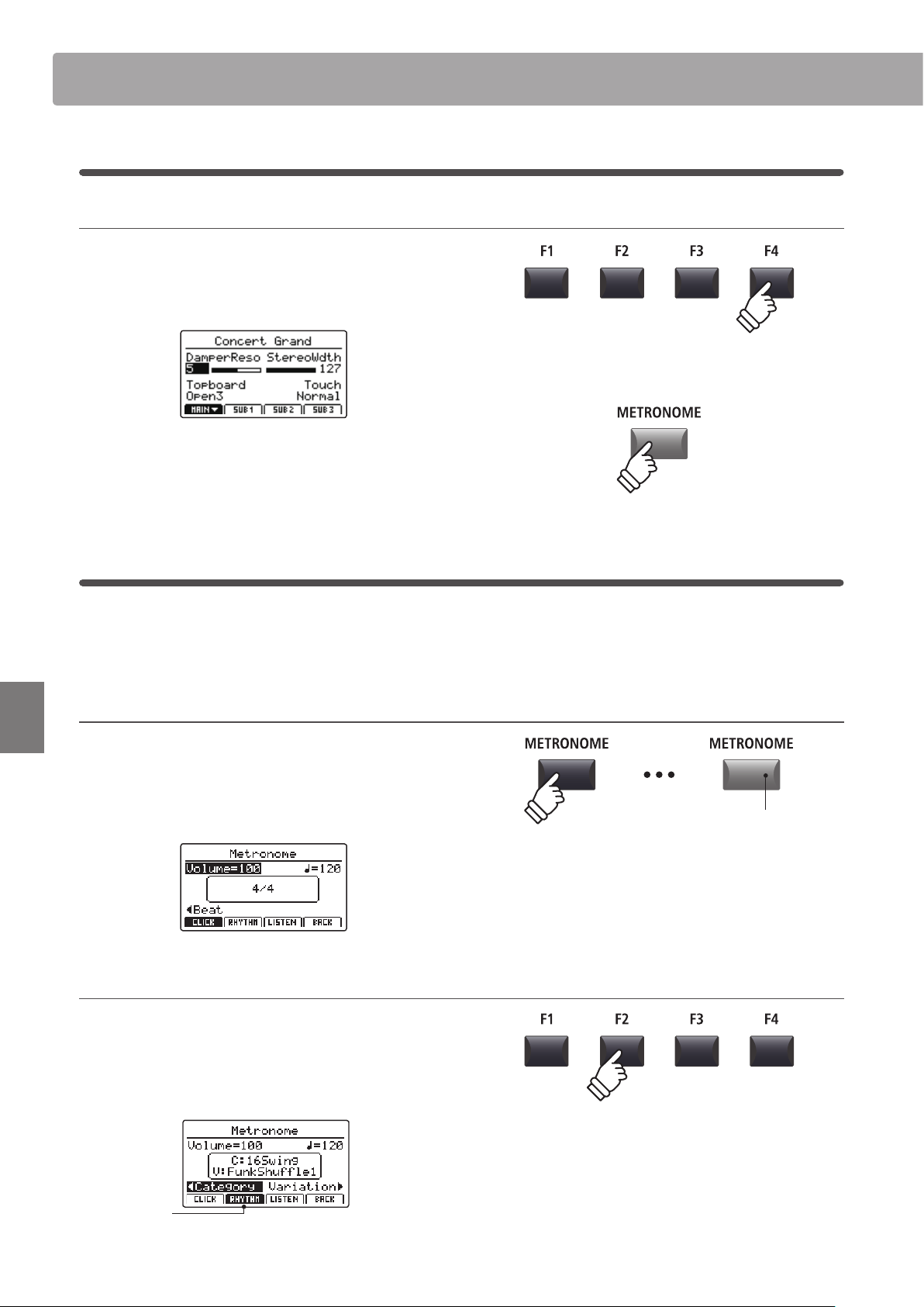
94
Recorder
Metronome
Returning to the previous screen (BACK function)
While the metronome is counting:
Press the F4 function button (BACK) to return to the previous
screen without stopping or deactivating the metronome.
Press and hold the METRONOME button again to show the
Metronome screen in the LCD display.
2
Rhythm mode
In Rhythm mode, the metronome function provides a more musically inspiring drum track. There are 100 dierent
drum patterns available, grouped into 13 categories.
* For a full listing of available drum patterns, please refer to page 96.
Activating the metronome function
Press the METRONOME button.
The LED indicator for the METRONOME button will turn ON
to indicate that the metronome function is in use, and the
Metronome screen will be shown in the LCD display.
Selecting Rhythm mode
Press the F2 function button (RHYTHM)
The RHYTHM icon will become highlighted, and the currently
selected drum rhythm category and variation will be shown in
the LCD display.
Rhythm mode
selected
hold
LED indicator ON:
Metronome is turned ON
* The metronome will be set to Click mode by default.
1
Click mode (cont.)
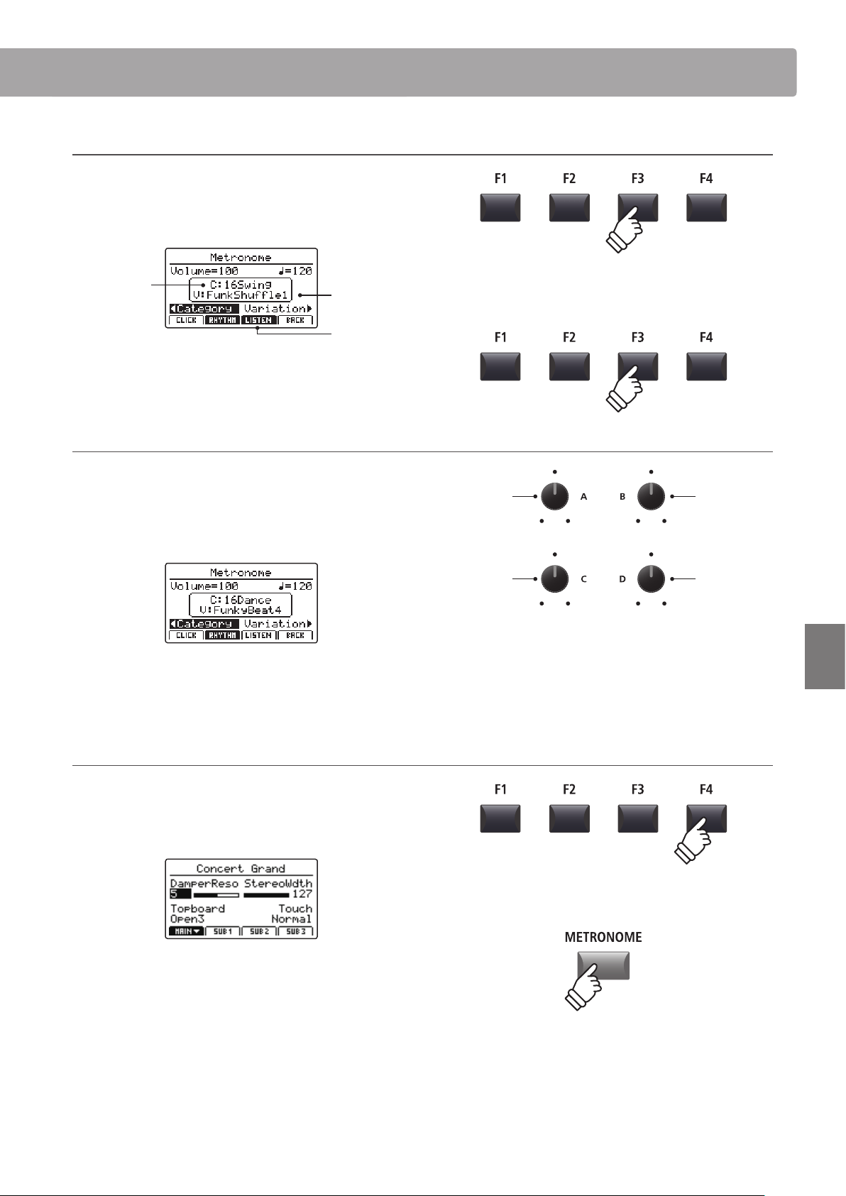
95
Recorder
Metronome
Starting and Stopping the drum rhythm
Press the F3 function button (LISTEN)
The LISTEN icon will become highlighted and the currently
selected drum rhythm category and variation will start to play.
Variation
Category
Rhythm is
playing
Press the F3 function button again to stop the drum rhythm.
Adjusting the drum rhythm volume, tempo, category, and variation
Turn control knobs A and B to adjust the drum rhythm volume
and tempo.
Turn control knobs C and D to select the drum rhythm category
and variation.
* The metronome tempo can be adjusted within the range of 30-300 bpm.
* For a full listing of available drum patterns, please refer to page 96.
Returning to the previous screen (BACK function)
While the drum rhythm is playing:
Press the F4 function button (BACK) to return to the previous
screen without stopping or deactivating the metronome.
Press and hold the METRONOME button again to show the
Metronome screen in the LCD display.
* Preferred drum rhythm settings can be saved to a SETUP or POWERON
memory for immediate recall.
Category
Volume
Variation
Tempo
hold

96
Recorder
Metronome
Drum rhythm categories and variations
16 Swing
1 Funk Shue 1
2 Funk Shue 2
3 Hip Hop 1
4 Hip Hop 2
5 Hip Hop 3
6 Hip Hop 4
7 16 Shue 1
8 16 Shue 2
9 16 Shue 3
16 Funk
10 Funky Beat 1
11 Funky Beat 2
12 Funky Beat 3
13 Funk 1
14 Funk 2
15 Funk 3
16 Straight
16 Jazz Funk
17 16 Beat 1
18 16 Beat 2
19 16 Beat 3
20 16 Beat 4
21 Ride Beat 4
22 Rim Beat
23 Roll Beat
24 Light Ride 1
25 Dixie Rock
16 Latin
26 Surdo Samba
27 Latin Groove
28 Light Samba
29 Songo
30 Samba
31 Merenge
16 Dance
32 Funky Beat 4
33 16 Beat 5
34 Disco 1
35 Disco 2
36 Techno 1
37 Techno 2
38 Techno 3
39 Heavy Techno
16 Ballad
40 Ballad 1
41 Ballad 2
42
Ballad 3
43 Ballad 4
44 Ballad 5
45 Light Ride 2
46 Electro Pop 1
47 Electro Pop 2
48 16 Shue 4
8 Ballad
49 Slow Jam
50 50’s Triplet
51 R&B Triplet
8 Straight
52 8 Beat 1
53 8 Beat 2
54 Smooth Beat
55 Pop 1
56 Pop 2
57 Ride Beat 1
58 Ride Beat 2
59 Ride Beat 3
60 Slip Beat
8 Rock
61 Jazz Rock
62 8 Beat 3
63 Rock Beat 1
64 Rock Beat 2
65 Rock Beat 3
66 Rock Beat 4
67 Blues/Rock
68 Heavy Beat
69 Hard Rock
70 Surf Rock
71 R&B
8 Swing
72 Motown 1
73 Fast Shue
74 Motown 2
75 Country 2 Beat
Triplet
76 Triplet Rock 1
77 Triplet Rock 2
78 Bembe
79 Rock Shue 1
80 Rock Shue 2
81 Boogie
82 Triplet 1
83 Triplet 2
84 Reggae
85 Gospel Ballad
86 Waltz
Jazz
87 H.H. Swing
88 Ride Swing
89 Fast 4 Beat
90 Afro Cuban
91 Jazz Waltz 1
92 Jazz Waltz 2
93 5/4 Swing
8 Latin
94 H.H. Bossa
95 Ride Bossa
96 Beguine
97 Mambo
98 Cha Cha
99 Tango
100 Habanera
2
Rhythm mode (cont.)
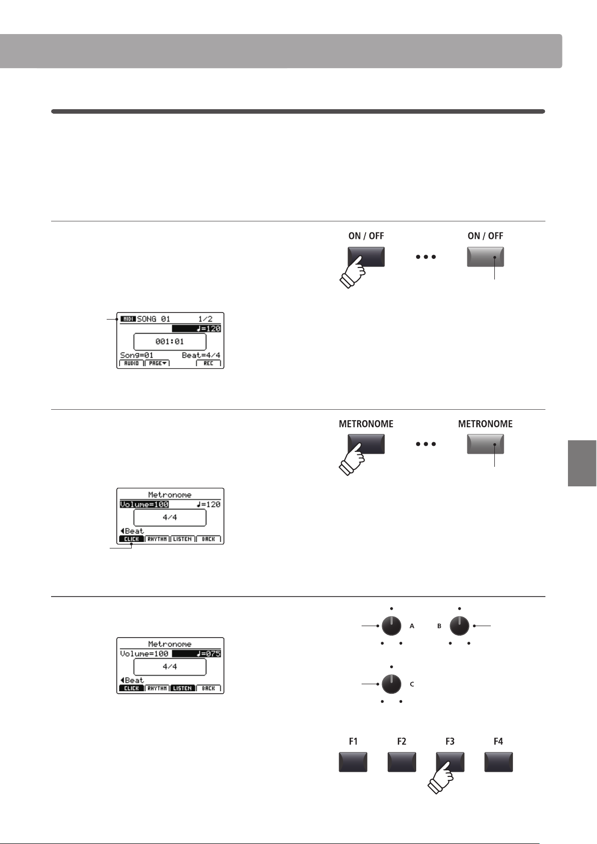
97
Recorder
Metronome
3
Recording with the metronome
Recording with the metronome is a convenient way to maintain consistent timing and rhythm while playing. This is
especially important when integrating recordings into a sequencer or DAW.
The explanation below uses the internal song recorder as an example, however the procedure for recording with
the metronome to an MP3/WAV audio le is identical.
1. Turning the Recorder mode ON
Press the RECORDER section’s ON/OFF button to turn Recorder
mode ON.
The LED indicator for the RECORDER section’s ON/OFF button
will turn ON, and the MIDI recorder screen will be shown in the
LCD display.
MIDI
recorder
selected
2. Activating the metronome function
Press the METRONOME button.
The LED indicator for the METRONOME button will turn ON
to indicate that the metronome function is in use, and the
Metronome screen will be shown in the LCD display.
Click mode
selected
3. Adjusting the Metronome volume, tempo, and time signature (beat)
Turn control knobs A and B to adjust the metronome volume
and tempo, and knob C to change the time signature (beat).
Press the F3 function button (LISTEN) to listen to the current
metronome settings.
* The metronome tempo can be adjusted within the range of 30-300 bpm
(60-600 bpm for eighth note rhythms).
* There are ten dierent types of beat/time signature available:
1/4, 2/4, 3/4, 4/4, 5/4, 3/8, 6/8, 7/8, 9/8, and 12/8.
* Preferred metronome settings can be saved to a SETUP or POWERON
memory for immediate recall.
LED indicator ON:
Recorder mode is turned ON
LED indicator ON:
Metronome is turned ON
Time
signature
Volume
Tempo
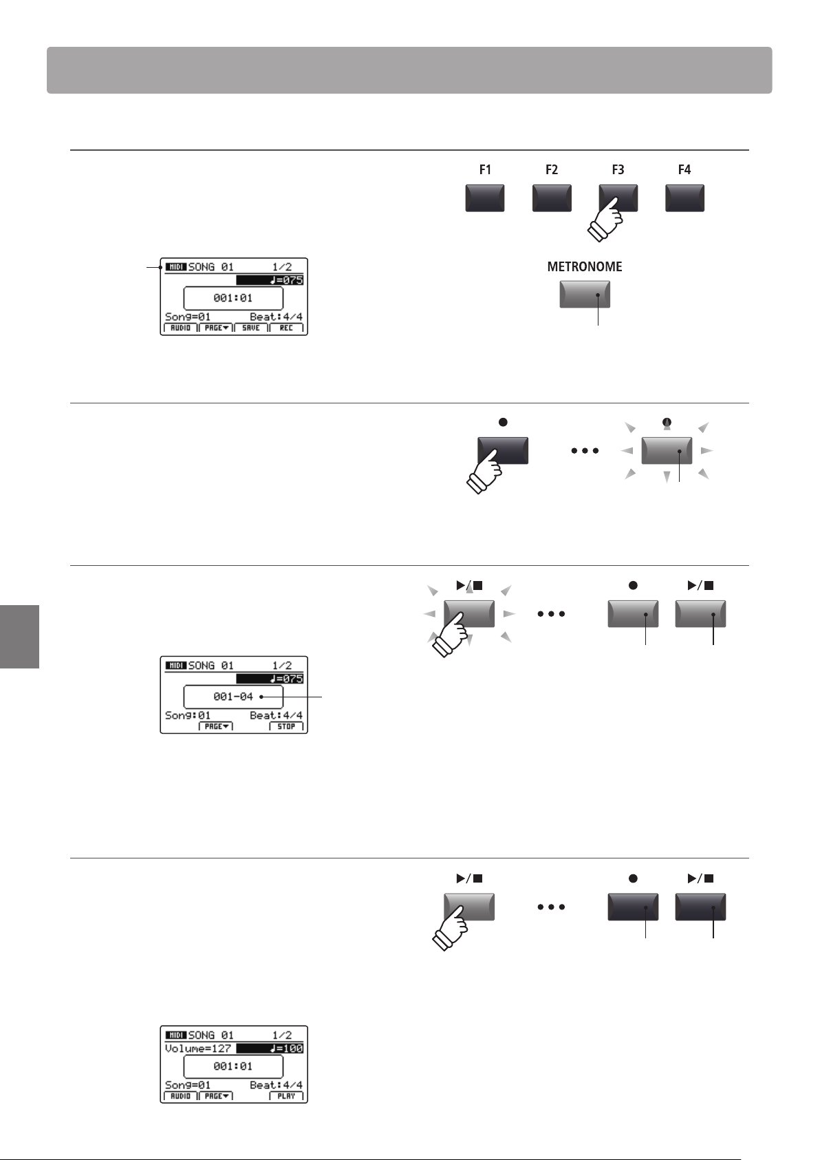
98
Recorder
Metronome
4. Returning to the Recorder function
Press the F4 function button (BACK) to return to the recorder
function.
The LED indicator for the METRONOME button will remain lit,
indicating that the metronome function is still activated.
MIDI
recorder
selected
5. Starting the song recorder (standby mode)
Press the recorder control button.
The LED indicator for the button will start to ash, to indicate
that the recorder is in standby mode.
* The F4 function button (REC) can also be used to engage standby mode.
6. Starting the song recorder (recording)
Press the / recorder control button or F4 button (REC).
The LED indicators for the and / buttons will turn ON, a
one bar count-in will be played, and recording will start.
Count-in
bar
* Recording can also be started by pressing a key on the keyboard. In this
case, recording will start immediately and the one bar count-in will not
be played.
7. Stopping the song recorder
Press the / recorder control button.
The LED indicators for the and / buttons will turn OFF, and
recording will stop.
* The F4 function button (STOP) can also be used to stop recording.
After a brief pause, the MIDI player screen will be shown in the
LCD display.
LED indicator remains ON:
Metronome is still activated
LED indicator ashing:
Recorder is in standby mode
LED indicators ON:
Recording is in progress
* When recording with the metronome in Click mode, the metronome
sound will not be heard during playback. However, when recording with
the metronome in Rhythm mode, the drum pattern will be heard during
playback.
LED indicators OFF:
Recording has stopped
* The maximum recording capacity is approximately 90,000 notes, with
button and pedal presses also counted as one note.
* If the maximum recording capacity is reached during recording, the
recorder will stop automatically.
* Recorder songs will remain in memory after the power is turned OFF.
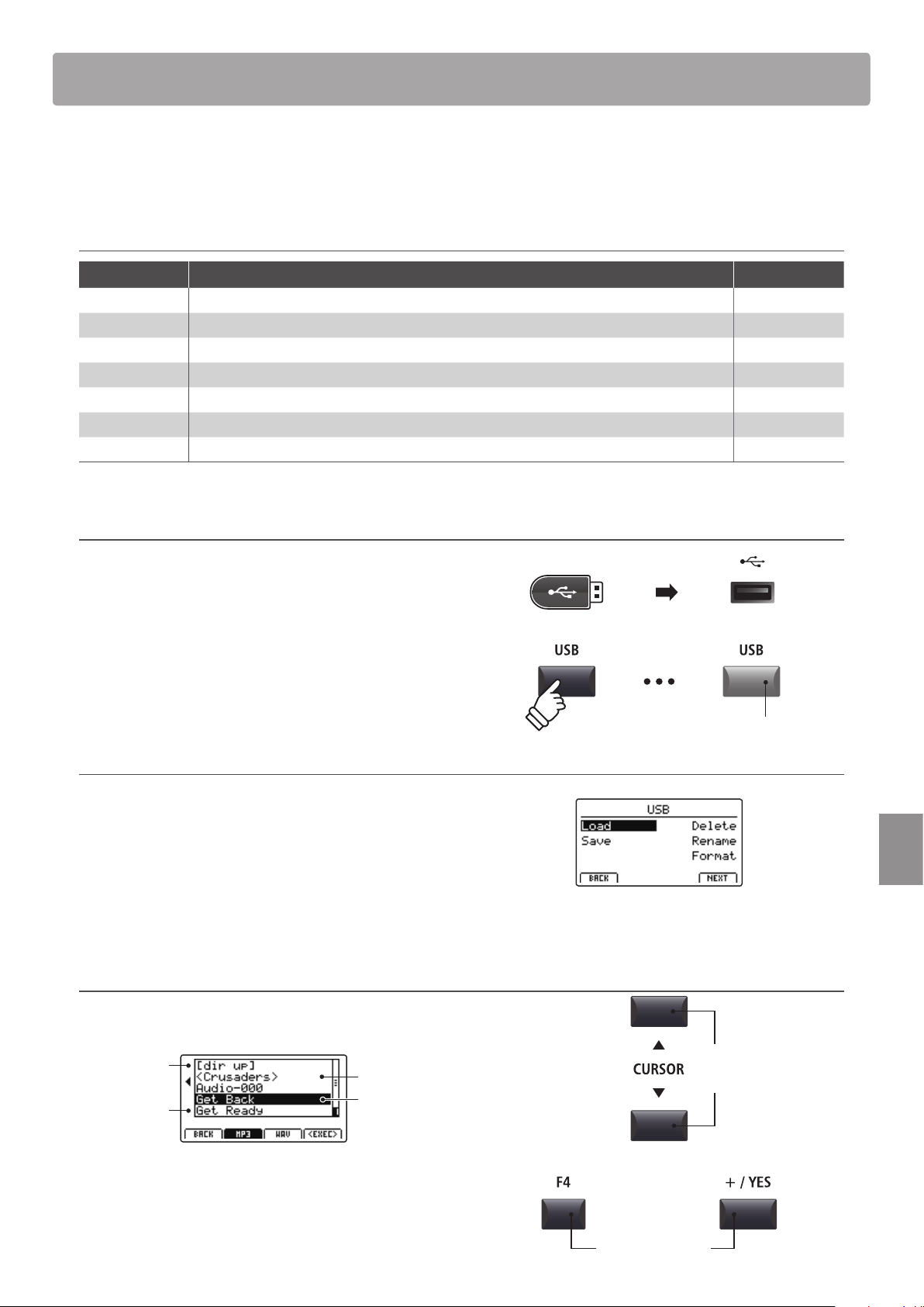
99
USB Menu
Overview of the USB Menu
The USB Menu contains functions to load, save, delete, and rename the various types of MP7SE data stored on a USB
memory device. It is also possible to format the memory device, erasing all stored data.
MP7SE data types
Data type Description File extension
SOUND A backup of a single SOUND’s parameters. .km5
SETUP A backup of a single SETUP memory. .km6
SMF A standard MIDI format (SMF) song le. .mid
Song A MP3/WAV audio le or SMF song le. .mp3, .wav, .mid
All Sound A backup of all the MP7SE’s stored SOUND parameters. .km2
All Setup A backup of all the MP7SE’s SETUP memories. .km3
All Backup A backup of all the MP7SE’s SETUP memories, SOUND parameters, and SYSTEM settings. .km4
Entering the USB Menu
Connect a USB memory device.
* USB devices should be formatted to use the ‘FAT’ or ‘FAT32’ lesystems.
Press the USB button.
The LED indicator for the USB button will turn ON, and the USB
Menu will be shown in the LCD display.
Selecting USB functions
Press the CURSOR buttons then the +/YES button or F4 function
button (NEXT) to select and enter the desired category page.
Use the same control method again to select each function.
Press the –/NO or F1 function button (BACK) to return to the
previous screen.
USB device le/folder listing screen
The MP7SE’s le/folder listing screen lists relevant les and
folders stored in the root of the USB device.
Previous
folder
Folder
File
Selection
cursor
Press the CURSOR buttons to move the selection cursor.
* Control knob A can also be used to move the selection cursor.
Press the F4 function button (EXEC) or +/YES button to select
the le or enter the selected folder.
LED indicator ON:
USB menu is selected
Move
selection
cursor
or
Select le/folder
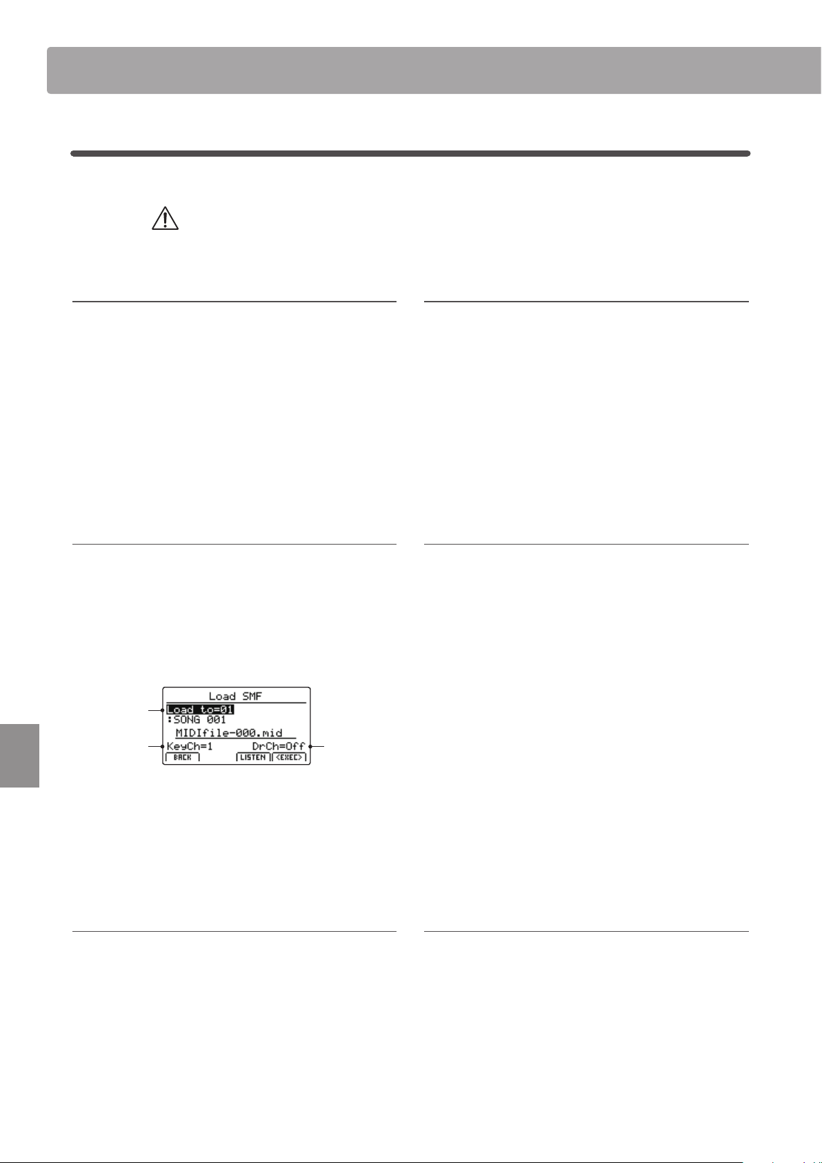
100
USB Menu
USB Menu Functions
1
Load
These functions allow data stored on a USB memory device to be loaded into the instrument’s internal memory.
Load functions will overwrite the existing data stored in internal memory.
Exercise caution when using these functions in order to prevent accidental data loss.
1. Load One Sound
This function loads a SOUND le stored on a USB memory,
replacing the preset parameters for that specic sound.
After selecting this function, select the desired SOUND le
from the le/folder listing screen.
Finally, press the F2 or F3 function buttons to conrm or cancel
the load operation.
* After loading, the SOUND will be selected automatically, and all other
sections will be turned OFF. SETUPs will also be turned OFF.
2. Load One Setup
This function loads a SETUP le stored on a USB memory device
into one of the MP7SE’s 256 SETUP memories.
After selecting this function, select the desired SETUP le from
the le/folder listing screen. Then press the BANK and SETUP
memory buttons to specify the destination SETUP memory.
Finally, press the F2 or F3 function buttons to conrm or cancel
the load operation.
* After loading, the SETUP will be selected automatically.
3. Load SMF
This function loads an SMF song le stored on a USB memory
device into the MP7SE’s internal song recorder memory.
After selecting this function, select the desired SMF le from
the le/folder listing screen. Then use the control knobs A, C,
and D to specify the destination song memory and keyboard/
drum channels.
Drum
channel
Keyboard
channel
Song
memory
Finally, press the F2 or F3 function buttons to conrm or cancel
the load operation.
* After loading, the MIDI record/playback screen will be shown in the LCD
display and the destination song memory will be selected automatically.
* For more information about the song recorder, please refer to page 69.
4. Load All Sound
This function replaces the preset parameters for all internal
sounds from an All Sound le stored on a USB memory device.
After selecting this function, select the desired All Sound le
from the le/folder listing screen.
Finally, press the F2 or F3 function buttons to conrm or cancel
the load operation.
5. Load All Setup
This function restores all SETUP memories from an All Setup le
stored on a USB memory device.
After selecting this function, select the desired All Setup le
from the le/folder listing screen.
Finally, press the F2 or F3 function buttons to conrm or cancel
the load operation.
6. Load All Backup
This function restores the parameters for all SETUP memories,
SOUND parameters, and SYSTEM settings from an All Backup
le stored on a USB memory device.
After selecting this function, select the desired All Backup le
from the le/folder listing screen.
Finally, press the F2 or F3 function buttons to conrm or cancel
the load operation.
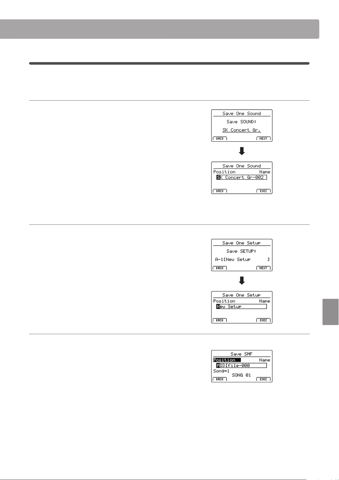
101
USB Menu
USB Menu Functions
2
Save
These functions allow data stored in the instrument’s internal memory to be saved to a USB memory device.
1. Save One Sound
This function saves the currently selected sound’s parameters
to a USB memory device.
* If the selected zone is set to EXT, the MAIN zone’s current sound will be
saved automatically.
After selecting this function, a conrmation screen will be
shown in the LCD display. Press the F4 function button (NEXT)
to continue.
Enter a name for the saved SOUND le using control knobs A
and B, then press the F4 function button (EXEC).
Finally, press the F2 or F3 function buttons to conrm or cancel
the save operation.
2. Save One Setup
This function saves a SETUP memory to a USB memory device.
After selecting this function, a conrmation screen will be
shown in the LCD display. Press the BANK and SETUP memory
buttons to specify the destination SETUP memory, then press
the F4 function button (NEXT) to continue.
Enter a name for the saved SETUP le using control knobs A and
B, then press the F4 function button (EXEC).
Finally, press the F2 or F3 function buttons to conrm or cancel
the save operation.
3. Save SMF
This function saves an internal recorder song to a USB memory
device in SMF format.
After selecting this function, the Save SMF screen will be shown
in the LCD display. Select the song memory to be saved using
control knob C, and enter a name for the saved SMF le using
control knobs A and B, then press the F4 function button (EXEC).
Finally, press the F2 or F3 function buttons to conrm or cancel
the save operation.
* For more information about the song recorder, please refer to page 69.
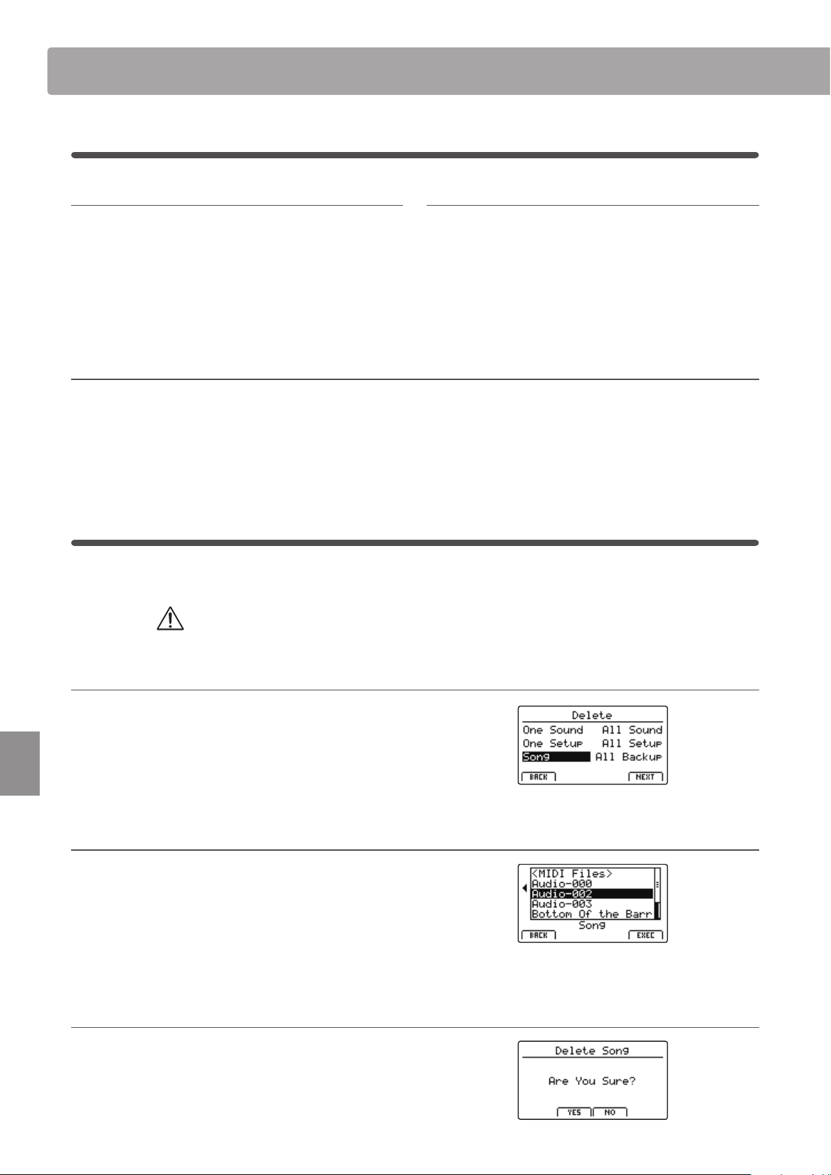
102
USB Menu
USB Menu Functions
4. Save All Sound
This function saves the parameters for all internal sounds to a
USB memory device.
After selecting this function, enter a name for the saved
AllSound le using control knobs A and B, then press the F4
function button (EXEC).
5. Save All Setup
This function saves all of the SETUP memories stored in the
instrument to a USB memory device.
After selecting this function, enter a name for the saved AllSetup
le using control knobs A and B, then press the F4 function
button (EXEC).
6. Save All Backup
This function saves the parameters for all internal sounds, all SETUP memories, and all SYSTEM settings to a USB memory device.
After selecting this function, enter a name for the saved AllBackup le using control knobs A and B, then press the F4 function button
(EXEC).
3
Delete
These functions allow data stored on a USB memory device to be deleted.
Delete functions will erase data from the connected USB memory device.
Exercise caution when using these functions in order to prevent accidental data loss.
1. Selecting the type of le to delete
Press the CURSOR buttons then the +/YES button or F4 function
button (NEXT) to select the type of le to be deleted.
Press the –/NO or F1 function button (BACK) to return to the
previous screen.
2. Selecting the le to delete
Turn control knob A or press the CURSOR buttons to move the
selection cursor. Then press the +/YES button or F4 function
button (EXEC) to delete the le.
Press the –/NO or F1 function button (BACK) to return to the
previous screen.
3. Conrming the le deletion
Press the F2 function button (YES) or F3 function button (NO) to
conrm or cancel the delete le operation.
After deleting the le, the main USB Menu will screen will be
shown in the LCD display.
2
Save (cont.)
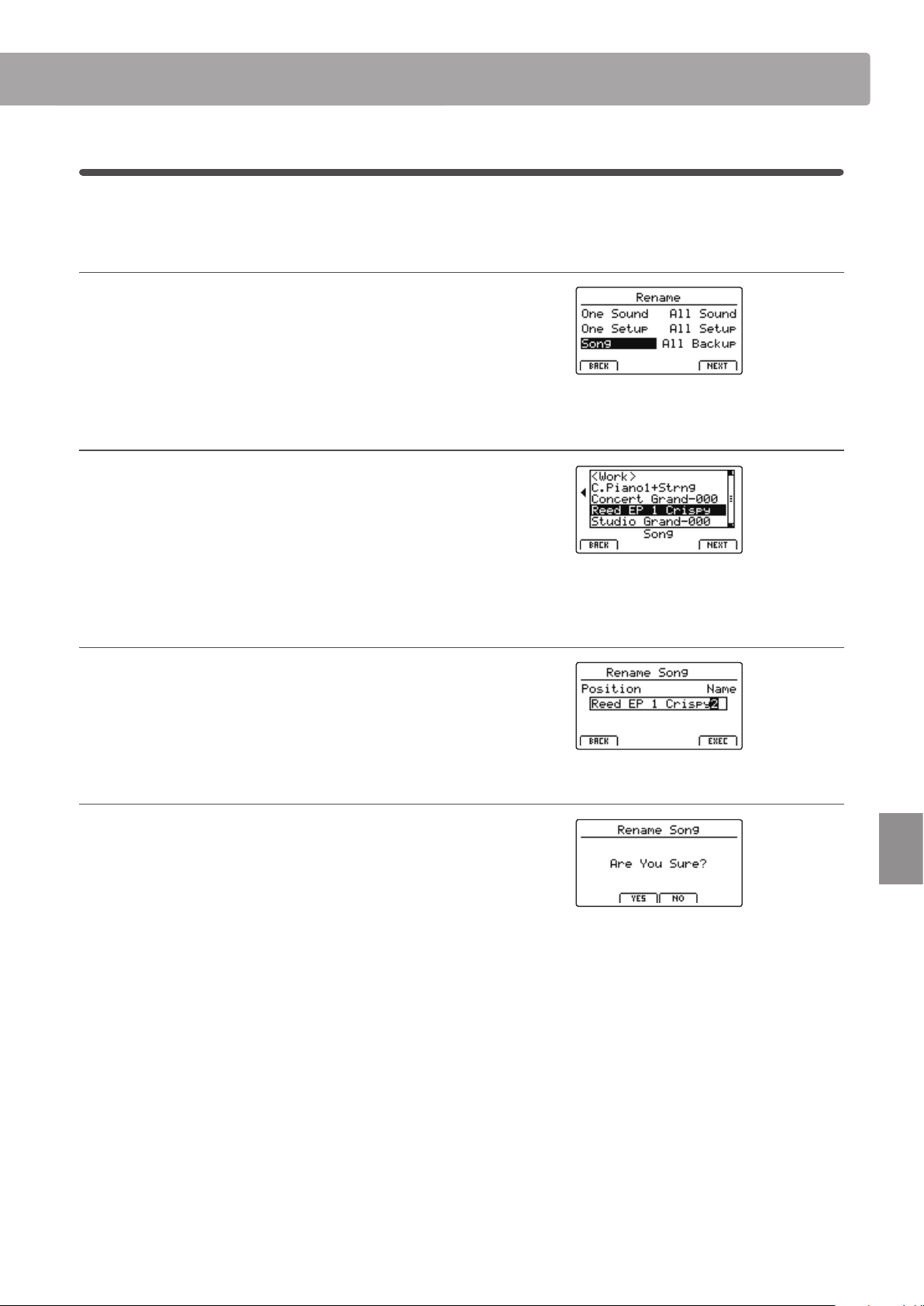
103
USB Menu
USB Menu Functions
4
Rename
These functions allow data stored on a USB memory device to be renamed.
1. Selecting the type of le to rename
Press the CURSOR buttons then the +/YES button or F4 function
button (NEXT) to select the type of le to be renamed.
Press the –/NO or F1 function button (BACK) to return to the
previous screen.
2. Selecting the le to rename
Turn control knob A or press the CURSOR buttons to move the
selection cursor. Then press the +/YES button or F4 function
button (EXEC) to rename the le.
Press the –/NO or F1 function button (BACK) to return to the
previous screen.
3. Renaming the le
Turn control knobs A and B to move the position of the cursor
and change the character, then press F4 function button (EXEC)
to rename the le.
4. Conrming the le rename
Press the F2 function button (YES) or F3 function button (NO) to
conrm or cancel the rename le operation.
After renaming the le, the main USB Menu will screen will be
shown in the LCD display.
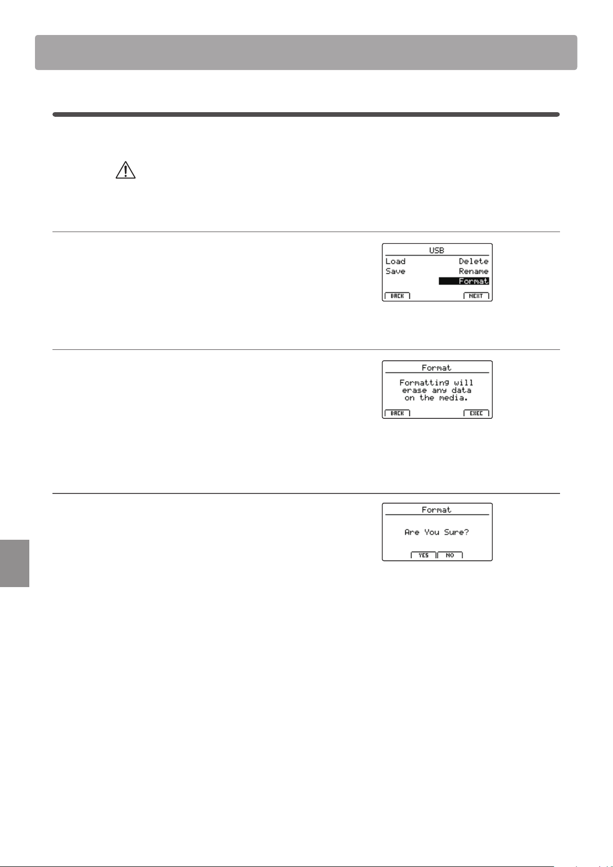
104
USB Menu
USB Menu Functions
5
Format
This function allows a USB memory device to be formatted, erasing all stored data.
The Format function will erase all data stored on the connected USB memory device.
Exercise caution when using this function in order to prevent accidental data loss.
1. Selecting the Format function
Press the CURSOR buttons then the +/YES button or F4 function
button (NEXT) to select the format function.
Press the –/NO or F1 function button (BACK) to return to the
previous screen.
2. First conrmation prompt
The rst conrmation prompt will be shown in the LCD display.
Press the +/YES button or F4 function button (EXEC) to select
the proceed with the format function.
Press the –/NO or F1 function button (BACK) to return to the
previous screen.
3. Final conrmation prompt
A nal conrmation prompt will be shown in the LCD display.
Press the +/YES button or F4 function button (EXEC) to select
the proceed with the format function.
Press the –/NO or F1 function button (BACK) to return to the
previous screen.
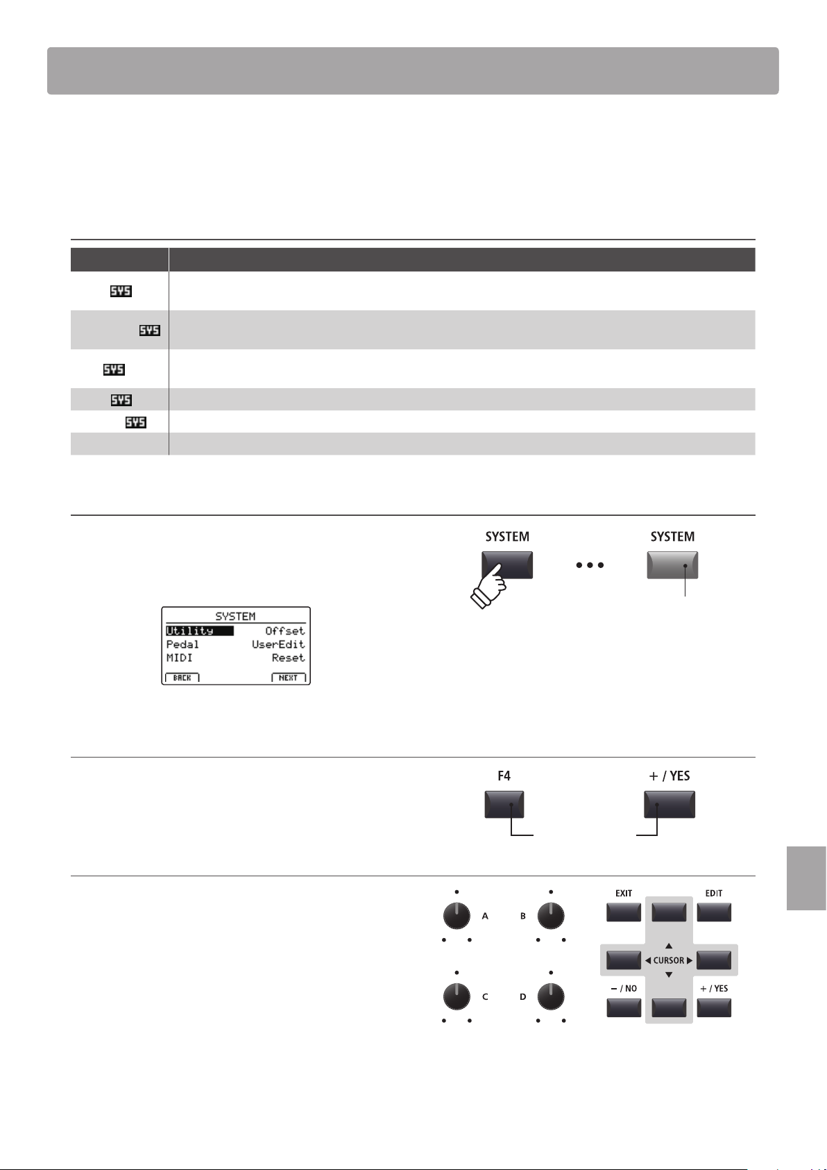
105
SYSTEM Menu
The SYSTEM menu contains parameters and settings that aect the general operation of the MP7SE. These settings
are grouped into six categories: Utility, Pedal, MIDI, Oset, User Edit, and Reset. SYSTEM parameters will be
memorised automatically when instrument is turned OFF.
SYSTEM Menu parameters
Category Parameters
Utility
System Tuning, E. SW Mode, Knob Action, Volume Fader Action, LCD Contrast, LCD Reverse,
Input Level, Audio Output Mode, Lock SW Mode, Auto Power O, SW1 Mode, SW2 Mode
Pedal/Mod.
Damper Pedal Mode, Half Pedal Adjust, FSW Pedal Mode, FSW Pedal Polarity, Modulation Wheel Curve,
EXP Pedal Curve, EXP Pedal Calibrate, Right Pedal Mode, Center Pedal Mode, Left Pedal Mode
MIDI
System Channel, Key to MIDI, Key to USB, MIDI to MIDI, MIDI to USB, USB to MIDI, SETUP Program, SETUP Bank,
SETUP Volume, SETUP Knobs, Receive Mode, Receive Channel, Program Mode
Oset
EQ Oset On/O, Reverb Oset, EQ Oset Low, EQ Oset High, EQ Oset Mid1, EQ Oset Mid2
User Edit
User Touch Curve, User Temperament, User KeyVolume, User Stretch, User Voicing
Reset One Sound, All Sound, One Setup, All Setup, System, Power On, Recorder, Factory
Entering the SYSTEM Menu
Press the SYSTEM button.
The LED indicator for the SYSTEM button will turn ON, and the
SYSTEM Menu will be shown in the LCD display.
Selecting the SYSTEM parameter category
Press the CURSOR buttons to select, and then the F4 function
button (NEXT) or +/YES button to enter the desired category.
Adjusting SYSTEM parameters
Turn the four control knobs (A, B, C, D) to adjust the parameters
assigned to those knob.
Parameters can also be adjusted by using the CURSOR buttons
to move the selection cursor, and +/YES or –/NO buttons to
increase or decrease the value of the selected parameter.
Press the F2 and F3 function buttons to cycle through the
SYSTEM menu pages.
* The CURSOR buttons can also be used to cycle through pages.
* The adjusted SYSTEM parameters will be memorised automatically.
Overview of the SYSTEM Menu
LED indicator ON:
SYSTEM menu is selected
or
Select category
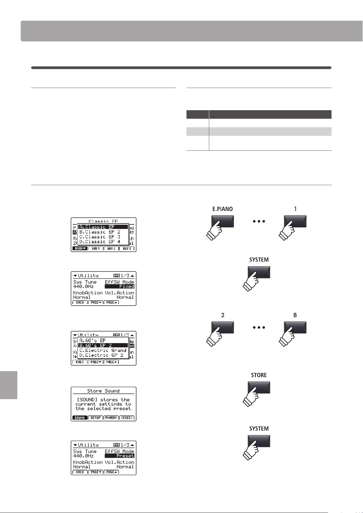
106
SYSTEM Menu
SYSTEM Menu Parameters & Functions
1
Utility
1. System Tuning
value: 427.0 ~ 453.0 Hz
This parameter sets the global master tuning of the MP7SE in
0.5Hz increments.
* The default setting is A = 440.0 Hz
2. E. SW Mode preset, temp., fixed
This function determines whether selecting sounds aects the
EFX, AMP, and REVERB button state and associated settings.
Mode Description
Preset ON/OFF state is recalled when selecting sounds.
Temp. ON/OFF state is not recalled when selecting sounds.
Fixed
ON/OFF state and eect settings are not recalled when
selecting sounds.
* The default setting is Preset.
Using the E.SW Mode ‘Fixed’ function to copy eects settings
The following procedure can be used to ‘copy’ favourite eects settings to multiple sounds within the same section.
1. First, select the sound with the desired eects settings.
2. Enter the SYSTEM:Utility menu and set E.SW Mode to Fixed.
3. Next, select the sound to which the desired EFX settings
should be applied.
4. Then, store the sound (with the desired EFX settings) to memory.
5. Finally, restore the E.SW Mode to Preset.
* The above procedure will ‘copy’ all EFX1/EFX and AMP settings, and the
REVERB depth setting. Other settings will not be ‘copied’.
107
SYSTEM Menu
SYSTEM Menu Parameters & Functions
3. Knob Action normal, catcH
This parameter determines the adjustment behaviour of the
four control knobs (A, B, C, D).
Mode Description
Normal Value changes immediately when control knob is turned.
Catch
Value does not change until control knob ‘catches’ the
previously stored value, thus preventing unexpected
jumps in parameter values.
* The default setting is Normal.
4. Volume Fader Action normal, catcH
This parameter determines the adjustment behaviour of the
section volume faders.
Mode Description
Normal Volume changes immediately when fader is moved.
Catch
Volume does not change until fader ‘catches’ the
previously stored volume value, thus preventing
unexpected volume jumps.
* The default setting is Normal.
5. LCD Contrast value: 1 ~ 10
This parameter adjusts the contrast of the LCD display.
The contrast becomes sharper as the value increases.
* The default setting is 5.
6. LCD Reverse on, off
This parameter inverts the black and white pixels of the LCD
display, which may improve visibility in certain situations.
* The default setting is OFF.
7. Input Level value: –18 db ~ +18 db
This parameter adjusts the gain of the MP7SE’s LINE IN jacks.
If the output level of the external device is too high, reduce the value
of this parameter. Alternatively, if the output is too low, increase the
value of this parameter.
* The default setting is 0 dB.
8. Audio Out Mode stereo, 2xmono
This parameter allows the MP7SE’s LINE OUT signal to be
changed from stereo to dual-mono.
This may be useful in certain situations, allowing one output to be
used for a monitor speaker and the other to be plugged into the
mixing console.
Mode Description
Stereo The Line-out signal is normal stereo.
2xMono The Line-out signal is mono on both jacks.
* The default setting is Stereo.
* Stereo EFX such as AutoPan will be turned OFF when 2xMono is selected.
9. Lock SW Mode 6 types
This function determines which controls will be locked when
the LOCK (
) button is pressed.
Mode Description
Panel The main control panel will be locked.
Bend The pitch bend wheel will be locked.
Mod. The modulation wheel will be locked.
Center The centre pedal will be locked.
Left The left pedal will be locked.
EXP The expression pedal (EXP) will be locked.
* The default setting is Panel Lock.
10. Auto Power O off, 15 mins., 60 mins., 120 mins.
This parameter determines the period of inactivity that should
pass before the MP7SE automatically turns OFF.
Value Description
O The Auto Power O function is disabled.
15 mins. The MP7SE will turn o after 15 minutes of inactivity.
60 mins. The MP7SE will turn o after 60 minutes of inactivity.
120 mins. The MP7SE will turn o after 120 minutes of inactivity.
* The default setting for this parameter depends on the market region.
11/12. SW1/SW2 Mode 3 functions
This parameter determines the global operation for the
assignable SW1/SW2 buttons.
SW modes
Mode Description
Normal The button will use the assigned EDIT menu function.
Setup+ The button will select the next SETUP memory.
Setup- The button will select the previous SETUP memory.
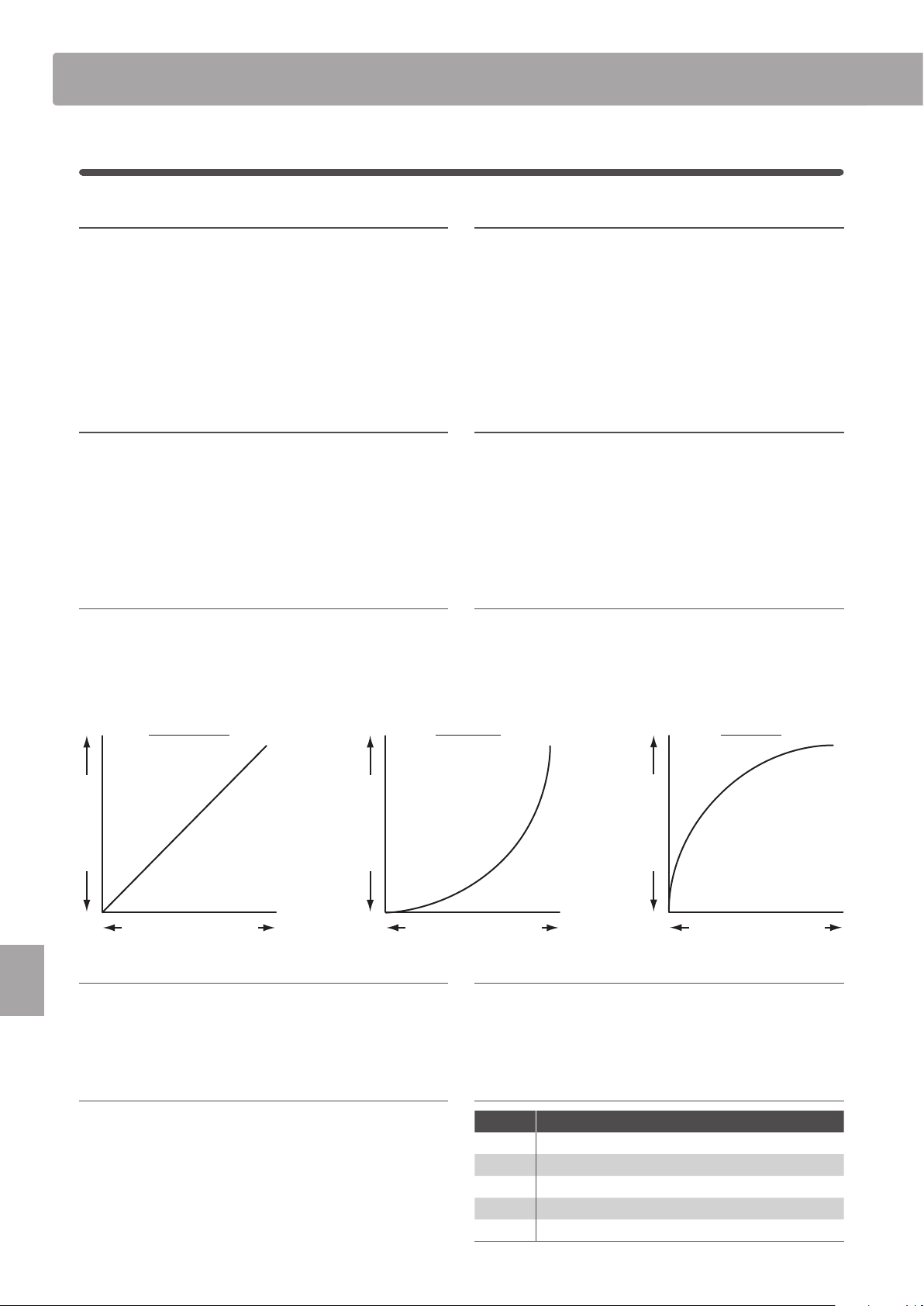
108
SYSTEM Menu
SYSTEM Menu Parameters & Functions
2
Pedal/Mod.
1. Damper Pedal Mode
5 functions
This parameter determines the global operation for the included
F-10H damper pedal.
* The default setting is Normal.
2. Half Pedal Adjust value: 1 ~ 10
This parameter adjusts the point at which the damper/sustain
pedal becomes eective (i.e. when the dampers of the piano
begin to lift from the strings).
This parameter may be useful for pianists that habitually rest their
right foot on the damper/sustain pedal, but do not necessarily wish
to sustain the sound.
* The default setting is 5.
3. FSW Pedal Mode
5 functions
This parameter determines the global operation for the
footswitch (FSW) pedal.
* The default setting is Normal.
4. FSW Pedal Polarity normal, reverse
This parameter changes the polarity of the ordinary footswitch
(FSW) pedal.
The MP7SE’s foot switch terminal is designed for use with ‘Normal
Close’ polarity pedals. If using a foot switch with ‘Normal Open’
polarity, please change this parameter to Reverse.
* The default setting is Normal.
5. Modulation Wheel Curve normal, slow, fast
This parameter changes the output level curve for the
modulation wheel, providing additional control over the speed
of modulation wheel controlled eects.
* The default setting is Normal.
6. EXP Pedal Curve normal, slow, fast
This parameter changes the output level curve for the
connected expression (EXP) pedal, providing additional control
over the speed of expression pedal controlled eects.
* The default setting is Normal.
Output Level
Pedal/Wheel Position
Normal curve
Output Level
Pedal/Wheel Position
Slow curve
Output Level
Pedal/Wheel Position
Fast curve
7. Right Pedal Mode 5 functions
This parameter determines the global operation for the right
pedal of the optional GFP-3 pedal unit.
* The default setting is Normal.
8. Center Pedal Mode 5 functions
This parameter determines the global operation for the centre
pedal of the optional GFP-3 pedal unit.
* The default setting is Normal.
9. Left Pedal Mode 5 functions
This parameter determines the global operation for an ordinary
foot switch pedal or the left pedal of the optional GFP-3 pedal
unit.
* The default setting is Normal.
Pedal modes
Mode Description
Normal The pedal will use the assigned EDIT menu function.
Setup+ The pedal will select the next SETUP memory.
Setup- The pedal will select the previous SETUP memory.
Playback The pedal will start/stop song playback.
Metro. The pedal will start/stop the metronome.
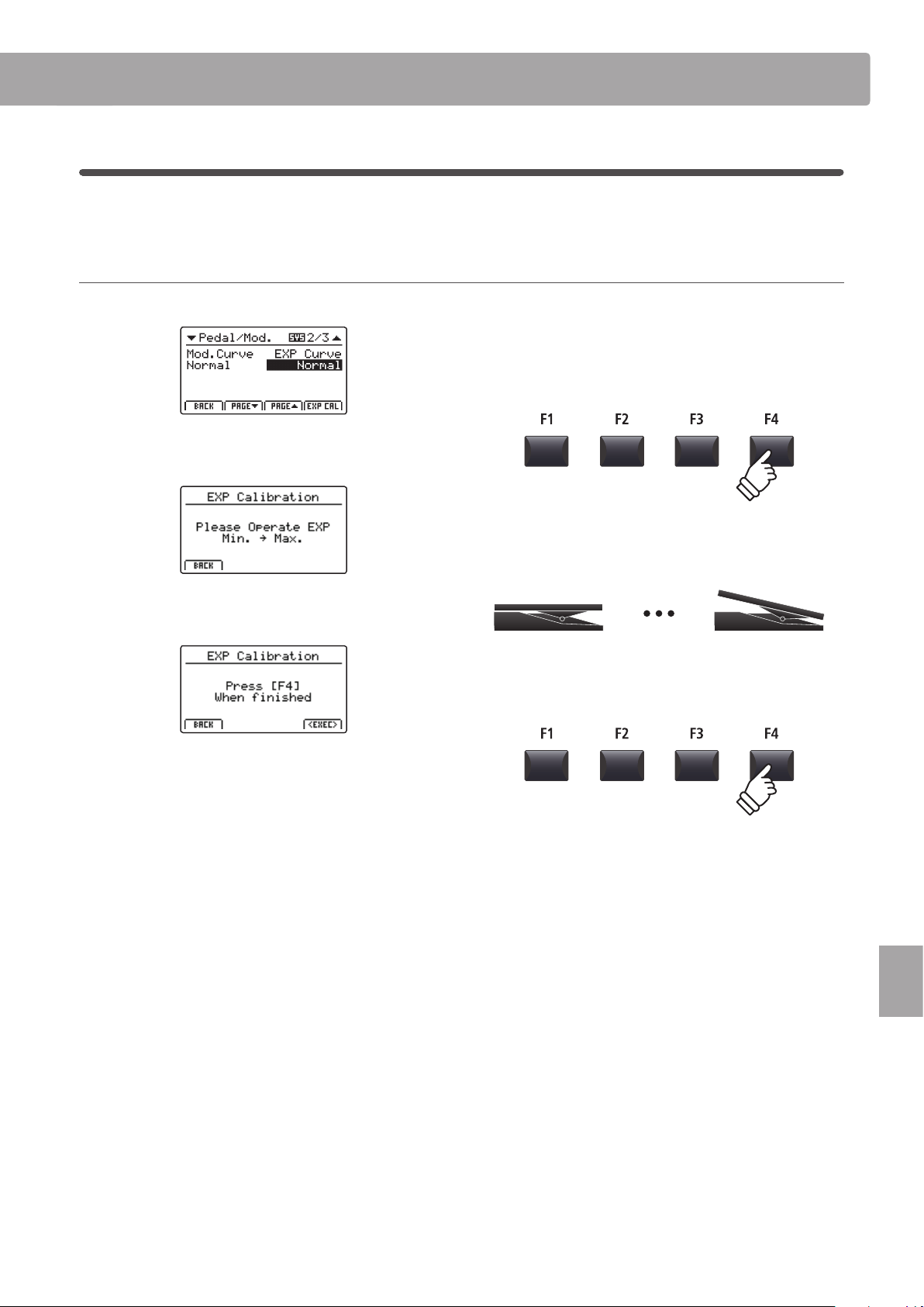
109
SYSTEM Menu
SYSTEM Menu Parameters & Functions
Expression pedal calibration
Depending on the brand and model of expression pedal connected to the MP7SE, it may be necessary to use the
calibration function to ensure that the pedal’s minimum and maximum range of values are detected correctly.
Calibrating the EXP pedal
Select the third page (3/3) of the Pedal SYSTEM menu.
Press the F4 function button (EXP CAL) to show the expression
pedal calibration screen in the LCD display.
Press the expression pedal to the minimum and maximum
positions several times to transmit the full range of values.
Press F4 function button (EXEC) to complete the expression
pedal calibration.
The full range of operation for the connected expression pedal
will be calculated automatically.
110
SYSTEM Menu
SYSTEM Menu Parameters & Functions
3
MIDI
1. System Channel
value: 01cH ~ 16cH
This parameter determines the System MIDI channel used to
receive MIDI messages when Receive Mode is set to Panel.
* The default setting is 01Ch.
2. Key to MIDI
on, off
This parameter determines whether or not keyboard events are
transmitted via MIDI OUT.
* The default setting is ON.
3. Key to USB on, off
This parameter determines whether or not keyboard events are
transmitted via USB-MIDI.
* The default setting is ON.
4. MIDI to MIDI on, off
This parameter determines whether or not received MIDI IN
events are transmitted via MIDI OUT.
* The default setting is OFF.
5. MIDI to USB
on, off
This parameter determines whether or not received MIDI IN
events are transmitted via USB-MIDI.
* The default setting is OFF.
6. USB to MIDI
on, off
This parameter determines whether or not received USB-MIDI
events are transmitted via MIDI OUT.
* The default setting is OFF.
7. SETUP Program on, off
This parameter determines whether or not the Send Program
parameter in the EDIT menu (MIDI OUT/SETUP) is enabled.
* For more information about the Send Program parameter, please refer to
page 56.
* The default setting is OFF.
8. SETUP Bank on, off
This parameter determines whether or not the Send Bank
parameter in the EDIT menu (MIDI OUT/SETUP) is enabled.
* For more information about the Send Bank parameter, please refer to
page 56.
* The default setting is OFF.
9. SETUP Volume on, off
This parameter determines whether or not the Send Volume
parameter in the EDIT menu (MIDI OUT/SETUP) is enabled.
*
For more information about the Send Volume parameter, please refer to page 56.
* The default setting is OFF.
10. SETUP Knobs on, off
This parameter determines whether or not the Send Knobs
parameter in the EDIT menu (MIDI OUT/SETUP) is enabled.
*
For more information about the Send Knobs parameter, please refer to page 56.
* The default setting is OFF.
11. Receive Mode panel, multi, omni on
This parameter determines how the MP7SE receives MIDI data.
Mode Description
Panel
Only data received from the designated system channel
will be sent to the MAIN, SUB1, SUB2, and SUB3 zones.
* With this setting, layer and internal eects will be available.
Multi
Data received from all MIDI channels (ch1~ch16) will be
sent to the MAIN and SUB1, SUB2, SUB3 zones or MIDI
channels.
* With this setting, an additional set of pages will appear,
allowing MIDI Receive Channels to be specied.
Omni On
Received data controls the whole panel, regardless of
the MIDI channel.
* The default setting is Panel.
12. Program Change Mode panel, gm
This parameter determines the sound numbering format that is
used when sending MIDI Program Change information.
Mode Description
Panel
Program Change data is sent in accordance with the
instrument’s panel button numbering format.
GM
Program Change data is sent in accordance with the
standard GM numbering format.
*
Select this setting when connecting the MP7SE to GM devices.
* The default setting is Panel.
13. Receive Channel
on, off,
m
ain, sub1, sub2, sub3
When Receive Mode is set to ‘Multi’, these additional settings
determine whether the Receive Channel is turned ON or OFF, or
assigned to a specic zone.
* When set to MAIN, SUB1, SUB2, or SUB3, the MIDI input signal will still
trigger sounds even when the zone is turned OFF.
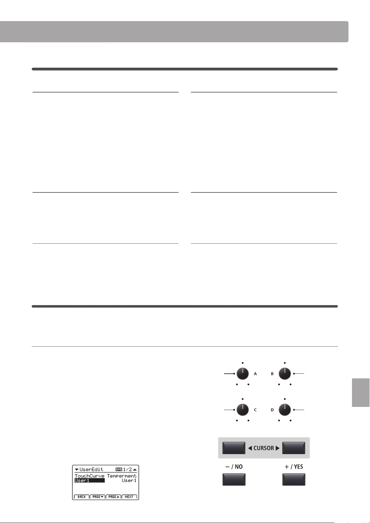
111
SYSTEM Menu
SYSTEM Menu Parameters & Functions
4
Oset
1. EQ Oset ON/OFF
This parameter turns the EQ Oset function ON or OFF.
The EQ Oset function may be useful when performing at a venue
with certain room acoustics, or simply dierent amplier and
speaker equipment to that used normally. The Oset values can
be adjusted to create a ‘baseline’ character for the instrument,
rather than readjusting the EQ settings prepared for each SETUP.
* The default setting is OFF.
* The EQ Oset values will be added to the EQ values dened in each
SETUP. The combined EQ values are limited to ±10 dB.
2. Reverb Oset
This parameter adjusts the reverb depth oset, allowing the
reverb for all sound section to be reduced globally.
Similar to the EQ Oset function, Reverb Oset may be useful
when performing at a venue with reective acoustics, or when
connecting the instrument to a PA system with reverb pre-applied.
The reverb oset depth is reduced globally for all sound sections,
negating the need to readjust reverb settings for each SETUP.
* The default setting is 100%.
3. EQ Oset Low
This parameter adjusts the EQ Oset gain for the low range
frequency band.
* The default setting is 0 dB.
4. EQ Oset High
This parameter adjusts the EQ Oset gain for the high range
frequency band.
* The default setting is 0 dB.
5. EQ Oset Mid1
This parameter adjusts the EQ Oset gain for the Mid1 range
frequency band.
* The default setting is 0 dB.
6. EQ Oset Mid2
This parameter adjusts the EQ Oset gain for the Mid2 range
frequency band.
* The default setting is 0 dB.
5
User Edit
The User Edit category contains functions to create custom touch curves and keyboard temperaments.
Selecting the User Touch Curve / Temperament / Key Volume / Stretch Tuning to edit
After selecting the User Edit SYSTEM menu category:
Turn control knob A to select the desired User Touch Curve.
Turn control knob B to select the desired User Temperament.
Turn control knob C to select the desired User Key Volume.
Turn control knob D to select the desired User Stretch Tuning.
The User Touch Curve, User Temperament, User Key Volume,
and User Stretch Tuning can also be selected by using the
CURSOR buttons and +/YES or –/NO buttons.
on, off value: 0% ~ 100%
value: –10 db ~ +10 db value: –10 db ~ +10 db
value: –10 db ~ +10 db value: –10 db ~ +10 db
Select User
Key Volume
Select User
Touch Curve
Select User
Stretch Tuning
Select User
Temperament
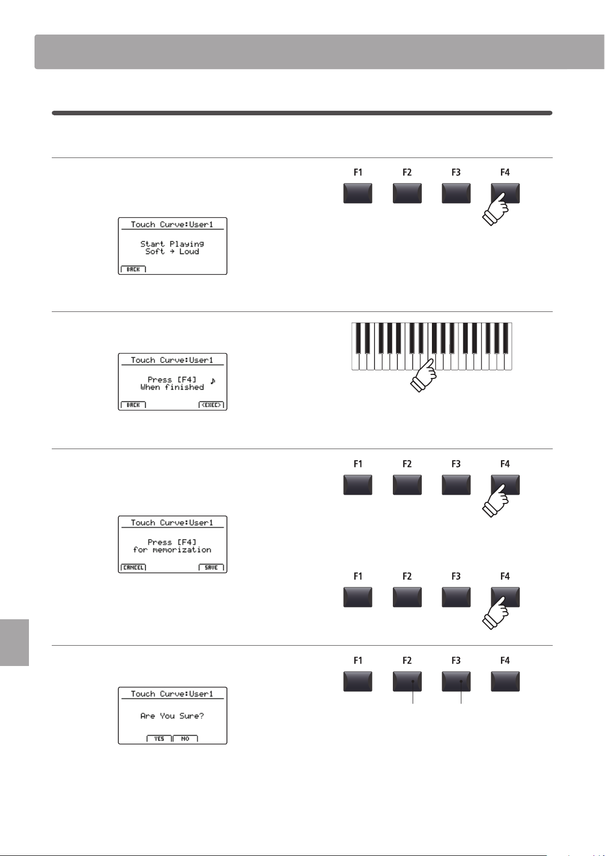
112
SYSTEM Menu
Creating a User Touch Curve
1. Starting the User Touch Curve analysis
After selecting the User Touch Curve memory to be edited:
Press the F4 function button (NEXT) to start the User Touch
Curve analysis.
2. Capturing the dynamic range
Play the piano dynamically from very soft to very loud, allowing
the instrument to analyse the personal playing technique.
3. Completing the User Touch Curve analysis
Press the F4 function button (EXEC) to complete the User Touch
Curve analysis.
A conrmation screen will be shown in the LCD display.
Play the piano to check the newly created touch curve, then
press the F4 function button (SAVE) to store it to user memory.
4. Storing the User Touch Curve
Press the F2 button (YES) to conrm the store operation, or the
F3 button (NO) to return to the previous screen.
* The +/YES and –/NO buttons can also be used to conrm or cancel the
store operation.
The new User Touch Curve will be used for the selected sound
section temporarily.
SYSTEM Menu Parameters & Functions
F3 button:
NO: Cancel
F2 button:
YES: Conrm
* More than one attempt may be required in order to create an accurate
User Touch Curve.
* Reducing the master volume fader to the lowest position before creating
the User Touch Curve may help to reduce user distractions, thus improving
accuracy.
* Please use the Store SOUND function to ensure that the created User
Touch Curve is used automatically when the sound is selected.
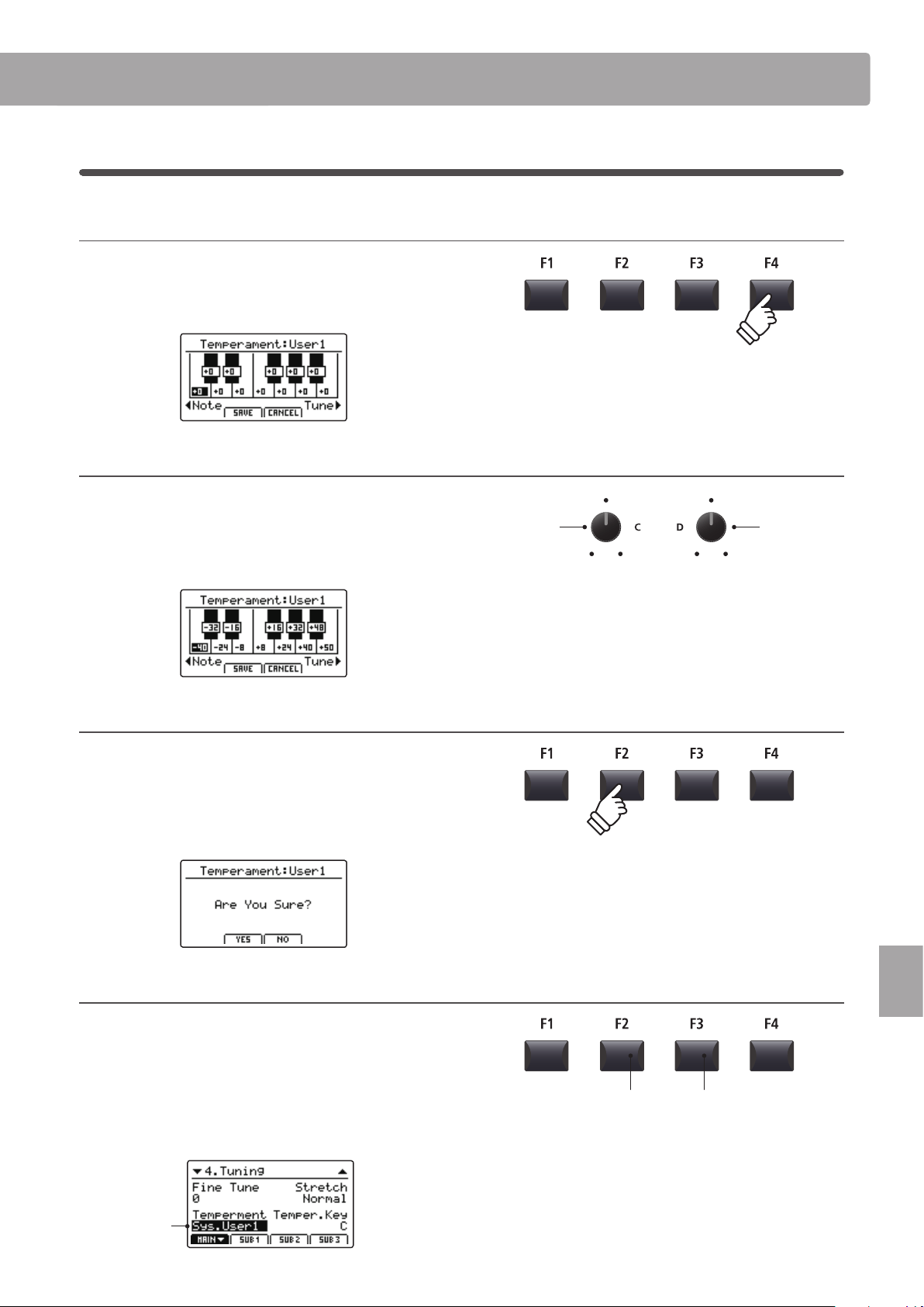
113
SYSTEM Menu
SYSTEM Menu Parameters & Functions
Creating a User Temperament
1. Selecting the User Temperament editor
After selecting the User Temperament to be edited:
Press the F4 function button (NEXT) to select the User
Temperament editor.
2. Adjusting the User Temperament
Turn control knob C to select the note to be adjusted.
Turn control knob D to adjust the pitch of the selected note.
* The pitch of each key can be adjusted within the range of –50 ~ +50 cents.
One semi-tone = 100 cents.
* To select a note directly, press the desired key.
3. Saving the User Temperament
After adjusting the note pitches:
Press the F2 function button (SAVE) to save the adjusted User
Temperament.
A store conrmation screen will be shown in the LCD display.
4. Conrming the store operation
Press the F2 button (YES) to conrm the store operation, or the
F3 button (NO) to return to the previous screen.
* The +/YES and –/NO buttons can also be used to conrm or cancel the
store operation.
The new User Temperament will be used for the selected sound
section temporarily.
Selected User
Temperament
F3 button:
NO: Cancel
F2 button:
YES: Conrm
Select note Adjust pitch
* Please use the Store SOUND function to ensure that the created User
Temperament is used automatically when the sound is selected.
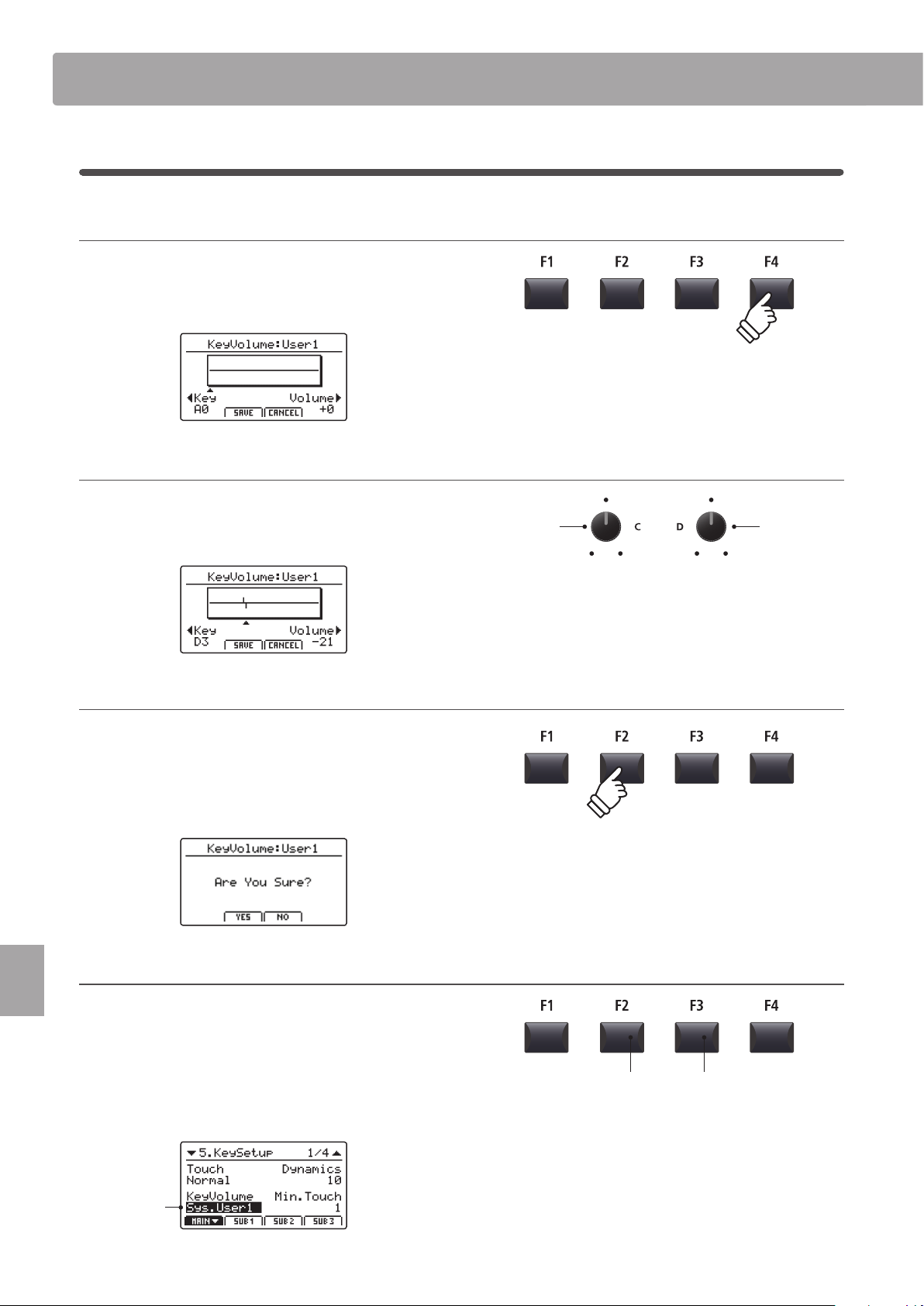
114
SYSTEM Menu
Creating a User Key Volume
1. Selecting the User Key Volume editor
After selecting the User Key Volume to be edited:
Press the F4 function button (NEXT) to select the User Key
Volume editor.
2. Adjusting the User Key Volume
Turn control knob C to select the key to be adjusted.
Turn control knob D to adjust the volume of the selected key.
* The volume of each key can be adjusted within the range of –50 ~ +50.
3. Saving the User Key Volume
After adjusting the key volumes:
Press the F2 function button (SAVE) to save the adjusted User
Key Volume.
A store conrmation screen will be shown in the LCD display.
4. Conrming the store operation
Press the F2 button (YES) to conrm the store operation, or the
F3 button (NO) to return to the previous screen.
* The +/YES and –/NO buttons can also be used to conrm or cancel the
store operation.
The new User Key Volume will be used for the selected sound
section temporarily.
Selected User
Key Volume
F3 button:
NO: Cancel
F2 button:
YES: Conrm
Select key Adjust volume
SYSTEM Menu Parameters & Functions
* Please use the Store SOUND function to ensure that the created User Key
Volume is used automatically when the sound is selected.
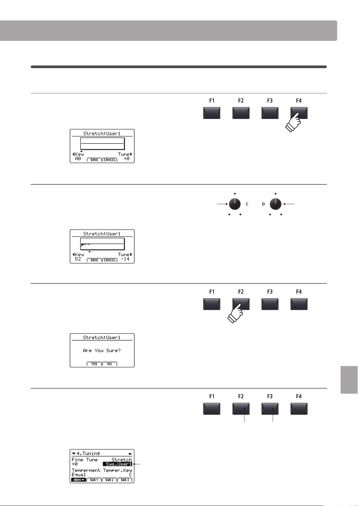
115
SYSTEM Menu
SYSTEM Menu Parameters & Functions
Creating a User Stretch Tuning
1. Selecting the User Stretch Tuning editor
After selecting the User Stretch Tuning to be edited:
Press the F4 function button (NEXT) to select the User Stretch
Tuning editor.
2. Adjusting the User Stretch Tuning
Turn control knob C to select the key to be adjusted.
Turn control knob D to adjust the pitch of the selected key.
* The pitch of each key can be adjusted within the range of –50 ~ +50 cents.
One semi-tone = 100 cents.
* To select a note directly, press the desired key.
3. Saving the User Stretch Tuning
After adjusting the key pitches:
Press the F2 function button (SAVE) to save the adjusted User
Stretch Tuning.
A store conrmation screen will be shown in the LCD display.
4. Conrming the store operation
Press the F2 button (YES) to conrm the store operation, or the
F3 button (NO) to return to the previous screen.
* The +/YES and –/NO buttons can also be used to conrm or cancel the
store operation.
The new User Stretch Tuning will be used for the selected sound
section temporarily.
Selected User
Stretch Tuning
F3 button:
NO: Cancel
F2 button:
YES: Conrm
Select key Adjust pitch
* Please use the Store SOUND function to ensure that the created User
Stretch Tuning is used automatically when the sound is selected.
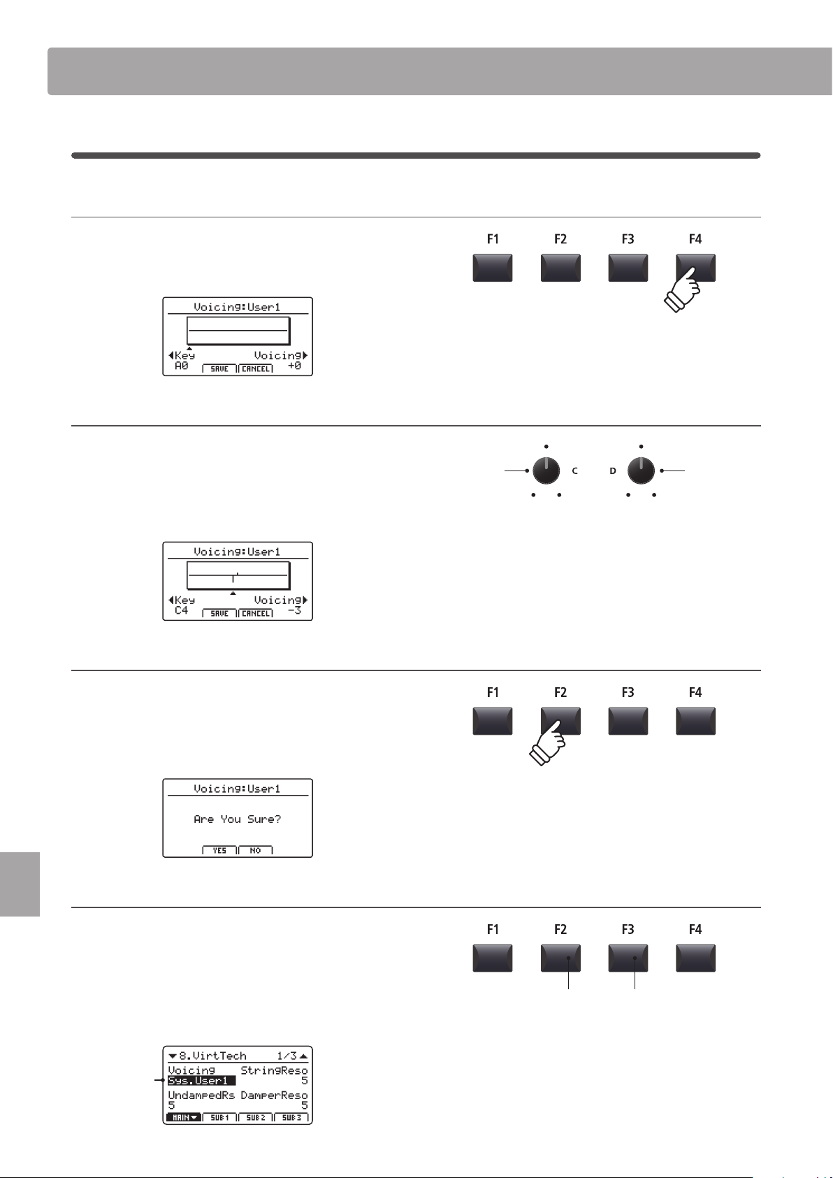
116
SYSTEM Menu
SYSTEM Menu Parameters & Functions
Creating a User Voicing
1. Selecting the User Voicing Tuning editor
After selecting the User Voicing to be edited:
Press the F4 function button (NEXT) to select the User Voicing
editor.
2. Adjusting the User Vocing
Turn control knob C to select the key to be adjusted.
Turn control knob D to adjust the voicing of the selected key.
* The User Voicing value can be adjusted within the range of –5 ~ +5, with
lower values creating a mellower sound and higher values creating a
brighter sound.
* To select a note directly, press the desired key.
3. Saving the User Voicing
After adjusting the user voicing value:
Press the F2 function button (SAVE) to save the adjusted User
Voicing.
A store conrmation screen will be shown in the LCD display.
4. Conrming the store operation
Press the F2 button (YES) to conrm the store operation, or the
F3 button (NO) to return to the previous screen.
* The +/YES and –/NO buttons can also be used to conrm or cancel the
store operation.
The new User Voicing will be used for the selected sound
section temporarily.
Selected User
Voicing
F3 button:
NO: Cancel
F2 button:
YES: Conrm
Select key Adjust voicng
* Please use the Store SOUND function to ensure that the created User
Voicing is used automatically when the sound is selected.
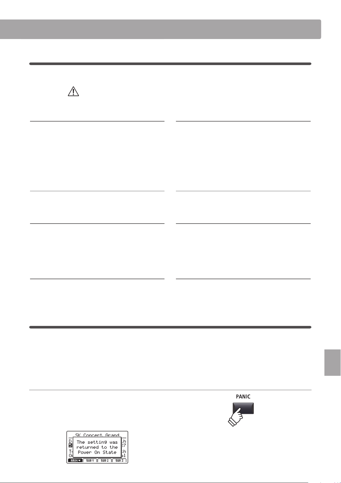
117
SYSTEM Menu
SYSTEM Menu Parameters & Functions
6
Reset
The Reset category contains functions to reset sounds, setups, and settings back to the original factory default.
Once performed, these Reset functions cannot be undone.
Exercise caution when using this function in order to prevent accidental data loss.
1. Reset One Sound
This function resets the currently selected sound to the factory
default.
The currently selected sound will be shown in the LCD display.
* It is also possible to select the sound to be reset by pressing the sound
category and variation buttons.
2. Reset One Setup
This function resets the currently selected SETUP memory to
the factory default.
The currently selected SETUP will be shown in the LCD display.
* It is also possible to select the SETUP memory to be reset by pressing the
BANK buttons and SETUP memory buttons.
3. Reset All Sound
This function resets all sounds to the factory default.
4. Reset All Setup
This function resets all SETUP memories to the factory default.
5. Reset System
This function resets all SYSTEM parameters, including Utility,
Pedal, Oset, and MIDI parameters in the SYSTEM menu, and
SETUP, Transmit, and MMC parameters in the MIDI section EDIT
menu.
6. Reset PowerOn
This function resets the PowerOn memory to the factory
default.
7. Reset Recorder
This function resets all internal song recorder memories.
8. Factory Reset
This function performs a global reset of all sounds, SETUPs,
SYSTEM settings, and internal song recorder memories.
Panic button
The PANIC button restores all internal sounds to their default PowerOn setting, and also sends the AllNoteO and
ResetAll Controller MIDI messages to any connected devices (01ch ~ 16ch).
This is a useful function to be used in emergency situations, or to immediately restore the MP7SE to a preferred
conguration.
Activating the Panic function
Press and hold the PANIC button.
After one second, the MP7SE will be returned to the default
PowerOn conguration.
hold
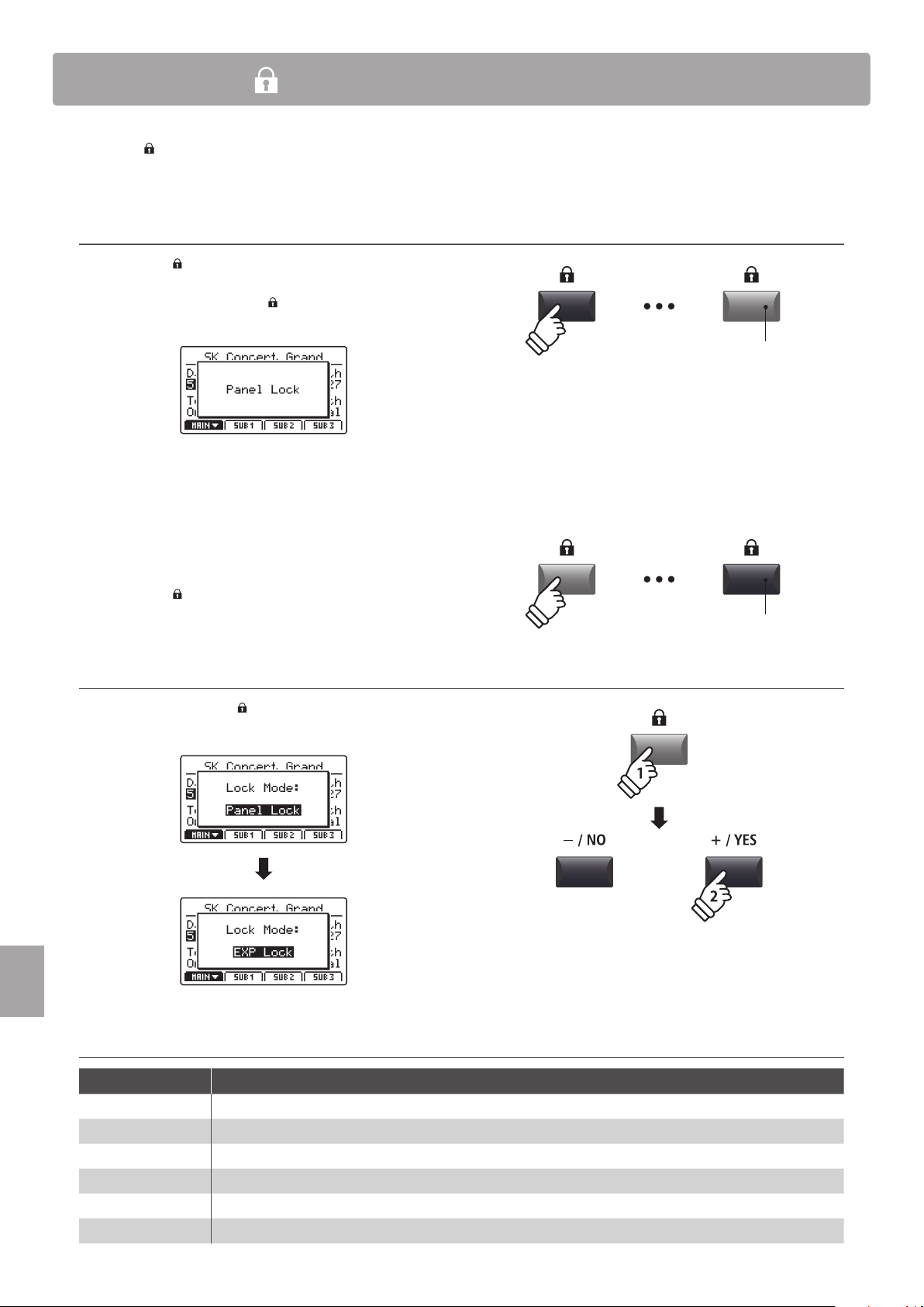
118
SYSTEM Menu
Panel Lock ( )
The Lock ( ) function allows the state of the MP7SE’s various controls to be temporarily locked, preventing accidental
button pushes, pedal presses, or wheel movements.
Activating and deactivating the Lock function
Press the LOCK ( ) button.
The LED indicator for the LOCK (
) button will turn on, and the
lock pop-up will briey be shown in the LCD display.
By default (Panel Lock mode), the Lock function will lock all of
the MP7SE’s panel buttons, knobs, and section VOLUME faders,
preventing any accidental adjustments during performances
etc.
* The VOLUME and LINE IN faders will not be locked. The keyboard will also
remain active.
Press the LOCK ( ) button again to deactivate the lock.
Changing the Lock mode
Press and hold the LOCK ( ) button, then press the +/YES or
–/NO buttons to cycle through the dierent Lock modes.
Lock modes
Lock mode Description
Panel Lock The main control panel buttons, knobs, and section VOLUME faders will be locked.
Bend Lock The pitch bend wheel will be locked.
Mod. Lock The modulation wheel will be locked.
Center Lock The centre pedal will be locked.
Left Lock The left pedal will be locked.
EXP Lock The expression pedal (EXP) will be locked.
LED indicator ON:
Lock function is activated
LED indicator OFF:
Lock function is deactivated
hold
* The Lock mode can also be changed in the SYSTEM menu. For more
information, please refer to page 107.
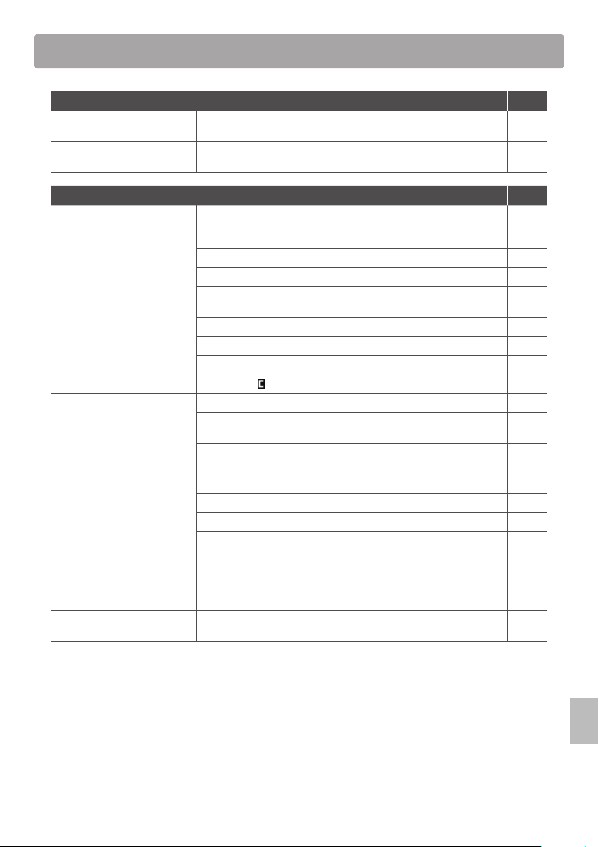
119
Appendix
Troubleshooting
Power Page
The instrument does not turn on. Check that the AC power adaptor is rmly attached to the instrument, and
connected to an AC outlet.
16
The instrument turns itself o after
a period of inactivity.
Check that the ‘Auto Power O’ setting is not enabled. 107
Sound Page
The instrument is turned on,
however no sound is produced
when the keys are pressed.
The MP7SE does not feature built-in speakers. Check that a mixer, keyboard
amplier, or headphones are connected to the instrument correctly. If using an
external mixer or amplier, check that the settings are correct.
18
Check that the MASTER VOLUME fader is not set to the lowest position. 12
Check that at least one zone’s ON/OFF button is turned on. 22
Check that at least one zone is set to INT or BOTH mode. The red LED above the
ON/OFF button (INT) should be lit.
23
Check that at least one zone’s VOLUME fader is not set to the lowest position. 22
Check that the LOCAL OFF button is not turned on. 37
Check that the expression pedal is not set to the minimum position. 17
Check that the
MasterVol parameter in the EDIT menu is not set to 0. 42
No sound is produced for a part
of zones or the sound volume is
reduced.
Check that the zone’s ON/OFF button is turned on. 22
Check that the zone is not set to EXT mode. The red LED above the ON/OFF
button (INT) should be lit.
23
Check that the zone’s VOLUME fader is not set to the lowest position. 22
Check that the zone’s ON/OFF button is not green. If it is green, please check
the Key Range parameter setting in the EDIT menu.
24
47
Check that the AMP level parameter in the EDIT menu is not set to 0. 41
Check that the modulation wheel is not assigned to the ‘Expression’ function. 49
Check that the Receive Mode parameter in the SYSTEM:MIDI menu is not
set to ‘Multi’, and the Receive Channel is not set to MAIN or SUB1~3. Some
control change messages may aect the volume faders and/or the EDIT menu
parameters in section Receive mode. If playing separate sections by MIDI
or control change is not required, please set the Receive Mode parameter to
‘Panel’.
110
158
The sound distorts when playing at
very loud volume levels.
Check that the MASTER VOLUME fader is set to an appropriate level, reducing
the volume if excessive distortion is heard.
12
120
Appendix
Troubleshooting
Strange sounds or noises are heard
when playing with piano sounds.
The MP7SE stagel piano attempts to reproduce the rich variety of tones created
by an acoustic grand piano as accurately as possible. This includes various
resonances, noises, and other subtle characteristics that contribute to the
overall piano playing experience.
While these additional tones are intended to enhance the realism of the
instrument, it is possible to reduce their prominence, or disable the eects
altogether using the following settings in the Virtual Technician menu.
The noise occurs when the damper pedal is depressed and released.
Damper Noise
52
The noise occurs after a key is released.
Fall-back Noise, Key-o Eect
52
The sound has a metallic characteristic.
Key-o Eect, Undamped Resonance, String Resonance
52
The sound is mued or too bright.
Topboard, Voicing
52
A particular key’s level/volume is higher than other keys.
User KeyVolume
114
A particular key’s pitch is heard as incorrect.
Temperament, User Temperament, User StretchTuning
45
113
115
The keyboard has no touch
responsiveness.
Check that the Touch Curve parameter in the EDIT menu is not set to O. 46
Check that the Dynamics parameter in the EDIT menu is not set to O. When
the Dynamics parameter is set to O, touch response will be disabled.
46
Check that the Trigger Mode parameter in the EDIT menu is not set to Fast.
When the Trigger Mode parameter is set to Fast/Fast2, touch response will be
disabled.
47
Some synth sounds such as SynthBass or SawLead etc. are intentionally
prepared not to use touch response. Please adjust the DCA Touch Depth or
DCF Touch Depth parameters to adjust this characteristic.
42
Staccato playing causes double
notes when Trigger Mode is set to
Fast.
This is an unfortuante consequence of using the faster trigger modes on a
hammer action keyboard, and not a failure. When staccato playing is required,
please set the Trigger Mode type to ‘Normal’.
Sound cuts out momentarily when
selecting a Tonewheel organ sound.
When entering/exiting Tonewheel organ mode (asigned to DRAWBAR sub-
categories 1~3), there may be a brief loss of sound as the tonewheel simulator is
activated/deactivated. This is normal behaviour.
32
STORE Page
OctaveShift cannot be stored to a
SOUND memory.
This is the correct behaviour. Some parameters related to the key range/
velocity functions (OctaveShift, ZoneTranspose, KeyRangeLo/Hi, VelocitySwitch)
are not stored to SOUND memory, but to SETUP memory only.
The POWER ON default setting is
dierent to the setting that it is
stored.
The POWERON memory will only store the selected SOUND position, not the
individual EDIT menu settings of that SOUND.
In order to memorise EDIT menu settings, please store each zone’s sound to the
SOUND memory.
64
66
The metronome click/rhythm
pattern does not change when the
SETUP is selected.
Please store preferred metronome click/rhythm pattern settings to SETUP
memory.
However, please note that if the metronome click or rhythm pattern is running
while a SETUP is selected, the metronome settings will not change.
65
93
121
Appendix
Troubleshooting
Pedal, Controller Page
Pedals or wheels don’t work. Check that the controller is not set to O in the EDIT:Controllers menu. 49
60
Check that the included F-10H damer pedal is not connected to the ‘FSW’ or
‘EXP’ jack. Please connect the included F-10H damper pedal to the correct
‘DAMPER (F-10H)’ jack.
18
The Modulation Depth Range
parameter has no eect.
Check that the modulation wheel function is set to ‘Modulation’ in the EDIT
menu. If not, the Modulation Depth Range parameter will have no eect.
49
The foot switch pedal does not
work and a malfunction occurs in
the MP7SE.
Check that the foot switch pedal is not connected to the ‘DAMPER (F-10H)’ or
‘EXP’ jack. Please connect the foot switch pedal to the ‘FSW’ jack.
18
The foot switch does not turn o
after releasing the pedal.
Check that the foot switch pedal is a ‘Normal Closed’ polarity type. If using
a ‘Normal Open’ polarity type, please set the FSW Polarity setting in the
SYSTEM:Pedal/Mod. menu to Reverse.
108
The expression pedal does not work
and a malfunction occurs with the
MP7SE.
Please check that the expression pedal’s TRS connector type is set correctly,
using the EXP TYPE switch on the rear jack pack.
17
The top 18 notes of the
keyboard sustain for longer than
neighbouring notes, even when the
damper pedal is not pressed.
This is the correct behaviour, and intended to reproduce the undamped notes
(typically the top two octaves) of an acoustic grand piano.
The sound continues to sustain
after the damper pedal is released
and re-pressed.
This is the correct behaviour, and reproduces the ability to sustain notes when
quickly re-pressing the damper pedal of an acoustic grand piano.
Line In Page
The volume of the device
connected to the Line In jacks is too
low/too high (distorted).
Check the position of the LINE IN fader, and adjust as necessary. 12
The adjustable range of the LINE IN
fader is too narrow.
Adjust the Input Level in the SYSTEM:Utility menu. 107
MIDI Page
The MP7SE’s Song Recorder
(Internal Memory) cannot record
the MIDI section.
Check that the TransmitRecorder parameter in the EDIT:Transit menu is set to
On. By default, this parameter is set to O.
57
MMC cannot control the external
device.
Check that the Transmit MMC parameter in the EDIT:MMC menu is set to On. By
default, this parameter is set to O.
57
Check that the MMC device ID is set correctly, and matches the external device’s
ID. If thedigignate is not necessary, please set to 127 (default, All).
57
Check the external device’s owner’s manual to ensure that MMC messages are
recognised.
Check that the external device’s MIDI clock is not set to External. The MP7SE
does not send MTC (MIDI Time Code) or MIDI Clock data, therefore the external
device should be set to use its own internal clock.
122
Appendix
Troubleshooting
The damper pedal is not released
when playing MIDI data.
If the damper pedal o/on events of the MIDI data are extremely short, there is
the possibility that the MP7SE’s piano sound sustains continuously. This is due
to the MP7SE reproducing the ability to release and quickly re-press the damper
pedal of an acoustic grand piano.
When Receive Mode is set to ‘Multi’,
received MIDI notes continue to
play, even when the Zone is turned
o.
This is the correct behaviour, as the Zone ON/OFF buttons are only intended to
connect/discconect the MP7SE’s keyboard from the internal tone generator.
This allows the MP7SE’s sounds to be triggered externally, without being played
by the instrument’s keyboard. For example, external MIDI keyboard controlling
bass sound in SUB section, while the full MP7SE keyboard is used for the PIANO
section.
1. Select the desired piano sound in the MAIN zone and a bass sound in the
SUB1 zone.
2. Turn of the SUB1 zone using the ON/OFF button.
3. Set SYSTEM:MIDI Receive Mode to ‘Multi’ and Rcv.Ch3 to SUB1.
4. Set the MIDI transmit channel to 3 for the external MIDI keyboard.
22
110
Check that the Receive Channel is set to the desired zone (MAIN or SUB1~3). 110
USB to HOST Page
The instrument is connected to
the computer using a USB cable,
however the software does not
respond to key presses.
Check that a USB MIDI driver is installed on the computer. 124
Check that ‘USB Audio Device’ or ‘KAWAI USB MIDI’ is selected in the software’s
input/output device settings.
124
USB to DEVICE Page
A USB memory device is not
detected, cannot be saved to, or
does not appear to function when
connected to the ‘USB to Device’
port.
Check that the USB memory device is formatted to use the FAT/FAT32
lesystem, and not set to ‘Write Protect’ mode.
16
Disconnect the USB memory device, turn the instrument o then on, then
reconnect the USB device. If the USB device still does not function, it may be
damaged or incompatible. Please try using a dierent USB device.
Ensure that the USB memory device is not a wireless ash drive. Such devices
are not compatible with the MP7SE.
The instrument pauses briey when
connecting a USB memory device.
This is recognised behaviour when using large capacity (e.g. 8GB+) USB
memory devices.
The current SOUND/SETUP setting
is not stored correctly when saved
to a USB memory device.
Ensure that the desired SOUND/SETUP setting has rst been stored to internal
memory before being saved to a USB memory device.
64
65
101
MP3/WAV Audio, SMF Page
No sound can be heard when
playing an MP3/WAV audio le
stored on a USB memory device.
Check that the audio player volume is not set to 0. 85
Check that the format of the audio le is supported and listed in the ‘Audio
Player supported format specications’ table.
84
An MP3/WAV audio le stored
on a USB memory device sounds
strange, or does not play back
correctly.
Check that the format of the audio le is supported and listed in the ‘Audio
Player supported format specications’ table.
84
The le transfer speed of the USB memory device may be too slow to play the
audio le. Please try using a dierent USB memory device, ensuring that it
conforms to USB2.0 Hi-Speed standards.

123
Appendix
Troubleshooting
An SMF (Standard MIDI le) sounds
strange when played back or some
parts don’t playback.
The MP7SE loads SMF les into the instrument’s Song Recorder (internal
memory), which only supports one track + drum track. MIDI data that requires
miltiple tracks may therefore not playback correctly.
100
When saving Song Recorder (internal memory) SMF les, the MP7SE includes
additional system exclusive data for selecting sounds.
The SMF le may therefore sound dierent when played back on devices other
than the MP7SE.
The program change messages cannot be loaded to the MP7SE’s internal MIDI
recorder.
If an SMF le that does not include the MP7SE’s additional setup information is
loaded in to the Song Recorder (internal memory) the current sound’s setting
will be used. This can be checked by using the ‘Listen’ button before loading
the SMF le.
100
Please use the SMF Direct Play function instead of loading the le into the
internal recorder memory. The SMF Direct Play function will play the SMF le
directly from USB memory, and supports 16-track playback.
79
The MP7SE stage piano does not contain the full General MIDI sound bank
selection. Consequently, some SMF song les may not be reproduced entirely
accurately when played through the instrument.
79
When recording MP3/WAV audio
les, the volume is too low/too high
(distorted).
Adjust the ‘Audio Recorder Gain’ setting in the SYSTEM:Utility menu. 82

124
Appendix
USB MIDI (USB to Host connector)
The MP7SE features a ‘USB to Host’ type connector, allowing the instrument to be connected to a computer using
an inexpensive USB cable and utilised as a MIDI device. Depending on the type of computer and operating system
installed, additional driver software may be required for USB MIDI communication to function correctly.
USB MIDI driver
Operating System USB MIDI Driver Support
Windows ME
Windows XP
(no SP, SP1, SP2, SP3)
Windows XP 64-bit
Windows Vista
(SP1, SP2)
Windows Vista 64-bit (SP1, SP2)
Windows 7 (no SP, SP1)
Windows 7 64-bit
Windows 8 / 8.1
Windows 8 / 8.1 64-bit
Windows 10
Windows 10 64-bit
Additional USB MIDI driver software NOT required.
The standard (built-in) Windows USB MIDI driver will be installed automatically when the
instrument is connected to the computer.
* After driver installation, ensure that the ‘USB Audio Device’ (Windows ME/Windows XP) or ‘USB-MIDI’
(Windows Vista/Windows 7/Windows 8) device is correctly selected in the application software.
Windows 98 se
Windows 2000
Windows Vista
(no SP)
Additional USB MIDI driver software required.
Please download the USB MIDI driver from the Kawai Global website:
http://www.kawai-global.com/support/downloads
* After driver installation, ensure that the ‘KAWAI USB MIDI’ device is correctly selected in the application software.
Windows Vista 64-bit (no SP)
USB MIDI is not supported.
Please upgrade to service pack 1 or service pack 2.
Mac OS X
Additional USB MIDI driver software NOT required.
The standard (built-in) Mac OS X USB MIDI driver will be installed automatically when the
instrument is connected to the computer.
Mac OS 9
USB MIDI is not supported.
Please use the standard MIDI IN/OUT connectors.
USB MIDI information
Disconnecting the USB MIDI cable suddenly, or turning the
instrument on/o while using USB MIDI may cause computer
instability in the following situations:
– while installing the USB MIDI driver
– while starting up the computer
– while MIDI applications are performing tasks
– while the computer is in energy saver mode
If there are any further problems experienced with USB MIDI
communication while the instrument is connected, please
double-check all connections and relevant MIDI settings in
the computer’s operating system.
The instrument’s USB MIDI port and MIDI IN/OUT jacks can be
connected and used simultaneously. To adjust MIDI routing,
please refer to the MIDI parameters in the SYSTEM menu,
explained on page 110.
Ensure that the instrument is turned OFF before attempting
to connect the USB MIDI cable.
When connecting the instrument to a computer using the USB
MIDI port, there may be a short delay before communications
begin.
If the instrument is connected to a computer via a USB hub
and USB MIDI communication becomes unreliable/unstable,
please connect the USB MIDI cable directly to the one of the
computer’s USB ports.
* ‘MIDI’ is a registered trademark of the Association of Manufacturers of Electronic Instruments (AMEI).
* ‘Windows’ is registered trademark of Microsoft Corporation.
* ‘Macintosh’ is registered trademark of Apple Inc.
* Other company names and product names mentioned referenced herein may be registered trademarks or trademarks of respective owners.
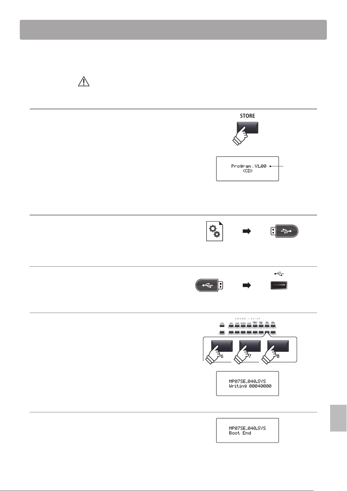
125
Appendix
This page contains instructions for updating the system software of the MP7SE, when issued by Kawai.
Please read these instructions thoroughly before attempting to perform the software update.
This update will clear any user-created SOUNDs/SETUPs stored in memory.
To retain this data, please use the AllBackup function before updating.
Checking the software version
To check the current software version installed on the MP7SE,
press and hold the STORE button, then turn the instrument ON.
The current software (Program) version will be shown on the
rst line of the LCD display.
If the Program version number is greater than or equal to the
update version, no further action is necessary.
* Turn the instrument o and on to return to normal operation.
If the Program version number is lower than the update version,
please continue to follow the instructions below.
1. Prepare the USB memory device
Extract the software update ZIP le and copy the included .SYS
les to the root folder of a USB memory device.
* USB devices should be formatted to use the ‘FAT’ or ‘FAT32’ lesystems.
2. Connect the USB memory device
While the instrument is turned o:
Connect the prepared USB memory device to the USB port.
3. Start the update
Press and hold buttons 6, 7, and 8 in the middle row of the
SOUND/SETUP section, then turn the instrument ON.
The update process will start automatically after a few seconds,
and status messages will be shown in the LCD display.
* Do not remove the USB memory device while the software update is in
progress.
4. Finish the update, disconnect the USB memory device
After approximately 60-90 seconds (depending on the number
of update les), a message will be shown in the LCD display,
indicating that the software update has been successful.
Disconnect the USB memory device, then press and hold the
POWER switch to turn the instrument OFF. When the instrument
is turned ON, the updated software will be used automatically.
* If the software update is unsuccessful, restart the process from step 1.
Software Update
hold
Program
version
hold
hold
hold
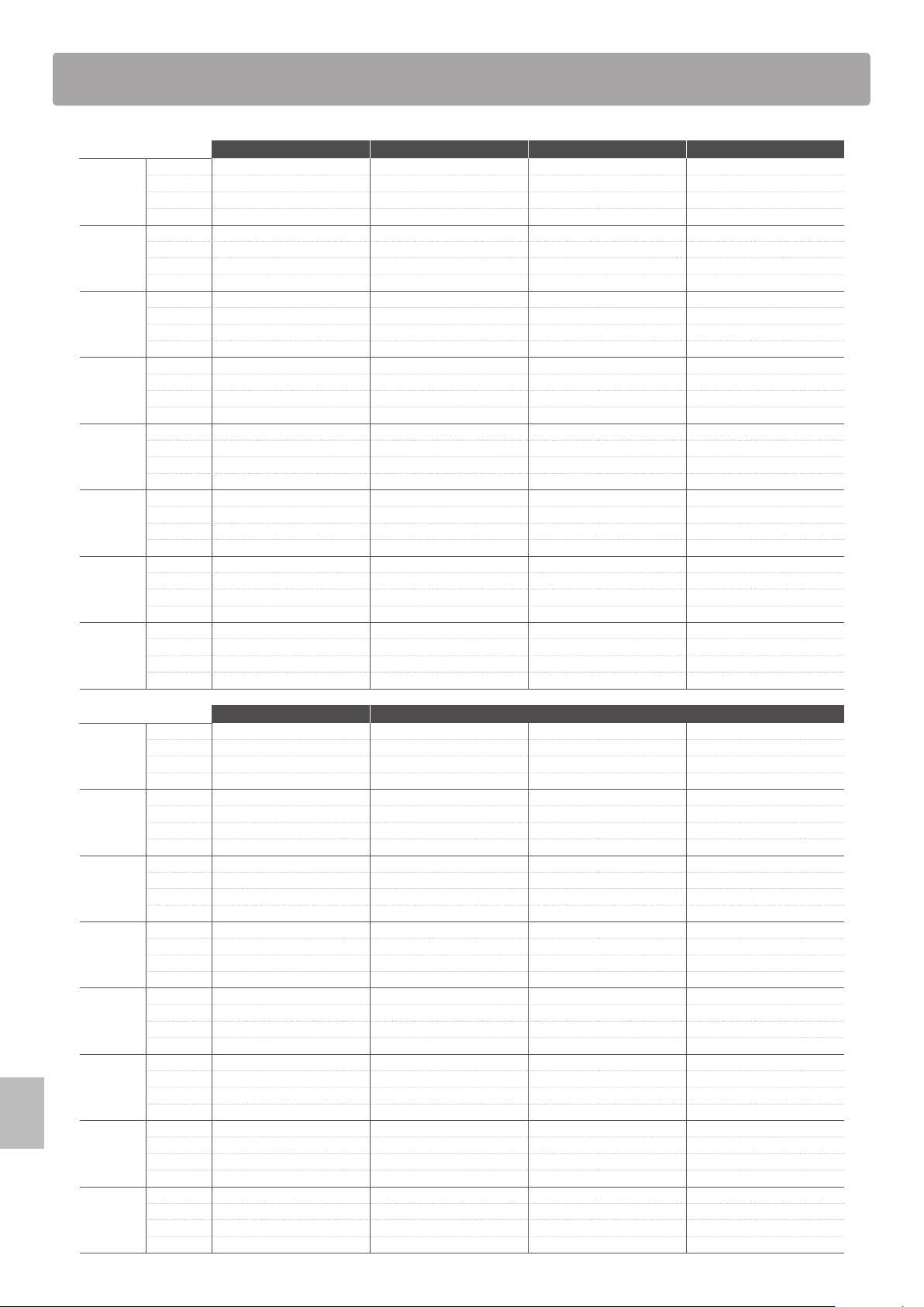
126
Appendix
PIANO E.PIANO DRAWBAR ORGAN
1
A SK Concert Grand Classic EP T.Wheel 1-A Church Organ
B SK Studio Grand Classic EP 2 T.Wheel 1-B Full Pipes
C SK Mellow Grand Classic EP 3 T.Wheel 1-C Full Ensemble
D Standard Grand Classic EP 4 T.Wheel 1-D Church Organ 2
2
A EX Concert Grand Modern EP T.Wheel 2-A PrincipleChoir
B EX Studio Grand Modern EP 2 T.Wheel 2-B Small Ensemble
C EX Mellow Grand Modern EP 3 T.Wheel 2-C Small Ens. 2
D EX Jazz Grand Modern EP 4 T.Wheel 2-D Baroque
3
A SK-5 Grand 60’s EP T.Wheel 3-A Chiy Tibia
B SK-5 StudioGrand 60’s EP 2 T.Wheel 3-B 8’&4’Principle
C SK-5 MellowGrand Electric Grand T.Wheel 3-C Stopped Pipe
D Studio Grand Electric GP 2 T.Wheel 3-D Principle Pipe
4
A Upright Piano Dolce EP Blues Organ 8’ Celeste
B Bright Upright Legend EP Drawbar Organ Diapason
C Old Upright Phase EP Drawbar Organ2 Voice Celeste
D Honky Tonk Classic EP 5 Gospel Organ Baroque Mix
5
A PopPiano Crystal EP Ballad Organ Reeds
B Bright Pop Piano New Age EP Soft Solo 8’ Reed
C Pop Piano 2 New Age EP2 Odd Man Reed Pipes
D Pop Piano 3 New Age EP3 Be Nice Posaune
6
A Modern Piano Clavinet Jazz Organ Theater Organ
B Mono SK-EX Grand Synth Clavinet Drawbar Organ3 Theater Organ2
C Mono EX Grand Clavi & Marim Perc. Organ Theater Organ3
D GM Piano Clavi Phaser Perc. Organ 2 Theater Tibia
7
A Rock Piano Vibraphone Drawbar Organ4 Elec. Organ
B Piano Oct. Celesta Full Organ Elec. Organ 2
C Piano & EP Music Box Jazzer 60’s Organ
D New Age Piano Toy Piano Jazz Organ 2 Pump Organ
8
A Harpsichord Marimba Rock Organ 2 Fr. Accordion
B Harpsichord2 Xylophone Rock Organ TangoAccordion
C Harpsi. Octave Steel Drums Drawbar Organ5 Harmonica
D Harpsi & Clavi Bells Screamin’ Kenban Harmo.
STRINGS / VOCAL BRASS / WIND PAD / SYNTH BASS / GUITAR
1
A String Pad Exp Brass Pad 1 Acc. Bass
B Warm Strings Exp Saxes Pad 2 Acc. Bass&Ride
C Warm Strings 2 Tp&Bone&Tenor Pad 3 Electric Bass
D Synth Strings Flugel & Tenor Saw Pad Electric Bass2
2
A Beautiful Str. Brass Section Pad 4 Finger Bass
B String Ens. Synth Brass Bowed Pad FingerSlapBass
C String Ens. 2 Synth Brass 2 NoisyPad Pick Bass
D Full Orchestra Jump Brass Sweep Pad Fretless Bass
3
A Small Str. Ens Exp Trumpet Saw Lead LP24 Synth Bass
B Quartet PlungerTrumpet Saw Lead LP12 Synth Bass 2
C Str. Bass Ens. Trumpet Shake Saw Lead HP Rubber Bass
D Str. Sustain Harmon Mute Tp Saw Lead BP Warm SynthBass
4
A Pizzicato Exp Trombone Square Lead LP24 Exp. Nylon Gtr
B TremoloStrings Lead Trombone Square Lead LP12 Pick Nylon Gtr
C Str. Sforzando PlungerTrombon Square Lead HP Exp Guitar
D Orchestra Hit ClosedMuteBone Square Lead BP Exp Guitar 2
5
A Passionate Vln Exp Alto Pulse Lead LP24 Rhythm Guitar
B Classic Violin Lead Alto Pulse Lead LP12 Overdrive
C Passionate Vc Soft Alto Pulse Lead HP Distortion
D Classic Cello Lead Soprano Pulse Lead BP Muted Electric
6
A Choir Exp Tenor Polysynth Pedal Steel
B Breathy Choir Ballad Tenor PolysynthOct HawaiianGuitar
C Pop Aahs Growl Tenor SqrPoly Jazz Guitar
D Slow Choir Baritone Sax Warm Lead Jazz Guitar 2
7
A Jazz Ensemble Exp Flute Oct Saw Banjo
B Female Scat Ballad Flute Oct Pulse Mandolin
C Pop Ensemble Flute Overblow Saw HPF Sitar
D Contemp Ens. Flute Flutter Sqr QTc Harp
8
A Itopia Oboe Noise UpDown Ambience Set
B Halo Pad Bassoon Noise Open Plutinum Set
C Halo Pad 2 Jazz Clarinet Resonance Voice Room Set
D Synth Vocals Pan Flute Resonance Rise Analog Set
Sound List

127
Appendix
16 Swing
1 Funk Shue 1
2 Funk Shue 2
3 Hip Hop 1
4 Hip Hop 2
5 Hip Hop 3
6 Hip Hop 4
7 16 Shue 1
8 16 Shue 2
9 16 Shue 3
16 Funk
10 Funky Beat 1
11 Funky Beat 2
12 Funky Beat 3
13 Funk 1
14 Funk 2
15 Funk 3
16 Straight
16 Jazz Funk
17 16 Beat 1
18 16 Beat 2
19 16 Beat 3
20 16 Beat 4
21 Ride Beat 4
22 Rim Beat
23 Roll Beat
24 Light Ride 1
25 Dixie Rock
16 Latin
26 Surdo Samba
27 Latin Groove
28 Light Samba
29 Songo
30 Samba
31 Merenge
16 Dance
32 Funky Beat 4
33 16 Beat 5
34 Disco 1
35 Disco 2
36 Techno 1
37 Techno 2
38 Techno 3
39 Heavy Techno
16 Ballad
40 Ballad 1
41 Ballad 2
42 Ballad 3
43 Ballad 4
44 Ballad 5
45 Light Ride 2
46 Electro Pop 1
47 Electro Pop 2
48 16 Shue 4
8 Ballad
49 Slow Jam
50 50’s Triplet
51 R&B Triplet
8 Straight
52 8 Beat 1
53 8 Beat 2
54 Smooth Beat
55 Pop 1
56 Pop 2
57 Ride Beat 1
58 Ride Beat 2
59 Ride Beat 3
60 Slip Beat
8 Rock
61 Jazz Rock
62 8 Beat 3
63 Rock Beat 1
64 Rock Beat 2
65 Rock Beat 3
66 Rock Beat 4
67 Blues/Rock
68 Heavy Beat
69 Hard Rock
70 Surf Rock
71 R&B
8 Swing
72 Motown 1
73 Fast Shue
74 Motown 2
75 Country 2 Beat
Triplet
76 Triplet Rock 1
77 Triplet Rock 2
78 Bembe
79 Rock Shue 1
80 Rock Shue 2
81 Boogie
82 Triplet 1
83 Triplet 2
84 Reggae
85 Gospel Ballad
86 Waltz
Jazz
87 H.H. Swing
88 Ride Swing
89 Fast 4 Beat
90 Afro Cuban
91 Jazz Waltz 1
92 Jazz Waltz 2
93 5/4 Swing
8 Latin
94 H.H. Bossa
95 Ride Bossa
96 Beguine
97 Mambo
98 Cha Cha
99 Tango
100 Habanera
Rhythm Pattern List
128
Appendix
EFX Categories, Types, & Parameters
1. Chorus
Variation SUB Parameter 1 Parameter 2 Parameter 3 Parameter 4 Parameter 5 Parameter 6 Parameter 7 Parameter 8 Parameter 9 Parameter 10
Stereo DryWet Speed Depth PreDly Phase LowEQ HighEQ - - -
Classic Spread Inten. LowEQ HighEQ - - - - - -
2-Band DryWet Balanc LwrSpd Lower UprSpd UprDpt PreDly SplitF - -
3-Phase DryWet Speed Depth PreDly - - - - - -
Wide DryWet Speed Depth PreDly - - - - - -
Envelope Depth Speed Sens. PreDly Phase - - - - -
Triangle
DryWet Speed Depth PreDly Phase - - - - -
Sine
DryWet Speed Depth PreDly - - - - - -
2. Flanger
Variation SUB Parameter 1 Parameter 2 Parameter 3 Parameter 4 Parameter 5 Parameter 6 Parameter 7 Parameter 8 Parameter 9 Parameter 10
Stereo DryWet Speed Depth F.Back PreDly Phase LowEQ HighEQ - -
2-Band DryWet Balanc LwrSpd Lower UprSpd UprDpt F.Back PreDly SplitF -
Touch DryWet Sens. F.Back PreDly LowEQ HighEQ - - - -
Sine
DryWet Speed Depth F.Back PreDly - - - - -
Triangle
DryWet Speed Depth F.Back PreDly Phase - - - -
3. Phaser
Variation SUB Parameter 1 Parameter 2 Parameter 3 Parameter 4 Parameter 5 Parameter 6 Parameter 7 Parameter 8 Parameter 9 Parameter 10
Warm DryWet Speed Depth Reso. LowEQ HighEQ - - - -
Classic DryWet Speed Depth Reso. Manual LowEQ HighEQ - - -
8-Stage DryWet Speed Depth Reso. Manual - - - - -
2-Band DryWet Balanc LwrSpd Lower LwrMnu UprSpd UprDpt UprMnu SplitF -
Touch DryWet Sens. Reso. Manual LowEQ HighEQ - - - -
St.2-Stage
DryWet Speed Depth Manual Phase - - - - -
4. Wah
Variation SUB Parameter 1 Parameter 2 Parameter 3 Parameter 4 Parameter 5 Parameter 6 Parameter 7 Parameter 8 Parameter 9 Parameter 10
ClasicTch DryWet Sens. Reso. Manual LowEQ HighEQ - - - -
ClassicLfo DryWet Speed Depth Reso. Manual LowEQ HighEQ - - -
ClassicPdl DryWet Sens. Reso. Manual LowEQ HighEQ - - - -
LpfTch
DryWet Sens. Manual - - - - - - -
LpfLfo
DryWet Speed Depth Manual - - - - - -
LpfPdl
DryWet Sens. Manual - - - - - - -
5. Tremolo
Variation SUB Parameter 1 Parameter 2 Parameter 3 Parameter 4 Parameter 5 Parameter 6 Parameter 7 Parameter 8 Parameter 9 Parameter 10
Classic Depth Speed LowEQ HighEQ - - - - - -
2-Band Depth Balanc LwrSpd UprSpd SplitF - - - - -
VibratoTrm Depth Speed Vib. LowEQ HighEQ - - - - -
Sine
Depth Speed - - - - - - - -
Square
Depth Speed - - - - - - - -
Saw
Depth Speed - - - - - - - -
129
Appendix
EFX Categories, Types, & Parameters
6. Auto Pan
Variation SUB Parameter 1 Parameter 2 Parameter 3 Parameter 4 Parameter 5 Parameter 6 Parameter 7 Parameter 8 Parameter 9 Parameter 10
Classic Depth Speed LowEQ HighEQ - - - - - -
2-Band Depth Balanc LwrSpd UprSpd SplitF - - - - -
Envelope Depth Speed Sens. - - - - - - -
Standard
Depth Speed - - - - - - - -
7. Delay / Reverb
Variation SUB Parameter 1 Parameter 2 Parameter 3 Parameter 4 Parameter 5 Parameter 6 Parameter 7 Parameter 8 Parameter 9 Parameter 10
Standard DryWet Time F.Back H.Damp - - - - - -
PingPong DryWet Time F.Back H.Damp - - - - - -
LCR DryWet Time F.Back H.Damp - - - - - -
3-Tap DryWet C.Time C.Gain F.Back H.Damp L.Time L.Gain R.Time RightG -
Classic
DryWet Time F.Back - - - - - - -
Short
DryWet Time F.Back - - - - - - -
Ambience DryWet Size H.Damp LowEQ HighEQ - - - - -
EarlyRef DryWet Size PreDly LPF LowEQ HighEQ - - - -
8. Pitch Shift
Variation SUB Parameter 1 Parameter 2 Parameter 3 Parameter 4 Parameter 5 Parameter 6 Parameter 7 Parameter 8 Parameter 9 Parameter 10
Detune DryWet Fine - - - - - - - -
FeedBack DryWet Fine Coarse Delay F.Back H.Damp - - - -
Standard
DryWet Fine Coarse - - - - - - -
9. Compressor
Variation SUB Parameter 1 Parameter 2 Parameter 3 Parameter 4 Parameter 5 Parameter 6 Parameter 7 Parameter 8 Parameter 9 Parameter 10
2-Band Gain Balanc LRatio LThrsh LwrAtk Releas URatio UThrsh UprAtk SplitF
Standard
Gain Ratio Trshld Attack Releas - - - - -
10. Overdrive
Variation SUB Parameter 1 Parameter 2 Parameter 3 Parameter 4 Parameter 5 Parameter 6 Parameter 7 Parameter 8 Parameter 9 Parameter 10
Stereo DryWet Drive Gain LowEQ HighEQ - - - - -
Classic
DryWet Drive Gain - - - - - - -
Distortion
DryWet Drive Gain - - - - - - -
11. EQ / Filter
Variation SUB Parameter 1 Parameter 2 Parameter 3 Parameter 4 Parameter 5 Parameter 6 Parameter 7 Parameter 8 Parameter 9 Parameter 10
4-BandEQ Gain Low Mid1 Mid1Q Mid1F High Mid2 Mid2Q Mid2F -
7-BandEQ Gain 100Hz 200Hz 400Hz 800Hz 1.6kHz 3.2kHz 6.4kHz - -
Standard
Gain Low Mid High Mid F - - - - -
Enhancer
DryWet Depth - - - - - - - -
10-PoleFlt DryWet Freq. Sens. Gain LpfHpf - - - - -
130
Appendix
EFX Categories, Types, & Parameters
12. Rotary
Variation SUB Parameter 1 Parameter 2 Parameter 3 Parameter 4 Parameter 5 Parameter 6 Parameter 7 Parameter 8 Parameter 9 Parameter 10
Classic Slow/Fast LwrFastSpd LwrSlowSpd LwrAcc.Spd Rot:Spread UprFastSpd UprSlowSpd UprAcc.Spd - -
Warm Slow/Fast LwrFastSpd LwrSlowSpd LwrAcc.Spd Rot:Spread UprFastSpd UprSlowSpd UprAcc.Spd - -
Dirty Slow/Fast Rot:Depth Rot:AccSpd Rot:Spread FastSpeed SlowSpeed Rot:LowEQ Rot:HighEQ Rot:Drive Rot:Gain
+Vib/Cho Slow/Fast Rot:Depth FastSpeed SlowSpeed Rot:AccSpd Rot:Spread Rot:VibCho Rot:Mode - -
Single
Slow/Fast Rot:Depth FastSpeed SlowSpeed Rot:AccSpd Rot:Spread - - - -
13. Groove
Variation
SUB
Parameter 1 Parameter 2 Parameter 3 Parameter 4 Parameter 5 Parameter 6 Parameter 7 Parameter 8 Parameter 9 Parameter 10
S/H Flg Grv:DryWet Grv:Speed Grv:Depth Grv:F.Back Grv:Manual Grv:Attack Grv:PanDpt - - -
S/H Pha Grv:DryWet Grv:Speed Grv:Depth Grv:F.Back Grv:Manual Grv:Attack Grv:PanDpt - - -
S/H Wah Grv:DryWet Grv:Speed Grv:Depth Grv:F.Back Grv:Manual Grv:Attack Grv:PanDpt - - -
S/H Pan
Grv:DryWet Grv:Speed Grv:Pan Grv:Attack - - - - - -
14. Misc
Variation
SUB
Parameter 1 Parameter 2 Parameter 3 Parameter 4 Parameter 5 Parameter 6 Parameter 7 Parameter 8 Parameter 9 Parameter 10
RingMod Mod:DryWet Mod:Freq. Mod:LowEQ Mod:HighEQ - - - - - -
Lo-Fi Mod:DryWet Mod:ModSpd Mod:ModDpt Mod:S.Rate Mod:Reso. Mod:Filter - - - -
15. Chorus+
main zone only
Variation Parameter 1 Parameter 2 Parameter 3 Parameter 4 Parameter 5 Parameter 6 Parameter 7 Parameter 8 Parameter 9 Parameter 10
Flanger Cho:DryWet Cho:Speed Cho:Depth Cho:PreDly Cho:Phase Flg:DryWet Flg:Speed Flg:Depth Flg:F.Back Flg:PreDly
Phaser Cho:DryWet Cho:Speed Cho:Depth Cho:PreDly Cho:Phase Pha:DryWet Pha:Speed Pha:Depth Pha:Manual Pha:Phase
Wah Cho:DryWet Cho:Speed Cho:Depth Cho:PreDly Cho:Phase Wah:DryWet Wah:Sens. Wah:Manual - -
Tremolo Cho:DryWet Cho:Speed Cho:Depth Cho:PreDly Cho:Phase Trm:Depth Trm:Speed - - -
AutoPan Cho:DryWet Cho:Speed Cho:Depth Cho:PreDly Cho:Phase Pan:Depth Pan:Speed - - -
Delay Cho:DryWet Cho:Speed Cho:Depth Cho:PreDly Cho:Phase Dly:DryWet Dly:Time Dly:F.Back - -
16. Phaser+
main zone only
Variation Parameter 1 Parameter 2 Parameter 3 Parameter 4 Parameter 5 Parameter 6 Parameter 7 Parameter 8 Parameter 9 Parameter 10
Chorus Pha:DryWet Pha:Speed Pha:Depth Pha:Manual Pha:Phase Cho:DryWet Cho:Speed Cho:Depth Cho:PreDly Cho:Phase
Flanger Pha:DryWet Pha:Speed Pha:Depth Pha:Manual Pha:Phase Flg:DryWet Flg:Speed Flg:Depth Flg:F.Back Flg:PreDly
Wah Pha:DryWet Pha:Speed Pha:Depth Pha:Manual Pha:Phase Wah:DryWet Wah:Sens. Wah:Manual - -
Tremolo Pha:DryWet Pha:Speed Pha:Depth Pha:Manual Pha:Phase Trm:Depth Trm:Speed - - -
AutoPan Pha:DryWet Pha:Speed Pha:Depth Pha:Manual Pha:Phase Pan:Depth Pan:Speed - - -
Delay Pha:DryWet Pha:Speed Pha:Depth Pha:Manual Pha:Phase Dly:DryWet Dly:Time Dly:F.Back - -
131
Appendix
EFX Categories, Types, & Parameters
17. Wah+
main zone only
Variation Parameter 1 Parameter 2 Parameter 3 Parameter 4 Parameter 5 Parameter 6 Parameter 7 Parameter 8 Parameter 9 Parameter 10
Chorus Wah:DryWet Wah:Sens. Wah:Manual Cho:DryWet Cho:Speed Cho:Depth Cho:PreDly Cho:Phase - -
Flanger Wah:DryWet Wah:Sens. Wah:Manual Flg:DryWet Flg:Speed Flg:Depth Flg:F.Back Flg:PreDly - -
Phaser Wah:DryWet Wah:Sens. Wah:Manual Pha:DryWet Pha:Speed Pha:Depth Pha:Manual Pha:Phase - -
Tremolo Wah:DryWet Wah:Sens. Wah:Manual Trm:Depth Trm:Speed - - - - -
AutoPan Wah:DryWet Wah:Sens. Wah:Manual Pan:Depth Pan:Speed - - - - -
Delay Wah:DryWet Wah:Sens. Wah:Manual Dly:DryWet Dly:Time Dly:F.Back - - - -
18. EQ+
main zone only
Variation Parameter 1 Parameter 2 Parameter 3 Parameter 4 Parameter 5 Parameter 6 Parameter 7 Parameter 8 Parameter 9 Parameter 10
Chorus EQ :Gain EQ :Low EQ :Mid EQ :High EQ :Mid F Cho:DryWet Cho:Speed Cho:Depth Cho:PreDly Cho:Phase
Flanger EQ :Gain EQ :Low EQ :Mid EQ :High EQ :Mid F Flg:DryWet Flg:Speed Flg:Depth Flg:F.Back Flg:PreDly
Phaser EQ :Gain EQ :Low EQ :Mid EQ :High EQ :Mid F Pha:DryWet Pha:Speed Pha:Depth Pha:Manual Pha:Phase
Wah EQ :Gain EQ :Low EQ :Mid EQ :High EQ :Mid F Wah:DryWet Wah:Sens. Wah:Manual - -
Tremolo EQ :Gain EQ :Low EQ :Mid EQ :High EQ :Mid F Trm:Depth Trm:Speed - - -
AutoPan EQ :Gain EQ :Low EQ :Mid EQ :High EQ :Mid F Pan:Depth Pan:Speed - - -
Delay EQ :Gain EQ :Low EQ :Mid EQ :High EQ :Mid F Dly:DryWet Dly:Time Dly:F.Back - -
Compressor EQ :Gain EQ :Low EQ :Mid EQ :High EQ :Mid F Cmp:Gain Cmp:Ratio Cmp:Thresh Cmp:Attack Cmp:Releas
19. Enhancer+
main zone only
Variation Parameter 1 Parameter 2 Parameter 3 Parameter 4 Parameter 5 Parameter 6 Parameter 7 Parameter 8 Parameter 9 Parameter 10
Chorus Enh:DryWet Enh:Depth Cho:DryWet Cho:Speed Cho:Depth Cho:PreDly Cho:Phase - - -
Flanger Enh:DryWet Enh:Depth Flg:DryWet Flg:Speed Flg:Depth Flg:F.Back Flg:PreDly - - -
Phaser Enh:DryWet Enh:Depth Pha:DryWet Pha:Speed Pha:Depth Pha:Manual Pha:Phase - - -
Wah Enh:DryWet Enh:Depth Wah:DryWet Wah:Sens. Wah:Manual - - - - -
Tremolo Enh:DryWet Enh:Depth Trm:Depth Trm:Speed - - - - - -
AutoPan Enh:DryWet Enh:Depth Pan:Depth Pan:Speed - - - - - -
Delay Enh:DryWet Enh:Depth Dly:DryWet Dly:Time Dly:F.Back - - - - -
Compressor Enh:DryWet Enh:Depth Cmp:Gain Cmp:Ratio Cmp:Thresh Cmp:Attack Cmp:Releas - - -
20. Pitch Shift+
main zone only
Variation Parameter 1 Parameter 2 Parameter 3 Parameter 4 Parameter 5 Parameter 6 Parameter 7 Parameter 8 Parameter 9 Parameter 10
Flanger Psh:DryWet Psh:Fine Psh:Coarse Flg:DryWet Flg:Speed Flg:Depth Flg:F.Back Flg:PreDly - -
Phaser Psh:DryWet Psh:Fine Psh:Coarse Pha:DryWet Pha:Speed Pha:Depth Pha:Manual Pha:Phase - -
Wah Psh:DryWet Psh:Fine Psh:Coarse Wah:DryWet Wah:Sens. Wah:Manual - - - -
Tremolo Psh:DryWet Psh:Fine Psh:Coarse Trm:Depth Trm:Speed - - - - -
AutoPan Psh:DryWet Psh:Fine Psh:Coarse Pan:Depth Pan:Speed - - - - -
Delay Psh:DryWet Psh:Fine Psh:Coarse Dly:DryWet Dly:Time Dly:F.Back - - - -
132
Appendix
EFX Categories, Types, & Parameters
21. Compressor+
main zone only
Variation Parameter 1 Parameter 2 Parameter 3 Parameter 4 Parameter 5 Parameter 6 Parameter 7 Parameter 8 Parameter 9 Parameter 10
Chorus Cmp:Gain Cmp:Ratio Cmp:Thresh Cmp:Attack Cmp:Releas Cho:DryWet Cho:Speed Cho:Depth Cho:PreDly Cho:Phase
Flanger Cmp:Gain Cmp:Ratio Cmp:Thresh Cmp:Attack Cmp:Releas Flg:DryWet Flg:Speed Flg:Depth Flg:F.Back Flg:PreDly
Phaser Cmp:Gain Cmp:Ratio Cmp:Thresh Cmp:Attack Cmp:Releas Pha:DryWet Pha:Speed Pha:Depth Pha:Manual Pha:Phase
Wah Cmp:Gain Cmp:Ratio Cmp:Thresh Cmp:Attack Cmp:Releas Wah:DryWet Wah:Sens. Wah:Manual - -
Tremolo Cmp:Gain Cmp:Ratio Cmp:Thresh Cmp:Attack Cmp:Releas Trm:Depth Trm:Speed - - -
AutoPan Cmp:Gain Cmp:Ratio Cmp:Thresh Cmp:Attack Cmp:Releas Pan:Depth Pan:Speed - - -
Delay Cmp:Gain Cmp:Ratio Cmp:Thresh Cmp:Attack Cmp:Releas Dly:DryWet Dly:Time Dly:F.Back - -
OverDrive Cmp:Gain Cmp:Ratio Cmp:Thresh Cmp:Attack Cmp:Releas Ovd:DryWet Ovd:Drive Ovd:Gain - -
22. Overdrive+
main zone only
Variation Parameter 1 Parameter 2 Parameter 3 Parameter 4 Parameter 5 Parameter 6 Parameter 7 Parameter 8 Parameter 9 Parameter 10
Chorus Ovd:DryWet Ovd:Drive Ovd:Gain Cho:DryWet Cho:Speed Cho:Depth Cho:PreDly Cho:Phase - -
Flanger Ovd:DryWet Ovd:Drive Ovd:Gain Flg:DryWet Flg:Speed Flg:Depth Flg:F.Back Flg:PreDly - -
Phaser Ovd:DryWet Ovd:Drive Ovd:Gain Pha:DryWet Pha:Speed Pha:Depth Pha:Manual Pha:Phase - -
Wah Ovd:DryWet Ovd:Drive Ovd:Gain Wah:DryWet Wah:Sens. Wah:Manual - - - -
Tremolo Ovd:DryWet Ovd:Drive Ovd:Gain Trm:Depth Trm:Speed - - - - -
AutoPan Ovd:DryWet Ovd:Drive Ovd:Gain Pan:Depth Pan:Speed - - - - -
Delay Ovd:DryWet Ovd:Drive Ovd:Gain Dly:DryWet Dly:Time Dly:F.Back - - - -
EQ Ovd:DryWet Ovd:Drive Ovd:Gain EQ :Gain EQ :Low EQ :Mid EQ :High EQ :MidFrq - -
23. Parallel
main zone only
Variation Parameter 1 Parameter 2 Parameter 3 Parameter 4 Parameter 5 Parameter 6 Parameter 7 Parameter 8 Parameter 9 Parameter 10
Cho ll Flg Cho:DryWet Cho:Speed Cho:Depth Cho:PreDly Cho:Phase Flg:DryWet Flg:Speed Flg:Depth Flg:F.Back Flg:PreDly
Cho ll Pha Cho:DryWet Cho:Speed Cho:Depth Cho:PreDly Cho:Phase Pha:DryWet Pha:Speed Pha:Depth Pha:Manual Pha:Phase
Cho ll Wah Cho:DryWet Cho:Speed Cho:Depth Cho:PreDly Cho:Phase Wah:DryWet Wah:Sens. Wah:Manual - -
Cho ll Trm Cho:DryWet Cho:Speed Cho:Depth Cho:PreDly Cho:Phase Trm:Depth Trm:Speed - - -
Cho ll Pan Cho:DryWet Cho:Speed Cho:Depth Cho:PreDly Cho:Phase Pan:Depth Pan:Speed - - -
Cho ll Dly Cho:DryWet Cho:Speed Cho:Depth Cho:PreDly Cho:Phase Dly:DryWet Dly:Time Dly:F.Back - -
133
Appendix
Kawai MP7SE Stage Piano
Keyboard 88 weighted keys with Ivory Touch key surfaces
Responsive Hammer III (RH III) action with Let-O, Triple Sensor, and Counterweights
Sound Source Harmonic Imaging™ XL (HI-XL), 88-key piano sampling
No. of Sounds 256 voices
(8 categories)
PIANO x 32, E.PIANO x 32, DRAWBAR x 32, ORGAN x 32, STRINGS/VOCAL x 32,
BRASS/WIND x32, PAD/SYNTH x 32, BASS/GUITAR x 32
Polyphony max. 256 notes
Zones Types: MAIN, SUB1, SUB2, SUB3
Modes: INT, EXT, BOTH
Reverb Types: 6 types (Room, Lounge, Small Hall, Concert Hall, Live Hall, Cathedral)
Parameters: PreDelay, Reverb Time, Reverb Depth
Eects Types: 129 types (MAIN zone), 22 types (SUB zones)
Parameters: Up to 10 parameters, depending on eect type
Modules: MAIN zone: EFX1, EFX2 SUB zones: EFX
Amp Simulator
main zone only
Types: 5 types (S. Case, M. Stack, J. Combo, F. Bass, L. Cabi)
Parameters: Drive, Level, Amp EQ Lo, Amp EQ Mid, Amp EQ Hi, Mid Frequency,
Mic Type, Mic Position, Ambience
Tonewheel Organ
main zone only
Drawbars: 16’, 5 ⁄’, 8’, 4’, 2 ⁄’, 2’, 1 ⁄’, 1 ⁄’, 1’ (real-time adjustable by panel faders/knobs and MIDI)
Percussion: O/On, Normal/Soft, Slow/Fast, 2nd/3rd
Virtual Technician Touch Curve: 6 types (Light+, Light, Normal, Heavy, Heavy+, O), User1~5
Parameters:
piano: Voicing, String Resonance, Undamped Resonance, Damper Resonance, Key-o Eect,
Damper Noise, Hammer Delay, Fall-back Noise, Topboard, Stereo Width
e.piano/harpsi/bass: Key-o Noise, Key-o Delay
drawbar: Key Click Level, Wheel Noise Level
Temperament
& Tuning:
7 types (Equal, Pure Major/Minor, Pythagorean, Meantone, Werkmeister, Kirnberger), User1~2
Fine Tune, Stretch Tuning, Key of Temperament
EQ 4-band equaliser (Low Gain, Mid1 Gain, Mid1 Q, Mid1 Freq., Mid2 Gain, Mid2 Q, Mid2 Freq., High Gain)
Recorder Internal: 10 songs – approximately 90,000 note memory capacity
Transpose song, Convert song to Audio, Load SMF, Save SMF
Audio: Play MP3/WAV, Save MP3/WAV, Overdub, Recorder Gain
Metronome Click: 1/4, 2/4, 3/4, 4/4, 5/4, 3/8, 6/8, 7/8, 9/8, 12/8
Rhythm: 100 drum patterns
Internal Memories SOUND: 256 memories (8 x 8 x 4)
SETUP: 256 memories (8 x 8 x 4)
POWERON: 1 memory
USB Functions Load/Save: One Sound, One Setup, SMF, All Sound, All Setup, All Backup
Others: Delete, Rename, Format
EDIT Menu INT mode: 116 parameters (Reverb, EFX/AMP, Sound, Tuning, Key Setup, Controllers, Knob Assign, Virtual Tech.)
EXT mode: 64 parameters (Channel/Program, SETUP, Transmit, MMC, Key Setup, Controllers, Knob Assign)
SYSTEM Menu 52 parameters and functions (Utility, Pedal, MIDI, Oset, User Edit, Reset)
Display 128 x 64 pixel LCD with backlight
Panel Controls Pitch Bend, Modulation, SW1, SW2, Volume, Line In, Zone Mixer, Control Knobs A~D (assignable), MMC
Jacks Output: 1/4” LINE OUT (L/MONO, R), Headphones
Input: 1/4” LINE IN (L/MONO, R)
MIDI & USB: MIDI IN, MIDI OUT, MIDI THRU, USB to Host, USB to Device
Foot Control: DAMPER (for F-10H), DAMPER/SOSTENUTO/SOFT (for GFP-3), FSW, EXP with EXP TYPE switch
Power: AC IN
Power Consumption 20 W
Dimensions 1362 (W) x 339 (D) x 172 (H) mm / 53 ⁄” (W) x 13 ⁄” (D) x 6 ¾” (H)
Weight 22.5 kg / 49.6 lbs.
Included Accessories F-10H pedal unit (with half-damper support), Music rest, Power cable, Owner’s manual
Specications are subject to change without notice.
Specications

134
Appendix
Contents
1. Recognised data
1.1 Channel Voice Message
1.2 Channel Mode Message
1.3 System Realtime Message
2. Transmitted data
2.1 Channel Voice Message
2.2 Channel Mode Message
2.3 System Realtime Message
3. Exclusive data
3.1 MMC Commands
3.2 Parameter Send
3.3 Setup Parameters: Global Section
3.4 Setup Parameters: EDIT Menu
3.5 Setup Parameters: SYSTEM Menu
3.6 Assignable Knob Parameters
4. SOUND/SETUP Program/Bank
4.1 SETUP Program Number Table
5. Program Change Number List
6. Control Change Number (CC#) Table
MIDI Implementation Chart
Version 1.0 (June 2017)
MIDI Implementation

135
Appendix
MIDI Implementation
1
Recognised Data
1.1 Channel Voice Message
Note o
Status 2nd Byte 3rd Byte
8nH kkH vvH
9nH kkH 00H
n=MIDI channel number :0H-fH(ch.1 ~ ch.16)
kk=Note Number :00H - 7fH(0 ~ 127)
vv=Velocity :00H - 7fH(0 ~ 127)
Note on
Status 2nd Byte 3rd Byte
9nH kkH vvH
n=MIDI channel number :0H-fH(ch.1 ~ ch.16)
kk=Note Number :00H - 7fH(0 ~ 127)
vv=Velocity :00H - 7fH(0 ~ 127)
Control Change Bank Select (MSB)
Status 2nd Byte 3rd Byte
BnH 00H mmH
BnH 20H llH
n=MIDI channel number :0H-fH(ch.1 ~ ch.16)
mm = Bank Number MSB :00H-7fH (0 ~ 127)
ll = BankNumber LSB :00H-7fH (0 ~ 127)
Modulation
Status 2nd Byte 3rd Byte
BnH 01H vvH
n=MIDI channel number :0H-fH(ch.1 ~ ch.16)
vv = Modulation depth :00H - 7fH(0 ~ 127) Default = 00H
Data Entry
Status 2nd Byte 3rd Byte
BnH 06H mmH
BnH 26H llH
n=MIDI channel number :0H-fH(ch.1 ~ ch.16)
mm,ll= Value indicated in RPN/NRPN :00H - 7fH(0 ~ 127)
*see RPN/NRPN chapter
Volume
Status 2nd Byte 3rd Byte
BnH 07H vvH
n=MIDI channel number :0H-fH(ch.1 ~ ch.16)
vv=Volume :00H - 7fH(0 ~ 127) Default = 7fH
Panpot
Status 2nd Byte 3rd Byte
BnH 0aH vvH
n=MIDI channel number :0H-fH(ch.1 - ch.16)
vv=Panpot :00H - 40H - 7fH(left ~centre~right) Default = 40H(centre)

136
Appendix
1.1 Channel Voice Message (cont.)
Expression
Status 2nd Byte 3rd Byte
BnH 0bH vvH
n=MIDI channel number :0H-fH(ch.1 - ch.16)
vv=Expression :00H - 7fH(0 - 127) Default = 7fH
Damper Pedal
Status 2nd Byte 3rd Byte
BnH 40H vvH
n=MIDI channel number :0H-fH(ch.1 ~ ch.16)
vv=Control Value :00H - 7fH(0 ~ 127) Default = 00H
0 - 63=OFF, 64 - 127=ON
Sostenuto Pedal
Status 2nd Byte 3rd Byte
BnH 42H vvH
n=MIDI channel number :0H-fH(ch.1 ~ ch.16)
vv=Control Value :00H - 7fH(0 ~ 127) Default = 00H
0 - 63 =OFF, 64 - 127=ON
Soft Pedal
Status 2nd Byte 3rd Byte
BnH 43H vvH
n=MIDI channel number :0H-fH(ch.1 ~ ch.16)
vv=Control Value :00H - 7fH(0 ~ 127) Default = 00H
0 - 63 =OFF, 64 - 127=ON
Sound controllers #1-9
Status 2nd Byte 3rd Byte
BnH 46H vvH Sustain Level
BnH 47H vvH Resonance
BnH 48H vvH Release time
BnH 49H vvH Attack time
BnH 4aH vvH Cuto
BnH 4bH vvH Decay time
BnH 4cH vvH Vibrato Rate
BnH 4dH vvH Vibrato Depth
BnH 4eH vvH Vibrato Delay
n=MIDI channel number :0H-fH(ch.1 ~ ch.16)
vv=Control Value :00H - 7fH(-64 ~ 0 ~ +63) Default = 40H
Eect Control
Status 2nd Byte 3rd Byte
BnH 5bH vvH Reverb depth
n=MIDI channel number :0H-fH(ch.1 ~ ch.16)
vv = Control Value :00H - 7fH(0 ~ 127)
MIDI Implementation

137
Appendix
MIDI Implementation
1.1 Channel Voice Message (cont.)
RPN MSB/LSB
Status 2nd Byte 3rd Byte
BnH 63H mmH
BnH 62H llH
n=MIDI channel number :0H-fH(ch.1 ~ ch.16)
mm=MSB of the NRPN parameter number
ll=LSB of the NRPN parameter number
NRPN numbers implemented in MP7SE are as follows
NRPN # Data
MSB LSB MSB Function & Range
01H 08H mmH Vibrato Rate mm :00H - 7FH(-64 ~ 0 ~ +63) Default = 40H
01H 09H mmH Vibrato Depth mm :00H - 7FH(-64 ~ 0 ~ +63) Default = 40H
01H 0aH mmH Vibrato Delay mm :00H - 7FH(-64 ~ 0 ~ +63) Default = 40H
01H 20H mmH Cuto mm :00H - 7FH(-64 ~ 0 ~ +63) Default = 40H
01H 21H mmH Resonance mm :00H - 7FH(-64 ~ 0 ~ +63) Default = 40H
01H 63H mmH Attack time mm :00H - 7FH(-64 ~ 0 ~ +63) Default = 40H
01H 64H mmH Decay time mm :00H - 7FH(-64 ~ 0 ~ +63) Default = 40H
01H 66H mmH Release time mm :00H - 7FH(-64 ~ 0 ~ +63) Default = 40H
* Ignoring the LSB of data Entry
* It is not aected in case of modifying cuto if tone does not use the DCF.
RPN MSB/LSB
Status 2nd Byte 3rd Byte
BnH 65H mmH
BnH 64H llH
n=MIDI channel number :0H-fH(ch.1 ~ ch.16)
mm=MSB of the RPN parameter number
ll=LSB of the RPN parameter number
RPN number implemented in MP7SE are the followings
RPN # Data
MSB LSB MSB LSB Function & Range
00H 00H mmH llH Pitch bend sensitivity
mm :00H-0cH (0~12 [half tone]),ll:00H Default = 02H
00H 01H mmH llH Master ne tuning
mm,ll :20 00H - 40 00H - 60 00H (-8192x50/8192 ~ 0 ~ +8192x50/8192 [cents])
00H 05H mmH llH Modulation Depth Range Default = 00H/40H (+/-50 cents)
mm,ll :00 00H - 06 00H (0~600[cents])
7fH 7fH -- -- RPN NULL
Program Change
Status 2nd Byte
CnH ppH
n=MIDI channel number :0H-fH(ch.1 ~ ch.16)
pp=Program number :00H - 7fH(0 ~- 127) Default = 00H
Pitch Bend Change
Status 2nd Byte 3rd Byte
EnH llH mmH
n=MIDI channel number :0H-fH(ch.1 ~ ch.16)
mm,ll=Pitch bend value :00 00-7f 7fH(-8192~0~+8192) Default = 40 00H

138
Appendix
1.2 Channel Mode Message
All Sound OFF
Status 2nd Byte 3rd Byte
BnH 78H 00H
n=MIDI channel number :0H-fH(ch.1 ~ ch.16)
Reset All Controller
Status 2nd Byte 3rd Byte
BnH 79H 00H
n=MIDI channel number :0H-fH(ch.1 ~ ch.16)
All Note O
Status 2nd Byte 3rd Byte
BnH 7bH 00H
n=MIDI channel number :0H-fH(ch.1 ~ ch.16)
1.3 System Realtime Message
Status
FEH Active sensing
MIDI Implementation

139
Appendix
MIDI Implementation
2
Transmitted Data
2.1 Channel Voice Message
Note o
Status 2nd Byte 3rd Byte
8nH kkH vvH
n=MIDI channel number :0H-fH(ch.1 ~ ch.16)
kk=Note Number :00H - 7fH(0 ~ 127)
vv=Velocity :00H - 7fH(0 ~ 127)
Note on
Status 2nd Byte 3rd Byte
9nH kkH vvH
n=MIDI channel number :0H-fH(ch.1 ~ ch.16)
kk=Note Number :00H - 7fH(0 ~ 127)
vv=Velocity :00H - 7fH(0 ~ 127)
Control Change
Status 2nd Byte 3rd Byte
BnH ccH vvH
* Sending by Assignable Control Knobs
Program Change
Status 2nd Byte
CnH ppH
n=MIDI channel number :0H-fH(ch.1 ~ ch.16)
pp=Program number :00H - 7fH(0 ~- 127) Default = 00H
After Touch
Status 2nd Byte
DnH ppH
n=MIDI channel number :0H-fH(ch.1 ~ ch.16)
pp=Value
*Sending only when Controller or Knob=AfterTouch
Pitch Bend Change
Status 2nd Byte 3rd Byte
EnH llH mmH
n=MIDI channel number :0H-fH(ch.1 ~ ch.16)
mm,ll=Pitch bend value :00 00-7f 7fH(-8192~0~+8192) Default = 40 00H

140
Appendix
2.2 Channel Mode Message
Reset All Controller
Status 2nd Byte 3rd Byte
BnH 79H 00H
n = MIDI channel number :0H-fH(ch.1 ~ ch.16)
*Sending by [PANIC] function
All Note O
Status 2nd Byte 3rd Byte
BnH 7bH 00H
n = MIDI channel number :0H-fH(ch.1 ~ ch.16)
*Sending by [PANIC] function
MONO
Status 2nd Byte 3rd Byte
BnH 7eH mmH
n=MIDI channel number :0H-fH(ch.1 ~ ch.16)
mm=mono number :01H(M=1)
POLY
Status 2nd Byte 3rd Byte
BnH 7fH 00H
n=MIDI channel number :0H-fH(ch.1 ~ ch.16)
2.3 System Realtime Message
Status
FAH Start
FBH Continue
FCH Stop
*Sending by [RECORDER CONTROL] buttons
MIDI Implementation
141
Appendix
MIDI Implementation
3
Exclusive Data
3.1 MMC Commands
No. Description Value Notes
1 Exclusive F0H
2 Universal Real Time 7FH
3 Device ID 0-7FH
4 MMC command 06H
5 Command Number 01-0DH * see table right
6 EOX F7H
*Sending by [RECORDER CONTROL] buttons
* Transmit only
MMC Commands
01 STOP 08 RECORD PAUSE
02 PLAY 09 PAUSE
03 DEFERRED PLAY 0A EJECT
04 FAST FORWARD 0B CHASE
05 REWIND 0C COMMAND ERROR RESET
06 RECORD STROBE 0D MMC RESET
07 RECORD EXIT
3.2 Parameter Send
No. Description Value Notes
1 Exclusive F0H
2 KAWAI ID 40H
3 Channel no. 0-0FH,7FH System Channel = 0-FH, Global = 7FH
4 Function no. 10H Parameter Send
5 Group no. 00H MI Group ID
6 Machine no. 13H Machine ID
7 data1 50-5FH Command ID
8 data2 0-7FH Sub Command ID
9 data3 0-7FH Part number (System = 7FH)
10 data4~ 0-7FH data max 18byte
EOX F7H
Part number :
MP7SE *pp=00~07
00H INT1 (MAIN)
01H INT2 (SUB1)
02H INT3 (SUB3)
03H INT4 (SUB3)
04H EXT1 (MAIN)
05H EXT2 (SUB1)
06H EXT3 (SUB2)
07H EXT4 (SUB3)
08H -reserved-
09H INT-COMMON
0AH EXT-COMMON
7FH SYSTEM/COMMON
142
Appendix
MIDI Implementation
3.3 Setup Parameters: Global Section
Category Parameter Com. Sub. Part Byte Value (HEX)
SETUP Setup Mode On/O 51 04 7F 1 00, 01 (O, On)
SETUP Bank/Variation 51 05 7F 2 Bank=00~3F (1-1~8-8) /Vari.=00~03 (A~D)
GLOBAL Global EQ Switch 51 10 7F 1 00, 01 (O, On)
Global EQ Low Gain 51 11 7F 1 36~40~4A (-10 ~ +0 ~ +10dB)
Global EQ High Gain 51 12 7F 1 36~40~4A (-10 ~ +0 ~ +10dB)
Global EQ Mid1 Gain 51 13 7F 1 36~40~4A (-10 ~ +0 ~ +10dB)
Global EQ Mid2 Gain 51 14 7F 1 36~40~4A (-10 ~ +0 ~ +10dB)
Global EQ Mid1 Q 51 17 7F 1 00~06 (0.5~4.0)
Global EQ Mid2 Q 51 18 7F 1 00~06 (0.5~4.0)
Global EQ Mid1 Frequency 51 15 7F 1 00~7F (200~3150Hz)
Global EQ Mid2 Frequency 51 16 7F 1 00~7F (200~3150Hz)
Transpose Switch 53 01 7F 1 00, 01 (O, On)
Transpose Value 53 02 7F 1 28~40~58 (-24~0~+24)
LocalO 58 01 7F 1 00, 01 (LocalO, LocalOn)
Metornome Mode 56 0A 7F 1 00, 01 (Click, Rhythm)
Metronome Beat 56 02 7F 2 01~16 (Beat) /01, 02, 03, 04 (Measure: 1/2, 1/4, 1/8, 1/16)
Metornome Volume 56 03 7F 1 00~7F (0~127)
Metronome Tempo 56 01 7F 2 TempoMSB/TempoLSB=00/1E~02/2C (30~300)
Rhythm Category 56 09 7F 1 Rhythm Pattern=00~63(1~100)
Rhythm Variation 56 09 7F 1 Rhythm Pattern=00~63(1~100)
143
Appendix
MIDI Implementation
3.4 Setup Parameters: EDIT Menu
Category Parameter Com. Sub. Part Byte Value (HEX)
Buttons Part Switch 55 06 pp 1 00, 01 (O, On)
Volume Fader 55 01 pp 1 00~7F
Tone Number 55 00 pp 3 msb/lsb/prog (*GM mode Program Change)
1.REVERB REVERB Switch 55 07 pp 1 00, 01 (O, On)
Reverb Type 55 08 7F 1
00~05 (Room, Lounge, Small Hall, Concert Hall, LiveHall,
Catedral)
Reverb Pre Delay 55 0A 7F 1 00~7F
Reverb Time 55 09 7F 1 00~7F
REVERB DEPTH 55 03 pp 1 00~7F
2.EFX/AMP EFX Switch 55 05 pp 1 00, 01 (O, On)
EFX Category 55 11 pp 2 Category=00~16/Type=depend on Category
EFX Type 55 11 pp 2 Category=00~16/Type=depend on Category
EFX Parameter 1 55 12 pp 1 0~7F (depend on EFX Type)
EFX Parameter 2 55 13 pp 1 0~7F (depend on EFX Type)
EFX Parameter 3 55 14 pp 1 0~7F (depend on EFX Type)
EFX Parameter 4 55 15 pp 1 0~7F (depend on EFX Type)
EFX Parameter 5 55 16 pp 1 0~7F (depend on EFX Type)
EFX Parameter 6 55 17 pp 1 0~7F (depend on EFX Type)
EFX Parameter 7 55 18 pp 1 0~7F (depend on EFX Type)
EFX Parameter 8 55 19 pp 1 0~7F (depend on EFX Type)
EFX Parameter 9 55 1A pp 1 0~7F (depend on EFX Type)
EFX Parameter 10 55 1B pp 1 0~7F (depend on EFX Type)
EFX2 Switch 55 20 pp 1 0, 1 (O, On)
EFX2 Category 55 21 pp 2 Category=00~16/Type=depend on Category
EFX2 Type 55 21 pp 2 Category=00~16/Type=depend on Category
EFX2 Parameter 1 55 22 pp 1 0~7F (depend on EFX Type)
EFX2 Parameter 2 55 23 pp 1 0~7F (depend on EFX Type)
EFX2 Parameter 3 55 24 pp 1 0~7F (depend on EFX Type)
EFX2 Parameter 4 55 25 pp 1 0~7F (depend on EFX Type)
EFX2 Parameter 5 55 26 pp 1 0~7F (depend on EFX Type)
EFX2 Parameter 6 55 27 pp 1 0~7F (depend on EFX Type)
EFX2 Parameter 7 55 28 pp 1 0~7F (depend on EFX Type)
EFX2 Parameter 8 55 29 pp 1 0~7F (depend on EFX Type)
EFX2 Parameter 9 55 2A pp 1 0~7F (depend on EFX Type)
EFX2 Parameter 10 55 2B pp 1 0~7F (depend on EFX Type)
AMP Simulator Switch 55 30 pp 1 0, 1 (O, On)
AMP Simulator Type 55 31 pp 2
Type=0~4 (S.Case, M.Stack, J.Combo, F.Bass, L.Cabi) /
Vari.=0 (ignote)
AMP Simulator Drive 55 32 pp 1 0~7F
AMP Simulator Level 55 33 pp 1 0~7F
AMP Simulator EQ Low 55 34 pp 1 00~0A~14 (-10 ~ +0 ~ +10dB)
AMP Simulator EQ Mid 55 36 pp 1 00~0A~14 (-10 ~ +0 ~ +10dB)
AMP Simulator EQ Mid Freq. 55 37 pp 1 0~7F (200~3150Hz)
AMP Simulator EQ High 55 35 pp 1 00~0A~14 (-10 ~ +0 ~ +10dB)
AMP Simulator Mic Type 55 38 pp 1 00, 01 (Condenser, Dynamic)
AMP Simulator Mic Position 55 39 pp 1 00, 01 (OnAxis, OAxis)
AMP Simulator Ambiance Level 55 3A pp 1 0~7F

144
Appendix
MIDI Implementation
Category Parameter Com. Sub. Part Byte Value (HEX)
3.Sound Master Volume 55 01 7F 1 0 ~7F
Panpot 55 02 pp 1 0~40~7F (L64~0~R63)
Cuto 55 40 pp 1 0~40~7F (-64~0~+63)
Resonance 55 41 pp 1 0~40~7F (-64~0~+63)
DCA Attack Time 55 42 pp 1 0~40~7F (-64~0~+63)
DCA Decay Time 55 43 pp 1 0~40~7F (-64~0~+63)
DCA Sustain Level 55 44 pp 1 0~40~7F (-64~0~+63)
DCA Release Time 55 45 pp 1 0~40~7F (-64~0~+63)
DCF Attack Time 55 46 pp 1 0~40~7F (-64~0~+63)
DCF Attack Level 55 5B pp 1 0~40~7F (-64~0~+63)
DCF Decay Time 55 47 pp 1 0~40~7F (-64~0~+63)
DCF Sustain Level 55 48 pp 1 0~40~7F (-64~0~+63)
DCF Release Time 55 49 pp 1 0~40~7F (-64~0~+63)
DCF Touch Depth 55 4A pp 1 0~40~7F (-64~0~+63)
DCA Touch Depth 55 4B pp 1 0~40~7F (-64~0~+63)
Vibrato Depth 55 4C pp 1 0~40~7F (-64~0~+63)
Vibrato Rate 55 4D pp 1 0~40~7F (-64~0~+63)
Vibrato Delay 55 4E pp 1 0~40~7F (-64~0~+63)
Octave Layer On/O 55 54 pp 1 00, 01 (O, On)
Octave Layer Level 55 55 pp 1 0~7F
Octave Layer Range 55 56 pp 1 3D~40~43 (-3 ~ +0 ~ +3)
Octave Layer Detune 55 57 pp 1 0~40~7F (-64~0~+63)
Portament SW 55 51 pp 1 00, 01 (O, On)
Portament Time 55 52 pp 1 0~7F
Portament Mode 55 53 pp 1 00, 01 (Rate, Equal)
Drawbar 16" Level 59 01 pp 1 00~08 (0~8)
Drawbar 5 1/3" Level 59 02 pp 1 00~08 (0~8)
Drawbar 8" Level 59 03 pp 1 00~08 (0~8)
Drawbar 4" Level 59 04 pp 1 00~08 (0~8)
Drawbar 2 2/3" Level 59 05 pp 1 00~08 (0~8)
Drawbar 2" Level 59 06 pp 1 00~08 (0~8)
Drawbar 1 3/5" Level 59 07 pp 1 00~08 (0~8)
Drawbar 1 1/3" Level 59 08 pp 1 00~08 (0~8)
Drawbar 1" Level 59 09 pp 1 00~08 (0~8)
Percuss On/O 59 0A pp 1 00, 01 (O, On)
Percuss Level 59 0B pp 1 00, 01 (Normal, Soft)
Persuss Decay 59 0C pp 1 00, 01 (Slow, Fast)
Percuss Harmonic 59 0D pp 1 00, 01 (2nd, 3rd)
Drawbar External Control 59 14 7F 1 00~02 (O, MIDI CC#, MIDICh)
Drawbar 16" RX CC# 59 15 7F 1 00~77 (0~119)
Drawbar 5 1/3" RX CC# 59 16 7F 1 00~77 (0~119)
Drawbar 8" RX CC# 59 17 7F 1 00~77 (0~119)
Drawbar 4" RX CC# 59 18 7F 1 00~77 (0~119)
Drawbar 2 2/3" RX CC# 59 19 7F 1 00~77 (0~119)
Drawbar 2" RX CC# 59 1A 7F 1 00~77 (0~119)
Drawbar 1 3/5" RX CC# 59 1B 7F 1 00~77 (0~119)
Drawbar 1 1/3" RX CC# 59 1C 7F 1 00~77 (0~119)
3.4 Setup Parameters: EDIT Menu (cont.)

145
Appendix
MIDI Implementation
Category Parameter Com. Sub. Part Byte Value (HEX)
3.Sound Drawbar 1" RX CC# 59 1D 7F 1 00~77 (0~119)
Drawbar Common RX CC# 59 27 7F 1 00~77 (0~119)
Drawbar 16" RX MIDI Ch 59 1E 7F 1 00~0F (1~16Ch.)
Drawbar 5 1/3" RX MIDI Ch 59 1F 7F 1 00~0F (1~16Ch.)
Drawbar 8" RX MIDI Ch 59 20 7F 1 00~0F (1~16Ch.)
Drawbar 4" RX MIDI Ch 59 21 7F 1 00~0F (1~16Ch.)
Drawbar 2 2/3" RX MIDI Ch 59 22 7F 1 00~0F (1~16Ch.)
Drawbar 2" RX MIDI Ch 59 23 7F 1 00~0F (1~16Ch.)
Drawbar 1 3/5" RX MIDI Ch 59 24 7F 1 00~0F (1~16Ch.)
Drawbar 1 1/3" RX MIDI Ch 59 25 7F 1 00~0F (1~16Ch.)
Drawbar 1" RX MIDI Ch 59 26 7F 1 00~0F (1~16Ch.)
4.Tuning Fine Tune 50 22 pp 1 0~40~7F (-64~0~+63)
Stretch Tuning 50 0B pp 1
00~08, 40~44 (O, Narrow2, Narrow1, Normal, Wide1,
Wide2~5, Sys.User1~5)
User Stretch Tuning 50 0C 7F 14
User#=00~04/Octave# (n)=00~08/Data (Cn~Bn,
12byte)=0E~40~72 (-50~0~+50cent)
Temperament
50 0D pp 2
Type=00~06, 40~41 (Equal, PureMaj~min, Pytagor,
Meantone, Werkmeis, Kirnberg, Sys.User1~2) /Key=00~0B
(C~B)
Temperament Key
User Temperament 50 0E 7F 13
User#=00~01/Data (C~B, 12byte) =0E~40~72
(-50~0~+50cent)
5.KeySetup Touch Curve 50 00 pp 1
00~0A (Light, Normal, Heavy, O, Light+, Heavy+,
Sys.User1~5)
User Touch Curve 50 18 7F 18
User#=00~04/Packet# (n)=00~07/Data (vb[0+16n]~
vb[15+16n], 16byte) =00~7F (*Velocity/127)
Dynamics 53 05 pp 1 00, 01~0A (O, 1~10)
Trigger Mode 50 23 pp 1 00,01 (Normal, Fast)
Minimum Touch 50 0A pp 1 01~14 (1~20)
Transmit 58 09 pp 2 Mode=00 (Keynoard&Panel) /Value=00, 01 (O, On)
Octave Shift 53 03 pp 1 3D~40~43 (-3~0~+3)
Zone Transpose 53 02 pp 1 34~40~4C (-12~0~+12)
KS-Damping 53 0B pp 1 00, 01 (O, On)
KS-Key 53 0C pp 1 15~6C (A0~C8)
Key Range - Zone Low
53 08 pp 2 Low=15~6C (A0~C8) /High=15~6C (A0~C8)
Key Range - Zone High
Velo SW 53 09 pp 1 00~02 (O, Soft, Loud)
Velo SW Value 53 0A pp 1 00~7F
Solo On/O 55 4F pp 1 00, 01 (O, On)
Solo Mode 55 50 pp 1 00~02 (Last, High, Low)
Key Volume 50 0F pp 1
00~04, 40~44 (O, HighDamping, LowDamping,
High&LowDamping, CenterDamping, Sys.User1~5)
User Key Volume 50 10 pp 14
User#=00~04/Octave# (n)=00~08/Data (Cn~Bn,
12byte)=00~40~127 (-6~0~+6dB)
6.Control Damper Pedal On/O 54 04 pp 2 Cont.ID=00 (Main Damper) /Value=00, 01 (O, On)
Damper Pedal Assign 54 05
INT/
EXT
3
Cont.ID=00 (Main Damper) /Func.ID MSB/Func.ID LSB
*<INT>00/00~00/1B, <EXT>00/00~00/78
Damper Mode 50 20 pp 1 00, 01 (Normal, Hold)
Half Pedal Value 58 0D pp 1 00~04 (Normal, High, Low, MidHigh, MidLow)
PitchBend Wheel On/O 54 04 pp 2 Cont.ID=09 (Wheel1<Bender>) /Value=00, 01 (O, On)
PitchBend Range 55 5C pp 1 [INT] 00~07, [EXT] 00-12
3.4 Setup Parameters: EDIT Menu (cont.)
146
Appendix
MIDI Implementation
Category Parameter Com. Sub. Part Byte Value (HEX)
6.Control Soft Pedal Adjust 50 12 pp 1 01-0A
Modulation Wheel On/O 54 04 pp 2
Cont.ID=0A (Wheel2<Mod.>) /Value=00~02 (O, On,
Reverse)
Modulation Wheel Assign 54 05 pp 3
Cont.ID=0A (Wheel2<Mod. >) /Func.ID MSB/Func.ID LSB
*<INT>00/00~00/1B, <EXT>00/00~00/78
Modulation Depth Range 55 5D pp 1 00~7F
SW1 On/O 54 04 pp 2 Cont.ID=0B (SW1) /Value=00, 01 (O, On)
SW1 Assign 54 05 7F 3
Cont.ID=0B (SW1) /Func.ID MSB/Func.ID LSB
**00/00~00/09
SW2 On/O 54 04 pp 2 Cont.ID=0C (SW2) /Value=00, 01 (O, On)
SW2 Assign 54 05 7F 3
Cont.ID=0C (SW2) /Func.ID MSB / Func.ID LSB
**00/00~00/09
FSW Pedal On/O 54 04 pp 2 Cont.ID=05 (FSW1) /Value=00, 01 (O, On)
FSW Pedal Assign 54 05
INT/
EXT
3
Cont.ID=05 (FSW1) /Func.ID MSB/Func.ID LSB
*<INT>00/00~00/1B, <EXT>00/00~00/78
EXP Pedal On/O 54 04 pp 2 Cont.ID=07 (EXP1) /Value=00~02 (O, On, Reverse)
EXP Pedal Assign 54 05
INT/
EXT
3
Cont.ID=07 (EXP1) /Func.ID MSB/Func.ID LSB
*<INT>00/00~00/1B, <EXT>00/00~00/78
Right Pedal On/O 54 04 pp 2 Cont.ID=01 (Sub Damper) /Value=00, 01 (O, On)
Right Pedal Assign 54 05
INT/
EXT
3
Cont.ID=01 (Sub Damper) /Func.ID MSB/Func.ID LSB
*<INT>00/00~00/1B, <EXT>00/00~00/78
Center Pedal On/O 54 04 pp 2 Cont.ID=03 (Sostenuto) /Value=00, 01 (O, On)
Center Pedal Assign 54 05
INT/
EXT
3
Cont.ID=03 (Sostenuto) /Func.ID MSB/Func.ID LSB
*<INT>00/00~00/1B, <EXT>00/00~00/78
Left Pedal On/O 54 04 pp 2 Cont.ID=04 (Soft) /Value=00, 01 (O, On)
Left Pedal Assign 54 05
INT/
EXT
3
Cont.ID=04 (Soft) /Func.ID MSB/Func.ID LSB
*<INT>00/00~00/1B, <EXT>00/00~00/78
7.KnobAsgn KnobA Assign (1/2) 54 03 pp 3
Knob ID=00/Para.ID MSB/Para.ID LSB
see 3.6 Assignable Knob Paraemters
KnobB Assign (1/2) 54 03 pp 3
Knob ID=01/Para.ID MSB/Para.ID LSB
see 3.6 Assignable Knob Paraemters
KnobC Assign (1/2) 54 03 pp 3
Knob ID=02/Para.ID MSB/Para.ID LSB
see 3.6 Assignable Knob Paraemters
KnobD Assign (1/2) 54 03 pp 3
Knob ID=03/Para.ID MSB/Para.ID LSB
see 3.6 Assignable Knob Paraemters
KnobA Assign (2/2) 54 03 pp 3
Knob ID=04/Para.ID MSB/Para.ID LSB
see 3.6 Assignable Knob Paraemters
KnobB Assign (2/2) 54 03 pp 3
Knob ID=05/Para.ID MSB/Para.ID LSB
see 3.6 Assignable Knob Paraemters
KnobC Assign (2/2) 54 03 pp 3
Knob ID=06/Para.ID MSB/Para.ID LSB
see 3.6 Assignable Knob Paraemters
KnobD Assign (2/2) 54 03 pp 3
Knob ID=07/Para.ID MSB/Para.ID LSB
see 3.6 Assignable Knob Paraemters
8.VirtTech Voicing 50 01 pp 1
00~0A (Normal, Mellow1, Mellow2, Dynamic, Bright1,
Bright2, Sys.User1 ~5)
User Voicing 50 17 7F 14
User#=00~04/Octave# (n)=00~08/Data (Cn~Bn,
12byte)=3B~40~45 (-5~0~+5)
String Resonance 50 04 pp 1 00, 01~0A (O, 1~10)
Undamped Resonance 50 15 pp 1 00, 01~0A (O, 1~10)
Damper Resonance 50 02 pp 1 00, 01~0A (O, 1~10)
KeyO Eect 50 05 pp 1 00, 01~0A (O, 1~10)
Damper Noise 50 03 pp 1 00, 01~0A (O, 1~10)
Hammer Delay 50 07 pp 1 00, 01~0A (O, 1~10)
Fallback Noise 50 06 pp 1 00, 01~0A (O, 1~10)
3.4 Setup Parameters: EDIT Menu (cont.)
147
Appendix
MIDI Implementation
Category Parameter Com. Sub. Part Byte Value (HEX)
8.VirtTech Topboard 50 08 pp 1 00~03 (Close, Open1~3)
Stereo Width 50 13 pp 1 00~7F
KeyoNoise 50 24 pp 1 00, 01~0A (O, 1~10) <for E.PIANO sound>
KeyONoiseDelay 50 25 pp 1 00~7F <for E.PIANO sound>
Key Click Level 59 0E pp 1 00, 01~0A (O, 1~10) <for ORGAN sound>
Wheel Noise Level 59 0F pp 1 00~7F <for ORGAN sound>
9.Ch/Prog. MIDI Transmit Channel 58 02 pp 1 00~0F (1~16Ch)
Program Change Number 58 0B pp 1 00~7F (1~128)
Bank Number MSB 58 0E pp 1 00~7F (0~127)
Bank Number LSB 58 0F pp 1 00~7F (0~127)
10.SETUP Send Program On/O 58 0A pp 2 Send mode=00 (Program) /00, 01 (O, On)
Send Bank On/O 58 0A pp 2 Send mode=01 (Bank) /00, 01 (O, On)
Send Volume On/O 58 0A pp 2 Send mode=02 (Volume) /00, 01 (O, On)
Send Knobs On/O 58 0A pp 2 Send mode=03 (Knobs) /00, 01 (O, On)
11.Tr ansm it Edit System Exclusive 58 09 7F 2 Trans. mode=04 (SysEX) /00, 01 (O, On)
Recorder 58 09 7F 2 Trans. mode=02 (Recorder) /00, 01 (O, On)
Fader Assign 54 01 7F 3
Fader#=0~3/Func.ID MSB/Func.ID LSB
*<EXT>00/00~00/78
12.MMC Transmit MMC 58 09 7F 2 Trans. mode=03 (MMC) /00, 01 (O, On)
MMC Device ID 58 0C 7F 2 ParaID=00 (DeviceID) /Value=00~7F
MMC [RESET] 58 0C 7F 2
ParaID=01 (RESET) /Value=00 (NoAssign), 01~0D (MMC
commands), 0E~10 (Realtime [FA,FB,FC])
MMC [PLAY ] 58 0C 7F 2
ParaID=02 (PLAY) /Value=00 (NoAssign), 01~0D (MMC
commands), 0E~10 (Realtime [FA,FB,FC])
MMC [REC] 58 0C 7F 2
ParaID=03 (REC) /Value=00 (NoAssign), 01~0D (MMC
commands), 0E~10 (Realtime [FA,FB,FC])
MMC [A<->B] 58 0C 7F 2
ParaID=04 (A<->B) /Value=00 (NoAssign), 01~0D (MMC
commands), 0E~10 (Realtime [FA,FB,FC])
MMC [REW] 58 0C 7F 2
ParaID=05 (REW) /Value=00 (NoAssign), 01~0D (MMC
commands), 0E~10 (Realtime [FA,FB,FC])
MMC [FF] 58 0C 7F 2
ParaID=06 (FF) /Value=00 (NoAssign), 01~0D (MMC
commands), 0E~10 (Realtime [FA,FB,FC])
* Pedal/Wheel/Fader assign:
<INT> Mod., Pan., Exp., Damper, Soste., Soft, Reso., Cuto, EFX1 Para1~10, EFX2 Para1~10
<EXT> CC#0~119, AfterTouch
** SW Button assign:
Oct.Layer, Rotary, Solo, Portament, Bend. Lock, Mod. Lock, Center Lock, Left Lock, EXP Lock, TW Control
3.4 Setup Parameters: EDIT Menu (cont.)

148
Appendix
MIDI Implementation
3.5 Setup Parameters: SYSTEM Menu
Category Parameter Com.
Sub Com.
Part Byte Value (HEX)
Utility System Tune 51 03 7F 1 26~40~5A (427.0~440.0~453.0Hz)
Eect SW Mode 51 23 7F 1 00~02 (Preset, Temporary, Fixed)
Knob Action 51 21 7F 2 Mode=01 (Knob) /Value=00, 01 (Normal, Catch)
Volume (Fader) Action 51 21 7F 2 Mode=00 (Fader) /Value=00, 01 (Normal, Catch)
LCD Contrast 51 20 7F 2 Mode=00 (Contrast) /Value=01~0A (1~10)
LCD Reverse 51 20 7F 2 Mode=02 (Reverse) /Value=00, 01 (O, On)
Input Level 51 0D 7F 1 2E~40~52 (-18~0~+18dB)
Audio Out Mode 51 0E 7F 1 00, 01 (Stereo, 2xMono)
Lock SW Mode 51 22 7F 1 00~05 (Panel, Bender, Mod.Wheel, CenterPedal, LeftPedal, EXP)
Auto Power O 51 00 7F 1 00~03 (O, 15min., 60min., 120min.)
SW1 Mode 54 06 7F 2 Cont.ID=0B (SW1) /00~02 (Normal, Setup+, Setup-)
SW2 Mode 54 06 7F 2 Cont.ID=0C (SW2) /00~02 (Normal, Setup+, Setup-)
Pedal/Mod. Damper Pedal Mode 54 06 7F 2
Cont.ID=00 (Main Damper) /Value=00~04 (Normal, Setup+,
Setup-, Playback, Metro.)
Half Pedal Adjust 50 11 7F 1 01~0A (1~10)
FSW Pedal Mode 54 06 7F 2
Cont.ID=05 (FSW1) /Value=00~04 (Normal, Setup+, Setup-,
Playback, Metro.)
FSW Pedal Polarity 54 07 7F 2 Cont.ID=05 (FSW1) /Value=00~01 (Normal, Reverse)
Mod. Pedal Curve 54 08 7F 2
Cont.ID=0A (Wheel2<Mod. >) /Value=00~02 (Normal, Slow,
Fast)
EXP Pedal Curve 54 08 7F 2 Cont.ID=07 (EXP1) /Value=00~02 (Normal, Slow, Fast)
Right Pedal Mode 54 06 7F 2
Cont.ID=01 (Sub Damper) /Value=00~04 (Normal, Setup+,
Setup-, Playback, Metro.)
Center Pedal Mode 54 06 7F 2
Cont.ID=03 (Sostenuto) /Value=00~04 (Normal, Setup+,
Setup-, Playback, Metro.)
Left Pedal Mode 54 06 7F 2
Cont.ID=04 (Soft) /Value=00~04 (Normal, Setup+, Setup-,
Playback, Metro.)
MIDI System Channnel 58 00 7F 1 00~0F (1~16Ch.)
Key to MIDI
58 08 7F 2
ToMIDI= bit2:USB, bit1:MIDI, bit0:Key/ToUSB=bit1:MIDI,
bit0:Key (1:Connect)
Key to USB-MIDI
MIDI to MIDI
MIDI to USB-MIDI
USB-MIDI to MIDI
Send Program On/O 58 0A 7F 2 Send mode=00 (Program) /00, 01 (O, On)
Send Bank On/O 58 0A 7F 2 Send mode=01 (Bank) /00, 01 (O, On)
Send Volume On/O 58 0A 7F 2 Send mode=02 (Volume) /00, 01 (O, On)
Send Knobs On/O 58 0A 7F 2 Send mode=03 (Knobs) /00, 01 (O, On)
Receive Mode 58 05 7F 1 00~02 (Panel, Multi, OmniOn)
Program Mode 58 06 7F 1 Panel, GM
Receive Ch1
58 04 7F 2
MIDI Ch.=00~0F (1~16Ch.) /Value=00~05 (On, O, Main,
Sub1~3)
Receive Ch2
Receive Ch3
Receive Ch4
Receive Ch5
Receive Ch6
Receive Ch7
Receive Ch8
Receive Ch9
149
Appendix
MIDI Implementation
Category Parameter Com.
Sub Com.
Part Byte Value (HEX)
MIDI Receive Ch10
58 04 7F 2
MIDI Ch.=00~0F (1~16Ch.) /Value=00~05 (On, O, Main,
Sub1~3)
Re ceiv e Ch11
Receive Ch12
Receive Ch13
Receive Ch14
Receive Ch15
Receive Ch16
Oset Reverb Oset 55 03 7F 1 00~64 (0~100%)
EQ Oset 51 24 7F 1 00, 01 (O, On)
EQ Oset Lo 51 25 7F 1 36~40~4A (-10 ~ +0 ~ +10dB)
EQ Oset Hi 51 26 7F 1 36~40~4A (-10 ~ +0 ~ +10dB)
EQ Oset Mid1 51 27 7F 1 36~40~-4A (-10 ~ +0 ~ +10dB)
EQ Oset Mid2 51 28 7F 1 36~40~4A (-10 ~ +0 ~ +10dB)
3.5 Setup Parameters: SYSTEM Menu (cont.)
150
Appendix
MIDI Implementation
3.6 Assignable Knob Parameters
Knob Assignable Parameter Data (HEX) Sound Type
Section Category Name MSB/LSB Piano E.Piano T.Wheel Others
Internal 1.REVERB
Rev.Type 00/01
RevPreDly 00/02
Rev.Time 00/03
Rev.Depth 00/04
2.EFX/AMP EFX Categ. 00/05
EFX Type 00/06
EFX Para1 00/07
EFX Para2 00/08
EFX Para3 00/09
EFX Para4 00/0A
EFX Para5 00/0B
EFX Para6 00/0C
EFX Para7 00/0D
EFX Para8 00/0E
EFX Para9 00/0F
EFX Para10 00/10
EFX2 Categ. 0 0/11
EFX2 Type 00/12
EFX2 Para1 00/13
EFX2 Para2 00/14
EFX2 Para3 00/15
EFX2 Para4 00/16
EFX2 Para5 00/17
EFX2 Para6 00/18
EFX2 Para7 00/19
EFX2 Para8 00/1A
EFX2 Para9 00/1B
EFX2Para10 00/1C
Amp Type 00/1D
Amp Drive 00/1F
Amp Level 00/1E
AmpEQ-Lo 00/20
AmpEQ-Mid 00/21
AmpEQ-Hi 00/22
MidFreq. 01/1A
AmpMicType 01/15
AmpMicPos. 01/14
AmpAmbien. 01/16
3.Sound
MasterVol 00/23
Panpot 00/24
-
Cuto 00/25
-
Resonance 00/26
-
DCA Attack 00/27
-
DCA Decay 00/28
-
DCASustain 00/29
-
DCARelease 00/2A
-
151
Appendix
MIDI Implementation
Knob Assignable Parameter Data (HEX) Sound Type
Section Category Name MSB/LSB Piano E.Piano T.Wheel Others
Internal 3.Sound DCF ATK Tm 00/2B
-
DCF ATK Lv 00/2C
-
DCF Decay 00/2D
-
DCFSustain 00/2F
-
DCFRelease 00/2E
-
DCF TchDpt 00/30
-
DCA TchDpt 00/31
-
Vib.Depth 00/32
-
Vib.Rate 00/33
-
Vib.Delay 00/34
-
Octave 00/35
-
Oct.Level 00/36
-
Oct.Range 00/37
-
Oct.Detune 00/38
-
Portament 00/39
-
Porta.Time 00/3A
-
Porta.Mode 00/3B
-
4.Tuning Fine Tune 00/4B
Stretch 00/4C
-
Temperment 00/4D
-
Temper.Key 00/4E
-
5.KeySetup Touch 00/55
-
Dynamics 00/5B
-
Trigger 00/56
Min.Touch 01/1C
-
OctavShift 00/57
ZoneTrans. 00/58
KS-Damping 00/59
-
KS-Key 00/5A
-
Zone Lo 00/52
Zone Hi 00/51
VeloSW 00/53
-
VeloSW Val 00/54
-
Solo 00/5C
-
Solo Mode 00/5D
-
KeyVolume 01/1B
-
6.Control DamperPed. 00/5E
D.Assign 00/5F
Right Ped. 00/61
R.Assign 00/62
Damp.Mode 00/60
CenterPed. 00/63
C.Assign 00/64
Left Pedal 00/65
L.Assign 00/66
SoftPdlDpt 01/03
-
3.6 Assignable Knob Parameters (cont.)
152
Appendix
MIDI Implementation
Knob Assignable Parameter Data (HEX) Sound Type
Section Category Name MSB/LSB Piano E.Piano T.Wheel Others
Internal 6.Control Pitch Bend 00/69
-
Bend Range 00/6A
-
Mod.Wheel 00/6B
Mod.Assign 00/6C
Mod.Range 01/18
-
SW1 00/6D
SW1Assign 00/6E
SW2 00/6F
SW2Assign 00/70
FSW Pedal 01/1E
FSWAssign 01/1F
EXP Pedal 00/67
EXPAssign 00/68
8.VirtTech Voicing 00/79
- - -
StringReso 00/7B
- - -
UndampedRs 01/1D
- - -
DamperReso 00/7C
- - -
KeyOE. 00/7D
- - -
DamperNois 00/7E
- - -
HammerDly 00/7F
- - -
FallbackNs 01/00
- - -
Topboard 01/01
- - -
StereoWdth 00/7A
- - -
KeyONois 01/05 -
- -
KeyODly 01/06 -
- -
KeyClick 00/49 - -
-
WheelNoise 00/4A - -
-
External CC# 0 ~119 00/00~00/77
* Harpsi./Bass sounds also have KeyONois/
KeyODly parameters.
* MP7SE’s EFX2/AMP parameters can be used by
MAIN ZONE only.
AfterTouch 00/78
3.6 Assignable Knob Parameters (cont.)

153
Appendix
MIDI Implementation
4
SOUND/SETUP Program/Bank
If the Receive Mode MIDI parameter is set to Panel (page 110), the MP7SE receives MIDI data on the System Channel
only. To change internal sounds via MIDI, please refer to the Program Change Number List (page 154).
* Note: If the MP7SE receives the Program Number from 1 to 128 and Bank number MSB 0 or 1 in the System Channel, the MP7SE will switch to SETUP mode
and the corresponding SETUP is recalled. When the Receive Mode is Section, the MP7SE can be received to each internal sound sections individually.
4.1 SETUP Program Number Table
Upper Second Third Prog#:MSB-LSB
1 1 A 001:000-002
1 1 B 002:000-002
1 1 C 003:000-002
1 1 D 004:000-002
1 2 A~D 005:000-002 ~ 008:000-002
1 3 A~D 009:000-002 ~ 012:000-002
1 4 A~D 013:000-002 ~ 016:000-002
1 5 A~D 017:000-002 ~ 020:000-002
1 6 A~D 021:000-002 ~ 024:000-002
1 7 A~D 025:000-002 ~ 028:000-002
1 8 A~D 029:000-002 ~ 032:000-002
2 1~8 A~D 033:000-002 ~ 064:000-002
3 1~8 A~D 065:000-002 ~ 096:000-002
4 1~8 A~D 097:000-002 ~ 128:000-002
5 1~8 A~D 001:000-003 ~ 032:000-003
6 1~8 A~D 033:000-003 ~ 064:000-003
7 1~8 A~D 065:000-003 ~ 096:000-003
8 1~8 A~D 097:000-003 ~ 128:000-003
154
Appendix
MIDI Implementation
5
Program Change Number List
Name
Program Mode = Panel Program Mode = GM
Prg. MSB LSB Prg. MSB LSB
PIANO
SK Concert Grand 1 0 0 1 121 0
SK Studio Grand 2 0 0 1 121 1
SK Mellow Grand 3 0 0 1 121 2
Standard Grand 4 0 0 1 95 16
EX Concert Grand 5 0 0 1 95 27
EX Studio Grand 6 0 0 1 95 28
EX Mellow Grand 7 0 0 1 95 29
EX Jazz Grand 8 0 0 1 95 8
SK-5 Grand 9 0 0 1 95 30
SK-5 StudioGrand 10 0 0 1 95 31
SK-5 MellowGrand 11 0 0 1 95 32
Studio Grand 12 0 0 1 95 17
Upright Piano 13 0 0 1 95 25
Bright Upright 14 0 0 1 95 26
Old Upright 15 0 0 1 95 34
Honky Tonk 16 0 0 4 121 0
Pop Piano 17 0 0 2 95 10
Bright Pop Piano 18 0 0 2 95 13
Pop Piano 2 19 0 0 2 95 11
Pop Piano 3 20 0 0 2 95 12
Modern Piano 21 0 0 2 121 0
Mono SK-EX Grand 22 0 0 1 95 20
Mono EX Grand 23 0 0 1 95 21
GM Piano 24 0 0 2 95 6
Rock Piano 25 0 0 2 121 1
Piano Oct. 26 0 0 1 95 1
Piano & EP 27 0 0 2 95 1
New Age Piano 28 0 0 1 95 9
Harpsichord 29 0 0 7 121 3
Harpsichord2 30 0 0 7 121 0
Harpsi. Octave 31 0 0 7 121 1
Harpsi & Clavi 32 0 0 7 95 5
E.PIANO
Classic EP 33 0 0 5 121 0
Classic EP 2 34 0 0 5 95 3
Classic EP 3 35 0 0 5 95 5
Classic EP 4 36 0 0 5 121 1
Modern EP 37 0 0 6 121 0
Modern EP 2 38 0 0 6 121 1
Modern EP 3 39 0 0 6 121 2
Modern EP 4 40 0 0 6 95 5
60’s EP 41 0 0 5 121 3
60’s EP 2 42 0 0 5 95 4
Electric Grand 43 0 0 3 121 0
Electric GP 2 44 0 0 3 121 1
Dolce EP 45 0 0 5 95 2
Legend EP 46 0 0 6 121 3
Phase EP 47 0 0 6 121 4
Classic EP 5 48 0 0 5 121 2
Crystal EP 49 0 0 6 95 1
New Age EP 50 0 0 6 95 2
New Age EP2 51 0 0 6 95 3
New Age EP3 52 0 0 6 95 4
Clavinet 53 0 0 8 121 0
Synth Clavinet 54 0 0 8 121 1
Clavi & Marim 55 0 0 8 95 1
Clavi Phaser 56 0
0 8 95 2
Vibraphone 57 0 0 12 121 0
Celesta 58 0 0 9 121 0
Music Box 59 0 0 11 121 0
Toy Piano 60 0 0 11 95 1
Marimba 61 0 0 13 121 0
Xylophone 62 0 0 14 121 0
Steel Drums 63 0 0 115 121 0
Bells 64 0 0 15 95 3
Name
Program Mode = Panel Program Mode = GM
Prg. MSB LSB Prg. MSB LSB
DRAWBAR
T.Wheel 1-A 65 0 0 18 95 112
T.Wheel 1-B 66 0 0 18 95 113
T.Wheel 1-C 67 0 0 18 95 114
T.Wheel 1-D 68 0 0 18 95 115
T.Wheel 2-A 69 0 0 17 95 112
T.Wheel 2-B 70 0 0 17 95 113
T.Wheel 2-C 71 0 0 17 95 114
T.Wheel 2-D 72 0 0 17 95 115
T.Wheel 3-A 73 0 0 20 95 112
T.Wheel 3-B 74 0 0 20 95 113
T.Wheel 3-C 75 0 0 20 95 114
T.Wheel 3-D 76 0 0 20 95 115
Blues Organ 77 0 0 17 121 0
Drawbar Organ 78 0 0 17 95 1
Drawbar Organ2 79 0 0 17 95 2
Gospel Organ 80 0 0 17 95 3
Ballad Organ 81 0 0 17 95 5
Soft Solo 82 0 0 17 95 8
Odd Man 83 0 0 17 95 6
Be Nice 84 0 0 17 95 7
Jazz Organ 85 0 0 18 121 0
Drawbar Organ3 86 0 0 18 121 2
Perc. Organ 87 0 0 18 95 15
Perc. Organ 2 88 0 0 18 121 1
Drawbar Organ4 89 0 0 17 121 3
Full Organ 90 0 0 18 95 4
Jazzer 91 0 0 18 95 1
Jazz Organ 2 92 0 0 18 95 12
Rock Organ 2 93 0 0 19 121 0
Rock Organ 94 0 0 18 95 13
Drawbar Organ5 95 0 0 17 121 1
Screamin’ 96 0 0 17 95 4
ORGAN
Church Organ 97 0 0 20 121 0
Full Pipes 98 0 0 20 95 9
Full Ensemble 99 0 0 21 95 10
Church Organ 2 100 0 0 20 121 1
PrincipleChoir 101 0 0 20 95 23
Small Ensemble 102 0 0 20 95 8
Small Ens. 2 103 0 0 20 95 25
Baroque 104 0 0 20 95 19
Chiy Tibia 105 0 0 20 95 17
8’&4’Principle 106 0 0 20 95 24
Stopped Pipe 107 0 0 20 95 21
Principle Pipe 108 0 0 20 95 22
8’ Celeste 109 0 0 20 95 5
Diapason 110 0 0 20 95 6
Voice Celeste 111 0 0 20 95 39
Baroque Mix 112 0 0 20 95 7
Reeds 113 0 0 20 95 10
8’ Reed 114 0 0 21 95 1
Reed Pipes 115 0 0 20 95 26
Posaune 116 0 0 20 95 27
Theater Organ 117 0 0 20 95 2
Theater Organ2 118 0 0 20 95 3
Theater Organ3 119 0 0 20 95 4
Theater Tibia 120 0
0 20 95 36
Elec. Organ 121 0 0 17 95 9
Elec. Organ 2 122 0 0 17 95 10
60’s Organ 123 0 0 17 121 2
Pump Organ 124 0 0 20 95 40
Fr. Accordion 125 0 0 22 121 0
TangoAccordion 126 0 0 24 121 0
Harmonica 127 0 0 23 121 0
Kenban Harmo. 128 0 0 23 95 4
155
Appendix
MIDI Implementation
Name
Program Mode = Panel Program Mode = GM
Prg. MSB LSB Prg. MSB LSB
STRINGS / VOCAL
String Pad 1 0 1 49 95 8
Warm Strings 2 0 1 49 95 1
Warm Strings 2 3 0 1 51 121 0
Synth Strings 4 0 1 52 121 0
Beautiful Str. 5 0 1 45 95 1
String Ens. 6 0 1 49 121 0
String Ens. 2 7 0 1 50 121 0
Full Orchestra 8 0 1 49 95 12
Small Str. Ens 9 0 1 49 95 13
Quartet 10 0 1 49 95 11
Str. Bass Ens. 11 0 1 44 121 0
Str. Sustain 12 0 1 49 95 10
Pizzicato 13 0 1 46 121 0
TremoloStrings 14 0 1 45 121 0
Str. Sforzando 15 0 1 49 95 9
Orchestra Hit 16 0 1 56 121 0
Passionate Vln 17 0 1 41 121 0
Classic Violin 18 0 1 41 95 3
Passionate Vc 19 0 1 43 121 0
Classic Cello 20 0 1 43 95 4
Choir 21 0 1 53 121 0
Breathy Choir 22 0 1 53 95 1
Pop Aahs 23 0 1 53 121 1
Slow Choir 24 0 1 53 95 2
Jazz Ensemble 25 0 1 54 95 2
Female Scat 26 0 1 54 95 22
Pop Ensemble 27 0 1 54 121 0
Contemp Ens. 28 0 1 54 95 10
Itopia 29 0 1 92 121 1
Halo Pad 30 0 1 95 121 0
Halo Pad 2 31 0 1 95 95 1
Synth Vocals 32 0 1 55 121 0
BRASS / WIND
Exp Brass 33 0 1 62 95 8
Exp Saxes 34 0 1 66 95 11
Tp&Bone&Tenor 35 0 1 58 95 11
Flugel & Tenor 36 0 1 57 95 18
Brass Section 37 0 1 62 121 0
Synth Brass 38 0 1 63 121 0
Synth Brass 2 39 0 1 64 121 0
Jump Brass 40 0 1 63 121 3
Exp Trumpet 41 0 1 57 121 0
PlungerTrumpet 42 0 1 57 95 7
Trumpet Shake 43 0 1 57 95 6
Harmon Mute Tp 44 0 1 60 121 0
Exp Trombone 45 0 1 58 121 0
Lead Trombone 46 0 1 58 95 2
PlungerTrombon 47 0 1 58 95 4
ClosedMuteBone 48 0 1 58 95 9
Exp Alto 49 0 1 66 121 0
Lead Alto 50 0 1 66 95 2
Soft Alto 51 0 1 66 95 7
Lead Soprano 52 0 1 65 121 0
Exp Tenor 53 0 1 67 121 0
Ballad Tenor 54 0 1 67 95 6
Growl Tenor 55 0 1 67 95 4
Baritone Sax 56 0
1 68 121 0
Exp Flute 57 0 1 74 95 12
Ballad Flute 58 0 1 74 121 0
Flute Overblow 59 0 1 74 95 9
Flute Flutter 60 0 1 74 95 10
Oboe 61 0 1 69 121 0
Bassoon 62 0 1 71 121 0
Jazz Clarinet 63 0 1 72 121 0
Pan Flute 64 0 1 76 121 0
Name
Program Mode = Panel Program Mode = GM
Prg. MSB LSB Prg. MSB LSB
PAD / SYNTH
Pad 1 65 0 1 90 95 3
Pad 2 66 0 1 90 95 4
Pad 3 67 0 1 90 95 5
Saw Pad 68 0 1 90 95 7
Pad 4 69 0 1 90 95 6
Bowed Pad 70 0 1 93 95 1
NoisyPad 71 0 1 96 95 3
Sweep Pad 72 0 1 96 95 2
Saw Lead LP24 73 0 1 82 95 1
Saw Lead LP12 74 0 1 82 95 2
Saw Lead HP 75 0 1 82 95 3
Saw Lead BP 76 0 1 82 95 4
Square Lead LP24 77 0 1 81 95 1
Square Lead LP12 78 0 1 81 95 2
Square Lead HP 79 0 1 81 95 3
Square Lead BP 80 0 1 81 95 4
Pulse Lead LP24 81 0 1 81 95 5
Pulse Lead LP12 82 0 1 81 95 6
Pulse Lead HP 83 0 1 81 95 7
Pulse Lead BP 84 0 1 81 95 8
Polysynth 85 0 1 82 95 5
PolysynthOct 86 0 1 82 95 6
SqrPoly 87 0 1 81 95 9
Warm Lead 88 0 1 81 95 10
Oct Saw 89 0 1 82 95 7
Oct Pulse 90 0 1 81 95 11
Saw HPF 91 0 1 82 95 8
Sqr QTc 92 0 1 81 95 12
Noise UpDown 93 0 1 123 95 1
Noise Open 94 0 1 123 95 2
Resonance Voice 95 0 1 123 95 3
Resonance Rise 96 0 1 123 95 4
BASS / GUITAR
Acc. Bass 97 0 1 33 121 0
Acc. Bass&Ride 98 0 1 33 95 1
Electric Bass 99 0 1 34 95 1
Electric Bass2 100 0 1 34 95 4
Finger Bass 101 0 1 34 121 0
FingerSlapBass 102 0 1 34 121 1
Pick Bass 103 0 1 35 121 0
Fretless Bass 104 0 1 36 121 0
Synth Bass 105 0 1 39 121 0
Synth Bass 2 106 0 1 40 121 0
Rubber Bass 107 0 1 40 121 2
Warm SynthBass 108 0 1 39 121 1
Exp. Nylon Gtr 109 0 1 25 121 0
Pick Nylon Gtr 110 0 1 25 95 3
Exp Guitar 111 0 1 26 121 0
Exp Guitar 2 112 0 1 26 95 11
Rhythm Guitar 113 0 1 28 121 0
Overdrive 114 0 1 30 121 0
Distortion 115 0 1 31 121 0
Muted Electric 116 0 1 29 121 0
Pedal Steel 117 0 1 27 121 1
HawaiianGuitar 118 0 1 27 95 1
Jazz Guitar 119 0 1 27 121 0
Jazz Guitar 2 120 0
1 27 95 2
Banjo 121 0 1 106 121 0
Mandolin 122 0 1 26 121 2
Sitar 123 0 1 105 121 0
Harp 124 0 1 47 121 0
Ambience Set 125 0 1 33 120 0
Plutinum Set 126 0 1 1 120 0
Room Set 127 0 1 9 120 0
Analog Set 128 0 1 26 120 0
156
Appendix
MIDI Implementation
Name
Program Mode = GM
Prg. MSB LSB
MIDI
Wide Honky Tonk 4 121 1
WideHarpsichord 7 121 2
Glocken 10 121 0
Wide Vibraphone 12 121 1
Wide Marimba 13 121 1
Tubular Bells 15 121 0
Church Bells 15 121 1
Carillon 15 121 2
Dulcimer 16 121 0
Church Organ 3 20 121 2
Reed Organ 21 121 0
Pu Organ 21 121 1
Accordion 22 121 1
Ukulele 25 121 1
Nylon Acoustic2 25 121 2
Nylon Acoustic3 25 121 3
12 String 26 121 1
Steel Guitar 2 26 121 3
E. Guitar 2 28 121 1
Rhythm Guitar 28 121 2
Cutting Guitar2 29 121 1
E. Guitar 3 29 121 2
Country Lead 29 121 3
Dynmic Ov.drive 30 121 1
Dist Feedback 31 121 1
Dist Rhythm 31 121 2
E.Gtr Harmonics 32 121 0
Guitar Feedback 32 121 1
Slap Bass 37 121 0
Slap Bass 2 38 121 0
Synth Bass 3 39 121 2
Clavi Bass 39 121 3
Hammer Bass 39 121 4
Synth Bass 4 40 121 1
Attack Bass 40 121 3
Slow Violin 41 121 1
Viola 42 121 0
Celtic Harp 47 121 1
Timpani 48 121 0
Strings & Brass 49 121 1
60’s Strings 49 121 2
Synth Strings 3 51 121 1
Humming 54 121 1
Analog Voice 55 121 1
Bass Hit Plus 56 121 1
6th Hit 56 121 2
Euro Hit 56 121 3
Solo Trumpet 57 121 1
Trombone 2 58 121 1
Bright Trombone 58 121 2
Tuba 59 121 0
Muted Trumpet 2 60 121 1
French Horns 61 121 0
Warm FrenchHorn 61 121 1
Brass Section 2 62 121 1
Synth Brass 3 63 121 1
Name
Program Mode = GM
Prg. MSB LSB
MIDI
Analog Brass 63 121 2
Synth Brass 4 64 121 1
Analog Brass 2 64 121 2
English Horn 70 121 0
Piccolo 73 121 0
Recorder 75 121 0
Blown Bottle 77 121 0
Shakuhachi 78 121 0
Whistle 79 121 0
Ocarina 80 121 0
Square Lead 81 121 0
Square 2 81 121 1
Sine 81 121 2
Classic Synth 82 121 0
Classic Synth2 82 121 1
Lead 82 121 2
Classic Synth 3 82 121 3
SequencedAnalog 82 121 4
Caliope 83 121 0
Chi 84 121 0
Charang 85 121 0
Wire Lead 85 121 1
Voice 86 121 0
Fifth 87 121 0
Bass & Lead 88 121 0
Soft Wire Lead 88 121 1
New Age Pad 89 121 0
Warm Pad 90 121 0
Sine Pad 90 121 1
Polysynth 91 121 0
Itopia 92 121 0
Bowed Pad 93 121 0
Metallic 94 121 0
Multi Sweep 96 121 0
Rain Pad 97 121 0
Soundtrack 98 121 0
Crystal 99 121 0
Synth Mallet 99 121 1
Atmosphere 100 121 0
Brightness 101 121 0
Goblin 102 121 0
Echoes 103 121 0
Echo Bell 103 121 1
Echo Pan 103 121 2
Sci-Fi 104 121 0
Sitar 2 105 121 1
Shamisen 107 121 0
Koto 108 121 0
Taisho Koto 108 121 1
Kalimba 109 121 0
Bag Pipe 110 121 0
Fiddle 111 121 0
Shanai 112 121 0
Tinkle Bell 113 121 0
Agogo 114 121 0
Woodblock 116 121 0
Name
Program Mode = GM
Prg. MSB LSB
MIDI
Castanet 116 121 1
Taiko Drums 117 121 0
Concert BD 117 121 1
Melodic Toms 118 121 0
Melodic Toms 2 118 121 1
Synth Drum 119 121 0
Rhythm Box Tom 119 121 1
Electric Drum 119 121 2
Reverse Cymbal 120 121 0
Gtr Fret Noise 121 121 0
GtrCuttingNoise 121 121 1
Ac Bass Slap 121 121 2
Breath Noise 122 121 0
Flute Key Click 122 121 1
Seashore 123 121 0
Rain 123 121 1
Thunder 123 121 2
Wind 123 121 3
Stream 123 121 4
Bubble 123 121 5
Bird Tweet 124 121 0
Dog Barking 124 121 1
Horse Gallop 124 121 2
Bird Tweet 2 124 121 3
Telephone 125 121 0
Telephone 2 125 121 1
Door Creak 125 121 2
Door Slam 125 121 3
Scratch 125 121 4
Wind Chime 125 121 5
Helicopter 126 121 0
Car Engine 126 121 1
Car Stopping 126 121 2
Car Passing 126 121 3
Car Crash 126 121 4
Siren 126 121 5
Train 126 121 6
Jet Plane 126 121 7
Starship 126 121 8
Burst Noise 126 121 9
Applause 127 121 0
Laughing 127 121 1
Screaming 127 121 2
Punch 127 121 3
Heartbeat 127 121 4
Foot Step 127 121 5
Gunshot 128 121 0
Machine Gun 128 121 1
Laser Gun 128 121 2
Explosion 128 121 3
Power Set 17 120 0
Electronic Set 25 120 0
Brush Set 41 120 0
Orchestra Set 49 120 0
SFX Set 57 120 0
* MIDI sounds are not accessible from the panel.

157
Appendix
MIDI Implementation
6
Control Change Number (CC#) Table
Control Number
Control Function
Decimal Hex
0 0 Bank Select (MSB)
1 1 Modulation Wheel or lever
2 2 Breath Controller
3 3 (undened)
4 4 Foot Controller
5 5 Portament Time
6 6 Data Entry (MSB)
7 7 Channel Volume
8 8 Balance
9 9 (undened)
10 A Panpot
11 B Expression Controller
12 C Eect Controller1
13 D Eect Controller2
14 E (undened)
15 F (undened)
16-19 10-13 General Purpose Controller1~4
20-31 14 -1F (undened)
32 20 Bank Select (LSB)
33-63 21-3F (LSB of Control Number 1-32)
64 40 Hold1 (Damper Pedal or Sustain)
65 41 Portamento On/O
66 42 Sostenuto
67 43 Soft Pedal
68 44 Legato Footswitch
69 45 Hold2 (freeze etc)
70 46 Sound Controller1 (Sound Variation)
71 47 Sound Controller2 (Filter Resonance/Harmonic Intensity)
72 48 Sound Controller3 (Release Time)
73 49 Sound Controller4 (Attack Time)
74 4A Sound Controller5 (Brightness/Cuto)
75 4B Sound Controller6 (Decay TIme)
76 4C Sound Controller7 (Vibrato Rate)
77 4D Sound Controller8 (Vibrato Depth)
78 4E Sound Controller9 (Vibrato Delay)
79 4F Sound Controller10
80-83 50-53 General Purpose Controller5~8
84 54 Portament Control
85-90 55-5A (undened)
91 5B Eect1 Depth (Reverb Send Level)
92 5C Eect2 Depth
93 5D Eect3 Depth (Chorus Send Level)
94 5E Eect4 Depth
95 5F Eect5 Depth
96 60 Data Increment
97 61 Data Decrement
98 62 Non Registered Parameter Number (LSB)
99 63 Non Registered Parameter Number (MSB)
100 64 Registered Parameter Number (LSB)
101 65 Registered Parameter Number (MSB)
102-119 66-77 (undened/reserved)
120 -127 78-7F Channel Mode Message
158
Appendix
Function Transmitted
Recognised
Remarks
Panel Multi
Basic
Channel
Default 1 - 16 1 - 16 1 - 16
Changed 1 - 16 1 - 16 1 - 16
Mode
Default 3 3 3
Messages 3,4 (m=1) X 3,4 (m=1)
Altered *****
Note
Number
0 - 127 0 - 127 0 - 127
True Voice *****
Velocity
Note ON O 9nH, v=1 - 127 O O
Note OFF O 8nH, v=0 - 127 O O
After Touch
Key X X X
Channel O *1 X X
Pitch Bend O O O
Control
Change
0,32
1
5,6,38
7
10,65
11
64
66
67
70,71
72,73,74,75
76,77,78
91
98,99
100, 101
0-119
O
O
O
O
O
O
O
O
O
O
O
O
O
X
O
O *1
O
O
X
O
X
O
O
O
O
X
X
X
X
X
O
X
O
O
O
O
O
O
O
O
O
O
O
O
O
O
O
X
Bank Select
Modulation *2
Portament Time,Data Entry
Volume
Panpot, Portament On/O
Expression (EXP) *2
Hold1 (Damper) *2
Sostenuto *2
Soft *2
Sustain, Resonance
RLS, ATK, CTF, DCY
Vibrato (Rate,Depth,Delay)
Reverb Depth
NRPN LSB/MSB
RPN LSB/MSB
Program
Change
O O O
True # ***** 0 - 127 0 - 127
System
Exclusive
O O O
Common
Song Position X X X
Song Select X X X
Tune X X X
System
Real Time
Clock X X X
Commands O X X
Other
Functions
All Sound OFF X O O
Reset All Cntrls
O O O
Local ON/OFF X X X
All Note OFF O O (123-127) O (123-127)
Active Sense X O O
Reset X X X
Notes
*1: Assigned to Modulation Wheel, Foot Controllers or Knob A~D
*2: ON/OFF settings of each section are set in EDIT menu.
The function is assigned to MOD/EXP/Right/Centre/Left Pedal
in EDIT menu. Also, the multi mode’s other messages control
each volume faders or each parameters in EDIT menu.
Mode 1 : OMNI ON , POLY Mode 2 : OMNI ON , MONO
Mode 3 : OMNI OFF, POLY Mode 4 : OMNI OFF, MONO
O : Yes
X : No
[STAGE PIANO]
MIDI Implementation Chart
Date: June 2017
Kawai MP7SE Version: 1.0


MP7SE Owner’s Manual
818807
KPSZ-0946 R100
OW1107E-S1706
Printed in IndonesiaCopyright © 2017 Kawai Musical Instruments Mfg. Co.,Ltd. All Rights Reserved.