420 EL
EN Operator's manual 17-34

1
11
2
9
16
8
15
13
7
10
12
3
17
18
5
4
14
6
1
2 3 4 5 6 7
8 9 10 11 12 13
14 15 16 17 18
yywwxxxx
19

20 21
22
B
A
23
24 25
26 27
28 29
A
B
30 31
32 33
34 35

36 37
A
38 39
A
B H F G
C
D
E
40 41
42 43

44 45
46 47
48 49
50 51

52 53
54 55
A
B
C
56 57
58 59

60 61
62 63
1
2
2
1
3
64 65
A
B
66 67

68 69
70 71
72 73
74 75

76 77
78 79
80 81
82 83

84 85
86 87
88 89
90 91

92 93
PITCH =
D
D
2
94 95
96 97
98
A
B
99

100 101
102 103
104 105
A
B
C
106 107

108 109
110
-
+
111
112 113
114 115

116 117
118
A
119
120 121
122 123

124 125

Contents
Introduction................................................................... 17
Safety............................................................................18
Assembly...................................................................... 22
Operation...................................................................... 22
Maintenance................................................................. 27
Transportation, storage and disposal........................... 30
Technical data.............................................................. 30
Accessories.................................................................. 32
Declaration of Conformity............................................. 33
Introduction
Intended use
This chainsaw for forest service is designed for forest
work such as felling, limbing and cutting.
Note: National regulations can set limit to the
operation of the product.
Product description
Husqvarna 420 EL are chainsaw models with an electric
motor.
Work is constantly in progress to increase your safety
and efficiency during operation. Speak to your servicing
dealer for more information.
Product overview
(Fig. 1)
1. Rear handle
2. Power trigger
3. Front handle
4. Front hand guard
5. Guide bar
6. Saw chain
7. Knob
8. Chain tensioning screw
9. Drive sprocket cover
10. Rear hand guard
11. Spiked bumper
12. Oil filler cap
13. Adjusting screw for oil pump
14. Power trigger lockout
15. Chain catcher
16. Oil level indicator
17. Guide bar cover
18. Operator's manual
Symbols on the product
(Fig. 2)
Risk of serious injury or death to the
operator or others. Be careful and use
the product correctly. Read the operator's
manual carefully and understand the
instructions before operation of the
product.
(Fig. 3)
Use approved protective helmet, hearing
protection and eye protection.
(Fig. 4)
This product complies with applicable EC
Directives.
(Fig. 5)
Noise emission to the environment
according to European Directive
2000/14/EC and New South Wales
legislation "Protection of the Environment
Operations (Noise Control) Regulation
2017". Noise emission data can be found
on the machine label and in the Technical
data chapter.
(Fig. 6)
Warning! Kickback can occur when the
guide bar tip touches an object. This
causes the guide bar to be thrown in the
direction of the operator. Risk of serious
injury or death.
(Fig. 7)
Chain brake, engaged (right). Chain
brake, disengaged (left).
(Fig. 8)
Chain oil.
(Fig. 9)
The direction in which the saw chain
rotates and length of the guide bar.
(Fig. 10)
Rated voltage, V.
(Fig. 11)
Alternate current.
(Fig. 12)
Remove plug from the mains socket
immediately if the cable is damaged or
cut.
(Fig. 13)
Risk of electric shock.
(Fig. 14)
Do not expose to rain.
1782 - 006 - 01.12.2022 17

(Fig. 15)
Double insulation.
(Fig. 16)
Environmental mark. The product or
package of the product is not domestic
waste. Recycle it at an approved disposal
location for electrical and electronic
equipment.
(Fig. 17)
Use the product with two hands.
(Fig. 18)
Do not use the product with one hand.
(Fig. 19) The rating plate shows se-
rial number. yy is the pro-
duction year, ww is the pro-
duction week.
Note: Other symbols/decals on the product refer to
certification requirements for some markets.
Safety
Safety definitions
The definitions below give the level of severity for each
signal word.
WARNING: Injury to persons.
CAUTION: Damage to the product.
Note: This information makes the product easier to
use.
General power tool safety warnings
WARNING: Read all safety warnings
and all instructions. Failure to follow the
warnings and instructions may result in
electric shock, fire and/or serious injury.
Note: Save all warnings and instructions for future
reference. The term "power tool" in the warnings refers
to your mains-operated (corded) power tool or battery-
operated (cordless) power tool.
Work area safety
• Keep work area clean and well lit. Cluttered or dark
areas invite accidents.
• Do not operate power tools in explosive
atmospheres, such as in the presence of flammable
liquids, gases or dust. Power tools create sparks
which may ignite the dust or fumes.
• Keep children and bystanders away while operating
a power tool. Distractions can cause you to lose
control.
Electrical safety
• Power tool plugs must match the outlet. Never
modify the plug in any way. Do not use any
adapter plugs with earthed (grounded) power tools.
Unmodified plugs and matching outlets will reduce
risk of electric shock.
• Avoid body contact with earthed or grounded
surfaces, such as pipes, radiators, ranges and
refrigerators. There is an increased risk of electric
shock if your body is earthed or grounded.
• Do not expose power tools to rain or wet conditions.
Water entering a power tool will increase the risk of
electric shock.
• Do not abuse the cord. Never use the cord for
carrying, pulling or unplugging the power tool. Keep
cord away from heat, oil, sharp edges or moving
parts. Damaged or entangled cords increase the risk
of electric shock.
• When operating a power tool outdoors, use an
extension cord suitable for outdoor use. Use of a
cord suitable for outdoor use reduces the risk of
electric shock.
• If operating a power tool in a damp location is
unavoidable, use a ground fault circuit interrupter
(GFCI) protected supply. Use of an GFCI reduces
the risk of electric shock.
Personal safety
• Stay alert, watch what you are doing and use
common sense when operating a power tool. Do not
use a power tool while you are tired or under the
influence of drugs, alcohol or medication. A moment
of inattention while operating power tools may result
in serious personal injury.
• Use personal protective equipment. Always wear
eye protection. Protective equipment such as a dust
mask, non-skid safety shoes, hard hat, or hearing
protection used for appropriate conditions will reduce
personal injuries.
• Prevent unintentional starting. Ensure the switch is in
the OFF-position before connecting to power source
and/or battery pack, picking up or carrying the tool.
Carrying power tools with your finger on the switch
18
1782 - 006 - 01.12.2022

or energising power tools that have the switch on
invites accidents.
• Remove any adjusting key or wrench before turning
the power tool on. A wrench or a key left attached
to a rotating part of the power tool may result in
personal injury.
• Do not overreach. Keep proper footing and balance
at all times. This enables better control of the power
tool in unexpected situations.
• Dress properly. Do not wear loose clothing or
jewellery. Keep your hair and clothing away from
moving parts. Loose clothes, jewellery or long hair
can be caught in moving parts.
• If devices are provided for the connection of dust
extraction and collection facilities, ensure these are
connected and properly used. Use of dust collection
can reduce dust-related hazards.
• Do not let familiarity gained from frequent use of
tools allow you to become complacent and ignore
tool safety principles.A careless action can cause
severe injury within a fraction of a second.
• The vibration emission during actual use of the
power tool can differ from the declared total value
depending on the ways in which the tool is used.
Operators should identify safety measures to protect
themselves that are based on an estimation of
exposure in the actual conditions of use (taking
account of all parts of the operating cycle such as
the times when the tool is switched off and when it is
running idle in addition to the trigger).
Power tool use and care
• Do not force the power tool. Use the correct power
tool for your application. The correct power tool will
do the job better and safer at the rate for which it
was designed.
• Do not use the power tool if the switch does not
turn it on and off. Any power tool that cannot be
controlled with the switch is dangerous and must be
repaired.
• Disconnect the plug from the power source and/or
remove the battery pack, if detachable, from the
power tool before making any adjustments, changing
accessories, or storing power tools. Such preventive
safety measures reduce the risk of starting the
power tool accidentally.
• Store idle power tools out of the reach of children
and do not allow persons unfamiliar with the power
tool or these instructions to operate the power tool.
Power tools are dangerous in the hands of untrained
users.
• Maintain power tools and accessories. Check for
misalignment or binding of moving parts, breakage
of parts and any other condition that may affect the
power tool´s operation. If damaged, have the power
tool repaired before use. Many accidents are caused
by poorly maintained power tools.
• Keep cutting tools sharp and clean. Properly
maintained cutting tools with sharp cutting edges are
less likely to bind and are easier to control.
•
Use the power tool, accessories and tool bits etc.
in accordance with these instructions, taking into
account the working conditions and the work to be
performed. Use of the power tool for operations
different from those intended could result in a
hazardous situation.
• Keep handles and grasping surfaces dry, clean
and free from oil and grease. Slippery handles and
grasping surfaces do not allow for safe handling and
control of the tool in unexpected situations.
Service
• Have your power tool serviced by a qualified repair
person using only identical replacement parts. This
will ensure that the safety of the power tool is
maintained.
General chain saw safety warnings
• Keep all parts of the body away from the saw chain
when the chain saw is operating. Before you start
the chain saw, make sure the saw chain is not
contacting anything. A moment of inattention while
operating chain saws may cause entanglement of
your clothing or body with the saw chain.
• Always hold the chain saw with your right hand
on the rear handle and your left hand on the front
handle. Holding the chain saw with a reversed hand
configuration increases the risk of personal injury
and should never be done.
• Hold the chain saw by insulated gripping surfaces
only, because the saw chain may contact hidden
wiring or its own cord. Saw chains contacting a ”live”
wire may make exposed metal parts of the chain
saw ”live” and could give the operator an electric
shock.
• Wear eye protection. Further protective equipment
for hearing, head, hands, legs and feet is
recommended. Adequate protective equipment will
reduce personal injury from flying debris or
accidental contact with the saw chain.
• Do not operate a chain saw in a tree, on a ladder,
from a rooftop, or any unstable support. Operation
of a chain saw in this manner could result in serious
personal injury.
• Always keep proper footing and operate the chain
saw only when standing on fixed, secure and level
surface. Slippery or unstable surfaces may cause a
loss of balance or control of the chain saw.
• When cutting a limb that is under tension, be alert
for spring back. When the tension in the wood fibres
is released, the spring loaded limb may strike the
operator and/or throw the chain saw out of control.
• Use extreme caution when cutting brush and
saplings. The slender material may catch the saw
chain and be whipped toward you or pull you off
balance.
• Carry the chain saw by the front handle with the
chain saw switched off and away from your body.
When transporting or storing the chain saw, always
fit the guide bar cover. Proper handling of the chain
1782 - 006 - 01.12.2022
19

saw will reduce the likelihood of accidental contact
with the moving saw chain.
• Follow instructions for lubricating, chain tensioning
and changing the bar and chain. Improperly
tensioned or lubricated chain may either break or
increase the chance for kickback.
• Cut wood only. Do not use chain saw for purposes
not intended. For example: do not use chain saw for
cutting metal, plastic, masonry or non-wood building
materials. Use of the chain saw for operations
different than intended could result in a hazardous
situation.
• Do not attempt to fell a tree until you have
an understanding of the risks and how to avoid
them. Serious injury could occur to the operator or
bystanders while felling a tree.
• Follow all instructions when clearing jammed
material, storing or servicing the chain saw. Make
sure the switch is off and the plug is removed.
Unexpected actuation of the chain saw while
clearing jammed material or servicing may result in
serious personal injury.
Causes and operator prevention of kickback
Kickback may occur when the nose or tip of the guide
bar touches an object, or when the wood closes in and
pinches the saw chain in the cut. Tip contact in some
cases may cause a sudden reverse reaction, kicking the
guide bar up and back towards the operator. Pinching
the saw chain along the top of the guide bar may push
the guide bar rapidly back towards the operator. Either
of these reactions may cause you to lose control of the
saw which could result in serious personal injury. Do not
rely exclusively upon the safety devices built into your
saw. As a chain saw user, you should take several steps
to keep your cutting jobs free from accident or injury.
Kickback is the result of tool misuse and/or incorrect
operating procedures or conditions and can be avoided
by taking proper precautions as given below:
• Maintain a firm grip, with thumbs and fingers
encircling the chain saw handles, with both hands
on the saw and position your body and arm to allow
you to resist kickback forces. Kickback forces can be
controlled by the operator, if proper precautions are
taken. Do not let go of the chain saw.
• Do not overreach and do not cut above shoulder
height. This helps prevent unintended tip contact
and enables better control of the chain saw in
unexpected situations.
• Only use replacement guide bars and saw chains
specified by the manufacturer. Incorrect replacement
guide bars and saw chains may cause chain
breakage and/or kickback.
• Follow the manufacturer’s sharpening and
maintenance instructions for the saw chain.
Decreasing the depth gauge height can lead to
increased kickback.
SAVE THESE INSTRUCTIONS.
Personal protective equipment
WARNING: Read the warning
instructions that follow before you use the
product.
(Fig. 20)
• Most chainsaw accidents occur when the saw chain
touches the operator. You must use approved
personal protective equipment during operation.
Personal protective equipment does not give you
full protection from injuries but it decreases the
degree of injury if an accident occurs. Speak to your
servicing dealer for recommendations about which
equipment to use.
• Your clothing must be close-fitting but not limit your
movements. Regularly do a check of the condition of
the personal protective equipment.
• Use an approved protective helmet.
• Use approved hearing protection. Long-term
exposure to noise can result in permanent damage
to the hearing.
• Use protective glasses or a face visor to decrease
the risk of injury from thrown objects. The product
can throw objects, such as wood chips, small pieces
of wood and more, at large force. This can result in
serious injury, especially to the eyes.
• Use gloves with saw protection.
• Use pants with saw protection.
• Use boots with saw protection, steel toe-cap and
non-slip sole.
• Always have a first-aid kit with you.
• Risk of sparks. Keep fire extinguishing tools and a
shovel near to prevent forest fires.
Safety devices on the product
WARNING:
Read the warning
instructions that follow before you use the
product.
• Do not use a product with defective safety devices.
• Do a check of the safety devices regularly. Refer to
Maintenance and checks of the safety devices on
the product on page 27
.
• If the safety devices are defective, speak to your
Husqvarna servicing dealer.
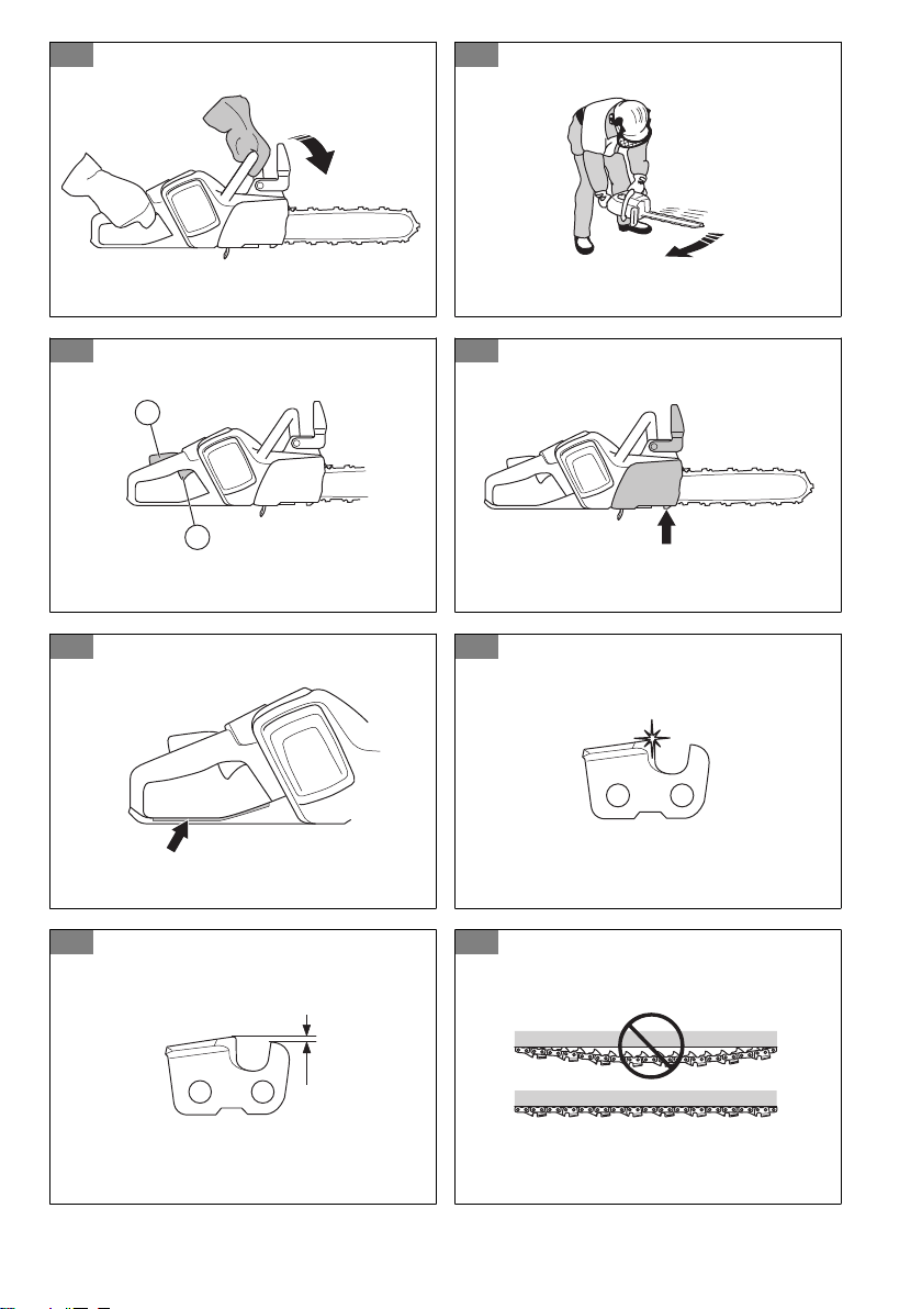
Chain brake and front hand guard
Your product has a chain brake that stops the saw chain
if you get a kickback. The chain brake decreases the
risk of accidents but only you can prevent them.
(Fig. 21)
WARNING:
Do not engage in situations
where there is a risk of kickback. Be careful
when you use your product and make sure
20 1782 - 006 - 01.12.2022

that the kickback zone of the guide bar does
not touch an object.
(Fig. 22)
The chain brake engages (A) manually by your left hand
or automatically by the inertia release mechanism. Push
the front hand guard (B) forward to engage the chain
brake manually. This movement starts a spring-loaded
mechanism that stops the drive sprocket.
(Fig. 23)
How the chain brake is engaged is in relation to the
force of the kickback and position of the product. If
you get an intense kickback while the kickback zone is
farthest away from you, the chain brake engages by the
inertia release. If the kickback is small or the kickback
zone is nearer you, the chain brake engages manually
by your left hand.
(Fig. 24)
Use the chain brake as a parking brake when you
start the product and when you move short distances.
This decreases the risk that you or a person near you
touches the saw chain.
(Fig. 25)
Pull the front hand guard rearward to disengage the
chain brake.
(Fig. 26)
A kickback can be very sudden and intense. Most
kickbacks are small and do not always engage the chain
brake. If a kickback occurs when you use the product,
hold tightly around the handles and do not let go.
(Fig. 27)
The front hand guard also decreases the risk to touch
the saw chain if your hand lets go of the front handle.
(Fig. 28)
In the felling position you cannot engage the chain brake
manually. The chain brake can in this position only be
engaged by the inertia release mechanism.
(Fig. 29)
Power trigger lockout
The power trigger lockout prevents accidental operation
of the power trigger. If you put your hand around
the handle and press the power trigger lockout (A), it
releases the power trigger (B). If you release the handle,
the power trigger and the power trigger lockout move
back to their initial positions.
(Fig. 30)
Chain catcher
The chain catcher catches the saw chain if it breaks or
comes loose. If you have the correct chain tension, the
risk decreases. You also decrease the risk if you do the
correct maintenance on the guide bar and saw chain.
See
Assembly on page 22
and
Maintenance on page
27
for instructions.
(Fig. 31)
Right hand guard
The right hand guard works as a protection for your
hand if the saw chain breaks or comes loose. It also
prevents interference from branches and twigs when
you use the product.
(Fig. 32)
Safety instructions for the cutting
equipment
WARNING: Read the warning
instructions that follow before you use the
product.
• Only use approved guide bar/saw chain
combinations and filing equipment. Refer to
Technical data on page 30
for instructions.
• Use protective gloves when you use or do
maintenance on the saw chain. A saw chain that
does not move can also cause injuries.
• Keep the cutting teeth correctly sharpened. Obey the
instructions and use the recommended file gauge. A
saw chain that is damaged or incorrectly sharpened
increases the risk of accidents.
(Fig. 33)
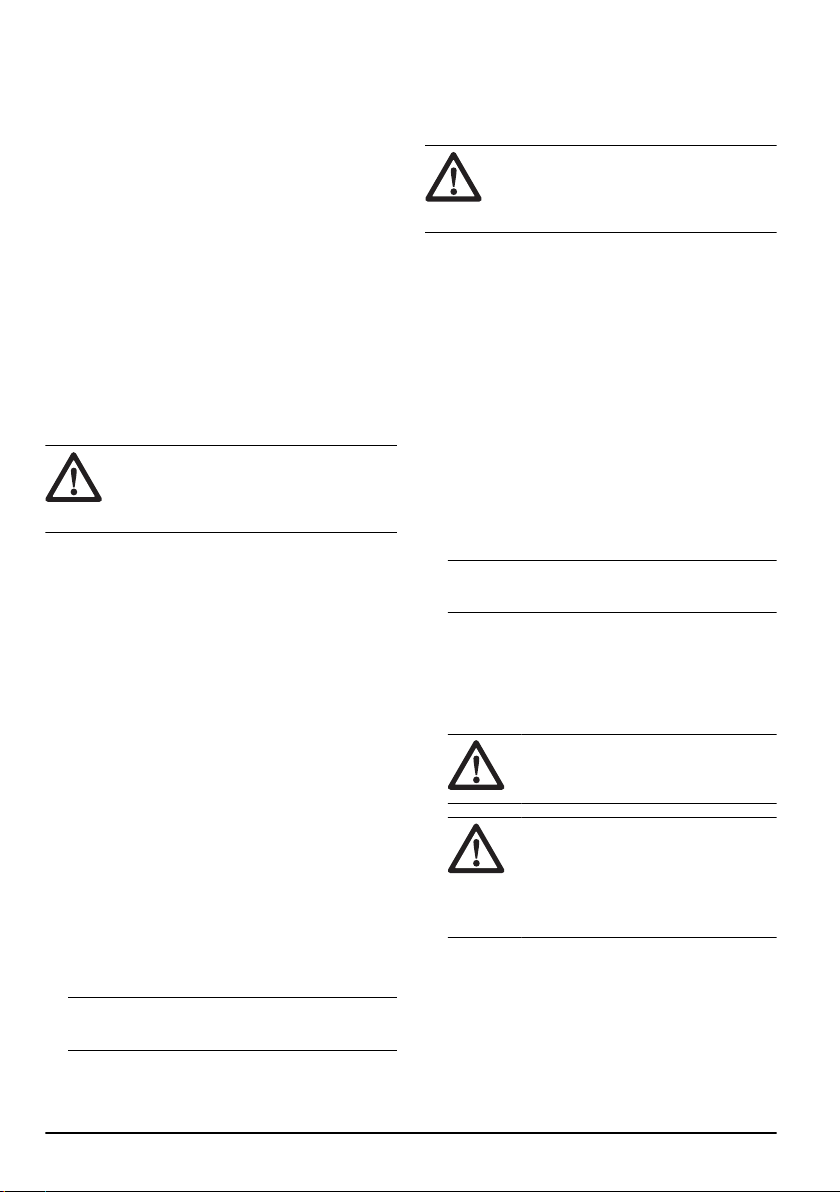
• Keep the correct depth gauge setting. Obey the
instructions and use the recommended depth gauge
setting. Too large depth gauge setting increases the
risk of kickback.
(Fig. 34)
• Make sure that the saw chain has the correct
tension. If the saw chain is not tight against the
guide bar, the saw chain can derail. An incorrect saw
chain tension increases wear on the guide bar, saw
chain and chain drive sprocket. Refer to
To adjust
the tension of the saw chain on page 29
.
(Fig. 35)
• Do maintenance on the cutting equipment regularly
and keep it correctly lubricated. If the saw chain is
not correctly lubricated, the risk of wear on the guide
bar, saw chain and chain drive sprocket increases.
(Fig. 36)
• Protection against electric shock. Saws used in the
open air must be connected to a residual current-
operated circuit-breaker with an operating current no
higher than 30 mA.
• Safe working practices. Keep the cord away from the
cutting area and to position cord so that it will not be
caught on branches, and the like, during cutting.
1782 - 006 - 01.12.2022
21

Assembly
To assemble the guide bar and saw
chain (420 EL)
WARNING: Always remove the plug
before you assemble or do maintenance on
the product.
1. Disengage the chain brake. (Fig. 37)
2. Loosen the knob and remove the drive sprocket
cover (chain brake) and the transportation ring (A).
(Fig. 38)
3. Put the guide bar on top of the bar bolt. Steer the
guide bar to its most rear position. Lift the saw chain
above the drive sprocket and engage it in the groove
on the guide bar. Start on the top edge of the guide
bar.
4. Make sure that the edges of the cutting links are
turned forward on the top edge of the guide bar. (Fig.
39)
5. Make sure that the edges of the cutting links face
forward on the top edge of the guide bar.
6. Assemble the drive sprocket cover and steer the
chain adjuster pin to the hole in the guide bar.
7. Make sure that the drive links of the saw chain fit
correctly on the drive sprocket.
8. Make sure that the saw chain is correctly engaged in
the groove in the guide bar.
9. Tighten the saw chain. See
To adjust the tension of
the saw chain (420 EL) on page 29
for instructions.
Operation
Introduction
WARNING: Read and understand the
safety chapter before you use the product.
To do a function check before you use
the product
1. Do a check of the chain brake (A) to make sure that
it operates correctly and that it is not damaged.
2. Do a check of the rear right hand guard (B) to make
sure that it is not damaged.
3. Do a check of the power trigger and the power
trigger lockout (C) to make sure that they operate
correctly and that they are not damaged.
4. Do a check of the keypad (D) to make sure that it
operates correctly.
5. Make sure that there is no oil on the handles (E).
6. Do a check to make sure that all parts are correctly
attached and not damaged or missing.
7. Do a check of the chain catcher (F) to make sure
that it is attached correctly.
8. Do a check of the chain tension (G).
9. Make sure that the saw chain stops when you
release the power trigger. (Fig. 40)
To use the correct chain oil
WARNING: Do not use waste oil,
which can cause injury to you and the
environment. Waste oil also causes damage
to the oil pump, the guide bar and the saw
chain.
WARNING: The saw chain can break
if the lubrication of the cutting equipment is
not sufficient. Risk of serious injury or death
to the operator.
WARNING: Use the correct chain oil
for this function to operate correctly. Speak
to your servicing dealer when you select
your chain oil.
• Use Husqvarna chain oil for maximum saw chain life
and to prevent negative effects on the environment.
If Husqvarna chain oil is not available, we
recommend you to use a standard chain oil.
• Use a chain oil with good adherence to the saw
chain.
• Use a chain oil with correct viscosity range that
agrees with the air temperature.
CAUTION: In temperatures below
0°C/32°F some chain oils become too
thick, which can cause damage to the oil
pump components.
• Use the recommended cutting equipment. Refer to
Accessories on page 32
.
• Remove the cap to the chain oil tank.
• Fill the chain oil tank with chain oil.
• Attach the cap carefully.
(Fig. 41)
22
1782 - 006 - 01.12.2022

Note: To see where the chain oil tank is on you
product, refer to
Product overview on page 17
.
Kickback information
WARNING: A kickback can cause
serious injury or death to the operator or
others. To decrease the risk you must know
the causes of kickback and how to prevent
them.
A kickback occurs when the kickback zone of the guide
bar touches an object. A kickback can occur suddenly
and with large force, which throws the product in the
direction of the operator.
(Fig. 22)
Kickback always occurs in the cutting plane of the guide
bar. Usually, the product is thrown against the operator
but can also move in a different direction. It is how you
use the product when the kickback occurs that causes
the direction of the movement.
(Fig. 42)
Kickback only occurs if the kickback zone of the guide
bar touches an object. Do not let the kickback zone
touch an object.
(Fig. 22)
A smaller bar tip radius decreases the force of the
kickback.
Use a low kickback saw chain to decrease the effects of
kickback. Do not let the kickback zone touch an object.
WARNING:
No saw chain fully
prevents kickback. Always obey the
instructions.
Common questions about kickback
• Will the hand always engage the chain brake during
a kickback?
No. It is necessary to use some force to push the
front hand guard forward. If you do not use the force
necessary, the chain brake will not be engaged. You
must also hold the handles of the product stable with
two hands during work. If a kickback occurs, it is
possible that the chain brake does not stop the saw
chain before it touches you. There are also some
positions in which your hand can not touch the front
hand guard to engage the chain brake.
• Will the inertia release mechanism always engage
the chain brake during kickback?
No. First, the chain brake must operate correctly.
Refer to
Maintenance and checks of the safety
devices on the product on page 27
for instructions
about how to do a check of the chain brake. We
recommend you to do this each time before you
use the product. Second, the force of the kickback
must be large to engage the chain brake. If the chain
brake is too sensitive, it can engage during rough
operation.
• Will the chain brake always protect me from injury
during a kickback?
No. The chain brake must operate correctly to give
protection. The chain brake must also be engaged
during a kickback to stop the saw chain. If you are
near the guide bar, it is possible that the chain brake
does not have time to stop the saw chain before it
hits you.
WARNING: Only you and the correct
working technique can prevent kickbacks.
To start the product
1. Do a check of the power trigger and power trigger
lockout. See
Power trigger lockout on page 21
.
2. Push the front hand guard forward to engage the
chain brake. (Fig. 43)
3. Hold the front handle with your left hand.
4. Hold the rear handle with your right hand.
5. Press and hold the power trigger lockout and press
the power trigger. (Fig. 44)
To stop the product
1. Release the power trigger.
2. Push the front hand guard to engage the chin brake.
Pull stroke and push stroke
You can cut through wood with the product in 2 different
positions.
• To cut on the pull stroke is when you cut with the
bottom of the guide bar. The saw chain pulls through
the tree when you cut. In this position you have
better control of the product and the position of the
kickback zone.
(Fig. 45)
• To cut on the push stroke is when you cut with the
top of the guide bar. The saw chain pushes the
product in the direction of the operator.
(Fig. 46)
WARNING:
If the saw chain is
caught in the trunk, the product can be
pushed at you. Hold the product tightly
and make sure that the kickback zone
of the guide bar does not touch the tree
and causes a kickback.
(Fig. 47)
1782 - 006 - 01.12.2022
23

To use the cutting technique
WARNING: Use full power when you
cut and decrease the speed to idle speed
after each cut.
CAUTION: Do not let the motor operate
for too long without load. This can cause
damage to the motor.
1. Put the trunk on a saw horse or runners. (Fig. 48)
WARNING: Do not cut trunks in a
pile. That increases the risk of kickback
and can cause serious injury or death.
2. Remove the cut pieces from the work area.
WARNING: Cut pieces in the work
area increase the risk of kickback and
that you cannot keep your balance.
To use the spiked bumper
1. Push the spiked bumper into the trunk of the tree.
2. Apply full throttle and rotate the product. Keep the
spiked bumper against the trunk. This procedure
makes it easier to apply the force necessary to cut
through the trunk. (Fig. 49)
To cut a trunk on the ground
1. Cut through the trunk on the pull stroke. Keep full
power but be prepared for sudden accidents. (Fig.
50)
WARNING:
Make sure that the saw
chain does not touch the ground when
you complete the kerf.
2. Cut approximately ⅔ through the trunk and then
stop. Turn the trunk and cut from the opposite side.
(Fig. 51)
To cut a trunk that has support on one end
WARNING:
Make sure that the trunk
does not break during cutting. Obey the
instructions below.
(Fig. 52)
1. Cut on the push stroke approximately ⅓ through the
trunk.
2. Cut through the trunk on the pull stroke until the two
kerfs touch. (Fig. 53)
To cut a trunk that has support on two ends
WARNING: Make sure that the saw
chain does not get caught in the trunk during
cutting. Obey the instructions below.
(Fig. 54)
1. Cut on the pull stroke approximately ⅓ through the
trunk.
2. Cut through the remaining part of the trunk on the
push stroke to complete the cut. (Fig. 55)
WARNING: Stop the motor if the saw
chain gets caught in the trunk. Use a lever
to open up the kerf and remove the product.
Do not try to pull the product out by hand.
This can result in injury when the product
suddenly breaks free.
To use the limbing technique
Note: For thick branches, use the cutting technique.
Refer to
To use the cutting technique on page 24
.
WARNING: There is a high accident
risk when you use the limbing technique.
Refer to
Kickback information on page 23
for
instructions how to prevent kickback.
WARNING: Cut limbs one by one. Be
careful when you remove small limbs and do
not cut bushes or many small limbs at the
same time. Small limbs can get caught in the
saw chain and prevent safe operation of the
product.
Note: If it is necessary, cut the limbs piece by piece.
Cut the smaller branches (A) and (B) before you cut the
limb near the trunk (C).
(Fig. 56)
1. Remove the limbs on the right side of the trunk.
a) Keep the guide bar on the right side of the trunk
and keep the body of the product against the
trunk.
b) Select the applicable cutting technique for the
tension in the branch. (Fig. 57)
WARNING:
If you are not sure
about how to cut the branch, speak
to a professional chainsaw operator
before you continue.
2. Remove the limbs on the top of the trunk.
24
1782 - 006 - 01.12.2022

a) Keep the product on the trunk and let the guide
bar move along the trunk.
b) Cut on the push stroke. (Fig. 58)
3. Remove the limbs on the left side of the trunk.
a) Select the applicable cutting technique for the
tension in the branch. (Fig. 59)
WARNING: If you are not sure
about how to cut the branch, speak
to a professional chainsaw operator
before you continue.
Refer to
To cut trees and branches that are in tension
on page 26
for instructions on how to cut branches that
are in tension.
To use the tree felling technique
WARNING: You must have experience
to fell a tree. If possible, engage in
a training course in chainsaw operation.
Speak to an operator with experience for
more knowledge.
To keep a safe distance
1. Make sure that persons around you keep a safe
distance at a minimum of 2 1/2 tree lengths. (Fig.
60)
2. Make sure that no person is in the risk zone before
or during felling. (Fig. 61)
To calculate the felling direction
1. Examine in which direction it is necessary for the
tree to fall. The goal is to fell it in a position where
you can limb and cut the trunk easily. It is also
important that you are stable on your feet and can
move about safely.
WARNING:
If it is dangerous or not
possible to fell the tree in its natural
direction, fell the tree in a different
direction.
2. Examine the natural fall direction of the tree. For
example the tilt and bend of the tree, wind direction,
the location of the branches and weight of snow.
3. Examine if there are obstacles, for example other
trees, power lines, roads and/or buildings around.
4. Look for signs of damage and rot in the stem.
WARNING:
Rot in the stem can
mean a risk that the tree falls before you
complete the cutting.
5. Make sure the tree has no damaged or dead
branches that can break off and hit you during
felling.
6. Do not let the tree fall onto a different standing tree.
It is dangerous to remove a caught tree and there is
a high accident risk. Refer to
To free a trapped tree
on page 26
. (Fig. 62)
WARNING: During critical felling
operations, lift your hearing protection
immediately when the sawing is
complete. It is important that you hear
sounds and warning signals.
To clear the trunk and prepare your path of
retreat
Cut off all branches from your shoulder height and
down.
1. Cut on the pull stroke from the top down. Make sure
that the tree is between you and the product. (Fig.
63)
2. Remove undergrowth from the work area around the
tree. Remove all cut off material from the work area.
3. Do a check of the area for obstacles such as stones,
branches and holes. You must have a clear path
of retreat when the tree starts to fall. Your path of
retreat must be approximately 135 degrees away
from the felling direction.
1. The danger zone
2. The path of retreat
3. The felling direction
(Fig. 64)
To fell a tree
Husqvarna recommends you to make the directional
cuts and then use the safe corner method when you
fell a tree. The safe corner method helps you to make a
correct felling hinge and control the felling direction.
WARNING:
Do not fell trees with a
diameter that is more than two times larger
than the guide bar length. For this, you must
have special training.
The felling hinge
The most important procedure during tree felling is to
make the correct felling hinge. With a correct felling
hinge, you control the felling direction and make sure
that the felling procedure is safe.
The thickness of the felling hinge must be equal and a
minimum of 10% of the tree diameter.
WARNING:
If the felling hinge is
incorrect or too thin, you have no control of
the felling direction.
(Fig. 65)
1782 - 006 - 01.12.2022
25
To make the directional cuts
1. Make the directional cuts. Run the directional cuts
1/4 of the diameter of the tree. Make a 45° angle
between the top cut and bottom cut.
a) Make the top cut first. Align the felling direction
mark (A) of the product with the felling direction
of the tree (B). Stay behind the product and keep
the tree on your right side. Cut with a pull stroke.
b) Make the bottom cut. Make sure that the end of
the bottom cut is at the same point as the end of
the top cut. (Fig. 66)
2. Make sure that the directional cut line is perfectly
horizontal and at right angles (90°) to the felling
direction. The directional cut line goes through the
point where the two directional cuts touch. (Fig. 67)
To use the safe corner method
The felling cut must be made slightly above the
directional cut.
(Fig. 68)
WARNING: Be careful when you cut
with the guide bar tip. Start to cut with the
lower section of the guide bar tip as you
make a bore cut into the trunk.
(Fig. 69)
1. If the usable cutting length is longer than the tree
diameter, do these steps (a-d).
a) Make a bore cut straight into the trunk to
complete the felling hinge width. (Fig. 70)
b) Cut on the pull stroke until ⅓ of the trunk is left.
c) Pull the guide bar 5-10 cm/2-4 in rearward.
d) Cut through the remaining of the trunk to
complete a safe corner that is 5-10 cm/2-4 in
wide. (Fig. 71)
2. If the usable cutting length is shorter than the tree
diameter, do these steps (a-d).
a) Make a bore cut straight into the trunk. The bore
cut must extend 3/5 of the tree diameter.
b) Cut on the pull stroke through the remaining
trunk. (Fig. 72)
c) Cut straight into the trunk from the other side of
the tree to complete the felling hinge.
d) Cut on the push stroke, until ⅓ of the trunk is left,
to complete the safe corner. (Fig. 73)
3. Put a wedge in the kerf straight from behind. (Fig.
74)
4. Cut off the corner to make the tree fall.
Note:
If the tree does not fall, hit the wedge until it
does.
5. When the tree starts to fall, use the path of retreat
to move away from the tree. Move a minimum of 5
m/15 ft away from the tree.
To free a trapped tree
WARNING: It is very dangerous to
remove a trapped tree and there is a high
accident risk. Keep out of the risk zone and
do not try to fell a trapped tree.
(Fig. 75)
The safest procedure is to use one of the following
winches:
• Tractor-mounted
(Fig. 76)
• Portable
(Fig. 77)
To cut trees and branches that are in tension
1. Figure out which side of the tree or branch that is in
tension.
2. Figure out where the point of maximum tension is.
(Fig. 78)
3. Examine which is the safest procedure to release the
tension.
Note: In some situations the only safe procedure
is to use a winch and not your product.
4. Keep a position where the tree or branch can not hit
you when the tension is released. (Fig. 79)
5. Make one or more cuts of sufficient depth necessary
to decrease the tension. Cut at or near the point of
maximum tension. Make the tree or branch break at
the point of maximum tension. (Fig. 80)
WARNING:
Do not cut straight
through a tree or branch that is in
tension.
WARNING: Be very careful when
you cut a tree that is in tension. There is
a risk that the tree moves quickly before
or after you cut it. Serious injury can
occur if you are in an incorrect position
or if you cut incorrectly.
6. If you must cut across tree/branch, make 2 to 3 cuts,
1 in. apart and with a depth of 2 in. (Fig. 81)
7. Continue to cut more into the tree until the tree/
branch bends and the tension is released. (Fig. 82)
8. Cut the tree/branch from the opposite side of the
bend, after the tension is released.
26
1782 - 006 - 01.12.2022

Maintenance
Introduction
WARNING: Read and understand the
safety chapter before you do maintenance
on the product.
Maintenance schedule
WARNING: Remove the power plug
from the power outlet before you do
maintenance.
The following is a list of the maintenance steps that you
must do on the product. See
Safety on page 18
for more
information.
Maintenance Before
use
Weekly Monthly
Clean the external parts of the product. X
Make sure that the power trigger and the power trigger lockout function correctly
from a safety point of view.
X
Clean the chain brake and make sure that it operates safely. Make sure that the
chain catcher is not damaged. Replace it if necessary.
X
Turn the guide bar for more equal wear. Make sure that the lubrication hole in
the guide bar is not clogged. Clean the bar groove.
X
Make sure that the cutter and cutter guard have no cracks and that they are not
damaged. Replace the cutter or cutter guard if they have cracks or if they have
been exposed to impact.
X
Make sure that the guide bar and saw chain have sufficient oil. X
Do a check of the saw chain. Look for cracks and make sure that the saw chain
is not rigid or unusually worn. Replace if necessary.
X
Sharpen the saw chain. Do a check of its tension and condition. Do a check for
wear on the drive sprocket and replace is necessary.
X
Clean the air inlet on the product. X
Make sure that the screws and nuts are tight. X
Use a file to remove burrs from the edges of the guide bar. X
Empty and clean the oil tank. X
Blow through the product gently with compressed air. X
Maintenance and checks of the safety
devices on the product
To do a check of the front hand guard
Regularly do a check of the front hand guard and the
inertia brake release.
1. Make sure that the front hand guard is not damaged
and that there are no defects, such as cracks. (Fig.
83)
2. Make sure that the front hand guard moves freely
and that it is attached safely to the product. (Fig. 84)
3. Put the product, with the motor off, on a stump or
other stable surface.
4. Hold the rear handle and let go of the front handle.
Let the product fall against the stump. (Fig. 85)
5. Make sure that the chain brake engages as the
guide bar hits the stump.
1782 - 006 - 01.12.2022 27

To do a check of the brake trigger
1. Put the product on stable ground and start it. See
To
start the product on page 23
.
WARNING: Make sure that the saw
chain does not touch the ground or other
objects.
2. Wrap your fingers and thumbs around the handles
and hold the product tight. (Fig. 86)
3. Apply full power and tilt your left wrist against the
front hand guard to engage the chain brake. The
saw chain must stop immediately. (Fig. 87)
WARNING: Do not let go of the front
handle!
To do a check of the power trigger lockout
1. Make sure that the power trigger and power trigger
lockout move freely and that the return spring works
correctly. (Fig. 88)
2. Press down the power trigger lockout and make
sure that it goes back to its initial position when you
release it. (Fig. 89)
3. Make sure that the power trigger is locked at the idle
position when the power trigger lockout is released.
(Fig. 90)
4. Start the product and apply full power.
5. Release the power trigger and make sure that the
saw chain stops and stays stationary. If the saw
chain rotates when the power trigger is in the idle
position, turn to your servicing dealer.
To do a check of the chain catcher
1. Make sure that there is no damage on the chain
catcher.
2. Make sure that the chain catcher is stable and
attached to the body of the product. (Fig. 91)
To clean the cooling system
The product has a cooling system that keeps the
temperature of the product as low as possible.
The cooling system includes an air intake on the left side
of the product and a fan on the motor.
1. Clean the cooling system with a brush weekly or
more frequently if necessary.
2. Make sure that the cooling system is not dirty or
blocked.
CAUTION:
A dirty or blocked
cooling system can cause the product to
become too hot. This causes damage to
the piston and cylinder.
To sharpen the saw chain
Information about the guide bar and saw chain
WARNING: Use protective gloves
when you use or do maintenance on the
saw chain. A saw chain that does not move
can also cause injuries.
Replace a worn or damaged guide bar or saw chain with
the guide bar and saw chain combination recommended
by Husqvarna. This is necessary to keep the safety
functions of the product. Refer to
Accessories on
page 32
, for a list of replacement bar and chain
combinations that we recommend.
• Guide bar length, in/cm. Information about the guide
bar length can usually be found on the rear end of
the guide bar.
(Fig. 92)
• Number of teeth on bar tip sprocket (T).
(Fig. 93)
• Chain pitch, in. The distance between the drive links
of the saw chain must align with the distance of the
teeth on the bar tip sprocket and drive sprocket.
(Fig. 94)
• Number of drive links. The number of drive links is
decided by the type of guide bar.
(Fig. 95)
• Bar groove width, in/mm. The groove width in guide
bar must be the same as the chain drive links width.
(Fig. 96)
• Chain oil hole and hole for chain tensioner. The
guide bar must align with product.
(Fig. 97)
• Drive link width, mm/in.
(Fig. 98)
General information about how to sharpen the
cutters
Do not use a blunt saw chain. If the saw chain is blunt,
you must apply more pressure to push the guide bar
through the wood. If the saw chain is very blunt, there
will be no wood chips but sawdust.
A sharp saw chain eats through the wood and the wood
chips becomes long and thick.
The cutting tooth (A) and the depth gauge (B) together
makes the cutting part of the saw chain, the cutter. The
difference in height between the two gives the cutting
depth (depth gauge setting).
(Fig. 99)
When you sharpen the cutter, think about the following:
28
1782 - 006 - 01.12.2022

• Filing angle.
(Fig. 100)
• Cutting angle.
(Fig. 101)
• File position.
(Fig. 102)
• Round file diameter.
(Fig. 103)
It is not easy to sharpen a saw chain correctly without
the correct equipment. Use Husqvarna file gauge. This
will help you to keep maximum cutting performance and
the kickback risk at a minimum.
WARNING: The force of the kickback
increases a lot if you do not follow the
sharpening instructions.
Note: Refer to
To sharpen the cutters on page 29
for
information about sharpening of the saw chain.
To sharpen the cutters
1. Use a round file and a file gauge to sharpen the
cutting teeth. (Fig. 104)
Note: Refer to
Accessories on page 32
for information about which file and gauge that
Husqvarna recommends for your saw chain.
2. Apply the file gauge correctly on to the cutter. Refer
to the instruction supplied with the file gauge.
3. Move the file from the inner side of the cutting teeth
and out. Decrease the pressure on the pull stroke.
(Fig. 105)
4. Remove material from one side of all the cutting
teeth.
5. Turn the product around and remove material on the
other side.
6. Make sure that all cutting teeth are the same length.
General information about how to adjust the
depth gauge setting
The depth gauge setting (C) decreases when you
sharpen the cutting tooth (A). To keep maximum
cutting performance you must remove filing material
from the depth gauge (B) to receive the recommended
depth gauge setting. See
Accessories on page 32
for instructions about how to receive the correct depth
gauge setting for your saw chain.
(Fig. 106)
WARNING:
The risk of kickback
increases if the depth gauge setting is too
large!
To adjust the depth gauge setting
Before you adjust the depth gauge setting or sharpen
the cutters, refer to
To sharpen the cutters on page
29
, for instructions. We recommend you to adjust the
depth gauge setting after each third operation that you
sharpen the cutting teeth.
We recommend that you use our depth gauge tool to
receive the correct depth gauge setting and bevel for the
depth gauge.
(Fig. 107)
1. Use a flat file and a depth gauge tool to adjust
the depth gauge setting. Only use Husqvarna depth
gauge tool to get the correct depth gauge setting and
bevel for the depth gauge.
2. Put the depth gauge tool on the saw chain.
Note: See the package of the depth gauge tool for
more information about how to use the tool.
3. Use the flat file to remove the part of the depth
gauge that extends through the depth gauge tool.
(Fig. 108)
To adjust the tension of the saw chain
WARNING: A saw chain with an
incorrect tension can come loose from the
guide bar and cause serious injury or death.
A saw chain becomes longer when you use it. Adjust
the saw chain regularly. Do a check of the saw chain
tension each time you fill with chain oil.
Note:
A new saw chain has a run-in period during
which you must do a check of the tension more
frequently.
To adjust the tension of the saw chain (420
EL)
1. Fold the knob out until it opens. (Fig. 109)
2. Turn the knob counterclockwise to loosen the drive
sprocket cover. (Fig. 110)
3. Turn the chain tensioner wheel to adjust the tension
on the saw chain. The saw chain must be tight
against the guide bar. (Fig. 111)
Note:
Turn the wheel down (+) for more tension
and up (-) for less tension.
4. Make sure that you can pull the saw chain around
freely by hand and that it does not hang from the
guide bar. (Fig. 112)
5. Turn the knob clockwise to tighten the bar knob.
(Fig. 113)
6. Fold down the knob to lock the tension. (Fig. 114)
1782 - 006 - 01.12.2022
29

To do a check of the saw chain
lubrication
1. Start the product and let it run at 3/4 power. Hold
the bar approximately 20 cm (8 inches) above a light
coloured surface.
2. If the saw chain lubrication is correct, you will see a
clear line of oil on the surface after 1 minute. (Fig.
115)
3. If the saw chain lubrication is not correct, do the
following checks.
a) Do a check of the oil channel in the guide bar
to make sure that it is not blocked. Clean if
necessary. (Fig. 116)
b) Do a check of the groove in the edge of the
guide bar to make sure that it is clean. Clean if
necessary. (Fig. 117)
c) Make sure that the bar tip sprocket turns freely
and that the lubricating hole in the guide bar tip
sprocket is not blocked. Clean and lubricate if
necessary. (Fig. 118)
4. If the saw chain lubrication does not work after
following the steps above, speak to your servicing
dealer.
To do a check of the chain drive
sprocket
• Examine the chain drive sprocket for wear. Replace
the chain drive sprocket if it is necessary.
• Replace the chain drive sprocket (A) each time that
you replace the saw chain. (Fig. 119)
To examine the cutting equipment
1. Make sure that there are no cracks in rivets and
links and that no rivets are loose. Replace if it is
necessary. (Fig. 120)
2. Make sure that the saw chain is easy to bend.
Replace the saw chain if it is rigid.
3. Compare the saw chain with a new saw chain to
examine if the rivets and links are worn.
4. Replace the saw chain when the longest part of the
cutting tooth is less than 4 mm/0.16 in. Also replace
the saw chain if there are cracks on the cutters. (Fig.
121)
To do a check of the guide bar
1. Make sure that the oil channel is not blocked. Clean
if it is necessary. (Fig. 116)
2. Examine if there are burrs on the edges of the guide
bar. Remove the burrs using a file. (Fig. 122)
3. Clean the groove in the guide bar. (Fig. 117)
4. Examine the groove in the guide bar for wear.
Replace the guide bar if it is necessary. (Fig. 123)
5. Examine if the guide bar tip is rough or very worn.
(Fig. 124)
6. Make sure that the bar tip sprocket turns freely and
that the lubricating hole in the bar tip sprocket is not
blocked. Clean and lubricate if it is necessary. (Fig.
118)
7. Turn the guide bar daily to extend its life cycle. (Fig.
125)
Transportation, storage and disposal
Transportation and storage
• Obey the special requirement on package and labels
for commercial transportation, including by third
parties and forwarding agents.
• Speak to a person with special training in dangerous
material before you send the product. Obey all
applicable national regulations.
• Clean the product and do a full servicing before you
put the product in storage for a long time.
• Use the transportation guard on the product to
prevent injuries or damage on the product during
transportation and storage.
• Attach the product safely during transportation.
• Keep the product in a cool and dry environment and
away from children when it is not in use. Do not put
the product in storage outdoors.
Technical data
Technical data
420 EL
Motor
Type Series AC Motor
Power, W 2000
30 1782 - 006 - 01.12.2022

420 EL
Voltage range, V 230-240
Lubrication system
Type of oil pump Automatic
Oil tank capacity, liter/cm
2
0.20/200
Weight
Chainsaw without guide bar, saw chain and empty chain oil tank (EPTA-Pro-
cedure 01/2014), kg
4.7-5.6
Noise emissions
1
Sound power level, measured dB(A) 100
Sound power level, guaranteed L
WA
dB(A) 103
Sound levels
2
Equivalent sound pressure level at the operator's ear, dB(A) / Uncertaity (K)
m/s
2
89/3.0
Vibration levels
3
Front handle m/s
2
/ Uncertaity (K) m/s
2
4.8/1.5
Rear handle m/s
2
/ Uncertaity (K) m/s
2
6.7/1.5
Equivalent vibration levels
4
Front handle m/s
2
2.2
Rear handle m/s
2
2.4
Saw chain/guide bar
Recommended bar lengths, inch/cm 16/40
Usable cutting length, inch/cm 14/35.5
Type of drive sprocket/number of teeth Spur/6
Maximum chain speed, m/s 14.5
1
Noise emissions in the environment measured as sound power (L
WA
) in conformity with EC directive
2000/14/EC.
2
Reported data for sound pressure level for the machine has a typical statistical dispersion (standard deviation)
of 2 dB (A).
3
Vibration level, according to EN 62841-4-1. Reported data for vibration level has a typical statistical dispersion
(standard deviation) of 1.5 m/s
2
. Declared vibration data from measurements when the machine is fitted with a
bar length and recommended chain type.
4
Equivalent vibration level is measured and calculated as for combustion engine powered chainsaws. These
figures are quoted to be able to compare vibration data regardless of type of engine according to ISO
22867:2011.
1782 - 006 - 01.12.2022 31

Accessories
Guide bar and saw chain combinations
The cutting attachments below are approved for the
model 420 EL
Guide bar Saw chain
Length, cm (in) Pitch, mm (in) Gauge, mm (in) Max. nose radius Type Drive link count
40 (16) 9,52 (3/8) 1,3 (0,050) 7T Husqvarna H37 56
Filing equipment and filing angles
Using Husqvarna file gauge will give you the correct
filing angles. We recommend you to always use a
Husqvarna file gauge to restore the sharpness of the
saw chain. The part numbers are given in the table
below.
If you do not know which saw chain you have on your
product, turn to your servicing dealer.
37
5/32 in / 4.0
mm
80° 30° 0°
0.025 in/0.65
mm
5796536-01
32 1782 - 006 - 01.12.2022

Declaration of Conformity
EU Declaration of Conformity
We, Husqvarna AB, SE-561 82 Huskvarna, Sweden, tel:
+46-36-146500, declare on our sole responsibility that
the product:
Description Chainsaw for forest service
Brand Husqvarna
Type / Model 420 EL
Identification Serial numbers dating from 2022 and onwards
complies fully with the following EU directives and
regulations:
Regulation Description
2006/42/EC "relating to machinery"
2014/30/EU "relating to electromagnetic compatibility"
2000/14/EC ”relating to the noise emissions in the environment”
2011/65/EU “on the restriction of the use of certain hazardous substances in electrical and electronic
equipment”
and that the following standards and/or technical
specifications are applied: EN 62841-1:2015, EN
62841-4-1:2020, EN IEC 55014-1:2021, EN IEC
55014-2:2021, EN IEC 61000-3-2:2019+A1:2021, EN
61000-3-3:2013+A1:2019.
Notified body: NB0158, DEKRA Testing & Certification
GmbH, Handwerkstraße 15, D-70565, Stuttgart,
Germany has carried out EC type examination in
accordance with the machinery directive's (2006/42/EC)
article 12, clause 3b, annex IX on behalf of Husqvarna
AB.
Certificate number: 4815039.22004
For information relating to noise emissions, refer to
Technical data on page 30
.
Huskvarna, 2022-12-01
Stefan Holmberg, R&D Director, Technology
Management, Husqvarna AB.
Responsible for technical documentation.
1782 - 006 - 01.12.2022 33

UK Declaration of Conformity
We, Husqvarna AB, SE-561 82 Huskvarna, Sweden, tel:
+46-36-146500, declare on our sole responsibility that
the product:
Description Chainsaw for forest service
Brand Husqvarna
Type / Model 420 EL
Identification Serial numbers dating from 2022 and onwards
complies fully with the following UK regulations:
Regulations Description
S.I. 2008/1597 "The Supply of Machinery (Safety)"
S.I. 2016/1091 "The Electromagnetic Compatibility"
S.I. 2001/1701 ”The Noise Emission in the Environment by Equipment for use Outdoors”
S.I. 2012/3032 “The Restriction of the Use of Certain Hazardous Substances in Electrical and Electronic
Equipment”
and that the following designated standards and/or
technical specifications are applied: EN 62841-1:2015,
EN 62841-4-1:2020, EN IEC 55014-1:2021, EN IEC
55014-2:2021, EN IEC 61000-3-2:2019+A1:2021, EN
61000-3-3:2013+A1:2019.
Notified body: NB0158, DEKRA Testing & Certification
GmbH, Handwerkstraße 15, D-70565, Stuttgart,
Germany has carried out type examination
in accordance with the machinery regulations
(S.I.2008/1597) clause 11, (2) (b), annex IX on behalf
of Husqvarna AB.
Certificate number: 4815039.22004.
For information relating to noise emissions, refer to
Technical data on page 30
.
Huskvarna, 2022-12-01
Stefan Holmberg, R&D Director, Technology
Management, Husqvarna AB.
Responsible for technical documentation.
UK Importer:
Husqvarna UK Ltd
Preston Road, Co. Durham
DL5 6UP
34 1782 - 006 - 01.12.2022

1782 - 006 - 01.12.2022 35

www.husqvarna.com
Original instructions
1142963-26-885539E228
2022-12-07