
How to obtain a PDF of the owner’s manual
PDF les of the owner’s manual and supplementary material for this product can be obtained from the Roland website.
• SPD-SX Owner’s Manual (this document)
• Eect Guide (Explanation of the eect parameters)
Eect Guide is not included with the product; you may download them as necessary.
Visit the following URL, choose “owner’s manuals,” and search for the model name “SPD-SX.”
http://www.roland.com/support/en/
Owner’s Manual
Before using this unit, carefully read the sections entitled: “USING THE UNIT SAFELY” (p. 74), and “IMPORTANT NOTES” (p. 75). These
sections provide important information concerning the proper operation of the unit. Additionally, in order to feel assured that you
have gained a good grasp of every feature provided by your new unit, Owner’s Manual should be read in its entirety. The manual
should be saved and kept on hand as a convenient reference.
Copyright © 2011 ROLAND CORPORATION
All rights reserved. No part of this publication may be reproduced in any form without the written permission of ROLAND
CORPORATION.
Roland is a registered trademarks or trademarks of Roland Corporation in the United States and/or other countries.
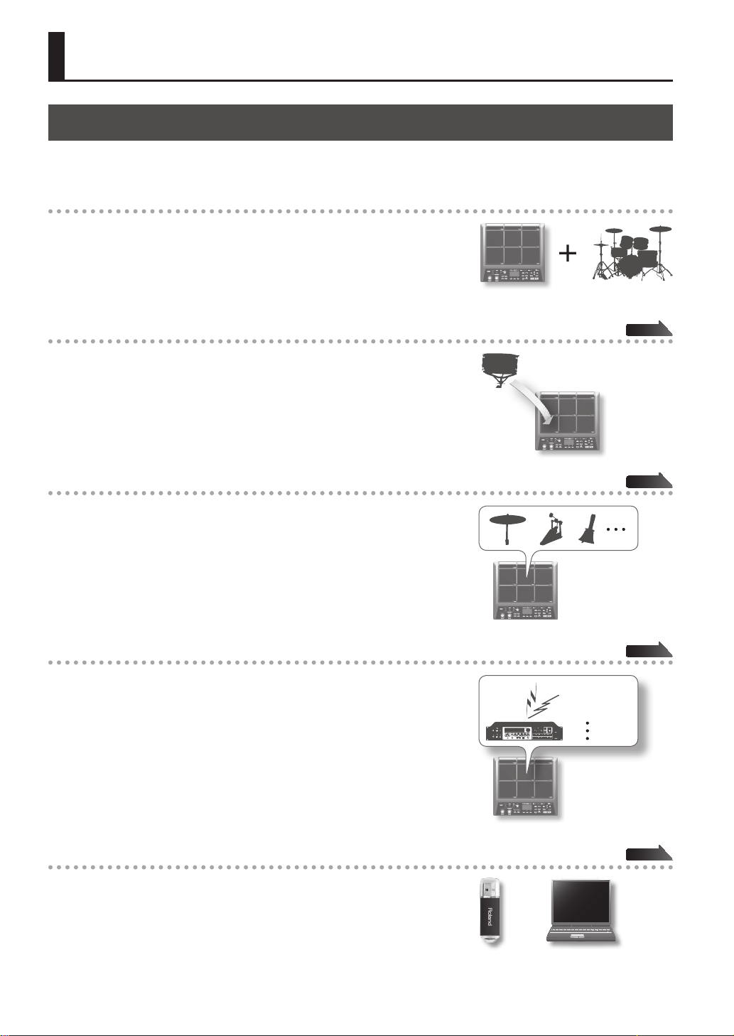
Things You Can Do with the SPD-SX
The SPD-SX is a powerful sampling pad that lets you easily sample original sounds and phrases so you can play them
immediately.
4
Use with a drum set to expand your musical power!
The SPD-SX can be used as a stand-alone instrument for live performances or
in the studio to play backing phrases or sound eects, or in combination with
your acoustic or electronic drum set to expand your musical potentials.
Simple connections, easy sampling!
Sampling your favorite sounds is easy; just connect a microphone or audio
source.
You can also re-sample onboard sounds by performing on the SPD-SX.
Vast performance possibilities with diverse sounds!
The SPD-SX comes loaded with a rich variety of sounds including drums,
percussion and sound eects that can be used for all styles of music.
Ultra-powerful built-in eects!
The SPD-SX contains powerful eects processors that will help go further to
personalize your sounds and music.
Easily import sounds from your computer!
Audio les from your computer or USB ash drive can be imported easily.
SPD-SX data can also be saved to your computer or USB ash drive.
p. 28
p. 20
p. 23
DISTORTION
REVERB
CHORUS
p. 39
Introducing the SPD-SX
Introducing the SPD-SX
Introducing the SPD-SX
5
Overview of the SPD-SX
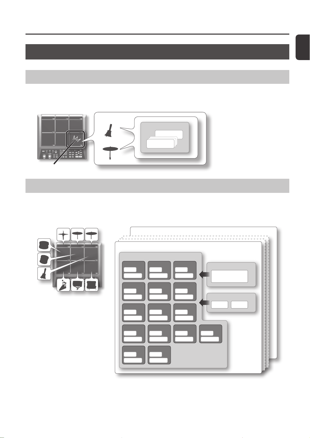
What’s a Wave?
The sound you hear when you play a pad is called a “wave.”
Each sound that you sample or import from a USB ash drive or computer is stored as a wave.
You can simultaneously play two waves (WAVE and SUB WAVE) from a single pad.
WAVE
SUB WAVE
WAVE*****
WAVE00001
Wave
What’s a Kit?
A “kit” consists of all settings for the nine pads, four external pads, and two footswitches.
You can customize a kit by assigning the desired wave to each pad, selecting the eect to be used in that kit and specifying
how they will be played (p. 42).
The SPD-SX contains 100 kits.
*1: Volume of the kit
*2: Tempo of the kit
*3: Eects applied to the kit
KIT
KIT FX
PAD1
WAVE
SUB WAVE
WAVE
SUB WAVE
WAVE
SUB WAVE
WAVE
SUB WAVE
WAVE
SUB WAVE
WAVE
SUB WAVE
WAVE
SUB WAVE
WAVE
SUB WAVE
WAVE
SUB WAVE
WAVE
SUB WAVE
WAVE
SUB WAVE
WAVE
SUB WAVE
WAVE
SUB WAVE
WAVE
SUB WAVE
PAD2 PAD3
PAD4 PAD5 PAD6
PAD7 PAD8 PAD9
TRIG1 TRIG2 TRIG3
WAVE
SUB WAVE
TRIG4
FS1 FS2
KIT PAD
KIT TEMPO *2
KIT VOLUME *1
FX1 *3 FX2 *3
KIT001
KIT100
Introducing the SPD-SX
6
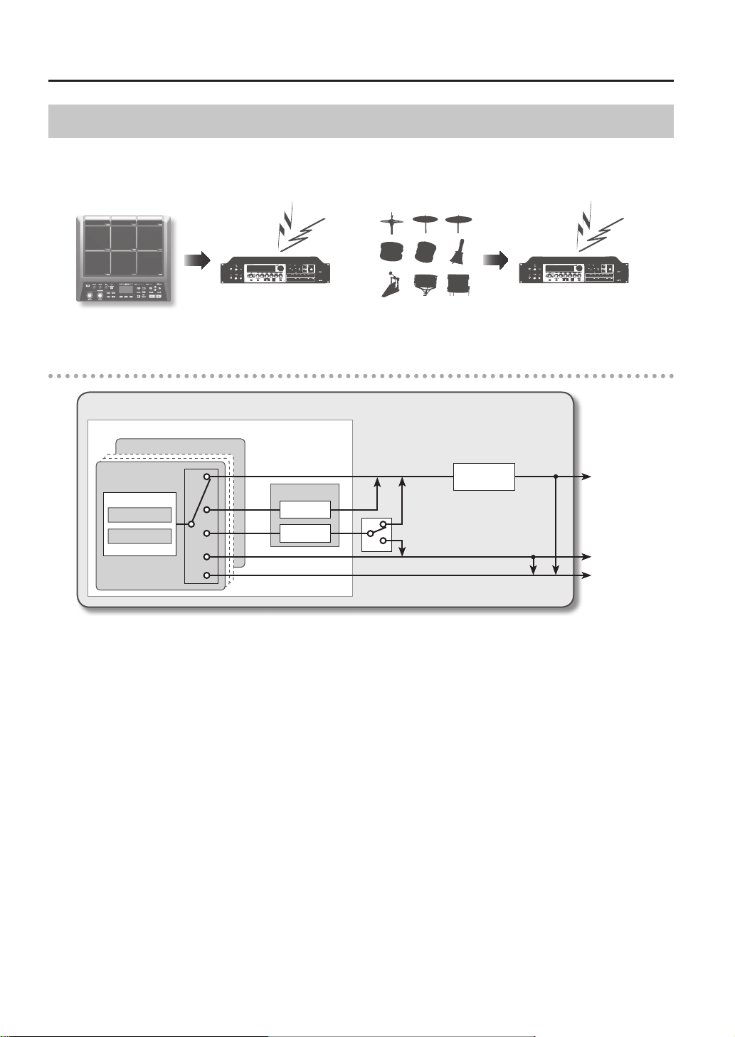
About the Eects
The SPD-SX includes a “MASTER EFFECT” processor (p. 22), which applies to all sounds being produced, and a “KIT FX” processor
(p. 23), which can be used on a per-kit basis.
Use these eects to modify and personalize the sounds as appropriate for the song or performance.
MASTER EFFECT KIT FX
Audio signal ow
SPD-SX
*1: OUTPUT (p. 43) parameter
*2: FX2 (p. 55) parameter
MASTER OUT
SUB OUT
PHONES
KIT
PAD1
KIT FX
FX1
FX2
SUB WAVE
WAVE
FS2
*1
*2
MASTER
EFFECT
Introducing the SPD-SX
Introducing the SPD-SX
7
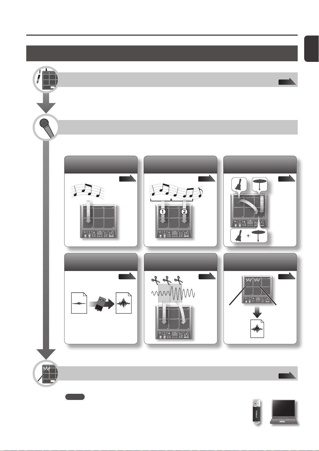
Sampling Workow
Get Ready
Connect your microphone or external audio device.
Record a Sample
The SPD-SX lets you create a sample in any one of six ways.
Use the method that’s best for your situation.
p. 34p. 32p. 29
Record your performance on
the SPD-SX
p. 38p. 36p. 35
Combine two waves into one
Sample successively to
dierent pads
Sample to one pad
Cut a wave (Chop)
Apply an eect to a wave
and resample it
Perform
Now you can perform using the waves you sampled.
MEMO
You can import sounds from a USB ash drive or your computer into the SPD-SX and
play them (p. 39).
p. 12
p. 20

8
Introducing the SPD-SX . . . . . . . . . . . . . . . . . . . . . . . . . . . . . . . 4
Things You Can Do with the SPD-SX . . . . . . . . . . . . . . . . . . 4
Overview of the SPD-SX . . . . . . . . . . . . . . . . . . . . . . . . . . . . . 5
What’s a Wave? . . . . . . . . . . . . . . . . . . . . . . . . . . . . . . . . 5
What’s a Kit? . . . . . . . . . . . . . . . . . . . . . . . . . . . . . . . . . . 5
About the Eects . . . . . . . . . . . . . . . . . . . . . . . . . . . . . . 6
Sampling Workow . . . . . . . . . . . . . . . . . . . . . . . . . . . . . . . . . 7
Get Ready . . . . . . . . . . . . . . . . . . . . . . . . . . . . . . . . . . . . . 7
Record a Sample . . . . . . . . . . . . . . . . . . . . . . . . . . . . . . 7
Perform . . . . . . . . . . . . . . . . . . . . . . . . . . . . . . . . . . . . . . . 7
Panel Descriptions . . . . . . . . . . . . . . . . . . . . . . . . . . . . . . . . . . . 10
Top Panel . . . . . . . . . . . . . . . . . . . . . . . . . . . . . . . . . . . . . . . . . . 10
Rear Panel (Connecting Your Equipment) . . . . . . . . . . . 12
Getting Ready to Play . . . . . . . . . . . . . . . . . . . . . . . . . . . . . . . . 14
Attaching to a Stand . . . . . . . . . . . . . . . . . . . . . . . . . . . . . . . 14
Using the SPD-SX with a Drum Set . . . . . . . . . . . . 14
Using the SPD-SX by Itself . . . . . . . . . . . . . . . . . . . . 14
Turning the Power On . . . . . . . . . . . . . . . . . . . . . . . . . . . . . . 15
Turning the Power On . . . . . . . . . . . . . . . . . . . . . . . . 15
Turning the Power O . . . . . . . . . . . . . . . . . . . . . . . . 15
Basic Editing Procedure . . . . . . . . . . . . . . . . . . . . . . . . . . . . 16
Using the Quick Menu . . . . . . . . . . . . . . . . . . . . . . . . . . . . . . 17
Using a USB Flash Drive. . . . . . . . . . . . . . . . . . . . . . . . . . . . . 18
Connecting Your Computer via USB . . . . . . . . . . . . . . . . . 19
Installing the USB Driver . . . . . . . . . . . . . . . . . . . . . . 19
Switching the USB Operating Mode
(USB MODE) . . . . . . . . . . . . . . . . . . . . . . . . . . . . . . . . . . 19
Connecting the SPD-SX to the Computer . . . . . . 19
Performing . . . . . . . . . . . . . . . . . . . . . . . . . . . . . . . . . . . . . . . . . . 20
Playing the Pads . . . . . . . . . . . . . . . . . . . . . . . . . . . . . . . . . . . 20
Stopping All Sounds . . . . . . . . . . . . . . . . . . . . . . . . . . 20
Using Headphones to Check Sounds . . . . . . . . . . 20
Selecting a Kit . . . . . . . . . . . . . . . . . . . . . . . . . . . . . . . . . . . . . . 21
Using the Master Eects . . . . . . . . . . . . . . . . . . . . . . . . . . . . 22
Controlling the Master Eect in Real Time . . . . . 23
Applying a Kit Eect (KIT FX SW) . . . . . . . . . . . . . . . . . . . . 23
Performing with a Click (Metronome) . . . . . . . . . . . . . . . 24
Changing the Tempo (TEMPO) . . . . . . . . . . . . . . . . . . . . . . 25
Adjusting the Pad Volume (PAD VOLUME) . . . . . . . . . . . 26
Performing with External Pads and Footswitches . . . . 27
Sampling . . . . . . . . . . . . . . . . . . . . . . . . . . . . . . . . . . . . . . . . . . . . 28
Sampling to a Single Pad (BASIC SAMPLING) . . . . . . . . 29
Successively Sampling to Multiple Pads
(MULTI PAD) . . . . . . . . . . . . . . . . . . . . . . . . . . . . . . . . . . . . . . . . 32
Combining Two Waves into One (MERGE) . . . . . . . . . . . 34
Resampling with Eects (WITH FX) . . . . . . . . . . . . . . . . . . 35
Dividing a Wave (CHOP) . . . . . . . . . . . . . . . . . . . . . . . . . . . . 36
Recording the Sound of an SPD-SX Performance
(PERFORM & RECORD) . . . . . . . . . . . . . . . . . . . . . . . . . . . . . . 38
Importing Audio Files . . . . . . . . . . . . . . . . . . . . . . . . . . . . . . . . 39
Importing Audio Files from a USB Flash Drive
(WAVE IMPORT) . . . . . . . . . . . . . . . . . . . . . . . . . . . . . . . . . . . . 39
Importing Audio Files from Your Computer . . . . . . . . . . 40
Customizing a Kit . . . . . . . . . . . . . . . . . . . . . . . . . . . . . . . . . . . . 42
Settings for the Entire Kit (KIT) . . . . . . . . . . . . . . . . . . . . . . 42
Adjusting the Kit Volume and Tempo
(COMMON) . . . . . . . . . . . . . . . . . . . . . . . . . . . . . . . . . . 42
Output Assignments (OUTPUT) . . . . . . . . . . . . . . . 43
MIDI Settings (MIDI) . . . . . . . . . . . . . . . . . . . . . . . . . . 43
Specifying How a Wave Will Sound (KIT PAD) . . . . . . . . 44
Selecting the Wave Played by a Pad (MAIN) . . . . 45
Specifying How the Wave is Sounded (MODE) . 45
Playing the Second Wave (SUB) . . . . . . . . . . . . . . . 46
Applying a Kit Eect (KIT FX) . . . . . . . . . . . . . . . . . . . . . . . . 46
Copying Parameter Settings to All Pads
(SET ALL PAD) . . . . . . . . . . . . . . . . . . . . . . . . . . . . . . . . . . . . . . 47
Assigning a Name (NAME) . . . . . . . . . . . . . . . . . . . . . . . . . . 47
Copying Kits or Pads . . . . . . . . . . . . . . . . . . . . . . . . . . . . . . . . 48
Copying a Kit . . . . . . . . . . . . . . . . . . . . . . . . . . . . . . . . . 48
Copying a Pad . . . . . . . . . . . . . . . . . . . . . . . . . . . . . . . . 48
Exchanging Pads (PAD EXCHANGE) . . . . . . . . . . . . . . . . . 49
Initializing a Kit or Pad . . . . . . . . . . . . . . . . . . . . . . . . . . . . . . 49
Initializing a Kit (KIT INIT) . . . . . . . . . . . . . . . . . . . . . 49
Initializing a Pad (PAD INIT) . . . . . . . . . . . . . . . . . . . 49
Editing a Wave . . . . . . . . . . . . . . . . . . . . . . . . . . . . . . . . . . . . . . . 50
Specifying a Wave’s Start and End
(WAVE START/END) . . . . . . . . . . . . . . . . . . . . . . . . . . . . . . . . . 50
Normalizing a Wave’s Volume (WAVE NORMALIZE) . . . 50
Adjusting the Pitch of a Wave (WAVE PITCH) . . . . . . . . . 50
Creating a Wave That Plays in Reverse
(WAVE REVERSE) . . . . . . . . . . . . . . . . . . . . . . . . . . . . . . . . . . . 51
Deleting Unwanted Regions of a Wave
(WAVE TRUNCATE) . . . . . . . . . . . . . . . . . . . . . . . . . . . . . . . . . . 51
Assigning a Category to a Wave (WAVE CATEGORY) . . 51
Organizing the Waves (RENUMBER) . . . . . . . . . . . . . . . . . 52
Copying a Wave (WAVE COPY) . . . . . . . . . . . . . . . . . . . . . . 52
Deleting a Wave (WAVE DELETE) . . . . . . . . . . . . . . . . . . . . 52
Saving a Wave to USB Memory (WAVE EXPORT) . . . . . 52
Contents

Contents
Contents
9
Overall Settings for the SPD-SX . . . . . . . . . . . . . . . . . . . . . . . 53
Sound and Performance-related Settings (SYSTEM) . . 53
Master Eect Settings (MASTER EFFECT) . . . . . . 53
Click Sound Settings (CLICK) . . . . . . . . . . . . . . . . . . 54
Input/Output Settings (AUDIO IN/OUT) . . . . . . . 55
Specifying the Kit Switching Order
(KIT CHAIN) . . . . . . . . . . . . . . . . . . . . . . . . . . . . . . . . . . 56
Using a Pad or Footswitch as a Switch
(PAD/FS CONTROL) . . . . . . . . . . . . . . . . . . . . . . . . . . . 57
Controlling Images (VISUAL CONTROL) . . . . . . . . 57
Initializing the System (SYSTEM INIT) . . . . . . . . . . . . . . . . 58
Display and Pad Settings (SETUP) . . . . . . . . . . . . . . . . . . . 59
Display Brightness and Indicator Settings
(LCD/LED) . . . . . . . . . . . . . . . . . . . . . . . . . . . . . . . . . . . . 59
Pad Sensitivity Adjustment (PAD SENS) . . . . . . . . 60
External Pad Settings (TRIG IN) . . . . . . . . . . . . . . . . 62
Footswitch Settings (FOOT SW) . . . . . . . . . . . . . . . 63
MIDI Settings (MIDI) . . . . . . . . . . . . . . . . . . . . . . . . . . 63
Other Settings (OPTION) . . . . . . . . . . . . . . . . . . . . . . 63
Initializing the Setup Parameters (SETUP INIT) . . . . . . . 64
Other Convenient Functions (UTILITY) . . . . . . . . . . . . . . 64
Viewing the Wave List (WAVE LIST) . . . . . . . . . . . . 64
Importing an Audio File from a USB Flash
Drive (WAVE IMPORT) . . . . . . . . . . . . . . . . . . . . . . . . 65
Loading Data from a USB Flash Drive
(LOAD (USB MEMORY)) . . . . . . . . . . . . . . . . . . . . . . . 65
Saving Data to a USB Flash Drive
(SAVE (USB MEMORY)) . . . . . . . . . . . . . . . . . . . . . . . . 66
Viewing Information About the SPD-SX Itself
(INFORMATION) . . . . . . . . . . . . . . . . . . . . . . . . . . . . . . 66
Connecting an External MIDI Device . . . . . . . . . . . . . . . . . . 67
MIDI Settings for Each Pad (MIDI) . . . . . . . . . . . . . . . . . . . 67
MIDI Settings for the Entire SPD-SX (MIDI) . . . . . . . . . . . 68
Appendix . . . . . . . . . . . . . . . . . . . . . . . . . . . . . . . . . . . . . . . . . . . . 69
Troubleshooting . . . . . . . . . . . . . . . . . . . . . . . . . . . . . . . . . . . 69
Error Message List . . . . . . . . . . . . . . . . . . . . . . . . . . . . . . . . . . 70
Specications . . . . . . . . . . . . . . . . . . . . . . . . . . . . . . . . . . . . . . 71
Index . . . . . . . . . . . . . . . . . . . . . . . . . . . . . . . . . . . . . . . . . . . . . . . . 72
USING THE UNIT SAFETY . . . . . . . . . . . . . . . . . . . . . . . . . . . . . 74
IMPORTANT NOTES . . . . . . . . . . . . . . . . . . . . . . . . . . . . . . . . . . 75
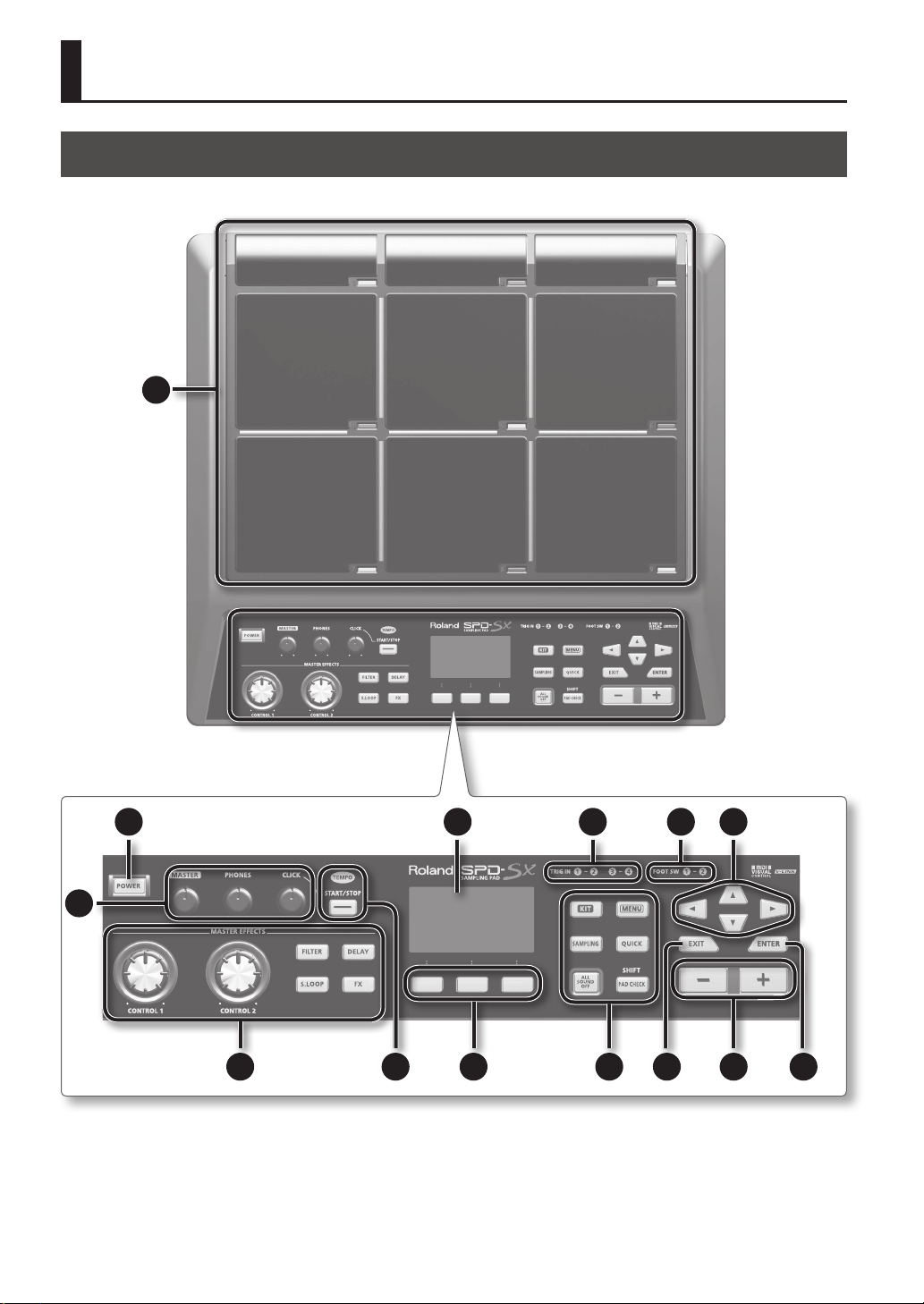
Top Panel
10
Panel Descriptions
1
9 10
12 1113
3
2 14
4 5 6 87
Panel Descriptions
Panel Descriptions
11
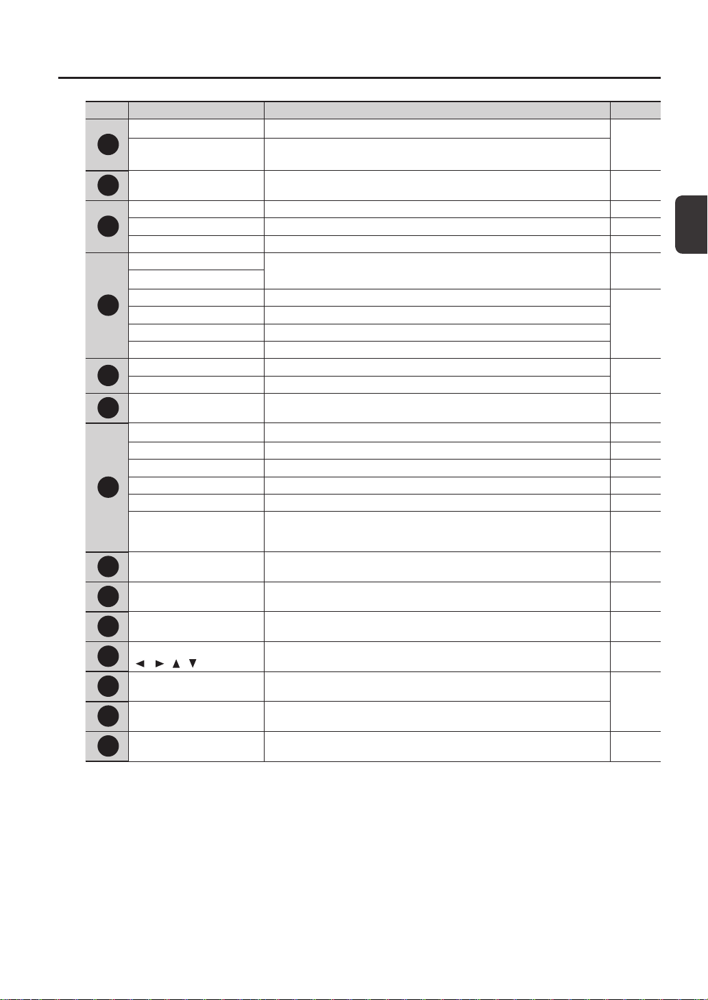
Number Name Explanation Page
1
Pad 1–9 Play pads 1–9 by playing them with sticks.
p. 20
Pad indicator 1–9
These indicators are located at the lower right of each pad.
They will light when the pad is struck.
2
[POWER] button Turns the power on/o. p. 15
3
[MASTER] knob Adjusts the volume of the MASTER OUT jacks. p. 15
[PHONES] knob Adjusts the volume of the PHONES jack. p. 15
[CLICK] knob Adjusts the volume of the click. p. 24
4
[CONTROL 1] knob
Modies the master eects. p. 23
[CONTROL 2] knob
[FILTER] button Turns the lter on/o.
p. 22
[DELAY] button Turns the delay on/o.
[S.LOOP] button Turns the short looper on/o.
[FX] button Turns FX on/o.
5
TEMPO indicator This will light in time with the performance tempo.
p. 24
[START/STOP] button Turns the click start/stop.
6
Function buttons
These execute the functions shown at the bottom of the display.
In this manual they are called, from left to right, the [F1], [F2], and [F3] buttons.
-
7
[KIT] button Displays the top screen. p. 21
[MENU] button Accesses various functions, such as overall settings for the entire SPD-SX. p. 16
[SAMPLING] button Captures a sample. p. 28
[QUICK] button Accesses a quick menu (QUICK MENU) specic to each screen. p. 17
[ALL SOUND OFF] button Stops all currently playing sounds. p. 20
[PAD CHECK] button
Auditions the sound of the struck pad through headphones.
This button is also used in conjunction with other buttons to perform various
operations.
p. 20
8
[EXIT] button
Returns you to the previous screen.
This button is also used to cancel an operation.
-
9
[-] [+] buttons Use these to change kit numbers, wave numbers, or parameter values. -
10
[ENTER] button When this button is blinking, press it to execute the operation. -
11
Cursor buttons
[ ] [ ] [ ] [ ]
Use these buttons to move the cursor. -
12
FOOT SW indicators
These will light when a signal is received from a footswitch connected to the FOOT
SW jack.
p. 27
13
TRIG IN indicators
These will light when a signal is received from an external pad or pedal connected to
the TRIG IN jacks.
14
Display Kit names, wave names, and settings are shown here. p. 21
Panel Descriptions
12
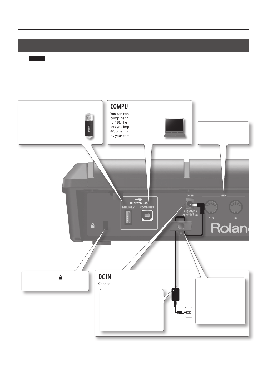
Rear Panel (Connecting Your Equipment)
COMPUTER connector
You can connect your
computer here via a USB cable
(p. 19). The included software
lets you import audio les (p.
40) or sample the sounds played
by your computer (p. 29).
USB MEMORY connector
You can connect a USB ash drive
(sold separately) here (p. 18). This allows
you to import audio les (p. 39), or save
SPD-SX waves and settings to your
USB ash drive (p. 66).
DC IN jack
Connect the included AC adaptor here.
To prevent the inadvertent
disruption of power to your
unit (should the plug be
pulled out accidentally),
and to avoid applying
undue stress to the DC IN
jack, anchor the power cord
using the cord hook, as
shown in the illustration.
NOTE!
• To prevent malfunction and/or damage to speakers or other devices, always turn down the volume, and turn o the power
on all devices before making any connections.
• When connection cables with resistors are used, the volume level of equipment connected to the inputs (AUDIO IN jacks)
may be low. If this happens, use connection cables that do not contain resistors.
Security slot ( )
http://www.kensington.com/
MIDI connectors
MIDI devices can be
connected here (p. 67).
Place the AC adaptor so the side
with the indicator (see illustration)
faces upwards and the side
with textual information faces
downwards.
The indicator will light when you
plug the AC adaptor into an AC
outlet.
Panel Descriptions
Panel Descriptions
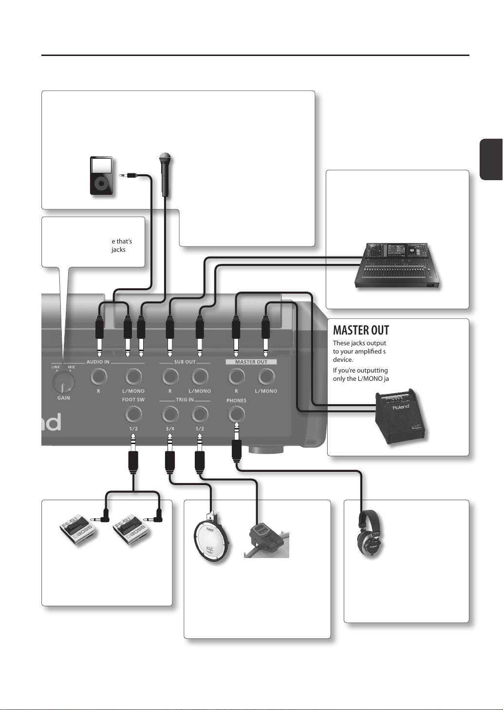
13
AUDIO IN jacks
When you want to sample, connect your microphone or digital audio player to these jacks.
The sound that’s input to these jacks will be output from the MASTER OUT jacks and the
PHONES jack.
PHONES jack
Headphones can be connected here.
Sound will still be output from the SUB
OUT jacks and MASTER OUT jacks even
if headphones are connected.
MASTER OUT jacks
These jacks output the sound. Connect them
to your amplied speakers or recording
device.
If you’re outputting in monaural, connect to
only the L/MONO jack.
FOOT SW jack
A footswitch (FS-5U, FS-6; sold separately)
can be connected here and used to
control a variety of things (p. 27, p. 57).
TRIG IN jacks
External pads (PD series; sold separately)
or acoustic drum triggers (RT series; sold
separately) can be connected here (p. 27).
* To make the connection, use the cable that
came with the product you’re using.
[GAIN] knob
This adjusts the volume that’s
input to the AUDIO IN jacks
(p. 29).
SUB OUT jacks
Connect them to your mixer or audio system.
These jacks output the sound of only the pads
you’ve specied (p. 43).
If you’re outputting in monaural, connect to
only the L/MONO jack.
* Use a monaural dynamic microphone.
The SPD-SX does not support condenser
microphones.
* Howling could be produced depending
on the location of microphones relative
to speakers. This can be remedied by:
1. Changing the orientation of the
microphone(s).
2. Relocating microphone(s) at a greater
distance from speakers.
3. Lowering volume levels.
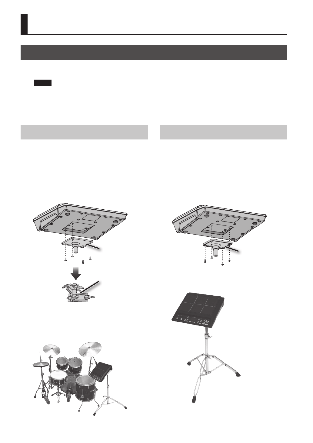
Attaching to a Stand
If you want to attach the SPD-SX to a stand, use an all-purpose clamp (APC-33; sold separately) or a pad stand (PDS-10; sold
separately).
NOTE!
• You must use the screws on the bottom panel of the SPD-SX. Using any other screws may cause malfunction.
• When turning the unit upside–down, get a bunch of newspapers or magazines, and place them under the four corners
or at both ends to prevent damage to the buttons and controls. Also, you should try to orient the unit so no buttons or
controls get damaged.
• When turning the unit upside–down, handle with care to avoid dropping it, or allowing it to fall or tip over.
14
Getting Ready to Play
Using the SPD-SX with a Drum Set
If you want to attach the SPD-SX to a cymbal stand and
play it in conjunction with V-Drums or a drum set, secure
it using an all-purpose clamp (APC-33; sold separately).
Use the screws on the bottom panel of the SPD-SX to
attach the stand holder of the all-purpose clamp as
shown in the illustration. Then attach the SPD-SX to the
all-purpose clamp.
* Do not use the screws included with the all-purpose
clamp.
All-purpose clamp
Stand holder
* The all-purpose clamp can accommodate a rod with a
diameter in the range of 10.5–30 mm.
Example setup
Using the SPD-SX by Itself
If you’re using the SPD-SX on its own, use a pad stand
(PDS-10; sold separately).
Using the screws on the bottom of the SPD-SX, attach
the PDS-10 stand holder as shown in the illustration.
Then attach the SPD-SX to the pad stand.
For details on how to assemble the pad stand and use
the pad holder, refer to the owner’s manual of the pad
stand.
* Do not use the screws included with the pad stand.
Stand holder
Example setup
Getting Ready to Play
Getting Ready to Play
15
Turning the Power On
NOTE!
* Once the connections have been completed (p. 12), turn on power to your various devices in the order specied. By turning
on devices in the wrong order, you risk causing malfunction and/or damage to speakers and other devices.
* Before switching the power on/o, always be sure to turn the volume down. Even with the volume turned down, you
might hear some sound when switching the power on/o. However, this is normal and does not indicate a malfunction.
• With the factory settings, the SPD-SX’s power will automatically be switched o 4 hours after you stop playing or operating
the unit. If you don’t want the power to turn o automatically, change the AUTO OFF setting to “OFF” as described on p. 63.
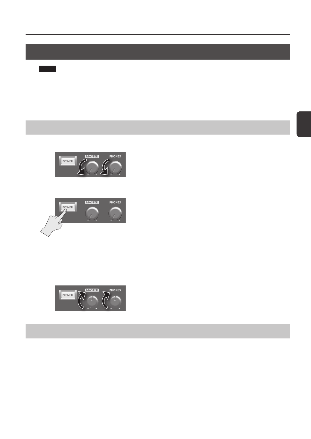
Turning the Power On
1. Minimize the volume by turning the [MASTER] knob and [PHONES] knob all the way to the left.
2. Press the [POWER] button.
* This unit is equipped with a protection circuit. A brief interval (a few seconds) after power up is required before the unit will
operate normally.
3. Turn on the power of your speakers.
4. Use the [MASTER] knob and [PHONES] knob to adjust the volume appropriately.
Turning the Power O
1. Minimize the volume of the SPD-SX and your speakers.
2. Turn o the power of your speakers.
3. Hold down the [POWER] button until the screen goes blank.
Getting Ready to Play
16
Basic Editing Procedure
Here’s the basic procedure for using the buttons and knobs to edit the SPD-SX’s settings.
15
2 34 4
2 3 4
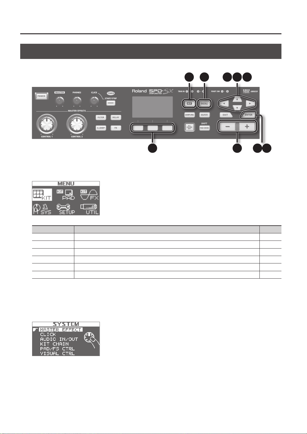
1. Press the [MENU] button.
The MENU screen will appear.
MENU Explanation Page
KIT Make settings for an entire kit. p. 42
KIT PAD Specify how the waves of each pad will sound. p. 44
KIT FX Make settings for the kit eects. p. 46
SYS (SYSTEM) Make overall sound and performance settings for the entire SPD-SX. p. 53
SETUP Make overall display, pad, and MIDI-related settings for the entire SPD-SX. p. 59
UTIL (UTILITY) View information about the SPD-SX, and transfer data with a USB ash drive. p. 64
2. Use the cursor buttons to select the desired menu item, and then press the [ENTER] button.
The edit screen for the selected menu item will appear.
If you selected “KIT,” “KIT PAD,” or “KIT FX” from the menu, proceed to step 4.
Example: The SYSTEM screen
Getting Ready to Play
Getting Ready to Play
17
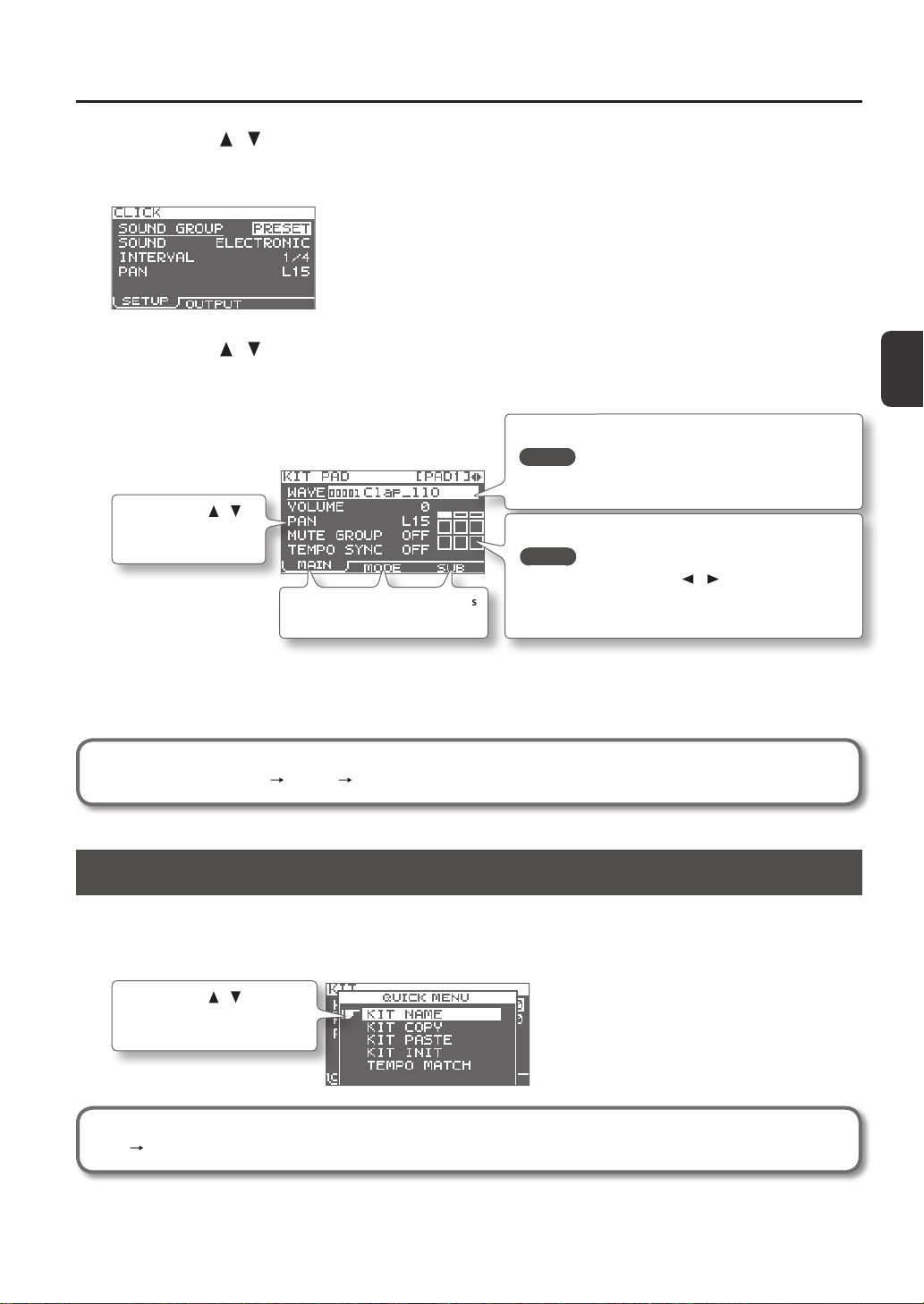
3. Use the cursor [ ] [ ] buttons to select the desired item, and then press the [ENTER] button.
The edit screen for the selected item will appear.
Example: The CLICK screen
4. Use the cursor [ ] [ ] buttons to select the parameter that you want to edit, and use the [-] [+] buttons to
edit the value.
Example: The KIT PAD screen
Use the cursor [ ] [ ]
buttons to select a
parameter to edit.
Use the [-] [+] buttons to edit the parameter.
MEMO
By holding down the [SHIFT] button and using the [-] [+]
buttons, you can select waves in steps of 10.
Use the function buttons to access
the corresponding edit screens.
To select the pad that you want to edit, play that pad.
MEMO
• You can also use the cursor [ ] [ ] buttons to select a pad.
• If desired, you can make settings so that a pad will not be
selected for editing when you play it (p. 63).
Pressing the [EXIT] button will take you back to the previous screen.
5. When you’ve nished making settings, press the [KIT] button to return to the top screen.
The SPD-SX’s settings are saved when you turn o the power; you don’t need to take any action to save the settings.
In this manual, the process of navigating from the MENU screen to select SYSTEM and then select CLICK is
abbreviated as “MENU SYSTEM CLICK.”
Using the Quick Menu
You can rapidly select menus relevant to the screen that’s displayed by using the Quick menu.
Press the [QUICK] button to display the Quick menu.
Example: The quick menu in the KIT screen (p. 42)
Use the cursor [ ] [ ] buttons
to select an item, and press the
[ENTER] button to conrm.
In this manual, the operation of accessing the quick menu and selecting KIT NAME is abbreviated as “QUICK MENU
KIT NAME.”
Getting Ready to Play
18
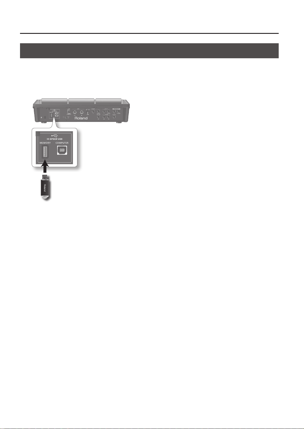
Using a USB Flash Drive
If a USB ash drive (separately sold) is connected to the SPD-SX, you’ll be able to do the following things.
• Import audio les from the USB ash drive (p. 39).
• Use the USB ash drive to save or load the SPD-SX’s waves or settings (p. 65, p. 66).
1. Connect your USB ash drive to the USB MEMORY connector.
USB ash drive
* Carefully insert the USB ash drives all the way in—until it is rmly in place.
* Use USB Flash Memory sold by Roland. We cannot guarantee operation if other USB ash drive is used.
Getting Ready to Play
Getting Ready to Play
19
Connecting Your Computer via USB
If you use a commercially available USB cable to connect the SPD-SX’s COMPUTER connector to a USB port on your computer,
you’ll be able to do the following things.
SPD-SX Wave Manager
You can use the “SPD-SX Wave Manager” on the included CD-ROM to import audio les from your computer (p. 40).
USB Audio
Sounds played by your computer can be sampled (p. 29), or sounds played by the SPD-SX can be recorded as audio on your
computer.
USB MIDI
Performance data (MIDI data) from the SPD-SX can be recorded into DAW software on your computer.
Installing the USB Driver
In order to use USB audio and USB MIDI functionality, you must rst install the USB driver. (SPD-SX Wave Manager can be used
without installing the USB driver.)
1. Install the USB driver into your computer.
The USB driver is provided on the included CD-ROM.
For the operating requirements, refer to “ReadmeEN.txt” on the CD-ROM.
The procedure for installing the USB driver will depend on the system you’re using, so carefully read the “ReadmeEN.txt” le on
the CD-ROM before you proceed.
Switching the USB Operating Mode (USB MODE)
This setting species how operation will occur when the SPD-SX is connected via USB to your computer. For details, refer to
“USB MODE” (p. 63).
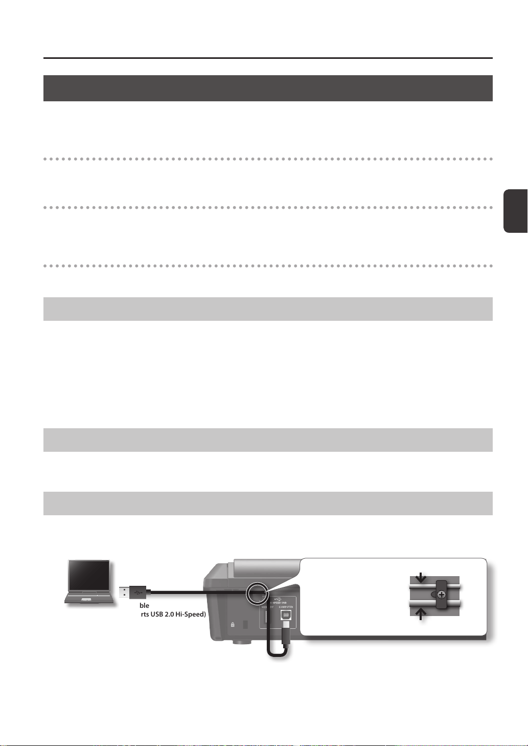
Connecting the SPD-SX to the Computer
1. Use a commercially available USB cable to connect the SPD-SX ‘s COMPUTER connector to a USB port on your
computer, you’ll be able to do the following things.
Computer
USB cable
(Supports USB 2.0 Hi-Speed)
Use the rear panel cable
hook to secure the USB cable
as shown in the illustration
at right. This will prevent USB
communication errors from
being caused by vibration
when the SPD-SX is struck.
For a thin USB cable
For a thick USB cable
* Use a USB cable that supports USB 2.0 Hi-Speed.
* Turn on the SPD-SX’s power before you start up the DAW software on your computer. Do not turn the SPD-SX’s power on/
o while your DAW software is running.
20
Performing
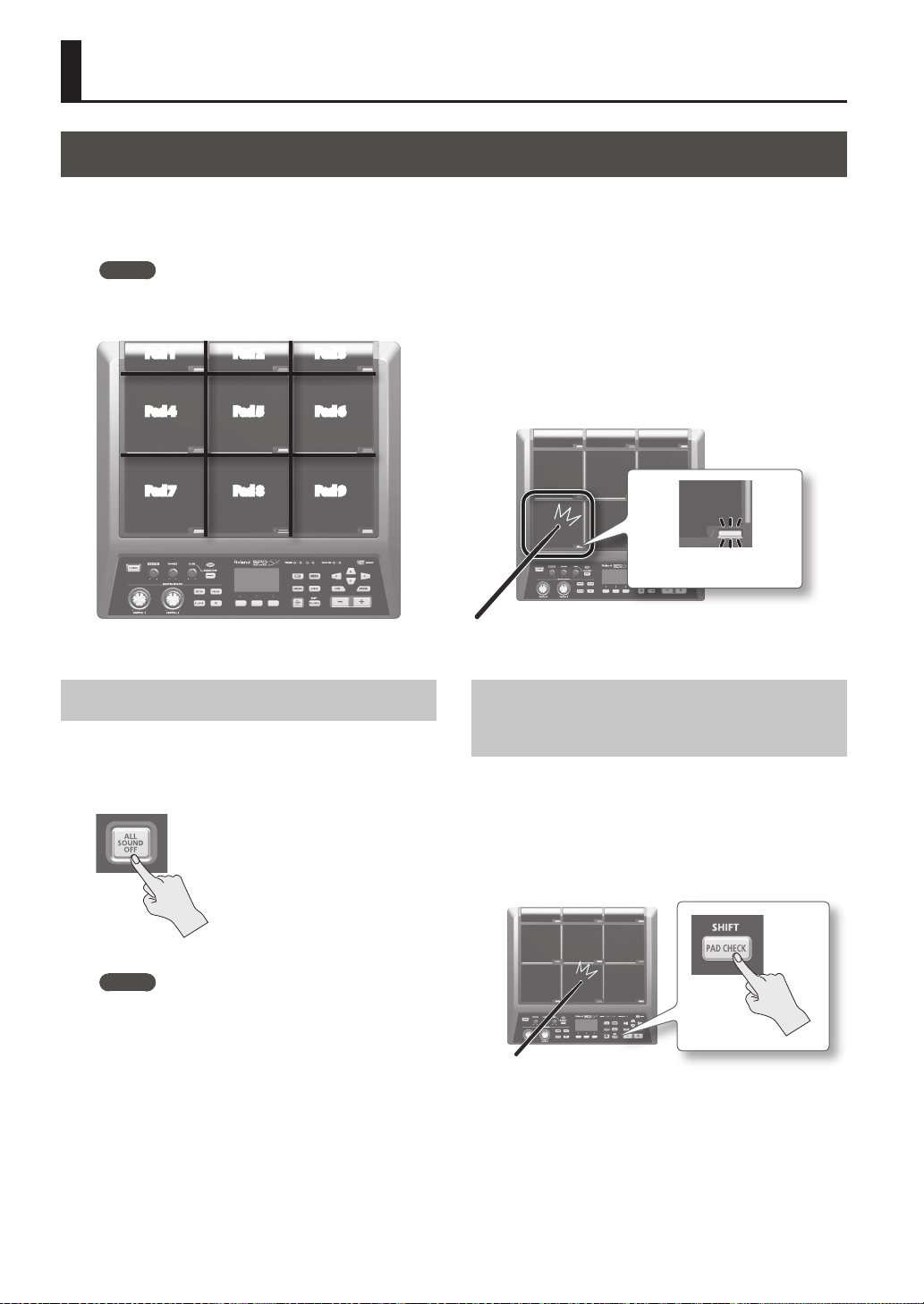
Playing the Pads
The SPD-SX has nine onboard pads (pads 1–9).
When you play a pad, the indicator of that pad will light.
* Though you can play with your hands, the SPD-SX is designed to respond optimally when played with sticks.
MEMO
• Use the shoulder of the stick to play pads 1–3.
• You can specify how the indicators for the pads will light (p. 59).
Pad 4
Pad 7
Pad 1 Pad 2 Pad 3
Pad 8
Pad 6
Pad 9
Pad 5
Example: When you play pad 7
Pad indicator 7 will light
Stopping All Sounds
Here’s how to stop all currently playing sounds.
1. To stop all sounds, press the [ALL SOUND OFF]
button.
MEMO
You can also stop all currently playing sounds by
playing a pad or pressing a footswitch (p. 57).
Using Headphones to Check
Sounds
If desired, you can check the sounds only through
headphones. This is useful during a live performance
when you want to verify sound assigned to a pad
without anyone else hearing it.
1. While holding down the [PAD CHECK] button,
play the pad whose sound you want to check.
Performing
Performing
21
Selecting a Kit
Now, try selecting a kit (p. 5) and playing it.
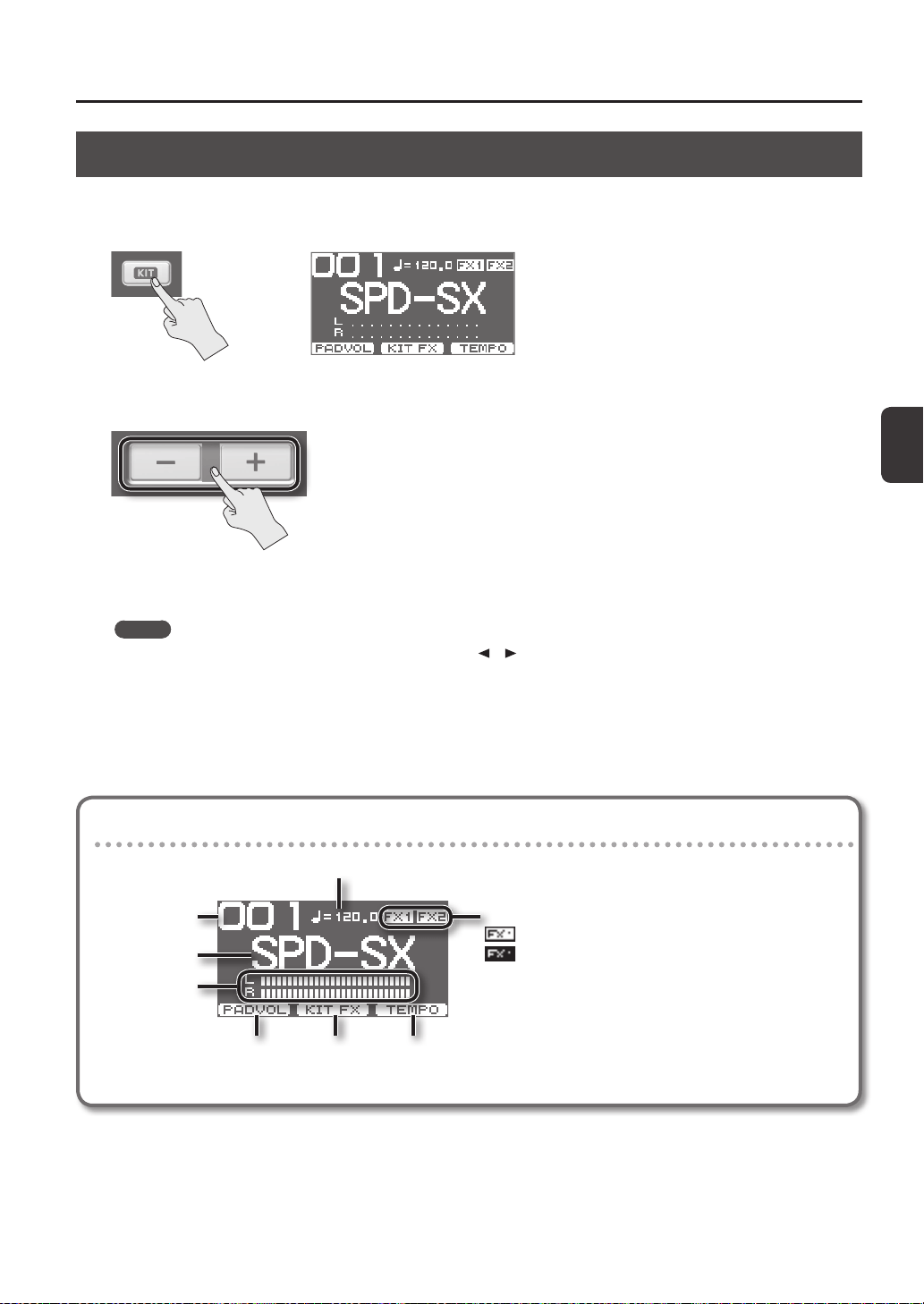
1. Press the [KIT] button to access the top screen.
2. Use the [-] [+] buttons to select a kit.
3. Try selecting various kits and playing them.
MEMO
• By holding down the [SHIFT] button and using the cursor [
] [ ] buttons, you can select kits in steps of 10.
• You can move rapidly through the kits by holding down the [-] button and pressing the [+] button, or by holding down the
[+] button and pressing the [-] button.
• You can register the order in which you want to switch kits This is called a path Chain (p. 56).
• You can freely customize a kit by assigning the sounds you like to the pads, and by applying eects (p. 42).
• You can also switch kits by playing a pad or pressing a footswitch (p. 57).
Information shown in the top screen
Performance tempo
Kit name
Kit number
Level meter
Kit eect (p. 46) on/o status
Pad volume
adjustment (p. 26)
Kit eect on/o
(p. 23)
Performance tempo
setting (p. 25)
: FX1 is on
: FX1 is o
Performing
22
Top screen quick menu
In the top screen, pressing the [QUICK] button will display the following quick menu.
Menu Explanation Page
CHAIN ON/OFF Turn the kit chain function on/o. p. 56
KIT CHAIN Jump to the KIT CHAIN screen. p. 56
MASTER EFFECT Jump to the MASTER EFFECT screen. p. 53
PAD COPY Copy a pad. p. 48
PAD PASTE Paste a pad. p. 48
PAD EXCHANGE Exchange pads. p. 49
KIT NAME Name a kit. p. 47
KIT COPY Copy a kit. p. 48
KIT PASTE Paste a kit. p. 48
PAD LOCK Turn PAD LOCK on/o. p. 63
VISUAL CTRL Turn VISUAL CTRL SW on/o. p. 57
LCD/LED Jump to the LCD/LED screen. p. 59
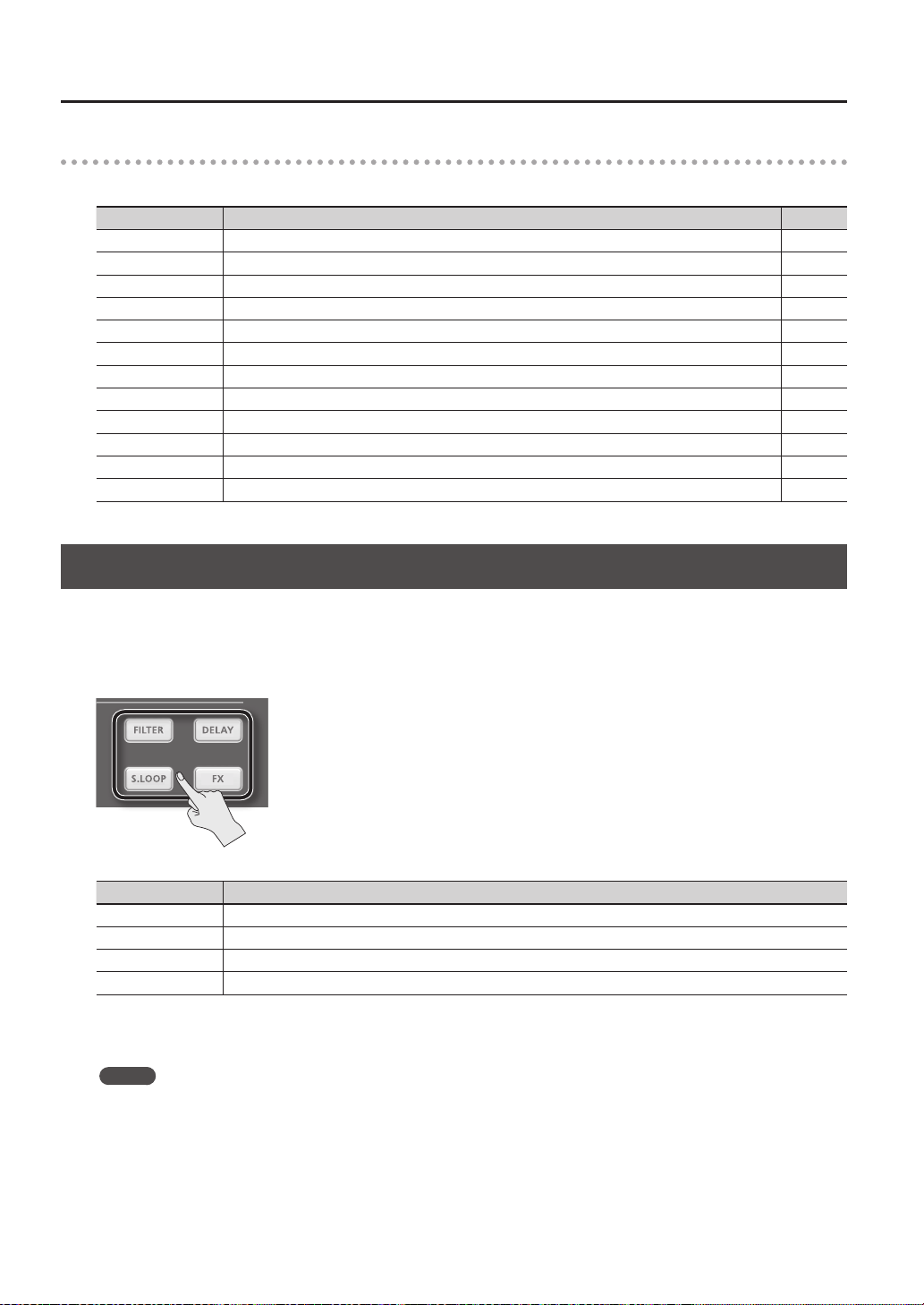
Using the Master Eects
Try using a master eect (p. 6) which will aect all sounds in the current kit.
1. Play the pads to produce sound.
2. Press the button for the master eect that you want to use.
Button Explanation
[FILTER] button Applies a lter eect.
[DELAY] button Applies a delay eect.
[S.LOOP] button Loops a short region of the currently heard sound (Short looper).
[FX] button The eect selected from the eect types will be applied.
The button you pressed will light, and the master eect will turn on.
* Only one master eect can be applied at a time.
MEMO
You can edit the settings of the master eect (p. 53).
Performing
Performing
23
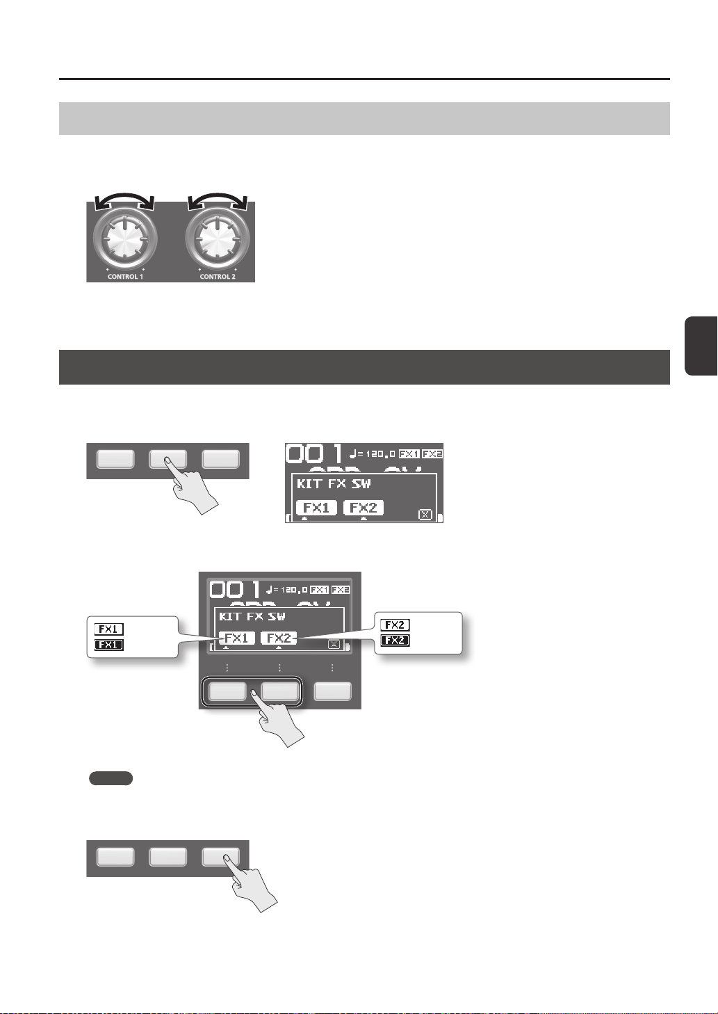
Controlling the Master Eect in Real Time
Use the [CONTROL 1] knob or [CONTROL 2] knob as follows.
1. While you perform, turn the [CONTROL 1] knob or [CONTROL 2] knob.
When you turn a knob, a change will occur depending on the master eect that’s selected.
For example, if a lter is selected, turning a knob would change the frequency response or vary the eect’s depth.
Applying a Kit Eect (KIT FX SW)
Try applying a kit eect (p. 6) to your performance.
1. In the top screen, press the [F2] (KIT FX) button.
2. Press the [F1] (FX1) button or the [F2] (FX2) button to turn the kit eect on.
: FX1 is on
: FX1 is o
: FX2 is on
: FX2 is o
MEMO
In KIT FX (p. 46) you can turn the kit eects on/o and edit their settings.
3. Press the [F3] (X) button to return to the top screen.
Performing
24
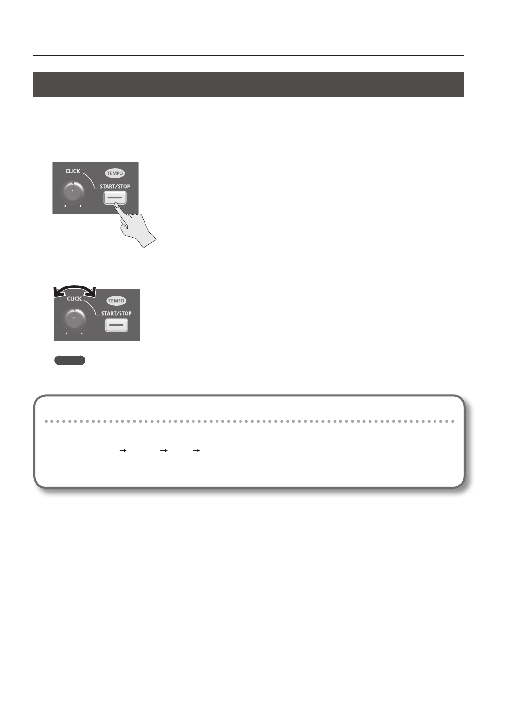
Performing with a Click (Metronome)
Performing with a click sound ensures that you’re playing at the correct tempo.
1. Press the [START/STOP] button.
The [START/STOP] button will light.
A click will sound at the tempo, and the TEMPO indicator will blink
2. Turn the [CLICK] knob to adjust the volume of the click sound.
MEMO
You can change the type of click sound (p. 54).
Settings for the Click Sound
Species the jacks from which the click sound will be output (headphones only/master out etc.).
1. Choose MENU
SYSTEM CLICK OUTPUT.
2. Set the output destination (p. 54).
Performing
Performing
25
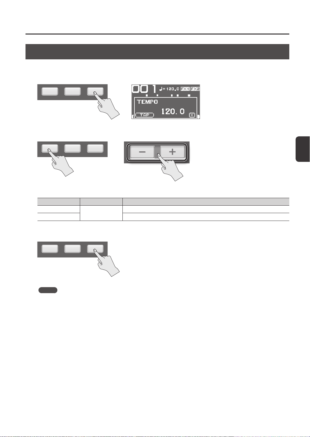
Changing the Tempo (TEMPO)
Here’s how to adjust the tempo.
1. In the top screen, press the [F3] (TEMPO) button.
2. Specify the tempo.
Button Value Explanation
[-] [+] button
20.0–260.0
Specify the tempo.
[F1] (TAP) button Specify the tempo by repeatedly pressing the button at the desired timing.
3. Press the [F3] (X) button to return to the top screen.
MEMO
You can use the KIT TEMPO (p. 54) setting to specify a tempo for each kit.
When you select a kit, the tempo will change to the tempo specied by the KIT TEMPO setting.
Performing
26
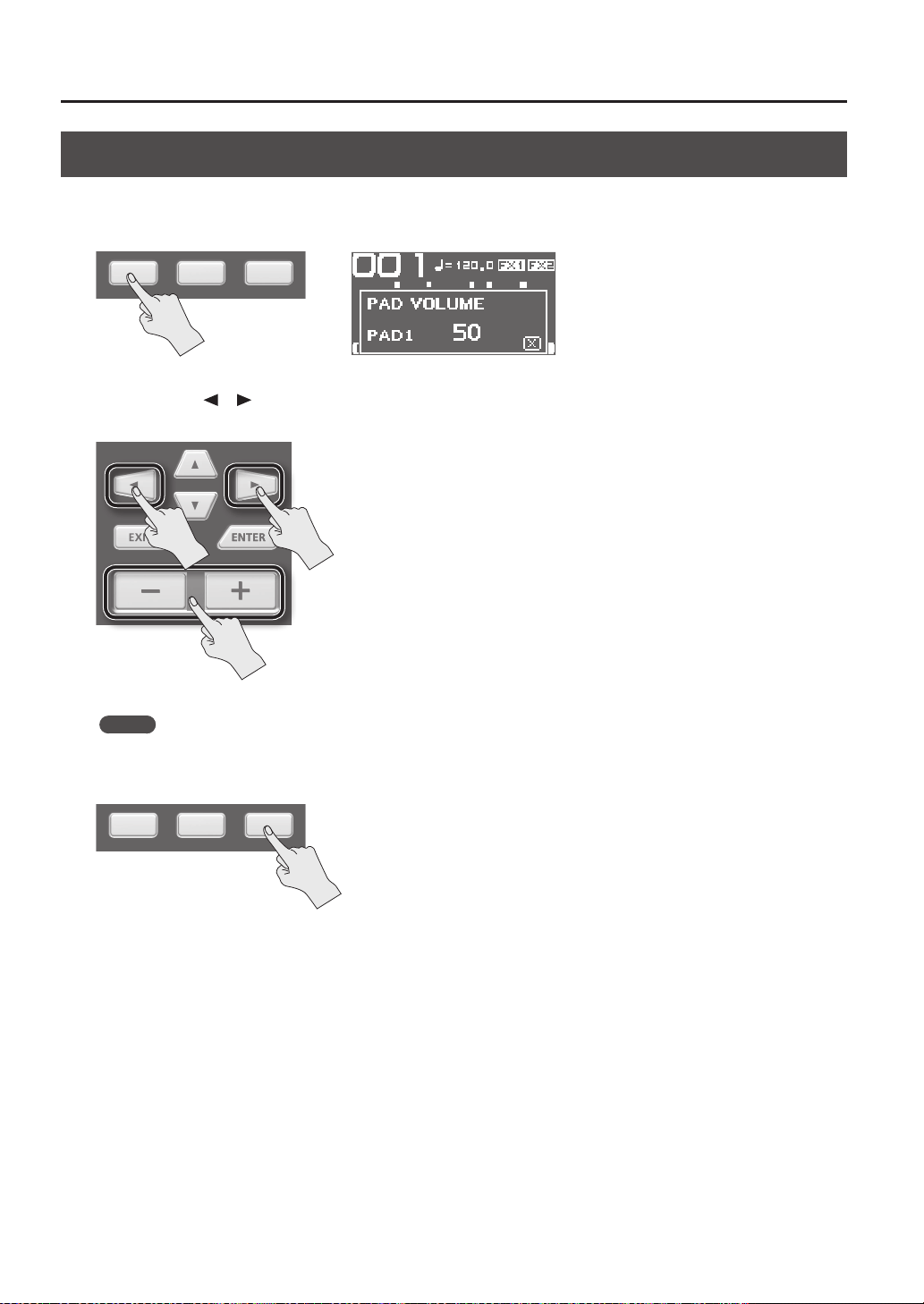
Adjusting the Pad Volume (PAD VOLUME)
You can adjust the volume of each pad.
1. In the top screen, press the [F1] (PADVOL) button.
2. Use the cursor [ ] [ ] buttons to select the pad whose volume you want to adjust, and use the [-] [+]
buttons to adjust its volume.
MEMO
You can also use the VOLUME (p. 45) setting to adjust the volume of each pad.
3. Press the [F3] (X) button to return to the top screen.
Performing
Performing
27
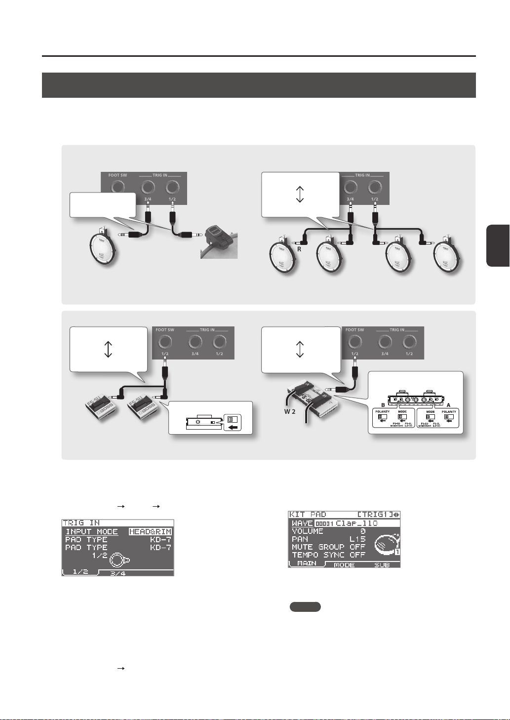
Performing with External Pads and Footswitches
You can assign waves to external pads (PD series; sold separately), acoustic drum triggers (RT series; sold separately), and
footswitches (FS-5U, FS-6; sold separately), and perform using them.
Some typical example connections are shown in the illustrations below.
1. Connect your external pads to the TRIG IN jacks.
Connect your footswitch to the FOOT SW jack.
2. Choose MENU
SETUP TRIG IN.
Footswitches connected to the FOOT SW jack do not
require EXT PAD settings. Proceed to step 4.
3. Set the parameters as appropriate for the type of
external pad you’ve connected (p. 62).
4. Select the kit that you want to play (p. 21).
5. Choose MENU
KIT PAD.
6. Play an external pad to access the KIT PAD screen
for the external pad.
To make settings for a footswitch, press the footswitch.
7. Specify the wave and volume (p. 44).
MEMO
Instead of using an external pad or footswitch to play
sounds, you can also use it to change kits or turn a kit
eect on/o (p. 57).
FOOT SW 1FOOT SW 2
White
Connecting an FS-5U
Stereo 1/4” phone type
1/4” phone type x 2
Red
POLARITY switch
Connecting an FS-6
Stereo 1/4” phone type
Stereo 1/4” phone type
FOOT SW 1
FOOT SW 2
MODE/POLARITY switch
TRIG IN 1TRIG IN 2TRIG IN 3TRIG IN 4
Connecting two external pads to one TRIG IN jack
White White
Red Red
Stereo 1/4” phone type
1/4” plug x 2
Connecting external pads or acoustic drum
triggers
TRIG IN 1
TRIG IN 2
TRIG IN 3
TRIG IN 4
Cable included
with each product
* The FS-5L cannot be used.
* If you use a mono cable to connect a single FS-5U, it will operate as FOOT SW 1.
* If you connect two
external pads to one
TRIG IN jack, only head
shots will be available.
You could connect a cymbal pad (CY series; sold separately) or a kick trigger pad (KD series; sold separately) to a TRIG IN jack.
28
Sampling
You can create waves by sampling sounds.
The SPD-SX provides six dierent methods of sampling.
Sampling method Explanation Page
BASIC SAMPLING Sample to a single pad. p. 29
MULTI PAD Successively sample to multiple pads. p. 32
MERGE Combine two waves into one. p. 34
WITH FX Apply an eect to a wave and resample it. p. 35
CHOP Cut a wave into slices. p. 36
PERFORM & RECORD Record the sound of your SPD-SX performance. p. 38
Sampling time
The SPD-SX allows you to sample approximately 180 minutes of stereo or approximately 360 minutes of monaural sound into
internal memory (including the preload waves).
MEMO
• You can check the sampling time that remains (p. 66).
• The amount of time over which sampling can take place at one time with MULTI PAD is equivalent to approximately one-
half of the available time that remains for all sampling.
Sampling setup screen quick menu
In the sampling setup screen of BASIC SAMPLING, MULTI PAD, WITH FX, or PERFORM & RECORD, pressing the [QUICK] button
will display the following quick menu.
Menu Explanation
STEREO SW If this option is selected, stereo sampling will occur. If this option is not selected, monaural sampling will occur.
* In the sampling preparation screens for MERGE and CHOP, a Quick menu is not displayed.

Sampling
Sampling
29
Sampling to a Single Pad (BASIC SAMPLING)
Here’s how to sample sound from a microphone or audio device to just a single pad.
Preparations for sampling
1. Connect your sampling source (microphone or audio device) (p. 12).
Sampling from your computer
* The USB driver must be installed in your computer (p. 19).
1. Set the MENU
SETUP OPTION USB MODE parameter to “AUDIO/MIDI.”
2. Use a commercially available USB cable to connect the SPD-SX’s COMPUTER connector to your
computer (p. 19).
2. Set the input level appropriately for the device that’s connected.
Microphone
Computer
Digital audio player, etc.
Set the [GAIN] knob on the rear panel
to the MIC position.
Set the [GAIN] knob on the rear panel to
the LINE position.
Set the input level by adjusting the volume of the playback
software on your computer.
MEMO
In order to sample at the best audio quality, we recom-
mend that you set the volume of your playback software
as high as possible.
3. Press the [SAMPLING] button to access the SAMPLING screen.
4. Use the cursor [
] [ ] buttons to select “BASIC,” and press the [ENTER] button.
The sampling setup screen will appear.
Sampling
30
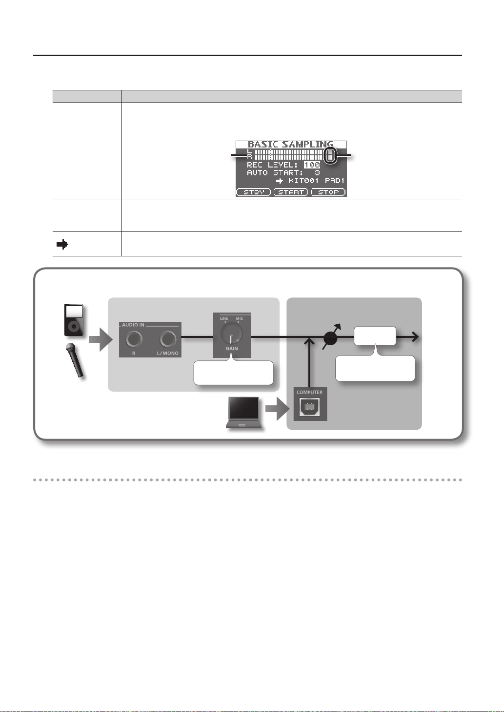
5. Use the cursor buttons and the [-] [+] buttons to make settings for sampling.
Parameter Value Explanation
REC LEVEL 0–100
Adjusts the volume at which sampling will occur.
Produce sound on the device that’s connected to the SPD-SX, and adjust the volume until it’s
as high as you can get it without causing the level overload indication to appear.
Level overload indicationLevel meter
AUTO START OFF, 1–15
When you press the [F2] (START) button, sampling will begin the moment that the input
signal exceeds the level you specied here.
If this is “OFF,” sampling will begin the moment you press the [F2] (START) button.
KIT001–100, PAD1–9
Species the kit and pad to which the sampled wave will be assigned.
* You can only select an empty pad, one which has no wave assigned to it.
Signal ow
AUDIO IN jacks
REC LEVEL
[GAIN] knob
Analog signal Digital signal
Level meter
Adjust to avoid the level
overload indication
Adjust appropriately for
the connected device
COMPUTER connector
Start sampling
6. Press the [F1] (STBY) button.
The sampling standby screen will appear.
7. Start sampling.
If you set AUTO START “OFF” in step 5
Sampling will begin when you press the [F2] (START) button. Produce sound on the device that’s connected to the SPD-SX.
While sampling is taking place, the screen will indicate “NOW SAMPLING...”
If you set AUTO START to anything other than “OFF” in step 5
Produce sound on the device that’s connected to the SPD-SX; sampling will begin when the input signal exceeds the level
specied by AUTO START.
While sampling is occurring, the screen will indicate “NOW SAMPLING...”
Sampling
Sampling
31
8. Press the [F3] (STOP) button at the moment you want to stop sampling.
The sampling result screen will appear.
Saving the sampled waves
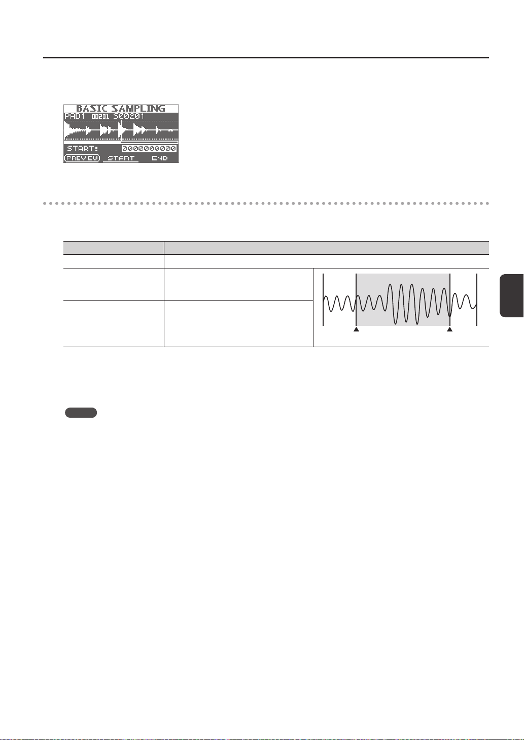
9. Use the function buttons and the [-] [+] buttons to adjust the region of the wave that will be heard.
Button Explanation
[F1] (PREVIEW) button Plays back the adjusted wave.
[F2] (START) button
Adjusts the start point (the point at which the
wave begins sounding). Use the [-] [+] buttons to
make adjustments.
This region will sound
Start point End point
[F3] (END) button
Adjusts the end point (the point at which the
wave stops sounding). Use the [-] [+] buttons to
make adjustments.
If you decide not to save the sampled wave, press the [EXIT] button to return to the previous screen.
10. Press the [ENTER] button.
The sampled sound will be saved as a wave.
MEMO
The saved wave will automatically be assigned a wave name and wave number.
You can view the waves in the WAVE LIST (p. 64).
11. Press the [ENTER] button to return to the top screen.
If you want to continue sampling, press the [SAMPLING] button.
Sampling
32
Successively Sampling to Multiple Pads (MULTI PAD)
Here’s how to sample sound from a microphone or audio device to multiple pads in succession.
Preparations for sampling
1. Connect your sampling source (microphone or audio device) (p. 12).
2. Adjust the input level of the sound from the connected device (p. 29).
3. Press the [SAMPLING] button to access the SAMPLING screen.
4. Use the cursor [
] [ ] buttons to select “MULTI,” and press the [ENTER] button.
The sampling setup screen will appear.
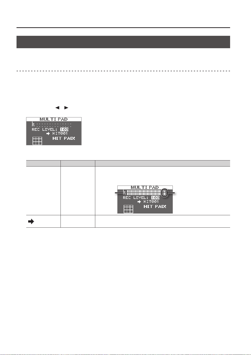
5. Use the cursor buttons and the [-] [+] buttons to make settings for sampling.
Parameter Value Explanation
REC LEVEL 0–100
Adjusts the volume at which sampling will occur.
Produce sound on the device that’s connected to the SPD-SX, and adjust the volume until it’s
as high as you can get it without causing the level overload indication to appear.
Level overload indicationLevel meter
KIT001–100
Species the kit to which the sampled waves will be assigned.
* You can only select an empty kit in which no wave has been assigned to any of the pads.
Sampling
Sampling
33
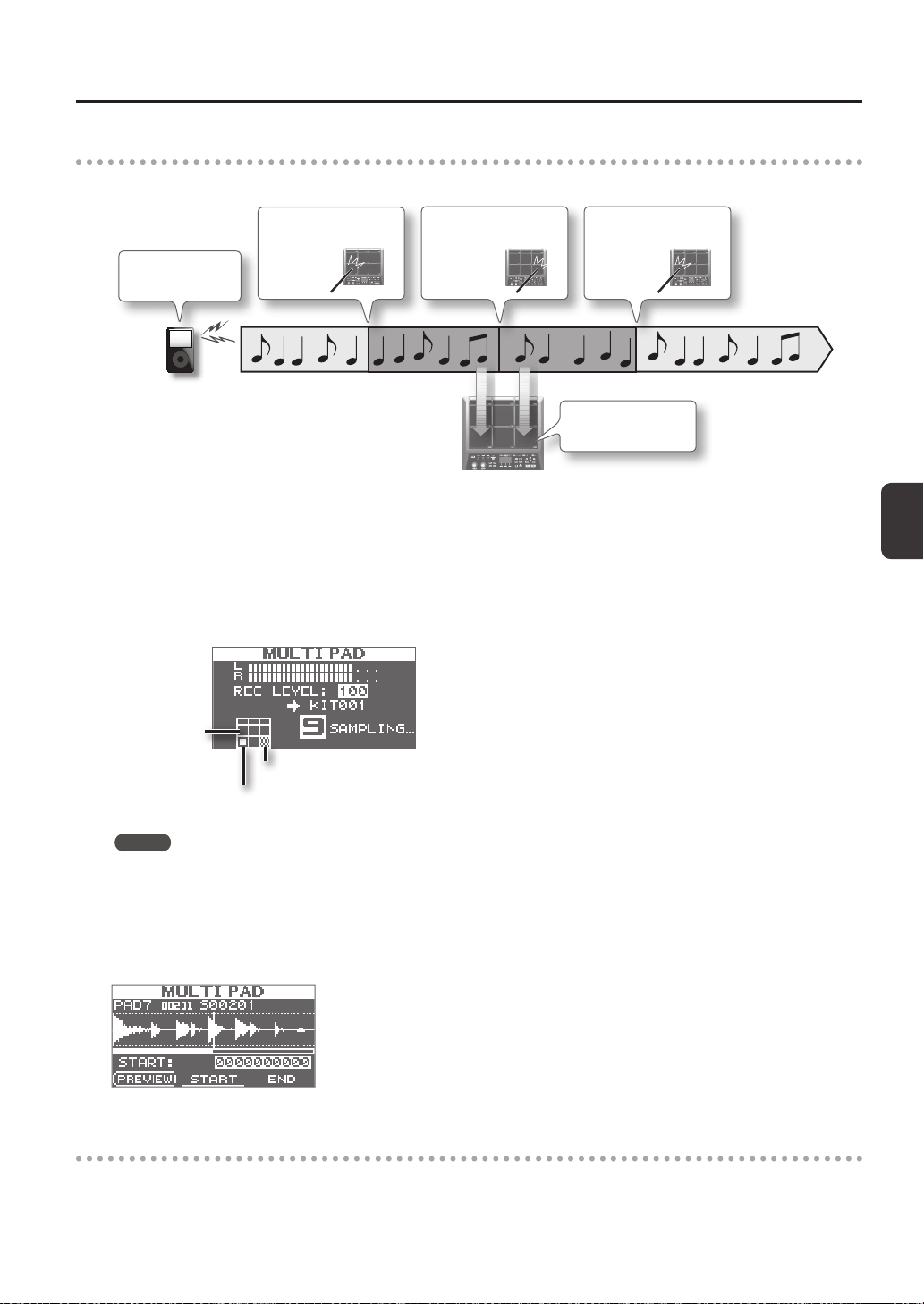
Start sampling
6. Produce sound
on your device
7. Start sampling to
pad 7
8. Start sampling to
pad 9
9. Stop sampling
Example: Sampling to pad 7 and pad 9
Pad 7
Pad 7
Pad 9
Sample to pad 7 and
pad 9
6. Produce sound on the connected device.
7. To start sampling, play the pad for which you want to sample.
8. Play the next pad for which you want to sample.
Sampling to the rst-struck pad will stop, and sampling will begin for the pad you struck next.
The screen will indicate the status of each pad.
Pad is being sampled
Pad for which sampling is complete
Unassigned pad
MEMO
Sampling to that pad will stop when you press the [ENTER] button or when you once again play the pad that’s being
sampled.
You can continue sampling by playing a pad that doesn’t have anything assigned to it yet.
9. To nish with all sampling, play one of the pads for which sampling has already been completed.
Sampling will nish, and the sampling-results screen will appear.
Saving the sampled waves
10. Save the sampled waves (p. 31).
Sampling
34
Combining Two Waves into One (MERGE)
Here’s how two waves assigned to pads of the same kit can be combined into one wave.
The combined waves will be saved in stereo.
Preparations for sampling
1. Press the [SAMPLING] button to access the SAMPLING screen.
2. Use the cursor [
] [ ] buttons to select “MERGE,” and press the [ENTER] button.
The sampling setup screen will appear.
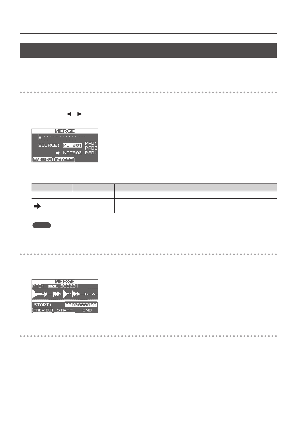
3. Use the cursor buttons and the [-] [+] buttons to make settings for sampling.
Parameter Value Explanation
SOURCE KIT001–100, PAD1–9 From a single kit, select the two waves that you want to combine.
KIT001–100, PAD1–9
Select the kit and pad to which the combined wave is to be assigned.
* You can only select an empty pad, one which has no wave assigned to it.
MEMO
You can press the [F1] (PREVIEW) button to audition the sound of the combined waves.
Start sampling
4. Press the [F2] (START) button to start sampling.
When sampling ends, the sampling-result screen will appear.
Saving the sampled waves
5. Save the sampled waves (p. 31).
Sampling
Sampling
35
Resampling with Eects (WITH FX)
Here’s how to apply a kit eect and a master eect to a sample and resample the result.
Preparations for sampling
1. Press the [SAMPLING] button to access the SAMPLING screen.
2. Use the cursor [
] [ ] buttons to select “WITH FX,” and press the [ENTER] button.
The sampling setup screen will appear.
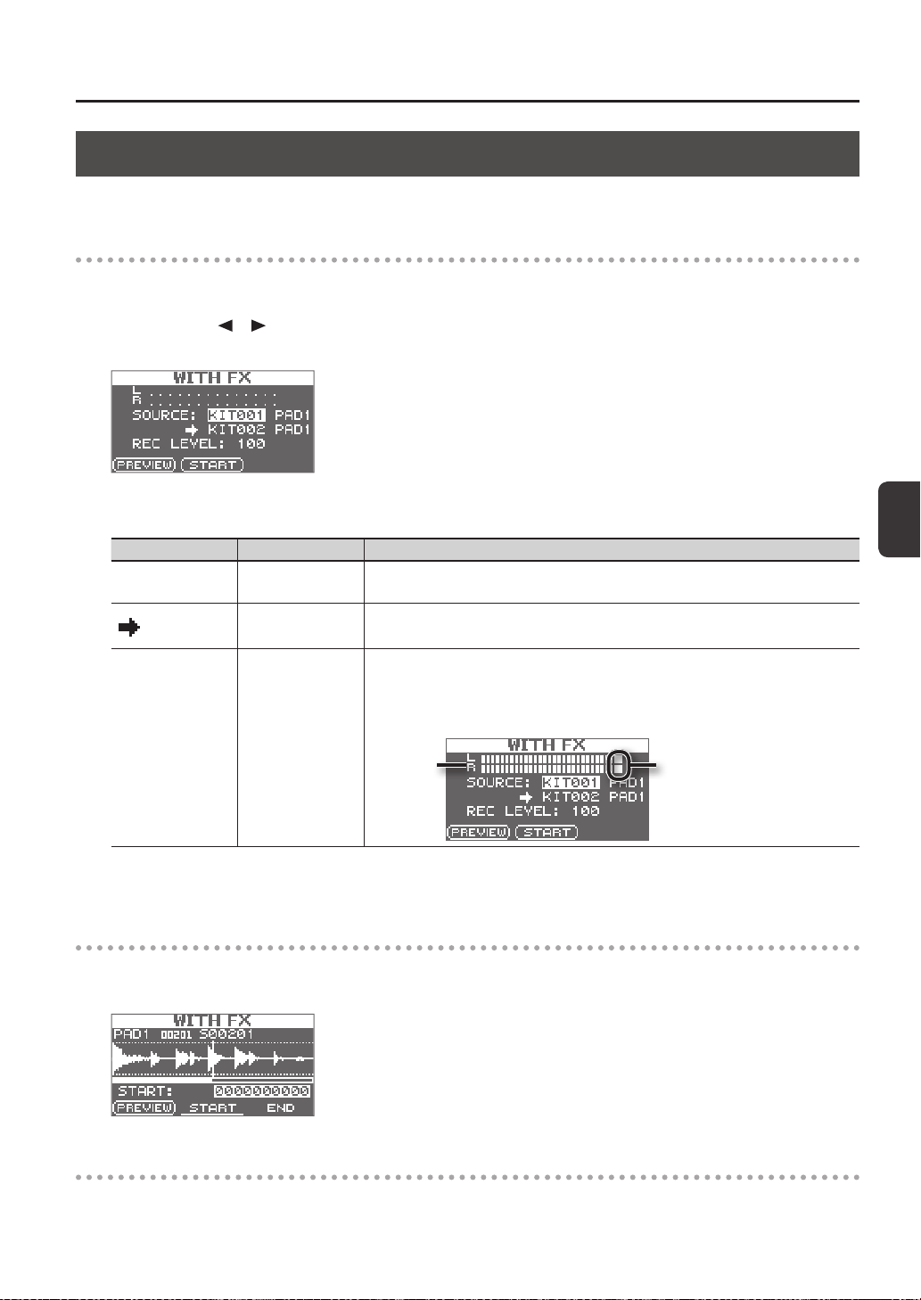
3. Use the cursor buttons and the [-] [+] buttons to make settings for sampling.
Parameter Value Explanation
SOURCE KIT001–100, PAD1–9
From the kit, select the wave to which you want to apply eects.
When sampling starts, the kit eect for the kit that is selected for SOURCE will be applied.
KIT001–100, PAD1–9
Select the kit and pad to which the wave you’ve applied eects to is to be assigned.
* You can only select an empty pad, one which has no wave assigned to it.
REC LEVEL 0–100
Adjust the sampling volume.
Play back the wave that you want to resample, and adjust the volume until it’s as high as you
can get it without causing the level overload indication to appear.
You can audition the currently selected wave by pressing the [F1] (PREVIEW) button.
Level overload indicationLevel meter
4. Turn on the master eect that you want to apply (p. 22).
Start sampling
5. Press the [F2] (START) button to start sampling.
When sampling ends, the sampling result screen will appear.
Saving the sampled waves
6. Save the sampled waves (p. 31).
Sampling
36
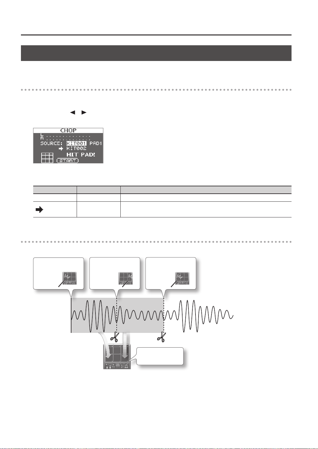
Dividing a Wave (CHOP)
Here’s how to create new waves by chopping (dividing) an existing wave.
Preparations for sampling
1. Press the [SAMPLING] button to access the SAMPLING screen.
2. Use the cursor [
] [ ] buttons to select “CHOP,” and press the [ENTER] button.
The sampling setup screen will appear.
3. Use the cursor buttons and the [-] [+] buttons to make settings for sampling.
Parameter Value Explanation
SOURCE KIT001–100, PAD1–9 Select the original wave that you want to chop.
KIT001–100
Select the kit to which the chopped waves are to be assigned.
* You can only select an empty kit in which no wave has been assigned to any of the pads.
Start sampling
Example: Chopped to pad 7 and pad 9
4. Start sampling to
pad 7
5. Start sampling to
pad 9
6. Stop sampling
Pad 7
Pad 7
Pad 9
Chopped to pad 7
and pad 9
Sampling
Sampling
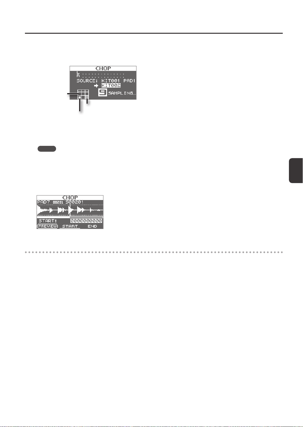
37
4. To start sampling, play the rst pad to which you want to sample.
To begin sampling from partway through a wave, press the [F2] (START) button to start playback of the wave, then play a pad
at the point where you want sampling to occur.
Pad is being sampled
Pad for which sampling is complete
Unassigned pad
5. At the moment you want to chop the sample, play the next pad to which you want to sample.
Sampling to the rst pad will stop, and sampling to the pad you struck will begin.
MEMO
Sampling to that pad will stop when you press the [ENTER] button or when you once again play the pad that’s being
sampled.
You can continue sampling by playing a pad that doesn’t have anything assigned to it yet.
6. To nish with all sampling, play one of the pads for which sampling has already been completed.
Sampling will nish, and the sampling-results screen will appear.
Saving the sampled waves
7. Save the sampled waves (p. 31).
Sampling
38
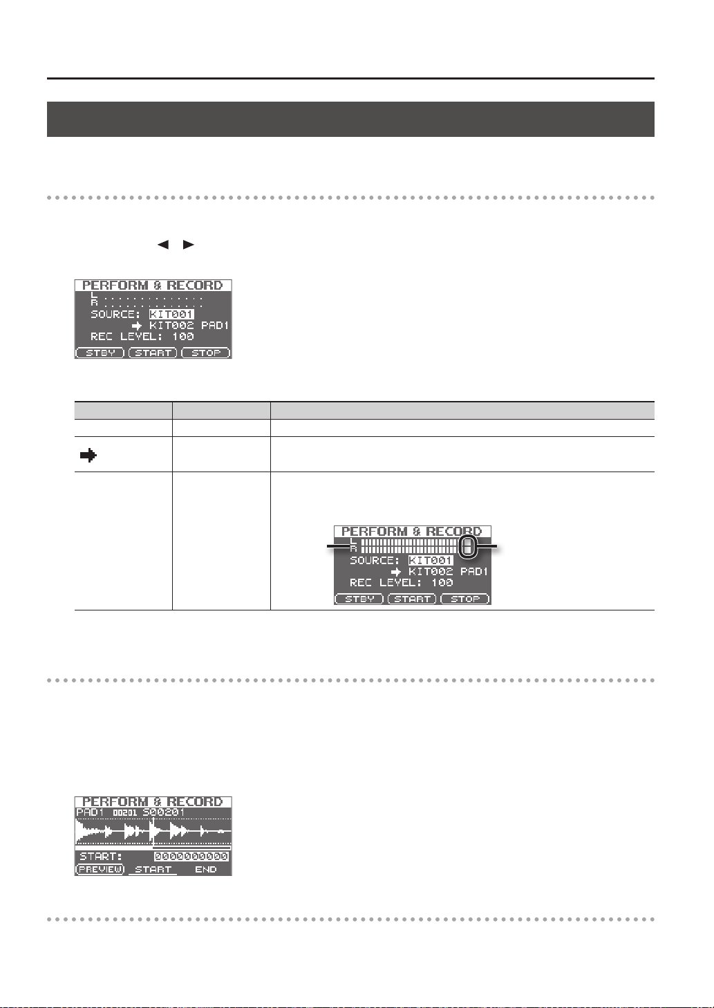
Recording the Sound of an SPD-SX Performance (PERFORM & RECORD)
The sound of your performance on the SPD-SX can be recorded and saved as a wave.
Preparations for sampling
1. Press the [SAMPLING] button to access the SAMPLING screen.
2. Use the cursor [
] [ ] buttons to select “RECORDING,” and press the [ENTER] button.
The sampling setup screen will appear.
3. Use the cursor buttons and the [-] [+] buttons to make settings for sampling.
Parameter Value Explanation
SOURCE KIT001–100 Select the kit that you want to play.
KIT001–100
Select the kit and pad to which the recorded performance is to be assigned.
* You can only select an empty pad, one which has no wave assigned to it.
REC LEVEL 0–100
Adjust the volume for sampling.
Play the pads, and adjust the volume until it’s as high as you can get it without causing the
level overload indication to appear.
Level overload indicationLevel meter
4. Press the [F1] (STBY) button.
Start sampling
5. Press the [F2] (START) button to start sampling.
Perform on the SPD-SX.
While sampling is occurring, the screen will indicate “NOW SAMPLING...”
6. Press the [F3] (STOP) button at the moment you want to stop sampling.
The sampling result screen will appear.
Saving the sampled waves
7. Save the sampled waves (p. 31).
Importing Audio Files
39
Importing Audio Files
Audio les (WAV/AIFF) can be imported from a USB ash drive or your computer into the SPD-SX as waves, and played.
Audio les that can be imported into the SPD-SX
File format Files with a le name extension of WAV or AIF/AIFF
Bit rate 16-bit
Sampling rate 44.1 kHz
Caution when importing audio les
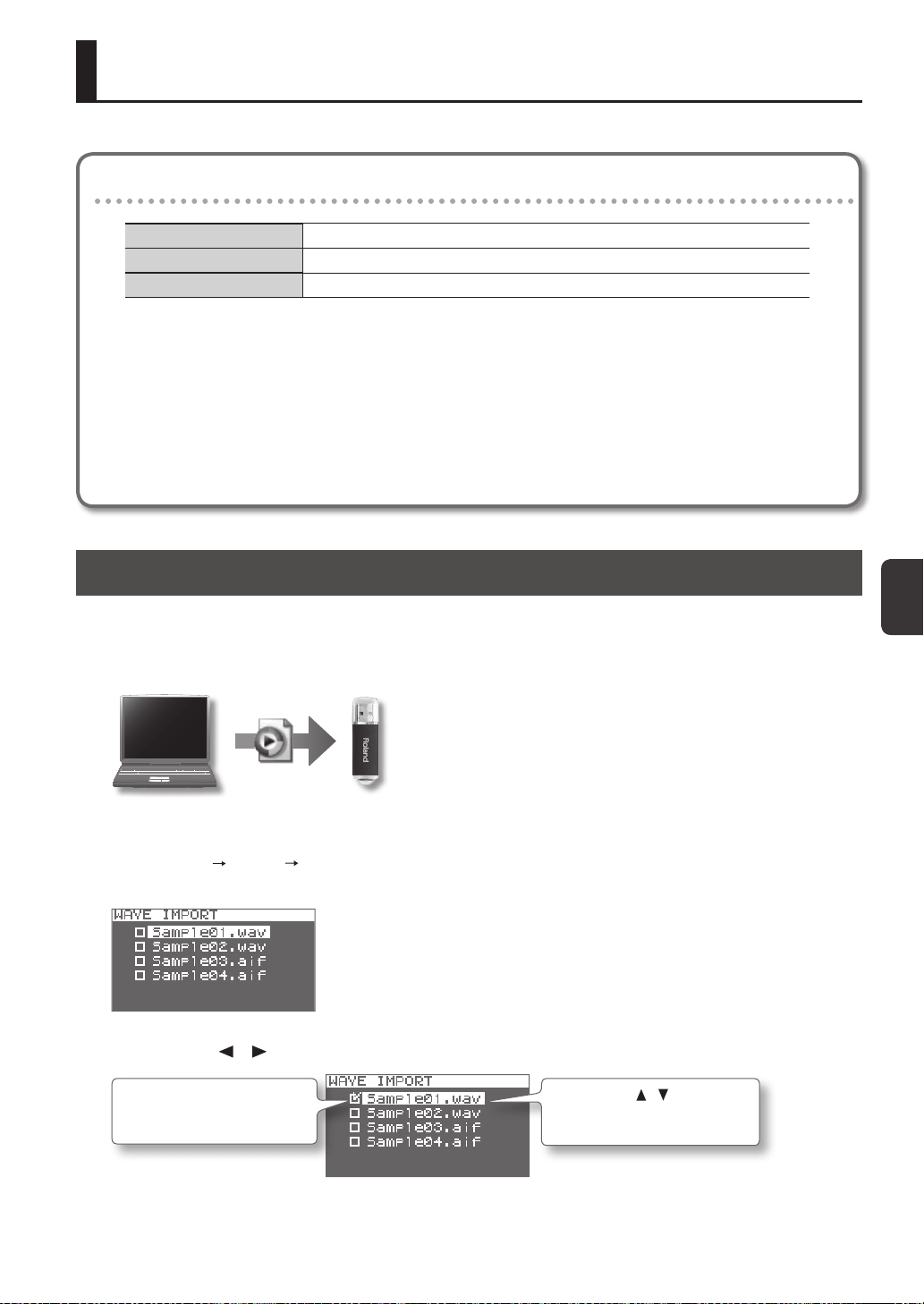
Importing Audio Files from a USB Flash Drive (WAVE IMPORT)
Here’s how to import an audio le from a USB ash drive into the SPD-SX.
* Use USB Flash Memory sold by Roland. We cannot guarantee operation if other products are used.
1. Copy the audio le you want to import into the root level (the top level) of your USB ash drive.
2. Connect your USB ash drive to the SPD-SX’s USB MEMORY connector (p. 18).
3. Choose MENU
UTILITY WAVE IMPORT.
The WAVE IMPORT screen will appear.
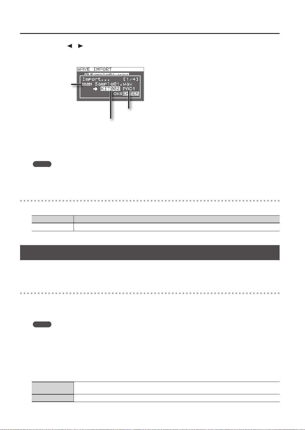
4. Use the cursor [ ] [ ] buttons and the [-] [+] buttons to select the audio le that you want to import.
Use the cursor [ ] [ ] buttons to
select the audio le that you want
to import.
Use the [-] [+] buttons to add a
check mark to the audio le that
you want to import.
5. Press the [ENTER] button.
• File names that have more than twelve characters will not appear properly.
• Loop points set in AIFF les are disabled.
• If you try to import any WAV/AIFF le in a format that is not supported by the SPD-SX, an error message of
“UNSUPPORTED FORMAT.” is displayed as that le can not be imported.
• No compressed audio les (WAV/AIFF) can be imported.
• Audio les shorter than 10 ms might not play correctly.
Importing Audio Files
40
6. Use the cursor [ ] [ ] buttons and the [-] [+] buttons to select the kit and pad to which you want to assign
the audio le.
* You’ll only be able to select an empty kit that contains no waves for any of the pads.
Pad to which the le will be assigned
Kit to which the le will be assigned
Audio le to import
7. Press the [ENTER] button.
The audio le will be imported.
If you want to import multiple audio les, repeat steps 6 and 7 to specify the assignment destination for each audio le.
MEMO
Wave numbers will automatically be assigned to the imported waves.
You can view these waves in the WAVE LIST (p. 64).
WAVE IMPORT screen quick menu
In the WAVE IMPORT screen, pressing the [QUICK] button will display the following quick menu.
Menu Explanation
REMAINING MEM Indicates the remaining amount of internal memory and the remaining amount of time for sampling.
Importing Audio Files from Your Computer
By using “SPD-SX Wave Manager,” provided on the included CD-ROM, audio les from your computer can be imported into the
SPD-SX as waves.
SPD-SX Wave Manager
• Audio les (WAV/AIFF) saved on your computer can be imported as SPD-SX waves.
• WAV/AIFF les from your computer can be assigned directly to a kit.
• You can edit the name of the kit and wave.
MEMO
For details on how to use the software, refer to the Help documentation included with SPD-SX Wave Manager.
1. Install SPD-SX Wave Manager.
For details on how to install SPD-SX Wave Manager, refer to “ReadmeEN.txt” on the included CD-ROM.
2. Connect the SPD-SX to your computer (p. 18).
3. Start up SPD-SX Wave Manager.
Windows
Click [Start], then move the mouse cursor to [All Programs] and then [SPD-SX Wave Manager], and click [SPD-SX Wave
Manager].
Mac OS X In [Applications], double-click [SPD-SX Wave Manager].
Importing Audio Files
Importing Audio Files
41
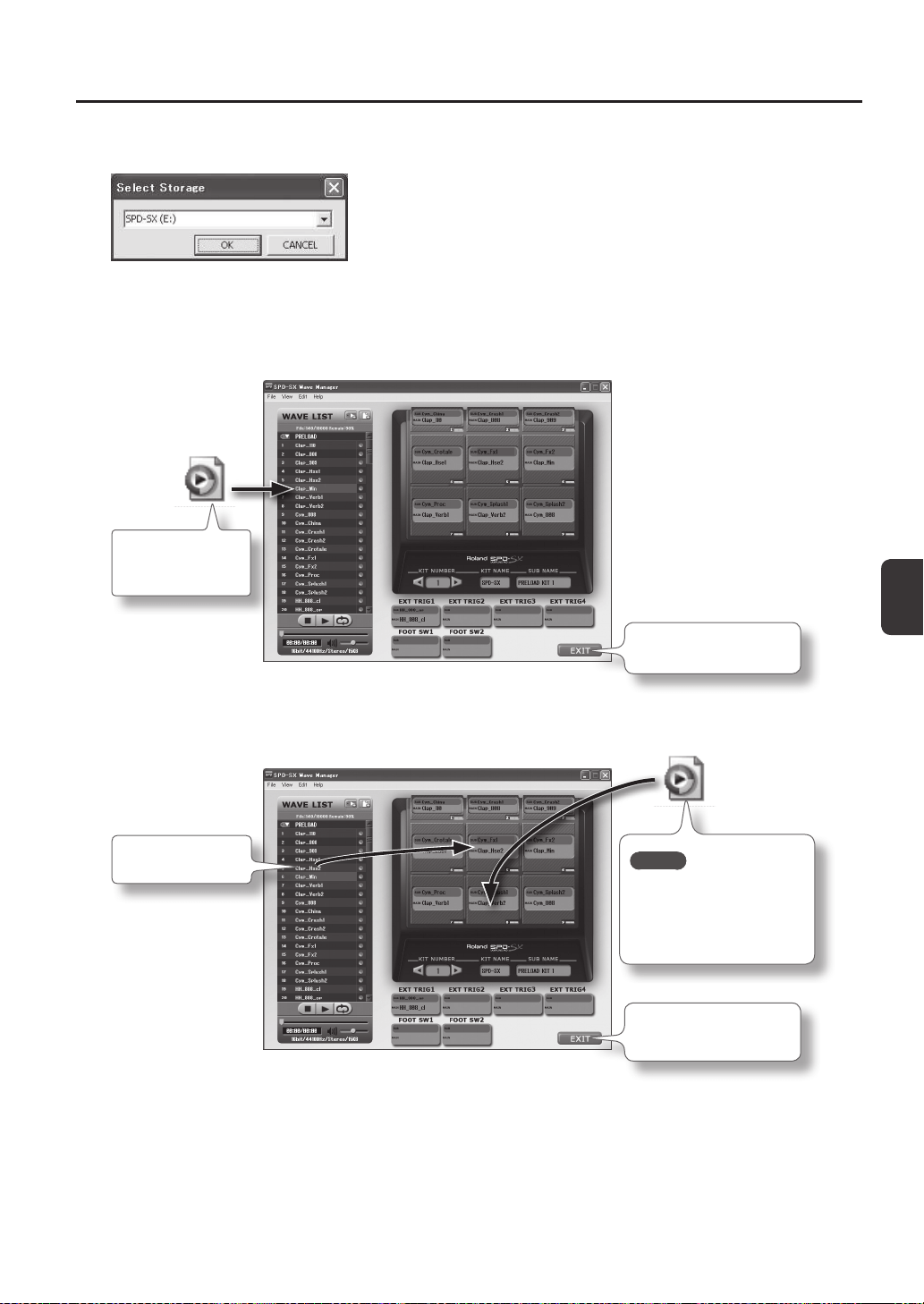
4. Select the SPD-SX drive.
The “Select Storage” dialog box will appear.
Using the drop-down list in the “Select Storage” dialog box, select the [SPD-SX] drive, and click [OK].
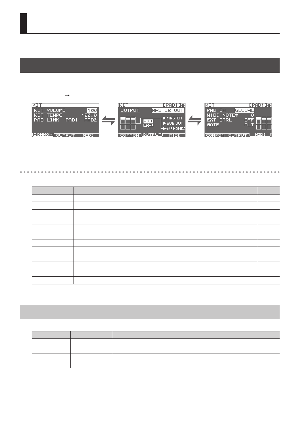
5. Import audio les into the SPD-SX.
Importing waves into the SPD-SX
Drag and drop a
WAV le or AIFF le
into the wave list.
Click this to exit SPD-SX
Wave Manager.
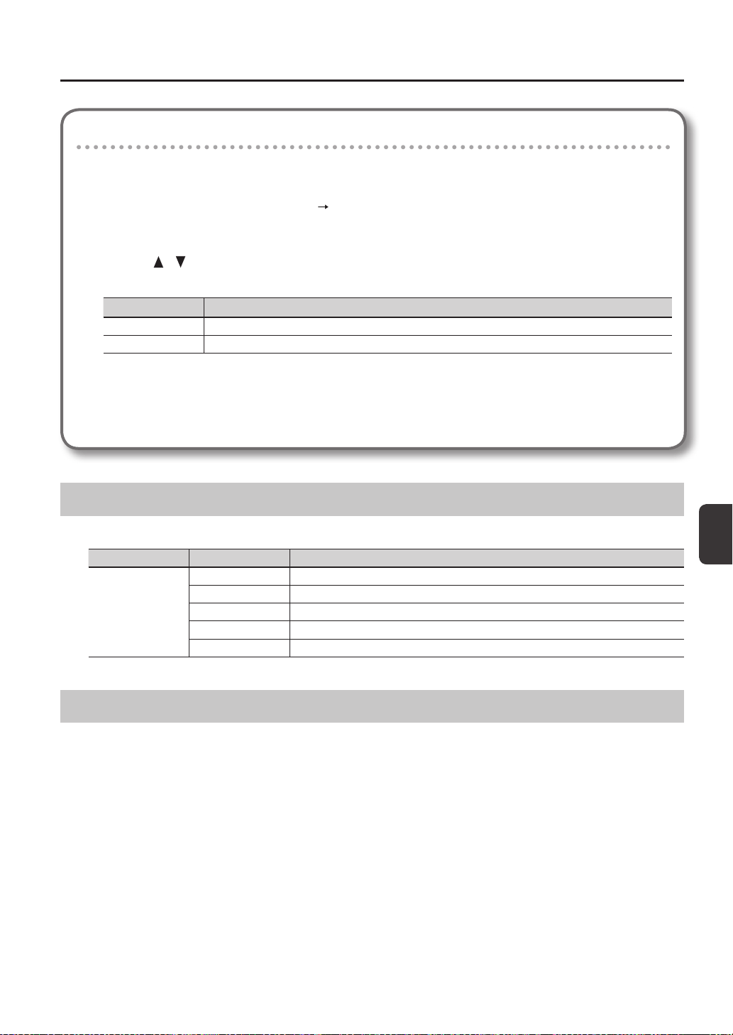
Assigning a wave to a pad
Drag and drop a
wave onto a pad.
MEMO
You can also drag and drop
WAV les or AIFF les onto
a pad. This imports and
assigns the wave in a single
step.
Click this to exit SPD-SX
Wave Manager.
42
Customizing a Kit
Here’s how to customize a kit. For each pad, you can assign the desired wave and specify how it will sound.
Settings for the Entire Kit (KIT)
Here you can make overall settings for the entire kit, such as volume and output. For the procedure, refer to “Basic Editing
Procedure” (p. 16).
1. Choose MENU
KIT.
2. Edit the parameters.
KIT screen quick menu
In the KIT screen, pressing the [QUICK] button will display the following quick menu.
Menu Explanation Page
KIT NAME Edits the kit name. p. 47
KIT COPY Copies a kit. p. 48
KIT PASTE Pastes a kit. p. 48
KIT INIT Initializes a kit. p. 49
MULTI VIEW Lists the settings of the selected parameter for all pads. -
PAD LOCK Turn PAD LOCK on/o. p. 63
SET ALL PAD Copies a parameter setting to all pads. p. 47
PAD COPY Copies a pad. p. 48
PAD PASTE Pastes a pad. p. 48
PAD EXCHANGE Exchanges pads. p. 49
PAD INIT Initializes a pad. p. 49
TEMPO MATCH Sets the kit tempo as a tempo value calculated from the length of the wave. p. 43
* For some pages of the KIT screen, some of the quick menu items are not shown.
Adjusting the Kit Volume and Tempo (COMMON)
Here you can adjust the overall volume and tempo of the entire kit.
Parameter Value Explanation
KIT VOLUME 0–100 Adjusts the volume of the entire kit.
KIT TEMPO 20.0–260.0 Species the tempo of the kit.
PAD LINK
OFF, PAD1–PAD9,
TRIG1–4, FS1, FS2
Sounds two pads simultaneously.
Playing either of the specied pads will sound both pads simultaneously.
Customizing a Kit
Customizing a Kit
43
Specifying the kit’s tempo according to the length of a wave
This operation calculates the tempo based on the length of a wave, and assigns it as the tempo of the kit (KIT TEMPO).
This is convenient when you want to set the kit tempo based on a wave.
1. In the KIT screen, choose QUICK MENU
TEMPO MATCH.
2. Play the pad to which is assigned the wave whose length you want to calculate.
3. Use the [
] [ ] buttons and the [-] [+] buttons to specify the time signature (BEAT) and number of
measures (MEASURE) of the wave.
Parameter Value
BEAT 1/4–16/4, 1/8–16/8
MEASURE 1–999
When you specify the BEAT and MEASURE, the calculated tempo will be displayed.
4. Press the [ENTER] button.
The calculated tempo will be specied as the KIT TEMPO setting.
Output Assignments (OUTPUT)
Here you can specify the jack(s) from which the sound of each pad will be output.
Parameter Value Explanation
OUTPUT
MASTER OUT Output from the MASTER OUT jacks and the PHONES jack.
KIT FX1 Apply a kit eect (FX1) and output from the MASTER OUT jacks and the PHONES jack.
KIT FX2 Apply a kit eect (FX2) and output from the MASTER OUT jacks and the PHONES jack.
SUB OUT Output from the SUB OUT jacks and the PHONES jack.
PHONES ONLY Output from the PHONES jack.
MIDI Settings (MIDI)
Here you can make MIDI-related settings for each pad. Refer to “MIDI Settings for Each Pad (MIDI)” (p. 67).
Customizing a Kit
44
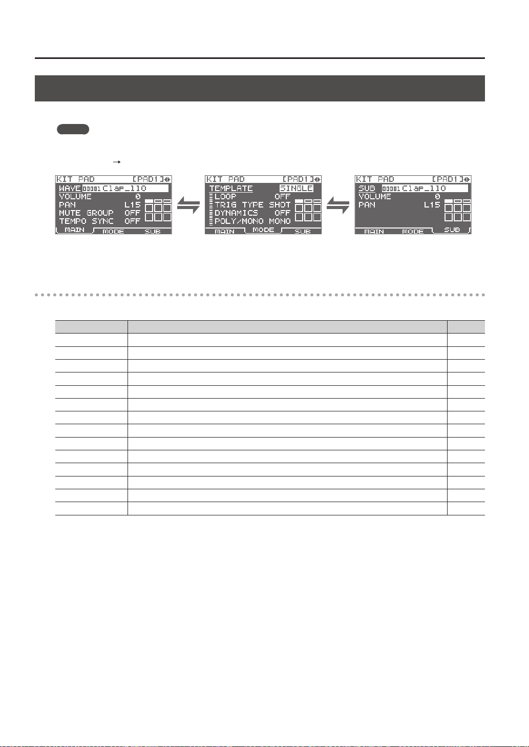
Specifying How a Wave Will Sound (KIT PAD)
For each pad, you can specify how the wave will be sounded. The procedure is described in “Basic Editing Procedure” (p. 16).
MEMO
You can assign two waves (wave and sub wave) to a pad, and sound them simultaneously.
1. Choose MENU
KIT PAD.
2. Edit the parameters.
KIT PAD screen quick menu
In the KIT PAD screen, pressing the [QUICK] button will display the following quick menu.
Menu Explanation Page
MULTI VIEW Lists the settings of the selected parameter for all pads. -
PAD LOCK Turns PAD LOCK on/o. p. 63
SET ALL PAD Copies a parameter setting to all pads. p. 47
PAD COPY Copies a pad. p. 48
PAD PASTE Pastes a pad. p. 48
PAD EXCHANGE Exchanges pads. p. 49
PAD INIT Initializes a pad. p. 49
WAVE LIST Jumps to the WAVE LIST screen. p. 64
WAVE NAME Renames a wave. p. 47
WAVE START/END Assigns the wave’s start point and end point. p. 50
WAVE NORMALIZE Adjusts a wave’s volume. p. 50
WAVE PITCH Adjusts a wave’s pitch. p. 50
WAVE REVERSE Creates a reverse-playback wave. p. 51
WAVE TRUNCATE Deletes the unwanted portion of a wave. p. 51
Customizing a Kit
Customizing a Kit
45
Selecting the Wave Played by a Pad (MAIN)
Here you can make basic settings such as selecting the wave played by a pad and specifying its volume.
Parameter Value Explanation
WAVE 00001–10000
Selects the wave played by the pad.
MEMO
• The SPD-SX contains preload waves.
• The preload waves are also stored on the supplied CD-ROM. If you want to make use of
the preload waves that came with the unit when it left the factory, load waves from a USB
ash drive or your personal computer (p. 39).
• Waves can also be selected from the WAVE LIST of the quick menu.
• By holding down the [PAD CHECK] button and using the [-] [+] buttons you can select the
wave in steps of 10.
VOLUME 0–100
Adjusts the volume of the pad.
MEMO
You can also set the VOLUME from the top screen (p. 26).
PAN L15–CENTER–R15 Adjusts the stereo position (left/right balance) of the sound.
MUTE GROUP OFF, 1–9
Pads for which the same number is specied here will belong to the same mute group. A
newly played pad will silence any previously sounding pad that belongs to the same mute
group; only the most recently played pad in the mute group will be heard.
Specify the same mute group for pads that should not be heard together.
* The pad indicator of all pads in the same mute group will light.
TEMPO SYNC OFF, ON
If this is “ON,” the wave’s playback speed will change according to the performance tempo.
* Drastic changes in playback speed may aect the quality of the sound.
Specifying How the Wave is Sounded (MODE)
Here you can specify how the wave will be sounded.
Parameter Value Explanation
TEMPLATE
Species how the wave will be sounded.
* If you set TEMPLATE, the MODE parameters will be set to suitable values.
SINGLE Choose this for sounds used to play single notes, such as percussion sounds.
PHRASE Choose this for phrases that have a tempo.
LOOP Choose this when you want the wave to sound repeatedly.
LOOP OFF, ON, x2, x4, x8
Species the number of times that the wave will be repeated.
If this is “ON,” the wave will continue repeating.
TRIG TYPE
Species how the wave will play when you play the pad.
SHOT The wave will play each time you play the pad.
ALT The wave will alternately play or stop each time you play the pad.
DYNAMICS OFF, ON
Set it to “ON” to change the volume according to playing velocity. When it is set to “OFF,” the
sound is produced at a constant volume.
POLY/MONO
Species whether the wave will play polyphonically or monophonically.
MONO Repeated plays will silence the previous sound.
POLY Repeated plays will be layered on the previous sound.
Customizing a Kit
46
Playing the Second Wave (SUB)
Here you can make settings for the second wave (sub wave).
Make these setting when you want two waves to sound simultaneously from a single pad.
Parameter Value Explanation
SUB 00001–10000
Selects the wave that will be sounded by the pad.
MEMO
• The SPD-SX contains preload waves.
• The preload waves are also stored on the supplied CD-ROM. If you want to make use of
the preload waves that came with the unit when it left the factory, load waves from a USB
ash drive or your personal computer (p. 39).
• By holding down the [PAD CHECK] button and using the [-] [+] buttons you can select the
wave in steps of 10.
VOLUME 0–100 Adjusts the volume of the sub wave.
PAN L15–CENTER–R15 Adjusts the stereo position (left/right balance) of the sound.
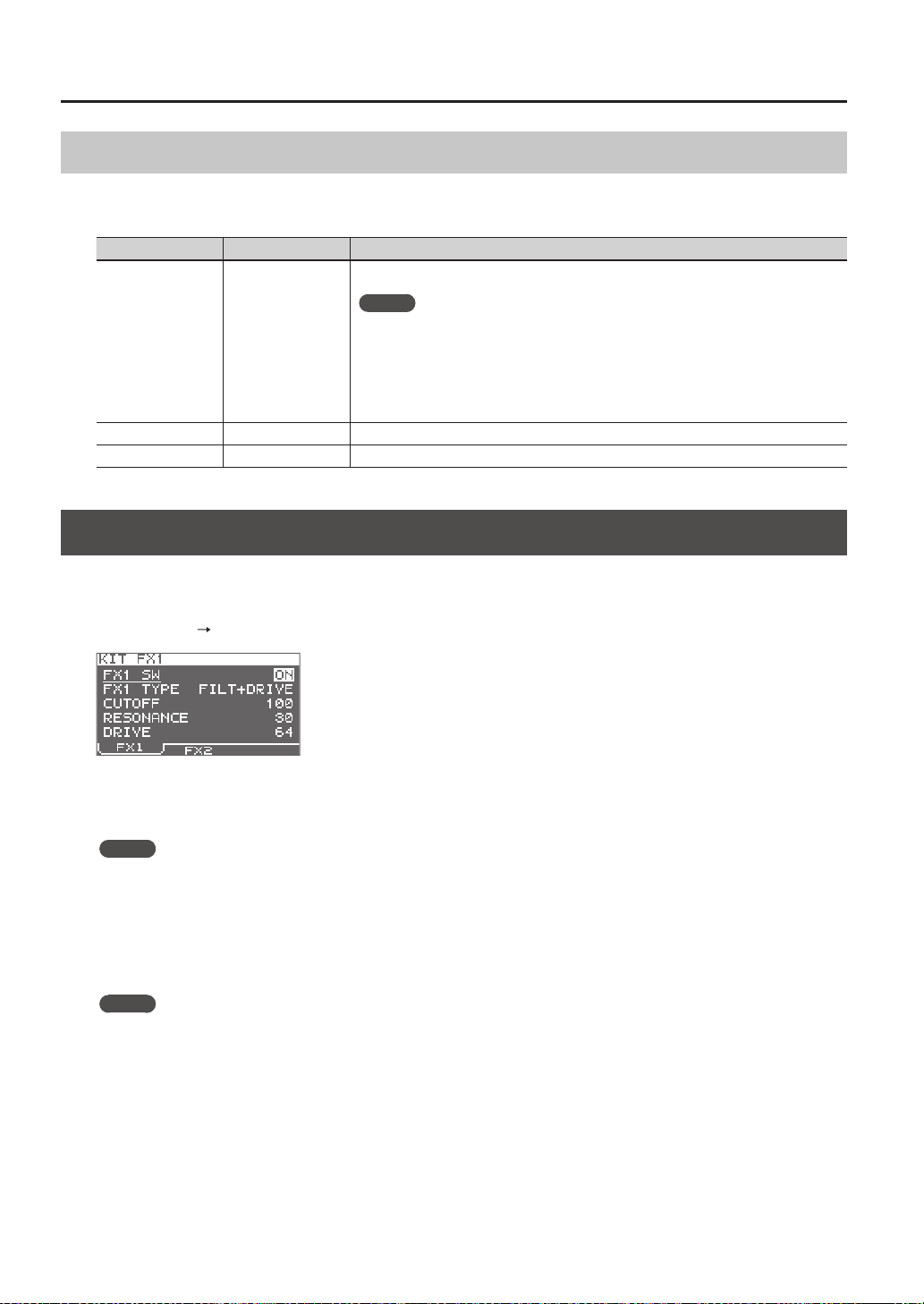
Applying a Kit Eect (KIT FX)
The kit eects provide a choice of 20 dierent eect types.
Two kit eects (FX1 and FX2) can be applied to each kit.
1. Choose MENU
KIT FX.
2. Turn the kit eect on.
Turn FX SW “ON” if you want to turn FX1 on, and turn FX2 SW “ON” if you want to turn FX2 on.
MEMO
You can also turn the kit eects on/o from the top screen (p. 23).
3. Edit the parameters.
When you switch the eect type (FX1 TYPE or FX2 TYPE), the editable parameters for each eect type will be shown.
For details on the eect types and their parameters, refer to the Eect Guide.
For the procedure, refer to “Basic Editing Procedure” (p. 16).
MEMO
The Eects Guide can be downloaded from the Roland website.
Visit the following URL, choose “owner’s manuals,” and search for the model name “SPD-SX.”
http://www.roland.com/support/en/
Customizing a Kit
Customizing a Kit
47
Copying Parameter Settings to All Pads (SET ALL PAD)
Here’s how to copy the value of the selected parameter to all pads of the same kit.
1. In any of the KIT PAD screens, move the cursor to the parameter that you want to copy.
2. Choose QUICK MENU
SET ALL PAD.
3. Press the [ENTER] button.
A conrmation message will appear.
If you decide to cancel the operation, press the [EXIT] button.
4. Press the [ENTER] button once again.
The value will be copied to all pads of the same kit.
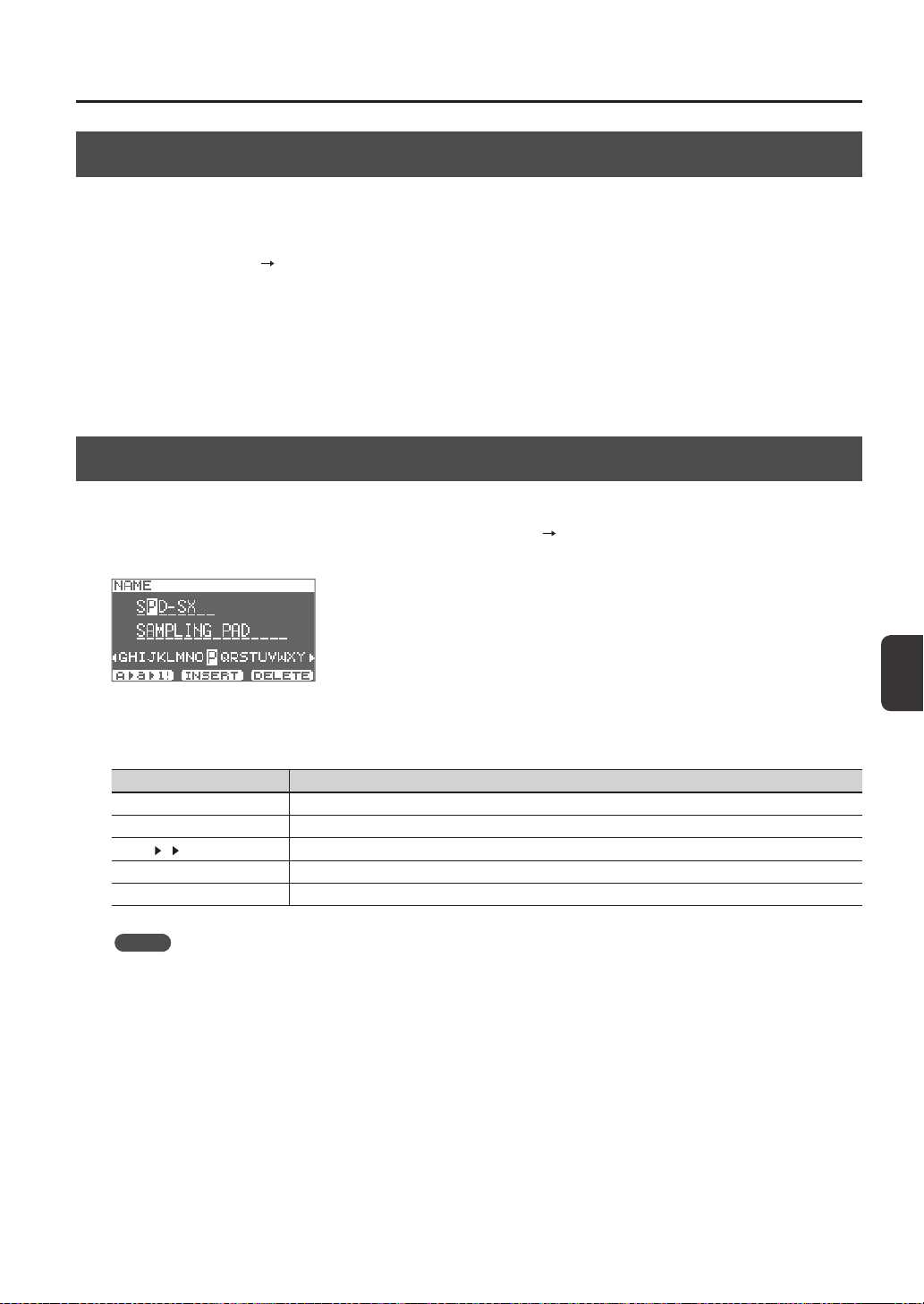
Assigning a Name (NAME)
Here’s how to assign a name to a kit or wave.
1. In the KIT screen (or the top screen, etc.), choose QUICK MENU
KIT NAME.
The NAME screen will appear.
* The NAME screen will also appear for other quick Menu items (WAVE NAME (p. 64), CHAIN NAME (p. 56)).
2. Enter the name.
Button Explanation
[-] [+] buttons Change characters.
Cursor buttons Move the cursor to the character you want to change.
[F1] (A
a 1!) button
Switches the type of character at the cursor location between uppercase, lowercase, and numerals/symbols.
[F2] (INSERT) button Inserts a space at the cursor location, moving subsequent characters one space to the right.
[F3] (DELETE) button Deletes the character at the cursor location, moving subsequent characters one space to the left.
MEMO
A kit can be given a sub name (SUB NAME) in addition to the kit name.
The sub name can be used as a reminder about the kit, such as date of creation, the name of the song you are using it in,
etc.
If DISP MODE (p. 59) is set to “SUB NAME,” the sub name will be shown in the top screen.
3. Press the [ENTER] button to nalize the name.

Customizing a Kit
48
Copying Kits or Pads
Here’s how to copy the settings of a kit or pad.
Copying a Kit
Here’s how to copy the settings of the currently selected kit.
1. Select the copy-source kit (p. 21).
2. In the KIT screen (or the top screen, etc.), choose QUICK MENU
KIT COPY.
3. Press the [ENTER] button.
The kit will be copied.
4. Select the copy-destination kit (p. 21).
5. In the KIT screen (or the top screen, etc.), choose QUICK MENU
KIT PASTE.
6. Press the [ENTER] button.
A conrmation message will appear.
If you decide not to execute, press the [EXIT] button.
7. Press the [ENTER] button once again.
The kit will be pasted.
Copying a Pad
This operation copies the settings of the last-struck pad, allowing you to paste them to a dierent pad. You can also paste to a
dierent kit.
1. In the KIT screen (or the top screen, etc.), choose QUICK MENU
PAD COPY.
The indicator of the copy-source pad will blink. You can also change this by playing a pad.
2. Press the [ENTER] button.
The pad will be copied.
3. Play a pad to select the copy-destination pad.
If you want to paste to a dierent kit, select the paste-destination kit.
4. In the KIT screen (or the top screen, etc), choose QUICK MENU
PAD PASTE.
The indicator of the copy-destination pad will blink. You can also change this by playing a pad.
5. Press the [ENTER] button.
The pad will be pasted.

Customizing a Kit
Customizing a Kit
49
Exchanging Pads (PAD EXCHANGE)
This operation exchanges the settings of two pads. You can also exchange pads between dierent kits.
1. In the KIT screen (or the top screen, etc.), choose QUICK MENU
PAD EXCHANGE.
The PAD EXCHANGE screen will appear.
2. Play the rst pad.
The screen will indicate the selected pad, and the pad’s indicator will blink.
If you want to exchange pads with a dierent kit, select the other kit.
3. Play the other pad that you want to exchange.
The pads will be exchanged.
Initializing a Kit or Pad
Here’s how to initialize the settings of a kit or pad.
Initializing a Kit (KIT INIT)
This will initialize the settings of the currently selected kit (all parameters in KIT, KIT PAD, and KIT EFFECT).
* The kit settings will be lost when you execute KIT INIT. If you want to keep the settings, save them to a USB ash drive
before you continue (p. 66).
1. Select the kit that you want to initialize (p. 21).
2. In the KIT screen (or the FX screen), choose QUICK MENU
KIT INIT.
3. Press the [ENTER] button.
A conrmation message will appear.
If you decide to cancel the operation, press the [EXIT] button.
4. Press the [ENTER] button once again.
The kit will be initialized.
Initializing a Pad (PAD INIT)
This will initialize the settings of the pad (all parameters in KIT PAD).
* The pad settings will be lost when you execute PAD INIT. If you want to keep the settings, save them to a USB ash drive
before you continue (p. 66).
1. In the KIT screen (or the KIT PAD screen), choose QUICK MENU
KIT PAD INIT.
2. Play the pad that you want to initialize.
3. Press the [ENTER] button.
A conrmation message will appear.
If you decide to cancel the operation, press the [EXIT] button.
4. Press the [ENTER] button once again.
The pad will be initialized.
50
Editing a Wave
You can edit a wave in various ways, such as normalizing
its volume or deleting unwanted portions.
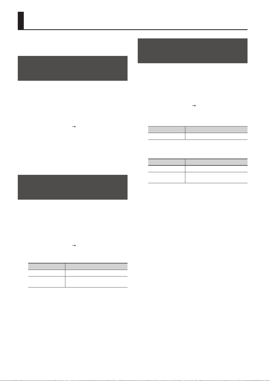
Specifying a Wave’s Start and
End (WAVE START/END)
If a sampled wave has unwanted sound or blank space at
its beginning or end, you can specify the start and end of
the portion that will actually be sounded, thus omitting
the unwanted regions.
1. In the KIT PAD screen, select the wave that you
want to edit (p. 44).
2. Choose QUICK MENU
WAVE START/END.
3. Adjust the region of the wave that you want to
be heard (p. 31).
4. Press the [ENTER] button.
The setting will be saved, and you’ll be returned to the
KIT PAD screen.
Normalizing a Wave’s Volume
(WAVE NORMALIZE)
This operation boosts the volume of a wave as far as
possible without causing it to distort. You may wish to
use this if the volume of a sampled wave is not loud
enough.
1. In the KIT PAD screen, select the wave that you
want to edit (p. 44).
2. Choose QUICK MENU
WAVE NORMALIZE.
3. Select the save-destination wave.
Button Explanation
[ENTER] button Save as a new wave.
[F3] (OVER WRITE)
button
Save by overwriting the original wave.
A conrmation message will appear.
If you decide to cancel the operation, press the [EXIT]
button.
4. Press the [ENTER] button.
The WAVE NORMALIZE operation will be carried out.
Adjusting the Pitch of a Wave
(WAVE PITCH)
Here’s how to adjust the pitch of a wave.
By adjusting the pitch, you can obtain an eect that
sounds as if the playback speed has been changed.
1. In the KIT PAD screen, select the wave that you
want to edit (p. 44).
2. Choose QUICK MENU
WAVE PITCH.
3. Use the [-] [+] buttons to adjust the pitch.
Parameter Value
PITCH -1200–+1200cent
4. Select the save-destination wave.
Button Explanation
[ENTER] button Save as a new wave.
[F3] (OVER WRITE)
button
Save by overwriting the original wave.
A conrmation message will appear.
If you decide to cancel the operation, press the [EXIT]
button.
5. Press the [ENTER] button.
The WAVE PITCH operation will be carried out.
Editing a Wave
Editing a Wave
51
Creating a Wave That Plays in
Reverse (WAVE REVERSE)
This operation creates a wave that plays in reverse from
an existing wave.
1. In the KIT PAD screen, select the wave that you
want to edit (p. 44).
2. Choose QUICK MENU
WAVE REVERSE.
3. Select the save-destination wave.
Button Explanation
[ENTER] button Save as a new wave.
[F3] (OVER WRITE)
button
Save by overwriting the original wave.
A conrmation message will appear.
If you decide to cancel the operation, press the [EXIT]
button.
4. Press the [ENTER] button.
The WAVE REVERSE operation will be carried out.
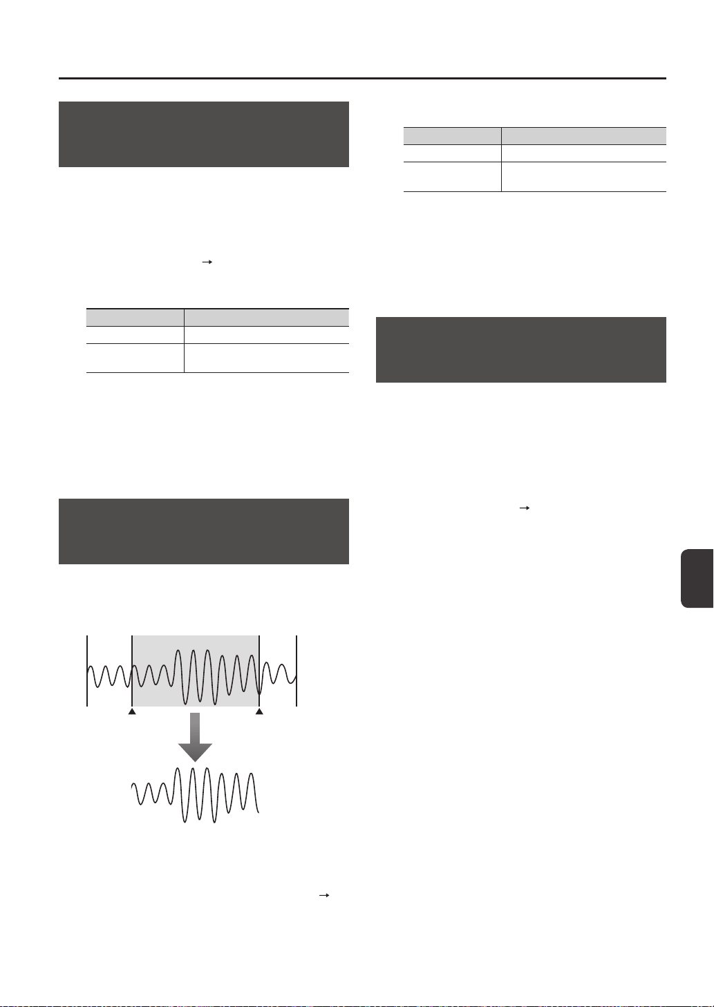
Deleting Unwanted Regions of
a Wave (WAVE TRUNCATE)
By specifying the region of a wave that you want to
be sounded (start point and end point), then erasing
portions that are no longer needed, you can conserve
memory.
This region will sound
Start point End point
WAVE TRUNCATE
1. Specify the start point and end point of the wave
that you want to edit (p. 50).
2. In the KIT PAD screen, choose QUICK MENU
WAVE TRUNCATE.
3. Select the save-destination wave.
Button Explanation
[ENTER] button Save as a new wave.
[F3] (OVER WRITE)
button
Save by overwriting the original wave.
A conrmation message will appear.
If you decide to cancel the operation, press the [EXIT]
button.
4. Press the [ENTER] button.
The WAVE TRUNCATE operation will be carried out.
Assigning a Category to a Wave
(WAVE CATEGORY)
Here’s how you can assign a category to a wave.
Once you’ve assigned a category, you’ll be able to view
the waves sorted by category in the WAVE LIST screen
(p. 64).
1. In the WAVE LIST screen, select the wave that you
want to assign (p. 64).
2. Choose QUICK MENU
WAVE CATEGORY.
3. Use the cursor [-] [+] buttons to select the
desired category, and press the [ENTER] button.
The category will be assigned to the wave, and you’ll be
returned to the WAVE LIST screen.
Editing a Wave
52
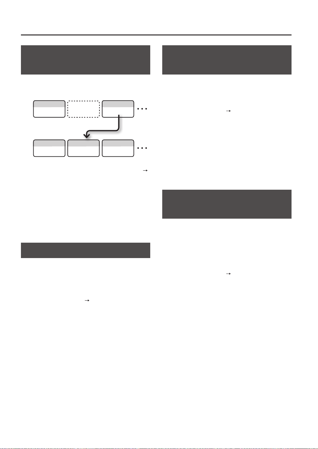
Organizing the Waves
(RENUMBER)
If there are wave numbers that do not contain a wave,
executing this operation will reassign the subsequent
wave numbers so that they are consecutive.
WAVE01001
WAVE01001 WAVE01002
WAVE01003
WAVE01003
RENUMBER
my wave3
Empty wave
my wave1
my wave1
my wave3
my wave4
1. In the WAVE LIST screen, choose QUICK MENU
RENUMBER (p. 64).
2. Press the [ENTER] button.
A conrmation message will appear.
If you decide to cancel the operation, press the [EXIT]
button.
3. Press the [ENTER] button.
The RENUMBER operation will be carried out.
Copying a Wave (WAVE COPY)
Here’s how to copy one wave in order to create a new
wave.
1. In the WAVE LIST screen, select the wave that you
want to copy (p. 64).
2. Choose QUICK MENU
WAVE COPY.
3. Press the [ENTER] button.
The wave will be copied.
Deleting a Wave
(WAVE DELETE)
Here’s how to delete a wave.
1. In the WAVE LIST screen, select the wave that you
want to delete (p. 64).
2. Choose QUICK MENU
WAVE DELETE.
3. Use the cursor buttons to select the wave that
you want to delete, and press the [ENTER]
button.
A conrmation message will appear.
If you decide to cancel the operation, press the [EXIT]
button.
4. Press the [ENTER] button.
The wave will be deleted.
Saving a Wave to USB Memory
(WAVE EXPORT)
Here’s how to save a wave to a USB ash drive.
1. Connect your USB ash drive to the USB
MEMORY connector (p. 18).
2. In the WAVE LIST screen, select the wave that you
want to save (p. 64).
3. Choose QUICK MENU
WAVE EXPORT.
4. Press the [ENTER] button.
The wave will be saved to a USB ash drive.
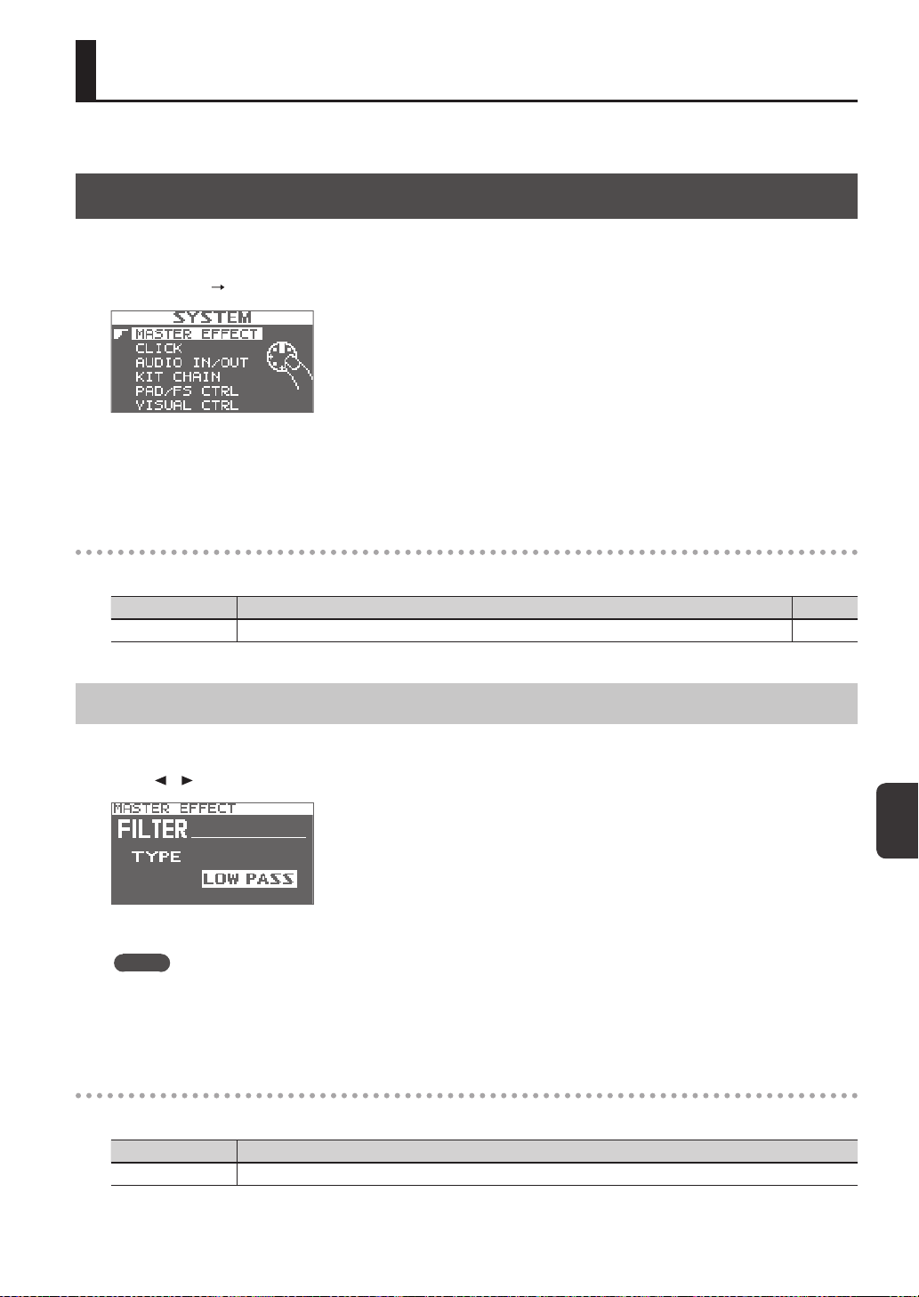
Overall Settings for the SPD-SX
53
Overall Settings for the SPD-SX
These settings apply to the entire SPD-SX.
Sound and Performance-related Settings (SYSTEM)
These are sound and performance-related settings that apply to the entire SPD-SX. For details, refer to “Basic Editing
Procedure” (p. 16).
1. Choose MENU
SYSTEM.
2. Choose the item that you want to edit.
3. Edit the parameter.
SYSTEM screen quick menu
In the SYSTEM screen, pressing the [QUICK] button will display the following quick menu.
Menu Explanation Page
SYSTEM INIT Initializes the settings of the SYSTEM parameters. p. 58
Master Eect Settings (MASTER EFFECT)
Here you can select the master eect types.
Press one of the master eect buttons to select the master eect for which you want to make settings. You can also use the
cursor [
] [ ] buttons to select a master eect.
For details on the master eect parameters, refer to the Eect Guide.
MEMO
PDF les of the Eect Guide can be obtained from the Roland website.
Visit the following URL, choose “owner’s manuals,” and search for the model name “SPD-SX.”
http://www.roland.com/support/en/
MASTER EFFECT screen quick menu
In the MASTER EFFECT screen, pressing the [QUICK] button will display the following quick menu.
Menu Explanation
MSTR FX EDIT For setting the master eect parameters.
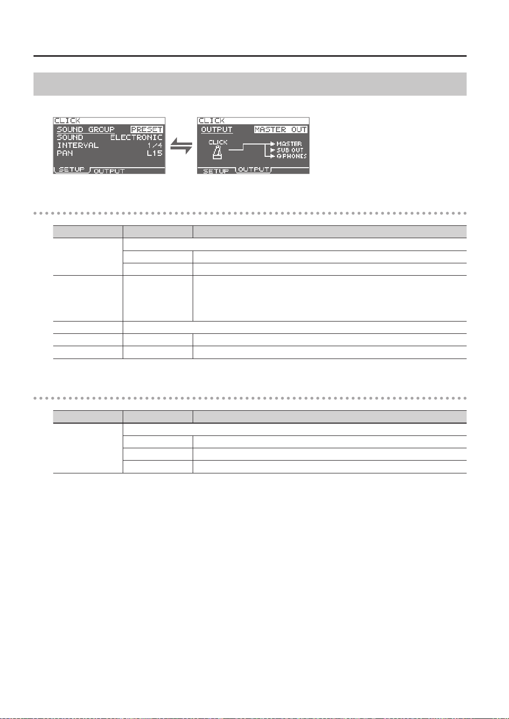
Overall Settings for the SPD-SX
54
Click Sound Settings (CLICK)
Here you can select the type of click, and specify the jacks from which the click will be output.
SETUP
Parameter Value Explanation
SOUND GROUP
Select a group for the click sound.
PRESET This group contains preset sounds.
USER This group contains user waves.
SOUND
ELECTRIC, BEEP,
PULSE, SWEEP, OLD
STYLE, DRUM STICKS,
FIELD SNARE, CLAVES,
COWBELL, SHAKER
Select the type of click sound.
WAVE Select a click sound from among the user waves.
INTERVAL 1/4, 1/8, 1/12 Select the interval for the click sound.
PAN L15–CTR–R15 Adjust the panning (left/right balance) of the click sound.
OUTPUT
Parameter Value Explanation
OUTPUT
Species the jacks from which the click sound will be output.
MASTER OUT Output from the MASTER OUT jacks and the PHONES jack.
SUB OUT Output from the SUB OUT jacks and the PHONES jack.
PHONES ONLY Output from the PHONES jack.
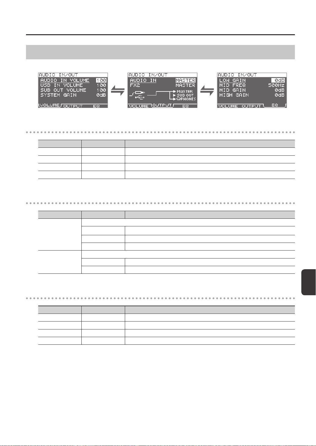
Overall Settings for the SPD-SX
Overall Settings for the SPD-SX
55
Input/Output Settings (AUDIO IN/OUT)
Here you can make settings for input and output.
VOLUME
Parameter Value Explanation
AUDIO IN VOLUME 0–100 Adjusts the volume of the input to the AUDIO IN jacks.
USB IN VOLUME 0–100 Adjusts the volume of the input to the COMPUTER connector.
SUB OUT VOLUME 0–100 Adjusts the volume of the output from the SUB OUT jacks.
SYSTEM GAIN 0dB, 6dB, 12dB Adjusts the overall volume of the SPD-SX.
OUTPUT
Parameter Value Explanation
AUDIO IN
Allows you to select the jack(s) from which the audio arriving at AUDIO IN jacks will be output.
MASTER Output from the MASTER OUT jacks and the PHONES jack.
SUB OUT Output from the SUB OUT jacks and the PHONES jack.
PHONES Output from the PHONES jack.
FX2
Species the jacks from which the sound processed by kit eect FX2 (p. 46) will be output.
MASTER Output from the MASTER OUT jacks and the PHONES jack.
SUB OUT Output from the SUB OUT jacks and the PHONES jack.
EQ
Parameter Value Explanation
LOW GAIN -12–+12dB Adjusts the volume of the low-frequency region.
MID FREQ 20Hz–10kHz Species the center frequency of the region adjusted by EQ MID GAIN.
MID GAIN -12–+12dB Adjusts the volume of the mid-frequency region.
HIGH GAIN -12–+12dB Adjusts the volume of the high-frequency region.
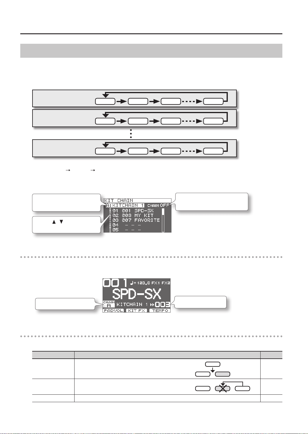
Overall Settings for the SPD-SX
56
Specifying the Kit Switching Order (KIT CHAIN)
The kit chain function lets you specify the order in which kits will be switched. This is very useful in a live performance so you
can step through the kits in the desired order by pressing the [-] [+] buttons, a footswitch or by hitting an external pad set to
operate as a switch (p. 57).
The SPD-SX lets you store eight sets of patch chains, called banks (A–H). Each bank can have 20 steps.
Kit chain bank A
STEP 1 STEP 2 STEP 3 STEP 20
Kit chain bank H
STEP 1 STEP 2 STEP 3
STEP 20
Kit chain bank B
STEP 1 STEP 2 STEP 3 STEP 20
1. Choose MENU SYSTEM KIT CHAIN.
The KIT CHAIN screen will appear.
Use the cursor buttons and the [-] [+] buttons to specify the kit chain.
Use the [-] [+] buttons to turn the
kit chain function on/o.
Use the [-] [+] buttons to select a
kit chain bank.
Use the [ ] [ ] buttons to select
a kit.
Switching a Step
If the kit chain function is on, the top screen will indicate the name of the kit chain bank.
You can use the [-] [+] buttons to switch between the steps you stored.
The kit of the next step
Kit chain bank name
KIT CHAIN screen quick menu
In the KIT CHAIN screen, pressing the [QUICK] button will display the following quick menu.
Menu Explanation Page
INSERT Inserts a new step before the selected step.
-
DELETE
Deletes the selected step, and moves subsequent steps up to ll
the gap.
-
CHAIN NAME Assigns a name to the kit chain bank. p. 47

Overall Settings for the SPD-SX
Overall Settings for the SPD-SX
57
Using a Pad or Footswitch as a Switch (PAD/FS CONTROL)
You can assign a pad to perform a function other than playing a sound. For example, you can play a pad to switch between kits
or turn a kit eect on/o. This is convenient during live performances, since it lets you avoid having to operate the buttons.
* Any pad for which you’ve made PAD/FS CONTROL settings will not produce sound when you play it.
Parameter Value Explanation
FS 1, FS 2, TRIG1–4,
PAD1–9
OFF PAD/FS CONTROL is o.
KIT INC Recalls the next kit.
KIT DEC Recalls the previous kit.
CLICK Turns the click on/o.
TAP TEMPO Sets the tempo by the timing at which you play the pad.
ALL SOUND OFF Stops all currently playing sounds.
FX1 ON/OFF Turns kit eect 1 on/o.
FX2 ON/OFF Turns kit eect 2 on/o.
PAD CHECK
Performs the same operation as the [PAD CHECK] button.
* This can be assigned only to FOOT SW1 or FOOT SW2.
Controlling Images (VISUAL CONTROL)
Visual Control is a function that lets you control images along with your performance.
The SPD-SX lets you do the following when a video device supporting MIDI Visual Control or V-LINK is connected.
• Switch kits in order to switch video materials.
• Control images by turning the [CONTROL 1] knob or [CONTROL 2] knob.
What is the MIDI Visual Control?
MIDI Visual Control is an internationally-used recommended practice that was added to the MIDI specication so that
visual expression could be linked with musical performance. Video equipment that is compatible with MIDI Visual
Control can be connected to electronic musical instruments via MIDI in order to control video equipment in tandem
with a performance.
What is the V-LINK?
V-LINK is a function that allows music and images to be performed together. By using MIDI to connect two or more
V-LINK compatible devices, you can easily enjoy a wide range of visual eects that are linked to the expressive elements
of a music performance.
Example connection
Use a MIDI cable to connect the SPD-
SX’s MIDI OUT connector to the MIDI
IN connector of your Visual Control
compatible device.
MIDI OUT connector
Visual Control
compatible device
MIDI IN connector
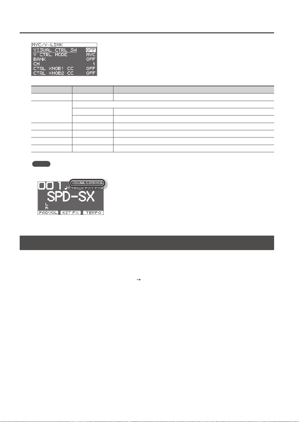
Overall Settings for the SPD-SX
58
Parameter Value Explanation
VISUAL CTRL SW OFF, ON Turns Visual Control on/o.
V CTRL MODE
Choose the setting that's appropriate for the connected device.
MVC Choose this if connecting a video device that supports MIDI Visual Control.
V-LINK Choose this if connecting a video device that supports V-LINK.
BANK OFF, 0–127 Switches the bank.
CH 1–16 Species the MIDI channel used to switch images.
CTRL KNOB1 CC OFF, #1–#95 Turning the [CONTROL 1] knob will transmit a control change message.
CTRL KNOB2 CC OFF, #1–#95 Turning the [CONTROL 2] knob will transmit a control change message.
MEMO
• If the Visual Control function is on, the VISUAL CONTROL icon is shown in the top screen.
• For details on how to switch between images, refer to the owner’s manual of the connected device.
Initializing the System (SYSTEM INIT)
Here you can initialize the SYSTEM parameter settings.
* When you execute SYSTEM INIT, all of the System settings will be lost. If you want to keep these settings, you should save
them to a USB ash drive (p. 66).
1. From the SYSTEM screen, choose QUICK MENU
SYSTEM INIT.
2. Press the [ENTER] button.
A conrmation message will appear.
If you decide to cancel without executing, press the [EXIT] button.
3. Press the [ENTER] button once again, and the System settings will be initialized.
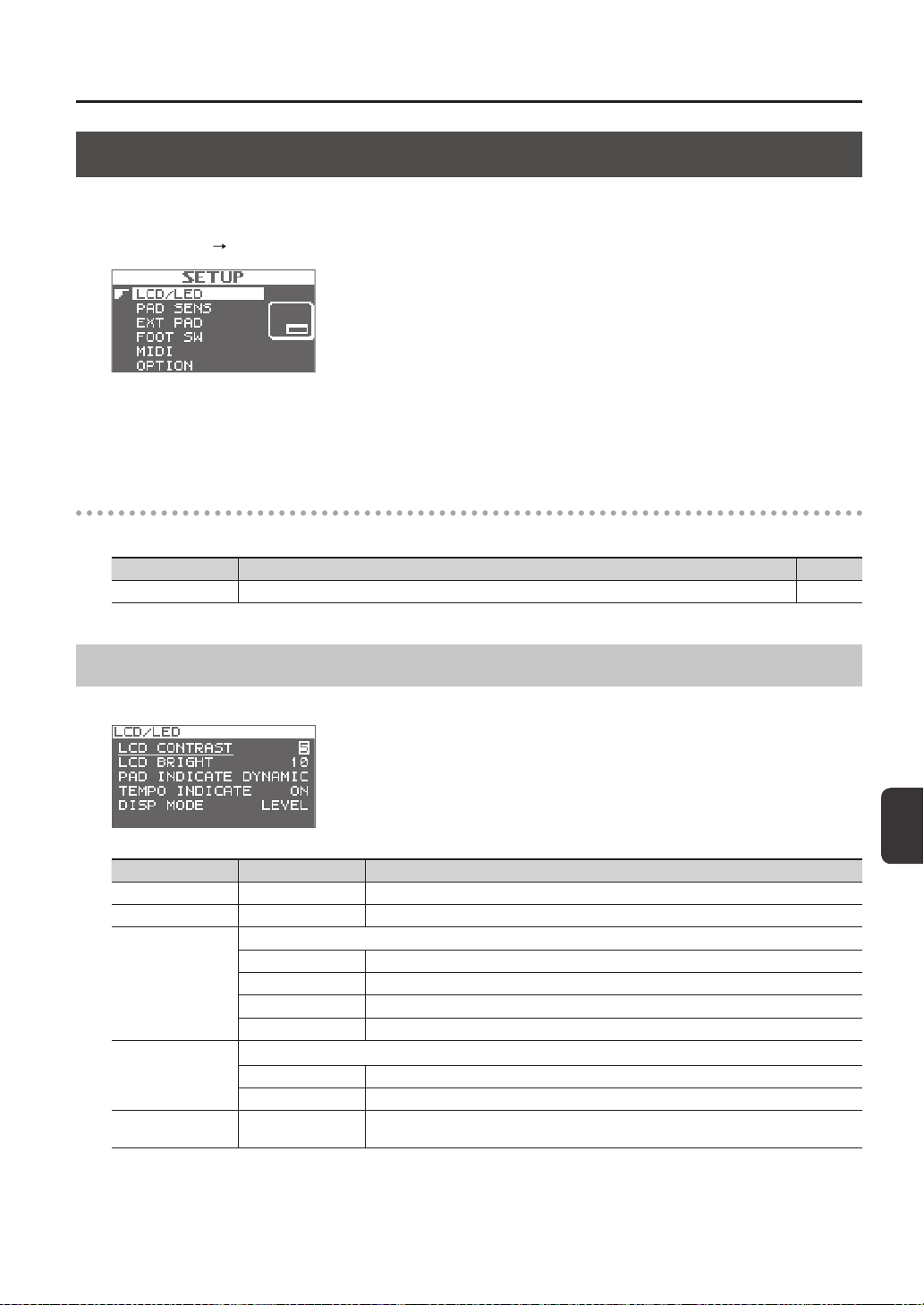
Overall Settings for the SPD-SX
Overall Settings for the SPD-SX
59
Display and Pad Settings (SETUP)
Here you can make display, pad, and MIDI-related settings for the entire SPD-SX. For the procedure, refer to “Basic Editing
Procedure” (p. 16).
1. Choose MENU
SETUP.
2. Choose the item that you want to edit.
3. Edit the parameter.
SETUP screen quick menu
In the SETUP screen, pressing the [QUICK] button will display the following quick menu.
Menu Explanation Page
SETUP INIT Initializes the settings of the Setup parameters. p. 64
Display Brightness and Indicator Settings (LCD/LED)
Here you can adjust the brightness of the display, and specify how the indicators will light.
Parameter Value Explanation
LCD CONTRAST 1–10 Adjusts the contrast of the display.
LCD BRIGHT 1–10 Adjusts the brightness of the display.
PAD INDICATE
Species how the pad indicators will light.
OFF The pad indicators will always stay unlit.
DYNAMIC The pad indicators will light according to the volume of the wave being played.
STATE The pad indicators will light only when you play the pad.
ALL ON The pad indicators will always remain lit.
TEMPO INDICATE
Species how the TEMPO indicator will light.
OFF The TEMPO indicator will stay unlit.
ON The TEMPO indicator will blink at the tempo.
DISP MODE
SUB NAME, LEVEL
Selects whether the sub-name or the level meter will be shown below the kit name in the top
screen.
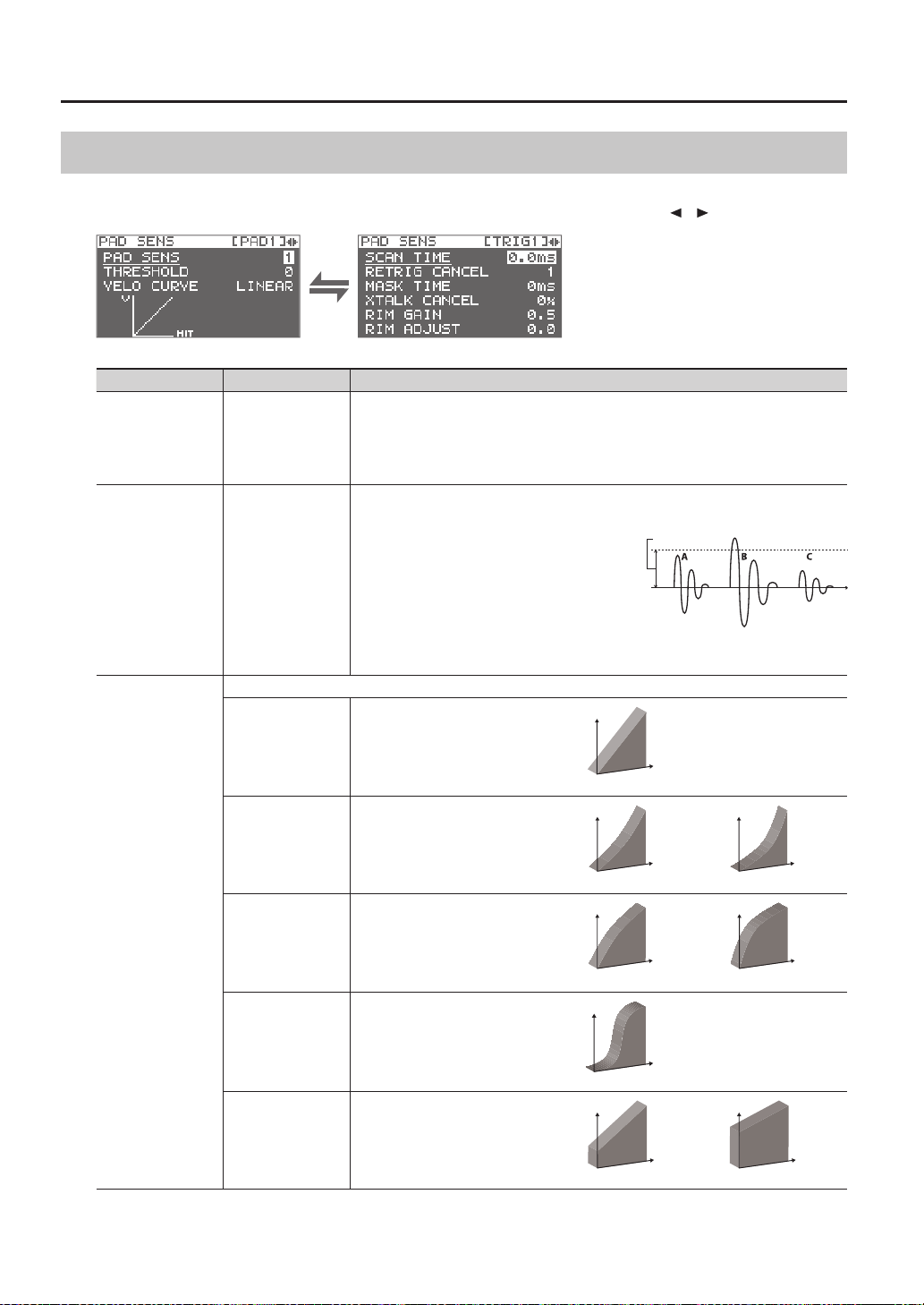
Overall Settings for the SPD-SX
60
Pad Sensitivity Adjustment (PAD SENS)
Here you can adjust the pad sensitivity.
Play a pad to specify the pad that you want to edit. You can also select a pad by using the cursor [
] [ ] buttons.
Parameter Value Explanation
PAD SENS 1–16 (1–32) *1
You can adjust the sensitivity of the pads to accommodate your personal playing style.
This allows you to have more dynamic control over the sound volume, based on how hard you
play.
Higher sensitivity allows the pad to produce a loud volume even when played softly. Lower
sensitivity will keep the pad producing a low volume even when played forcefully.
THRESHOLD 0–15 (0–31) *1
This setting allows a trigger signal to be received only
when the pad is above a determined dynamic level
(velocity). This can be used to prevent a pad from
sounding because of vibrations from other pads.
In the example, B will sound but A and C will not
sound.
When set to a higher value, no sound is produced
when the pad is struck lightly. Gradually raise the
THRESHOLD value while striking the pad.
Check this and adjust accordingly. Repeat this process
until you get the perfect setting for your playing style.
THRESHOLD
VELO CURVE
Adjust this curve until the response feels as natural as possible.
LINEAR
The standard setting. This produces the
most natural correspondence between
playing dynamics and volume change.
LINEAR
Volume
Playing
dynamics
EXP1, EXP2
Compared to LINEAR, strong dynamics
produce a greater change.
EXP1
Volume
Playing
dynamics
Playing
dynamics
EXP2
Volume
LOG1, LOG2
Compared to LINEAR, a soft playing
produces a greater change.
Volume
Playing
dynamics
Playing
dynamics
Volume
LOG1 LOG2
SPLINE
Extreme changes are made in response
to playing dynamics.
Volume
Playing
dynamics
SPLINE
LOUD1, LOUD2
Very little dynamic response, making
it easy to maintain strong volume
levels. If you’re using a drum trigger
as an external pad, these settings will
produce reliable triggering.
Volume
Playing
dynamics
Playing
dynamics
Volume
LOUD1 LOUD2
*1: When editing TRIG1–4, the range of values shown in parentheses will apply.
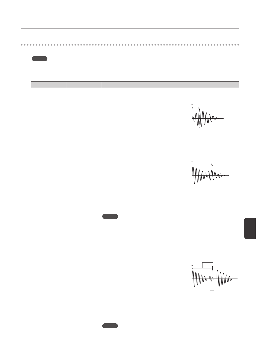
Overall Settings for the SPD-SX
Overall Settings for the SPD-SX
61
DETAIL
Here you can edit the settings for external pads or acoustic drum triggers connected to the TRIG IN jacks (TRIG1–4).
MEMO
When you specify the TRIG1–4 TYPE (p. 62), these parameters are automatically set to the optimal values for the pad type
you’ve specied, so you won’t normally need to edit them. However, you may edit these parameters if you want to make
settings in greater detail.
Parameter Value Explanation
SCAN TIME 0.1–4.0ms
Species the detection time for the trigger signal.
Since the rise time of the trigger signal waveform may dier
slightly depending on the characteristics of each pad or
acoustic drum trigger (drum pickup), you may notice that
identical hits (velocity) may produce sound at dierent
volumes. If this occurs, you can adjust the “Scan Time” so
that your way of playing can be detected more precisely.
While repeatedly hitting the pad at a constant force,
gradually raise the SCAN TIME value from 0.1 msec, until
the resulting volume stabilizes at the loudest level. At this
setting, try both soft and loud hits, and make sure that the
volume changes appropriately.
SCAN TIME
Time
* As the value is set higher, the time it takes for the sound to be played increases. Set this to
the lowest value possible.
RETRIG CANCEL 1–16
This setting prevents spurious re-triggering.
Important if you are using acoustic drum triggers. Such trig-
gers can produce altered waveforms, which may also cause
inadvertent sounding at Point A in the gure (Re-trigger).
This occurs in particular at the decaying edge of the
waveform. RETRIG CANCEL detects such distortion in and
prevents re-triggering from occurring.
While repeatedly striking the pad, raise the RETRIG CANCEL
value until re-triggering no longer occurs.
Time
* Although setting this to a high value prevents retriggering, it then becomes easy for sounds
to be omitted when the drums played fast (roll etc.). Set this to the lowest value possible
while still ensuring that there is no retriggering.
MEMO
You can also eliminate this problem of re-triggering with the MASK TIME setting. MASK TIME
does not detect trigger signals if they occur within the specied amount of time after the
previous trigger signal was received. RETRIG CANCEL detects the attenuation of the trigger
signal level, and triggers the sound after internally determining which trigger signals were
actually generated when the head was struck, while weeding out the other false trigger
signals that need not trigger a sound.
MASK TIME 1–64ms
This setting prevents double triggering.
When playing a kick trigger, the beater can bounce back
and hit the head a second time immediately after the
intended note—with acoustic drums sometimes the beater
stays against the head—is causes a single hit to “double
trigger” (two sounds instead of one). The MASK TIME
setting helps to prevent this. Once a pad has been hit, any
additional trigger signals occurring within the specied
“MASK TIME” (0–64 msec) will be ignored.
Adjust the “MASK TIME” value while playing the pad.
When using a kick trigger, try to let the beater bounce back
and hit the head very quickly, then raise the “MASK TIME”
value until there are no more sounds made by the beater
rebound.
MASK TIME
Time
Sound not
produced
* When set to a high value, it will be dicult to play very quickly. Set this to as low a value as
you can.
MEMO
If two or more sounds are being produced when you hit the head just once, then adjust
RETRIG CANCEL.
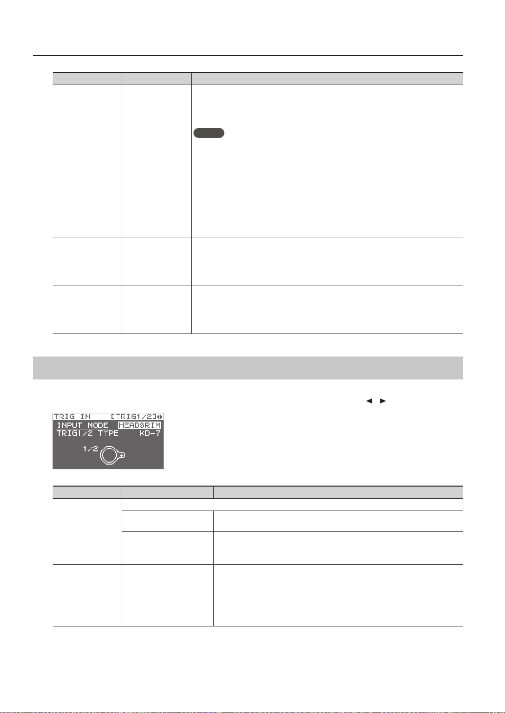
Overall Settings for the SPD-SX
62
Parameter Value Explanation
XTALK CANCEL 0–80%
This setting cancels “crosstalk,” which means that when you play one pad you hear a sound
coming from another pad. This can happen when two pads are installed on the same stand. In
some cases you can prevent crosstalk by increasing the distance between the two mounted
pads.
MEMO
In some cases you can prevent crosstalk by increasing the distance between the two
mounted pads.
Crosstalk Example: If you hit the TRIG IN1 pad and the TRIG IN2 also sounds
While striking the TRIG IN 1 pad, gradually increase the “XTALK CANCEL” value for the TRIG IN2
pad until the TRIG IN2 pad no longer sounds when you hit the TRIG IN1 pad. Raise the “XTALK
CANCEL” for the pad being used for TRIG IN2.
The TRIG IN2 pad will be less prone to receive crosstalk from other pads.
* If the value is set too high, and two pads are played simultaneously, the one that is struck
less forcefully may not sound. Be careful and set this parameter to the minimum value
required to prevent crosstalk.
RIM GAIN 0.0–8.0
When a PD-125/120/105/85/80R, PDX-8, PD-9/8/7, CY series pad, or RT-10S is connected,
you can adjust the relation between your playing velocity (force) on the rim/edge and the
resulting volume level.
Higher value allows the rim/edge to produce a loud volume even when played softly. Lower
value will keep the rim/edge producing a low volume even when played forcefully.
RIM ADJUST 0.0–8.0
When a PD-125/120/105/85/80R, PDX-8, or RT-10S is connected, you can adjust the sensitivity
of the rim response.
There are some cases that you have a rim sound unexpectedly when you hit the head
strongly. You can improve this situation with decreasing the value of “Rim Adjust.” When you
set the value too small, it might be dicult to play the rim sound.
External Pad Settings (TRIG IN)
Here you can make settings for external pads connected to the TRIG IN jacks.
Play a pad to specify the pad that you want to edit. You can also select a pad by using the cursor
[
] [ ] buttons.
Parameter Value Explanation
INPUT MODE
Select whether or not to use rim-shot.
HEAD&RIM
To connect a single pad with rim-shot/edge-shot/bell-shot features (PD-8, PDX-6, PDX-
8, PD-85, PD-105, PD-105X, PD-125, PD-125X, CY-5, CY-9, CY-14C, CY-12R/C, CY-15R).
TRIGx2
To connect two devices like pads and kick triggers.
* When two pads are connected, the rim-shot/edge-shot/bell-shot features are
unavailable.
TRIG1–4 TYPE
KD-7, KD-8, KD-9, KD-85,
KD-120, KD-140, PD-8,
PDX-6, PDX-8, PD-85, PD-105,
PD-105X, PD-125, PD-125X,
CY-5, CY-8, CY-12C, CY-13R,
CY-12RC, CY-14C, CY-15R,
RT-10K, RT-10S, RT-10T
For each Pad, you can select the type of pad you’re using (the pad type) so the SPD-SX
will accurately receive the signal from the pad.
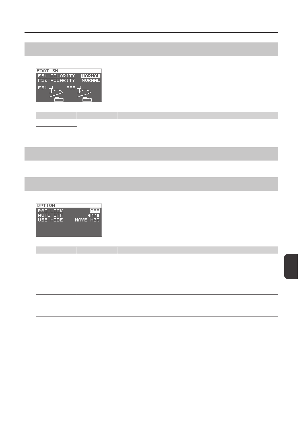
Overall Settings for the SPD-SX
Overall Settings for the SPD-SX
63
Footswitch Settings (FOOT SW)
Here you can make settings for footswitches connected to the FOOT SW jack.
Parameter Value Explanation
FS1 POLARITY
NORMAL, INVERSE
This is a footswitch polarity switch. Change this setting if the footswitch does not operate as
you expect.
FS2 POLARITY
MIDI Settings (MIDI)
Here you can make MIDI settings for the entire SPD-SX. Refer to “MIDI Settings for the Entire SPD-SX (MIDI)” (p. 68).
Other Settings (OPTION)
Here you can make various other settings.
Parameter Value Explanation
PAD LOCK OFF, ON
If this is “ON,” playing a pad in the KIT PAD screen (p. 44) will not select the pad for editing. This is
convenient when you want to check the sound of other pads while you edit.
AUTO OFF OFF, 4hrs
The SPD-SX has an auto-o function that automatically turns o the power when no
operation has been performed for 4 hours.
Auto-o will occur if no pad is struck and no operation is performed for the duration of time
specied by “AUTO OFF”; the power will turn o automatically. (With the factory settings, the
auto-o function is turned “OFF.”)
USB MODE
Species the mode of operation when the SPD-SX is connected via a USB cable to a computer.
WAVE MGR Choose this setting when using “SPD-SX Wave Manager,” provided on the included CD-ROM.
AUDIO/MIDI Choose this setting when using USB audio and USB MIDI.
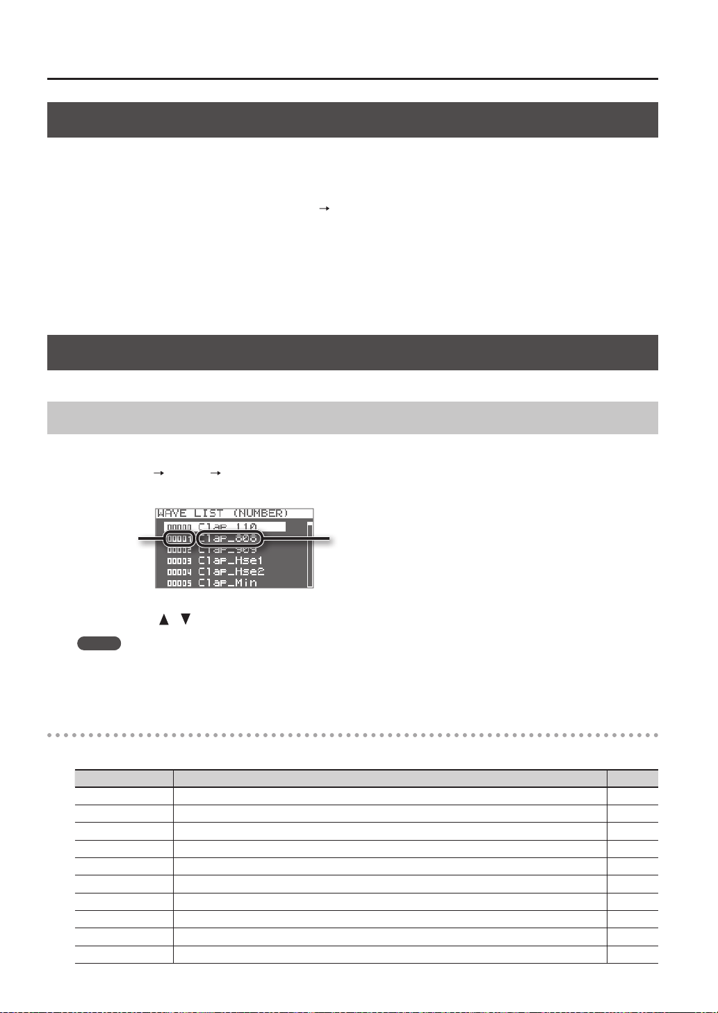
Overall Settings for the SPD-SX
64
Initializing the Setup Parameters (SETUP INIT)
This initializes the SETUP parameters.
* When you execute SETUP INIT, all the SETUP settings will be lost. If you want to keep these settings, back them up to a USB
ash drive before you continue (p. 66).
1. From the SETUP screen, choose QUICK MENU
SETUP INIT.
2. Press the [ENTER] button.
A conrmation message will appear.
If you decide to cancel without executing, press the [EXIT] button.
3. When you press the [ENTER] button once again.
The Setup settings will be initialized.
Other Convenient Functions (UTILITY)
Here you can view information about the waves and the SPD-SX itself, and transfer data using a USB ash drive.
Viewing the Wave List (WAVE LIST)
Here’s how to view the list of waves.
1. Choose MENU
UTILITY WAVE LIST.
The WAVE LIST screen will appear.
Wave nameWave number
2. Use the cursor [ ] [ ] buttons to view the waves.
MEMO
• You can use the quick menu to choose how the waves are displayed; for example, by category.
• To sound the currently selected wave, press the [PAD CHECK] button. Press the [PAD CHECK] button once again to stop the
wave that’s playing.
WAVE LIST screen quick menu
In the WAVE LIST screen, pressing the [QUICK] button will display the following quick menu.
Menu Explanation Page
NUMBER LIST Waves in the WAVE LIST screen are sorted by wave number. -
ABC LIST Waves in the WAVE LIST screen are sorted alphabetically. -
CATEGORY Waves in the WAVE LIST screen are sorted by category. -
ASSIGN LIST Waves in the WAVE LIST screen are sorted by kit. -
WAVE NAME Renames a wave. p. 47
WAVE CATEGORY Registers the waves with category. p. 51
RENUMBER Renumbers the waves. p. 52
WAVE COPY Copies a wave. p. 52
WAVE DELETE Deletes a wave. p. 52
WAVE EXPORT Saves a wave to USB ash drive. p. 52
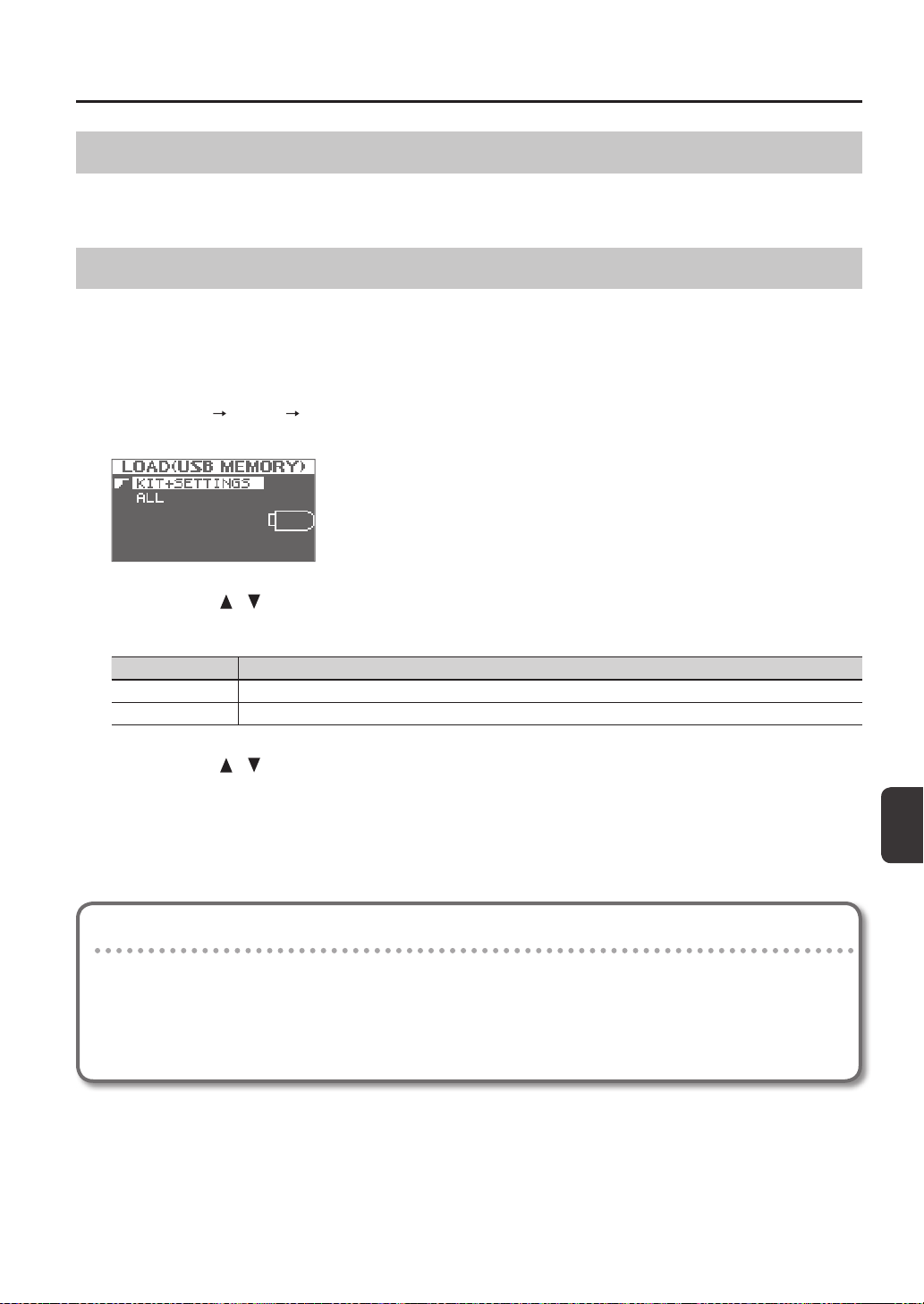
Overall Settings for the SPD-SX
Overall Settings for the SPD-SX
65
Importing an Audio File from a USB Flash Drive (WAVE IMPORT)
An audio le from a USB ash drive can be imported into the SPD-SX as a wave.
Refer to “Importing Audio Files from a USB Flash Drive (WAVE IMPORT)” (p. 39).
Loading Data from a USB Flash Drive (LOAD (USB MEMORY))
Here you can load data that you previously saved to a USB ash drive.
* When you execute the LOAD (USB MEMORY) operation, the data in the SPD-SX will be overwritten. If the SPD-SX contains
important data that you want to keep, save it to a USB ash drive before you proceed (p. 66).
1. Connect your USB ash drive to the USB MEMORY connector (p. 18).
2. Choose MENU
UTILITY LOAD (USB MEM).
The LOAD (USB MEMORY) screen will appear.
3. Use the cursor [ ] [ ] buttons to select the command that you want to execute, and then press the [ENTER]
button.
Item Explanation
KIT+SETTINGS Kits and SPD-SX settings will be loaded.
ALL All data (waves, kits, and SPD-SX settings) will be loaded.
4. Use the cursor [
] [ ] buttons to select the data that you want to load, and then press the [ENTER] button.
A conrmation message will appear.
If you decide to cancel without executing, press the [EXIT] button.
5. Press the [ENTER] button.
The data will be loaded.
Restoring All the Factory Default Settings
If you want to return the SPD-SX to its factory-set state, save the factory settings le to your USB ash drive, and then
execute “ALL.”
The factory settings le can be obtained from the Roland website.
Visit the following URL, search for the model name “SPD-SX.”
http://www.roland.com/support/en/
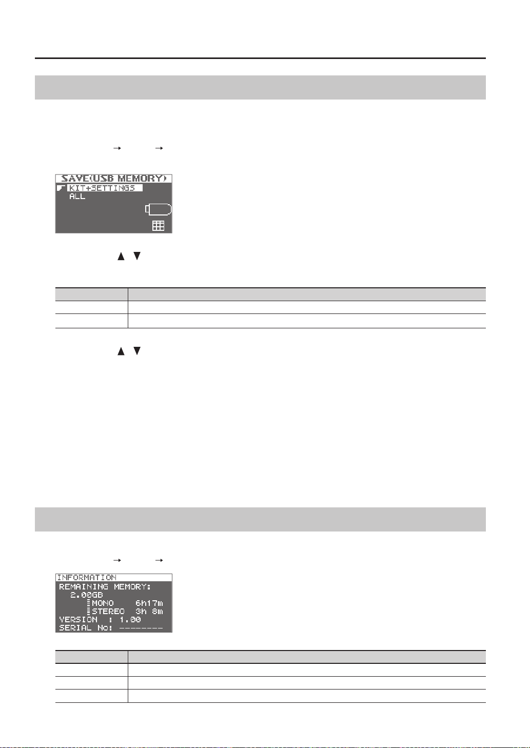
Overall Settings for the SPD-SX
66
Saving Data to a USB Flash Drive (SAVE (USB MEMORY))
Here’s how to save the SPD-SX’s waves and settings to a USB ash drive.
1. Connect your USB ash drive to the USB MEMORY connector (p. 18).
2. Choose MENU
UTILITY SAVE (USB MEM).
The SAVE (USB MEMORY) screen will appear.
3. Use the cursor [ ] [ ] buttons to select the item that you want to execute, and then press the [ENTER]
button.
Item Explanation
KIT+SETTINGS Kits and SPD-SX settings will be saved.
ALL All data (waves, kits, and SPD-SX settings) will be saved.
4. Use the cursor [
] [ ] buttons to select the save destination, and press the [ENTER] button.
If you want to create newly saved data, choose “SAVE AS...”
If you want to overwrite previously saved data, select the data that you want to overwrite.
If you selected the previously saved data, proceed to step 6.
5. Assign a name to the data (p. 47).
6. Press the [ENTER] button.
A conrmation message will appear.
If you decide to cancel without executing, press the [EXIT] button.
7. Press the [ENTER] button.
The data will be saved.
Viewing Information About the SPD-SX Itself (INFORMATION)
Here you can view information about the SPD-SX itself, such as the remaining amount of internal memory.
1. Choose MENU
UTILITY INFORMATION.
Item Explanation
REMAINING MEMORY Indicates the amount of memory remaining and the available sampling time.
VERSION Indicates the program version being used.
SERIAL NO Indicates the serial number.
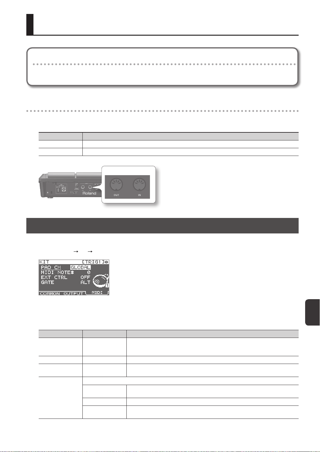
Connecting an External MIDI Device
67
Connecting an External MIDI Device
About MIDI
MIDI (Musical Instrument Digital Interface) is a standard specication that allows musical data to be transferred between
electronic musical instruments and computers.
About the MIDI connectors
MIDI messages are exchanged using the MIDI connectors. Connect MIDI cables to these connectors as appropriate for your
setup.
MIDI connector Explanation
MIDI IN connector Receives MIDI messages sent by an external MIDI device.
MIDI OUT connector Transmits MIDI messages from the SPD-SX.
MIDI connector
MIDI Settings for Each Pad (MIDI)
Here you can make MIDI settings for each pad. For details on the procedure, refer to “Basic Editing Procedure” (p. 16).
1. Choose MENU
KIT MIDI.
2. Select the item that you want to set.
3. Edit the parameter.
Parameter Value Explanation
PAD CH GLOBAL, 1–16
Allows you to set the channel on which transmission/reception takes place, on an individual
pad basis. When set to "GLOBAL," transmission/reception will take place on the channel that's
been set for GLOBAL CH (p. 68).
MIDI NOTE# OFF, 0–127 Species the note number transmitted from the MIDI OUT connector.
EXT CTRL OFF, ON
When set to "ON," notes will be transmitted in accordance with the setting for GATE. At this
time, no sound will be produced when you play the pads.
GATE
Species how notes will be transmitted.
OFF
A note-o will be transmitted immediately after a note-on is transmitted. Choose this setting
if using the SPD-SX to play an external drum sound module.
ALT A note-on and note-o will be transmitted alternately each time you play the pad.
0.1–8.0S
A note-o will be transmitted after the gate time (note length) you specify. The gate time can
be adjusted in 0.1 second steps.
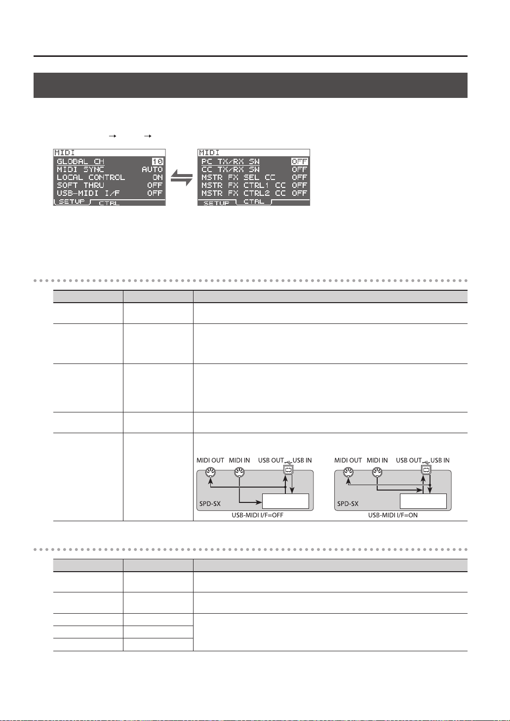
Connecting an External MIDI Device
68
MIDI Settings for the Entire SPD-SX (MIDI)
Here you can make overall MIDI settings that apply to the entire SPD-SX. For details on the procedure, refer to “Basic Editing
Procedure” (p. 16).
1. Choose MENU
SETUP MIDI.
2. Select the item that you want to set.
3. Edit the parameter.
SETUP
Parameter Value Explanation
GLOBAL CH OFF, 1–16
Species the transmit and receive channel. If you choose "OFF," MIDI messages will not be
transmitted.
MIDI SYNC OFF, AUTO
Species whether to synchronize the SPD-SX’s playback tempo.
If you choose “AUTO,” MIDI clock (F8) messages received via the MIDI IN connector or
the COMPUTER connector will be detected automatically, and the SPD-SX’s tempo will
synchronize to these messages.
LOCAL CONTROL OFF, ON
Local Control is a setting used when recording your pad performance into an external MIDI
sequencer.
When recording, turn LOCAL CONTROL “OFF” so that when you play the pads, the perfor-
mance data will not be sent directly to the SPD-SX’s internal sound generator, but will be
routed through the external sequencer and then sent back to the SPD-SX.
SOFT THRU OFF, ON
If this is “ON,” data received at the MIDI IN connector will also be transmitted from the MIDI
OUT connector along with the performance data of the SPD-SX itself.
USB-MIDI I/F OFF, ON
If this is “ON,” MIDI messages transmitted or received via the COMPUTER connector will be
transmitted and received without change via the MIDI connectors.
Internal sound
generator
Internal sound
generator
CTRL
Parameter Value Explanation
PC TX/RX SW OFF, ON
Enables (ON) or disables (OFF) transmission and reception of program change messages
between the SPD-SX and an external MIDI device.
CC TX/RX SW OFF, ON
Enables (ON) or disables (OFF) transmission and reception of control change messages
between the SPD-SX and an external MIDI device.
MASTER FX SEL CC OFF, #01–#95
The control change message specied here will be transmitted and received. If this is “OFF,” no
MIDI message will be transmitted and received.
MASTER FX CTRL1 CC OFF, #01–#95
MASTER FX CTRL2 CC OFF, #01–#95
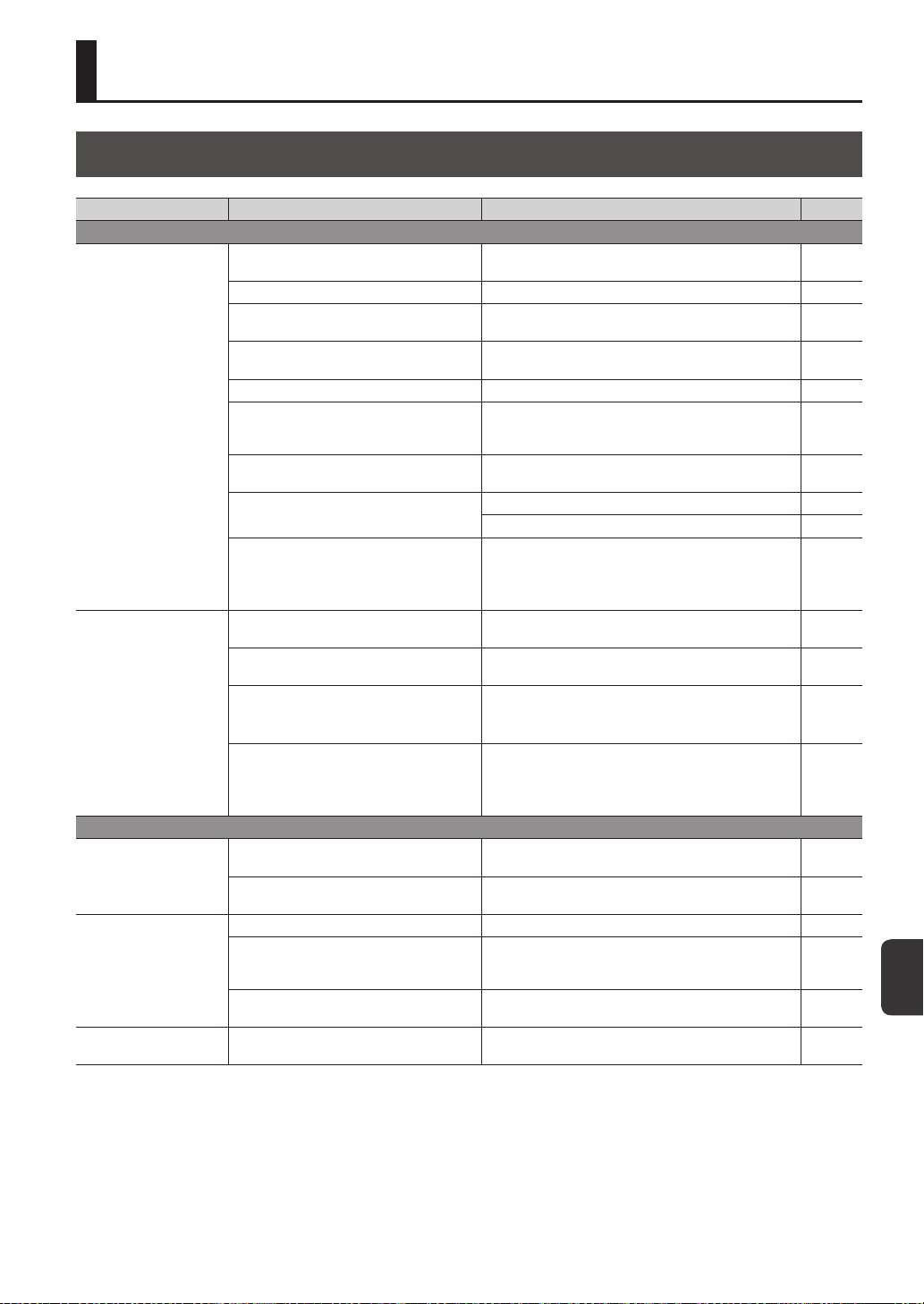
Appendix
69
Appendix
Troubleshooting
Problem Items to check Action Page
Problems with the sound
No sound / Insucient
volume
Is the SPD-SX correctly connected to the
external devices?
Check the connections. p. 12
Could an audio cable be broken? Try using a dierent cable -
Could you be using a connection cable that
contains a resistor?
Use a connection cable that does not contain a resistor. -
Could the volume of the connected amp or
mixer be lowered?
Adjust the volume to an appropriate level. -
Could the SPD-SX’s volume be lowered? Adjust the volume to an appropriate level. p. 15
Check whether you hear sound through
headphones.
If you hear sound in the headphones, there is a problem
with the connection cables or with the connected amp or
mixer. Check the connected devices and the connections
-
Could the volume be lowered on the device
connected to the AUDIO IN jacks?
Adjust the volume to an appropriate level. -
Is the input level low?
Turn the [GAIN] knob to an appropriate level. p. 29
Adjust the AUDIO IN VOLUME to an appropriate setting. p. 55
Could LOCAL CONTROL be "OFF"?
If LOCAL CONTROL is “OFF,” playing the pads will not send
performance data directly to the SPD-SX’s internal sound
generator.
Set LOCAL CONTROL to “ON.”
p. 68
Certain pads don’t sound
Could the level of the wave or sub-wave be
lowered?
Adjust the level of the wave or sub-wave. p. 45, p. 46
Have the settings for OUTPUT been made
correctly?
Check the settings for OUTPUT. p. 43
Have you made settings for PAD/FS CONTROL?
Any pad for which you've made PAD/FS CONTROL settings
will not produce sound when you play it.
Set PAD/FS CONTROL to “OFF.”
p. 57
Could EXT CTRL be set to "ON"?
When EXT CTRL is set to "ON," the unit is placed in the
mode whereby control change messages are transmitted/
received, so no sound will be produced if you play a pad.
Set EXT CTRL to “OFF.”
p. 67
Problems with USB
USB ash drive is inserted,
but is not detected /
Cannot select data
Is the USB ash drive inserted correctly? Make sure that the USB ash drive is correctly connected. p. 18
Is the USB ash drive of a correct type?
Use USB Flash Memory sold by Roland. We cannot
guarantee operation if other products are used.
-
Can't communicate with
the computer
Is the USB cable connected correctly? Make sure that the USB cable is correctly connected. p. 19
Is the USB driver installed?
The USB driver is required in order for you to use USB audio
or USB MIDI. You must rst install the USB driver on your
computer.
p. 19
Have the settings for USB MODE been made
correctly?
Choose the setting that’s appropriate for your situation. p. 63
Can't load a WAV le
Are the le name and format of the WAV le
correct?
Check the le name and format of the WAV le. p. 39
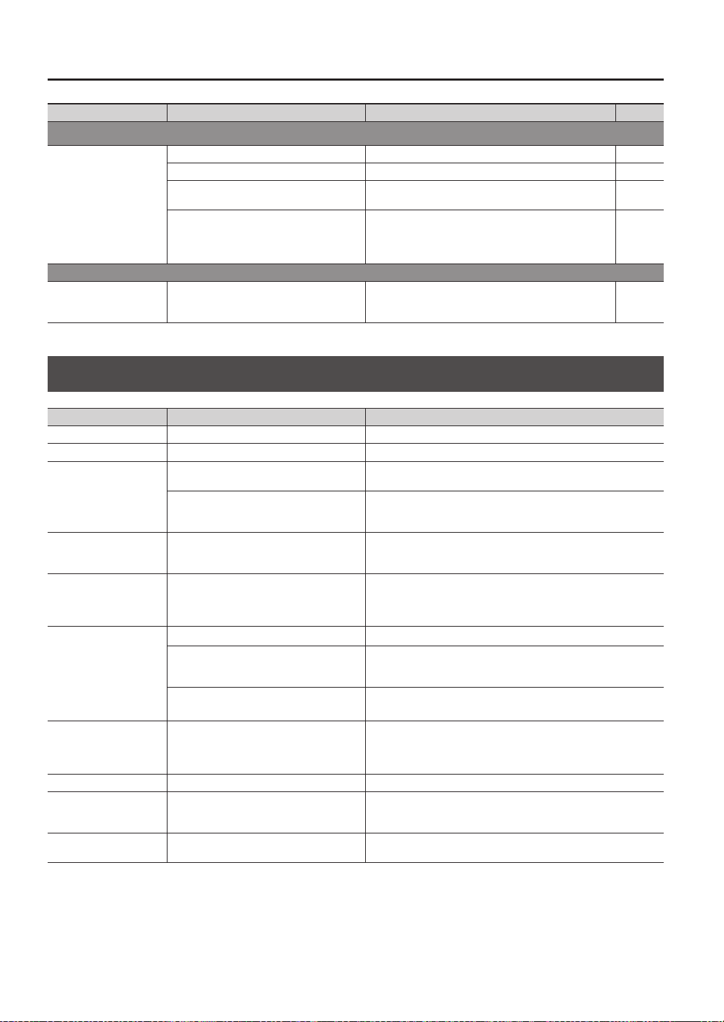
Appendix
70
Problem Items to check Action Page
Problems with MIDI
No sound
Are the MIDI cables connected correctly? Check the connections. p. 67
A MIDI cable may be broken. Try using a dierent cable -
Is the MIDI channel set correctly?
Set the MIDI channels of the SPD-SX and external MIDI
device to the same setting
p. 67
Has the note number been set properly?
When a note number that is not assigned to any pad is
received, the SPD-SX produces no sound. Change the note
number value or switch over to a kit to which another note
number is assigned.
p. 67
Other problems
Display contrast is
inconsistent
In some cases, the contrast of the display
might not be consistent, but this is not a
malfunction.
Adjusts the contrast of the display. p. 59
Error Message List
Problem Items to check Action
DATA ERROR The data on the USB ash drive is damaged. Do not use this le.
MEMORY DAMAGED There is a problem with internal memory. Initialize the memory as directed by the message in the screen.
MEMORY FULL
There is insucient free space on the USB ash
drive.
Delete unneeded data.
The memory has insucient free space for
sampling. And the requested operation cannot
be executed.
Delete unneeded wave.
MIDI BUFFER FULL
A large amount of MIDI messages was received
in a short time, and the SPD-SX was unable to
process them all.
Make sure that the external MIDI device is correctly connected. If this
does not solve the problem, decrease the amount of MIDI messages
being transmitted to the SPD-SX.
MIDI OFFLINE
The MIDI cable or USB cable was disconnected.
Alternatively, communication with the external
MIDI device has been interrupted for some
reason.
Check whether the MIDI cable or USB cable could have been discon-
nected or broken.
NO USB MEMORY
USB ash drive is not connected. Connect USB ash drive to the USB MEMORY connector.
The specied data was not found in the USB
ash drive. Alternatively, the saved data is
damaged.
Do not use this le.
The USB ash drive is not working correctly.
Make sure that the USB ash drive is correctly connected (p. 18).
Make sure that you’re using a USB Flash Memory sold by Roland.
REMOVE THE USB DEVICE
A USB device that the SPD-SX cannot handle
is connected, or a foreign object may have
entered the USB MEMORY connector, causing
a short circuit.
Immediately disconnect the connection, and check that no foreign
object has entered the USB MEMORY connector.
SYSTEM ERROR There is a problem with the internal system. Please contact your dealer.
TRANSMIT BUFFER FULL
An excessive amount of data was transmitted
from the SPD-SX, and could not be correctly
output from MIDI OUT connector.
Decrease the amount of data being transmitted, for example by
decreasing the data.
UNSUPPORTED FORMAT
This WAV or AIFF le is not supported by the
SPD-SX.
Do not use this le.
Appendix
Appendix
71
Specications
Roland SPD-SX: SAMPLING PAD
Pads
Built-in pads: 9 (with LED indicators)
* Two external trigger inputs are provided, allowing you to connect up to four pads.
Maximum Polyphony
20 voices
* Maximum polyphony becomes 16 voices according as an operating state.
Recordable Wave Data
10,000
* Including preload wave data.
Sampling Time
(Total time for all wave data)
Approx. 180 min. in stereo (360 min. in mono)
* Since the internal memory included with the SPD-SX contains preload data, the available sampling time will be less
than the time above.
Data Format 16-bit linear PCM (WAV / AIFF)
Sampling Frequency 44.1 kHz
Kits 100
Kit Chain 8 chains (20 steps per chain)
Eects
Master Eects (21 types)
Equalizer
Kit Eect 1 (20 types)
Kit Eect 2 (20 types)
Display Graphic LCD 128 x 64 dots
Connectors
PHONES jack (Stereo 1/4 inch phone type)
MASTER OUT jacks (L /MONO, R) (1/4 inch phone type)
SUB OUT jacks (L /MONO, R) (1/4 inch phone type)
AUDIO IN jacks (L /MONO, R) (1/4 inch phone type) (with LINE-MIC GAIN control)
TRIG IN jacks (1/2, 3/4) (1/4 inch TRS phone type)
FOOT SW jack (1/2) (1/4 inch TRS phone type)
MIDI connectors (IN, OUT)
DC IN jack
COMPUTER connector
USB MEMORY connector
Interface Hi-Speed USB (USB-MIDI, USB-AUDIO, USB Mass Storage Class, USB Flash Drive)
Power Supply DC 9 V (AC Adaptor)
Current Draw 600 mA
Dimensions
363.7 (W) x 331.0 (D) x 94.1 (H) mm
14-5/16 (W) x 13-1/16 (D) x 3-3/4 (H) inches
Weight 2.5 kg / 5 lbs 9 oz (excluding AC Adaptor)
Accessories
CD-ROM (SPD-SX Wave Manager, USB driver, preload wave data)
Owner’s Manual
AC Adaptor
Options (sold separately)
Pads (PD series, PDX series)
Cymbals (CY series)
Kick Triggers (KD series)
Pad Stand (PDS-10)
All-Purpose Clamp (APC-33)
Acoustic Drum Trigger (RT-10K, RT-10S, RT-10T)
Pedal Switch (DP-2)
Footswitch (FS-5U, FS-6)
Personal Drum Monitor (PM-10, PM-30)
USB Flash Memory
* Use USB Flash Memory sold by Roland. We cannot guarantee operation if other USB ash drive is used.
* 0dBu=0.775Vrms
* In the interest of product improvement, the specications and/or appearance of this unit are subject to change without
prior notice.

72
Index
Symbol
[-] [+] buttons . . . . . . . . . . . . . . . . . . . . . . . . . . . 11
A
AC adaptor . . . . . . . . . . . . . . . . . . . . . . . . . . . . . 12
All-purpose clamp . . . . . . . . . . . . . . . . . . . . . . 14
[ALL SOUND OFF] button . . . . . . . . . . . . 11, 20
APC-33 . . . . . . . . . . . . . . . . . . . . . . . . . . . . . . . . . 14
Audio le . . . . . . . . . . . . . . . . . . . . . . . . . . . . . . . 39
AUDIO IN . . . . . . . . . . . . . . . . . . . . . . . . . . . . . . . 55
AUDIO IN jacks . . . . . . . . . . . . . . . . . . . . . . . . . . 13
AUDIO IN/OUT . . . . . . . . . . . . . . . . . . . . . . . . . . 55
AUDIO IN VOLUME . . . . . . . . . . . . . . . . . . . . . . 55
AUTO OFF . . . . . . . . . . . . . . . . . . . . . . . . . . . . . . 63
B
BANK . . . . . . . . . . . . . . . . . . . . . . . . . . . . . . . . . . . 58
BASIC SAMPLING. . . . . . . . . . . . . . . . . . . . . . . . 29
C
CC TX/RX SW . . . . . . . . . . . . . . . . . . . . . . . . . . . . 68
CH . . . . . . . . . . . . . . . . . . . . . . . . . . . . . . . . . . . . . . 58
CHOP . . . . . . . . . . . . . . . . . . . . . . . . . . . . . . . . . . . 36
CLICK . . . . . . . . . . . . . . . . . . . . . . . . . . . . . . . . . . . 54
[CLICK] knob . . . . . . . . . . . . . . . . . . . . . . . . 11, 24
Click sound . . . . . . . . . . . . . . . . . . . . . . . . . 24, 54
COMMON. . . . . . . . . . . . . . . . . . . . . . . . . . . . . . . 42
Computer . . . . . . . . . . . . . . . . . . . . . . . . . . 19, 40
COMPUTER connector . . . . . . . . . . . . . . . . . . 12
[CONTROL 1] knob . . . . . . . . . . . . . . . . . . 11, 23
[CONTROL 2] knob . . . . . . . . . . . . . . . . . . 11, 23
Copy
Kit . . . . . . . . . . . . . . . . . . . . . . . . . . . . . . . . . . 48
Pad . . . . . . . . . . . . . . . . . . . . . . . . . . . . . . . . . 48
CTRL KNOB1 CC . . . . . . . . . . . . . . . . . . . . . . . . . 58
CTRL KNOB2 CC . . . . . . . . . . . . . . . . . . . . . . . . . 58
Cursor buttons . . . . . . . . . . . . . . . . . . . . . . . . . . 11
D
DC IN jack . . . . . . . . . . . . . . . . . . . . . . . . . . . . . . 12
[DELAY] button . . . . . . . . . . . . . . . . . . . . . 11, 22
DETAIL . . . . . . . . . . . . . . . . . . . . . . . . . . . . . . . . . . 61
Display . . . . . . . . . . . . . . . . . . . . . . . . . . . . . . . . . 11
DISP MODE . . . . . . . . . . . . . . . . . . . . . . . . . . . . . 59
Drum set . . . . . . . . . . . . . . . . . . . . . . . . . . . . . . . 14
DYNAMICS . . . . . . . . . . . . . . . . . . . . . . . . . . . . . . 45
E
Eect . . . . . . . . . . . . . . . . . . . . . . . . . . . . . . . . . . . . 6
Kit eect . . . . . . . . . . . . . . . . . . . . . . . . . . . . 46
Master eect . . . . . . . . . . . . . . . . . . . . . . . . 53
[ENTER] button . . . . . . . . . . . . . . . . . . . . . . . . . 11
EQ . . . . . . . . . . . . . . . . . . . . . . . . . . . . . . . . . . . . . . 55
Error message . . . . . . . . . . . . . . . . . . . . . . . . . . 70
[EXIT] button . . . . . . . . . . . . . . . . . . . . . . . . . . . 11
EXT CTRL . . . . . . . . . . . . . . . . . . . . . . . . . . . . . . . 67
External pad . . . . . . . . . . . . . . . . . . . . . . . . 13, 27
F
Factory reset . . . . . . . . . . . . . . . . . . . . . . . . . . . . 65
[FILTER] button. . . . . . . . . . . . . . . . . . . . . . 11, 22
FOOT SW . . . . . . . . . . . . . . . . . . . . . . . . . . . . . . . 63
FOOT SW indicators . . . . . . . . . . . . . . . . . . . . . 11
Footswitch . . . . . . . . . . . . . . . . . . . . . . . . . . 13, 27
FOOT SW jack . . . . . . . . . . . . . . . . . . . . . . . 13, 27
FS1 POLARITY . . . . . . . . . . . . . . . . . . . . . . . . . . . 63
FS2 POLARITY . . . . . . . . . . . . . . . . . . . . . . . . . . . 63
Function buttons . . . . . . . . . . . . . . . . . . . . . . . 11
FX2 . . . . . . . . . . . . . . . . . . . . . . . . . . . . . . . . . . . . . 55
[FX] button . . . . . . . . . . . . . . . . . . . . . . . . . 11, 22
G
[GAIN] knob . . . . . . . . . . . . . . . . . . . . . . . . . . . . 13
GATE . . . . . . . . . . . . . . . . . . . . . . . . . . . . . . . . . . . 67
GLOBAL CH . . . . . . . . . . . . . . . . . . . . . . . . . . . . . 68
H
Headphones . . . . . . . . . . . . . . . . . . . . . . . . . . . . 13
HIGH GAIN . . . . . . . . . . . . . . . . . . . . . . . . . . . . . . 55
I
INFORMATION . . . . . . . . . . . . . . . . . . . . . . . . . . 66
Initialize
Kit . . . . . . . . . . . . . . . . . . . . . . . . . . . . . . . . . . 49
Pad . . . . . . . . . . . . . . . . . . . . . . . . . . . . . . . . . 49
SETUP . . . . . . . . . . . . . . . . . . . . . . . . . . . . . . 64
SYSTEM . . . . . . . . . . . . . . . . . . . . . . . . . . . . . 58
INPUT MODE . . . . . . . . . . . . . . . . . . . . . . . . . . . . 62
INTERVAL . . . . . . . . . . . . . . . . . . . . . . . . . . . . . . . 54
K
Kit . . . . . . . . . . . . . . . . . . . . . . . . . . . . . . . . . . . . . . 21
Copy. . . . . . . . . . . . . . . . . . . . . . . . . . . . . . . . 48
Customize . . . . . . . . . . . . . . . . . . . . . . . . . . 42
Initialize . . . . . . . . . . . . . . . . . . . . . . . . . . . . 49
KIT . . . . . . . . . . . . . . . . . . . . . . . . . . . . . . . . . . . 5, 42
[KIT] button . . . . . . . . . . . . . . . . . . . . . . . . . . . . . 11
KIT CHAIN . . . . . . . . . . . . . . . . . . . . . . . . . . . . . . 56
Kit eect . . . . . . . . . . . . . . . . . . . . . . . . . . . . 23, 46
KIT FX . . . . . . . . . . . . . . . . . . . . . . . . . . . . . . . . 6, 46
KIT INIT . . . . . . . . . . . . . . . . . . . . . . . . . . . . . . . . . 49
KIT PAD . . . . . . . . . . . . . . . . . . . . . . . . . . . . . . . . . 44
KIT TEMPO . . . . . . . . . . . . . . . . . . . . . . . . . . . . . . 42
KIT VOLUME . . . . . . . . . . . . . . . . . . . . . . . . . . . . 42
L
LCD BRIGHT . . . . . . . . . . . . . . . . . . . . . . . . . . . . . 59
LCD CONTRAST . . . . . . . . . . . . . . . . . . . . . . . . . 59
LCD/LED . . . . . . . . . . . . . . . . . . . . . . . . . . . . . . . . 59
LOAD (USB MEMORY) . . . . . . . . . . . . . . . . . . . 65
LOCAL CONTROL . . . . . . . . . . . . . . . . . . . . . . . . 68
LOOP . . . . . . . . . . . . . . . . . . . . . . . . . . . . . . . . . . . 45
LOW GAIN . . . . . . . . . . . . . . . . . . . . . . . . . . . . . . 55
M
MAIN . . . . . . . . . . . . . . . . . . . . . . . . . . . . . . . . . . . 45
MASK TIME . . . . . . . . . . . . . . . . . . . . . . . . . . . . . 61
Master eect . . . . . . . . . . . . . . . . . . . . . . . . . . . . 22
MASTER EFFECT . . . . . . . . . . . . . . . . . . . . . . . 6, 53
MASTER FX CTRL1 CC . . . . . . . . . . . . . . . . . . . 68
MASTER FX CTRL2 CC . . . . . . . . . . . . . . . . . . . 68
MASTER FX SEL CC . . . . . . . . . . . . . . . . . . . . . . 68
[MASTER] knob . . . . . . . . . . . . . . . . . . . . . . . . . 11
MASTER OUT jacks . . . . . . . . . . . . . . . . . . . . . . 13
[MENU] button . . . . . . . . . . . . . . . . . . . . . . . . . . 11
MERGE . . . . . . . . . . . . . . . . . . . . . . . . . . . . . . . . . 34
Metronome . . . . . . . . . . . . . . . . . . . . . . . . . . . . . 24
Microphone . . . . . . . . . . . . . . . . . . . . . . . . . . . . 13
MID FREQ . . . . . . . . . . . . . . . . . . . . . . . . . . . . . . . 55
MID GAIN . . . . . . . . . . . . . . . . . . . . . . . . . . . . . . . 55
MIDI . . . . . . . . . . . . . . . . . . . . . . . . . . . . . . . . . . . . 67
MIDI connector . . . . . . . . . . . . . . . . . . . . . . . . . 67
MIDI connectors . . . . . . . . . . . . . . . . . . . . . . . . 12
MIDI NOTE# . . . . . . . . . . . . . . . . . . . . . . . . . . . . . 67
MIDI SYNC . . . . . . . . . . . . . . . . . . . . . . . . . . . . . . 68
MIDI Visual Control . . . . . . . . . . . . . . . . . . . . . . 57
MODE . . . . . . . . . . . . . . . . . . . . . . . . . . . . . . . . . . 45
MULTI PAD . . . . . . . . . . . . . . . . . . . . . . . . . . . . . . 32
MUTE GROUP . . . . . . . . . . . . . . . . . . . . . . . . . . . 45
N
Name
Kit . . . . . . . . . . . . . . . . . . . . . . . . . . . . . . . . . . 47
Kit chain . . . . . . . . . . . . . . . . . . . . . . . . . . . . 56
Wave . . . . . . . . . . . . . . . . . . . . . . . . . . . . . . . 64
NAME . . . . . . . . . . . . . . . . . . . . . . . . . . . . . . . . . . 47
O
OPTION . . . . . . . . . . . . . . . . . . . . . . . . . . . . . . . . . 63
OUTPUT . . . . . . . . . . . . . . . . . . . . . . . . . 43, 54, 55
P
Pad . . . . . . . . . . . . . . . . . . . . . . . . . . . . . . . . . 11, 20
Copy. . . . . . . . . . . . . . . . . . . . . . . . . . . . . . . . 48
Exchange . . . . . . . . . . . . . . . . . . . . . . . . . . . 49
Initialize . . . . . . . . . . . . . . . . . . . . . . . . . . . . 49
PAD CH . . . . . . . . . . . . . . . . . . . . . . . . . . . . . . . . . 67
[PAD CHECK] button . . . . . . . . . . . . . . . . 11, 20
PAD EXCHANGE . . . . . . . . . . . . . . . . . . . . . . . . . 49
PAD/FS CONTROL . . . . . . . . . . . . . . . . . . . . . . . 57
PAD INDICATE . . . . . . . . . . . . . . . . . . . . . . . . . . . 59
Pad indicator . . . . . . . . . . . . . . . . . . . . . . . . . . . 11
PAD INIT . . . . . . . . . . . . . . . . . . . . . . . . . . . . . . . . 49
PAD LINK . . . . . . . . . . . . . . . . . . . . . . . . . . . . . . . 42
PAD LOCK . . . . . . . . . . . . . . . . . . . . . . . . . . . . . . . 63
PAD SENS . . . . . . . . . . . . . . . . . . . . . . . . . . . . . . . 60
PAD VOLUME . . . . . . . . . . . . . . . . . . . . . . . . . . . 26
PAN . . . . . . . . . . . . . . . . . . . . . . . . . . . . . 45, 46, 54
PC TX/RX SW . . . . . . . . . . . . . . . . . . . . . . . . . . . . 68
PDS-10 . . . . . . . . . . . . . . . . . . . . . . . . . . . . . . . . . 14
PERFORM & RECORD . . . . . . . . . . . . . . . . . . . . 38
PHONES jack . . . . . . . . . . . . . . . . . . . . . . . . . . . . 13
[PHONES] knob . . . . . . . . . . . . . . . . . . . . . . . . . 11
POLY/MONO . . . . . . . . . . . . . . . . . . . . . . . . . . . . 45
Power . . . . . . . . . . . . . . . . . . . . . . . . . . . . . . . . . . 15
[POWER] button . . . . . . . . . . . . . . . . . . . . . . . . 11

Index
Index
73
Q
[QUICK] button . . . . . . . . . . . . . . . . . . . . . 11, 17
Quick menu . . . . . . . . . . . . . . . . . . . . . . . . . . . . 17
KIT CHAIN screen . . . . . . . . . . . . . . . . . . . . 56
KIT PAD screen . . . . . . . . . . . . . . . . . . . . . . 44
KIT screen . . . . . . . . . . . . . . . . . . . . . . . . . . . 42
MASTER EFFECT screen . . . . . . . . . . . . . . 53
Sampling setup screen . . . . . . . . . . . . . . 28
SETUP screen . . . . . . . . . . . . . . . . . . . . . . . 59
SYSTEM screen . . . . . . . . . . . . . . . . . . . . . . 53
Top screen . . . . . . . . . . . . . . . . . . . . . . . . . . 22
WAVE IMPORT screen . . . . . . . . . . . . . . . . 40
WAVE LIST screen . . . . . . . . . . . . . . . . . . . 64
R
REMAINING MEMORY . . . . . . . . . . . . . . . . . . . 66
RENUMBER . . . . . . . . . . . . . . . . . . . . . . . . . . . . . 52
RETRIG CANCEL . . . . . . . . . . . . . . . . . . . . . . . . . 61
RIM ADJUST . . . . . . . . . . . . . . . . . . . . . . . . . . . . 62
RIM GAIN . . . . . . . . . . . . . . . . . . . . . . . . . . . . . . . 62
S
Sampling . . . . . . . . . . . . . . . . . . . . . . . . . . . . . . . 28
[SAMPLING] button . . . . . . . . . . . . . . . . . . . . . 11
Sampling time . . . . . . . . . . . . . . . . . . . . . . . . . . 28
Sampling workow . . . . . . . . . . . . . . . . . . . . . . 7
Save
Data . . . . . . . . . . . . . . . . . . . . . . . . . . . . . . . . 66
Wave . . . . . . . . . . . . . . . . . . . . . . . . . . . . . . . 52
SAVE (USB MEMORY) . . . . . . . . . . . . . . . . . . . . 66
SCAN TIME . . . . . . . . . . . . . . . . . . . . . . . . . . . . . . 61
SERIAL NO . . . . . . . . . . . . . . . . . . . . . . . . . . . . . . 66
SET ALL PAD . . . . . . . . . . . . . . . . . . . . . . . . . . . . 47
SETUP . . . . . . . . . . . . . . . . . . . . . . . . . . . . . . 54, 59
SETUP INIT . . . . . . . . . . . . . . . . . . . . . . . . . . . . . . 64
[S.LOOP] button . . . . . . . . . . . . . . . . . . . . . 11, 22
SOFT THRU . . . . . . . . . . . . . . . . . . . . . . . . . . . . . 68
SOUND . . . . . . . . . . . . . . . . . . . . . . . . . . . . . . . . . 54
SOUND GROUP . . . . . . . . . . . . . . . . . . . . . . . . . 54
SPD-SX Wave Manager . . . . . . . . . . . . . . 19, 40
Stand . . . . . . . . . . . . . . . . . . . . . . . . . . . . . . . . . . . 14
[START/STOP] button . . . . . . . . . . . . . . . . 11, 24
SUB. . . . . . . . . . . . . . . . . . . . . . . . . . . . . . . . . . . . . 46
SUB OUT jacks . . . . . . . . . . . . . . . . . . . . . . . . . . 13
SUB OUT VOLUME . . . . . . . . . . . . . . . . . . . . . . . 55
Sub wave . . . . . . . . . . . . . . . . . . . . . . . . . . . . . . . 46
SUB WAVE . . . . . . . . . . . . . . . . . . . . . . . . . . . . . . . 5
SYSTEM . . . . . . . . . . . . . . . . . . . . . . . . . . . . . . . . . 53
SYSTEM GAIN . . . . . . . . . . . . . . . . . . . . . . . . . . . 55
SYSTEM INIT . . . . . . . . . . . . . . . . . . . . . . . . . . . . 58
T
TEMPLATE . . . . . . . . . . . . . . . . . . . . . . . . . . . . . . 45
Tempo . . . . . . . . . . . . . . . . . . . . . . . . . . . . . . . . . . 25
TEMPO INDICATE. . . . . . . . . . . . . . . . . . . . . . . . 59
TEMPO indicator . . . . . . . . . . . . . . . . . . . . . . . . 11
TEMPO MATCH . . . . . . . . . . . . . . . . . . . . . . . . . . 43
TEMPO SYNC . . . . . . . . . . . . . . . . . . . . . . . . . . . 45
THRESHOLD . . . . . . . . . . . . . . . . . . . . . . . . . . . . 60
TRIG1–4 TYPE . . . . . . . . . . . . . . . . . . . . . . . . . . . 62
TRIG IN . . . . . . . . . . . . . . . . . . . . . . . . . . . . . . . . . 62
TRIG IN indicators . . . . . . . . . . . . . . . . . . . . . . . 11
TRIG IN jacks . . . . . . . . . . . . . . . . . . . . . . . . 13, 27
TRIG TYPE . . . . . . . . . . . . . . . . . . . . . . . . . . . . . . . 45
U
USB driver . . . . . . . . . . . . . . . . . . . . . . . . . . . . . . 19
USB ash drive . . . . . . . . . . . . . . . . . . . . . . 18, 39
USB IN VOLUME . . . . . . . . . . . . . . . . . . . . . . . . . 55
USB MEMORY connector . . . . . . . . . . . . . . . . 12
USB-MIDI I/F . . . . . . . . . . . . . . . . . . . . . . . . . . . . 68
USB MODE . . . . . . . . . . . . . . . . . . . . . . . . . . . . . . 63
UTILITY . . . . . . . . . . . . . . . . . . . . . . . . . . . . . . . . . 64
V
V CTRL MODE . . . . . . . . . . . . . . . . . . . . . . . . . . . 58
VELO CURVE . . . . . . . . . . . . . . . . . . . . . . . . . . . . 60
VERSION . . . . . . . . . . . . . . . . . . . . . . . . . . . . . . . . 66
VISUAL CONTROL . . . . . . . . . . . . . . . . . . . . . . . 57
VISUAL CTRL SW . . . . . . . . . . . . . . . . . . . . . . . . 58
V-LINK . . . . . . . . . . . . . . . . . . . . . . . . . . . . . . . . . . 57
VOLUME . . . . . . . . . . . . . . . . . . . . . . . . . 45, 46, 55
W
Wave . . . . . . . . . . . . . . . . . . . . . . . . . . . . . . . . . . . 50
Category . . . . . . . . . . . . . . . . . . . . . . . . . . . . 51
Copy. . . . . . . . . . . . . . . . . . . . . . . . . . . . . . . . 52
Delete . . . . . . . . . . . . . . . . . . . . . . . . . . . . . . 52
Edit . . . . . . . . . . . . . . . . . . . . . . . . . . . . . . . . . 50
Name . . . . . . . . . . . . . . . . . . . . . . . . . . . . . . . 64
Save . . . . . . . . . . . . . . . . . . . . . . . . . . . . . . . . 52
WAVE . . . . . . . . . . . . . . . . . . . . . . . . . . . . . 5, 45, 54
WAVE CATEGORY . . . . . . . . . . . . . . . . . . . . . . . . 51
WAVE COPY . . . . . . . . . . . . . . . . . . . . . . . . . . . . . 52
WAVE DELETE . . . . . . . . . . . . . . . . . . . . . . . . . . . 52
WAVE EXPORT . . . . . . . . . . . . . . . . . . . . . . . . . . 52
WAVE IMPORT . . . . . . . . . . . . . . . . . . . . . . . . . . 39
WAVE LIST . . . . . . . . . . . . . . . . . . . . . . . . . . . . . . 64
WAVE NORMALIZE . . . . . . . . . . . . . . . . . . . . . . 50
WAVE PITCH . . . . . . . . . . . . . . . . . . . . . . . . . . . . 50
WAVE REVERSE . . . . . . . . . . . . . . . . . . . . . . . . . . 51
WAVE START/END . . . . . . . . . . . . . . . . . . . . . . . 50
WAVE TRUNCATE . . . . . . . . . . . . . . . . . . . . . . . . 51
WITH FX . . . . . . . . . . . . . . . . . . . . . . . . . . . . . . . . 35
X
XTALK CANCEL . . . . . . . . . . . . . . . . . . . . . . . . . . 62
74
USING THE UNIT SAFETY
Used for instructions intended to alert the
user to the risk of injury or material
damage should the unit be used
improperly.
* Material damage refers to damage or
other adverse effects caused with
respect to the home and all its
furnishings, as well to domestic animals
or pets.
Used for instructions intended to alert the
user to the risk of death or severe injury
should the unit be used improperly.
The symbol alerts the user to things that must be
carried out. The specific thing that must be done is
indicated by the design contained within the circle. In the
case of the symbol at left, it means that the power-cord
plug must be unplugged from the outlet.
The symbol alerts the user to important instructions or
warnings.The specific meaning of the symbol is
determined by the design contained within the triangle. In
the case of the symbol at left, it is used for general
cautions, warnings, or alerts to danger.
The symbol alerts the user to items that must never be
carried out (are forbidden). The specific thing that must
not be done is indicated by the design contained within
the circle. In the case of the symbol at left, it means that
the unit must never be disassembled.
About WARNING and CAUTION Notices
About the Symbols
ALWAYS OBSERVE THE FOLLOWING
WARNING
Do not open (or modify in any way) the
unit or its AC adaptor.
Do not attempt to repair the unit,
or replace parts within it (except
when this manual provides specic
instructions directing you to do so).
Refer all servicing to your retailer, the
nearest Roland Service Center, or an
authorized Roland distributor, as listed
on the “Information” page.
Never install the unit in any of the
following locations.
• Subject to temperature extremes
(e.g., direct sunlight in an enclosed
vehicle, near a heating duct, on top of
heat-generating equipment); or are
• Damp (e.g., baths, washrooms, on
wet oors); or are
• Exposed to steam or smoke; or are
• Subject to salt exposure; or are
• Humid; or are
• Exposed to rain; or are
• Dusty or sandy; or are
• Subject to high levels of vibration
and shakiness.
This unit should be used only with a
rack or stand that is recommended by
Roland.
When using the unit with a stand
recommended by Roland, the rack or
stand must be carefully placed so it is
level and sure to remain stable. If not
using a stand, you still need to make
sure that any location you choose for
placing the unit provides a level surface
that will properly support the unit, and
keep it from wobbling.
Be sure to use only the AC adaptor
supplied with the unit. Also, make
sure the line voltage at the installation
matches the input voltage specied
on the AC adaptor’s body. Other AC
adaptors may use a dierent polarity,
or be designed for a dierent voltage,
so their use could result in damage,
malfunction, or electric shock.
WARNING
Use only the attached power-supply
cord. Also, the supplied power cord
must not be used with any other
device.
Do not excessively twist or bend the
power cord, nor place heavy objects
on it. Doing so can damage the cord,
producing severed elements and short
circuits. Damaged cords are re and
shock hazards!
This unit, either alone or in combina-
tion with an amplier and headphones
or speakers, may be capable of
producing sound levels that could
cause permanent hearing loss. Do not
operate for a long period of time at a
high volume level, or at a level that is
uncomfortable. If you experience any
hearing loss or ringing in the ears, you
should immediately stop using the unit,
and consult an audiologist.
Do not place containers containing liq-
uid on this product. Never allow foreign
objects (e.g., ammable objects, coins,
wires) or liquids (e.g., water or juice) to
enter this product. Doing so may cause
short circuits, faulty operation, or other
malfunctions.
Immediately turn the power o,
remove the AC adaptor from the outlet,
and request servicing by your retailer,
the nearest Roland Service Center, or an
authorized Roland distributor, as listed
on the “Information” page when:
• The AC adaptor, the power-supply
cord, or the plug has been damaged;
or
• If smoke or unusual odor occurs
• Objects have fallen into, or liquid has
been spilled onto the unit; or
• The unit has been exposed to rain (or
otherwise has become wet); or
• The unit does not appear to operate
normally or exhibits a marked change
in performance.
In households with small children, an
adult should provide supervision until
the child is capable of following all the
rules essential for the safe operation of
the unit.
WARNING
Protect the unit from strong impact.
(Do not drop it!)
Do not force the unit’s power-
supply cord to share an outlet with
an unreasonable number of other
devices. Be especially careful when
using extension cords—the total power
used by all devices you have connected
to the extension cord’s outlet must
never exceed the power rating (watts/
amperes) for the extension cord. Exces-
sive loads can cause the insulation on
the cord to heat up and eventually melt
through.
Before using the unit in a foreign
country, consult with your retailer, the
nearest Roland Service Center, or an
authorized Roland distributor, as listed
on the “Information” page.
75
CAUTION
The unit and the AC adaptor should
be located so their location or position
does not interfere with their proper
ventilation.
This (SPD-SX) for use only with Roland
stand PDS-10 or an all-purpose clamp
APC-33. Use with other products is
capable of resulting in instability
causing possible injury.
Even if you observe the cautions given
in the owner’s manual, certain types
of handling may allow this product to
fall from the stand, or cause the stand
to overturn. Please be mindful of any
safety issues before using this product.
Always grasp only the plug on the AC
adaptor cord when plugging into, or
unplugging from, an outlet or this unit.
At regular intervals, you should unplug
the AC adaptor and clean it by using
a dry cloth to wipe all dust and other
accumulations away from its prongs.
Also, disconnect the power plug from
the power outlet whenever the unit
is to remain unused for an extended
period of time. Any accumulation of
dust between the power plug and
the power outlet can result in poor
insulation and lead to re.
CAUTION
Try to prevent cords and cables from
becoming entangled. Also, all cords
and cables should be placed so they
are out of the reach of children.
Never climb on top of, nor place heavy
objects on the unit.
Never handle the AC adaptor or its
plugs with wet hands when plugging
into, or unplugging from, an outlet or
this unit.
Before moving the unit, disconnect the
AC adaptor and all cords coming from
external devices.
Before cleaning the unit, turn o the
power and unplug the AC adaptor from
the outlet (p. 15).
Whenever you suspect the possibility
of lightning in your area, disconnect
the AC adaptor from the outlet.
To prevent accidental ingestion of the
parts listed below, always keep them
out of the reach of small children.
• Included Parts
Screws (p. 14)
IMPORTANT NOTES
Power Supply
• Do not connect this unit to same electrical
outlet that is being used by an electrical
appliance that is controlled by an inverter
(such as a refrigerator, washing machine,
microwave oven, or air conditioner), or that
contains a motor. Depending on the way
in which the electrical appliance is used,
power supply noise may cause this unit to
malfunction or may produce audible noise. If
it is not practical to use a separate electrical
outlet, connect a power supply noise lter
between this unit and the electrical outlet.
• The AC adaptor will begin to generate heat
after long hours of consecutive use. This is
normal, and is not a cause for concern.
• Before connecting this unit to other devices,
turn o the power to all units. This will help
prevent malfunctions and/or damage to
speakers or other devices.
• With the factory settings, the SPD-SX’s
power will automatically be switched o 4
hours after you stop playing or operating
the unit. If you don’t want the power to turn
o automatically, change the “AUTO OFF”
setting to “OFF” as described on p. 63.
Placement
• Using the unit near power ampliers (or
other equipment containing large power
transformers) may induce hum. To alleviate
the problem, change the orientation of this
unit; or move it farther away from the source
of interference.
• This device may interfere with radio and
television reception. Do not use this device
in the vicinity of such receivers.
• Noise may be produced if wireless
communications devices, such as cell
phones, are operated in the vicinity of this
unit. Such noise could occur when receiving
or initiating a call, or while conversing.
Should you experience such problems, you
should relocate such wireless devices so they
are at a greater distance from this unit, or
switch them o.
• Do not expose the unit to direct sunlight,
place it near devices that radiate heat, leave
it inside an enclosed vehicle, or otherwise
subject it to temperature extremes. Excessive
heat can deform or discolor the unit.
• When moved from one location to another
where the temperature and/or humidity is
very dierent, water droplets (condensation)
may form inside the unit. Damage or
malfunction may result if you attempt to use
the unit in this condition. Therefore, before
using the unit, you must allow it to stand for
several hours, until the condensation has
completely evaporated.
• Depending on the material and temperature
of the surface on which you place the unit,
its rubber feet may discolor or mar the
surface.
You can place a piece of felt or cloth
under the rubber feet to prevent this from
happening. If you do so, please make
sure that the unit will not slip or move
accidentally.
• Do not put anything that contains water on
this unit. Also, avoid the use of insecticides,
perfumes, alcohol, nail polish, spray cans,
etc., near the unit. Swiftly wipe away any
liquid that spills on the unit using a dry, soft
cloth.
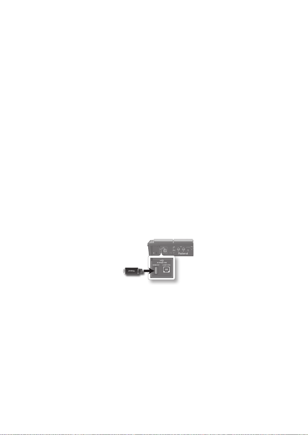
76
Maintenance
• For everyday cleaning wipe the unit with a
soft, dry cloth or one that has been slightly
dampened with water. To remove stubborn
dirt, use a cloth impregnated with a mild,
non-abrasive detergent. Afterwards, be sure
to wipe the unit thoroughly with a soft, dry
cloth.
• Never use benzine, thinners, alcohol or
solvents of any kind, to avoid the possibility
of discoloration and/or deformation.
Repairs and Data
• Please be aware that all data contained
in the unit’s memory may be lost when
the unit is sent for repairs. Important data
should always be backed up USB ash drives,
computer, or written down on paper (when
possible). During repairs, due care is taken
to avoid the loss of data. However, in certain
cases (such as when circuitry related to
memory itself is out of order), we regret that
it may not be possible to restore the data,
and Roland assumes no liability concerning
such loss of data.
Additional Precautions
• Please be aware that the contents of
memory can be irretrievably lost as a
result of a malfunction, or the improper
operation of the unit. To protect yourself
against the risk of loosing important data,
we recommend that you periodically save
a backup copy of important data you have
stored in the unit’s memory on USB ash
drives, or a computer.
• Unfortunately, it may be impossible to
restore the contents of data that was stored
in the unit’s memory or USB ash drives once
it has been lost. Roland Corporation assumes
no liability concerning such loss of data.
• Use a reasonable amount of care when using
the unit’s buttons, sliders, or other controls;
and when using its jacks and connectors.
Rough handling can lead to malfunctions.
• Never strike or apply strong pressure to the
display.
• When connecting / disconnecting all cables,
grasp the connector itself—never pull on the
cable. This way you will avoid causing shorts,
or damage to the cable’s internal elements.
• To avoid disturbing your neighbors, try to
keep the unit’s volume at reasonable levels.
You may prefer to use headphones, so you
do not need to be concerned about those
around you.
• This instrument is designed to minimize
the extraneous sounds produced when it’s
played. However, since sound vibrations
can be transmitted through oors and walls
to a greater degree than expected, take
care not to allow these sounds to become
a nuisance to neighbors, especially when
using headphones.
• When you need to transport the unit,
package it in the box (including padding)
that it came in, if possible. Otherwise, you
will need to use equivalent packaging
materials.
• Some connection cables contain resistors.
Do not use cables that incorporate resistors
for connecting to this unit. The use of such
cables can cause the sound level to be
extremely low, or impossible to hear. For
information on cable specications, contact
the manufacturer of the cable.
• The explanations in this manual include
illustrations that depict what should typically
be shown by the display. Note, however,
that your unit may incorporate a newer,
enhanced version of the system (e.g.,
includes newer sounds), so what you actually
see in the display may not always match
what appears in the manual.
• The rubber portion of the striking surface is
treated with a preservative to maintain its
performance. With the passage of time, this
preservative may appear on the surface as
a white stain, or reveal how the pads were
struck during product testing. This does not
aect the performance or functionality of
the product, and you may continue using it
with condence.
• Continuous playing may cause dis-coloration
of the pad, but this will not aect the Pad’s
function.
Before Using USB Flash Drives
• Carefully insert the USB ash drives all the
way in—until it is rmly in place.
USB ash drive
• Never touch the terminals of the USB ash
drives. Also, avoid getting the terminals dirty.
• USB ash drives are constructed using
precision components; handle the cards
carefully, paying particular note to the
following.
• To prevent damage to the cards from static
electricity, be sure to discharge any static
electricity from your own body before
handling the cards.
• Do not touch or allow metal to come into
contact with the contact portion of the
cards.
• Do not bend, drop, or subject cards to
strong shock or vibration.
• Do not keep cards in direct sunlight, in
closed vehicles, or other such locations.
• Do not allow cards to become wet.
• Do not disassemble or modify the cards.
Copyright
• Recording, duplication, distribution,
sale, lease, performance, or broadcast of
copyrighted material (musical works, visual
works, broadcasts, live performances, etc.)
belonging to a third party in part or in whole
without the permission of the copyright
owner is forbidden by law.
Do not use this product for purposes that
could infringe on a copyright held by a
third party. We assume no responsibility
whatsoever with regard to any infringements
of third-party copyrights arising through
your use of this product.
• The copyright of content in this product
(the sound waveform data, style data,
accompaniment patterns, phrase data,
audio loops and image data) is reserved by
Roland Corporation and/or Atelier Vision
Corporation.
• Purchasers of this product are permitted
to utilize said content for the creating,
performing, recording and distributing
original musical works.
• Purchasers of this product are NOT permitted
to extract said content in original or modied
form, for the purpose of distributing
recorded medium of said content or making
them available on a computer network.
• MMP (Moore Microprocessor Portfolio)
refers to a patent portfolio concerned with
microprocessor architecture, which was
developed by Technology Properties Limited
(TPL). Roland has licensed this technology
from the TPL Group.
• ASIO is a trademark of Steinberg Media
Technologies GmbH.
• This product contains eCROS integrated
software platform of eSOL Co.,Ltd. eCROS is a
trademark of eSOL Co., Ltd. in Japan.
• Company names and product names
appearing in this document are registered
trademarks or trademarks of their respective
owners.
77
This product complies with the requirements of EMC Directive 2004/108/EC.
For EU Countries
This Class B digital apparatus meets all requirements of the Canadian Interference-Causing Equipment Regulations.
Cet appareil numérique de la classe B respecte toutes les exigences du Règlement sur le matériel brouilleur du Canada.
NOTICE
AVIS
For the USA
FEDERAL COMMUNICATIONS COMMISSION
RADIO FREQUENCY INTERFERENCE STATEMENT
This equipment has been tested and found to comply with the limits for a Class B digital device, pursuant to Part 15 of the
FCC Rules. These limits are designed to provide reasonable protection against harmful interference in a residential
installation. This equipment generates, uses, and can radiate radio frequency energy and, if not installed and used in
accordance with the instructions, may cause harmful interference to radio communications. However, there is no guarantee
that interference will not occur in a particular installation. If this equipment does cause harmful interference to radio or
television reception, which can be determined by turning the equipment off and on, the user is encouraged to try to correct the
interference by one or more of the following measures:
– Reorient or relocate the receiving antenna.
– Increase the separation between the equipment and receiver.
– Connect the equipment into an outlet on a circuit different from that to which the receiver is connected.
– Consult the dealer or an experienced radio/TV technician for help.
This device complies with Part 15 of the FCC Rules. Operation is subject to the following two conditions:
(1) this device may not cause harmful interference, and
(2) this device must accept any interference received, including interference that may cause undesired operation.
This equipment requires shielded interface cables in order to meet FCC class B limit.
Any unauthorized changes or modifications not expressly approved by the party responsible for compliance could void the user’s
authority to operate the equipment.
For Canada
WARNING
This product contains chemicals known to cause cancer, birth defects and other reproductive harm, including lead.
For C.A. US
(
Proposition 65
)
For the USA
DECLARATION OF CONFORMITY
Compliance Information Statement
Model Name :
Type of Equipment :
Responsible Party :
Address :
Telephone :
SPD-SX
Electronic Drum
Roland Corporation U.S.
5100 S. Eastern Avenue Los Angeles, CA 90040-2938
(323) 890-3700
IMPORTANT: THE WIRES IN THIS MAINS LEAD ARE COLOURED IN ACCORDANCE WITH THE FOLLOWING CODE.
BLUE:
BROWN:
As the colours of the wires in the mains lead of this apparatus may not correspond with the coloured markings identifying
the terminals in your plug, proceed as follows:
The wire which is coloured BLUE must be connected to the terminal which is marked with the letter N or coloured BLACK.
The wire which is coloured BROWN must be connected to the terminal which is marked with the letter L or coloured RED.
Under no circumstances must either of the above wires be connected to the earth terminal of a three pin plug.
NEUTRAL
LIVE
For the U.K.
78
For China
For EU Countries

Information
When you need repair service, call your nearest Roland Service Center or authorized Roland
distributor in your country as shown below.
AFRICA
EGYPT
Al Fanny Trading O ce
9, EBN Hagar Al Askalany Street,
ARD E1 Golf, Heliopolis,
Cairo 11341, EGYPT
TEL: (022)-417-1828
REUNION
MARCEL FO-YAM Sarl
25 Rue Jules Hermann,
Chaudron - BP79 97 491
Ste Clotilde Cedex,
REUNION ISLAND
TEL: (0262) 218-429
SOUTH AFRICA
T.O.M.S. Sound & Music (Pty)Ltd.
2 ASTRON ROAD DENVER
JOHANNESBURG ZA 2195,
SOUTH AFRICA
TEL: (011) 417 3400
Paul Bothner(PTY)Ltd.
Royal Cape Park, Unit 24
Londonderry Road, Ottery 7800
Cape Town, SOUTH AFRICA
TEL: (021) 799 4900
ASIA
CHINA
Roland Shanghai Electronics
Co.,Ltd.
5F. No.1500 Pingliang Road
Shanghai 200090, CHINA
TEL: (021) 5580-0800
Roland Shanghai Electronics
Co.,Ltd. (BEIJING OFFICE)
3F, Soluxe Fortune Building
63 West Dawang Road, Chaoyang
District, Beijing, CHINA
TEL: (010) 5960-2565
HONG KONG
Tom Lee Music
11/F Silvercord Tower 1
30 Canton Rd
Tsimshatsui, Kowloon,
HONG KONG
TEL: 852-2737-7688
Parsons Music Ltd.
8th Floor, Railway Plaza, 39
Chatham Road South, T.S.T,
Kowloon, HONG KONG
TEL: 852-2333-1863
INDIA
Rivera Digitec (India) Pvt. Ltd.
411, Nirman Kendra Mahalaxmi
Flats Compound O . Dr. Edwin
Moses Road, Mumbai-400011,
INDIA
TEL: (022) 2493 9051
INDONESIA
PT. Citra Intirama
Ruko Garden Shopping Arcade
Unit 8 CR, Podomoro City
Jl.Letjend. S.Parman Kav.28
Jakarta Barat 11470, INDONESIA
TEL: (021) 5698-5519/5520
KOREA
Cosmos Corporation
1461-9, Seocho-Dong,
Seocho Ku, Seoul, KOREA
TEL: (02) 3486-8855
MALAYSIA/
SINGAPORE
Roland Asia Paci c Sdn. Bhd.
45-1, Block C2, Jalan PJU 1/39,
Dataran Prima, 47301 Petaling
Jaya, Selangor, MALAYSIA
TEL: (03) 7805-3263
PHILIPPINES
G.A. Yupangco & Co. Inc.
339 Gil J. Puyat Avenue
Makati, Metro Manila 1200,
PHILIPPINES
TEL: (02) 899 9801
TAI WAN
ROLAND TAIWAN ENTERPRISE
CO., LTD.
9F-5, No. 112 Chung Shan
North Road Sec. 2 Taipei 104,
TAIWAN R.O.C.
TEL: (02) 2561 3339
THAILAND
Theera Music Co. , Ltd.
100-108 Soi Verng Nakornkasem,
New Road,Sumpantawong,
Bangkok 10100, THAILAND
TEL: (02) 224-8821
VIET NAM
VIET THUONG CORPORATION
386 CACH MANG THANG TAM ST.
DIST.3, HO CHI MINH CITY,
VIET NAM
TEL: (08) 9316540
OCEANIA
AUSTRALIA/
NEW ZEALAND
Roland Corporation
Australia Pty.,Ltd.
38 Campbell Avenue
Dee Why West. NSW 2099,
AUSTRALIA
For Australia
TEL: (02) 9982 8266
For New Zealand
TEL: (09) 3098 715
CENTRAL/LATIN
AMERICA
ARGENTINA
Instrumentos Musicales S.A.
Av.Santa Fe 2055
(1123) Buenos Aires, ARGENTINA
TEL: (011) 4508-2700
BARBADOS
A&B Music Supplies LTD
12 Webster Industrial Park
Wildey, St.Michael, BARBADOS
TEL: (246) 430-1100
BRAZIL
Roland Brasil Ltda.
Rua San Jose, 211
Parque Industrial San Jose
Cotia - Sao Paulo - SP, BRAZIL
TEL: (011) 4615 5666
CHILE
Comercial Fancy II S.A.
Rut.: 96.919.420-1
Nataniel Cox #739, 4th Floor
Santiago - Centro, CHILE
TEL: (02) 688-9540
COLOMBIA
Centro Musical Ltda.
Cra 43 B No 25 A 41 Bododega 9
Medellin, COLOMBIA
TEL: (574) 3812529
COSTA RICA
JUAN Bansbach Instrumentos
Musicales
Ave.1. Calle 11, Apartado 10237,
San Jose, COSTA RICA
TEL: 258-0211
CURACAO
Zeelandia Music Center Inc.
Orionweg 30
Curacao, Netherland Antilles
TEL: (305) 5926866
DOMINICAN REPUBLIC
Instrumentos Fernando Giraldez
Calle Proyecto Central No.3
Ens.La Esperilla
Santo Domingo,
DOMINICAN REPUBLIC
TEL: (809) 683 0305
ECUADOR
Mas Musika
Rumichaca 822 y Zaruma
Guayaquil - ECUADOR
TEL: (593-4) 2302364
EL SALVADOR
OMNI MUSIC
75 Avenida Norte y Final Alameda
Juan Pablo II,
Edi cio No.4010 San Salvador,
EL SALVADOR
TEL: 262-0788
GUATEMALA
Casa Instrumental
Calzada Roosevelt 34-01,zona 11
Ciudad de Guatemala,
GUATEMALA
TEL: (502) 599-2888
HONDURAS
Almacen Pajaro Azul S.A. de C.V.
BO.Paz Barahona
3 Ave.11 Calle S.O
San Pedro Sula, HONDURAS
TEL: (504) 553-2029
MARTINIQUE
Musique & Son
Z.I.Les Mangle
97232 Le Lamentin,
MARTINIQUE F.W.I.
TEL: 596 596 426860
Gigamusic SARL
10 Rte De La Folie
97200 Fort De France
MARTINIQUE F.W.I.
TEL: 596 596 715222
MEXICO
Casa Veerkamp, s.a. de c.v.
Av. Toluca No. 323, Col. Olivar
de los Padres 01780 Mexico D.F.,
MEXICO
TEL: (55) 5668-6699
NICARAGUA
Bansbach Instrumentos
Musicales Nicaragua
Altamira D'Este Calle Principal
de la Farmacia 5ta.Avenida
1 Cuadra al Lago.#503
Managua, NICARAGUA
TEL: (505) 277-2557
PANAMA
SUPRO MUNDIAL, S.A.
Boulevard Andrews, Albrook,
Panama City, REP. DE PANAMA
TEL: 315-0101
PARAGUAY
Distribuidora De Instrumentos
Musicales
J.E. Olear y ESQ. Manduvira
Asuncion, PARAGUAY
TEL: (595) 21 492147
PERU
Audionet
Distribuciones Musicales SAC
Juan Fanning 530
Mira ores
Lima - PERU
TEL: (511) 4461388
TRINIDAD
AMR Ltd
Ground Floor
Maritime Plaza
Barataria TRINIDAD W.I.
TEL: (868) 638 6385
URUGUAY
Todo Musica S.A.
Francisco Acuna de Figueroa
1771
C.P.: 11.800
Montevideo, URUGUAY
TEL: (02) 924-2335
VENEZUELA
Instrumentos Musicales
Allegro,C.A.
Av.las industrias edf.Guitar import
#7 zona Industrial de Turumo
Caracas, VENEZUELA
TEL: (212) 244-1122
EUROPE
BELGIUM/FRANCE/
HOLLAND/
LUXEMBOURG
Roland Central Europe N.V.
Houtstraat 3, B-2260, Oevel
(Westerlo) BELGIUM
TEL: (014) 575811
CROATIA
ART-CENTAR
Degenova 3.
HR - 10000 Zagreb, CROATIA
TEL: (1) 466 8493
CZECH REP.
CZECH REPUBLIC DISTRIBUTOR
s.r.o
Voctárova 247/16
180 00 Praha 8, CZECH REP.
TEL: (2) 830 20270
DENMARK
Roland Scandinavia A/S
Skagerrakvej 7 Postbox 880
DK-2100 Copenhagen,
DENMARK
TEL: 3916 6200
FINLAND
Roland Scandinavia As, Filial
Finland
Vanha Nurmijarventie 62
01670 Vantaa, FINLAND
TEL: (0) 9 68 24 020
GERMANY/AUSTRIA
Roland Elektronische
Musikinstrumente HmbH.
Oststrasse 96, 22844 Norderstedt,
GERMANY
TEL: (040) 52 60090
GREECE/CYPRUS
STOLLAS S.A.
Music Sound Light
155, New National Road
Patras 26442, GREECE
TEL: 2610 435400
HUNGARY
Roland East Europe Ltd.
2045. Törökbálint, FSD Park 3. ép.,
HUNGARY
TEL: (23) 511011
IRELAND
Roland Ireland
E2 Calmount Park, Calmount
Avenue, Dublin 12,
Republic of IRELAND
TEL: (01) 4294444
ITALY
Roland Italy S. p. A.
Viale delle Industrie 8,
20020 Arese, Milano, ITALY
TEL: (02) 937-78300
NORWAY
Roland Scandinavia Avd.
Kontor Norge
Lilleakerveien 2 Postboks 95
Lilleaker N-0216 Oslo,
NORWAY
TEL: 2273 0074
POLAND
ROLAND POLSKA SP. Z O.O.
ul. Kty Grodziskie 16B
03-289 Warszawa, POLAND
TEL: (022) 678 9512
PORTUGAL
Roland Systems Group EMEA, S.L.
Branch O ce Porto
Edifício Tower Plaza
Rotunda Eng. Edgar Cardoso
23, 9ºG
4400-676 Vila Nova de Gaia,
PORTUGAL
TEL: (+351) 22 608 00 60
ROMANIA
FBS LINES
Piata Libertatii 1,
535500 Gheorgheni, ROMANIA
TEL: (266) 364 609
RUSSIA
Roland Music LLC
Dorozhnaya ul.3,korp.6
117 545 Moscow, RUSSIA
TEL: (495) 981-4967
SERBIA
Music AP Ltd.
Sutjeska br. 5 XS - 24413 Palic,
SERBIA
TEL: (024) 539 395
SLOVAKIA
DAN Acoustic s.r.o.
Povazská 18.
SK - 940 01 Nové Zámky,
SLOVAKIA
TEL: (035) 6424 330
SPAIN
Roland Systems Group EMEA, S.L.
Paseo García Faria, 33-35
08005 Barcelona, SPAIN
TEL: 93 493 91 00
SWEDEN
Roland Scandinavia A/S
SWEDISH SALES OFFICE
Mårbackagatan 31, 4 tr.
SE-123 43 Farsta, SWEDEN
TEL: (0) 8 683 04 30
SWITZERLAND
Roland (Switzerland) AG
Landstrasse 5, Postfach,
CH-4452 Itingen, SWITZERLAND
TEL: (061) 975-9987
UKRAINE
EURHYTHMICS Ltd.
P.O.Box: 37-a.
Nedecey Str. 30
UA - 89600 Mukachevo, UKRAINE
TEL: (03131) 414-40
UNITED KINGDOM
Roland (U.K.) Ltd.
Atlantic Close, SWANSEA SA7 9FJ,
UNITED KINGDOM
TEL: (01792) 702701
MIDDLE EAST
BAHRAIN
Moon Stores
No.1231&1249 Rumaytha
Building Road 3931,
Manama 339, BAHRAIN
TEL: 17 813 942
IRAN
MOCO INC.
Jadeh Makhsous Karaj (K-9),
Nakhe Zarin Ave.
Jalal Street, Reza Alley No.4
Tehran 1389716791, IRAN
TEL: (021)-44545370-5
ISRAEL
Halilit P. Greenspoon & Sons
Ltd.
8 Retzif Ha'alia Hashnia St.
Tel-Aviv-Yafo ISRAEL
TEL: (03) 6823666
JORDAN
MUSIC HOUSE CO. LTD.
FREDDY FOR MUSIC
P. O. Box 922846
Amman 11192, JORDAN
TEL: (06) 5692696
KUWAIT
EASA HUSAIN AL-YOUSIFI &
SONS CO.
Al-Yousi Service Center
P.O.Box 126 (Safat) 13002,
KUWAIT
TEL: 00 965 802929
LEBANON
Chahine S.A.L.
George Zeidan St., Chahine Bldg.,
Achra eh, P.O.Box: 16-5857
Beirut, LEBANON
TEL: (01) 20-1441
OMAN
TALENTZ CENTRE L.L.C.
Malatan House No.1
Al Noor Street, Ruwi
SULTANATE OF OMAN
TEL: 2478 3443
QATAR
AL-EMADI TRADING &
CONTRACTING CO.
P.O. Box 62, Doha, QATAR
TEL: 4423-554
SAUDI ARABIA
aDawliah Universal Electronics
APL
Behind Pizza Inn
Prince Turkey Street
aDawliah Building,
PO BOX 2154,
Alkhobar 31952,
SAUDI ARABIA
TEL: (03) 8643601
SYRIA
Technical Light & Sound Center
PO Box 13520 Bldg No.49
Khaled Abn Alwalid St.
Damascus, SYRIA
TEL: (011) 223-5384
TURKEY
ZUHAL DIS TICARET A.S.
Galip Dede Cad. No.33
Beyoglu, Istanbul, TURKEY
TEL: (0212) 249 85 10
U.A.E.
Zak Electronics & Musical
Instruments Co. L.L.C.
Zabeel Road, Al Sherooq Bldg.,
No. 14, Ground Floor, Dubai,
U.A.E.
TEL: (04) 3360715
NORTH AMERICA
CANADA
Roland Canada Ltd.
(Head O ce)
5480 Parkwood Way Richmond B.
C., V6V 2M4, CANADA
TEL: (604) 270 6626
Roland Canada Ltd.
(Toronto O ce)
170 Admiral Boulevard
Mississauga On L5T 2N6,
CANADA
TEL: (905) 362 9707
U. S. A.
Roland Corporation U.S.
5100 S. Eastern Avenue
Los Angeles, CA 90040-2938,
U. S. A.
TEL: (323) 890 3700
As of Feb. 1, 2011 (ROLAND)