
535iFR, 535iRXT, 535iRX
EN Operator's manual 2-33
Contents
Introduction..................................................................... 2
Safety..............................................................................4
Assembly...................................................................... 11
Operation...................................................................... 17
Maintenance................................................................. 24
Troubleshooting............................................................ 26
Transportation, storage and disposal........................... 27
Technical data.............................................................. 27
Accessories.................................................................. 29
Declaration of Conformity............................................. 30
Introduction
Product description
This product is a battery operated grass trimmer/
brushcutter with an electrical motor.
Work is constantly in progress to increase your safety
and efficiency during operation. Speak to your servicing
dealer for more information.
Intended use
Use the product with a saw blade, a grass blade or a
trimmer head to cut different types of vegetation. Do
not use the product for other tasks than grass trimming,
grass clearing and forestry clearing. Use a saw blade to
cut fibrous types of wood. Use a grass blade or trimmer
head to cut grass.
Note: National or local regulations can regulate the
use. Comply to given regulations.
Only use the product with accessories that are approved
by the manufacturer. Refer to
Accessories on page 29
.
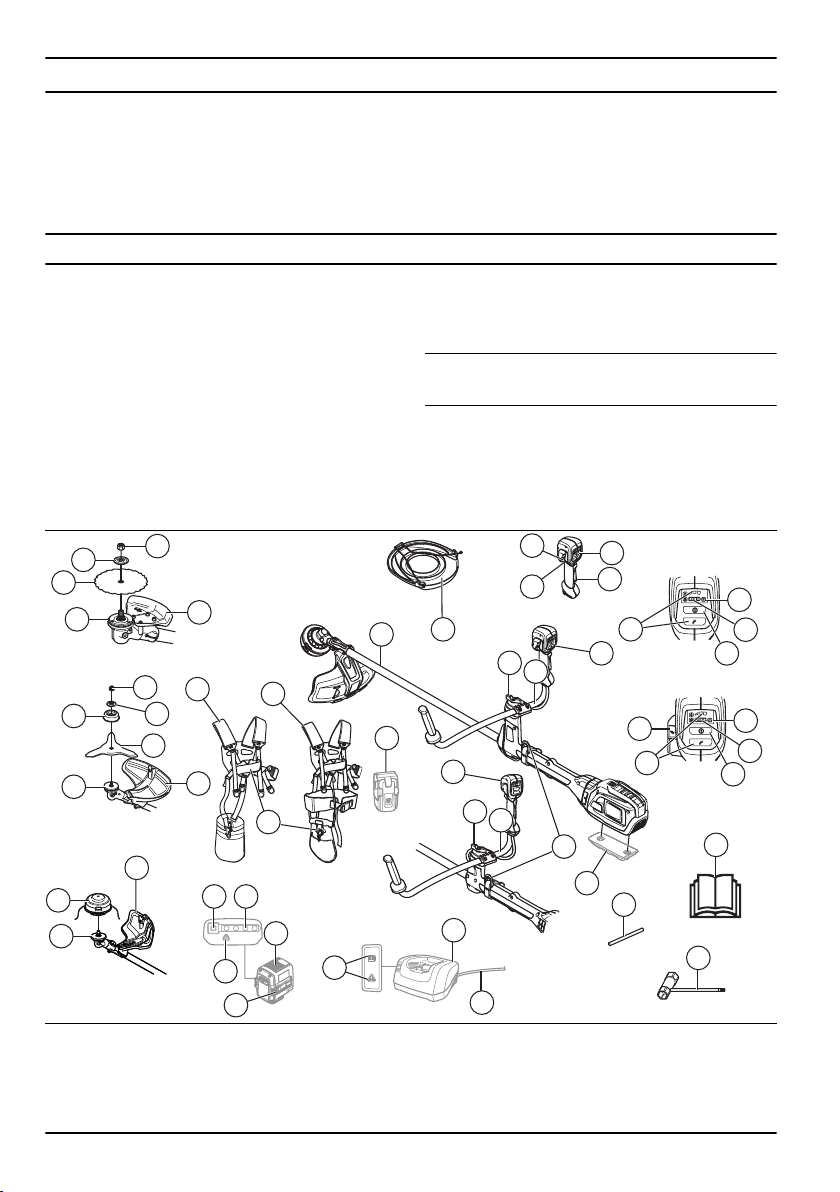
Product overview
7
4
5
iFR/iRX
iRXT
35
37
16
22
2324
13
21
30
27
26
32
2
28
28
18
25
28
1
30
29
31
6
3
20
19
36
15
17
33
13
9
10
8
11
11
12
12
13
34
14
14
10
6
7
23
15
23
29
1. Grass blade
2. Saw blade (535iFR)
3. Shaft
4. Balance 55 Harness (535iFR, 535iRX)
5. Balance XB Harness (535iRXT)
6. Knob
2 609 - 009 - 15.09.2022

7. Handlebar
8. Power trigger
9. Power trigger lockout
10. Add-on weight (accessory)
11. ErgoFeed button (535iRXT)
12. Handle
13. Warning indicator (LED)
14. Speed mode button
15. Start/Stop button
16. Charger
17. Charger cable
18. Power on and Warning indicator (LED)
19. Combination wrench
20. Locking pin
21. Battery release buttons
22. Battery
23. State of charge
24. Battery indicator button
25. Grass blade guard
26. Trimmer guard
27. Saw blade guard (535iFR)
28. Drive disc
29. Washer
30. Locknut
31. Support cup
32. Trimmer head
33. Transport guard
34. Harness support hook
35. Battery carrier (accessory)
36. Operator's manual
37. Quick-release mechanism
Symbols on the product
WARNING! This product can be
dangerous! Careless or incorrect use
can result in serious or fatal injury to
the operator or others. It is extremely
important that you read and understand
the contents of the operator's manual.
Please read the operator’s manual
carefully and make sure you understand
the instructions before the product is
used.
Use a protective helmet in locations where
objects can fall on you. Use approved
hearing protection. Use approved eye
protection.
/min
Maximum speed of the output shaft.
The product can cause objects to eject,
which can cause injury.
The product complies with the applicable
EU directives.
This product conforms to the applicable
UK regulations.
Keep a minimum distance of 15 m to
persons and animals during operation of
the product.
Risk of blade thrust if the cutting
equipment touches an object that it does
not immediately cut. The product can cut
off body parts. Keep a minimum of 15 m
distance to persons and animals during
operation of the product.
Use approved protective gloves.
Use heavy-duty slip-resistant boots.
Only use a flexible cutting wire. Do not
use metal cutting elements.
Protected against splashing water.
Noise emission to the environment label
as per EU (also including New South
Wales legislation) and UK directives
and regulations. The guaranteed sound
power level of the product is specified in
Technical data on page 27
and on the
label.
Symbols on the product or its packaging
indicate that this product cannot be
handled as domestic waste. This product
must be deposited at an appropriate
recycling facility.
609 - 009 - 15.09.2022 3
Direct current.
Keep all parts of your body away from the
hot surfaces.
If the product features
Bluetooth
®
wireless
technology. The
Bluetooth
®
symbol will be
marked on the product name label. Refer
to
Husqvarna Connect on page 17
.
yyyywwxxxxx The rating plate shows the serial
number. yyyy is the production year,
ww is the production week and xxxxx
is the sequential number.
Note: Other symbols/decals on the product refer to
certification requirements for other commercial areas.
Manufacturer
Husqvarna AB
Drottninggatan 2, SE-561 82 Huskvarna, Sweden, tel:
+46-36-146500
Product liability
As referred to in the product liability laws, we are not
liable for damages that our product causes if:
• the product is incorrectly repaired.
• the product is repaired with parts that are not
from the manufacturer or not approved by the
manufacturer.
• the product has an accessory that is not from the
manufacturer or not approved by the manufacturer.
• the product is not repaired at an approved service
center or by an approved authority.
Safety
Safety definitions
Warnings, cautions and notes are used to point out
specially important parts of the manual.
WARNING: Used if there is a risk of
injury or death for the operator or bystanders
if the instructions in the manual are not
obeyed.
CAUTION: Used if there is a risk of
damage to the product, other materials or
the adjacent area if the instructions in the
manual are not obeyed.
Note: Used to give more information that is necessary
in a given situation.
General power tool safety warnings
WARNING: Read all safety warnings,
instructions, illustrations and specifications
provided with this power tool. Failure to
follow all instructions listed below may result
in electric shock, fire and/or serious injury.
• Save all warnings and instructions for future
reference. The term "power tool" in the warnings
refers to your mains-operated (corded) power tool or
battery-operated (cordless) power tool.
Work area safety
• Keep work area clean and well lit. Cluttered or dark
areas invite accidents.
• Do not operate power tools in explosive
atmospheres, such as in the presence of flammable
liquids, gases or dust. Power tools create sparks
which may ignite the dust or fumes.
• Keep children and bystanders away while operating
a power tool. Distractions can cause you to lose
control.
Electrical safety
• Power tool plugs must match the outlet. Never
modify the plug in any way. Do not use any
adapter plugs with earthed (grounded) power tools.
Unmodified plugs and matching outlets will reduce
risk of electric shock.
• Avoid body contact with earthed or grounded
surfaces, such as pipes, radiators, ranges and
refrigerators. There is an increased risk of electric
shock if your body is earthed or grounded.
• Do not expose power tools to rain or wet conditions.
Water entering a power tool will increase the risk of
electric shock.
• Do not abuse the cord. Never use the cord for
carrying, pulling or unplugging the power tool. Keep
cord away from heat, oil, sharp edges or moving
parts. Damaged or entangled cords increase the risk
of electric shock.
• When operating a power tool outdoors, use an
extension cord suitable for outdoor use. Use of a
4
609 - 009 - 15.09.2022

cord suitable for outdoor use reduces the risk of
electric shock.
• If operating a power tool in a damp location is
unavoidable, use a residual current device (RCD)
protected supply. Use of a RCD reduces the risk of
electric shock.
Personal safety
• Stay alert, watch what you are doing and use
common sense when operating a power tool. Do not
use a power tool while you are tired or under the
influence of drugs, alcohol or medication. A moment
of inattention while operating power tools may result
in serious personal injury.
• Use personal protective equipment. Always wear
eye protection. Protective equipment such as dust
mask, non-skid safety shoes, hard hat or hearing
protection used for appropriate conditions will reduce
personal injuries.
• Prevent unintentional starting. Ensure the switch is
in the off-position before connecting to power source
and/or battery pack, picking up or carrying the tool.
Carrying power tools with your finger on the switch
or energising power tools that have the switch on
invites accidents.
• Remove any adjusting key or wrench before turning
the power tool on. A wrench or a key left attached
to a rotating part of the power tool may result in
personal injury.
• Do not overreach. Keep proper footing and balance
at all times. This enables better control of the power
tool in unexpected situations.
• Dress properly. Do not wear loose clothing or
jewellery. Keep your hair and clothing away from
moving parts. Loose clothes, jewellery or long hair
can be caught in moving parts.
• If devices are provided for the connection of dust
extraction and collection facilities, ensure these are
connected and properly used. Use of dust collection
can reduce dust-related hazards.
• Do not let familiarity gained from frequent use of
tools allow you to become complacent and ignore
tool safety principles. A careless action can cause
severe injury within a fraction of a second.
Power tool use and care
• Do not force the power tool. Use the correct power
tool for your application. The correct power tool will
do the job better and safer at the rate for which it
was designed.
• Do not use the power tool if the switch does not
turn it on and off. Any power tool that cannot be
controlled with the switch is dangerous and must be
repaired.
• Disconnect the plug from the power source and/or
remove the battery pack, if detachable, from the
power tool before making any adjustments, changing
accessories, or storing power tools. Such preventive
safety measures reduce the risk of starting the
power tool accidentally.
•
Store idle power tools out of the reach of children
and do not allow persons unfamiliar with the power
tool or these instructions to operate the power tool.
Power tools are dangerous in the hands of untrained
users.
• Maintain power tools and accessories. Check for
misalignment or binding of moving parts, breakage
of parts and any other condition that may affect the
power tool´s operation. If damaged, have the power
tool repaired before use. Many accidents are caused
by poorly maintained power tools.
• Keep cutting tools sharp and clean. Properly
maintained cutting tools with sharp cutting edges are
less likely to bind and are easier to control.
• Use the power tool, accessories and tool bits etc.
in accordance with these instructions, taking into
account the working conditions and the work to be
performed. Use of the power tool for operations
different from those intended could result in a
hazardous situation.
• Keep handles and grasping surfaces dry, clean
and free from oil and grease. Slippery handles and
grasping surfaces do not allow for safe handling and
control of the tool in unexpected situations.
Battery tool use and care
• Recharge only with the charger specified by the
manufacturer. A charger that is suitable for one type
of battery pack may create a risk of fire when used
with another battery pack.
• Use power tools only with specifically designated
battery packs. Use of any other battery packs may
create a risk of injury and fire.
• When battery pack is not in use, keep it away from
other metal objects, like paper clips, coins, keys,
nails, screws or other small metal objects, that can
make a connection from one terminal to another.
Shorting the battery terminals together may cause
burns or a fire.
• Under abusive conditions, liquid may be ejected from
the battery; avoid contact. If contact accidentally
occurs, flush with water. If liquid contacts eyes,
additionally seek medical help. Liquid ejected from
the battery may cause irritations or burns.
• Do not use a battery pack or tool that is damaged or
modified. Damaged or modified batteries may exhibit
unpredictable behaviour resulting in fire, explosion or
risk of injury.
• Do not expose a battery pack or tool to fire
or excessive temperature. Exposure to fire or
temperature above 130 °C may cause explosion.
• Follow all charging instructions and do not charge
the battery pack or tool outside the temperature
range specified in the instructions. Charging
improperly or at temperatures outside the specified
range may damage the battery and increase the risk
of fire.
• Remove the battery pack from the tool before
making adjustments, changing accessories, or
storing the tool.Such preventive safety measures
609 - 009 - 15.09.2022
5

reduce the risk of starting the battery tools
accidentally.
Service
• Have your power tool serviced by a qualified repair
person using only identical replacement parts. This
will ensure that the safety of the power tool is
maintained.
• Never service damaged battery packs. Service of
battery packs should only be performed by the
manufacturer or authorized service providers.
Other general safety information
• Deactivate the product before you move to another
area. Always remove the battery when passing the
product to another person.
• Never put the product down unless you have
deactivated it and removed the battery. Do not leave
the product unsupervised when it is switched on.
• The cutting tool does not stop immediately after the
product is turned off.
• The blade should be completely stopped once the
trigger switch has returned to the initial position.
• Before using the product and after any impact,
check for signs of wear or damage and repair as
necessary.
• If anything jams in the cutting attachment while
you operate the product, stop and deactivate the
product. Make sure that the cutting attachment stops
completely. Remove the battery before you clean,
inspect or repair the product and/or the cutting
equipment.
• Do a check of the product before use. Refer to,
Safety on page 4
and
Maintenance on page 24
. Do
not use a defective product. Do the safety checks,
maintenance and service instructions described in
this manual.
• Faulty cutting attachment can increase the risk of
accidents.
• Check the gear for dirt and cracks. Clean off grass
and leaves from the gear using a brush. Gloves
should be worn when necessary.
• Always ensure that ventilation openings are kept
clear of debris.
• Check that the trimmer head is completely attached
to the trimmer.
• All covers, guards and handles must be fitted before
starting.
• Check that the product is in perfect working order.
Check that all nuts and screws are tight.
• Check that the trimmer head and trimmer guard are
not damaged or cracked. Replace the trimmer head
or trimmer guard if it has been exposed to impact or
are cracked. Always use the recommended guard for
the cutting attachment you are using. See chapter on
Technical data.
• This product is a dangerous tool if you are not
careful or if you use the product incorrectly. This
product can cause serious injury or death to the
operator or others.
• This appliance is not intended for use by persons
(including children) with reduced physical, sensory
or mental capabilities, or lack of experience and
knowledge, unless they have been given supervision
or instruction concerning use of the appliance by a
person responsible for their safety. Children should
be supervised to ensure that they do not play with
the appliance.
• Never allow children to use or be in the vicinity of the
machine. Since the machine is easy to start, children
may be able to start it if they are not kept under
full surveillance. This can mean a risk of serious
personal injury. Therefore disconnect the battery
when the machine is not under close supervision.
• Never allow children or other persons not trained in
the use of the product and/or the battery to use or
service it.
• National or local regulations may regulate the use.
Comply to given regulations.
• Store the equipment in a lockable area so that it is
out of reach of children and unauthorized persons.
• The transport guard must always be used for storage
and transport.
• Keep hands and feet away from the cutting area
at all times and especially when switching on the
motor.
• Keep your hands and feet away from the cutting
attachment until it has stopped completely when the
product is deactivated.
• Do not remove the cut material, or let other persons
remove cut material, while the product is activated
or the cutting equipment rotates, as this can result in
serious injury.
• Keep in mind that it is you, the operator that is
responsible for not exposing people or their property
to accidents or hazards.
• Under no circumstances may the design of the
product be modified without the permission of the
manufacturer. Always use original accessories. Non-
authorized modifications and/or accessories can
result in serious personal injury or the death of
the operator or others. Your warranty may not
cover damage or liability caused by the use of non-
authorized accessories or replacement parts.
• The only accessories you can operate with this
product are the cutting attachments recommended
in the technical data chapter.
• Never use a product that has been modified in any
way from its original specification
• Never use a product that is faulty. Carry out the
safety checks, maintenance and service instructions
described in this manual. Some maintenance and
service measures must be carried out by trained
and qualified specialists. See instructions under the
Maintenance heading.
• Working in bad weather is tiring and often brings
added risk. Due to the added risk, it is not
6
609 - 009 - 15.09.2022
recommended to use the machine in very bad
weather, for instance in dense fog, heavy rain,
strong winds, intense cold, risk of lightning, etc
• Never work from a ladder, stool or any other raised
position that is not fully secured.
• Store Idle Appliances Indoors – When not in use,
appliances should be stored indoors
• It is not possible to cover every conceivable situation
you can face. Always exercise care and use your
common sense. Avoid all situations which you
consider to be beyond your capability. If you still feel
uncertain about operating procedures after reading
these instructions, you should consult an expert
before continuing.
• Ensure that no people or animals come closer than
15 meters while you work. When several operators
are working in the same area the safety distance
should be at least 15 metres. Otherwise there is
a risk of serious personal injury. Stop the product
immediately if anyone approaches. Never swing the
product around without first checking behind you to
make sure that no one is within the safety zone.
• If anything jams in the cutting attachment while
you operate the product, stop and deactivate the
product. Make sure that the cutting attachment stops
completely. Remove the battery before you clean,
inspect or repair the product and/or the cutting
equipment.
• Ensure that people, animals or other things can
not affect your control of the product or that they
do not come in contact with the cutting attachment
or loose objects that are thrown out by the cutting
attachment. However, do not use the product unless
you are able to call for help in the event of an
accident.
• Make sure that you can move and stand safely.
Check the area around you for possible obstacles
(roots, rocks, branches, ditches, etcetera) in case
you have to move suddenly. Take great care when
you work on sloping ground.
• Walk, never run.
• Inspect the working area. Remove all loose objects,
such as stones, broken glass, nails, steel wire, string
etc. that could be thrown out or become wrapped
around the cutter or cutter guard.
• Watch out for stumps of branches that can be thrown
out when you cut. Do not cut to close to the ground
where stones and other objects can be thrown out.
• Make sure that no clothes or parts of the body
come in contact with the cutting attachment when
the product is activated. Keep the product below
waist level.
• Watch out for thrown objects. Always wear approved
eye protection. Never lean over the cut-ting
attachment guard. Stones, rubbish, etc., can be
thrown up into the eyes which can cause blindness
or serious injury.
• Listen out for warning signals or shouts when
you wear hearing protection. Always remove your
hearing protection as soon as the product stops.
• If any unwanted vibrations occur, tap out new line to
give the line the correct length to stop the vibrations.
• If the product starts vibrating abnormally, stop the
product and remove the battery.
• Overexposure to vibration can lead to circulatory
damage or nerve damage in persons who have
poor circulation. Speak to your physician if you
experience symptoms of overexposure to vibration.
Such symptoms include numbness, loss of feeling,
tingling, pricking, pain, loss of strength, changes
in skin color or condition. These symptoms usually
show in the fingers, hands or wrists.
• Always hold the product with both hands. Hold the
product on the right side of your body.
Personal protective equipment
WARNING: Read the warning
instructions that follow before you use the
product.
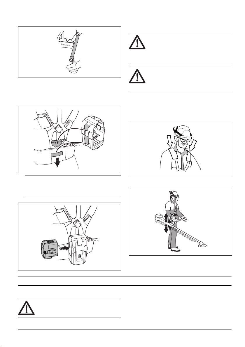
• Always use approved personal protective equipment
when you use the product. Personal protective
equipment cannot fully prevent injury but it
decreases the degree of injury if an accident does
occur. Let your dealer help you select the correct
equipment.
• Use a helmet if the trees in the work area have a
height of more than 2 m/6.5 ft.
• Use approved hearing protection.
• Always use approved protective googles that comply
with ANSI Z87.1 standard in the USA or EN 166 in
EU countries.Use visor for face protection. Visor is
not enough to protect the eyes.
+
• Use gloves when it is necessary, for example when
you attach, examine or clean the cutting equipment.
• Use protective boots with steel toe-cap and non-slip
soles.
• Use clothing made of a strong fabric. Always use
heavy, long pants and long sleeves. Do not use
loose clothing that can catch on twigs and branches.
Do not use jewelry, short pants or sandals. Do not
go with bare feet. Put your hair up safely above
shoulder level.
609 - 009 - 15.09.2022
7
• Keep first aid equipment near.
Safety devices on the product
WARNING: Read the warning
instructions that follow before you use the
product.
In this section the product’s safety features, its purpose
and how checks and maintenance should be carried
out to ensure that it operates correctly. See instructions
under the heading
Product overview on page 2
to find
where these parts are located on your product.
The life span of the product can be reduced and the risk
of accidents can increase if product maintenance is not
carried out correctly and if service and/or repairs are not
carried out professionally. If you need further information
please contact your nearest servicing dealer.
WARNING: Never use a product with
defective safety components. The product's
safety equipment must be inspected and
maintained as described in this section.
If your product fails any of these checks,
contact your service agent to get it repaired.
CAUTION: All servicing and repair work
on the machine requires special training.
This is especially true of the machine′s
safety equipment. If your machine fails
any of the checks described below you
must contact your service agent. When
you buy any of our products we guarantee
the availability of professional repairs and
service. If the retailer who sells your
machine is not a servicing dealer, ask him
for the address of your nearest service
agent.
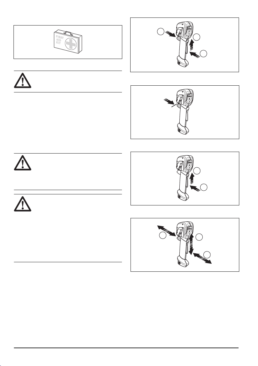
To do a check of the power trigger lockout
The power trigger lockout prevents accidental operation.
When you push the power trigger lockout forward (A)
and then press the power trigger lockout against the
handle (B), the power trigger (C) is released. When you
release the handle, the power trigger and the power
trigger lockout move back to their initial positions. This
movement is operated by independent springs.
C
A
B
1. Make sure that the power trigger is locked when the
lock is in its initial position.
2. Press the power trigger and make sure that it goes
back to its initial position when you release it.
A
B
3. Make sure that the power trigger and the lock moves
freely and that the return spring operates correctly.
C
A
B
4. Start the product, refer to
To start the product on
page 19
.
5. Apply full speed.
6. Release the power trigger and make sure that the
cutting attachment stops fully.
8
609 - 009 - 15.09.2022
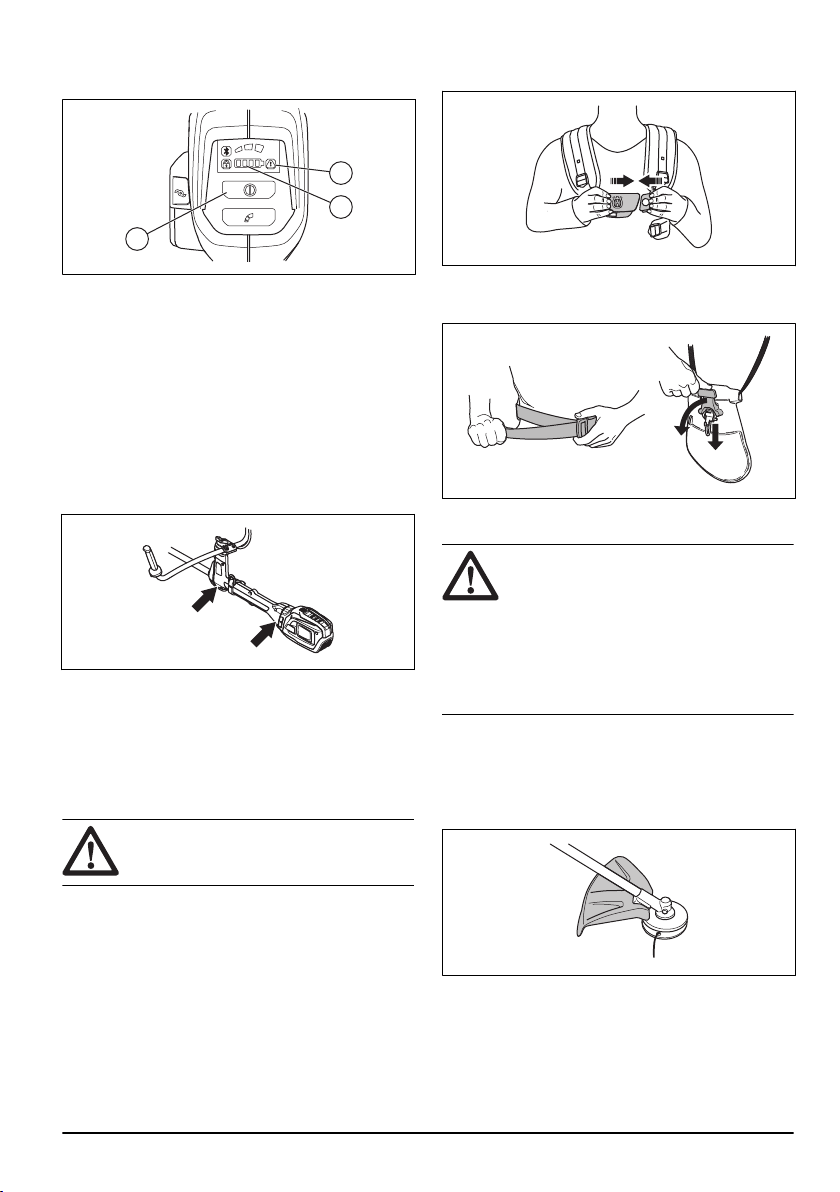
To do a check of the user interface
1. Push and hold the start/stop button (A).
A
C
B
a) The product is on when the LED (B) is on.
b) The product is off when the LED (B) is out.
2. If the warning indicator (C) comes on or flashes,
refer to
Troubleshooting on page 26
.
To do a check of the vibration damping system
(535iRXT, 535iRX)
The vibration damping system decreases vibration in
the handles to a minimum which makes the operation
easier. The vibration damping system of the product
decreases the vibration from the cutting attachment to
the handlebar and handles.
1. Stop the product.
2. Do a visual check for deformation and damage, for
example, cracks.
3. Push the anti-vibration suspension lightly and make
sure that it can move slightly in all directions.
To do a check of the quick release function
WARNING: Do not use a harness with
a defective quick release function.
1. Stop the motor.
2. Do a visual check for damage for example, cracks.
3. Release and attach the quick release mechanism to
make sure that it operates correctly.
4. If the harness has a hip pad and a hip strap,
make sure that the quick release function operates
correctly.
To do a check of the cutting attachment guard
WARNING: Do not use a cutting
attachment without an approved and
correctly attached cutting attachment guard.
Always use the recommended cutting
attachment guard for the cutting attachment
that you use, see
Accessories on page 29
.
If an incorrect or faulty cutting attachment
guard is attached this can cause serious
personal injury.
The cutting attachment guard stops objects that ejects in
the direction of the operator. It also prevents injuries that
occur if you touch the cutting attachment.
1. Stop the product and remove the battery.
2. Do a visual check for damages, for example cracks.
3. Replace the cutting attachment guard if it is
damaged.
609 - 009 - 15.09.2022
9
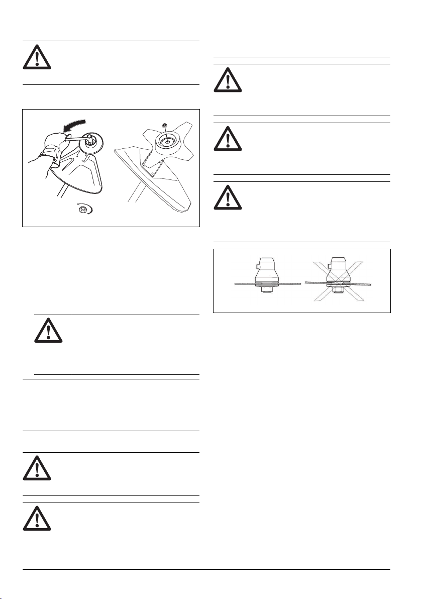
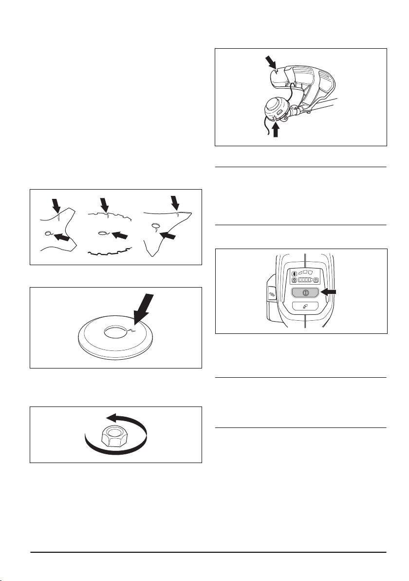
To attach and remove the locknut
WARNING: Stop the product and
remove the battery, use protective gloves
and be careful around the sharp edges of
the cutting attachment.
A locknut is used to attach some types of cutting
attachments. The locknut has a left thread.
• To attach, tighten the locknut in the opposite
direction to the direction of rotation of the cutting
attachment.
• To remove the locknut, undo the lock nut in the
same direction as the cutting attachment rotates.
• To loose and tighten the locknut, use a socket
spanner with a long shaft. The arrow in the picture
shows the area where you should operate the socket
spanner.
WARNING:
When you loose and
tighten the locknut there is a risk of
injury from the teeth of the saw blade.
You should therefore always ensure that
your hand is shielded by the blade guard
when you do this.
Note: Make sure that you can not turn the locknut by
hand. Replace the nut if the nylon lining does not have
a resistance of a minimum of 1.5 Nm. The nut should
be replaced after it has been put on approximately 10
times.
Cutting attachment
WARNING:
Remove the battery and
make sure that the cutting attachment stops
completely before you work on any part of
the cutting attachment.
WARNING: Use correct cutting
attachment. Only use the cutting attachment
with the guards we recommend, refer
to
Accessories on page 29
. Make sure
that the cutting attachment is sharpened
correctly. A cutting attachment that is not
sharpened correctly increases the risk of
blade thrust.
WARNING: An incorrectly sharpened
or damaged blade increases the risk of
accidents. Keep the teeth of the blade
correctly sharpened. Follow the instructions
and use the recommended file gauge.
WARNING: A coasting blade can
cause injury while it continues to spin after
the switch has been released. Need to
maintain proper control until the blade has
completely stopped rotating.
CAUTION: An incorrectly set saw
blade increases the risk of jamming and
blade thrust. This can damage the saw
blade. Keep the correct setting on the saw
blade. Follow the instructions and use the
recommended setting tool.
Wear protective gloves when the cutting attachment is
handled.
• Use the saw blade to cut fibrous types of wood.
• Use the blades and grass knives to cut coarse grass.
• Use the trimmer head to trim grass.
• Check the cutting attachment for damage or cracks.
Replace a damaged cutting attachment.
Trimmer head
• Always use the correct trimmer head, cutting
attachments and always use the recommended
trimmer line. Refer to
Accessories on page 29
and
the assembly in the end of the Manual.
• Make sure that the cutter on the trimmer guard is not
damaged.
• Make sure that the trimmer line is wound tightly
and equally around the drum to prevent unusual
vibrations from the product. Different cord lengths
can result in vibrations that are not necessary. Tap
the trimmer head to get correct length on the cord.
To increase the life of the cord it can be soaked in water
for 2 days or more before assembly. This will make the
cord more resistant.
10
609 - 009 - 15.09.2022
Saw blade and grass blade
• Use correctly sharpened blades. An incorrectly
sharpened or damaged blade increases the risk of
injury.
• Use correctly set blades. Correct blade set is 1 mm.
An incorrectly set blade increases the risk of injury
and damage.
• To sharpen and set the blade correctly, refer to the
instructions that come with the blade.
Safety instructions for assembly
WARNING: Read, understand and
obey these instructions carefully before you
use the product.
• Remove the battery from the product before you
assemble the product.
• Use approved protective gloves.
• When you use a saw blade or a grass blade, make
sure that the correct handlebar, the blade guard and
the harness are attached to the product.
• A defective or incorrect guard can cause injury. Do
not use a cutting attachment that does not have an
approved guard attached.
• Make sure that you assemble the cover and shaft
correct before you start the product.
• The drive disc and support flange must engage
correctly in the centre hole of the cutting attachment.
A cutting attachment that is attached incorrectly can
cause injury or death.
• To operate the product safely and prevent injury
to the operator or other persons, the product must
always be attached correctly to the harness.
Safety instructions for maintenance
WARNING: Read the warning
instructions that follow before you do
maintenance on the product.
• Remove the battery before you do maintenance,
other checks or assemble the product.
• The operator must only do the maintenance and
servicing shown in this operator's manual. Turn to
your servicing dealer for maintenance and servicing
of a larger extension.
• Do not clean the battery or the battery charger with
water. Strong detergent can cause damage to the
plastic.
• If you do not do maintenance, it decreases the
life cycle of the product and increases the risk of
accidents.
• Special training is necessary for all servicing and
repair work, especially for the safety devices on the
product. If not all checks in this operator's manual
are approved after you have done maintenance, turn
to your servicing dealer. We guarantee that there are
professional repairs and servicing available for your
product.
• Keep the teeth of the blade correctly sharpened.
Obey our recommendations. Also refer to the
instructions on the blade package.
• Only use original spare parts.
• Always use heavy duty gloves when you repair the
cutting attachment. The blades are very sharp and
can easily cause injuries.
Assembly
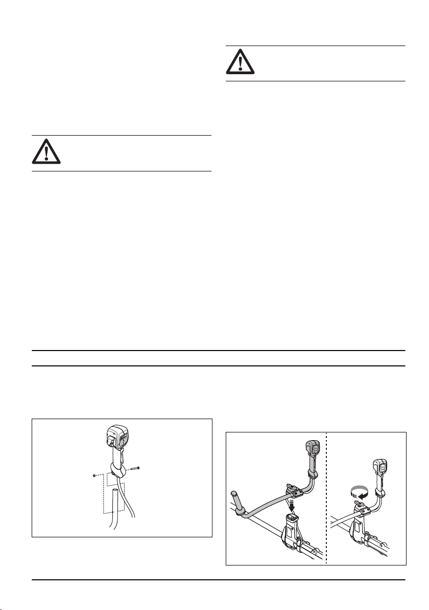
To attach the handle
1. Remove the nut and screw from the bottom of the
handle.
2. Attach the handle onto the handlebar.
3. Align the screw hole in the handle with the screw
hole in the handlebar.
4. Put the screw into the screw hole at the bottom of
the handle and through the handlebar.
5. Attach the nut on the screw and tighten the nut.
To assemble the handlebar
1. Put the handlebar into the bracket.
609 - 009 - 15.09.2022 11
2. Attach the knob but do not tighten fully.
3. Adjust the handlebar to put the product in a good
operation position.
4. Tighten the knob fully.
To put the handlebar in transport
position
1. Loosen the knob.
2. Turn the handlebar until it is parallel to the shaft.
3. Turn the handlebar around the shaft.
4. Tighten the knob.
To assemble the cutting equipment
The cutting equipment includes a cutting attachment and
a cutting attachment guard.
WARNING:
Stop the product and
remove the battery. Use protective gloves.
WARNING: Always use the cutting
attachment guard that is recommended for
the cutting attachment. See
Accessories on
page 29
.
WARNING: An incorrectly attached
cutting attachment can result in injury or
death.
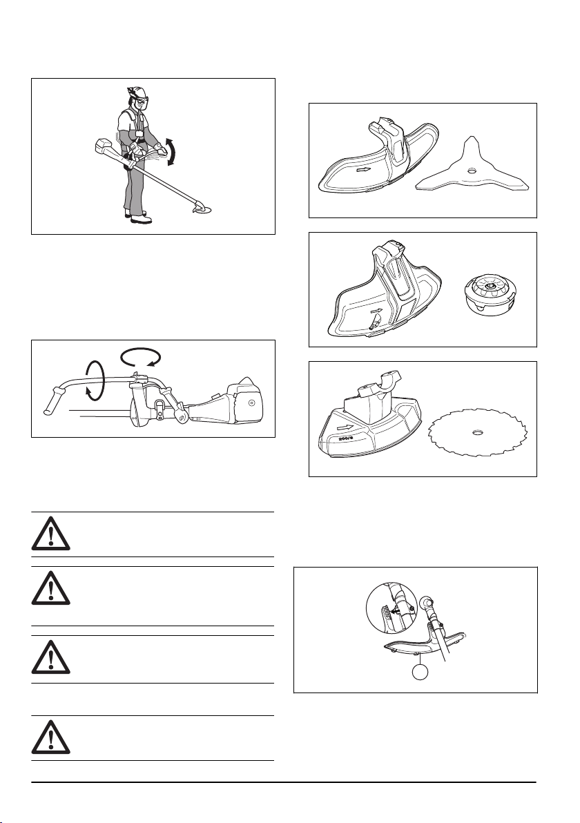
Cutting equipment and guards
WARNING:
Stop the product and
remove the battery. Use protective gloves.
The product have different cutting attachment guards
for the cutting equipment that can be used. Make sure
that you use the correct cutting attachment guard for the
cutting equipment. Refer to
Accessories on page 29
.
• Grass blade guard and grass blade.
• Trimmer guard and trimmer head.
• Saw blade guard and saw blade.
Assembly of the grass blade guard and the
grass blade
To attach the grass blade guard
• Put the grass blade guard (A) onto the shaft and
tighten the bolt.
A
12
609 - 009 - 15.09.2022
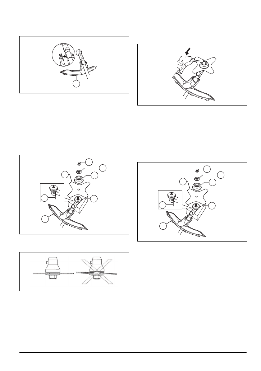
To remove the grass blade guard
• Remove the bolt and remove the grass blade guard
(A) from the shaft.
A
To attach the grass blade
1. Put the gear of the product on a flat surface to make
sure that the blade is assembled correctly.
2. Turn the output shaft to align one of the holes in
the drive disc (B) with the related hole in the gear
housing.
3. Put the locking pin (C) in the hole to lock the shaft.
4. Put the grass blade (D), the support cup (E) and the
support flange (F) on the output shaft.
G
F
D
B
C
A
E
5. Make sure that the drive disc and support flange
engages correctly in the center hole of the grass
blade.
6. Attach the nut (G).
7. Tighten the nut with the socket wrench. Hold the
shaft of the socket wrench near the blade guard.
Tighten in the opposite direction to how the cutting
attachment rotates. Tighten it to a torque of 35-50
Nm.
To remove the grass blade
1. Put the gear of the product on a flat surface to make
sure that the blade is removed correctly.
2. Put the locking pin (C) into the hole on the shaft to
lock the shaft.
3. Remove the nut (G).
4. Remove the support flange (F), the support cup (E)
and the grass blade (D) from the output shaft.
G
F
D
B
C
A
E
609 - 009 - 15.09.2022 13
Assembly of the trimmer guard and the
trimmer head
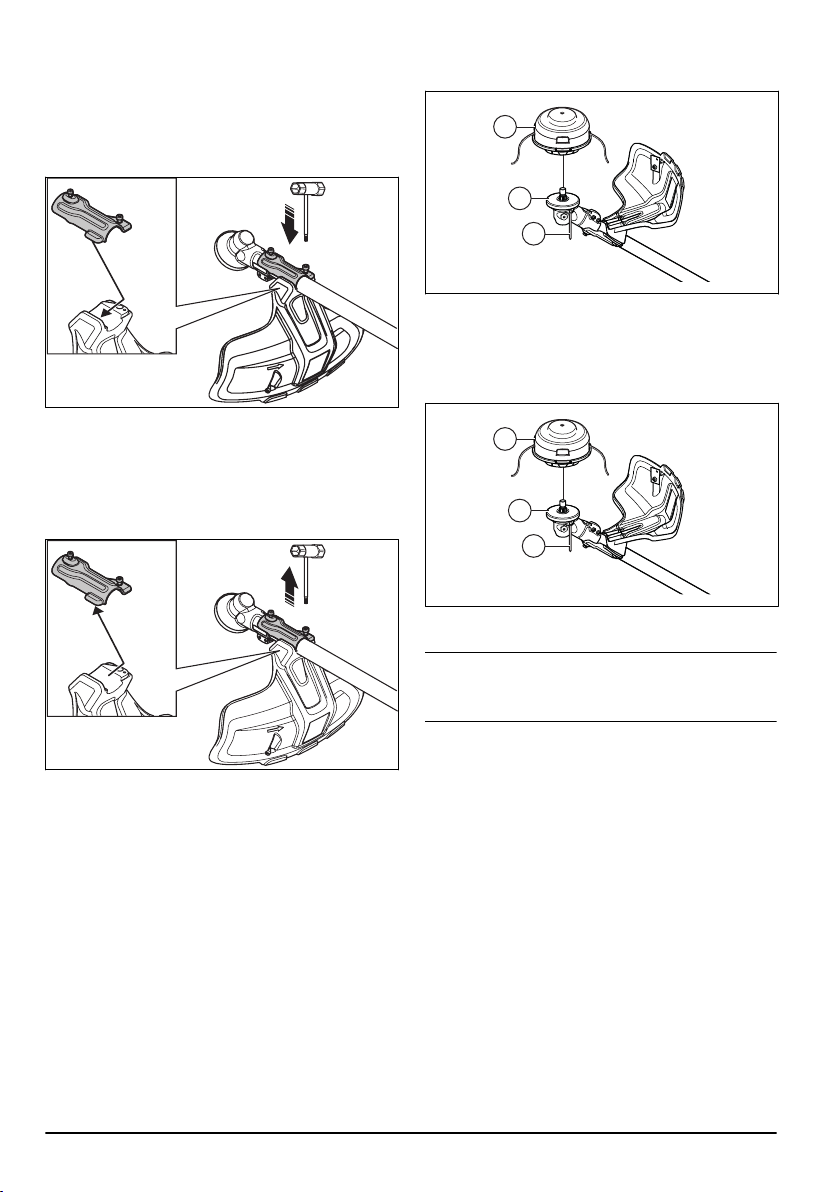
To attach the trimmer guard
1. Attach the plate holder to the gear with the smallest
bolt. Tighten the bolt.
2. Attach the trimmer guard to the plate holder.
3. Attach the biggest bolt and tighten it.
To remove the trimmer guard
1. Remove the bolts.
2. Remove the trimmer guard.
To attach the trimmer head T35 (535iFR, 535iRX)
1. Put the drive disc (B) on the output shaft.
2. Turn the output shaft to align one of the holes in the
drive disc with the related hole in the gear housing.
3. Put the locking pin (C) in the hole to lock the shaft.
4. Turn the trimmer head (H) counterclockwise to
attach.
H
B
C
To remove the trimmer head T35 (535iFR, 535iRX)
1. Put the locking pin (C) in the hole to lock the shaft.
2. Turn the trimmer head (H) clockwise to remove it.
3. Remove the drive disc (B) from the output shaft.
H
B
C
To attach the trimmer head E35B (535iRXT)
Note:
To increase the life of the cord it can be soaked
in water for a couple of days before it is assembled. This
will make the cord tougher.
1. Put the drive disc (B) on the output shaft.
2. Turn the output shaft to align one of the holes in the
drive disc with the related hole in the gear housing.
3. Put the locking pin (C) into the hole to lock the shaft.
4. Attach the trimmer head (H).
14
609 - 009 - 15.09.2022
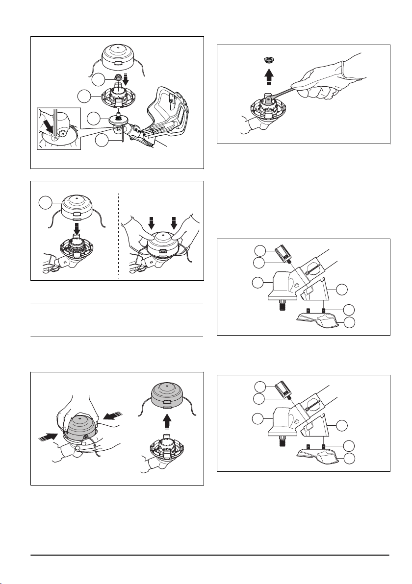
5. Install the nut (G).
H
B
C
G
6. Install the line chute and the trimmer head cover (F).
“Click”
F
To remove the trimmer head E35B (535iRXT)
Note:
To increase the life of the cord it can be soaked
in water for a couple of days before it is assembled. This
will make the cord tougher.
1. Put the locking pin in the hole to lock the shaft.
2. Press the snap-in clips on the trimmer head and
remove the trimmer head and trimmer line chute.
3. Remove the nut that holds the trimmer head and the
drive disc.
4. Remove the trimmer head.
Assembly of the saw blade guard and the saw
blade
To attach the saw blade guard (535iFR)
1. Attach the holder (A) and bracket (B) with 2 bolts (C)
on the gear housing (D).
2. Attach the saw blade guard (E) with 4 bolts (F) in the
holder (A).
B
C
D
F
A
E
To remove the saw blade guard (535iFR)
1. Remove the 4 bolts (L) from the holder (R) and
remove the saw blade guard (A).
H
J
K
L
R
A
2. Remove the 2 bolts (J) on the gear housing
(K).Remove the holder (R) and the bracket (H).
To attach the saw blade (535iFR)
1. Put the drive disc (A) on the output shaft.
2. Turn the output shaft to align 1 of the holes in the
drive disc with the related hole in the gear housing.
609 - 009 - 15.09.2022
15
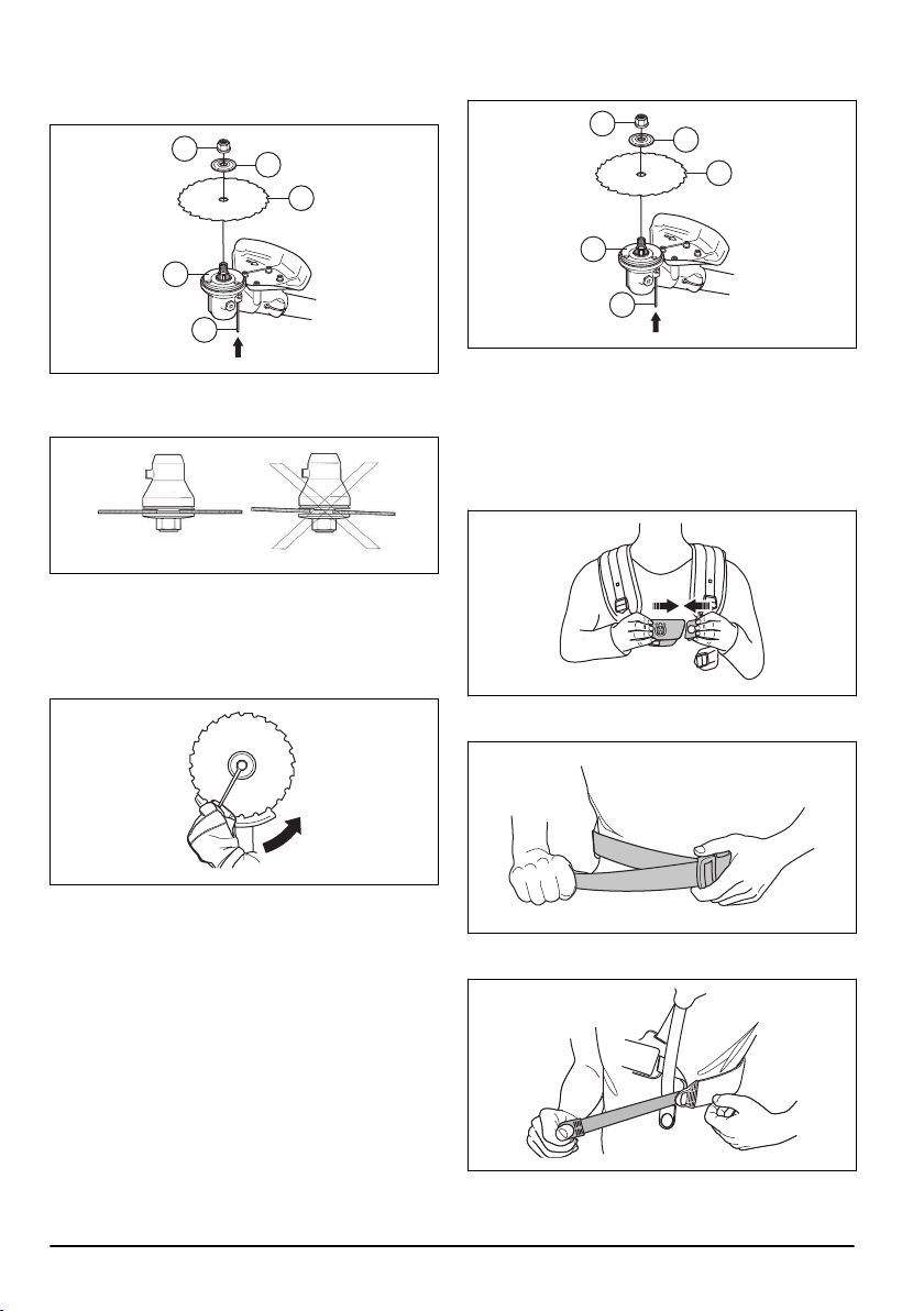
3. Put the locking pin (B) in the hole to lock the shaft.
4. Put the saw blade (C) and the support flange (D) on
the output shaft.
D
E
C
A
B
5. Make sure that the drive disc and support flange
engages correctly in the center hole of the grass
blade.
6. Attach the locknut (E).
7. Tighten the locknut with the socket wrench. Hold the
shaft of the socket wrench near the blade guard.
Tighten in the opposite direction to how the cutting
attachment rotates. Tighten it to a torque of 35-50
Nm.
To remove the saw blade (535iFR)
1. Put the locking pin (C) into the hole to lock the shaft.
2. Remove the nut the nut (G).
3. Remove the support flange (F) and the saw blade
(D) from the output shaft.
F
G
D
B
C
4. Remove the drive disc (B) from the output shaft.
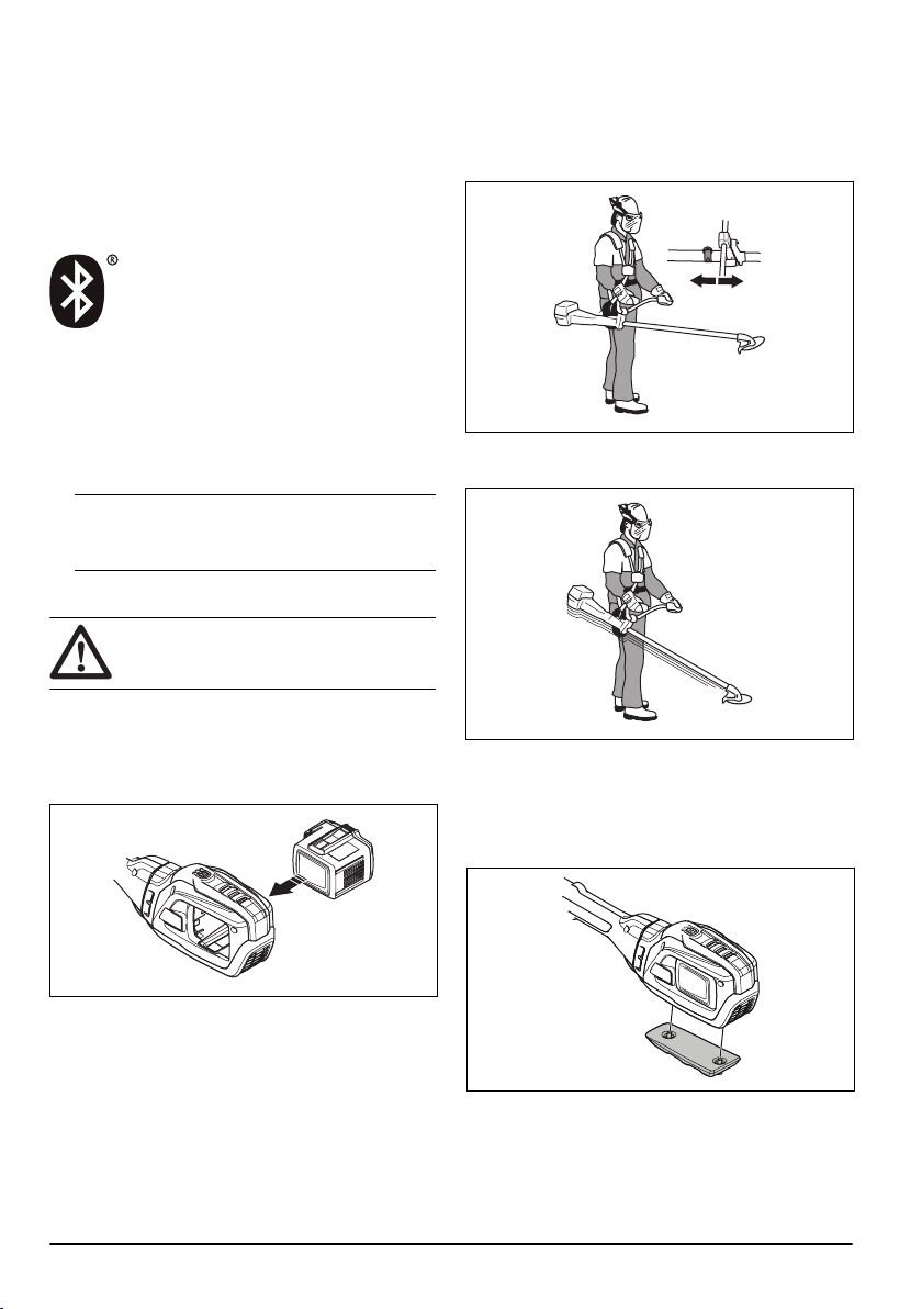
To adjust the Balance XB harness
(535iRXT)
1. Put the harness on.
2. Push the 2 parts of the breastplate together as
shown in the illustration.
3. Tighten the hip strap tightly. Make sure that the hip
strap aligns with the hip.
4. Tighten the chest strap below your left arm tightly.
The chest strap must be tight against your body.
16
609 - 009 - 15.09.2022
5. Adjust the shoulder strap until the weight is equal on
the 2 shoulders.
6. Adjust the height of the suspension point.
For forestry clearing, the correct height of the
suspension is approximately 10 cm below your hip.
Refer to
Correct balance of the product on page 18
.
7. Attach the battery carrier to the harness.
Note: It is possible to attach 1 extra battery to the
battery carrier. The battery carrier is available as an
accessory.
8. Attach a battery.
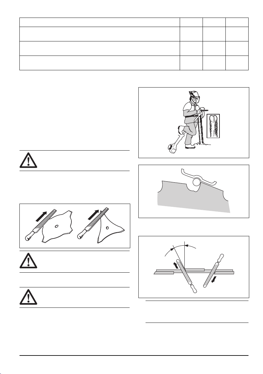
To adjust the harness (535iFR,
535iRX)
WARNING: Always attach this product
to the harness correctly. If not, you cannot
control the product safely and this can result
in injury to you or others. Do not use a
harness with a defective quick release.
WARNING: Use the harness quick
release function if you must release from the
product and the harness in an emergency
situation.
1. Put on the harness.
2. Adjust the harness for the best work position.
3. Adjust the side straps until the weight is equally
applied across your shoulders.
4. Adjust the harness until the cutting attachment is
parallel to the ground.
5. If the operation is to cut grass, let the cutting
attachment stay lightly on the ground. Adjust the
harness clamp to balance the product correctly.
Operation
Introduction
WARNING: Read and understand the
safety chapter before you use the product.
Husqvarna Connect
Husqvarna Connect is a free app for your mobile device.
The Husqvarna Connect app gives extended functions
for your Husqvarna product.
• Extended product information.
609 - 009 - 15.09.2022 17
• Information about, and help with, product parts and
servicing.
Bluetooth
®
wireless technology
Products with built-in Bluetooth
®
wireless technology
can connect to mobile devices and enables additional
functions from Husqvarna connect.
The symbol for
Bluetooth
®
wireless technology comes
on when your mobile device is connected to the product.
To start to use Husqvarna Connect
1. Download the Husqvarna Connect app on your
mobile device.
2. Register in the Husqvarna Connect app.
3. Follow the instruction steps in the Husqvarna
Connect app to connect and register the product.
Note: Husqvarna Connect app is not available for
download in all markets. Speak to your servicing
dealer for more information.
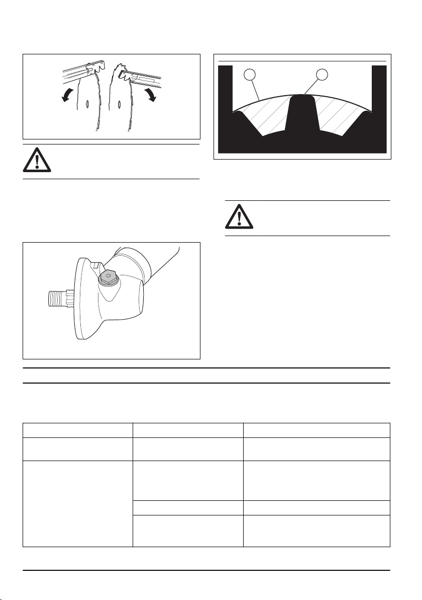
To connect the battery to the product
WARNING: Only use original
Husqvarna battery in the product.
1. Make sure that the battery is fully charged.
2. Slide the battery into the battery holder of the
product. The battery must slide easily, if not, it is not
installed correct. The battery will lock into position
when you hear a click.
3. Make sure the battery is installed correctly.
Work position
• Hold the product with 2 hands.
• Hold the product on the right side of your body.
• Keep the cutting attachment below waist level.
• Always keep the product attached to the harness.
• Keep body parts away from the hot surfaces.
• Keep body parts away from the cutting attachment.
Correct balance of the product
For forestry clearing, the product is correctly balanced
when it freely hangs horizontally from the suspension
point. With correct balance, the risk of hitting stones if
you release the handlebar is decreased.
For grass clearing, the product is correctly balanced
when the blade is at cutting height near the ground.
To adjust the balance with the add-on weight
If correct balance is difficult to achieve, attach the
add-on weight. The add-on weight is available as an
accessory.
• Attach the add-on weight with the bolts.
To apply the load equally on the
shoulders
1. Adjust the tension of the side straps to apply the
weight equally on the shoulders.
18
609 - 009 - 15.09.2022
2. Adjust the harness for the best work position. An
adjusted harness and product makes operation
easier.
Before you operate the product
• Examine the work area to make sure that you know
the type of terrain, the slope of the ground and if
there are obstacles such as stones, branches and
ditches.
• Do an overhaul inspection of the product.
• Do the safety inspections, maintenance and
servicing that are given in this manual.
• Make sure that all covers, guards, handles and the
cutting equipment are correctly attached and not
damaged.
• Make sure that there are no cracks at the bottom of
the saw blade or grass blade teeth or by the center
hole of the blade. Replace the blade if it is damaged.
• Examine the support flange for cracks. Replace the
support flange if it is damaged.
• Make sure that the locknut can not be removed
by hand. The locknut must have a locking force
of minimum 1.5Nm. Make sure that the tightening
torque is between 35-50 Nm.
• Examine the blade guard for damages or cracks.
Replace the blade guard if it has been hit or if it has
cracks.
• Examine the trimmer head and cutting attachment
guard for damages or cracks. Replace the trimmer
head and cutting attachment guard if they have been
hit or if they have cracks.
To start the product
Note: The product identifies the cutting attachment
when the cutting attachment is changed and the power
trigger is pressed. The product stops and the LED
flashes until the power trigger is released and moves
back to its initial position. The cutting attachment is at
this time identified and prepared for operation.
1. Push and hold the start button until the green battery
LED and the white mode LED comes on.
2. Use the power trigger to control the speed.
To limit the maximum speed with the
mode button
Note:
The maximum speed is related to the cutting
equipment that is attached and identified by the product.
When a blade is attached, the maximum speed is
higher than when a trimmer head is attached. Refer to
Technical data on page 27
.
The product has a mode button. With the mode button
the operator can limit the maximum speed. The mode
button has 3 speed levels. A lower level increases the
time of operation for the product. Use level 1 and level
2 if the operation does not require full speed/full power.
If the operation condition requires full speed/full power,
use level 3.Do not use a higher level than necessary for
the operation.
609 - 009 - 15.09.2022
19

1. Push the mode button to set a limit to the maximum
speed. The white LEDs comes on to show that the
function is on.
2. Press the Mode button again to choose the next
speed level.
To extend the trimmer line with the
ErgoFeed function (535iRXT)
CAUTION: Do not hit the ground with
the trimmer head to extend the trimmer line.
The product has a function that extend the trimmer line
when the ErgoFeed button is pushed. The ErgoFeed
function decrease the wear on the trimmer head. It
also decreases accidental line supply that can occur
when you hit objects, for example, stones and/or hard
surfaces.
• Push the ErgoFeed button to start the automatic
adjustment of the trimmer line.
Automatic shutdown function
The product has a shutdown function that stops the
product if the product is not used. The green LED for
start/stop indication goes off and the product stops after
180 seconds.
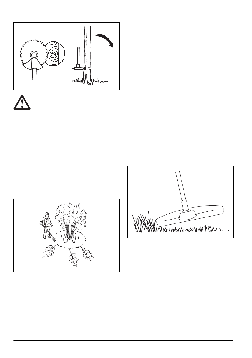
Blade thrust
A blade thrust is when the product moves to the side
quickly and with force. A blade thrust occurs when the
grass blade hits or catches on an object that cannot be
cut. A blade thrust can eject the product or operator in
all directions. There is a risk of injury to the operator and
bystanders.
The risk increases in areas where it is not easy to see
the material that should be cut.
Do not cut with the area of the blade that is shown in
grey in the illustration. The speed and movement of the
blade can cause blade thrust. The risk increases with
the thickness of the stem that is cut.
General work instructions
WARNING: Be careful when you cut a
tree that is in tension. It can spring back to
its normal position before or after the cut and
hit you or the product, and cause injury.
• Clear an open space at one end of the work area,
and start the work from there.
• Move in a regular pattern across the work area.
• Move the product fully to the left and right, to clear a
width of 4–5 m on each turn.
• Clear a length of 75 m before you turn and go back.
• Move in a direction where you do not go across
ditches and obstacles more than necessary.
20
609 - 009 - 15.09.2022
• Move in a direction where the wind makes the cut
vegetation fall in the cleared area.
• Move along slopes, not up and down.
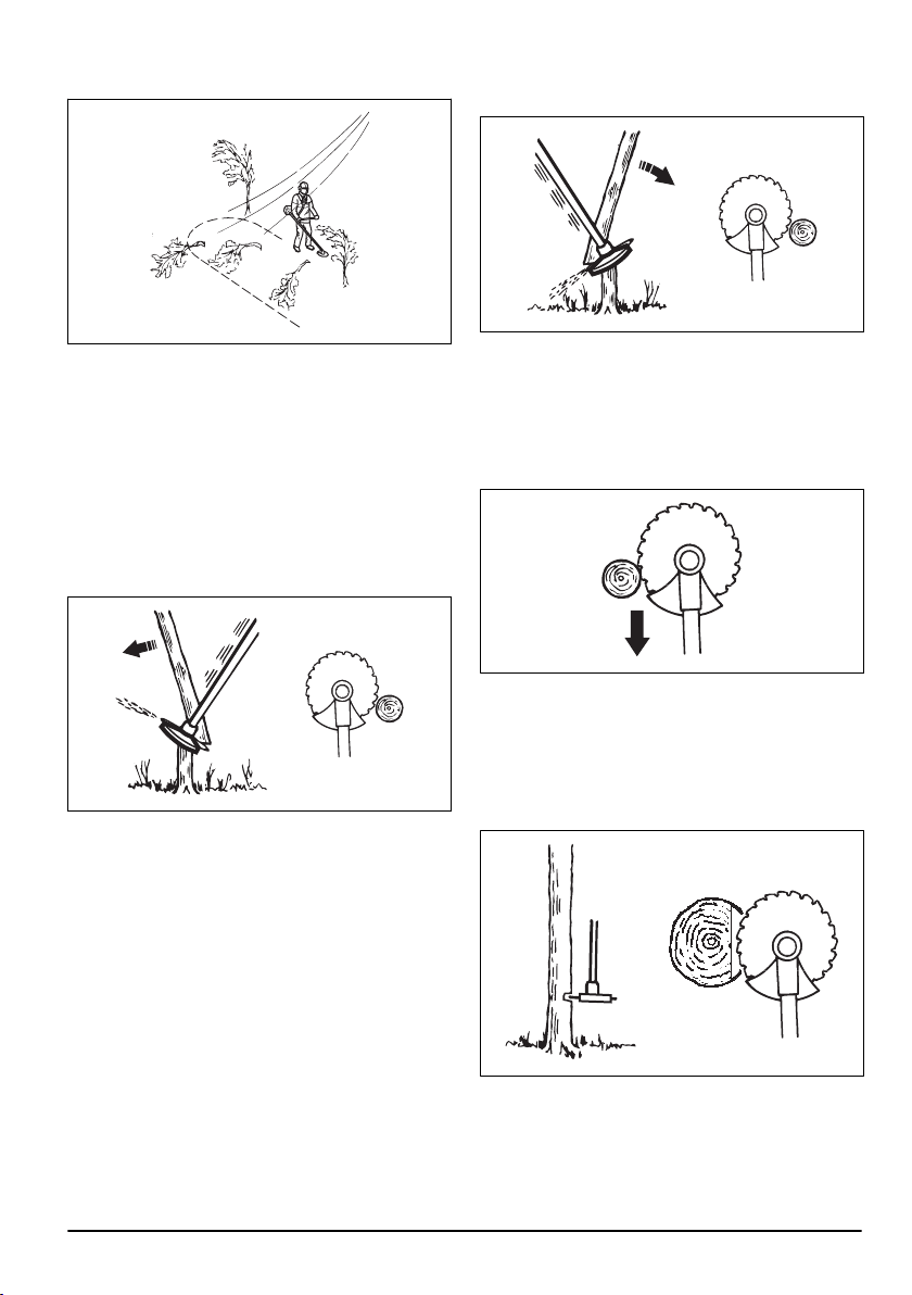
Forestry clearing with a saw blade
To fell a tree to the left
To fell to the left, push the bottom of the tree to the right.
1. Apply full throttle.
2. Put the saw blade against the tree as given in the
picture.
3. Tilt the saw blade and push it with force diagonally
down to the right. At the same time, push the tree
with the blade guard.
To fell a tree to the right
To fell to the right, push the bottom of the tree to the left.
1. Apply full throttle.
2. Put the saw blade against the tree as given in the
picture.
3. Tilt the saw blade and push it with force diagonally
up and to the right. At the same time, push the tree
with the blade guard.
To fell a tree forward
To fell forward, push the bottom of the tree rearward.
1. Apply full throttle.
2. Put the saw blade against the tree as given in the
picture.
3. Pull the saw blade forward with a fast movement.
To fell large trees
Large trees must be cut from 2 sides.
1. Examine in which direction the tree will fall.
2. Apply full throttle.
3. Do the first cut on the side of the tree to which it will
fall.
609 - 009 - 15.09.2022
21
4. Cut through the tree from the other side.
CAUTION: If the saw blade becomes
blocked, do not pull the product with a
sudden movement. That can cause damage
to the saw blade, bevel gear, shaft or
handlebar. Release the handles, hold the
shaft with 2 hands and carefully pull the
product.
Note: Use more cutting pressure fo fell small trees.
Use less cutting pressure to fell large trees.
Brush cutting with a saw blade
To fell to the left, push the bottom of the tree to the right.
• Cut down thin trees and brush.
• Move the product from side to side.
• Cut many trees in one movement.
• For groups of thin trees:
a) Cut the outer trees high up.
b) Cut the outer trees to the correct height.
c) Cut from the center. If you cannot get access to
the center, cut the outer trees high up and let
them fall. This decreases the risk that the saw
blade becomes blocked.
To clear grass with a grass blade
1. Grass blades and grass cutters must not be used on
woody stems.
2. A grass blade is used for all types of tall or coarse
grass.
3. The grass is cut down with a sideways, swinging
movement, where the movement from right-to-left
is the clearing stoke and the movement from left-to-
right is the return stoke. Let the left-hand side of the
blade (between 8 and 12 o'clock) do the cutting.
4. If the blade is angled to the left when clearing grass,
the grass will collect in a line, which makes it easier
to collect, e.g. by raking.
5. Try to work rhythmically. Stand firmly with your feet
apart. Move forward after the return stoke and stand
firmly again.
6. Let the support cup rest lightly against the ground. It
is used to protect the blade from hitting the ground.
7. Reduce the risk of material wrapping around the
blade by always work at full speed and avoid the
previously cut material during the return stoke.
8. Stop the motor, unclip the harness and place the
machine on the ground before you start to collect the
cut material.
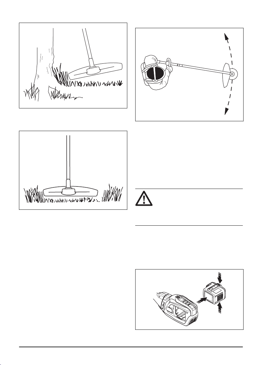
Grass trimming with a trimmer head
To trim the grass
1. Hold the trimmer head immediately above the
ground at an angle.
Do not push the grass trimmer line into the grass.
2. Decrease the length of the grass trimmer line by
10-12 cm (4-4.75 in) and decrease the motor speed
to decrease the risk of damage to plants.
22
609 - 009 - 15.09.2022
3. Use 80 % speed when you cut grass near objects.
To cut the grass
1. Make sure that the grass trimmer line is parallel to
the ground when you cut.
2. Do not push the trimmer head to the ground. The
ground and the product can be damaged.
3. Do not let the trimmer head touch the ground
continuously, it can cause damage to the trimmer
head.
4. Use full speed when you move the product from side
to side to cut grass.
Make sure that the grass trimmer line is parallel to
the ground.
To sweep the grass
The airflow from the rotating trimmer line can be used to
remove cut grass from an area.
1. Hold the trimmer head and the trimmer line parallel
to the ground and above the ground.
2. Apply full throttle.
3. Move the trimmer head from side to side and sweep
the grass.
WARNING:
Clean the trimmer head
cover each time you assemble new trimmer
line to prevent unbalance and vibrations in
the handles. Also do a check of the other
parts of the trimmer head and clean it if
necessary.
To stop the product
1. Release the power trigger and the power trigger
lockout.
2. Press the start/stop button until the green LED is out.
3. Press the release buttons on the battery and pull the
battery out.
609 - 009 - 15.09.2022
23

Maintenance
Introduction
WARNING: Before you do any
maintenance work you must read and
understand the safety chapter.
Maintenance schedule
WARNING: Remove the battery before
you do maintenance.
The following is a list of the maintenance steps that you
must do on the product.
Maintenance Daily Weekly Monthly
Clean the external parts of the product with a dry cloth. Do not use water. X
Examine that the start and stop button works correctly and is not damaged. X
Make sure that the power trigger and the power trigger lockout function correctly
from a safety point of view.
X
Make sure that all controls work and are not damaged. X
Keep the handles dry, clean and free from oil and grease. X
Make sure that the cutting attachment is not damaged. Replace the cutting
attachment if it is damaged.
X
Make sure that the cutting attachment guard is not damaged. Replace the cut-
ting attachment guard if it is damaged.
X
Make sure that the screws and nuts are tight. X
Make sure that the battery release buttons on the battery works and locks the
battery in the product.
X
Examine that the battery charger is not damaged and function correctly. X
Make sure that the battery is not damaged. X
Make sure that the suspension ring is not damaged. X
Make sure that the handle and the handlebar is not damaged and attached
correctly.
X
Make sure that the blade is correctly centered, is sharp, and not damaged. An
off-center blade will cause vibration that could result in damage to the product.
X
Make sure that the locknut of the cutting equipment is tightened correctly. X
Make sure that the transport guard for the blade is not damaged and that the
transport guard can be attached correctly.
X
Examine all couplings and connections. Make sure they are not damaged and
free from dirt.
X
Examine the vibration damping elements and make sure that they are not dam-
aged.
X
Make sure that the bevel gear is filled correctly with grease, see
To lubricate the
bevel gear on page 26
. If not, use Husqvarna bevel gear grease.
X
Lubricate the drive shaft end in the lower shaft coupling. X
24 609 - 009 - 15.09.2022
Maintenance Daily Weekly Monthly
Make sure that the air intake of the motor is not dirty. Clean the air intake with
compressed air.
X
Do a check of the connections between the battery and the product. Do a check
of the connection between the battery and the battery charger.
X
Make sure that the safety release on the harness is not damaged and operates
correctly.
X
To clean the product, the battery and
the battery charger
1. Clean the product with a dry cloth after use.
2. Clean the battery and battery charger with a dry
cloth. Keep the battery guide tracks clean.
3. Make sure that the terminals on the battery and the
battery charger are clean before the battery is put in
the battery charger or the product.
To sharpen the grass knife and grass
blade
WARNING: Stop the product and
remove the battery. Use protective gloves.
• To sharpen the grass knife or grass blade correctly,
refer to the instructions that come with the cutting
attachment.
• Sharpen all edges equally to keep the balance.
• Use a single-cut flat file.
WARNING: Always discard a blade
that is damaged. Do not try to make a bent
or twisted blade straight and use it again.
To sharpen the saw blade
WARNING: Stop the product and
remove the battery. Use protective gloves.
• To sharpen the blade correctly, refer to the
instructions that come with the blade.
• Make sure that the product and blade has sufficient
support when you sharpen it.
• Use a 5.5 mm (7/32 in) round file with a file holder.
• Hold the file at an angle of 15°.
• Sharpen one tooth of the saw blade to the right and
the next tooth to the left, see the illustration.
15˚
Note: Sharpen the edges of the teeth with a flat
file if the blade is heavily worn. Continue to sharpen
with a round file.
• Sharpen all edges equally to keep the blade
balanced.
609 - 009 - 15.09.2022
25
• Adjust the blade set to 1 mm (0.04 in) with the
recommended setting tool. Refer to the instructions
that come with the blade.
WARNING: Always discard a blade
that is damaged. Do not try to make a bent
or twisted blade straight and use it again.
To lubricate the bevel gear
1. Remove the cutting equipment.
2. Put the product with the grease plug at its highest
position.
3. Remove the grease plug.
4. Look into the grease plug hole and turn the drive
shaft. The grease level (A) must be in level with the
top of the gear cogs (B).
A B
5. If the grease level is too low fill the bevel gear with
Husqvarna bevel gear grease. Fill slowly and turn
the drive shaft as you apply the bevel gear grease,
stop at the correct level (B).
CAUTION: An incorrect quantity of
grease can cause damage to the bevel
gear.
6. Install the grease plug.
Troubleshooting
User interface
LED display Possible faults Possible action
Battery LED indicator flashes or-
ange
Low battery voltage. Charge the battery.
Red error LED flashes Overload. The cutting attachment is jammed. deacti-
vate the product. Remove the battery. Clean
the cutting attachment from unwanted mate-
rials.
Temperature deviation. Let the product cool down.
The power trigger and the acti-
vate button are pressed at the
same time.
Release the power trigger and the product is
active.
26 609 - 009 - 15.09.2022

LED display Possible faults Possible action
The product does not start Dirt in the battery connectors. Clean the battery connectors with com-
pressed air or a soft brush.
Error LED is lit with red light The product needs servicing. Contact your servicing agent.
Transportation, storage and disposal
Transportation and storage
• The supplied Li-ion batteries obey the Dangerous
Goods Legislation requirements.
• Obey the special requirement on package and labels
for commercial transportation, including by third
parties and forwarding agents.
• Speak to a person with special training in dangerous
material before you send the product. Obey all
applicable national regulations.
• Use tape on open contacts when you put the battery
in a package. Put the battery in the package tightly
to prevent movement.
• Remove the battery for storage or transportation.
• Put the battery and the battery charger in a space
that is dry and free from moisture and frost.
• Do not keep the battery in an area where static
electricity can occur. Do not keep the battery in a
metal box.
• Put the battery in storage where the temperature is
between 5°C/41°F and 25°C/77°F and away from
open sunlight.
• Put the battery charger in storage where the
temperature is between 5 °C/41 °F and 45°C/113°F
and away from open sunlight.
• Use the battery charger only when the surrounding
temperature is between 5°C/41°F and 40°C/104°F.
• Charge the battery 30% to 50% before you put it in
storage for long periods.
• Put the battery charger in storage in a space that is
closed and dry.
• Keep the battery away from the battery charger
during storage. Do not let children and other not
approved persons to touch the equipment. Keep the
equipment in a space that you can lock.
• Clean the product and do a full servicing before you
put the product in storage for a long time.
• Use the transportation guard on the product to
prevent injuries or damage on the product during
transportation and storage.
• Attach the product safely during transportation.
Disposal of the battery, battery charger
and product
Symbols on the product or the package of the product
means that the product is not domestic waste. Recycle
it at a recycling station for electrical and electronic
equipment. This helps to prevent damage to the
environment and to persons.
Get in touch with your local authorities, domestic waste
service or your dealer for more information about how to
recycle your product.
Technical data
Technical data
535iFR 535iRXT 535iRX
Motor
Motor type Husqvarna e-torq
BLDC
Husqvarna e-torq
BLDC
Husqvarna e-torq
BLDC
Speed of output shaft. Trimmer head/blade,
1/min
5300/8200 5300/8200 5300/8200
Cutting width, mm/in 450/17.7 450/17.7 450/17.7
Weight
Weight without battery, kg/lb 4.5/9.9 4.9/10.8 4.9/10.8
609 - 009 - 15.09.2022 27

535iFR 535iRXT 535iRX
Noise emissions
Sound power level, measured dB (A) 93 93 94
Sound power level, guaranteed L
WA
dB (A) 96 96 96
Noise levels
1
Sound pressure level at the operator's ear,
measured according to IEC 62841-1:
Equipped with trimmer head (original) dB (A) 80 80 80
Vibration levels
2
Vibration levels at handles, measured ac-
cording to IEC 62841-1, m/s
2
Equipped with trimmer head (original), left/
right, m/s
2
1.4/1.7 1.2/1.4 1.3/1.4
Equipped with grass blade (original), left/
right, m/s
2
2.5/2.0 2.4/2.0 2.4/2.0
Note: For comparison of vibrations levels, battery and combustion products use the vibration calculator. https://
www.husqvarna.com/uk/services-solutions/vibration-calculator/
Radio frequency data for Bluetooth
®
Frequency band, GHz 2.4-2.4835 2.4-2.4835 -
Output power, max dBm 0 0 0 -
Approved batteries
Battery
BLi300
Type Lithium-ion
Battery capacity, Ah 9.4
Nominal voltage, V 36
Weight, kg (lb) 1.9 (4.2)
Approved battery chargers
Battery charger
QC500
Input voltage, V 100-240
Frequency, Hz 50-60
1
Reported data for sound pressure level for the machine has a typical statistical dispersion (standard deviation)
of 3 dB (A).
2
Reported data for vibration level has a typical statistical dispersion (standard deviation) of 1.5 m/s
2
.
28 609 - 009 - 15.09.2022

Battery charger QC500
Power, W 500
Accessories
Accessories
Approved accessories Accessory type Cutting attachment guard, art. no.
Centre hole in blades/knives, Ø 25.4 mm
Output shaft thread M12
Grass blade/grass knife
Multi 255-3 (Ø 255, 3 teeth) 590 88 00-01
Grass 255-4 (Ø 255, 4 teeth) 590 88 00-01
Multi 300-3 (Ø 300 3 teeth) 590 88 00-01
Saw blade Scarlet 200-22 (Ø 200, 22 teeth) 501 32 04-03
Trimmer head
T35, T35x (Ø 2.4 -2.7 mm Whisper
twist trimmer line)
590 88 01-01
E35B (Ø 2.4 -2.7 mm Whisper twist
trimmer line)
590 88 01-01
Support cup Fixed
Accessory type Article number
Battery carrier 590 11 42-01
Balance XB 597 33 12-01
609 - 009 - 15.09.2022 29

Declaration of Conformity
EU Declaration of conformity
We, Husqvarna AB, SE-561 82 Huskvarna, Sweden, tel:
+46-36-146500, declare on our sole responsibility that
the product:
Products without Bluetooth
®
Description Battery-operated brushcutter / grass trimmer
Brand
Husqvarna
Type / Model 535iFR, 535iRXT, 535iRX
Identification Serial numbers dating from 2021 and onwards
complies fully with the following EU directives and
regulations:
Regulation Description
2006/42/EC "relating to machinery"
2014/30/EU "relating to electromagnetic compatibility"
2014/53/EU ”relating to radio equipment”
2011/65/EU “relating to restriction of hazardous substances”
2000/14/EC "relating to outdoor noise"
and that the following standards and/or technical
specifications are applied: EN 62841-1:2015,
EN ISO 11806-1:2011, EN 61000-6-1:2007, EN
61000-6-3:2007+A1:2011, EN IEC 63000:2018 .
0404, RISE SMP Svensk Maskinprovning AB, Box 7035,
SE-750 07 Uppsala, Sweden has carried out a voluntary
examination on behalf of Husqvarna AB. The certificate
has the number: SEC/19/2533
Notified body: 0404, RISE SMP Svensk Maskinprovning
AB, Box 7035, SE-750 07 Uppsala, Sweden
has certified conformity with the council's directive
2000/14/EC, conformity assessment procedure: Annex
VI.
For information relating to noise emission, refer to
Technical data on page 27
.
Huskvarna, 2022-04-11
Stefan Holmberg, R&D Director, Technology
Management, Husqvarna AB
Responsible for technical documentation
30 609 - 009 - 15.09.2022

EU Declaration of conformity
We, Husqvarna AB, SE-561 82 Huskvarna, Sweden, tel:
+46-36-146500, declare on our sole responsibility that
the product:
Products with Bluetooth
®
Description Battery-operated brushcutter / grass trimmer
Brand Husqvarna
Type / Model 535iFR, 535iRXT, 535iRX
Identification Serial numbers dating from 2021 and onwards
complies fully with the following EU directives and
regulations:
Regulation Description
2006/42/EC "relating to machinery"
2014/53/EU ”relating to radio equipment”
2011/65/EU “relating to restriction of hazardous substances”
2000/14/EC "relating to outdoor noise"
and that the following standards and/or technical
specifications are applied: EN 62841-1:2015,
EN ISO 11806-1:2011, EN 61000-6-1:2007, EN
61000-6-3:2007+A1:2011, EN IEC 63000:2018, ETSI
EN 301 489-1 v.2.1.1, ETSI EN 301 489-17 v.3.1.1,
ETSI EN 300 328 v2.2.2.
0404, RISE SMP Svensk Maskinprovning AB, Box 7035,
SE-750 07 Uppsala, Sweden has carried out a voluntary
examination on behalf of Husqvarna AB. The certificate
has the number: SEC/19/2533
Notified body: 0404, RISE SMP Svensk Maskinprovning
AB, Box 7035, SE-750 07 Uppsala, Sweden
has certified conformity with the council's directive
2000/14/EC, conformity assessment procedure: Annex
VI.
For information relating to noise emissions, refer to
Technical data on page 27
.
Huskvarna, 2022-04-11
Stefan Holmberg, R&D Director, Technology
Management, Husqvarna AB
Responsible for technical documentation
609 - 009 - 15.09.2022 31

Declaration of conformity
We, Husqvarna AB, SE-561 82 Huskvarna, Sweden, tel:
+46-36-146500, declare on our sole responsibility that
the product:
Products without Bluetooth
®
Description Battery-operated brushcutter / grass trimmer
Brand
Husqvarna
Type / Model 535iFR, 535iRXT, 535iRX
Identification Serial numbers dating from 2021 and onwards
complies fully with the following UK regulations:
Regulations
The Supply of Machinery (Safety) Regulations 2008
Electromagnetic Compatibility Regulations 2016
The Restriction of the Use of Certain Hazardous Substances in Electrical and Electronic Equipment Regulations
2012
The Noise Emission in the Environment by Equipment for use Outdoors Regulations 2001
The Radio Equipment Regulations 2017
and that the following standards and/or technical
specifications are applied: EN 62841-1:2015,
EN ISO 11806-1:2011, EN 61000-6-1:2007, EN
61000-6-3:2007+A1:2011, EN IEC 63000:2018 .
Approved body: 0888, HORIBA MIRA Certification Ltd.,
Watling Street, Nuneaton, Warwickshire, CV10 0TU,
UK has certified conformity with the Outdoor Noise
Regulations of 2001, conformity assessment procedure:
Schedule 9.
For information relating to noise emissions, refer to
Technical data on page 27
.
Huskvarna, 2022-04-11
Stefan Holmberg, R&D Director, Technology
Management, Husqvarna AB
Responsible for technical documentation
UK Importer:
Husqvarna UK Ltd
Preston Road, Co. Durham
DL5 6UP
32 609 - 009 - 15.09.2022

UK Declaration of conformity
We, Husqvarna AB, SE-561 82 Huskvarna, Sweden, tel:
+46-36-146500, declare on our sole responsibility that
the product:
Products with Bluetooth
®
Description Battery-operated brushcutter / grass trimmer
Brand Husqvarna
Type / Model 535iFR, 535iRXT, 535iRX
Identification Serial numbers dating from 2021 and onwards
complies fully with the following UK regulations:
Regulations
The Supply of Machinery (Safety) Regulations 2008
The Restriction of the Use of Certain Hazardous Substances in Electrical and Electronic Equipment Regulations
2012
The Noise Emission in the Environment by Equipment for use Outdoors Regulations 2001
The Radio Equipment Regulations 2017
and that the following standards and/or technical
specifications are applied: EN 62841-1:2015,
EN ISO 11806-1:2011, EN 61000-6-1:2007, EN
61000-6-3:2007+A1:2011, EN IEC 63000:2018, ETSI
EN 301 489-1 v.2.1.1, ETSI EN 301 489-17 v.3.1.1,
ETSI EN 300 328 v2.2.2.
Approved body: 0888, HORIBA MIRA Certification Ltd.,
Watling Street, Nuneaton, Warwickshire, CV10 0TU,
UK has certified conformity with the Outdoor Noise
Regulations of 2001, conformity assessment procedure:
Schedule 9.
For information relating to noise emissions, refer to
Technical data on page 27
.
Huskvarna, 2022-04-11
Stefan Holmberg, R&D Director, Technology
Management, Husqvarna AB
Responsible for technical documentation
UK Importer:
Husqvarna UK Ltd
Preston Road, Co. Durham
DL5 6UP
Registered trademarks
The
Bluetooth
®
word mark and logos are registered
trademarks owned by
Bluetooth SIG, inc.
and any use
of such marks by Husqvarna is under license.
609 - 009 - 15.09.2022 33

34 609 - 009 - 15.09.2022

609 - 009 - 15.09.2022 35

www.husqvarna.com
Original instructions
1142851-26
2022-10-11