Loading ...
Loading ...
Loading ...
Rinnai 18 EHPA_VMA Series 2 Heat Pump OIM
CONNECT THE PTR VALVE
Connect the PTR valve to the uppermost tting of the storage cylinder. See the diagram on page the section
‘Dimensions’ on page 13.
The PTR pressure rating MUST be suited for the cylinder and adequate for the thermal loading applied to the
storage cylinder, as specied in the table on 12. The supplied PTR valve input rating is 10.0 kW. The PTR
valve rating MUST EXCEED the total input from the heat pump. For example, the maximum output from the
EHPA_A250VM is 4.29 kW (see the table on page 12). This is less than 10.0 kW, hence the supplied PTR valve
is of sufcient capacity.
Use Teon thread tape on the valve, never use hemp or other sealing materials. Ensure the tape does not protrude
past the end of the thread, which could result in it hanging over the end of the thread and blocking the water
passage through the valve.
The PTR valve MUST be installed on the connection marked ‘hot water outlet’ near the top of the cylinder. Leave
the valve outlet pointing down. Tighten the valve using the spanner ats - never use the valve body.
Connect the supplied PTR valve into the top socket marked “Relief Valve” and discharge according to plumbing
regulations. PTR Valves for the unit are rated at 1000kpa.
The drain line from this valve MUST run in a continuously downward direction with the discharge end left
permanently open to atmosphere.
PLUMBING CONNECTIONS
Refer to the diagram on page 13 for detailed information on position of plumbing.
An approved isolating valve, non return valve, line strainer, and union MUST be tted between the supply main
and the RP ¾ socket in the water heater. All ttings MUST be approved by the relevant installation Authority.
An ECV MUST be tted in Western Australia and South Australia to the cold water supply to the storage cylinder
to comply with local regulations.
An ECV is recommended in all other geographical areas where the water supply has a tendency to cause scaling.
This will reduce hot water discharge from the pressure and temperature relief (PTR) valve which minimises wear
on this valve.
This water heater is designed for direct connection to water supply pressures of no greater than those specied on
page 12. Where the mains pressure can exceed or uctuate beyond this, a pressure limiting device (complying
with AS1357) MUST be tted.
CONNECT COLD / HOT WATER SUPPLY
Connect cold water supply, Pressure Limiting Valve (PLV) and or Expansion Control Valve (ECV).
Connect cold water supply to the storage tank (refer to Diagram BELOW).
A stop cock, non return valve and line strainer MUST be tted.
Connect the pipe work supplying hot water to the premises to the hot water outlet on the tank.
A temperature limiting device may be required as detailed in the section the section ‘Hot Water Delivery Temperature’
on page 16
It is recommended that all hot water lines are insulated with high temperature, UV resistant 13mm closed cell
insulation.
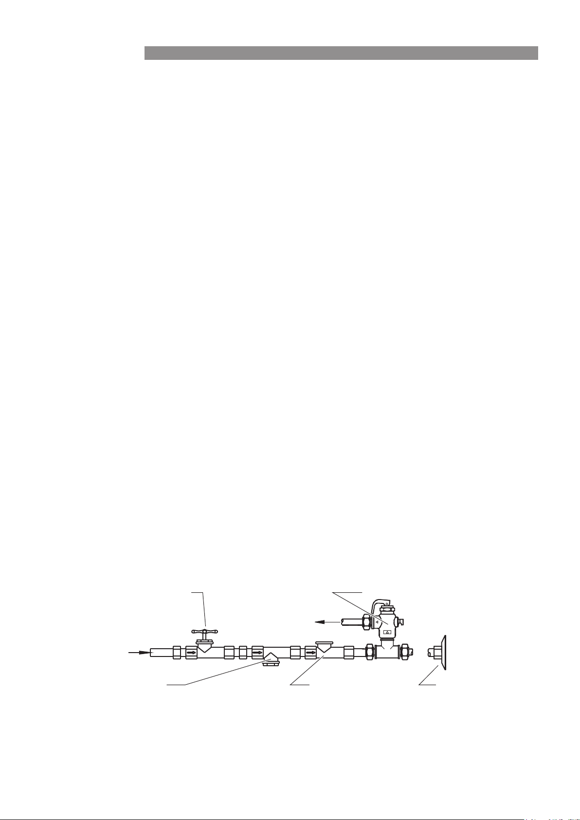
D ra in
Union Connection
Non-return ValveLine Strainer
Cold Water Inlet
Isolating Valve (Spindle Vertical)
Cold water expansion
control valve
INSTALLATION
Loading ...
Loading ...
Loading ...