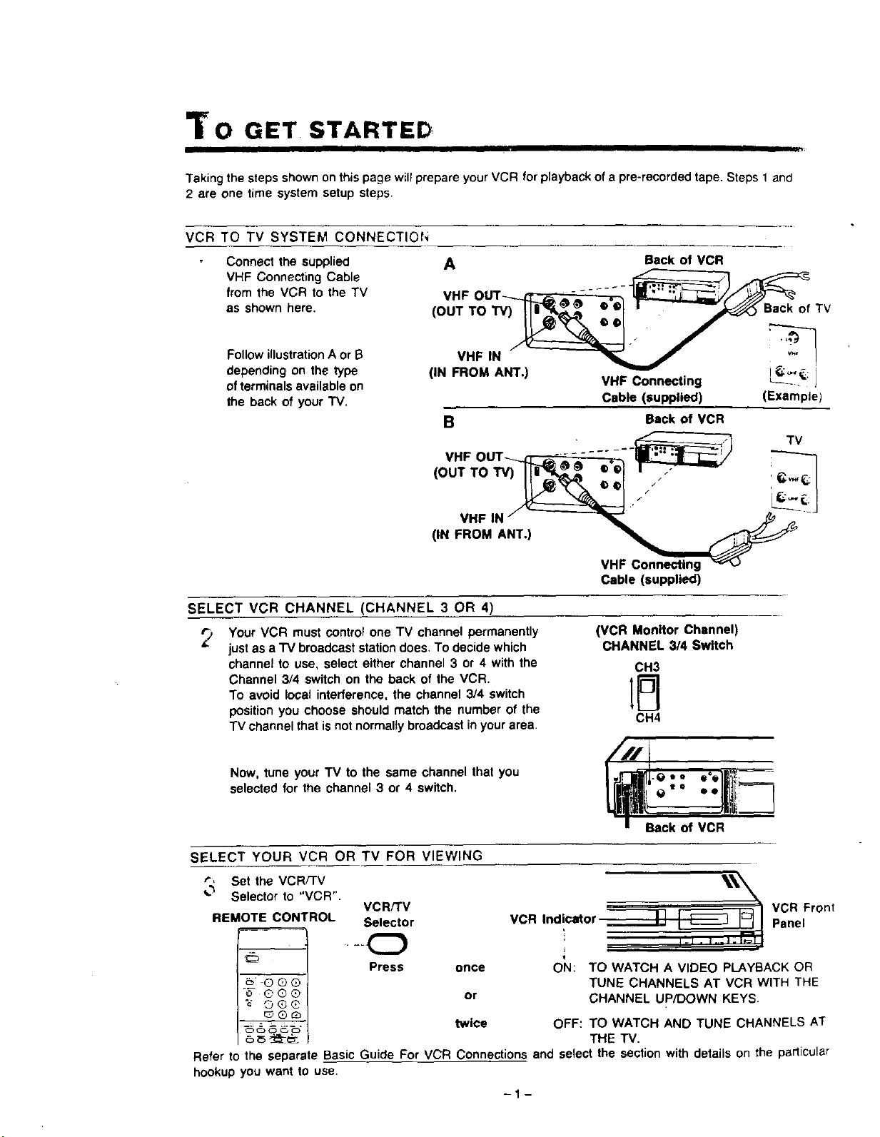
To GET STARTED
I I
Taking the steps shown on this page will prepare your VCR for playback of a pre-recorded tape. Steps 1 and
2 are one time system setup steps.
VCR TO TV SYSTEM CONNECTIOI-,
Connect the supplied
VHF Connecting Cable
from the VCR to the TV
as shown here.
Follow illustrationA or B
depending on the type
of terminals available on
the back of your "IV.
A Back of VCR
._-'----------_7_._=:-=:-=:-=:-=:-=_
VHF OUT_ ,, _'@ ..... ."-__'_ _
(OUTTOW)_li_ _ _ ° _1r_'-'_s.ck ofTV
• • , .,.'_
(IN FROM ANT.) VHF Connecting _2_'; I
Cable (supplied) (Example)
B Back of VCR
._-.______.q_- TV
VHF OUT .... - ..... . II1-.- .;liar-- /
(OUTTO,V) ._,l I
1,."
(1.
VHF Connecting
Cable (supplied)
SELECT VCR CHANNEL (CHANNEL 3 OR 4)
_., Your VCR must cOntrol one TV channel permanently
just as a "IV broadcast station does. To decide which
channel to use, select either channel 3 or 4 with the
Channel 3/4 switch on the back of the VCR.
To avoid local interference, the channel 3/4 switch
position you choose should match the number of the
TV channel that is not normally broadcast in your area.
Now, tune your TV to the same channel that you
selected for the channel 3 or 4 switch.
(VCR Monitor Channel)
CHANNEL 3/4 Switch
CH3
CH4
l-e.. a"l!!i!_---
e "° • olliili_-_7
SELECT YOUR VCR OR TV FOR VIEWING
r, Set the VCR/TV
_'_ Selector to "VCR".
VCR/TV
REMOTE CONTROL Selector
"_- @®®
"_ OG@
OC_O C,_
• -kO
Press once
or
twice
___ _ VCR Front
VCR Indicator _ Panel
ON: TO WATCH A VIDEO PLAYBACK OR
TUNE CHANNELS AT VCR WITH THE
CHANNEL UP/DOWN KEYS.
OFF: TO WATCH AND TUNE CHANNELS AT
THE TV.
Refer to the separate Basic Guide For VCR Connections and select the section with details on the particular
hookup you want to use.
-1-
ABLE OF CONTENTS
INTRODUCTIOr,
We are pleased to introduce to you one of the most
sophisticated viewing and entertainment products
available today.
This manual is arranged to get you started easily so
you can begin to enjoy the wodd of video as soon
as possible. On the facing page you will find the
basic steps described for setting up your VCR to
view tapes on your TV and to record. Keep this
manual handy to serve as a quick guide to the video
features on your new VCR.
PV-4820
TABLE OF CONTENTS
TO GET STARTED ....................... 1
TABLE OF CONTENTS ................... 2
DESCRIPTION OF CONTROLS ............. 3
CLOCK ADJUSTMENT .................... 8
TO PLAYBACK .......................... 9
FEATURES
• HQ (High Quality) System
• Digital Quartz Tuning with Auto Set Feature
• On Screen Display Programming
• Multi Function Display
• Recorded Time Counter (Real Time)
• Special Effects Playback
Fast Search
Double Speed Playback
Field-Still
Field Frame Advance
Double Fine Slow
• One Touch Recording
• Unattended (Timer) Recording
• Auto Operation Functions
• Wireless Remote Control
TO RECORD ............................ 1!
CHANNEL MEMORY ...................... 13
ONE TOUCH RECORDING ................ 15
TIMER RECORDING ...................... 17
HELPFUL HINTS ......................... 20
BEFORE REQUESTING SERVICE .......... 23
SPECIFICATIONS ........................ 24
WARRANTY ............................. 25
ACCESSORIES ................... Back Cover
- I
t
: • : . D2 NC'_ EXoOSE THIS EOUIPMEf:T TC, Rt..!t i '
This video recorder, equipped with the HO System, is compatible with existing VHS equipment.
Only use those tapes wlth the _ mark. It Is recommended that only cassette tapes that have been
tested and inspected for use In 2, 4, 6, and 8 hour VCR machines be used.
C,_UTI_,"dTO'_¢EoUCF T,'_ _S_: _,= ELE_"A,C S,',OC,_
This symbol warns the user that uninsulated voltage
withinthe unitmay have sufficient magnitude to cause
electric shock. Therefore, it isdangerous to make any
kind of contact with any inside part of this unit.
This symbol alerts the user that important literature
concerning the operation 8nd maintenance ofthis unit
has been included. Therefore, it should be read
carefully in order to avoid any problems.
-2-
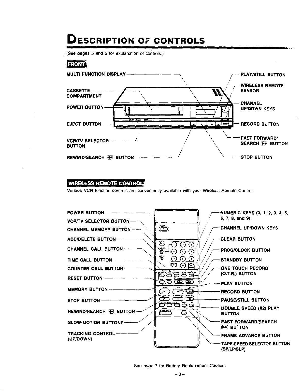
DESCRIPTION OF CONTROLS
I
. (See pages 5 and 6 for explanation of controls.)
MULTI FUNCTION DISPLAY \
\
\
\
CASSETTE
COMPARTMENT
/_-- PLAY/STILL BUTTON
.' r--WIRELESS REMOTE
SENSOR
UP/DOWN KEYS
UTTON
VCR/TV SELECTOR
BUTTON
REWIND/SEARCH 4_- BUTTON
FAST FORWARD/
SEARCH _; BUTTON
STOP BUTTON
|','_I;l-._I!;_"}--t ;1_,',_t]11:l[_l_ ="I f :{!; I_
Various VCR function controls are conveniently available with your Wireless Remote Control.
POWER BUTTON \
VCR/rV SELECTOR BUTTON--
CHANNEL MEMORY BUTTON--, •',
\
ADD/DELETE BUTTON
\
CHANNEL CALL BUTTON --_
TIME CALL BUTTON -_\
COUNTER CALL BuI-rON-
RESET Bu'r'FON
MEMORY BUTTON
STOP BUTTON
REWIND/SEARCH ,t_
SLOW-MOTION BUTTONS
f
J
TRACKING CONTROL
(UP/DOWN)
_-'--NUMERIC KEYS (0, 1, 2, 3, 4, 5.
6, 7, 8, and 9)
/
_--CHANNEL UP/DOWN KEYS
F CLEAR BUTTON
_ PROG/CLOCK BUTTON
STANDBY BUTTON
/_--ONE TOUCH RECORD
_ (O.T.R,) BUTTON
PLAY BUTTON
RECORD BUTTON
PAUSE/STILL BUTTON
DOUBLE SPEED (X2) PLAY
BUTTON
FAST FORWARD/SEARCH
BUTTON
TAPE-SPEED SELECTOR BU'I-rON
(SP/LPiSLP)
See page 7 for Battery Replacement Caution.
PV-4820
l__o_
TIMER INDICATOR--
/
VCR/TV INDICATOR
=VCR"
CASSETTE-IN ,
INDICATOR .\ \ , / CATV INDICATOR
lSu.o To
!We Th Fr _ SLP/_--_F, I
RECORD INDICATOR_ _ . "',
.f \
CLOCK DISPLAY SPEED INDICATOR
"SP" "LP" "SLP"
AUDIO INPUT
CONNECTOR
,/ VERTICAL LOCK
AUDIO OUTPUT / ADJUSTMENT
CONNECTOR CONTROL
VIDEO INPUT
CONNECTOR
VIDEO OUTPUT
CONNECTOR
CHANNEL 3/4 SWITCH-
AC POWER CORD
UHF ANTENNA
OUTPUT TERMINALS
(OUT TO TV SET)
UHF ANTENNA
INPUT TERMINALS
(IN FROM ANTENNA)
VHF ANTENNA
OUTPUT TERMINAL
(OUT TO TV SET)
VHF ANTENNA
INPUT TERMINAL
(IN FROM ANTENNA)
-4-
DESCRIPTION OF CONTROLS (CONTINUED)
FROf'T
• POWER BUTTON
- TO turn the VCR on and off.
- To set the VCR for unattended recordings after
timer settings have been completed
• VCR/TV SELECTOR BU'II'ON
VCR position: To view playback or to monitor video
recordings. "VCR" appears on the
Multi Function Display.
TV position: To watch TV or to view one program
while recording a different program.
When this is set to TV, there is no
indication on the Multi Function
Display.
• REWIND/SEARCH BUT'TON
To rewind tapes. Also, during playback press this
button to view the picture in rapid reverse.
• PLAY/STILL BUTTON
To play back a tape. In SP or SLP playback, press
this button once more to view a still picture.
WIRELESS REMOTE CONTROL
• MEMORY BUTTON
When this button is set to ON, the tape will rewind
or fast forward to the "0:00.00" point then stop
automatically.
• REWIND/SEARCH BUTTON
Same as the REWIND/SEARCH Button on the
VCR.
• SLOW-MOTION BUTTONS
Press the SLOW Button while watching a tape to
put action into slow motion for tapes recorded in
SP and SLP speeds. DOWN and UP Buttons let
you adjust slow motion speed from about 1/10 to
about 1/60 of normal speed.
• CLEAR BUTTON
Press this button to clear the settings for the
displayed program contents.
While setting the clock or a program, each press
of this button starts the digit tothe left flashing for
correction.
• FAST FORWARD/SEARCH Bu'rroN
To rapidly advance the tape. Also, during playback
press this button to do rapid forward visual search.
WIRELESS REMOTE CONTROL
• VCRfTV SELECTOR BUTTON
Same as the VCR/TV SELECTOR Button on the
VCR.
• CHANNEL MEMORY BUTTON
This button is normally OFF. For CHANNEL
MEMORY programming, hold thisbutton down and
press NUMERIC Key "1" to use the AUTO SET
feature.
• ADD/DELETE BUTTON
Used to add or delete a selected CHANNEL.
• CHANNEL CALL BUTTON
When pressing this button, the number of the
channel tuned will be displayed on the TV screen
momentarily.
• TIME CALL BUTTON
Press the TIME CALL Button to display or clear the
date and time from the TV screen.
• COUNTER CALL BUTTON
Press this button to display or clear the time counter
and tape speed display.
• RESET BUTTON
Sets the Time Counter to "0:00.001'
• PROG/CLOCK BUTTON
Press this button to display the MENU screen to
select either clock adjustment or the Timer
programming mode.
• STANDBY BUI"FON
Used along with O.T.R. Button, to set a delayed
(Standby) O.T.R..
• ONE TOUCH RECORD (O,T.R.) BUTTON
Select the channel and press the ONE TOUCH
RECORD Buttonto start recording immediately for
30 minutes to 4 hours of recording, or until tape
ends. In any case power shut off is automatic
• PAUSE/STILL BUI_ON
To temporarily stop'the tape during recording or to
view a still picture during playback.
• DOUBLE SPEED (X2) PLAY BUTTON
Press this button during playback of the tapes
recorded in SP and SLP mode forrapid tape search
at twice the normal speed,
• FAST FORWARD/SEARCH BUTTON
Same as the FAST FORWARD/SEARCH Button
on the VCR
• FRAME ADVANCE BUTTON
While viewing an SP or SLP still picture, press this
button to advance the picture one frame at a time,
or hold it down for a slow-motion picture.
• TAPE SPEED SELECTOR (SP/LPiSLP) BUTTON
Set this selector for the desired recording speed
-5-
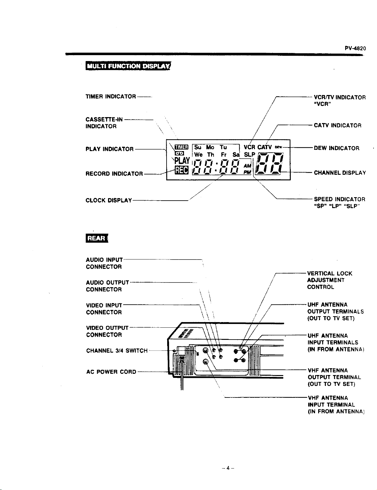
MULTIFUNCTIONDISPLAY
• TIMER INDICATOR " _"
Indicates the VCR is set for unattended recording.
• CASSETE-IN INDICATOR
The three states ofthis indicatorshow the following
conditions,
No " r'_ ,' displayed: There is no cassette in the
unit.
" _ " displayed: There is a cassette in the unit
and some interval to the end of the tape.
Flashing " E_ " display: The Automatic Rewind
took place at the end of the tape during playback,
recording or fast forward. The indicator continues
flashing until the next mode is selected.
Also flashes if you attempt any recording when the
cassette record tab is missing.
• PLAY INDICATOR
Appears during playback,
Flashes in still mode.
• RECORD INDICATOR
Appears during recording.
Flashes in record/pause mode
• CLOCK DISPLAY
Displays present day/time.
• VCR/TV INDICATOR "VCR"
Appears when the VCR/TV Selector is set to VCR.
• CATV INDICATOR
CATV indicates ANTENNA SYSTEM is set to the
Cable TV mode.
• DEW INDICATOR "DEW"
When "DEW" flashes on the Multi Function Display,
the unit will not operate due to excessive moisture
within it. If this happens, let the VCR remain at
room temperature either ON or OFF, until this
indicator disappears.
Ifthere is a cassette in the VCR, it will be ejected
when "DEW" flashes,
• CHANNEL DISPLAY " _ "
The CHANNEL number selected is displayed.
An "L" willappear to let you know you are receiving
a Line input.
• SPEED INDICATOR "SP" "LP" "SLP"
Shows the tape speed during recording and
playback,
PV,.4820
REAR
(See enclosed foldout "Basic Guide For VCR
Connections,")
• AUDIO INPUT CONNECTOR
For connection from a portable video camera power
supply, another VCR or other Audio Source's outpu_
connector.
• AUDIO OUTPUT CONNECTOR
For COnnectionto an audio input connector on a
monitorTV, another VCR or an audio tape recorder
• VIDEO INPUT CONNECTOR
For video input connection from another VCR or a
portable video camera power supply.
An "L" will appear on the Multi Function Display, _:.
let you know you are receiving a Line input.
• VIDEO OUTPUT CONNECTOR
For video output connection to a monitor TV or
another VCR,
• CHANNEL 3/4 SWITCH
Set to channel 3 or 4 (whichever is not used for
regular TV broadcasting in your area) to use your
TV as a VCR program monitor.
See "TO GET STARTED" on page 1,
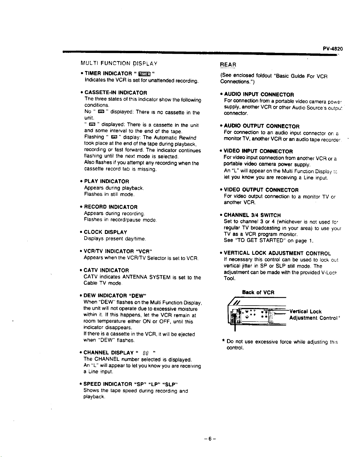
• VERTICAL LOCK ADJUSTMENT CONTROL
If necessary this control can be used to lock out
vertical jitter in SP or SLP still mode. The
adjustment can be made with the provided V-Loc_"
Tool.
Back of VCR
___-_ _'° •w Vert
, _ ical Lock
_J_,_:__._i_.___ '*" . ;b;!!;m Adjustment Control _
I
* Do not use excessive force while adjusting this
control.
-6-
DESCRIPTION OF CONTROL (CONTINUED)
The following on-screen graphics will appear automatically for a few seconds when one of the main function
buttons is pressed on the remote control or at the VCR. The channel currently tuned-in will be displayed
automatically for a few seconds when the power is first turned on, whenever the channel is changed, or when
the CHANNEL CALL Button is pressed thereafter.
STOP, EJECT, PLAY, REC, FF, REW, PAUSE, LINE, TIME, DATE, CHANNEL INDICATION, TIME COUNTER
TAPE SPEED, STANDBY SET (indicates the Standby O.T.R. mode isset), OTR (whenever StandbyOTR starts)
DEW* I
(FuNcT=oN)1
* When "DEW" appears on the "IV screen, the unitwill notoperate due to excessive
moisture within it. If this happens, let the VCR remain at room temperature, untit
this indicator disappears. If there is a cassette inthe VCR, itwill be ejected when
"DEW" appears.
Press the TIME CALL Button to show or remove the date end time from the TV
screen.
TIME COUNTER
TAPE SPEED INDICATOR
1
COUNT 1:20,47 SLP
/
et _MEMORy 1:_0,45 $PI
Press the COUNTER CALL Button to show or remove the time counter and tape
speed display.
BLANK TAPE INDICATION
If a blank (unrecorded) section of tape is encountered while in the play mode, the TV screen will change to a
solid blue field. The screen will remain blue until a recorded signal is again detected.
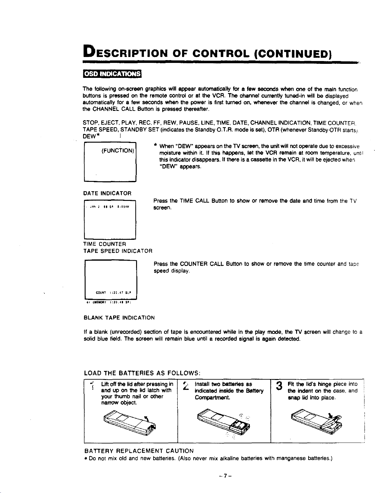
LOAD THE BATTERIES AS FOLLOWS:
Liftoff the lid after pressing in
end up on the lid latch with
your thumb nail or other
narrow object
Install two batteries as
indicated inside the Battery
Compertnent.
Fit the lid's hinge piece into
the indent on the case, and
snap lid into place.
BATTERY REPLACEMENT CAUTION
• Do not mix old and new batteries. (Also never mix alkaline batteries with manganese batteries.)
-7-
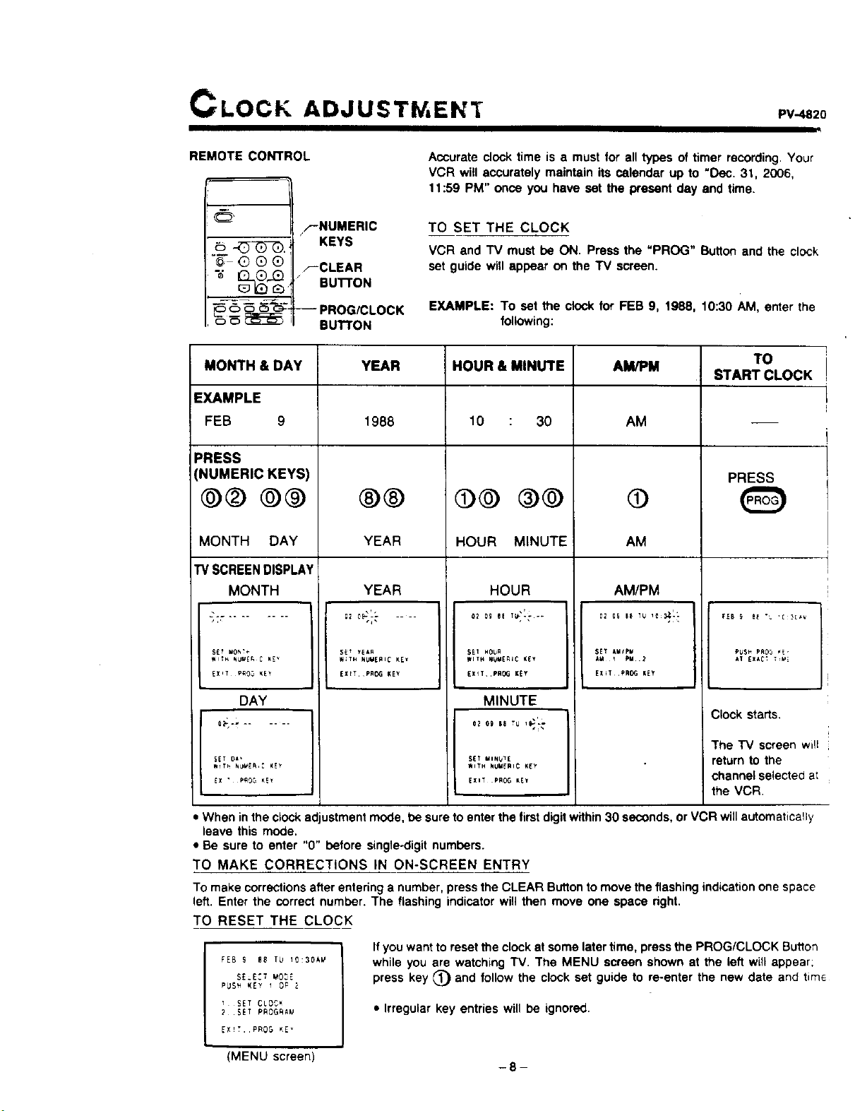
CLOCK ADJUSTW, EN'f PV- 2o
REMOTE CONTROL
F'NUMERIC
__, KEYS
"_" G Q Q ,--CLEAR
k_ [2_ Bu'n'ON
_ _ _-c_. -- PROG/CLOCK
_ _ _ BUTTON
Accurate clock time is a must for all types of timer recording. Your
VCR witl accurately maintain its calendar up to "Dec. 31, 2006,
t 1:59 PM" once you have sot the present day and time.
TO SET THE CLOCK
VCR and TV must be ON. Press the "PROG" Button and the clock
set guide wifl appear on the TV screen.
EXAMPLE: To sot the clock for FEB 9, 1988, 10:30 AM, enter the
following:
MONTH & DAY
EXAMPLE
FEB 9
PRESS
(NUMERIC KEYS
@@ ®®
MONTH DAY
TV SCREEN DISPLAY
MONTH
gET _!*,
WITH _UVE_ C _E _
DAY
SET 0_'
_X • pRO5 K!_
YEAR HOUR & MINUTE AM/PM TO
START CLOCK
1988
®®
YEAR
10 : 30
@@ ®@
HOUR MINUTE
AM
@
AM
PRESS
YEAR HOUR AM/PM
$EI NOU_
WITH NUr_l_iC _[Y
EXlL .PROG K_Y
MINUTE
S_T MINUTE
_ITH NUMERIC KEY
5E_ yEAR
W;TH NUMERIC KEI
EXITPRO¢I KEY
SET AMIp_
A_ 1 PM.2
EX_T,PR_ KEY
EXIT pROG KE_
RU$_ PR03 _E,
AT EXAC_ _VE
Clock starts,
The "IV screen will
return to the
channel selected at
the VCR.
• When inthe clock adjustment mode, be sure to enter the first digitwithin 30 seconds, or VCR will automatically
leave this mode.
• Be sure to enter "0" before single.digit numbers.
TO MAKE CORRECTIONS IN ON-SCREEN ENTRY
To make corrections after entering a number, press the CLEAR Butlon to move the flashing indication one space
left. Enter the correct number. The flashing indicator will then move one space right.
TO RESET THE CLOCK
FEB S 88 T_ 10:30k_
SE_E:T _O_E
PUS_ KEY 1 OP
SET CLOC_
2 SET PROGfiAU
EX_T. PROG _E _
(MENU screen)
Ifyou want to reset the clock at some later time, press the PROG/CLOCK Bu_lon
while you are watching TV. The MENU screen shown at the left will appear;
press key _) and follow the clock set guide to re-enter the new date and tim_
• Irregular key entries will be ignored.
-8-
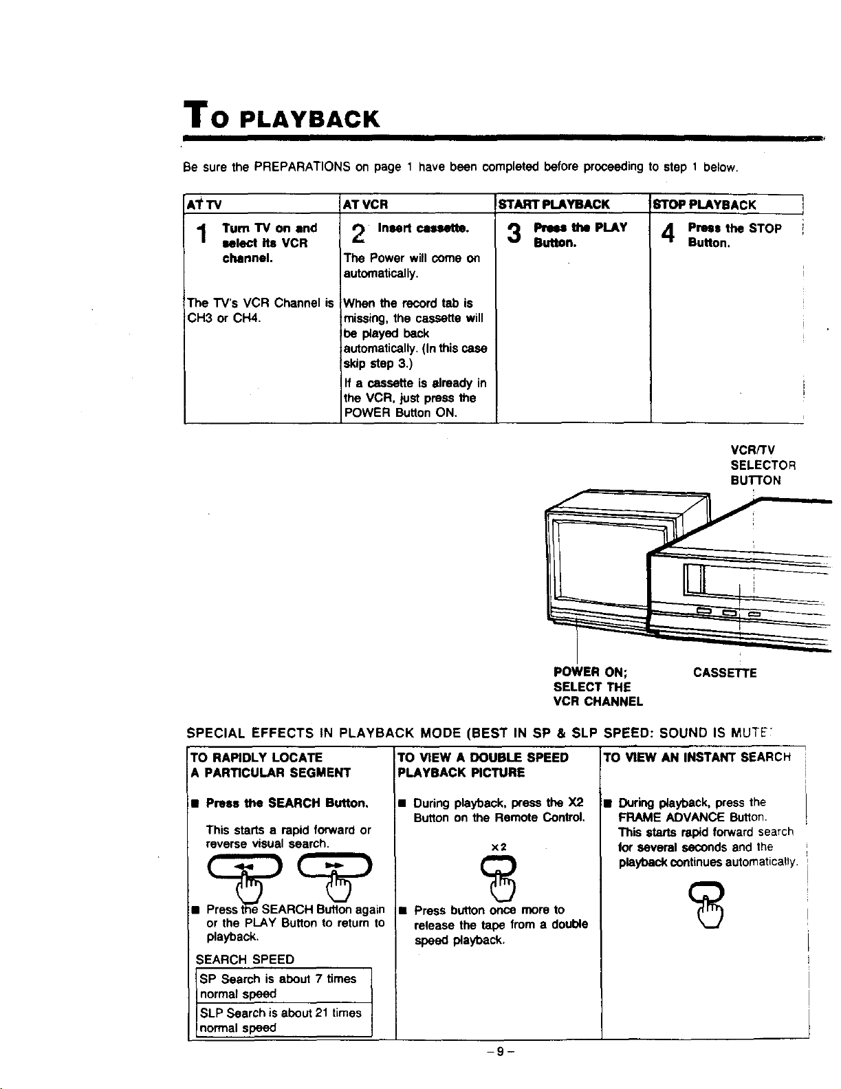
To PLAYBACK
Be sure the PREPARATIONS on page 1 have been completed before proceeding to step 1 below.
ATTV
Turn"IV on end
select its VCR
channel.
The TV's VCR Channel is
CH3 or CH4.
AT VCR
Insert cassette.
The Power will come on
automatically.
When the record tab is
missing, the cassette will
_e played back
automatically. (In this case
skip step 3.)
If a cassette is already in
the VCR, just press the
POWER Button ON.
START PLAYBACK STOP PLAYBACK
3 'LAY
Press the STOP
Button.
VCR/TV
SELECTOR
BuI"rON
POWER ON;
SELECT THE
VCR CHANNEL
CASSETTE
SPECIAL EFFECTS IN PLAYBACK MODE (BEST IN SP & SLP SPEED: SOUND IS MUTE';
TO RAPIDLY LOCATE
A PARTICULAR SEGMENT
• Prees theSEARCH Button.
This starts a rapid forward or
reverse visual search.
•
Pr_t_e SEARCH Button again
or the PLAY Button to return to
playback.
SEARCH SPEED
SP Search is about 7 times
normal speed
SLP Search is about 21 times
normal speed
TO VIEWADOUBLESPEED
PLAYBACK PICTURE
• During playback, press the X2
Button on the Remote Control.
x2
• Press button once more to
release the tape from a double
speed playback.
TO VIEW AN INSTANT SEARCH
• During playback, press the
FRAME ADVANCE Button.
This starts rapid forward search
for several seconds and the
playback continues automatically.
-9-
PV-.4820
These automatic features have been designed to simplify
PLAYBACK.
AUTO OPERATION FUNCTIONS
Cassette with record tab (for recording and playback)
Refer to page 21.
AUTO POWER ON WITH CASSETTE INSERTION
Power comes on and VCR goes into stop mode.
AUTO REWIND AT TAPE END
Tape rewinds from end automatically after playback !
or dunng fast forward tape advance.
Cassette with record tab removed (for playback only)
AUTO PLAY WITH CASSETTE INSERTION
With power ON or OFF, VCR begins playback.
AUTO REWIND AND EJECT AT TAPE END
Tape automatically rewinds from end and ejects,
VCR goes into stop mode.
STOP PLAY/STILL
BUTTON BUTTON
' /E
SEARCH BUTTONS
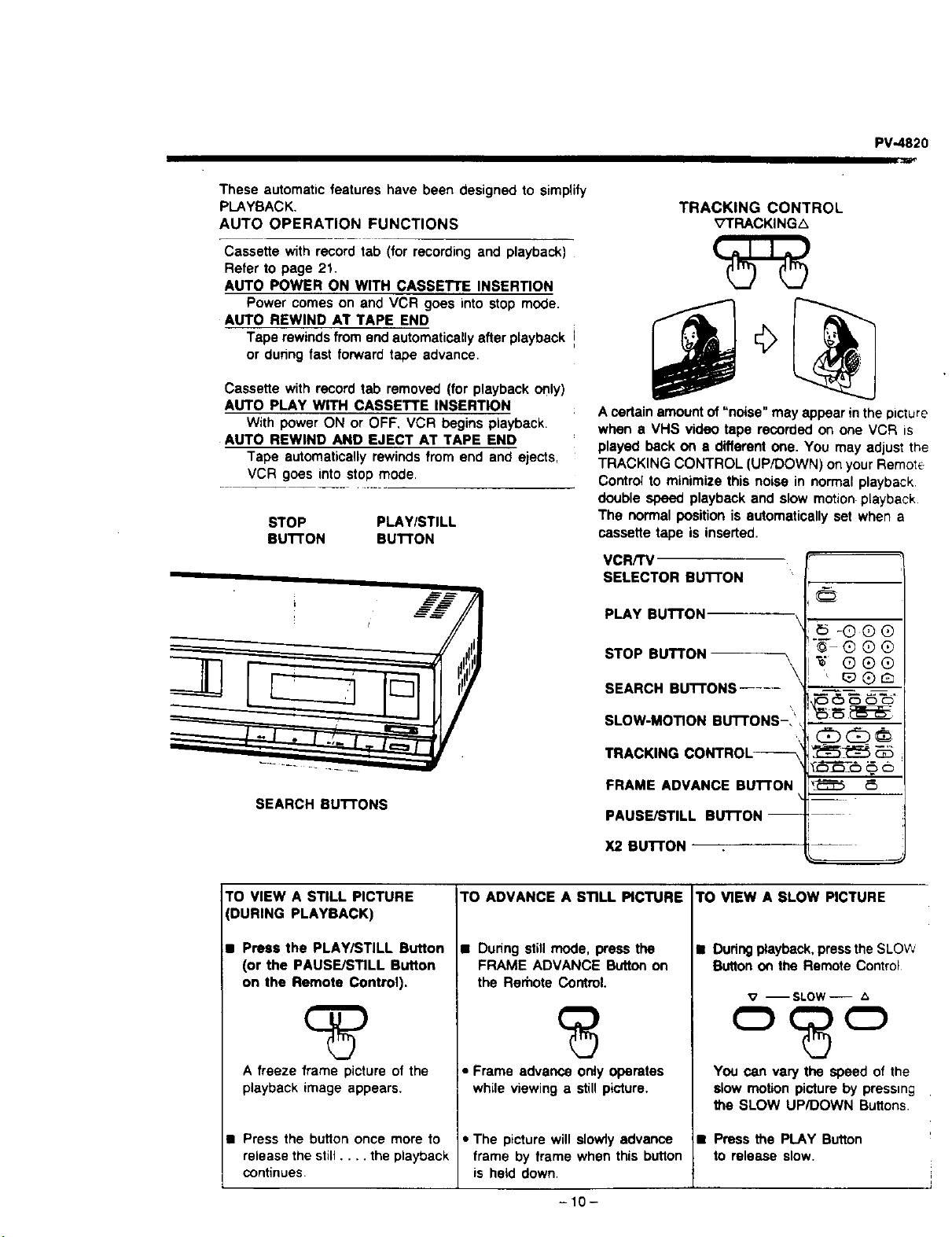
TRACKING CONTROL
_;7TRACKINGL_
A certain amount of "noise" may appear in the picture
when 8 VHS video tape recorded on one VCR =s
played back on • different one. You may adjust the
TRACKING CONTROL (UP/DOWN) on your Remote
Control to minimize this noise in normal playback
double speed playback and slow motion playback.
The normal position is automatically set when a
cassette tape is inserted.
VCR/TV
SELECTOR BUTTON
PLAY BUTTON
STOP BUTTON \
\
SEARCH BUTTONS .....
SLOW-MOTION BuI"rONS-I',
TRACKING CONTROL_
FRAME ADVANCE BUTTON
PAUSE/STILL BLrl-rON--
X2 BUTTON
@
-® ®®
"5--® ®®
®
TO VIEW A STILL PICTURE
(DURING PLAYBACK)
1• Press the PLAY/STILL Button
(or the PAUSE/STILL Button
on the Remote Control).
A freeze frame picture of the
playback image appears.
Press the bu_on once more to
release the still .... the playback
continues
TO ADVANCE A STILL PICTURE
• During still mode, press the
FRAME ADVANCE Button on
the Rerhote Control.
• Frame advance only operates
while viewing a still picture.
• The picture will slowly advance
frame by frame when this button
is held down.
TO VIEW A SLOW PICTURE
• Dudng playback, pressthe SLOW
Sutton on the Remote Control
v --SLOW--
You can vary the speed of the
slow motion picture by pressing
the SLOW UP/DOWN Buttons.
• Press the PLAY Button
to release slow.
-10-
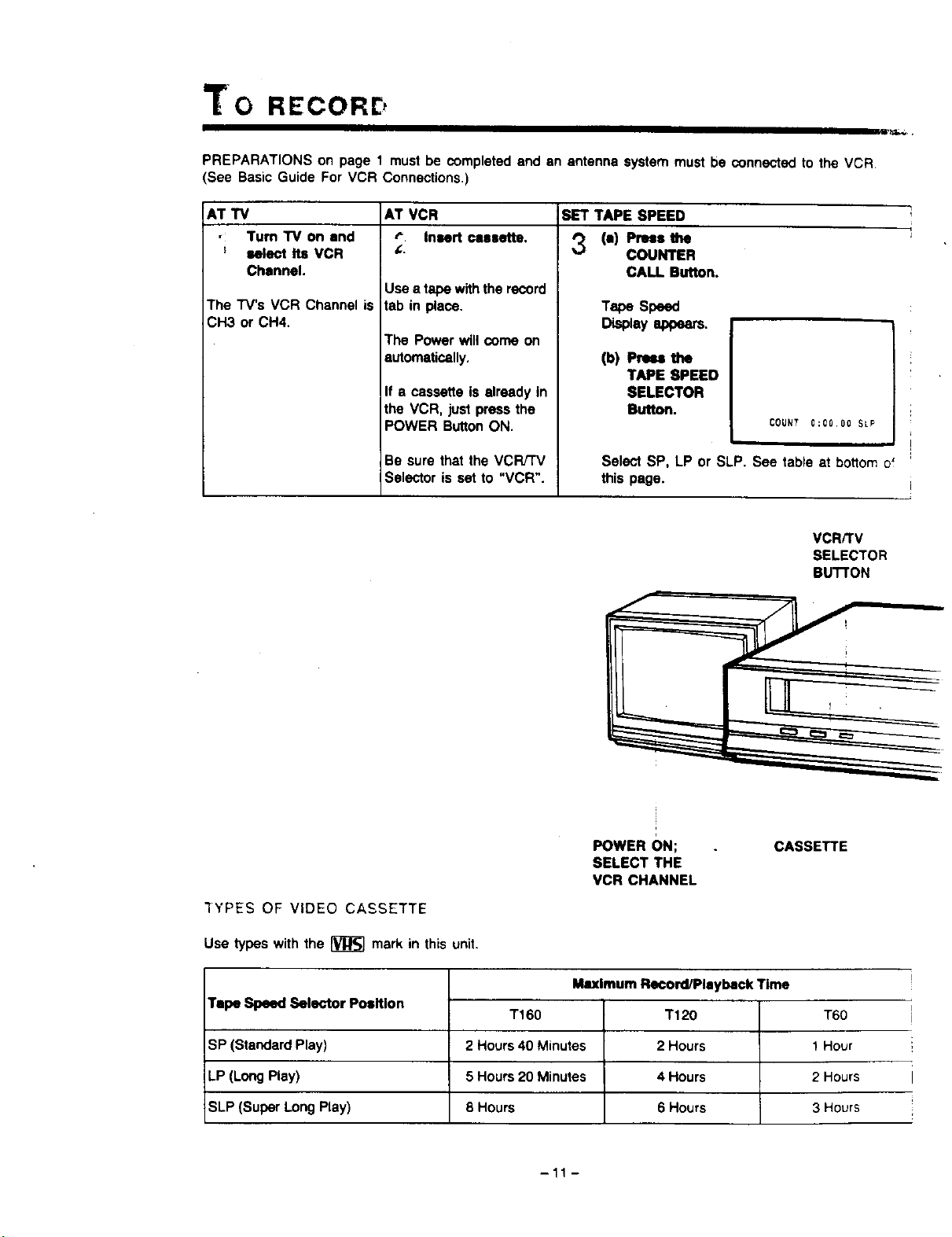
"to RECORE,
PREPARATIONS on page 1 must be completed and an antenna system must be connected to the VCR,
(See Basic Guide For VCR Connections.)
AT VCR
r" Insert cassette.
AT TV
• Turn "IV on end
; select Its VCR
Channel.
The "r'V's VCR Channel is
CH3 or CH4.
Use a tape with the record
tab in place.
The Power will come on
automatically.
If a cassette is alreadyIn
the VCR, just pressthe
POWER ButtonON.
Be sure that the VCFVTV
Selector is set to "VCR".
SET TAPE SPEED
'_ (a) Plus the
COUNTER
CALL. Button.
TapeSpeed
(b) Pr._ the
TAPE SPEED
SELECTOR
Button.
COUNT 0:00.00 SLP
Select SP, LP or SLP. See table at boHomof
this page.
VCRKV
SELECTOR
BU'I-rON
3YPES OF VIDEO CASSETTE
Use _peswiththe_r_]ma_inthisunit.
POWER ON;
SELECT THE
VCR CHANNEL
CASSETTE
Tape Speed Selector Position
SP (Standard Play)
LP (Long Play)
SLP (Super Long Play)
Maximum Rseord/Playback Time
T160 T120 T60
2 Hours 40 Minutes 2 Hours 1 Hour
5 Hours 20 Minutes 4 Hours 2 Hours
8 Hours 6 Hours 3 Hours
-11 -
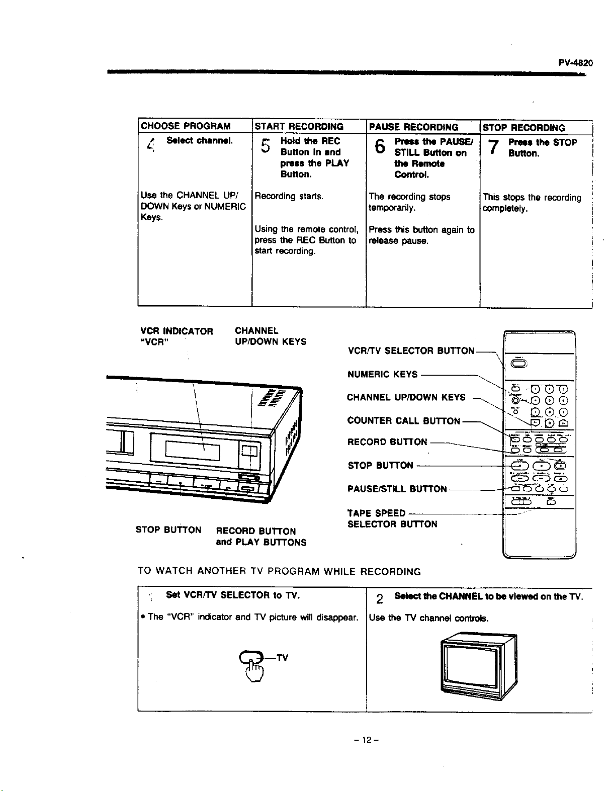
PV-4820
I1| J I
CHOOSE PROGRAM
Select channel.
Use the CHANNEL UP/
DOWN Keys or NUMERIC
Keys.
START RECORDING
_._ Hold the REC
Button In end
press the PLAY
Button.
Recording starts.
Using the remote control,
press the REC Button to
start recording.
PAUSE RECORDING
Press the PAUSE/
STILL Button on
the Remote
Control.
The recordingstops
temporarily.
Press this button again to
release pause.
STOP RECORDING
Press the STOP
Button,
This stops the recording
completely.
VCR INDICATOR
"VCR"
STOP BUTTON
CHANNEL
UP/DOWN KEYS
RECORD BUTTON
end PLAY BUTTONS
VCR/'rv SELECTOR BUTTON_-\
NUMERIC KEYS
CHANNEL UP/DOWN KEYS_
COUNTER CALL BUTTON _
RECORD BUTTON _
STOP BUTTON
PAUSE/STILL BUTTON
TAPE SPEED
SELECTOR BU't'rON
@
5 6 _ _T::S-
db (:b-®
TO WATCH ANOTHER TV PROGRAM WHILE RECORDING
• Set VCR/TV SELECTOR to TV. 2 Select the CHANNEL to be viewed on the TV.
The "VCR" indicator and TV picture will disappear. Use the "IV channel controls.
-12-
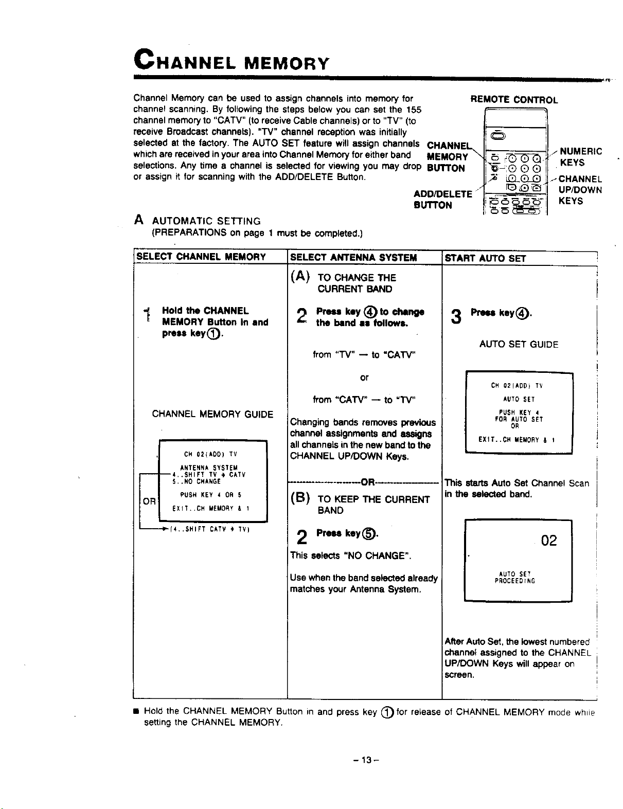
CHANNEL MEMORY
Channel Memory can be used to assign channels into memory for
channel scanning. By following the steps below you can set the 155
channel memory to "CATV" (to receive Cable channels) or to "TV" (to
receive Broadcast channels). "TV" channel reception was initially
selected at the factory. The AUTO SET feature will assign channels CHANNEL
which are received in your area into Channel Memory for either band MEMORY \
selections, Any time e channel is selected for viewing you may drop BUTTON
or assign it for scanning with the ADD/DELETE Button.
/
ADD/DELETE"
BUTTON
A AUTOMATIC SEI-rlNG
(PREPARATIONS on page 1 must be completed.)
REMOTE CONTROL
.._._.7_)_./NUMERIC
"C_;® Q O KEYS
LiZL(_ _-CHANNEL
[1__ _ _ UP/DOWN
_ _ _- KEYS
_
SELECT CHANNEL MEMORY START AUTO SET
-_ Hold the CHANNEL
MEMORY Button In end
press key(_.
CHANNEL MEMORY GUIDE
CH 02(ADO) TV
ANTENNA SYSTEM
----4..SHIFT TV @ CATV
5.,NO CHANGE
PUSH KEY 4 OR 5
OR
EXIT,.CH MEMORY A 1
•_m-I_(4,.SHIFT OAT',' ") rv)
SELECT ANTENNA SYSTEM
(A) TOCHANGETHE
CURRENT BAND
Press key (_ to change
the band as followa,
from "'i'V" -- to "CAW"
or
from "CATV" -- to "IV"
Changing bands removes previous
channel assignments and assigns
all channels in the new band to the
CHANNEL UP/DOWN Keys.
-OR-
(B) TO KEEP THE CURRENT
BAND
Preu key(_),
This selects "NO CHANGE".
Use when the band selected already
,matches your Antenna System.
Press key(_).
AUTO SET GUIDE
7
CH 02(ADD) TV
AUTO SET
PUSH KEY 4
FOR AUTO SET
OR
EXIT..CH MEMORY & 1
This starts Auto Set Channel Scan
in the selected band.
o2 i
AUTO SET
PROCEEDING
AfterAuto Set. the lowest numbered
channel assigned to the CHANNEL
UP/DOWN Keys will appear on
screen.
• Hold the CHANNEL MEMORY Button in and press key (_) for release of CHANNEL MEMORY mode whie
setting the CHANNEL MEMORY.
-13-
PV-4820
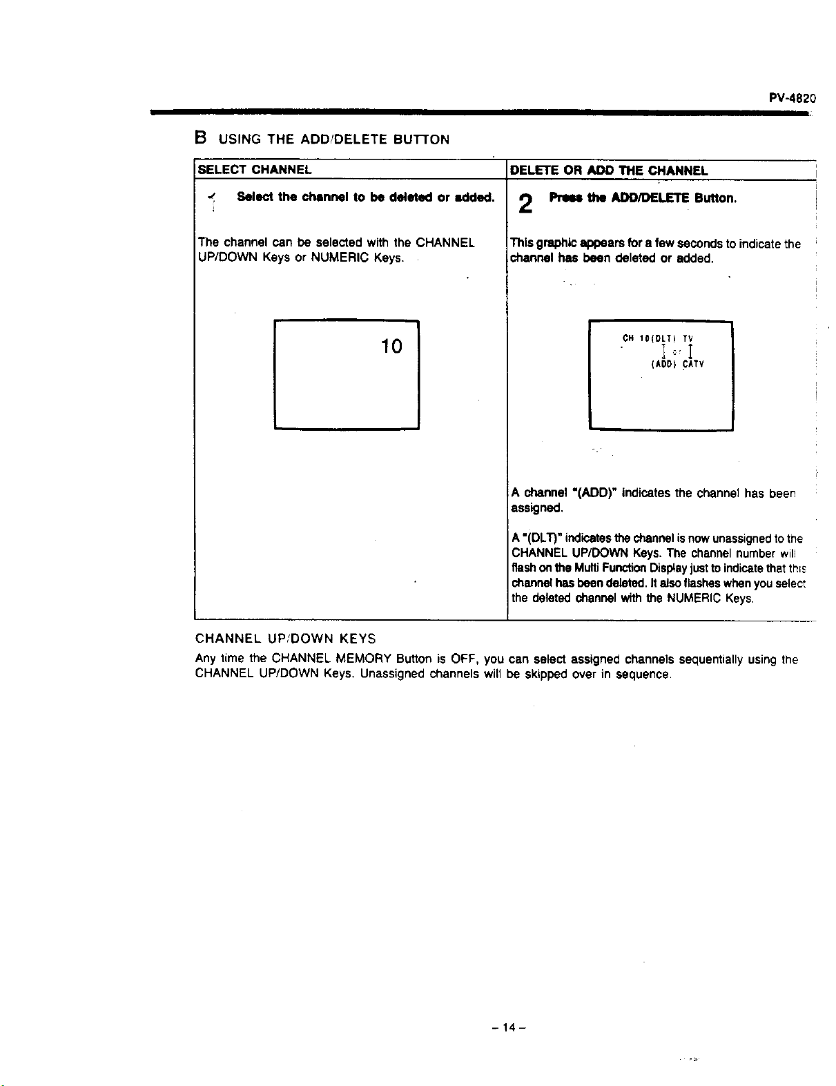
B USING THE ADD/DELETE BUTTON
SELECT CHANNEL
-" Select the channel to be deleted or added.
The channel can be selected with the CHANNEL
UP/DOWN Keys or NUMERIC Keys.
10
DELETE OR ADD THE CHANNEL
Prmm the ADD/DELETE Button.
This graphic appears for a few seconds to indicate the
channel has been deleted or added.
CH IO(DLT) TV
Io,!
(kO0) CkTV
A channel"(ADD)" indicatesthe channe{hasbeen
assigned.
A "(DLT)" indicatesthe channel isnowunassignedtothe
CHANNEL UP/DOWN Keys. The channel number will
flash onthe MultiFunctionDisplayjustto indicatethatth;s
channel hasbeen deleted. It also flasheswhenyou salect
the deleted channel with the NUMERIC Keys,
CHANNEL UP/DOWN KEYS
Any time the CHANNEL MEMORY Button is OFF, you can select assigned channels sequentially using the
CHANNEL UP/DOWN Keys. Unassigned channels will be skipped over in sequence.
-14-
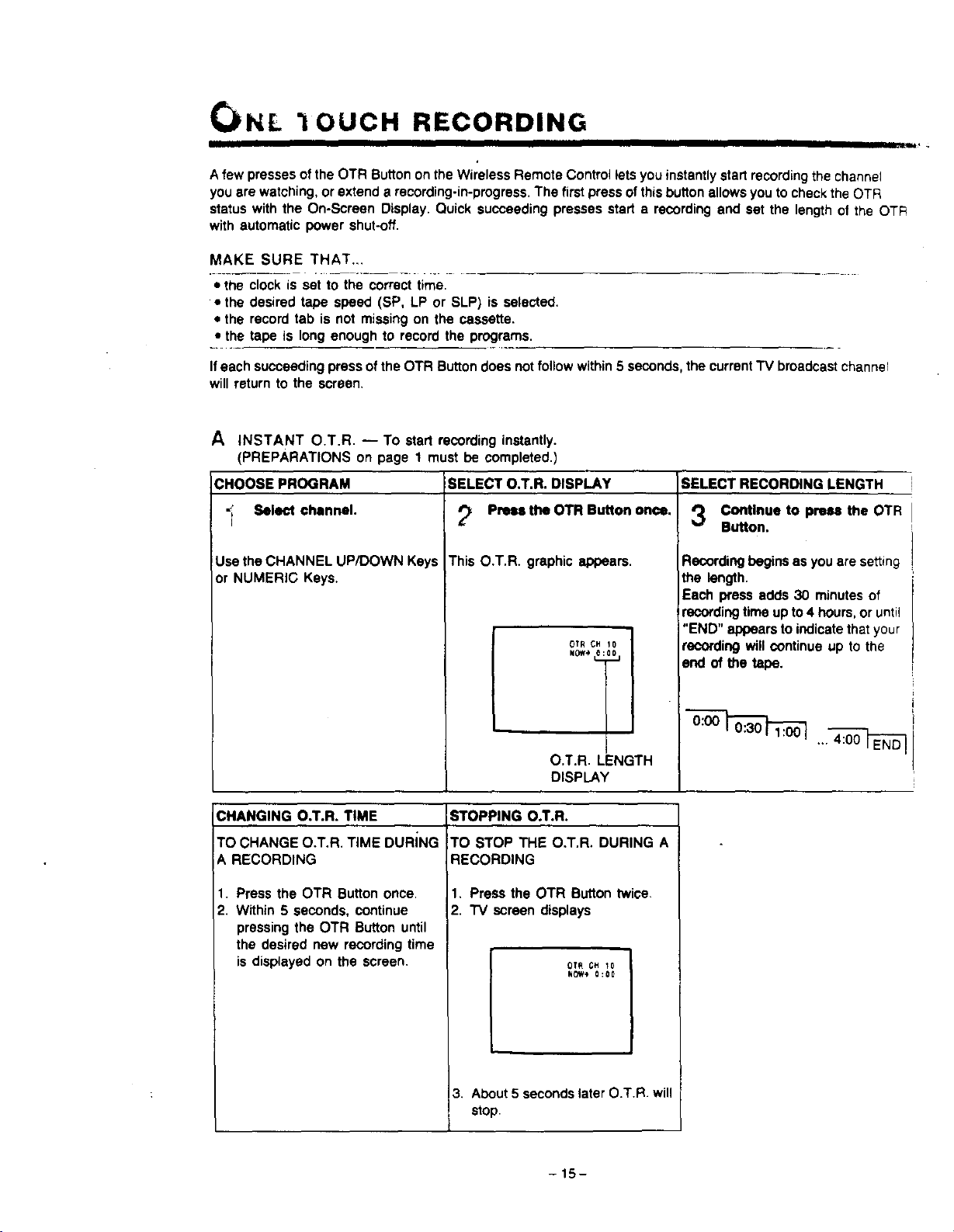
CI NL "lOUCH RECORDING
Afew presses of the OTR Button on the Wireless Remote Control lets you instantly start recording the channel
you are watching, or extend a recording-in-progress. The first press of this button allowsyou to check the OTR
status with the On-Screen Display. Quick succeeding presses start a recording and set the length of the OTR
with automatic power shut-off.
MAKE SURE THAT...
-t-h_cclock is set tothe-correct time.
• the desired tape speed (SP, LP or SLP) is selected.
• the record tab is not missing on the cassette.
• the tape is long enough to record the programs.
Ifeach succeeding press of the OTR Button does notfollow within 5 seconds, the current TV broadcast channeF
will return to the screen.
A INSTANT O.T.R. -- To start recording instantly.
(PREPARATIONS on page 1 must be completed.)
CHOOSE PROGRAM SELECT O.T.R. DISPLAY SELECT RECORDING LENGTH
Select channel. _ Press the OTR Button once. *'_ Continue to press the OTR
/ & V
Button.
This O.T.R. graphic appears.Use the CHANNEL UP/DOWN Keys
or NUMERIC Keys.
OTR CH 10
O.T.R. LENGTH
DISPLAY
Recording begins as you are setting
the length.
Each press adds 30 minutes of
recording time up to 4 hours, or until
"END" appears to indicate that your
recording will continue up to the
end of the tape.
CHANGING O.T.R. TIME
TO CHANGE O.T.R. TIME DURING
A RECORDING
1. Press the OTR Button once.
2. Within 5 seconds, continue
pressing the OTR Button until
the desired new recording time
is displayed on the screen.
STOPPING O.T.R.
TO STOP THE O.T.R. DURING A
RECORDING
1. Press the OTR Button twice.
2. "IV screen displays
OTR CH _0
NOW_* 0:00
I.
3. About 5 seconds later O.T.R. will
stop.
-15-
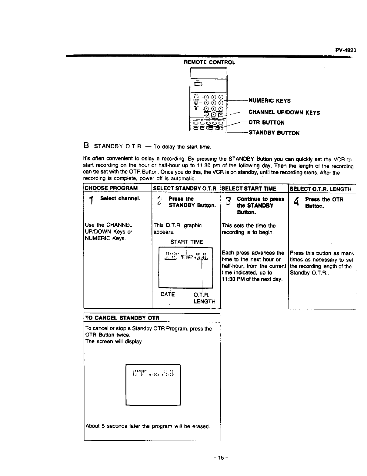
REMOTE CONTROL
PV-4820
--NUMERIC KEYS
_---CHANNEL UP/DOWN KEYS
_---OTRBUTTON
STANDBY BUTTON
B STANDBY O.T.R. -- To delay the start time.
It's often convenient to delay a recording. By pressing the STANDBY Button you can quickly set the VCR to
start recording on the hour or half-hour up to 11:30 pm of the following day. Then the length of the recording
can be set with the OTR Button. Once you do this, the VCR is on standby, untilthe recording starts. After the
recording is complete, power off is automatic.
CHOOSE PROGRAM SELECT STANDBY O.T.R. SELECT START TIME SELECT O.T.R. LENGTH
_; Press the _ Continue to press 4" Press the OTR
"_ Select channel. _" STANDBY Button. the STANDBY Button.
Use the CHANNEL
UP/DOWN Keys or
NUMERIC Keys.
This O.T.R. graphic
appears.
START TIME
STANOSYI CM10
I
, !
DATE O.T.R.
LENGTH
Button.
Thissets the time the
recordingis to begin.
Each press advances the
time to the next hour or
half-hour, from the current
time indicated, up to
11:30 PM of the next day.
Press this button as man_
times as necessary to set
the recording length ofthe
Standby O.T.R..
TO CANCEL STANDBY OTR
To cancel or stop e Standby OTR Program, press the
OTR Button twice.
The screen will display
STkND_Y C_ 10
SU I0 900J _ 0:00
About 5 seconds later the program will be erased.
-16-

TIMER RECORDING
Your VCR will begin 8 separate unattended recordings any time within one month of the time you set them
Whenever a program number is vacant you can schedule a recording for some day ahead or even a full series
of recordings, with the time and channel you desire. A series recording starts everyday or on the same day of
each week, automatically adding recording after recording up to the end of a tape;
MAKE SURE THAT...
• PREPARATIONS on page 1 have been completed.
• the clock is set to the correct time.
• the desired tape speed (SP, LP or SLP) is selected.
• the record tab is not missing on the cassette.
• the tape is long enough to record the programs.
If no selections ere entered within 30 seconds,
the programming screen will return to the menu
screen.
SELECT THE MENU SCREEN SELECT THE PROGRAM NUMBER FOLLOW THE PROGRAM GUIDE
AND PROGRAM SET MODE ON TV SCREEN
Press the PROG Button. t . Press key_). 4 Press the NUMERIC Keys.
r Press key_).
JkN 2 BS SA |:0SAM
SELECT MOOE
PUSH KEY 1 OR 2
1..SET CLOCK
2.SET PAOGRA_
EX_T. PROG KEY
(MENU screen)
.... :....: ....
.... :....;..
.... :....:..
5 .... :.. °.: ....
.... :....:..
SELECT PnO¢ mO_',Ji, r
-PROGRAM screen)
For each prompt enter the
information desired with the
NUMERIC Keys,
See example on the following
page.
SET NEXT PROGRAM
Press key (_ or press the PROG Button
to return to the broadcast channel.
I 3 _:30PI0:00P 10
2 .... : .... : ....
3 .... :o° °.: ....
4 .... :°° °°: ....
S .... :.. °.: ....
6 .... •........
T .... :°o °°: ....
$ .... : ........
EXIT¸ .HI_ KEY
SET THE TIMER
6
Press the POWER Button to OFF.
• TIMER indicator " _" appears.
• Ifthe record tab ismissing, tape will be ejected
and the CASSETTE-IN Indicator " r_ " and
• _ " will flash to alert you.
AFTER THE TIh_Er_ RECORDING HAS TAKEN PLACE
• Press the POWER Button to ON to return your VCR to normal operation.
REMOTE CONTROL
e_ .®®@
-_- ®®®'
"o ®®®
CD C_ 0 CD C_
-NUMERIC
KEYS
CLEAR
BUTTON
PROG
BUTTON
VCR FRONT PANEL
=m c=
L
POWER BUTTON
TIMER INDICATOR
-17-
PV-4820
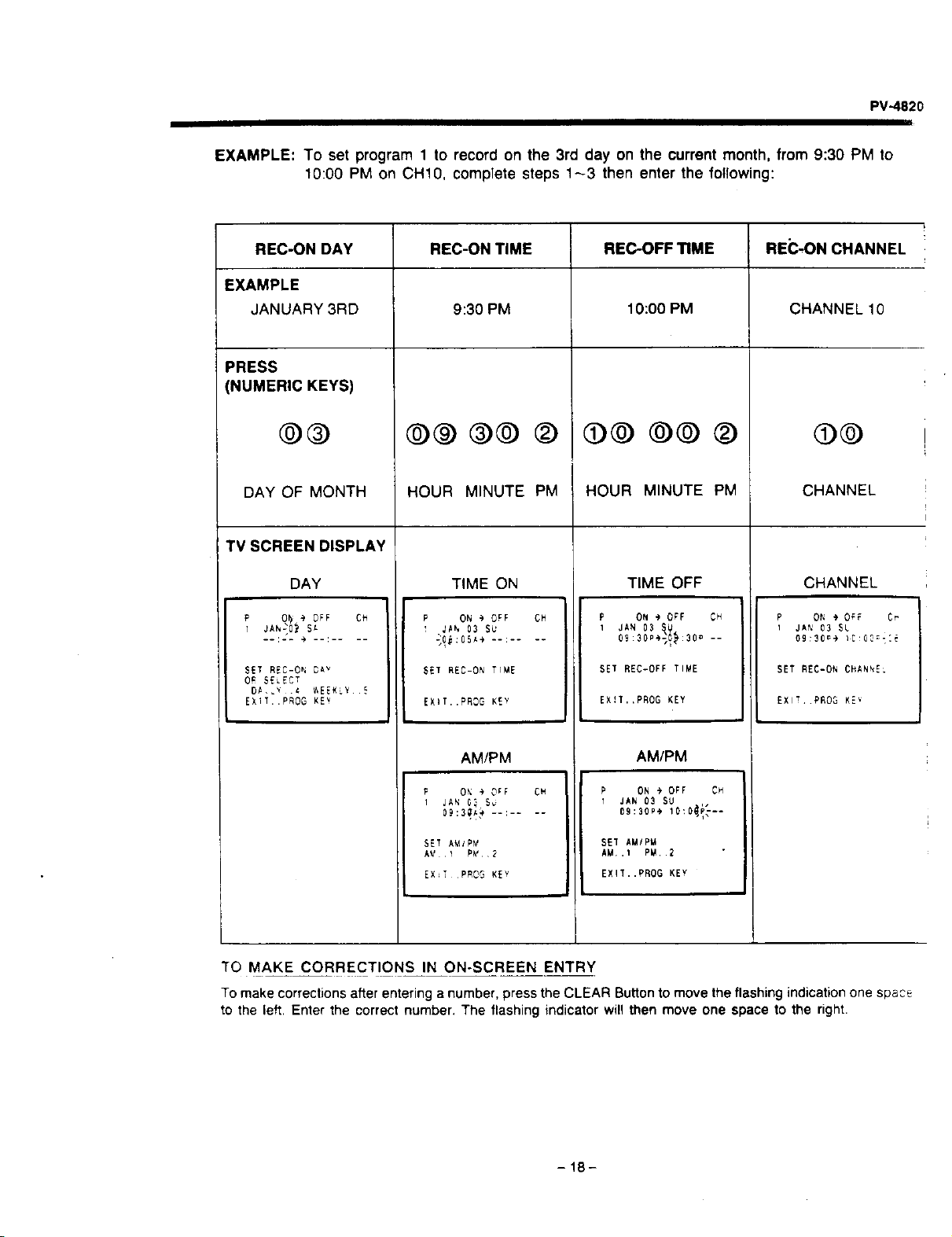
EXAMPLE: To set program 1 to record on the 3rd day on the current month, from 9:30 PM to
10:00 PM on CH10, complete steps 143 then enter the following:
REC-ON DAY
EXAMPLE
JANUARY3RD
PRESS
(NUMERIC KEYS)
@®
DAY OF MONTH
REC-ON TIME
9:30 PM
@® ®@
REC-OFF TIME REC-ON CHANNEL
10:00 PM CHANNEL10
©©
CHANNEL
HOUR MINUTE PM HOUR MINUTE PM
TV SCREEN DISPLAY
DAY TIME ON CHANNEL
P ON _ OFF CH
_Ah 03 SU
P O_ _ OFF CH
l JAh20_SA
SET REC-ON DAV
O_ SELEC T
DA _ .{ _EEKLY S
EXIT..PROG KEv
SET REC-ON TIME
TIME OFF
P ON @ OFF CH
1 JAN 03 _U
09:30P*_:30 --
SET REC-0FFTI_E
EX!T..PROG KEY
AM/PM
P ON @ OFF CH
I JAN 03 SU
09:_0.* 10:0_i_--
SET AMIP_
AM,.I PM..2
EXIT..PROG KEY
EXIT..PROG KEY
AM/PM
i JAN _ 5_
o9:30_)--: ....
P ON + OFF Cr
I JAN 03 SL
09:30_÷ IC 0C,;_:_
SET REC-0N CHANNEL
EXl!, PR03 KE_
SET AMYPY
EX_TPROG KEY
TO MAKE CORRECTIONS IN ON-SCREEN ENTRY
To make corrections after entering a number, press the CLEAR Button to move the flashing indication one space
to the left. Enter the correct number. The flashing indicator will then move one space to the right.
-18-
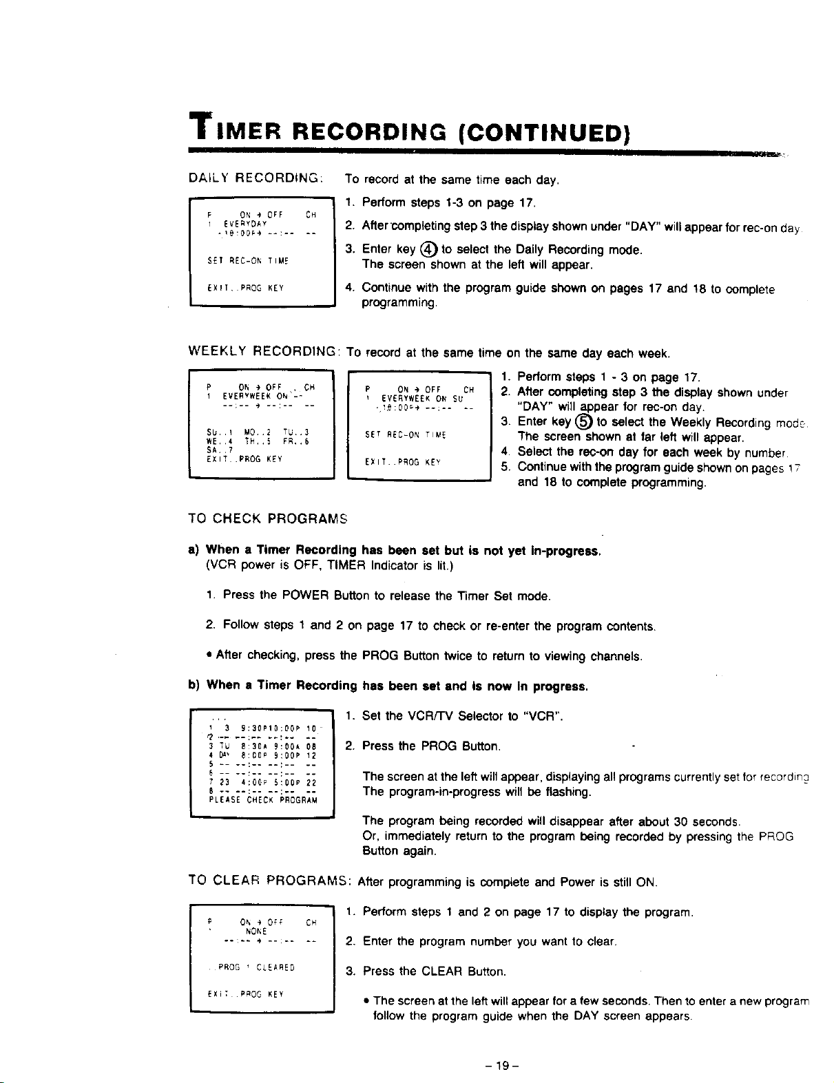
TIMER RECORDING (CONTINUED)
DALLY RECORDING:
P ON • OFF CH
i EVERYDAY
SET REC-ON TIME
EX_T, PROG KEY
To record at the same time each day.
1. Perform steps 1-3 on page 17.
2. After completing step 3 the display shown under "DAY" willappear for rec-on day
3. Enter key (_ to select the Daily Recording mode.
The screen shown at the left will appear.
4. Continue with the program guide shown on pages 17 and 18 to complete
programming.
WEEKLY RECORDING: To record at the same time on the same day each week.
P ON _ OFF , CH
1 EVERVWEEK ON'-:
SU..1 M0 E TU 3
WE,,4 TH,,5 FR,,E
SA. ,7
EXIT .PROG KEY
P ON @ OFF CH
EVERYWEEK ON SU
SET REC-ON TIME
EXIT PROG KEY
1. Perform steps 1 - 3 on page 17.
2. After completing step 3 the display shown under
"DAY" will appear for rec-on day.
3. Enter key _) to select the Weekly Recording mode
The screen shown at far left will appear.
4. Select the rec-on day for each week by number
5. Continue with the program guide shown on pages ! ;
and 18 to complete programming.
TO CHECK PROGRAMS
e) When a Timer Recording has been set but ts not yet In-progress.
(VCR power is OFF, TIMER Indicator is lit.)
1. Press the POWER Button to release the Timer Set mode.
2. Follow steps 1 and 2 on page 17 to check or re-enter the program contents.
• After checking, press the PROG Buttontwice to return to viewing channels.
b) When • Timer Recording has been set end Is now In progress.
1 3 9:30P10:OOP 10
3 TU 8:30A 9:00A 0S
4 _ E:00_ 9:00P 12
5 .... :.... : ....
E .. .... : ....
7 23 4;00P 5:00P 22
6 .... :__ •
PLEASE CHECK PROGRAM
1. Set the VCR/'I'V Selector to "VCR".
2. Press the PROG Button.
The screen at the left will appear, displaying all programs currently setfor recordin_
The program-in-progress will be flashing.
The program being recorded will disappear after about 30 seconds.
Or, immediately return to the program being recorded by pressing the PROG
Button again.
TO CLEAR PROGRAMS: After programming is complete and Power is still ON.
P O_ _ OFF
NO_E
PROG i CLEARED
EXiT P_OG KEY
I.
CFY
2.
3.
Perform steps 1 and 2 on page 17 to display the program.
Enter the program number you want to clear.
Press the CLEAR Button.
• The screen at the left will appear for a few seconds. Then to enter a new program
follow the program guide when the DAY screen appears.
-19-
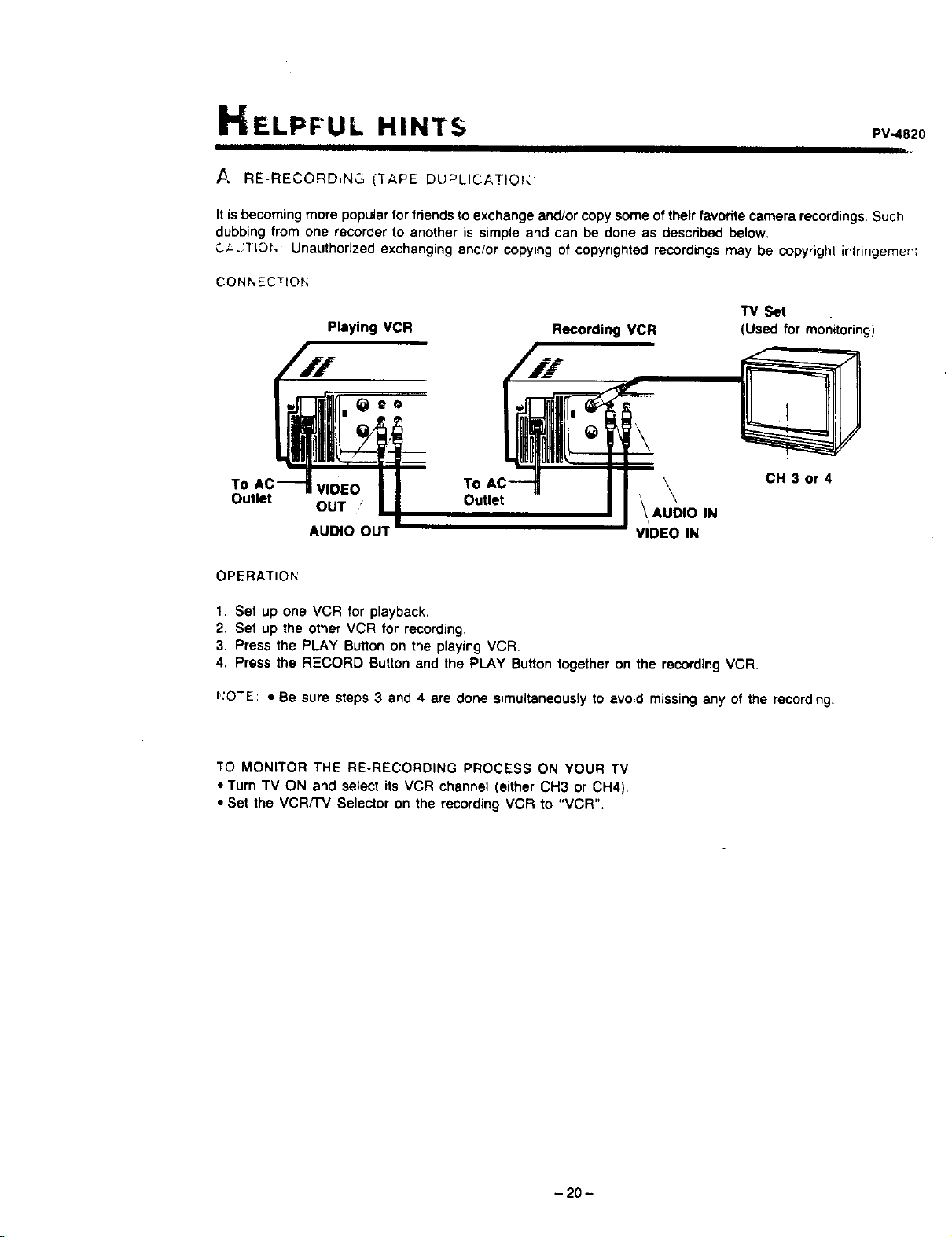
ELPFUL HINTS PV4820
/5 RE-RECORDING ("[APE DUPLICAT O _:
It is becoming more popular forfriends to exchange and/or copy some oftheir favorite camera recordings. Such
dubbing from one recorder to another is simple and can be done as described below.
C;,UiIO_', Unauthorized exchanging and/or copying of copyrighted recordings may be copyright infringemen;
CONNECTION
"1_ Set
Playing VCR Recording VCR (Used for monitoring)
To VIDEO To , \
Outlet OUT " \ AU_DIO IN
AUDIO OUT VIDEO IN
CH 3 or 4
OPERATION
1. Set up one VCR for playback,
2. Set up the other VCR for recording.
3. Press the PLAY Sutton on the playing VCR.
4. Press the RECORD Button and the PLAY Button together on the recording VCR.
_:OTE: • Be sure steps 3 and 4 are done simultaneously to avoid missing any of the recording.
TO MONITOR THE RE-RECORDING PROCESS ON YOUR TV
• Tum TV ON and select its VCR channel (either OH3 or CH4).
• Set the VCR/'rv Selector on the recording VCR to "VCR".
- 20 -
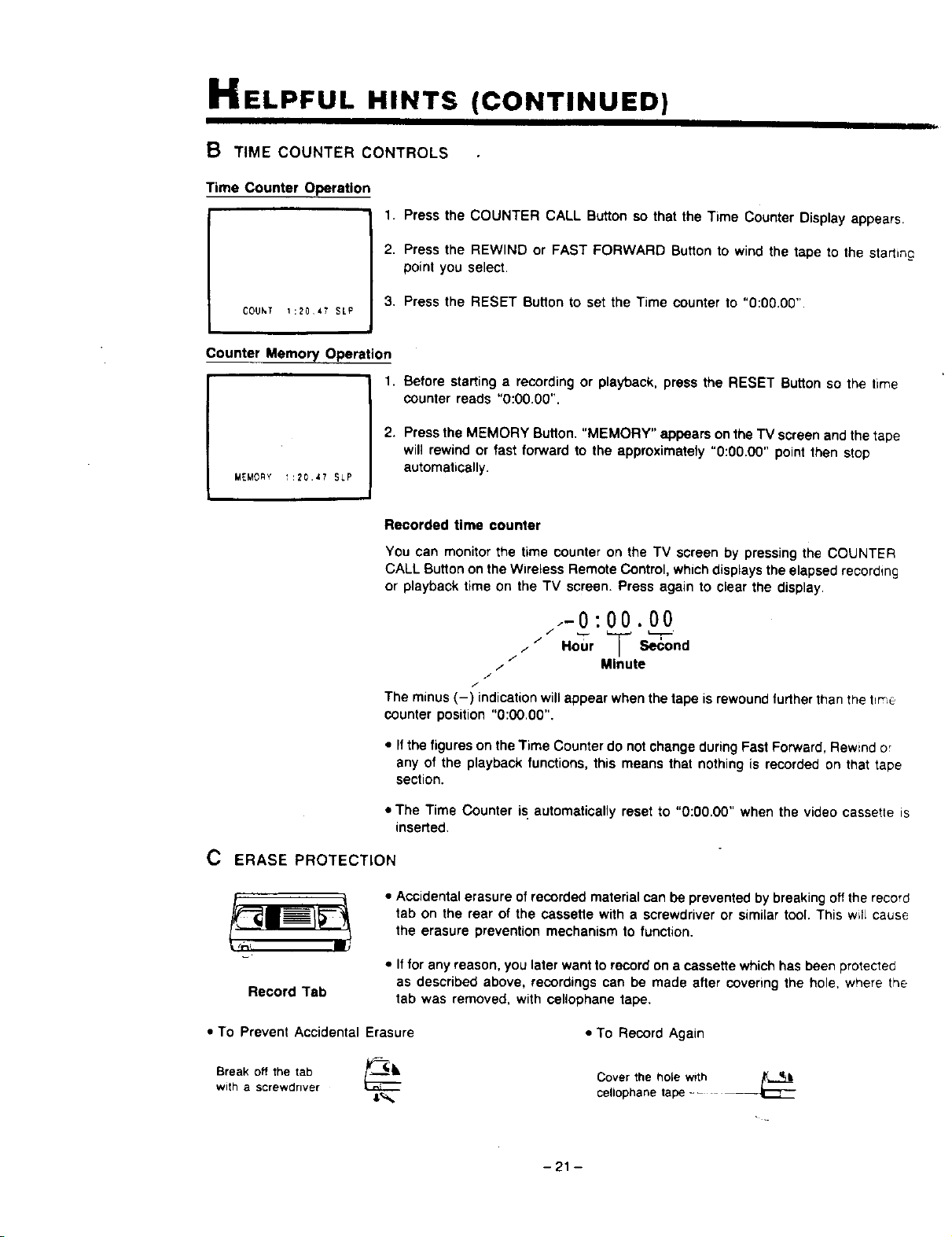
HELPFUL HINTS
B TIME COUNTER CONTROLS
Time Counter Operation
COUhT 1:2047 SLP
(CONTINUED)
1. Press the COUNTER CALL Button so that the Time Counter Display appears.
2. Press the REWIND or FAST FORWARD Button to wind the tape to the starting
point you select.
3, Press the RESET Button to set the Time counter to "0:00.00".
Counter Memory Operation
1. Before starting a recording or playback, press the RESET Button so the time
counter reads "0:00.00".
MEMORY 1:20.47 SLP
2. Press the MEMORY Button, "MEMORY" appears on the TV screen and the tape
will rewind or fast fonNard to the approximatety "0:00.00" point then stop
automatically.
Recorded time counter
You can monitor the time counter on the TV screen by pressing the COUNTER
CALL Button on the Wireless Remote Control, whichdisplays the elapsed recording
or playback time on the TV screen. Press again to clear the display.
.-0:00.00
/ Hour _--Second
//
/ Minute
J
/
The minus (-) indication will appear when the tape is rewound furtherthan the t_me
counter position "0:00.00".
• Ifthe figures on the Time Counter do not change during Fast Forward, Rewind or
any of the playback functions, this means that nothing is recorded on that tape
section.
• The Time Counter is automatically reset to "0:00.00" when the video cassette is
inserted.
C ERASE PROTECTION
• Accidental erasure of recorded material can be prevented by breaking off the record
tab on the rear of the cassette with a screwdriver or similar tool. This will cause
the erasure prevention mechanism to function.
Record Tab
• Iffor any reason, you later want to record on a cassette which has been protected
as described above, recordings can be made after covenng the hole, where the
tab was removed, with cellophane tape.
• To Prevent Accidental Erasure
Break off the tab r_.._lk
with a screwdriver
• To Record Again
Cover the hole with /_L_
cellophane tape --
-21 -
PV-4820
D NOTES ON OPERATIONS
TO GET STARTED
• With cable connections, numbers selected to recewe
specific channels may differ from those for antenna
connections. Refer tothe separate Basic Guide for VCR
Connections (or your cable service information).
• If the reception on all VHF channels is unsatisfactory you
may need to re-tune your "IV set.
CLOCK ADJUSTMENT
• Enter the first digit to set the month within 30 seconds of
the appearance of the clock set guide. Otherwise. the
program you were watching will retum to the screen. If
this happens, press the PROG/CLOCK Button and start
TO RECORD
• With manual recordings, if the tape end is reached during
recording, the VCR automat_stly rewtnds and ejects the
tape and then shuts itseff OFF.
• It is possible to change the Tape Speed Selection while
you are actually receKling but there will be a momentary
distortion when the tape is played back over the points
where the tape speed change occurred.
• After the VCR has been in pause for 5 minutes itwi!l stop
automatically for tape and video head protection
ONE TOUCH RECORDING
• Duhnga One Much Recording,press the OTR Button
again
• The letters for day of the week will automatically appear
when you have entered both digits for the year.
• If the day digit entered does not match the calendar, it
will advance to the first day of the nest month (for
example, "FEB 29 89' wil_advance to "MAR 01 89").
• If you press the PROG Button while the clock set guide
"-....... :. " appears, the TV screen will return to the
program you were watching.
once to see the remaining recording tirne overlay
• If the record tab is missing on the cassette, it will be
ejected when you press the OTR BUtCh or STANDBY
Button.
• If the preset time for a Timer Recording comes up during
a One Touch Recording, the One Touch Recording wd
take pnority.
TIMER RECORDING
TO PLAYBACK
• During search playback, horizontal noise bars will appear
on the TV screen
• After the VCR is in the pause or slow mode for 5 minutes
it will stop automatically for tape and video head
protection.
• Special effects playback can be activated during playback
Of the tapes recorded in SP or SLP speed. Tapes
recorded in LP mode can also be viewed in special effects
playback, but the picture may be completely snowy
• Timer Recording may not be bertormed or continued if a
power interruption of more than about 2 minutes occurs
before or during Timer Recording, even if power resumes
thereafter.
• If the start times of 2 preset programs overlap, the preset
time of the lower numbered program will have priority
RE-RECORDING
• For technical reasons, the quality of the dubbed tape will
not be as good as the original.
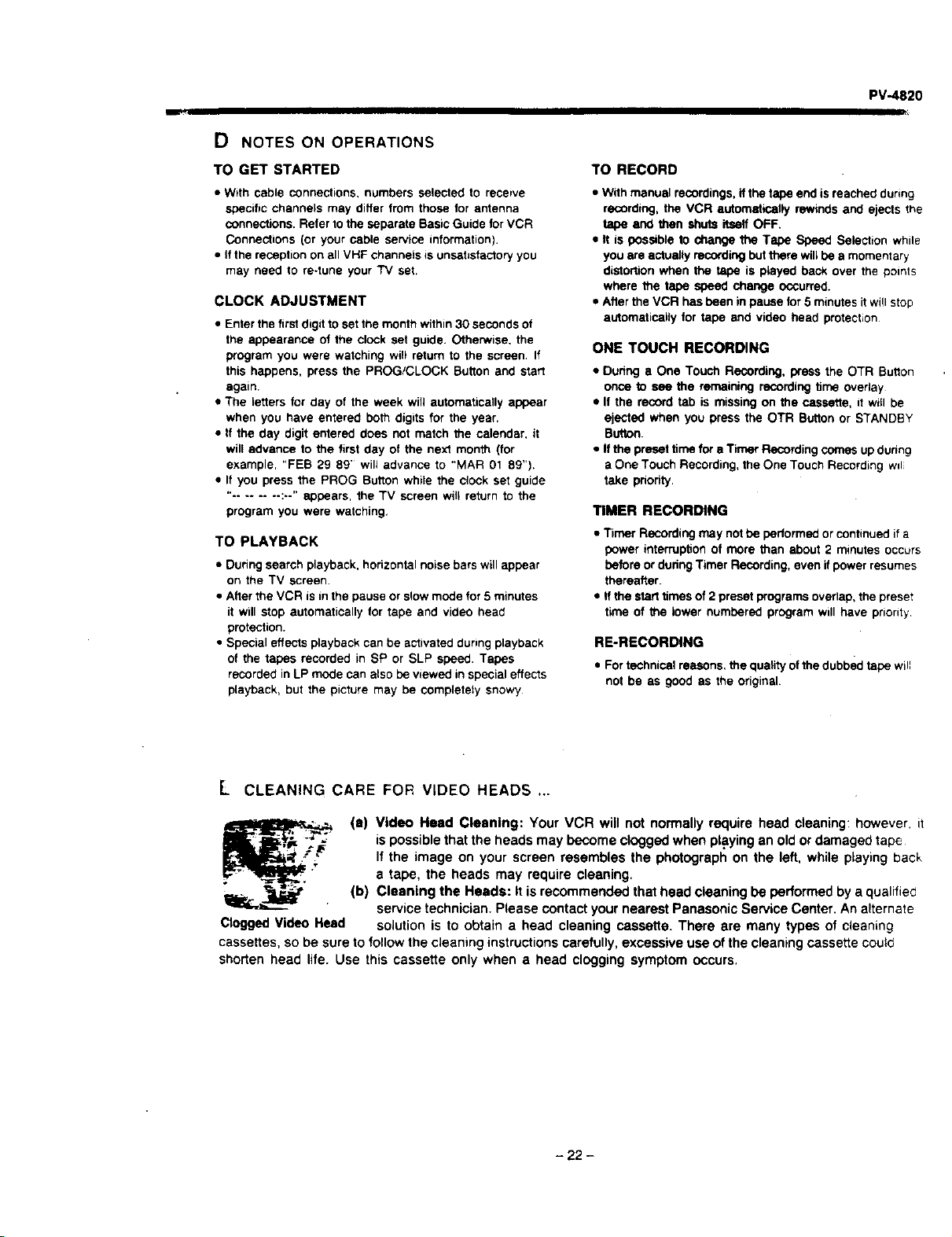
L CLEANING CARE FOR VIDEO HEADS .,.
Clogged Video Head
(s) Video Head Clsenlng: Your VCR will not normally require head cleaning: however, if
ispossible that the heads may become clogged when playing an old or damaged tape
If the image on your screen resembles the photograph on the left, while playing back
a tape, the heads may require cleaning.
(b) Cleaning the Heads: It is recommended that head cleaning be performed by a qualified
service technician. Please contact your nearest Panasonic Service Center. An alternate
solution is to obtain a head cleaning cassette. There are many types of cleaning
cassettes, so be sure to follow the cleaning instructions carefully, excessive use ofthe cleaning cassette could
shorten head life. Use this cassette only when a head clogging symptom occurs.
- 22 -
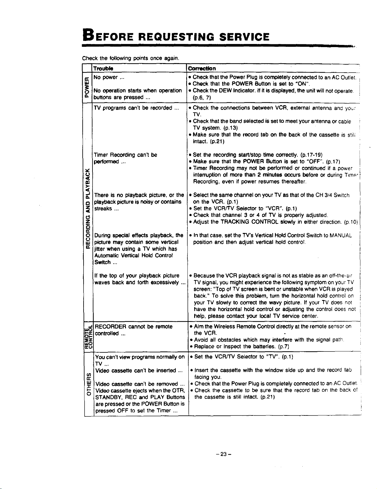
BEFORE REQUESTING SERVICE
;heck the following points once again.
Trouble Co_n
_: NO power ... • Check that the Power Plug is completely connected to an AC Outlet
gJ • Check that the POWER Button is set to "ON".
_O No operation starts when operation • Check the DEW Indicator. If it isdisplayed, the unit will not operate
=- buttons are pressed ... (p=6, 7)
I"V programs can't be recorded ... • Check the connections between VCR, external antenna and you:
TV.
• Check that the band selected isset to meet your antenna or cable
TV system. (p.13)
• Make sure that the record tab on the back of the cassette is stil;
(3
Z
8
Timer Recording can't be
)ertormed ...
There is no playback picture, or the
playback picture is noisy or contains
streaks ...
During special effects playback, the
)icture may contain some vertical
itter when using a "IV which has
Automatic Vertical Hold Control
Switch ...
If the top of your playback picture
waves back and forth excessively ...
intact. (p.21)
• Set the recording start/stop time correctly. (p.17-19)
• Make sure that the POWER Button is set to "OFF". (p.17)
• Timer Recording may not be performed or continued if a power
interruption of more than 2 minutes occurs before or during Time,
Recording, even if power resumes thereafter.
• Select the same channel on your"IV as that ofthe CH 3/4 Switch
on the VCR. (p.1)
• Set the VCR/TV Selector to "VCR". (p,1)
• Check that channel 3 or 4 of TV is properly adjusted.
• Adjust the TRACKING CONTROL slowly in either direction. (p.10)
• In that case, set the TV's Vertical Hold Control Switch to MANUAL
position and then adjust vertical hold control.
• Because the VCR playback signal is not as stable as an ofl-the-a_r
TV signal, you might experience the following symptomon your TV
screen: "Top of TV screen is bent or unstable when VCR is played
back." To solve this problem, turn the horizontal hold control on
your TV slowly to correct the wavy picture. If your TV does not
have the horizontal hold control or adjusting the control does not
help, please contact your local TV service center.
=_ RECORDER cannot be remote • Aim the Wireless Remote Control directly at the remote sensor on
_-=: controlled the VCR.
OI- ""
_== • Avoid all obstacles which may interfere with the signal path
LuO
=:u • Replace or inspect the batteries. (p.7)
iYou can't view programs normally on • Set the VCR/TV Selector to "TV". (p.1)
"l"V ...
Video cassette can't be inserted ...
Video cassette can't be removed ...
Video cassette ejects when the OTR
STANDBY, REC and PLAY Buttons
are pressed or the POWER Button is
)ressed OFF to set the Timer ...
03
n-
S
• insert the cassette with the window side up and the record tab
facing you.
• Check that the Power Plug is completely connected to an AC Outlet
• Check the cassette to be sure that the record tab on the back of
the cassette is still intact. (p.21)
- 23 -
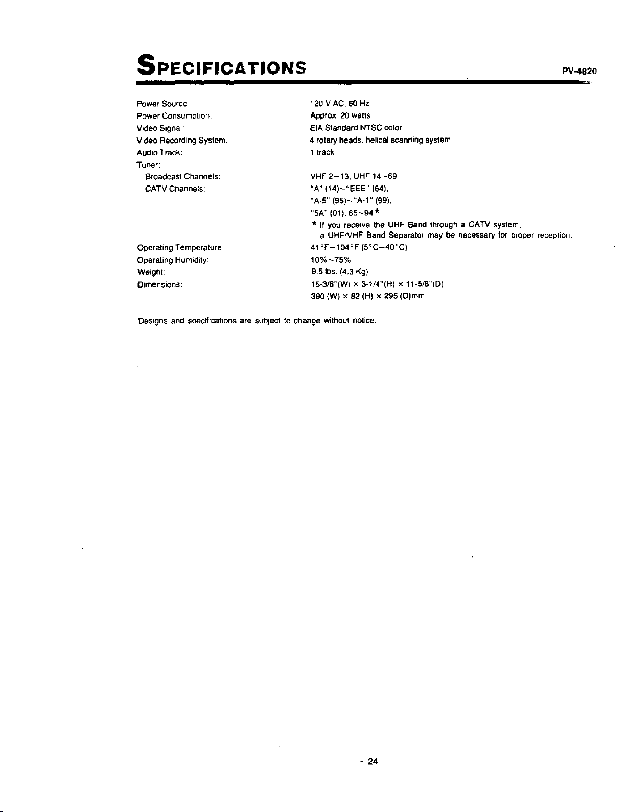
SPECIFICATIONS pv482o
Power Source:
Power Consumption
Video Signal:
Video Recording System:
Audio Track:
Tuner:
Broadcast Channels:
CATV Channels:
Operating Temperature:
Operating Humidity:
Weight:
Dimensions:
120 V AC. 60 Hz
Approx. 20 watts
EIA Standard NTSC color
4 rotary heads, helical scanning system
1track
VHF 2-13, UHF 14_69
"A" (14)-"EEE" (64),
"A-5" (95)_"A-1" (99),
"SA" (01), 65_94"
* tt you receive the UHF Band through a CATV system,
a UHFNHF Band Separator may be necessary for proper reception
41_F--104°F (5_C--40"0)
10% --75%
9.5 Ibs (4.3 Kg)
15-3/8"(W) x 3-1/4"(H) x 11-5/8"(D)
390 (W) x 82 (H) x 295 (D)mm
Designs and specifications are subject to change without notice,
- 24 -
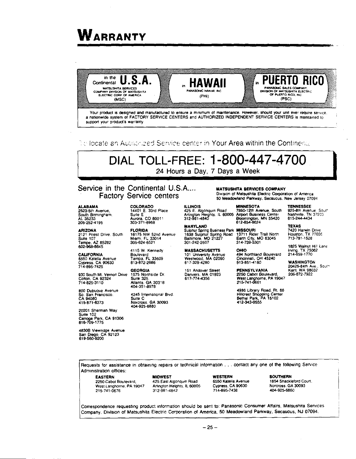
WARRANTY
I IIII III =,
intheU.S.A. inHAWAII PUERTORICI
Continental
MATSU,_'dlTA _:_RVI_ S PANA_0_ $_S COMPANy
CO_IpANV _VIS_ON OF MATSUSHIT_ P/QNASONIC HAWAII INC DIVI_ OF II#_TSU,_HITA ELECTRfC
ELECTRICCO'OPOFAMERICA (PHi) OF_=UeRTORICO._C
(MSC}
Your product iS designed and manufactured to ensure a mlnJmum of maintenance. However, sho_JIdyour unit ever require service.
a nationwide system of FACTORY SERVICE CENTERS and AUTHORIZED INDEPENDENT SERVICE CENTERS is maintained to
supporl your product's warranty
- _ r_ ...... _ _ ., .-._.locate _, A_,_ ..... e_, Sc _.._cen_-_r in Your Area within the Contine-i,
I
DIAL TOLL-FREE: 1-800-447-4700 i24 Hours a Day, 7 Days a Week
Service in the Continental U.S.A ....
Factory Service centers
ALABAMA
2523-5th Avenue,
South Birmingham.
AL 35233
205-252-4195
MATSUSHITA SERVICES COMPANY
Division of Matsushita Electric Corpofstion of America
50 Meadowland Parkwsy, Secaucus, New Jersey 07094
COLORADO ILLINOIS MINNESOTA TENNESSEE
14401 E 33rd Place 425 E. Alglonquin Road 7860-12th Avenue, South 925-8th Avenue Sour_
Suite E Adington FI Nashvil}e, TN 37203eights, IL 60005 Aifpo_ Business Center
AurOra, CO 80011 312-981-4840 Bloomington, MN 55420 615-244-4434
303-37!-8968 612-854-9624
MARYLAND TEXAS
ARIZONA FLORIDA SulDhur SpringBusiness Park MISSOURI 7420 Harwm Drive
2121 Priest Drive, South 16175 NW 52nd Avenue 1638 Sulphur SpRng Road 13711 Rider Trail North Houston, TX 7703_
Suite 107 Miami FL 33014 Baltimore, MD 21227 Earth City, MO 63045 713-781-1528
Tempe, AZ 85292 305-624-6521 301-242-2607 314-739-5301
602-968-8645 1825 Walnut Hill Lane
irving TX 75062
214-859-1770
4115 W Kennedy MASSACHUSETTS OHIO
CAMFORNIA Boulevard 101 Univers_r_yAvenue 494 Northland Buu_evard
6550 Kstella Avenue Tampa, FL 33609 Westwood, MA 02090 Cincinnati, OH 45240
Cypress, CA 90530 813-872-2688 617-329-4260 513-851-4180
7t 4-895-7425
GEORGIA 151 Andover Streel
930 South Mt, Vernon Drive 1575 Northside Dr Danvers. MA 01923
Colton, CA 92324 Suite 325. 617-774-4356
714-825-3110 Atlanta, GA 30318
404-351-8978
800 Dubuque Avenue
So. San Franosco. 4245 International B_vd
CA 94080 Suite C
415-871-6373 Norcross, GA 30093
404-825_880
20201 Sherman Way
Suite 102
Canoga Park, CA 91306
818-709-1775
PENNSYLVANIA
2250 Cabot Boulevard,
West Langhome, PA 19047
215-741-0661
WASHINGTON
20425-84th Ave. Sout_
Kent. WA 98032
206-872-7922
4986 Library Road, Rt, 88
Hi,crest Sho "rig Center
Bethel Park, Pts_ 15102
412-343,O555
4830B V=ewodge Avenue
San Diego, CA 92123
619-560-8200
Requests for assistance in obtaining repairs or technical information . . . contact any one of the following Service
Administration offices:
EASTERN MIDWEST WESTERN SOU711ERN
2250 Cabot Boulevard, 426 East Algonquin Road 6550 Katefla Avenue 1854 Shackleford Court
West Langhorne, RA 19047 Arlington Heights, IL 60005 Cypress, CA 90630 Norcross. GA 30093
215-741 "0676 312-981-4842 714-896-7438 404-925*6860
Correspondence requesting product information should be sent to: Panasonic Consumer Affairs, Matsushita Services
Company, Division of Matsushita Electric Corporation of America, 50 Meadowland Parkway, Secaucus, NJ 07094
- 25 -
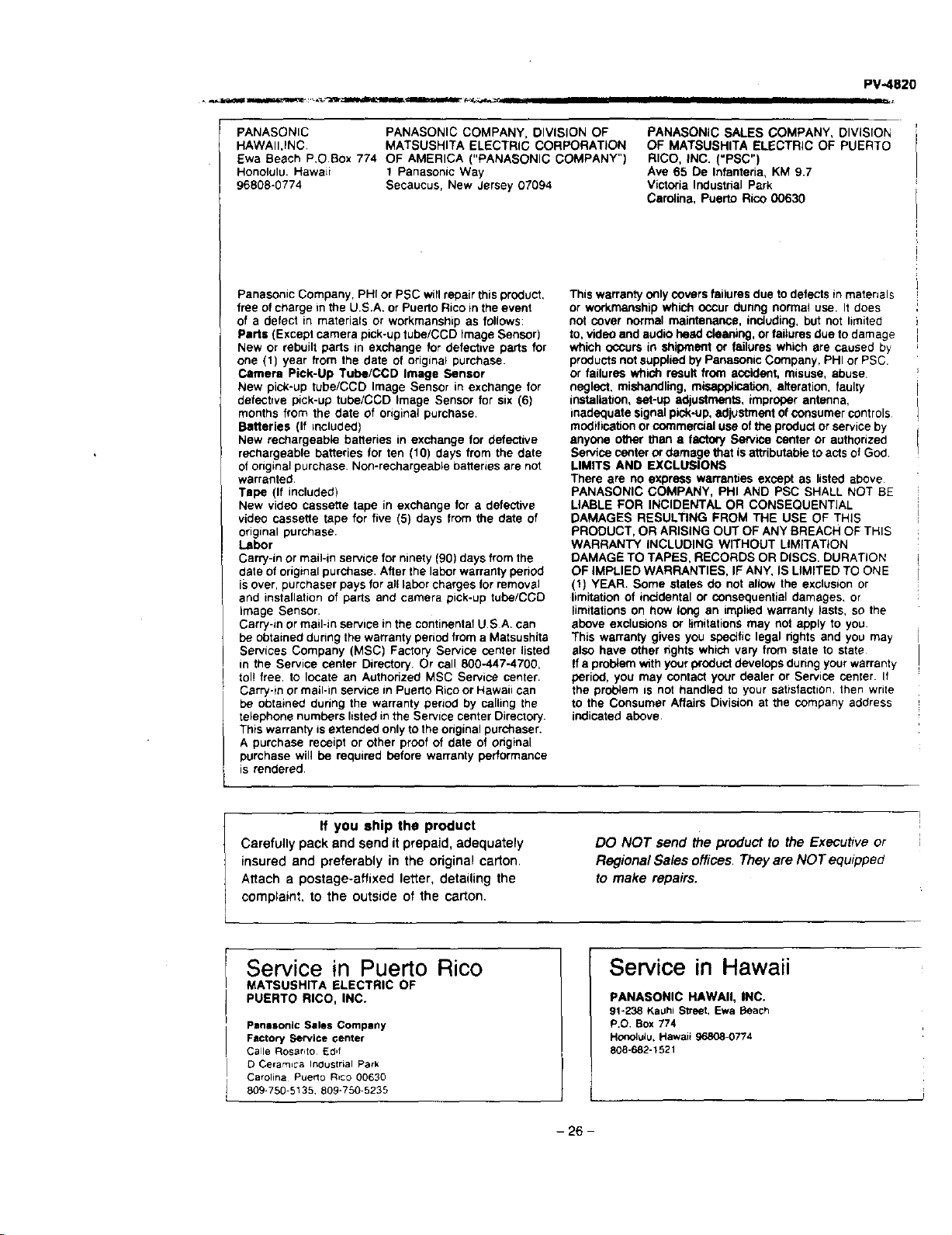
PV-4820
PANASONIC PANASONIC COMPANY, DIVISION OF
HAWAII.INC. MATSUSHITA ELECTRIC CORPORATION
Ewa Beach P.O.Box 774 OF AMERICA ("PANASONIC COMPANY")
Honolulu. Hawaii I Panasonic Way
96808-0774 Secaucus, New Jersey 07094
PANASONIC SALES COMPANY, DIVISION
OF MATSUSHITA ELECTRIC OF PUERTO
RICO, INC. ("PSC")
Ave 65 De Infanteria, KM 9.7
Victoria Industrial Park
Carolina, Puerto Rico 00630
Panasonic Company, PHI or PSC will repair this product,
free of charge in the U.S.A. or Puerto Rico in the event
of a defect in materials or workmanship as follows:
Parts (Except camera pick-up tube/CCD Image Sensor)
New or rebuilt parts in exchange for defective parts for
one (1) year from the date of original purchase.
Camera Pick-Up Tube/COD Image Sensor
New pick-up tube/COD Image Sensor in exchange for
defsottve pick-up tube/CCD image Sensor for six (6)
months from the date of original purchase.
Batteries (If included)
New rechargeab_e batteries in exchange for defective
rechargeable batteries for ten (10) days from the date
of original purchase Non-rechargeable batteries are not
warranted
Tape (If included)
New video cassette tape in exchange for a defective
video cassette tape for five (5) days from the date of
original purchase
Labor
Carry-in or mail-in service for ninety (90) days from the
date of original purchase. After the labor warranty pehod
is over, purchaser pays for al! labor charges for removal
and installation of parts and camera pick-up tUbo/CCD
Image Sensor.
Carry-in or mall-in service in the continental U.S A. can
be obtained dunng the warranty period from a Matsushita
Services Company (MSC) Factory Service center listed
in the Service center Directory. Or call 800-447-4700,
tol! free. to locate an Authorized MSC Service center.
Carry-m or mail-in service in Puerto Rico or Hawaii can
be obtained duhng the warranty period by calling the
telephone numbers listed in the Service center Directory.
This warranty isextended only to the original purchaser.
A purchase receipt or other proof of date of ohginal
purchase will be required before warranty performance
is rendered.
This warranty o_ly covers failures due to defects in matenals
or workmanship which occur dunng normal use. It does
not cover normal maintenance, including, but not limitac
to, video and audio head cleaning, Orfailures due to damage
which occurs in shipment or failures which are caused by
products not supplied by Panesonic Company, PHI or PSC.
or failures which result from accident, misuse, abuse.
neglect, mishandling, misapplication, alteration, faulty
installation, set-up adjustments, improper antenna,
inadequate signal pick-up, adjustment of consumer controls
modification or commercial usa of the product or service by
anyone other than a factory Sewme center or authorized
Service center Ordamage that isattributable to acts of God
LIMITS AND EXCLUSIONS
There are no express warranties except as listed above
PANASONIC COMPANY, PHI AND PSC SHALL NOT BE
LIABLE FOR INCIDENTAL OR CONSEQUENTIAL
DAMAGES RESULTING FROM THE USE OF THIS
PRODUCT, OR ARISING OUT OF ANY BREACH OF THIS
WARRANTY INCLUDING WITHOUT LIMITATION
DAMAGE TO TAPES, RECORDS OR DISCS. DURATION
OF IMPLIED WARRANTIES, IF ANY, IS LIMITED TO ONE
(t) YEAR. Some states do not allow the exclusion or
limitation of incidental or consequential damages, or
limitations on hOw long an implied warranty lasts, so the
above exclusions or limitations may not apply to you
This warranty gives you specific legal nghts and you may
also have other rights which vary from state to state
If a problem with your product develops dunng your warranty
period, you may contact your dealer or Service center. If
the problem is not handled to your satisfaction then write
to the Consumer Affairs Division at the company address
indicated above.
If you ship the product
Carefully pack and send itprepaid, adequately DO NOT send the product to the Executive or
insured and preferably in the original carton. Regional Sa/es offices. They are NOT equipped
Attach a postage-affixed letter, detailing the to make repairs.
complaint, to the outside of the carton.
Service in Puerto Rico
MATSUSHITA ELECTRIC OF
PUERTO RICO, INC.
Panasonlc Sales Company
Factory Service center
Calle Rosarlto Ed,f
O Cerarn=_a Industrial Psrk
Carolina Puerto Rico 00630
809-750-5135. 809-750-5235
Service in Hawaii
PANASONIC HAWAII, INC.
91-238 Kauhi Street, Ewa Beach
P.O. Box 774
HOnolulu. Hawaii 96808-0774
808-682-1521
- 26 -
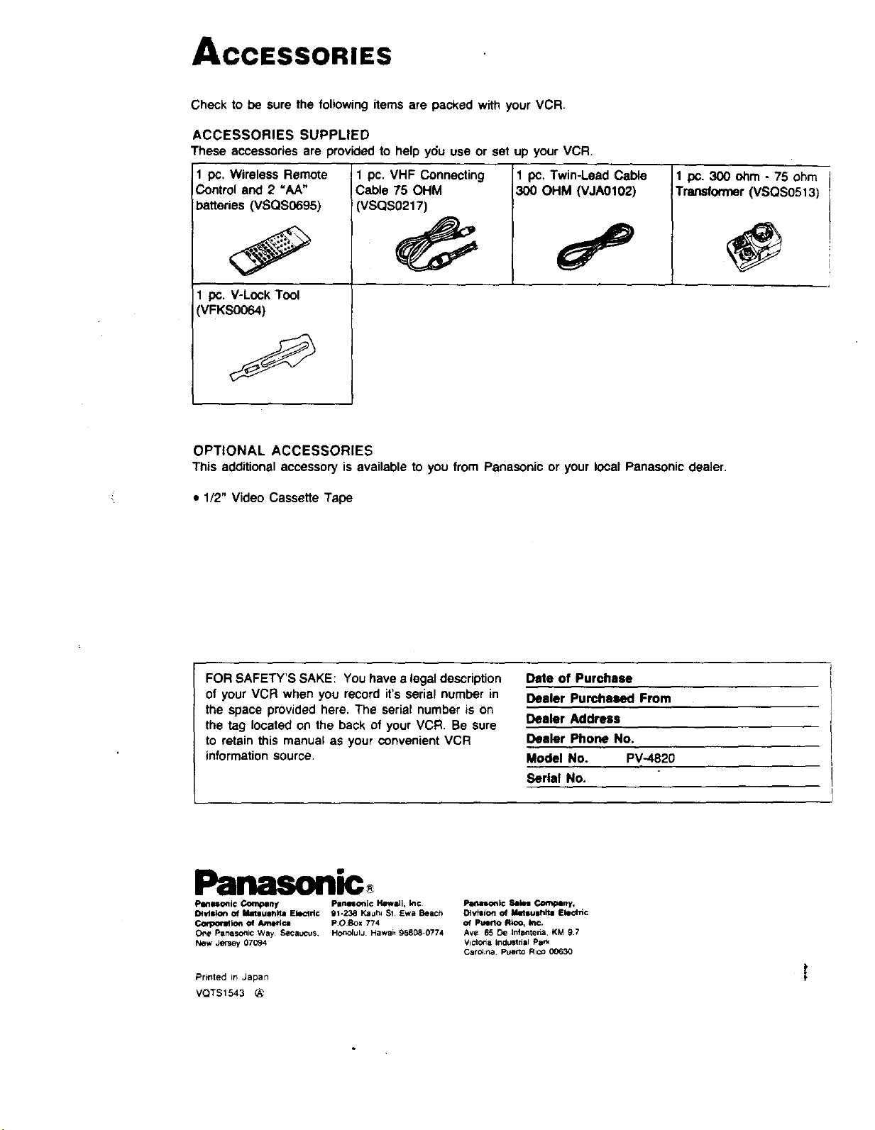
ACCESSORIES
Check to be sure the following items are packed with your VCR.
ACCESSORIES SUPPLIED
These accessories are provided to help ydu use or set up your VCR.
1 pc. Wireless Remote
Control and 2 "AA"
batteries (VSQS0695)
I pc. V-Lock Tool
VFKS0064)
1 pc. VHF Connecting
Cable 75 OHM
VSQS0217)
1 pc. Twin-LeadCable
300 OHM (VJA0102)
1 pc. 300 ohm - 75 ohm
Transformer (VSQS0513)
OPTIONAL ACCESSORIES
This additionalaccessoryis availableto you from Panasonicor your localPanasonicdealer.
• 1/2" Video Cassette Tape
FOR SAFETY'S SAKE: You have a legal description
of your VCR when you record it's serial number in
the space provided here. The serial number is on
the tag located on the back of your VCR. Be sure
to retain this manual as your convenient VCR
information source.
Date of Purchase
Dealer Purchased From
Dealer Address
Dealer Phone No.
Model No. PV-4820
Serial No.
Panasollic
PIItl_onic Corny Pllnloonic H4mw_i, I_¢
Dl.,dll_on of Matllu|h_la EkKlrl© 91-238 Kauh_ $1 Ewe Beach
Corpormion Of _'lc= POBox 7"/4
OP_ Panasonic Way Secauc_*s HonOlulu Hawaii 96808-0774
New Jersey 07094
Prirlted in Japan
VQTS1543
Petlalonl¢ _14m C_'_plny,
DIvtllon of Mnlulhltm Electric
of Ptmrto Rico, in(:.
Ave 65 De Infantena KM 97
Victo_a IndtJstnal Park
CarOlJna p_mrto RtcO 00630
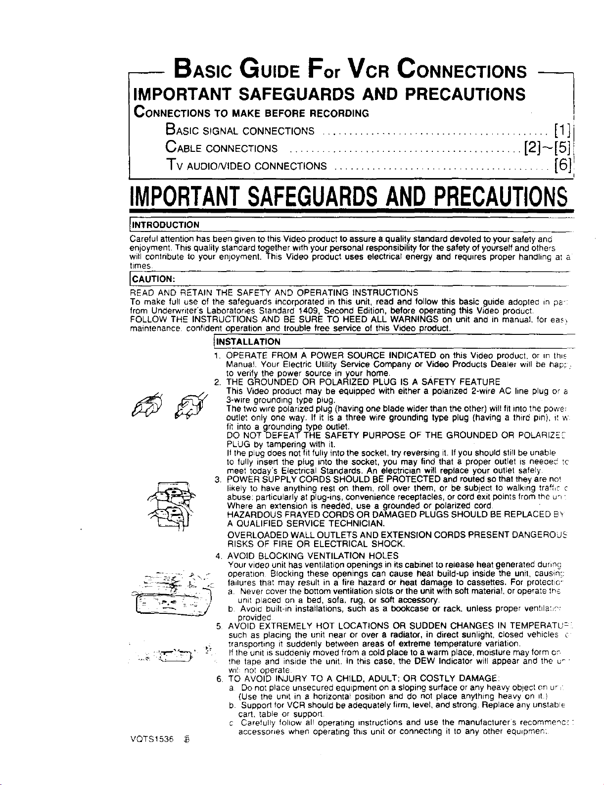
BASIC GUIDE For VCR CONNECTIONS
IMPORTANT SAFEGUARDS AND PRECAUTIONS
CONNECTIONS TO MAKE BEFORE RECORDING
BASICSIGNAL CONNECTIONS .......................................... [1]1
CABLE CONNECTIONS ........................................... [2] _'[5] I
Tv AUDIO/VIDEO CONNECTIONS ........................................ [6]
i
IMPORTANTSAFEGUARDSANDPRECAUTIONS
INTRODUCTION
Careful attention has been given to this Video product to assure a quality standard devoted to your safety and
enjoyment, This quality standard together with your personal responsibility for the safety of yourself and others
witl contribute to your enjoyment. This Video product uses electrical energy and requires proper handling a; a
times.
CAUTION:
READ AND RETAIN THE SAFETY AND OPERATING INSTRUCTIONS
To make full use of the safeguards incorporated in this unit, read and follow this basic guide adoptec in ps:
from Under'writer's Laboratories Standard 1409, Second Edition, before operating this Video product.
FOLLOW THE INSTRUCTIONS AND BE SURE TO HEED ALL WARNINGS on unit and in manual, for eas_
maintenance confident operation and trouble free service of this Video product.
INSTALLATION
1, OPERATE FROM A POWER SOURCE INDICATED on this Video product, or in thl_
Manual. Your Electric Utility Service Company or Video Products Dealer will be hap; :
to verify the power source in your home.
2. THE GROUNDED OR POLARIZED PLUG IS A SAFETY FEATURE
This Video product may be equipped with either a polarized 2-wire AC line plug or a
_ 3-wire grounding type p_ug.
The two w=repolarized plug (having one blade wider than the other) will fit into the powe
cutlet only one way. If it is a three wire grounding type plug (having a third pin), it v,
fit into a grounding type outlet.
DO NOT DEFEAT THE SAFETY PURPOSE OF THE GROUNDED OR POLARIZEF
PLUG by tampering with it.
Ifthe plug does not fit fully into the socket, try reversing it. If you should still be unab!e
to fully insert the plug into the socket, you may find that a proper outlet is needed tc
meet today's Electrical Standards. An electrician will replace your outlet safely
3. POWER SUPPLY CORDS SHOULD BE PROTECTED and routed so that they are not
_ likely to have anything rest on them, roll over them, or be subject to walking traffic c
abuse: particularly at plug-ms, convenience receptacles, or cord exit points from the ur_•
Where an extension is needed, use a grounded or polarized cord
HAZARDOUS FRAYED CORDS OR DAMAGED PLUGS SHOULD BE REPLACED B_'
A QUALIFIED SERVICE TECHNICIAN.
OVERLOADED WALL OUTLETS AND EXTENSION CORDS PRESENT DANGEROUS
RISKS OF FIRE OR ELECTRICAL SHOCK.
4. AVOID BLOCKING VENTILATION HOLES
Your video unit has ventilation openings in its cabinet to release heat generated during
_=_ =;._-. _\? operation Blocking these openings can cause heat build-up inside the unit causm_
= _'"' _ - failures that may result in a fire hazard or heat damage to cassettes. For protect_e"
, -'ft " "-_ "_,- a Never cover the bottom ventilation slots or the unitwith soft material, or operate Ins
! unit placed on a bed, sofa, rug, or soft accessory.b Avoid built-in installations, such as a bookcase or rack, unless proper venttla:_?r
provided
5 AVOID EXTREMELY HOT LOCATIONS OR SUDDEN CHANGES IN TEMPERATU:
such as placing the unit near or over a radiator, in direct sunlight, closed vehicles c
,: transporting it suddenly between areas of extreme temperature variation.
.._. : _' :" If the unit is suddenly moved from a cold place to a warm place, moisture may form or
the tape and inside the unit, tn this case, the DEW Indicator will appear and the u_ •
wl!: not operate
6 TO AVOID INJURY TO A CHILD, ADULT; OR COSTLY DAMAGE:
a Do not place unsecured equipment on a sloping surface or any heavy object on ur,"
(Use the unit in a horizontal position and do not place anything heavy on tt )
b Support for VCR should be adequately firm, level and strong. Replace any unstab!e
cart. table or support
c Carefully follow all operating instructions and use the manufacturers recommenc.: "
accessones when operating th_s unit or connecting it to any other equdpmen:
VQTS1536 ,_
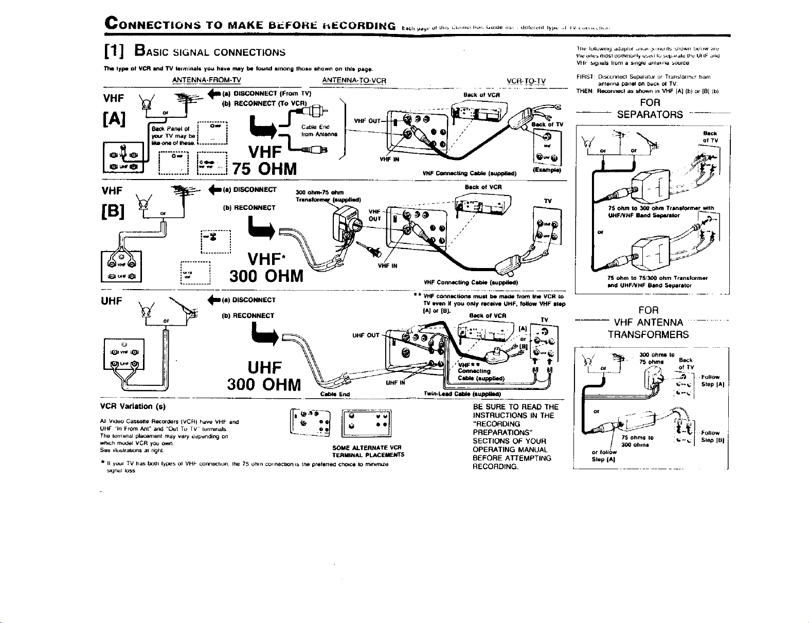
CONNECTION_ TO MAKE IBrJ.FOH_: hECOIRDING _0,,,°_.._,.,,__....................... _,,,:,_,,.,_., ,_........ ,.....
[1] BAsicS,GNALCO.NECTmONS
The type of VCR end TV termineJs yo,_ have may be Iou_l among those shown on thla page.
ANTENNA-FROM-TV ANTENNA-TO*VCR
VHF _/ _ 4_Ila) DISCONNECT (From TV)
"'- _ T- (hiRECONNECTiTO_
_la_ Par,el Of
_ Tot_MgI_Y s_. ', ......... 2 from Ante.n8
......... VN
I O_ I I 1 W I l|
I : Io.= I
Li'.Ji5.:_::.175OHM
VHF IN
VCR-T#_LV
BaCk of VCR
'/HF I_llnldlnll Clble (l_p_kKI) (|xlltl_4)
(I DISCONNECT Beck of VCR
VHF , _ 4m ) _o_Tso_
..........
VHF Connecting Clile (tal_kKI)
UHF _1--_(11) OISCONNECT * * VHF connlN:tlonl mual be made f¢om Ihe VCR to
TV evam if you only _:_ve UHF, follow VHF slop
[AJ or IaJ-
(b) RECONNECT RaCk of VCR
TV
UHF OUT
UHF
300 OHM
VCR Variation (s)
Twin-LeadCable (mupptkKI)
BE SURE TO READ THE
INSTRUCTIONS IN THE
"RECORDING
PREPARATIONS"
SECTIONS OF YOUR
OPERATING MANUAL
BEFORE ATTEMPTING
RECORDING.
All Vz0eo CasKette Recor_ts (VCR} have VHF and
UHt- .in From Ant" and "Out To TV lurmrnals
The terminal pl_cemenl may valy d_punding on
w_h mudel VCR you own
See ilio_ltahons al righl
SOME ALTERNATE VCR
TERMINAL PLACEMENTS
ii your TV has both types OI VHP (;OIInl)Cllon. Iht_ 75 Ohlll COrreCtION ¢P*tile preletfeO cllOI_ Io m_m=ze
_lgnal loss
VIIF _.lgnUl_ Irom _l _ngle dfllUll_a _OU_CU
FIR_I Dl_¢gtltl_l(;lSupalatur or Tlall_lOllfiCr ftOll;
anlel_na p3nel on bu_k ol TV
TH_N: R#r_lgl as lhowr_ in VHF [A] (b) Of [B l (b)
FOR
SEPARATORS
.T.'>
?S ohm to 300 ohm Transformer wllh
75 ohm to 75;300 ohm Ttanslormer
FOR
--- VHF ANTENNA
TRANSFORMERS
75 ohms to ,_..
300 ohme
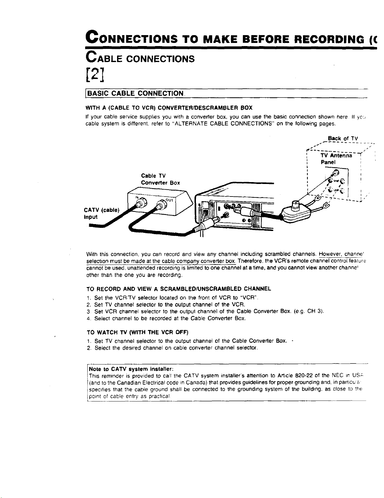
CONNECTIONS TO MAKE BEFORE RECORDING ((
I II
CABLE CONNECTIONS
[2]
[BASIC CABLE CONNECTION,
WITH A (CABLE TO VCR) CONVERTER/DESCRAMBLER BOX
If your cable service supplies you with a converter box, you can use the basic connection shown here If yd.,
cable system is different, refer to "ALTERNATE CABLE CONNECTIONS" on the following pages.
Back of TV
f,_ /"
TV Anne-n-n;--_
Panel
CATV (cable)
Input
Cable TV
Converter Box
With this connection, you can record and view any channel including scrambled channels, However, channe _
selection must be made at the cable company converter box. Therefore, the VCR's remote channel control feature
cannot be used, unattended recording is limited to one channel at a time, and you cannot view another channe'
other than the one you are recording.
TO RECORD AND VIEW A SCRAMBLED/UNSCRAMBLED CHANNEL
1. Set the VCR_rV selector located on the front of VCR to "VCR".
2. Set TV channel selector to the output channel of the VCR.
3 Set VCR channel selector to the output channel of the Ceble Converter Box. (e.g, CH 3).
4 Select channel to be recorded at the Cable Converter Box.
TO WATCH TV (WITH THE VCR OFF)
1, Set TV channel selector to the output channel of the Cable Converter Box,
2, Select the desired channel on cable converter channel selector.
Note to CATV system installeir:
This reminder is provided tO ca r the CATV system installer's atlention to Article 820-22 of the NEC in US;.
(and to the Canadian Electrical code in Canada) that provides guidelines for proper grounding and, in particu'a
specifies that the cable ground shall be connected to the grounding system of the building, as close to th_
point O cable entry as pract ca!
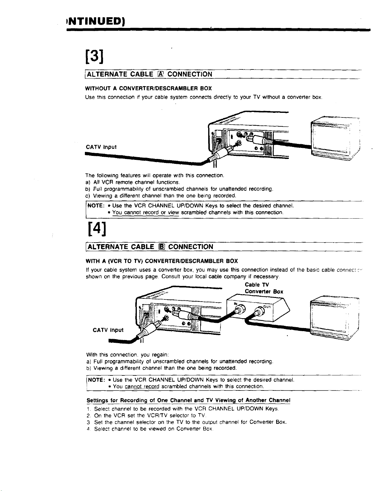
INTINUED)
[3]
IALTERNATE CABLE I_ CONNECTION
WITHOUT A CONVERTER/DESCRAMBLER BOX
Use thisconnectionifyour cablesystemconnectsdirectlyto yourTV withouta converterbox.
CATV Input
The following features will operate with this connection.
a) All VCR remote channel functions.
b) Full programmability of unscrambled channels for unattended recording.
c) Viewing a different channel than the one being recorded.
NOTE: • Use the VCR CHANNEL UP/DOWN Keys to select the desired channel
• You cannot record or view scrambled channels with this connection,
[41
[ALTERNATE CABLE [] CONNECTION
WITH A (VCR TO TV) CONVERTER!DESCRAMBLER BOX
If your cable system uses a converter box, you may use this connection instead of the basic cable connec: _,
shown on the previous page. Consult your local cable company if necessary
Cable TV
Converter Box
CATV Input
With this connection, you regain:
a) Full programmability of unscrambled channels for unattended recording.
b) Viewing a different channel than the one being recorded.
INOTE: • Use the VCR CHANNEL UP/DOWN Keys to select the desired channeJ.
• You cannot record scrambled channels with this connection.
l
Settings for Recording of One Channel and TV Viewing of Another Channel
1. Select channel to be recorded with the VCR CHANNEL UP/DOWN Keys.
2 On the VCR set the VCR,'TV selector to TV
3 Set the channel selector on the TV to the output Channel for Converter Sex.
4 Select channel to be viewed on Converter Box
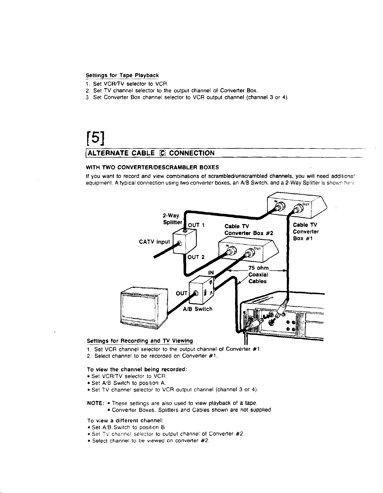
Settings for Tape Playback
1 Set VCRFFV selector to VCR
2, Set TV channel selector to the output channel of Converter Box.
3 Set Converter Box channel selector to VCR output channel (channel 3 or 4).
[5]
IALTERNATE CABLE [_ CONNECTION
WITH TWO CONVERTER/DESCRAMBLER BOXES
If you want to record and view combinations of scrambled/unscrambled channels, you will need additiona'
equipment. Atypical connection using two converter boxes, an A!B Switch, and a 2-Way Splitier is showr_ be_
2-Way
Splitter
CATV Input
Cable TV
Converter
Box #1
A/B Switch
I
Settings for Recording and TV Viewing
1. Set VCR channel selector tO the output channel of Converter #1.
2 Select channel to be recorded on Converter #1.
To view the channel being recorded:
• Set VCR,_'V selector to VCR
• Set A!B Switch to position A
• Set TV channel selector to VCR output channel (channel 3 or 4).
NOTE: • These settings are also used to view playback of a tape.
• Converter Boxes, Splitters and Cables shown are not supplied.
To view a different channel:
• Set A'B Switch to posibon B
• Se! T,J channel selector to output channel of Converter #2
• Select channel to be wewed on converter #2.
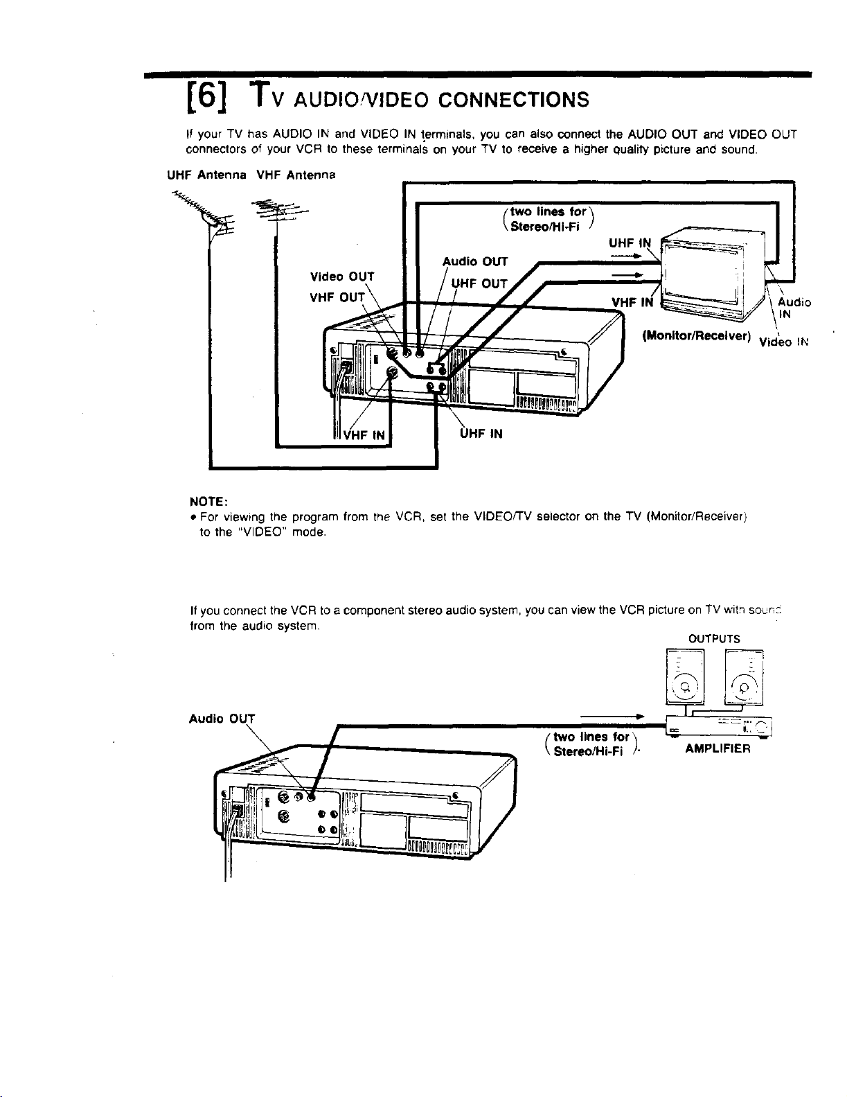
[6] Tv AUD,O ,,DEOCONNECTIONS
If your TV has AUDIO IN and VIDEO IN t,erminals, you can also oonnect the AUDIO OUT and VIDEO OUT
connectors of your VCR to these terminals on your TV to receive a higher quality picture and sound.
UHF Antenna VHF Antenna
'\
Audio
IN
(Monitor/Receiver)
Video IN
\
UHF IN
NOTE:
• For viewing the program from the VCR, set the VIDEO/TV selector on the TV (Monitor/Receiver)
to the "VIDEO" mode.
If you connect the VCR toa component stereo audio system, you can view the VCR picture on TV with sound
from the audio system,
OUTPUTS
Audio OUT
two lines for_
Stereo/Hi-Fi /" AMPLIFIER
JOUTSIDE ANTENNA, EQUIPMENT, AND POWERLINE EXPOSURE
1 INSURE SAFE ANTENNA AND CABLE CONNECTIONS
If an outside antenna or cable system is connected to the equipment, be
sure the antenna or cable system is grounded so as to provide some
protection against built up static charges and voltage surges Part 1 of the
Canadian Electrical Code, in USA Section 810 of the National Electrica!
Code. ANSI/NFPA No. 70-1984, provides information with respect to prop:,
i grounding of the mast and suppoding structure, grounding ot the lead-_r
_.,._,. wire to an antenna discharge unit, size of grounding conductors, location
..,,_.,'_'°' of antenna discharge unit, connection togrounding electrodes and
•_j,_.G, requirements for the grounding electrode. See figure 1 for items a-d below
a. Use No. 10 AWG (5 3 mm') copper, No 8 AWG (8.4 mm') aluminu r"
,,..:,._ No. 17 AWG (1.0 mm') copper-clad steel or bronze wire, or large "
_._.: .,._. ground wire.
' b. Secure antenna lead-in and ground wires to house with stand-of'
_.o,_,,_._,.,,-.oo, insulators spaced from 4 feet (1.22 m) to 6 feet (1.83 m) apart.
.-o_.,,..,_. c. Mount antenna discharge unit as close as possible to where lead-in
_o_.._ *,Ecs_c*,c, enters house.
e,o ;.. _o,
Figure 1 ......... o...... d. Use jumper wire not smaller than NO. 6 AWG (13.3 mm') copper, or
the equivalent, when a separate antenna-grounding electrode is used
See NEC Section 810-210) for installation in USA.
2. ELIMINATE ANTENNA PROXIMITY TO HIGH VOLTAGE POWER SOURCES, OR
CHANCE OF ACCIDENTAL CONTACT BY INSTALLER
An outside antenna system should be located where it will never be reached by power
lines, electric light or power circuits and where it will never contact these power sources
if it falls. Installer should use extreme care to avoid possible fatal contact by touchm?
power lines, circuits or other power sources when installing outside antenna
JusE
L-_'_._ AFTER STORING OR WHEN MOVING THE UNIT, REFER TO THE INSTALLATION
SECT,ONOETRESAFEGUARDS
_._ 1. DO NOT USE THIS VIDEO UNIT NEAR WATER around bathtubs, sinks, laundry, we_
basement, swimming pool or any water sources.
/'i 2. USE ACCESSORIES RECOMMENDED ONLY BY THE MANUFACTURER to avoid ris_,
• <
fJ'X "_'- of fire, shock or other hazards.
' 3. UNPLUG ALL EQUIPMENT EXPOSED TO RAIN, MOISTURE, OR STRONG IMPAC-
• i AND GET A QUALIFIED INSPECTION
If your unit has been exposed to rain, water, excessive moisture, or subjected to strode
impact, unplug it and have it inspected by a service technician before use,
__ _._. _ 4. UNPLUG UNUSED UNIT, AND ALL EQUIPMENT DURING A STORM
•".,.--- _- During a lightning storm, when indoors or outdoors, or before leaving unit unused to'
__ "_t_._ extended periods of time, disconnect all equipment from power source, antenna _'_::
,_.
cable system,
__-'5 5. UNPLUG ALL EQUIPMENT BEFORE CLEANING, after unithas been unplugged use a
_r,_-_'_h_r_ dry, clean, chemically untreated, cloth. Use no cleaning fluids, aerosols, or forced a,"
._ that could over-spray, or soak into the unit, and cause electrical shock. Any subslaqc:
._ .. such as wax, adhesive tape. etc. may affect the cabinet surface. Exposure to greas_
humid, or dusty areas may affect internal pans.
_.._ o 6. WHEN PLUGGED-IN: KEEP WATER AWAY; NO FINGERS INSIDE NOR ANY
OBJECTS INSIDE; AND NO MAGNETS OR ELECTRICAL INTERFERENCE NEAR£Y
.1 ._ ____;_'._ a. Never operate the unit if liquid has been spilled into it. Immediately unplug the u_
I _ have it inspected by a sen/ice technician. Fire and shock hazards can result from
electrical shorts caused by liquid contact inside.
b. Caution the children about dropping or pushing objects into the unit. Some parts
inside carry hazardous voltages and contact can cause electric shock. Objects aropp_._
in electrical equipment can cause fire hazards.
_..,., . c. Separate the unit from any interference causing appliances. Placing the unit dire::_,
above or below your TV set may cause electrical interference. Keep all magnets awa}
from electronic equipment.
ISERVICE
1. DO NOT ATTEMPT TO SERVICE THIS PRODUCT YOURSELF
If this Video product does not operate as described, when the detailed Operating Instructions are fo Io ._.
do not attempt to open or remove covers, or make any adjustments not described in the manual. Attemptin_
to service this unit yourself may expose you to dangerous voltage or other hazards. Refer all servicin£ t_
qualified service personnel.
2. CHECK ON REPLACEMENT PARTS REQUIRED, be sure the service technician has used replacement par::
specified by the manufacturer or having the same characteristics as the original part. Unauthorized substitute_
may result in fire, electric shock or other hazards,
3 HAVE TECHNICIAN PERFORM SAFETY CHECK described in the manufacturer's service literature, afler ar_.
service or repairs, to determine the Video unit's sate operating order.
Printed m Ja,q_
IB 54000001 VOTS1536
MARKEt
Thanks for t_dng lh_ _ lo _l out I1il _UlNl_O_ll_kll. Your W'llWlell wll h" tmld lot rllmlk_ elm_l_h _ anO
refx)ds -- and wi# limp ul beam" irene y_J M lie figure. I_Iy _!1 _10 Ik_o_ "_l_uI0 flollve _ _li_s anO
special offers from a number of fine m M pmduom _ld m m dlrecUy Io the _oec_c interests¸
hobbies, emd olher kdo_nabo_ indicated above. "1_ It_ U I_Ogrlm_ YOUwal be Male Io ot_a_n more knformation
abo_ ac_._oes k_ which you em V_,mlved and less /l_ II_le In _ you m rmL Pl_m dr,eck m. # _ _me
m
mason, you w_JIO pride," hoe _ parl_pate _ lY,s oppoduNly. _ ,.._: _ , ...... •
1986 Na_onal DemograpNcs& _ IncAir_ Reined
k over
CKIb,Cute BlanChe
Card, V'ma)
it €_l(s)
Printed in Japar
V_AS0169