Loading ...
Loading ...
Loading ...
APPLICATION | 49
Application Guidelines
Due to our policy of continuous product innovation, some specications may change without notication.
©
LG Electronics U.S.A., Inc., Englewood Cliffs, NJ. All rights reserved. “LG” is a registered trademark of LG Corp.
When deciding on a location to place the outdoor unit, be sure to choose an area where run-off from defrost will not accumulate and freeze on sidewalks
or driveways, which may create unsafe conditions. Properly install and insulate any drain hoses to prevent the hose from freezing, cracking, leaking,
and causing unsafe conditions from frozen condensate.
Planning for Snow and Ice, continued.
Tie-Downs and Lightning Protection
Tie-Downs
• The strength of the roof must be checked before installing the
outdoor units.
• If the installation site is prone to high winds or earthquakes, when
installing on the wall or roof, securely anchor the mounting base
using a field-provided tie-down configuration approved by a local
professional engineer.
• The overall tie-down configuration must be approved by a local
professional engineer.
Always refer to local code when using a wind restraint system.
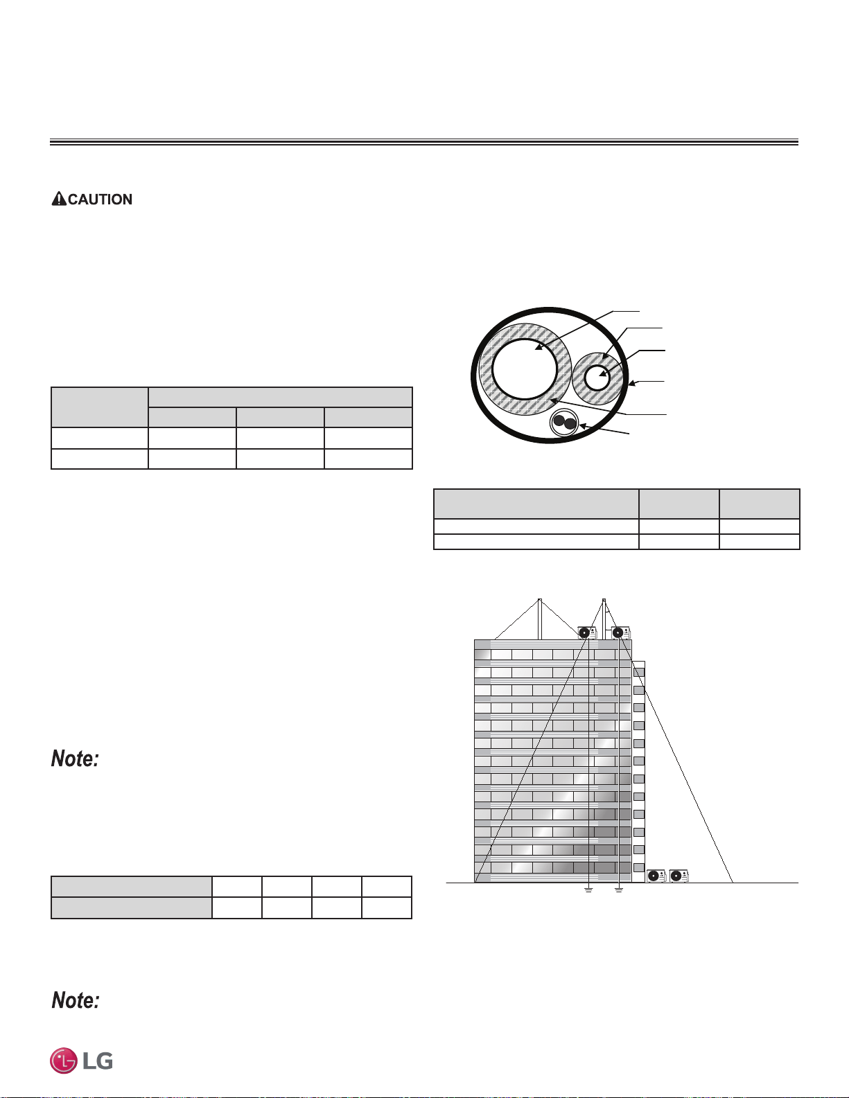
Lightning Protection
• To protect the outdoor unit from lightning, it must be placed within
the specified lightning safety zone.
• Power cable and communication cable must be installed five (5) feet away from lightning rod.
• A high-resistance ground system must be included to protect against induced lightning or indirect strike.
Building Height (feet)
66 98 148 197
Protection Angle (˚)
55 45 35 25
If the building does not include lightning protection, the outdoor unit may be damaged from a lightening strike. Inform the customer of this possibility
in advance.
Figure 24: Typical Arrangement of Refrigerant Pipe and Cable(s) in a
Utility Conduit.
PLACEMENT CONSIDERATIONS
Outdoor Unit
Ground
Safe zone
Lightning rod
Protection Angle (25˚~55˚)
5 feet
Lightning rod
Underground Refrigerant Piping
Refrigerant pipe installed underground must be routed inside a vapor
tight protective sleeve to prevent insulation deterioration and water
infiltration. Refrigerant pipe installed inside underground
casing must be continuous without any joints. Underground
refrigerant pipe must be located at a level below the frost line.
Figure 25: Lightning Protection Diagram.
Table 25: Utility Conduit Sizes (Inches).
1
OD pipe diameter in inches; Values in parenthesis () indicate OD of pipe with insulation jacket.
2
Diameter of pipe with insulation. Thickness of pipe insulation is typical. Actual required thickness may
vary based on surrounding ambient conditions and must be calculated and specified by the design
engineer.
3
Insulation thickness (value in parenthesis) = 3/8 inch.
4
Insulation thickness (value in parenthesis) = 3/4 inch.
Liquid Pipe
1
Vapor Pipe
1
3/8 (1-1/8
2,3
) 1/2 (2.0
2,4
) 5/8 (2-1/8
2,4
)
1/4 (1.0)
4
4 4 4
3/8 (1-1/8)
4
4 4 4
Table 26: Outdoor Unit Refrigerant Pipe Connections (All Brazed Type).
Vapor Line
Liquid Line
Min. 18 Gauge
Cable
Power/Communication
Pi
p
e Sleeve
Insulation Material
Insulation
Material
Model
Liquid Conn.
(inches)
Vapor Conn.
(inches)
LSU090HSV5, LSU120HSV5 1/4 3/8
LSU180HSV5 3/8 5/8
Table 27: Safety Zone Specifications.
Loading ...
Loading ...
Loading ...