Loading ...
Loading ...
Loading ...
_._ PIVOT ADJUSTMENTS
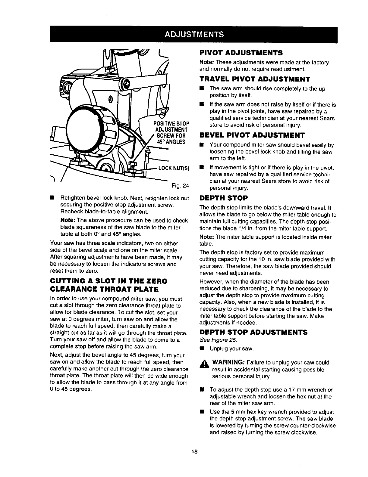
POSITIVESTOP
ADJUSTMENT
SCREWFOR
45°ANGLES
Fig. 24
• Retighten bevel lock knob. Next, retighten locknut
securing the positive stop adjustment screw.
Recheck blade-to-table alignment.
Note: The above procedure can be used to check
blade squareness of the saw blade to the miter
table at both 0° and 45° angles.
Your saw has three scale indicators, two on either
side of the bevel scale and one on the miter scale.
After squaring adjustments have been made, it may
be necessary to loosenthe indicators screws and
reset them to zero.
CUTTING A SLOT IN THE ZERO
CLEARANCE THROAT PLATE
In order to use your compound miter saw, you must
cut a slot through the zero clearance throat plate to
allow for blade clearance. To cut the slot, set your
saw at 0 degrees miter, turn saw on and allow the
blade to reach full speed, then carefully make a
straight cut as far as it will go through the throat plate.
Turn your saw off and allow the blade to come to a
complete stop before raising the saw arm.
Next, adjust the bevel angle to 45 degrees, turn your
saw on and allow the blade to reach full speed, then
carefully make another cut through the zero clearance
throat plate. The throat plate willthen be wide enough
to allow the blade to pass through it at any angle from
O to 45 degrees.
Note: These adjustments were made at the factory
and normally do not require readjustment.
TRAVEL PIVOT ADJUSTMENT
• The saw arm should rise completely to the up
position by itself.
If the saw arm does not raise by itself or if there is
play in the pivot joints, have saw repaired by a
qualified service technician at your nearest Sears
store to avoid risk of personal injury.
BEVEL PIVOT ADJUSTMENT
• Your compound miter saw should bevel easily by
loosening the bevel lock knob and tilting the saw
arm to the left.
• If movement is tight or if there is play in the pivot,
have saw repaired by a qualified service techni-
cian at your nearest Sears store to avoid risk of
personal injury.
DEPTH STOP
The depth stop limits the blade's downward travel. It
allows the blade to go below the miter table enough to
maintain full cutting capacities. The depth stop posi-
tions the blade 1/4 in. from the miter table support.
Note: The miter table support is located inside miter
table.
The depth stop is factory set to provide maximum
cutting capacity for the 10 in. saw blade provided with
your saw. Therefore, the saw blade provided should
never need adjustments.
However, when the diameter of the blade has been
reduced due to sharpening, it may be necessary to
adjust the depth stop to prov!de maximum cutting
capacity. Also, when a new blade is installed, it is
necessary to check the clearance of the blade to the
miter table support before starting the saw. Make
adjustments if needed.
DEPTH STOP ADJUSTMENTS
See Figure 25.
• Unplug your saw.
,_ WARNING: Failure to unplug your saw could
result in accidental starting causing possible
serious personal injury.
• To adjust the depth stop use a 17 mm wrench or
adjustable wrench and loosen the hex nut at the
rear of the miter saw arm.
Use the 5 mm hex key wrench provided to adjust
the depth stop adjustment screw. The saw blade
is lowered by turning the screw counter-clockwise
and raised by turning the screw clockwise.
18
Loading ...
Loading ...
Loading ...