Loading ...
Loading ...
Loading ...
_k WARNING: To prevent accidental startingthat
could cause possible serious personalinjury,
assemble all parts to your saw before connecting
it to power supply. Saw should never be
connected to power supply when you are
assembling parts, making adjustments, installing
or removing blades, or when not in use.
As mentioned previously your saw has been factory
assembled and adjusted. The miter lock handle, dust
guide, and blade are the only parts that have to be
installed.
MITER LOCK HANDLE
See Figure 8.
To install the miter lock handle, place the threaded
stud on the end of the miter lock handle into the
threaded hole in the control arm. Turn clockwise to
tighten.
LOOSEN
TIGHTEN
CONTROL
ARM
MITER
MITER TABLE
LOCKHANDLE
Fig. 8
DUST GUIDE
See Figure 9.
To installthe dust guide, place the end marked
INSERT over the exhaust port in the upper blade
guard. Turn the guide so that the open end is facing
down or toward the rear of the saw.
EXHAUST
PORT
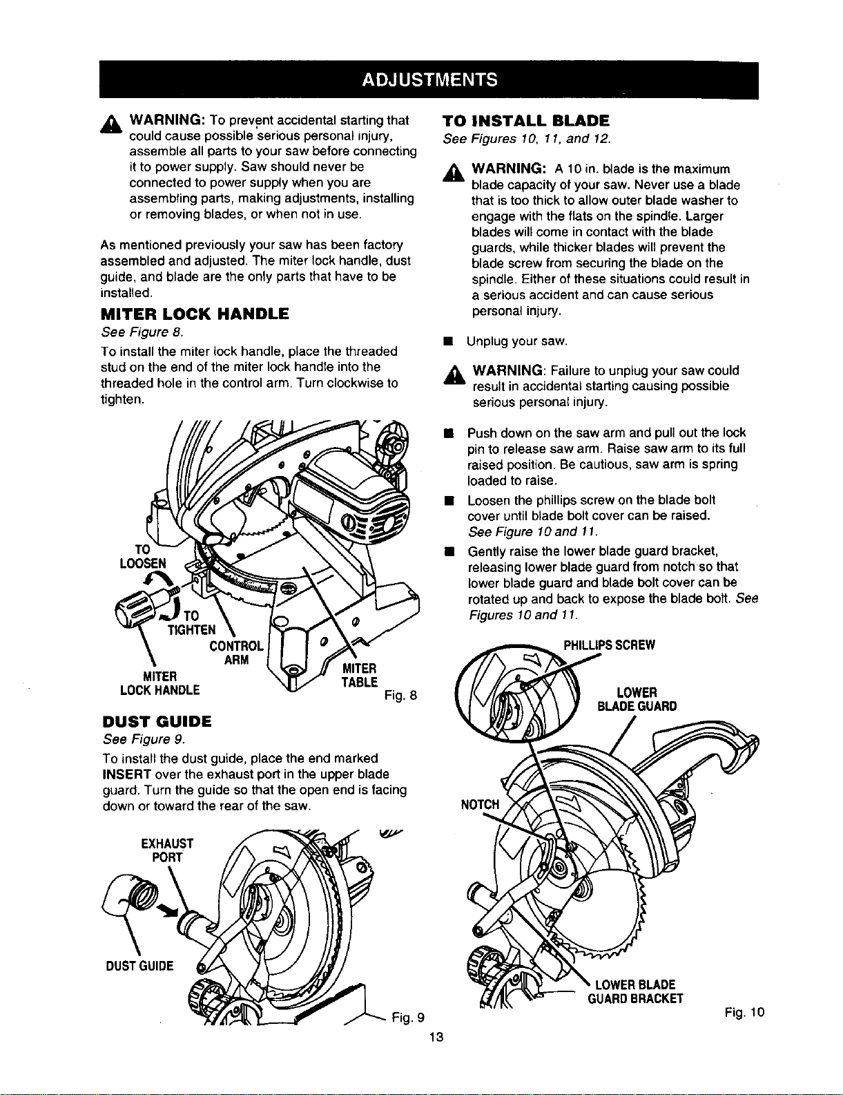
TOINSTALL BLADE
See Figures 10, 11, and 12.
A
WARNING: A 10 in. blade isthe maximum
bladecapacity of yoursaw. Never use a blade
that istoo thick to allow outerblade washer to
engage withthe flats on the spindle.Larger
bladeswillcome in contactwith the blade
guards, whilethickerblades will preventthe
blade screwfrom securingthe btade on the
spindle. Eitherofthese situationscould resultin
a seriousaccidentand can cause serious
personalinjury.
• Unplug your saw.
_ WARNING: Failure to unplug your saw could
result in accidental starting causing possible
serious personal injury.
Push down on the saw arm and pullout the lock
pin to release saw arm. Raise saw arm to its full
raised position. Be cautious, saw arm is spring
loaded to raise.
• Loosen the phillips screw on the blade bolt
cover until blade bolt cover can be raised.
See Figure lO and 11.
• Gently raise the lower blade guard bracket,
releasing lower blade guard from notch so that
lower blade guard and blade bolt cover can be
rotated up and back to expose the blade bolt. See
Figures 10 and 11.
PHILLIPSSCREW
LOWER
BLADEGUARD
DUSTGUIDE
LOWERBLADE
GUARD BRACKET
Fig. 10
Fig. 9
13
Loading ...
Loading ...
Loading ...