Loading ...
Loading ...
Loading ...
APPLICATION GUIDELINES | 59
Application Guidelines
Due to our policy of continuous product innovation, some specications may change without notication.
© LG Electronics U.S.A., Inc., Englewood Cliffs, NJ. All rights reserved. “LG ” is a registered trademark of LG Corp.
Outdoor Unit Clearances
PLACEMENT CONSIDERATIONS
Minimum Clearance Requirements for Single Zone Art Cool Premier Systems
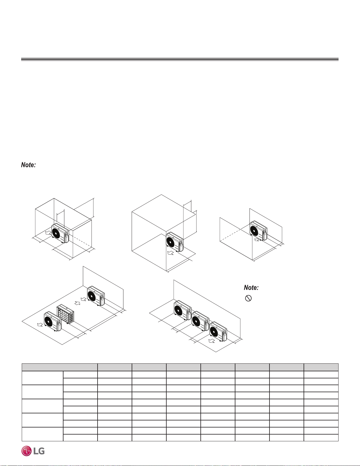
Proper clearance for the outdoor unit coil is critical for proper unit operation. When installing the outdoor unit, consider service, inlet and
outlet and minimum allowable space requirements as illustrated in the diagrams below.
Specific clearance requirements in the diagram below are for the Single Zone Wall Mounted Art Cool Premier systems. Figure 13 shows the
overall minimum clearances that must be observed for safe operation and adequate airflow around the outdoor unit.
When placing the outdoor unit under an overhang, awning, sunroof or other “roof-like structure”, observe the clearance requirements (as
shown in Cases 1 and 2 in Figure 13) for height in relation to the unit. This clearance ensures that heat radiation from the condenser is not
restricted around the unit.
Adhere to all clearance requirements if installing the unit on a roof. Be sure to level the unit and ensure that the unit is adequately anchored.
Consult local codes for rooftop mounting requirements.
In order to have successful service access to the outdoor unit, see Figure 13 for minimum spacing. When installing multiple outdoor units,
see Cases 4 and 5 in Figure 13 for correct spacing requirements.
Figure 19: Outdoor Unit Service Access and Allowable Clearances Diagram.
A
B
D
G
C
G
C
D
E
D
D
B
B
F
1/16 inch
20 inches or less
Case 1
Case 4
Case 2 Case 3
Case 5
20 inches or less
Unit: Inch A B C D E F G
Case 1
Standard 12 24 - 12 - - -
Minimum 4 10 - 4 - - 40
Case 2
Standard - - 20 - - - -
Minimum - - 14 - - - 40
Case 3
Standard - - 20 12 - - -
Minimum - - 14 4 - - -
Case 4
Standard - - - 12 24 - -
Minimum - - - 4 8 79 -
Case 5
Standard - 24 - 12 - - -
Minimum - 10 - 4 - - -
Table 30: Outdoor Unit Service Access and Allowable Clearances Diagram Legend.
Do not place the unit where animals
and/or plants will be in the path of the warm
air, or where the warm air and/or noise will
disturb neighbors.
If the outdoor unit is installed between standard and minimum clearances, capacity decreases approximately 10%.
Loading ...
Loading ...
Loading ...