Loading ...
Loading ...
Loading ...
33
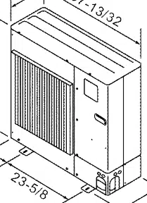
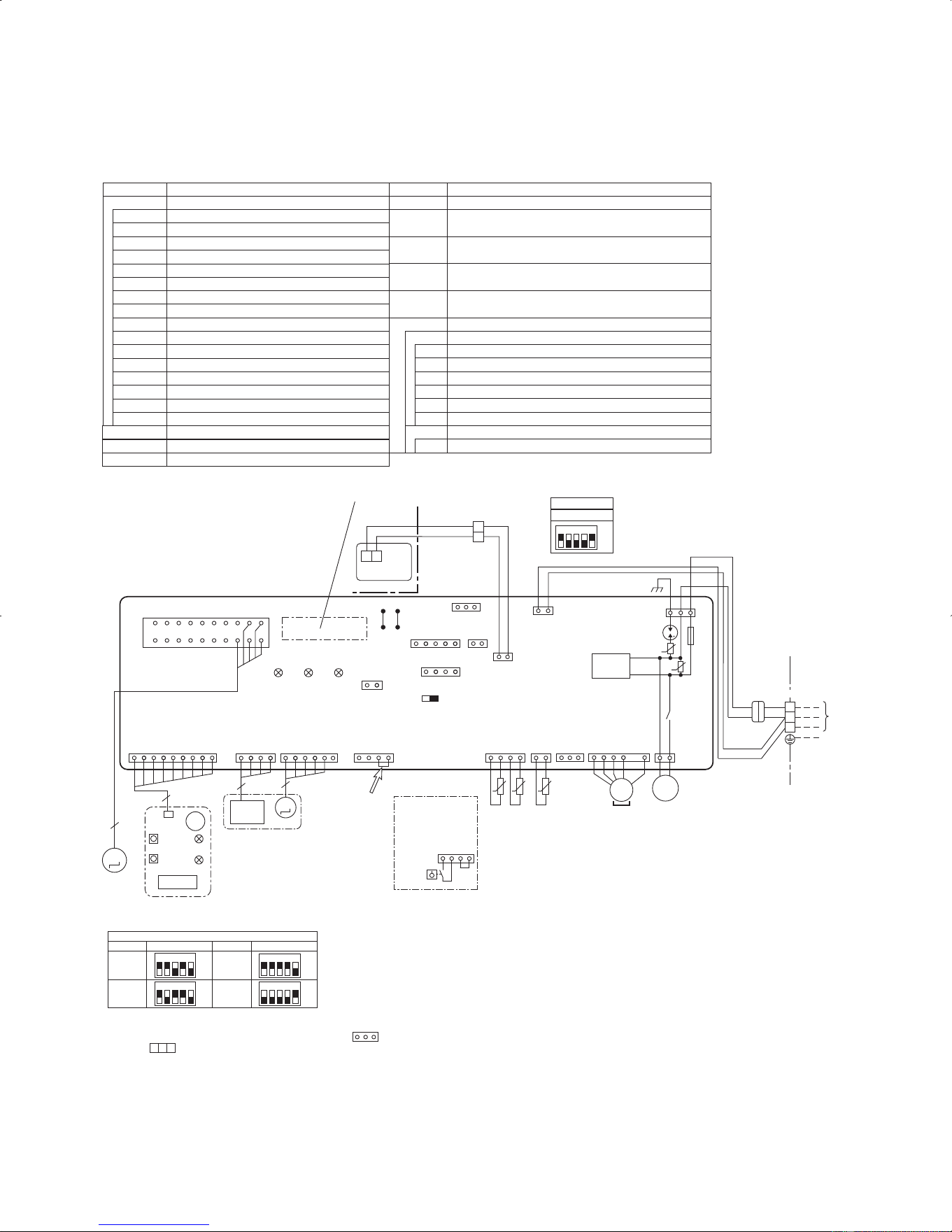
PCA-A24KA PCA-A30KA PCA-A36KA PCA-A42KA
SYMBOL SYMBOLNAME NAME
I.B
R.B
INDOOR CONTROLLER BOARD
FUSE (T6.3AL250V)
VARISTOR
SURGE ABSORBER
CONNECTOR (LOSSNAY)
CONNECTOR (REMOTE SWITCH)
CONNECTOR (HA TERMINAL-A)
CONNECTOR (CENTRALLY CONTROL)
POWER SUPPLY (I.B)
POWER SUPPLY (R.B)
TRANSMISSION (INDOOR-OUTDOOR)
RELAY (DRAIN LIFT UP MECHANISM)
WIRED REMOTE CONTROLLER BOARD
SWITCH (MODEL SELECTION) wSee table 1
SWITCH (CAPACITY CODE) wSee table 2
CONNECTOR (EMERGENCY OPERATION)
FAN MOTOR
VANE MOTOR
DRAIN LIFT UP MECHANISM
DRAIN FLOAT SWITCH
TERMINAL BLOCK (
INDOOR/OUTDOOR CONNECTING LINE
)
TERMINAL BLOCK (REMOTE CONTROLLER
TRANSMISSION LINE)
ROOM TEMP. THERMISTOR
(32ºF / 15kΩ, 77ºF/ 5. 4kΩ DETECT)
PIPE TEMP. THERMISTOR/LIQUID
(32ºF / 15kΩ, 77ºF/ 5. 4kΩ DETECT)
COND. / EVA. TEMP. THERMISTOR
(32ºF / 15kΩ, 77ºF/ 5. 4kΩ DETECT)
MF
FUSE
MV
ZNR01,02
DSA
DP
CN2L
CONNECTOR (BACK-UP HEATING)
CN24
CONNECTOR (LLC)
CN30
FS
CN32
CN41
CN51
TB4
LED1
TB5,TB6
LED2
TH1
LED3
X1
TH2
SW1
TH5
SW2
SWE
[LEGEND]
1.SymboIs used in wiring diagram above are, : Connector,
: Terminal block.
2.
Indoor and outdoor connecting wires have poIarities, make sure
to match terminal numbers (S1, S2, S3) for correct wirings.
3.Since the outdoor side electric wiring may change, be sure to
check the outdoor unit electric wiring for servicing.
w
1: Use copper supply wire.
[Self-diagnosis]
1.For details on how to operate self-diagnosis with the wireless
remote control,refer to the technical manuals etc.
2.For the wired remote control:When you quickly press twice the
CHECK switch on the remote control, the unit begins self-
diagnosis, and Check Codes generated in the past appear on
the display.
For Check Codes and Symptoms refer to the table below.
W.B
RU
BZ
LED1
LED2
SW1
SW2
OPTIONAL PARTS
PCB FOR WIRELESS REMOTE CONTROLLER
RECEIVING UNIT
BUZZER
LED (OPERATION INDICATION : GREEN)
LED (PREPARATION FOR HEATING : ORANGE)
EMERGENCY OPERATION (HEAT / DOWN)
EMERGENCY OPERATION (COOL / UP)
Notes:
FLOAT SW
CN4F
(WHT)
When attaching
drain lift up
mechanism
(optional parts),
remove the jumper
connector CN4F
and fit the drain
float switch (FS).
When attaching
drain lift up
mechanism
(optional parts)
FS
14
141 6
I-SEE
SENSOR
I-SEE
SENSOR MOTOR
CN6Y
(RED)
I-SEE
SENSOR
CN4Y
(WHT)
I-SEE SENSOR
(OPTIONAL PARTS)
4
5
MT
M
INDOOR/OUTDOOR
COMMUNICATION
CN3C
(BLU)
<Table 2>SW2(CAPACITY CODE)
Service Service
MODELS
SW2
PCA-A36KA
MODELS
ON
OFF
12345
PCA-A24KA
ON
OFF
12345
PCA-A42KA
ON
OFF
12345
PCA-A30KA
ON
OFF
12345
19
1
1
3
4
51
41
1
2
3
4
5
6
7
8
9
10
11
12
13
14
15
16
17
18
19
20
CN2L
(RED)
ON OFF
SWE
J42J41
SW2SW1
LED3 LED2 LED1
LED2
LED1
RU
SW2
SW1
CNB
9
5
t° t° t°
TH2 TH5 TH1
MV
BZ
M
W.B
TB6
R.B
I.B
14
21
21
12
21
1
2
1
2
Refer to tables 1 and 2
TRANSMISSION
WIRES
DC12V
TB4
YLW
ORN
ORN
BRN
YLW
ORN
TO OUTDOOR
UNIT
135
3
3
1
X1
M
1~
DP
D.U.M
CNP
(BLU)
ZNR02
ZNR01
FUSE
DSA
OUTDOOR
CN01
(BLK)
DC294~325V
RECTIFICATION
U
U
S1
S2
S3
741
3~
MF
MS
(OPTIONAL PARTS)
(OPTIONAL PARTS)
1
1
3
REMOCON
CN22
(BLU)
WIRELESS
CN90
(WHT)
VANE
CNV
(WHT)
Pair No.
FAN
CNMF
(WHT
)
INTAKE
CN20
(RED)
FLOAT SW
CN4F
(WHT)
LIQUID/PIPE
CN44
(WHT)
TB5
CN32
(WHT)
CN51(WHT)
CN41(WHT)
<Table 1>SW1(MODEL SELECTION)
SW1
ON
OFF
12345
w
Be sure to turn off the source power
and then disconnect fan motor connector.
(Failure to do so will cause trouble in Fan motor)
Service
CN24
(YLW)
CN30
(GRN)
w
1
DOCS1415revA.indd33DOCS1415revA.indd33 10.8.254:09:25PM10.8.254:09:25PM
Downloaded from www.ManualsFile.com manuals search engine
Loading ...
Loading ...
Loading ...