Loading ...
Loading ...
Loading ...
19
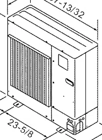
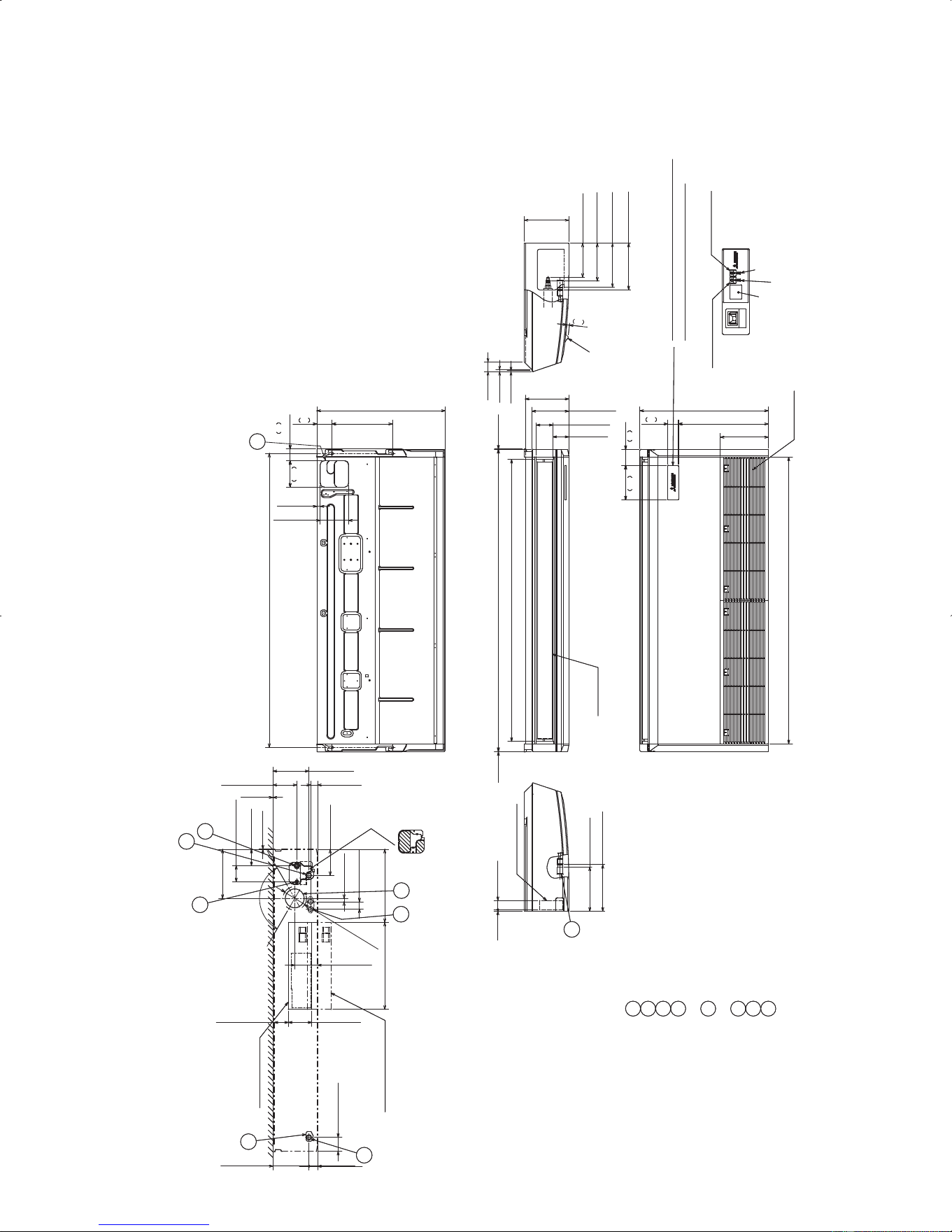
PCA-A36KA PCA-A42KA Unit: inch (mm)
When drain socket
is installed
9-3/16(233)
When drain socket
is installed
Drainage
9-11/16(246)
14
NOTES.
1.Use M10 or W3/8 screw for anchor bolt.
2.Please be sure when installing the drain lift up
mechanism (option parts),refrigerant pipe will be only upward.
6
80
26-3/4(680)
12-5/8(320)
61-5/16(1557) (Suspension bolt pitch)
11/16(18)
140
62
5-7/8(150)
2-7/165-1/2
3-1/8
Air outlet
58-3/4(1493)
1/16(2) 63(1600)
9-1/16(230)
7-11/16(195)
3-7/16(88)
3-5/16(84)
[FRONT VIEW]
5
1
1-7/8(48)5/16(8)
9-3/16(233)
1-13/16(46)
18-1/8(461)
4-7/8(124)
3(76)
7-1/2(190)
Φ
4-15/16(Φ125)
4-3/4(121)
11/16(18)
3
Electrical box
Ceiling
8
In case of the rear pipe arrangement, make sure to
remove the shaded portions from the independent piece.
Then put the independent piece back in initial
position.(The heat exchanger might be clogged because of dust)
4-15/16(126)
5-7/16(138)
1-7/16(37)
7-1/2(190)
1/16(1)
10-1/4(260)
1/16(2)
When electrical box
is pulled down
2-15/16(75)
2
1-1/2(38)
7
4
3-3/8(85)
3-3/8(86)
15-1/4(387)
2
Electrical box
Air intake
59-3/4(1518)
26-3/4(680)
18-3/4(476)
57
182
85
7-3/16 3-3/8
2-1/4
In case of wireless remote controller
and i-see sensor(Optional Parts)
Emergency operation
switch <Heating>
Operation lamp
Receiver
Emergency operation
switch <Cooling>
DEFROST/STAND BY lamp
9-5/16(236)
liquid Φ3/8(Φ9.52)
gas Φ5/8(Φ15.88)
Drainage
7-7/8(200)
9-11/16(246)
2(51)
3/8(10)
3/16(5)
9/16
In case of wireless
remote controller
and i-see sensor
(Optional Parts)
1/16(2)
1
120°
2-15/16(75)
10(254)
7-1/16(180)
Knockout hole for upper drain pipe arrangement
Knockout hole for fresh air intake Φ3-15/16(Φ100)
Knockout hole for wiring arrangement Φ7/8(Φ22)
Accessory...Drain socket (1(26mm)I.D.)
Drainage pipe connection(1(26mm)I.D.)
Drainage pipe connection(for the left arrangement)
Knockout hole for left drain-piping arrangement
Refrigerant-pipe connection
(gas pipe side/flared connection)
Refrigerant-pipe connection
(liquid pipe side/flared connection)
8
7
6
5
4
3
2
11
DOCS1415revA.indd19DOCS1415revA.indd19 10.8.254:09:21PM10.8.254:09:21PM
Downloaded from www.ManualsFile.com manuals search engine
Loading ...
Loading ...
Loading ...