perator s
P R 0 F E S S I 0 N A
LAWN TRACTOR
24 HP, 42" Tractor
Electric Start
PYT9000
Model No. 247.28980
• Espaffol, p. 62
This product has a low emission engine which operates differently
from previously built engines. Before you start the engine, read and
understand this Operator's Manual.
iMPORTANT:
Read and follow all Safety
Rules and instructions before
operating this equipment.
For answers to your questions about
this product, Call:
1=800=659=5917
Craftsman Tractor Help Line
5am = 5 pro, Mort =Sat
Sears Brands Management Corp., Hoffman Estates, IL 60179 U.S.A.
Visit our website: www.craftsman.com FormN0.769-05593
(January27,2010)
Warranty Statement .......................................................... 2
Safety instructions ............................................................ 3
Safety Labels .................................................................... 9
Assembly ......................................................................... 10
Know your Lawn Mower .................................................. 13
Operation ........................................................................ 16
CRAFTSMAN PROFESSIONAL FULL WARRANTY
Whenoperatedand maintainedaccordingto allsuppliedinstructions,ifany non-expendablepartof thisridingequipmentfailsdueto a defectin
materialor workmanshipwithintwo yearsfromthedate orpurchase,call 1-800-659-5917to arrangefor free in-homerepair.
Theframeandfrontaxle will be repairedfreeof chargefor fiveyearsfromthe dateof purchaseif defectivein materialor workmanship.
Allof the abovewarrantycoverageappliesfor onlyone yearfromthedateof purchaseif this ridingequipmentis everusedfor commercialor
rentalpurposes.
in allcases,if repairprovesimpossible,the ridingequipmentwill be replacedfree of chargewiththe sameor an equivalentmodel.
The batterywill be replacedfree of chargefor 90 daysfromthe dateof purchaseif defectivein materialorworkmanship(ourtestingprovesthat it
will notholda charge).
ThiswarrantycoversONLYdefectsin materialandworkmanship.Searswill NOT payfor:
• Expendableitemsthatbecomewornduringnormaluse,includingbutnot limitedto blades,spark plugs,air cleaners,belts,andoil filters.
• Standardmaintenanceservicing,oilchanges,or tune-ups.
Tire replacementor repaircausedby puncturesfromoutsideobjects,suchas nails,thorns,stumps,or glass.
Tireor wheelreplacementor repairresultingfromnormalwear,accident,orimproperoperationor maintenance.
Repairsnecessarybecauseof operatorabuse, includingbutnot limitedto damagecausedby towingobjectsbeyondthe capabilityof the
ridingequipment,impactingobjectsthat bendtheframeor crankshaft,or over-speedingthe engine.
• Repairsnecessarybecauseof operatornegligence,includingbut not limitedto, electricalandmechanicaldamagecausedby improper
storage,failureto usethe propergradeand amountof engineoil, failureto keepthe deckclearof flammabledebris,orfailureto maintainthe
ridingequipmentaccordingto the instructionscontainedin theoperator'smanual.
• Engine(fuelsystem)cleaningor repairscausedbyfuel determinedto becontaminatedoroxidized(stale).in general,fuel shouldbeused
within30 daysof itspurchasedate.
Normaldeteriorationandwearof the exteriorfinishes,or productlabel replacement.
Thiswarrantyappliesonly whilethisproductis withinthe UnitedStates.
Thiswarrantygivesyou specificlegalrights,andyou mayalso haveotherrightswhich vary fromstateto state.
Sears, Roebuck and Co., Hoffman Estates, IL 60179
GrossHP: 24
EngineOil: SAE30
Fuel: UnleadedGasoline
SparkPlug: Champion®RC12YC
Engine: Briggs& StrattonProfessionalSeries
Model Number
Serial Number
Dateof Purchase
Recordthe modelnumber,serialnumber,
anddateof purchaseabove.
© SearsBrands,LLC 2
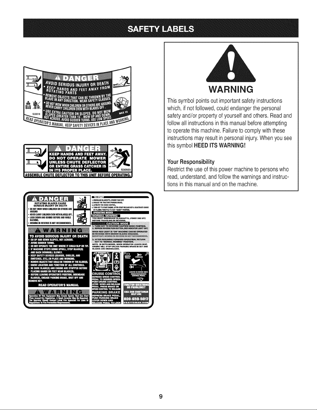
Thissymbolpointsout importantsafetyinstructionswhich,if not
followed,couldendangerthepersonalsafetyand/orpropertyof
yourselfandothers. Readandfollowall instructionsin thismanual
beforeattemptingto operatethismachine.Failureto complywith
theseinstructionsmayresultin personalinjury.Whenyou seethis
symbol,HEEDITSWARNING!
CALIFORNIA PROPOSITION 65
EngineExhaust,someof itsconstituents,andcertainvehicle
componentscontainoremitchemicalsknownto Stateof California
to causecancerand birthdefects orother reproductiveharm.
Batteryposts,terminals,and relatedaccessoriescontainleadand
leadcompounds,chemicalsknownto the Stateof Californiato
causecancerandreproductiveharm.Washhandsafter handling.
Thismachinewasbuiltto be operatedaccordingto the safeopera-
tion practicesinthis manual.As withanytypeof powerequipment,
carelessnessorerroron the partof the operatorcan resultin serious
injury.Thismachineis capableof amputatingfingers,hands,toes
andfeetandthrowingdebris.Failureto observethe followingsafety
instructionscouldresultin seriousinjuryor death.
Your Responsibility--Restrict the useof this powermachineto
personswho read,understandandfollowthewarningsand instruc-
tionsin thismanualandon the machine.
SAVE THESE INSTRUCTIONS!
GENERAL OPERATION
• Read,understand,andfollowall instructionson the machineand
in themanual(s)beforeattemptingto assembleandoperate.
Keepthis manualina safe placefor futureand regularreference
andfor orderingreplacementparts.
• Befamiliarwithall controlsandtheir properoperation.Knowhow
to stopthe machineanddisengagethemquickly.
• Neverallowchildrenunder14yearsoldto operatethis machine.
Children14yearsoldandover shouldreadandunderstandthe
operationinstructionsand safetyrulesinthismanualandshould
betrainedandsupervisedbya parent.
• Neverallowadultsto operatethis machinewithoutproper
instruction.
• Tohelpavoidbladecontactor a thrownobjectinjury,keep
bystanders,helpers,childrenandpets at least75feet fromthe
machinewhile it is in operation.Stopmachineif anyoneenters
the area.
• Thoroughlyinspectthe areawherethe equipmentis to be used.
Removeallstones,sticks,wire,bones,toys,andotherforeign
objectswhichcouldbe pickedup andthrownby the blade(s).
Thrownobjectscan causeseriouspersonalinjury.
• Planyour mowingpatternto avoiddischargeof materialtoward
roads,sidewalks,bystandersandthe like.Also, avoiddischarg-
ingmaterialagainstawall or obstructionwhichmaycause
dischargedmaterialto ricochetbacktowardthe operator.
• Alwayswear safetyglassesor safetygogglesduringoperation
andwhile performingan adjustmentor repairto protectyoureyes.
Thrownobjectswhichricochetcancauseseriousinjuryto the
eyes.
• Wearsturdy,rough-soledworkshoesandclose-fittingslacksand
shirts.Loosefittingclothesandjewelrycanbe caughtin movable
parts.Neveroperatethismachineinbare feet orsandals.
• Beawareof the mowerandattachmentdischargedirectionand
do not pointit at anyone.Donot operatethe mowerwithoutthe
dischargecoveror entiregrass catcherin its properplace.
Donot put handsor feetnearrotatingpartsor underthe cutting
deck. Contactwith the blade(s)can amputatehandsandfeet.
A missingor damageddischargecovercan causeblade contact
or thrownobjectinjuries.
• Stoptheblade(s)whencrossinggraveldrives,walks,or roads
andwhile notcuttinggrass.
• Watchfor trafficwhenoperatingnearorcrossingroadways.This
machineis not intendedfor useonany public roadway.
• Donot operatethe machinewhile underthe influenceof alcohol
or drugs.
• Mowonly indaylightor good artificiallight.
Nevercarrypassengers.
• Disengageblade(s)beforeshiftinginto reverse.Backup slowly.
Alwayslookdownandbehindbeforeandwhile backingto avoida
back-overaccident.
3
• Slowdownbeforeturning.Operatethe machinesmoothly.Avoid
erraticoperationandexcessivespeed.
Disengageblade(s),setparkingbrake,stopengineandwait until
the blade(s)cometo a completestopbeforeremovinggrass
catcher,emptyinggrass,uncloggingchute,removinganygrassor
debris,or makinganyadjustments.
Neverleavea runningmachineunattended.Alwaysturnoff
blade(s),setparkingbrake,stopengineandremovekey before
dismounting.
Useextracare whenloadingor unloadingthe machineintoa
trailerortruck.This machineshouldnot be drivenup or down
ramp(s),becausethe machinecouldtip over,causingserious
personalinjury.The machinemustbe pushedmanuallyon
ramp(s)to loador unloadproperly.
Mufflerandenginebecomehotandcan causea burn.Do not
touch.
Checkoverheadclearancescarefullybeforedrivingunderlow
hangingtree branches,wires,dooropeningsetc., wherethe
operatormaybestruckor pulledfromthe machine,which could
resultinseriousinjury.
Disengageallattachmentclutchesanddepressthe brakepedal
completelybeforeattemptingto start engine.
Yourmachineisdesignedto cutnormalresidentialgrass of a
heightnomorethan 10".Do not attemptto mowthroughunusually
tall,dry grass (e.g.,pasture)orpiles of dry leaves.Drygrassor
leavesmaycontactthe engineexhaustand/or builduponthe
mowerdeckpresentinga potentialfire hazard.
Useonlyaccessoriesandattachmentsapprovedfor this machine
by the machinemanufacturer.Read,understandandfollowall
instructionsprovidedwiththe approvedaccessoryor attachment.
Fora list of approvedaccessoriesand attachments,call 1-800-
659-5917.
Dataindicatesthatoperators,age60yearsand above,are
involvedin a largepercentageof riding mower-relatedinjuries.
Theseoperatorsshouldevaluatetheirabilityto operatethe riding
mowersafelyenoughto protectthemselvesand othersfrom
seriousinjury.
If situationsoccurwhicharenot coveredinthismanual,usecare
andgoodjudgment.Contact1-800-659-5917for informationand
assistance.
SLOPE OPERATION
Slopesarea majorfactorrelatedto lossof controland tip-over
accidentswhichcan resultin severeinjuryor death.All slopesrequire
extracaution.Ifyoucannotback up the slopeor if youfeel uneasyon
it, do not mowit.
Foryoursafety,use the SlopeGuideincludedas partof this manual
to measureslopesbeforeoperatingthis machineon a slopedor hilly
area. Ifthe slopeis greaterthan15degreesas shownonthe Slope
Guide,do notoperatethis machineon thatareaor seriousinjurycould
result.
Do:
o
Mowupanddown slopes,not across.Exerciseextremecaution
whenchangingdirectionon slopes.
• Watchfor holes,ruts,bumps,rocks,orother hiddenobjects.
Uneventerraincouldoverturnthe machine.Tallgrasscan hide
obstacles.
Useslowspeed.Choosea lowenoughspeedsettingso that
you will nothaveto stopor shiftwhileon the slope.Tires may
lose tractionon slopeseventhoughthe brakesare functioning
properly.Alwayskeepmachinein gearwhen goingdownslopes
to takeadvantageof enginebrakingaction.
• Followthe manufacturer'srecommendationsfor wheelweights
or counterweightsto improvestability.Forrecommendations,call
1-800-659-5917.
• Useextracarewithgrass catchersor otherattachments.These
can changethe stabilityof the machine.
Keepallmovementonthe slopesslowandgradual.Do not make
suddenchangesinspeedor direction.Rapidengagementor
brakingcouldcausethe frontof the machineto lift and rapidlyflip
overbackwardswhichcouldcauseseriousinjury.
• Avoidstartingorstoppingona slope.If tires losetraction,disen-
gagethe blade(s)and proceedslowlystraightdownthe slope.
DoNot:
• Donot turnon slopesunlessnecessary;then,turnslowlyand
graduallydownhill,if possible.
• Donot mowneardrop-offs,ditchesor embankments.The mower
could suddenlyturnover if a wheelis overthe edgeof a cliff,
ditch,or if an edgecavesin.
• Donot try to stabilizethe machineby puttingyourfooton the
ground.
• Donot usea grasscatcheron steepslopes.
• Donot mowon wetgrass.Reducedtractioncouldcausesliding.
• Donot attemptto coastdownhill.Over-speedingmaycausethe
operatorto lose controlof the machineresultingin seriousinjury
or death.
• Donot towheavypull behindattachments(e.g.loadeddumpcart,
lawn roller,etc.)on slopesgreaterthan5 degrees.Whengoing
down hill,the extraweighttends to pushthe tractorand may
causeyou to loosecontrol.(e.g.tractormay speedup,braking
and steeringabilityare reduced,attachmentmayjack-knifeand
causetractorto overturn).
4
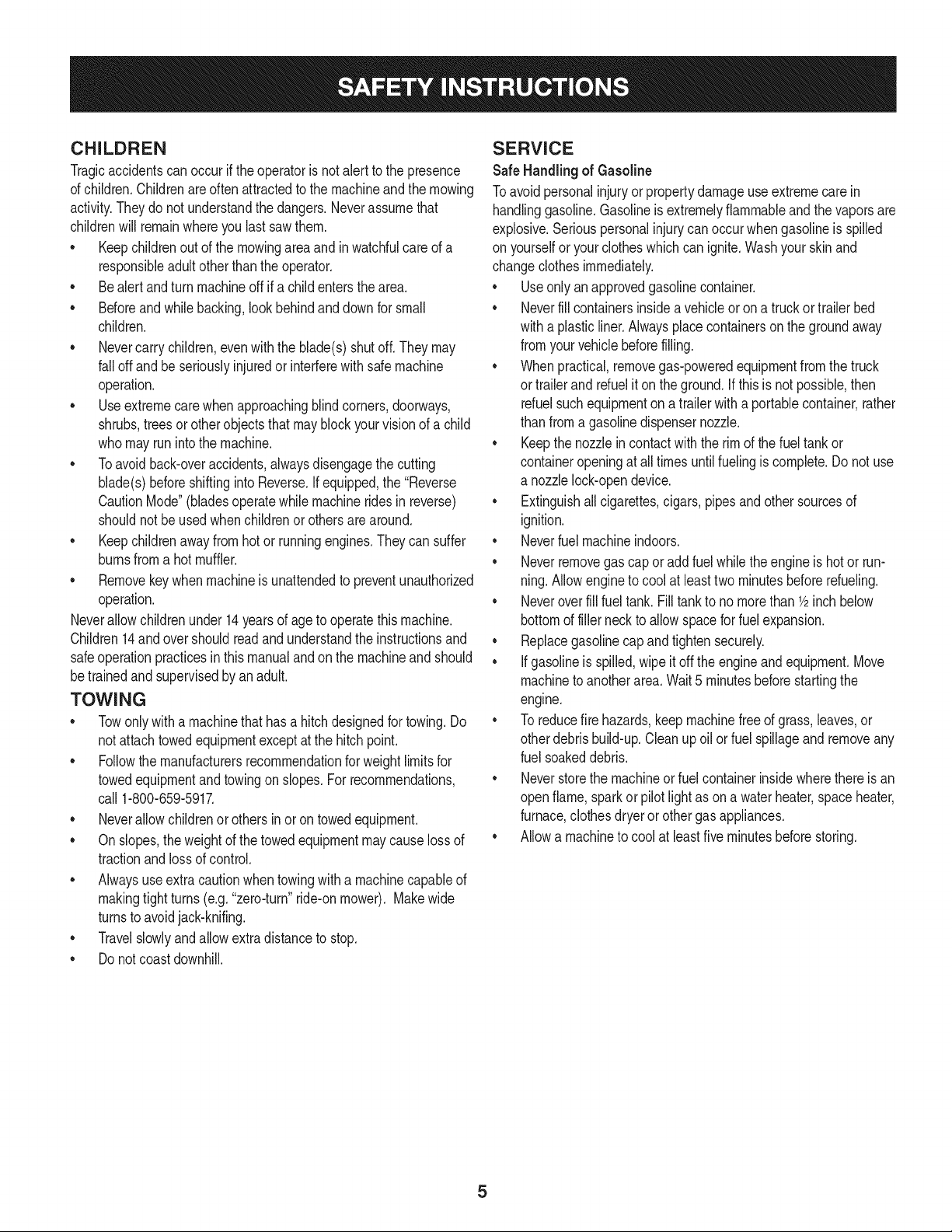
CHILDREN
Tragicaccidentscanoccurifthe operatoris notalert to the presence
of children.Childrenare often attractedto the machineandthe mowing
activity.Theydo notunderstandthe dangers.Neverassumethat
childrenwill remainwhereyou lastsawthem.
• Keepchildrenout of the mowingareaand inwatchfulcare of a
responsibleadultotherthanthe operator.
• Bealert and turnmachineoff ifa childentersthe area.
• Beforeandwhilebacking,lookbehindanddownfor small
children.
Nevercarrychildren,evenwith the blade(s)shutoff.Theymay
fall offand be seriouslyinjuredorinterferewithsafemachine
operation.
• Useextremecarewhenapproachingblind corners,doorways,
shrubs,treesorotherobjectsthatmayblockyourvisionof a child
whomayrunintothe machine.
Toavoidback-overaccidents,alwaysdisengagethe cutting
blade(s)beforeshiftingintoReverse.If equipped,the "Reverse
CautionMode"(bladesoperatewhilemachineridesinreverse)
shouldnotbe usedwhenchildrenor othersare around.
Keepchildrenawayfromhotor runningengines.Theycansuffer
burnsfroma hotmuffler.
• Removekeywhenmachineisunattendedto preventunauthorized
operation.
Neverallowchildrenunder14yearsof ageto operatethis machine.
Children14andovershouldreadandunderstandthe instructionsand
safeoperationpracticesinthismanualandon the machineand should
betrainedandsupervisedbyan adult.
TOWING
Towonlywitha machinethathasa hitchdesignedfor towing.Do
not attachtowedequipmentexceptat the hitch point.
Followthe manufacturersrecommendationforweightlimitsfor
towedequipmentandtowingonslopes.For recommendations,
call 1-800-659-5917.
Neverallowchildrenor othersin or on towedequipment.
Onslopes,theweightof thetowedequipmentmaycause lossof
tractionandlossof control.
Alwaysuseextracautionwhentowingwitha machinecapableof
makingtightturns(e.g."zero-turn"ride-onmower). Makewide
turnsto avoidjack-knifing.
Travelslowlyandallowextradistanceto stop.
Do notcoastdownhill.
SERVICE
SafeHandlingof Gasoline
Toavoidpersonalinjuryorpropertydamageuse extremecarein
handlinggasoline.Gasolineisextremelyflammableandthe vaporsare
explosive.Seriouspersonalinjurycanoccurwhengasolineis spilled
on yourselforyour clotheswhichcan ignite.Washyourskin and
changeclothesimmediately.
• Useonly anapprovedgasolinecontainer.
Neverfill containersinsidea vehicleor on a truckor trailer bed
witha plasticliner.Alwaysplacecontainerson the groundaway
fromyourvehiclebeforefilling.
Whenpractical,removegas-poweredequipmentfromthe truck
or trailerandrefueliton theground.Ifthis isnot possible,then
refuelsuchequipmentona trailerwitha portablecontainer,rather
than froma gasolinedispensernozzle.
Keepthe nozzleincontactwiththe rim of the fueltankor
containeropeningat all timesuntilfuelingiscomplete.Donot use
a nozzlelock-opendevice.
Extinguishall cigarettes,cigars,pipesandothersourcesof
ignition.
• Neverfuel machineindoors.
Neverremovegascap or add fuelwhilethe engineis hotor run-
ning.Allowengineto coolat leasttwominutesbeforerefueling.
Neveroverfill fuel tank. Filltank to no morethan 1/2inchbelow
bottomof filler neckto allowspace forfuel expansion.
• Replacegasolinecap andtightensecurely.
• Ifgasolineis spilled,wipeitoff the engineandequipment.Move
machineto anotherarea.Wait5 minutesbeforestartingthe
engine.
• To reducefire hazards,keepmachinefree of grass,leaves,or
otherdebrisbuild-up.Cleanup oil or fuel spillageandremoveany
fuel soakeddebris.
• Neverstorethe machineor fuelcontainerinsidewherethere isan
openflame,sparkor pilotlight as ona waterheater,spaceheater,
furnace,clothesdryeror othergasappliances.
Allowa machineto coolat least five minutesbeforestoring.
GeneralService
• Neverrunanengineindoorsorinapoorlyventilatedarea.Engine
exhaustcontainscarbonmonoxide,anodorless,anddeadlygas.
• Beforecleaning,repairing,orinspecting,makecertainthe
blade(s)andallmovingpartshavestopped.Disconnectthespark
plugwireandgroundagainsttheenginetopreventunintended
starting.
• Periodicallychecktomakesurethebladescometocomplete
stopwithinapproximately(5)fivesecondsafteroperatingthe
bladedisengagementcontrol.Ifthebladesdonotstopwithinthe
thistimeframe,yourmachineshouldbeservicedprofessionally
byaSearsorotherqualifiedservicedealer.
• Checkbrakeoperationfrequentlyasitissubjectedtowearduring
normaloperation.Adjustandserviceasrequired.
• Checktheblade(s)andenginemountingboltsatfrequent
intervalsforpropertightness.Also,visuallyinspectblade(s)
fordamage(e.g.,excessivewear,bent,cracked).Replacethe
blade(s)withtheoriginalequipmentmanufacturer's(O.E.M.)
blade(s)only,listedinthismanual.Useofpartswhichdonot
meettheoriginalequipmentspecificationsmayleadtoimproper
performanceandcompromisesafety!
• Mowerbladesaresharp.Wrapthebladeorweargloves,anduse
extracautionwhenservicingthem.
• Keepallnuts,bolts,andscrewstighttobesuretheequipmentis
insafeworkingcondition.
• Nevertamperwiththe safetyinterlocksystemor othersafety
devices.Checktheir properoperationregularly.
• Afterstrikinga foreignobject,stopthe engine,disconnectthe
sparkplugwire(s)and groundagainstthe engine.Thoroughly
inspectthe machinefor anydamage.Repairthe damagebefore
startingandoperating.
• Neverattemptto makeadjustmentsor repairsto the machine
whilethe engineis running.
• Grasscatchercomponentsandthe dischargecoverare subject
to wearanddamagewhichcouldexposemovingpartsor allow
objectsto bethrown.Forsafetyprotection,frequentlycheck
componentsand replaceimmediatelywithoriginalequipment
manufacturer's(O.E.M.)parts only,listed inthis manual.Useof
partswhichdo not meetthe originalequipmentspecificationsmay
leadto improperperformanceandcompromisesafety!
• Donot changethe enginegovernorsettingsorover-speedthe
engine.The governorcontrolsthe maximumsafe operatingspeed
of the engine.
Maintainor replacesafetyandinstructionlabels,as necessary.
• Observeproperdisposallawsandregulationsfor gas,oil, etc.to
protecttheenvironment.
• Accordingto the ConsumerProductsSafetyCommission(CPSC)
andthe U.S.EnvironmentalProtectionAgency(EPA),this product
has anAverageUsefulLifeof seven(7)years,or 270 hours
of operation.At the endof the AverageUsefulLife,buy anew
machineor havethe machineinspectedannuallybya Searsor
otherqualifiedservicedealerto ensurethatall mechanicaland
safetysystemsare workingproperlyandnot wornexcessively.
Failureto doso can resultin accidents,injuriesor death.
DO NOT MODIFY ENGINE
Toavoid seriousinjuryor death,do notmodifyengine in anyway.
Tamperingwiththe governorsettingcanleadto a runawayengineand
causeit to operateat unsafespeeds.Nevertamper with factorysetting
of enginegovernor.
NOTICE REGARDING EMISSIONS
Engineswhicharecertifiedto complywithCaliforniaandfederal
EPAemissionregulationsfor SORE(SmallOffRoadEquipment)are
certifiedto operateon regularunleadedgasoline,andmayinclude
the followingemissioncontrolsystems:EngineModification(EM)and
ThreeWayCatalyst(TWO)if so equipped.
SPARK ARRESTOR
Thismachineis equippedwithan internalcombustionengineand
shouldnotbe usedonor nearanyunimprovedforest-covered,
brushcoveredorgrass-coveredlandunlessthe engine'sexhaust
systemisequippedwitha sparkarrestermeetingapplicablelocalor
statelaws(if any).
Ifa sparkarresteris used,it shouldbe maintainedin effectiveworking
orderby the operator.Inthe Stateof Californiatheaboveis required
by law (Section4442of the CaliforniaPublicResourcesCode).Other
statesmayhavesimilarlaws.Federallawsapplyonfederallands.
A sparkarresterfor the mufflerisavailablethroughyournearestSears
PartsandRepairServiceCenter.
6
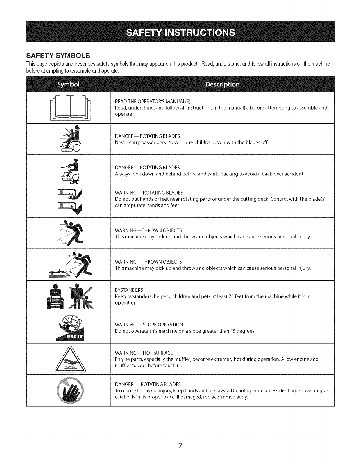
SAFETY SYMBOLS
Thispagedepictsanddescribessafetysymbolsthatmayappearon this product. Read,understand,andfollowall instructionson the machine
beforeattemptingto assembleandoperate.
0
A
READ THE OPERATOR'S MANUAL(S)
Read, understand, and follow all instructions in the manual(s) before attempting to assemble and
operate
DANGER-- ROTATING BLADES
Never carry passengers. Never carry children, even with the blades off.
DANGER-- ROTATING BLADES
Always look down and behind before and while backing to avoid a back-over accident.
WARNING-- ROTATING BLADES
Do not put hands or feet near rotating parts or under the cutting deck. Contact with the blade(s)
can amputate hands and feet.
WARNING--THROWN OBJECTS
This machine may pick up and throw and objects which can cause serious personal injury.
WARNING--THROWN OBJECTS
This machine may pick up and throw and objects which can cause serious personal injury.
BYSTANDERS
Keep bystanders, helpers, children and pets at least 75 feet from the machine while it is in
operation.
WARNING-- SLOPE OPERATION
Do not operate this machine on a slope greater than 15 degrees.
WARNING-- HOT SURFACE
Engine parts, especially the muffler, become extremely hot during operation. Allow engine and
muffler to cool before touching.
DANGER-- ROTATING BLADES
To reduce the risk of injury, keep hands and feet away. Do not operate unless discharge cover or grass
catcher is in its proper place. If damaged, replace immediately.
7
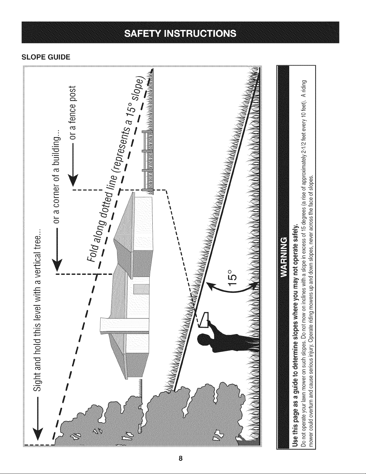
SLOPE GUIDE
}=,==
m
}====
G.)
1>
_==
oo
_==
0
c-
c_
c-
.__
U3
O
O
Nm
O
O
r_)
O
I
I
I
I
I
I
I
='-!
l
l
l
l
l
l
l
%
l
l
l
l
l
l
l
l
l
0
c
Q
0
o
o
(I)
E
o
o
L(3 0
r..- o
cz co
o
_E
o_
C2_ c__
d °
R_
X_
o o
8
WARNING
This symbol points out important safety instructions
which, if not followed, could endanger the personal
safety and/or property of yourself and others. Readand
follow all instructions in this manual before attempting
to operatethis machine. Failureto comply with these
instructions may result in personal injury. When you see
this symbol HEED ITS WARNING!
Your Responsibility
Restrictthe use of this power machineto persons who
read, understand, and follow the warnings and instruc-
tions in this manualand on the machine.
ROTATING BLADES CAUSE
SERIOUS INJURY OR DEATH
• DONOTMOWWHENCHILDRENOROTHERSARE
AROUND
• NEVERCARRYCHILDRENEVENWITHBLaDE(S)OFF.
• LOOKDOWNAND NEMDONEFORSANDWHILE
BACKING.
• MOWINGINREVERSEISNOTRECOMMENDED.
NOTE: IN BOTH MODES, WHEN OPERATOR LEAVES SEAT,
ENGINE WILL STOP UNLESS PARKING BRAKE IS SET AND
BLAINS AR_ DISEHGAGE_
9
TRACTOR SET-UP
Moving The Tractor Manually
Yourtractor'stransmissionis equippedwith a hydrostaticreliefvalve
for occasionswhenit is necessaryto movethe tractormanually.Open-
ingthisvalve permitsthe fluidin the transmissionto bypassits normal
route,allowingthe reartiresto "freewheel."Toopenthe hydrostatic
reliefvalve,proceedas follows:
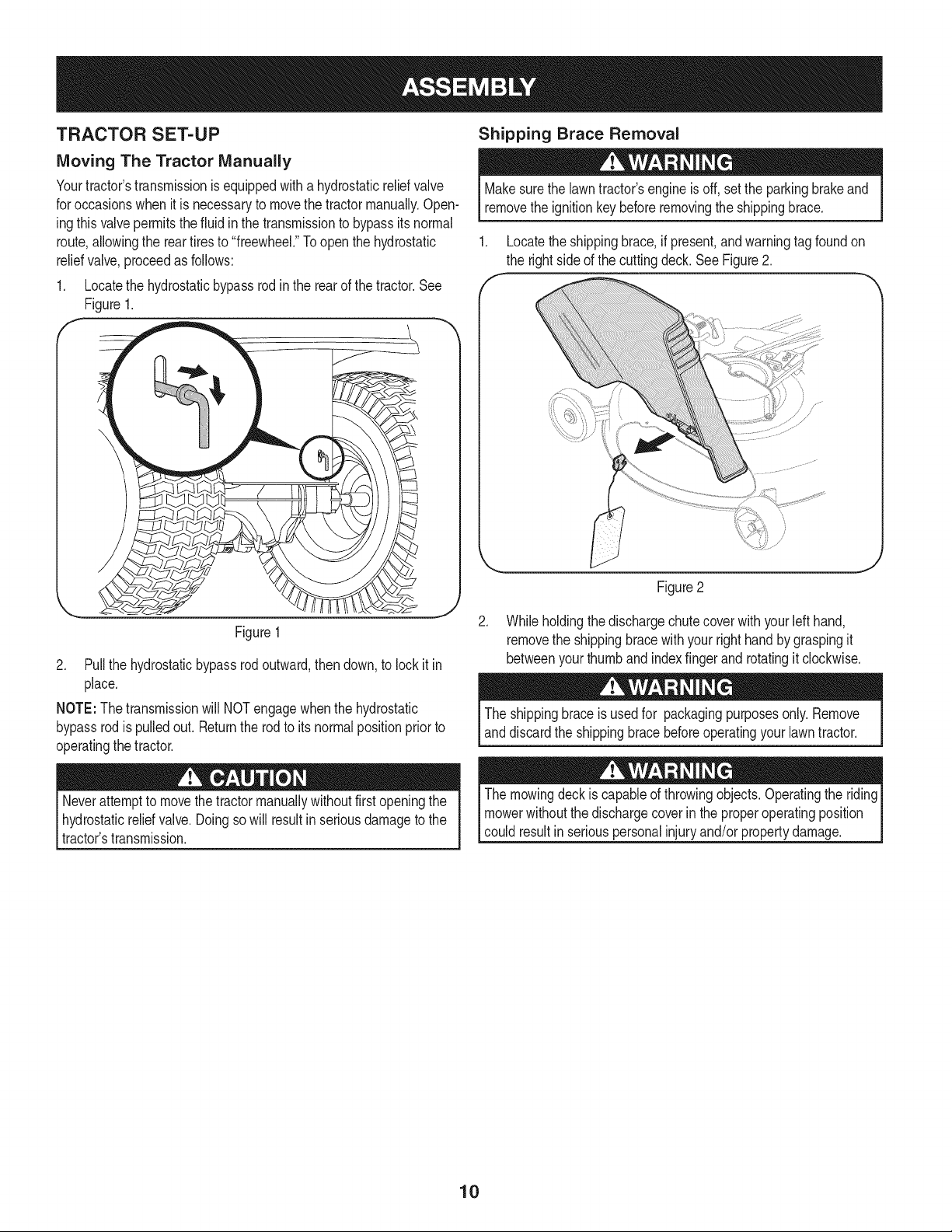
1. Locatethe hydrostaticbypassrodin the rearof thetractor.See
Figure1.
Shipping Brace Removal
Makesurethe lawntractor'sengine isoff, setthe parkingbrakeand
removethe ignitionkeybeforeremovingthe shippingbrace.
1. Locatethe shippingbrace,if present,andwarningtag foundon
the rightsideof the cuttingdeck.See Figure2.
Figure1
2. Pullthe hydrostaticbypassrodoutward,then down,to lockit in
place.
NOTE:The transmissionwill NOTengagewhenthe hydrostatic
bypassrodis pulledout. Returnthe rodto itsnormalpositionpriorto
operatingthe tractor.
.
Figure2
Whileholdingthe dischargechute coverwith yourleft hand,
removethe shippingbracewithyourright handby graspingit
betweenyourthumband indexfingerand rotatingit clockwise.
The shippingbraceis usedfor packagingpurposesonly.Remove
anddiscardthe shippingbracebeforeoperatingyour lawntractor.
Neverattemptto movethetractormanuallywithoutfirst openingthe
hydrostaticreliefvalve.Doingsowill result in seriousdamageto the
tractor'stransmission.
The mowingdeck is capableof throwingobjects. Operatingthe riding
mowerwithoutthe dischargecoverin theproperoperatingposition
could resultin seriouspersonalinjuryand/orpropertydamage.
10
CONNECTING THE BATTERY CABLES
Batteryposts,terminals,andrelatedaccessoriescontainleadand
leadcompounds,chemicalsknownto the Stateof Californiato cause
cancerandreproductiveharm.Washhandsafter handling.
Whenattachingbatterycables,alwaysconnectthe POSiTiVE(Red)
wire to its terminalfirst,followedbythe NEGATIVE(Black)wire.
Toconnectthe batterycables,proceedas follows:
NOTE:The positivebatteryterminalis markedPos.(+). The negative
batteryterminalis markedNeg.(-).
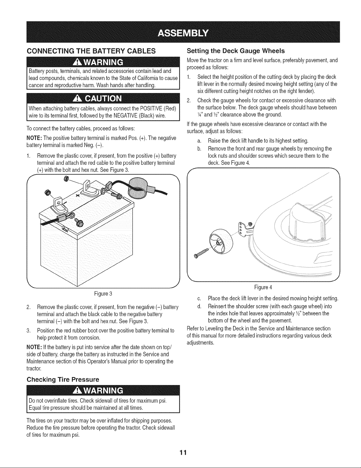
1. Removetheplasticcover,if present,fromthe positive(+)battery
terminalandattachthe redcable to the positivebatteryterminal
(+)withthe bolt andhexnut. See Figure3.
f -,
.\
Figure3
2. Removetheplasticcover,if present,fromthe negative(-) battery
terminalandattachthe black cableto the negativebattery
terminal(-) with the bolt and hex nut.SeeFigure3.
3. Positionthe redrubberbootoverthe positivebatteryterminalto
helpprotectit fromcorrosion.
NOTE: Ifthe batteryis put intoserviceafter the dateshownontop/
sided battery,chargethe batteryas instructedinthe Serviceand
Maintenancesectionof this Operator'sManualpriorto operatingthe
tractor.
Setting the Deck Gauge Wheels
Movethe tractoron a firm and levelsurface prderably pavement,and
proceedas follows:
1. Selectthe heightpositionof the cuttingdeckby placingthe deck
liftleverinthe normallydesiredmowingheightsetting(anyof the
sixdifferentcuttingheightnotcheson the rightfender).
2. Checkthe gaugewheelsfor contactor excessiveclearancewith
the surfacebelow.The deckgaugewheelsshouldhavebetween
1A"and Y2"clearanceabovethe ground.
Ifthe gaugewheelshaveexcessiveclearanceor contactwith the
surface,adjustas follows:
a. Raisethe decklift handleto itshighestsetting.
b. Removethe frontand reargauge wheelsby removingthe
locknutsandshoulderscrewswhich securethemto the
deck. SeeFigure4.
/ \
/ /
'_ j
Figure4
c. Placethe decklift leverinthe desiredmowingheightsetting.
d. Reinsertthe shoulderscrew(witheachgaugewheel)into
the indexholethat leavesapproximatelyY2"betweenthe
bottomof the wheelandthe pavement.
Referto Levelingthe Deckin the Serviceand Maintenancesection
of this manualfor moredetailedinstructionsregardingvariousdeck
adjustments.
Checking Tire Pressure
Do notoverinflatetires.Checksidewallof tires for maximumpsi.
Equaltire pressureshouldbe maintainedat alltimes.
Thetiresonyour tractormaybe over inflatedfor shippingpurposes.
Reducethetire pressurebeforeoperatingthe tractor.Checksidewall
of tiresfor maximumpsi.
11
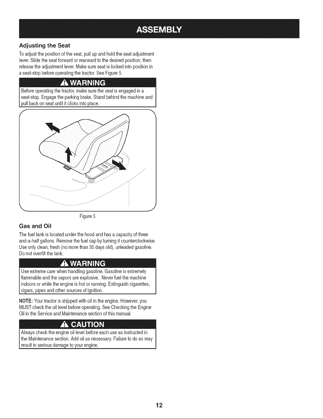
Adjusting the Seat
Toadjustthe positionof the seat,pullup andhold the seatadjustment
lever.Slidethe seatforwardor rearwardto the desiredposition;then
releasethe adjustmentlever.Makesureseatislockedintopositionin
a seat-stopbeforeoperatingthe tractor.See Figure5.
Beforeoperatingthe tractor,makesurethe seatisengagedin a
seat-stop.Engagethe parkingbrake.Standbehindthe machineand
pullbackon seatuntilitclicks intoplace.
f
Figure5
Gas and Oil
Thefuel tankis locatedunderthe hoodand hasa capacityof three
and-a-halfgallons.Removethe fuelcap by turningit counterclockwise.
Useonlyclean,fresh(no morethan 30daysold), unleadedgasoline.
Do notoverfillthe tank.
Useextremecarewhenhandlinggasoline.Gasolineis extremely
flammableandthe vaporsare explosive.Neverfuel the machine
indoorsor whilethe engineis hot or running.Extinguishcigarettes,
cigars,pipes andother sourcesof ignition.
NOTE:Yourtractoris shippedwithoil in theengine.However,you
MUSTcheckthe oil levelbeforeoperating.SeeCheckingthe Engine
Oilin the Serviceand Maintenancesectionof this manual.
Alwayschecktheengineoil levelbeforeeachuseas instructedin
the Maintenancesection.Add oil as necessary.Failureto do so may
resultin seriousdamageto yourengine.
12
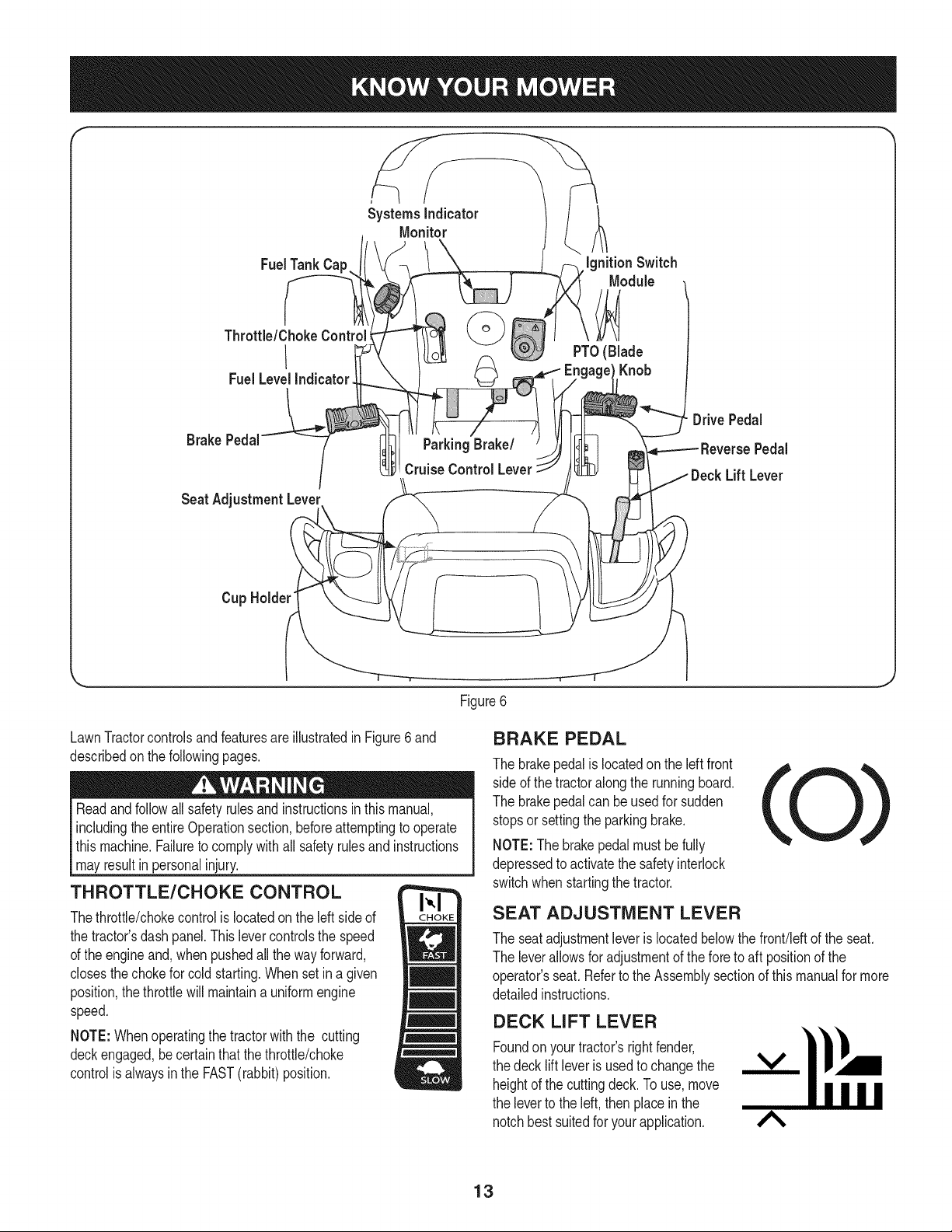
f
FueITankCap
Throttle/ChokeControl_
I
FuelLevelIndicator
IgnitionSwitch
Module
PTO(Blade
Knob
DrivePedal
Pedal
LiffLever
Cup Holder"
\
Figure6
LawnTractorcontrolsandfeaturesareillustratedinFigure6and
describedon thefollowingpages.
Readandfollowallsafetyrulesand instructionsinthis manual,
includingtheentireOperationsection,beforeattemptingto operate
this machine.Failureto complywithall safety rulesand instructions
mayresultin personalinjury.
THROTTLE/CHOKE CONTROL
Thethrottle/chokecontrolis locatedon the left sideof
the tractor'sdashpanel.This levercontrolsthe speed
of the engineand,whenpushedall the wayforward,
closesthechokefor cold starting.Whenset in a given
position,the throttlewillmaintaina uniformengine
speed.
NOTE:Whenoperatingthe tractorwith the cutting
deckengaged,becertainthatthe throttle/choke
controlis alwaysinthe FAST(rabbit)position.
BRAKE PEDAL
The brakepedalis locatedon the left front
sideof the tractoralongthe runningboard.
The brakepedalcan be usedfor sudden
stopsor settingthe parkingbrake.
NOTE:Thebrakepedalmustbefully
depressedto activatethe safetyinterlock
switchwhenstartingthe tractor.
SEAT ADJUSTMENT LEVER
The seatadjustmentleveris locatedbelowthe front!leftof the seat.
The leverallowsfor adjustmentof the foreto aft positionof the
operator'sseat. Referto the Assemblysectionof thismanualfor more
detailedinstructions.
DECK LIFT LEVER
Foundonyour tractor'srightfender,
the decklift leveris usedto changethe
heightof the cuttingdeck.To use,move
the leverto the left, thenplacein the
notchbestsuitedfor yourapplication.
A
13
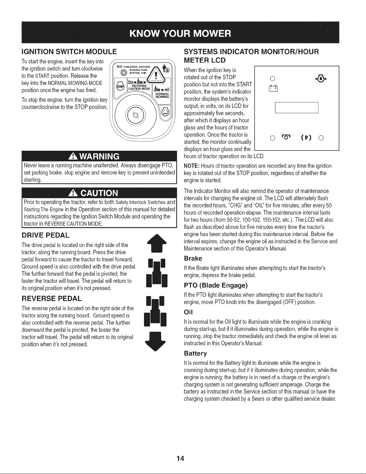
iGNiTiON SWITCH MODULE
Tostart theengine,insertthe key into
the ignitionswitchand turnclockwise
to the STARTposition.Releasethe
keyintothe NORMALMOWINGMODE
positiononcethe enginehas fired.
Tostoptheengine,turnthe ignitionkey
counterclockwiseto the STOPposition.
REVERS£PUSH
8UTTONm_
Neverleavea runningmachineunattended.AlwaysdisengagePTO,
setparkingbrake,stopengineand removekeyto preventunintended
starting.
Priorto operatingthe tractor,referto bothSafetyInterlockSwitchesand
StartingTheEnginein the Operationsectionof thismanualfor detailed
instructionsregardingthe IgnitionSwitchModuleandoperatingthe
tractorinREVERSECAUTONMODE. j
DRIVE PEDAL
Thedrivepedalis locatedon the rightsideof the
tractor,alongthe runningboard.Pressthe drive
pedalforwardto causethe tractorto travelforward.
Groundspeedis alsocontrolledwith the drivepedal.
Thefurtherforwardthat thepedalis pivoted,the
fasterthetractorwill travel.The pedalwill returnto
itsoriginalpositionwhen it's not pressed.
REVERSE PEDAL
The reversepedal is locatedonthe right sideof the
tractoralongthe runningboard. Groundspeedis
alsocontrolledwiththe reversepedal.Thefurther
downwardthe pedalis pivoted,the fasterthe
tractorwill travel.Thepedalwill returnto itsoriginal
positionwhenit's not pressed.
|
SYSTEMS INDICATOR MONITOR/HOUR
METER LCD
Whenthe ignitionkeyis
rotatedout of the STOP
positionbut not intothe START
position,thesystem'sindicator
monitordisplaysthe battery's
output,in volts,on its LCDfor
approximatelyfiveseconds,
afterwhichit displaysan hour
glassandthe hoursof tractor
operation.Oncethe tractoris
started,the monitorcontinually
displaysan hourglass and the
0
I
o (P) o
hoursof tractoroperationon itsLCD.
NOTE: Hoursof tractoroperationarerecordedanytimethe ignition
keyis rotatedout of the STOPposition,regardlessof whetherthe
engineis started.
The IndicatorMonitorwillalso remindthe operatorof maintenance
intervalsfor changingthe engineoil. The LCDwill alternatelyflash
the recordedhours,"CHG"and "OIL."for fiveminutes,after every50
hoursof recordedoperationelapse.The maintenanceintervallasts
for two hours(from50-52, 100-102,150-152,etc.).The LCDwill also
flashas describedabovefor fiveminuteseverytimethe tractor's
enginehasbeenstartedduringthismaintenanceinterval.Beforethe
intervalexpires,changethe engineoilas instructedinthe Serviceand
Maintenancesectionof thisOperator'sManual.
Brake
if the Brakelightilluminateswhenattemptingto start the tractor's
engine,depressthe brakepedal.
PTO (Blade Engage)
Ifthe PTOlight illuminateswhenattemptingto startthe tractor's
engine,movePTOknobinto thedisengaged(OFF)position.
Oil
Itis normalfor the Oil lightto illuminatewhile theengine is cranking
duringstart-up,but if it illuminatesduringoperation,whilethe engineis
running,stopthe tractorimmediatelyand checkthe engineoil levelas
instructedinthis Operator'sManual.
Battery
Itis normalfor the Batterylight to illuminatewhilethe engineis
crankingduringstart-up,but if it illuminatesduringoperation,whilethe
engineis running,the batteryis in needof a chargeorthe engine's
chargingsystemis notgeneratingsufficientamperage.Chargethe
batteryas instructedin the Servicesectionof thismanualor havethe
chargingsystemcheckedby a Searsor otherqualifiedservicedealer.
14
FUEL LEVEL INDICATOR
The FuelLevelIndicatorislocatedon the left sideof the tractor's
dashandindicatesthe amountof fuelin the gastank.
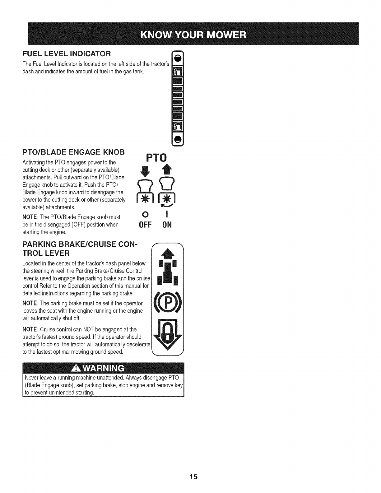
PTO/BLADE ENGAGE KNOB
Activatingthe PTOengagespowerto the
cuttingdeckorother(separatelyavailable)
attachments.Pulloutwardon the PTO/Blade
Engageknobto activateit. Pushthe PTO/
BladeEngageknobinwardto disengagethe
powerto the cuttingdeckorother (separately
available)attachments.
NOTE:The PTO/BladeEngageknobmust
be inthe disengaged(OFF)positionwhen
startingtheengine.
PTO
OFF ON
PARKING BRAKE/CRUISE CON-
TROL LEVER
Locatedinthe centerof the tractor'sdash panelbelow
the steeringwheel,the ParkingBrake/CruiseControl
leveris usedto engagethe parkingbrakeandthe cruise
controlReferto the Operationsectionof this manualfor
detailedinstructionsregardingthe parkingbrake.
NOTE:The parkingbrakemustbe setif the operator
leavesthe seatwiththe enginerunningor theengine
willautomaticallyshutoff.
NOTE:Cruisecontrolcan NOTbeengagedat the
tractor'sfastestgroundspeed.If theoperatorshould
attemptto doso, the tractorwillautomaticallydecelerate
to the fastestoptimalmowinggroundspeed.
(BladeEngageknob),setparkingbrake,stopengineand remove
to preventunintendedstarting.
15
SAFETY iNTERLOCK SWITCH ES
Thistractoris equippedwitha safetyinterlocksystemfor the protection
of the operator.Ifthe interlocksystemshouldevermalfunction,do not
operatethe tractor.Contacta Searsorotherqualifiedservicedealer.
• The safetyinterlocksystempreventstheenginefromcrankingor
startingunlessthe parkingbrakeis engaged,andthe PTO(Blade
Engage)handleis inthe disengaged(OFF)position.
Theenginewill automaticallyshut off if theoperatorleavesthe
seatbeforeengagingthe parkingbrake.
• TheelectricPTO(BladeEngage)clutchwill automaticallyshut
off if the operatorleavesthe tractor'sseatwiththe PTO(Blade
Engage)knobinthe engaged(ON) position,regardlessof
whetherthe parkingbrakeisengaged.
• Withthe ignitionkeyinthe NORMALMOWINGposition,the
electricPTO(BladeEngage)clutchwillautomaticallyshutoffif
the PTO(BladeEngage)knobis movedintothe engaged(ON)
positionwiththedrive pedalin positionfor reversetravel.
Do notoperatethe tractorif the interlocksystemis malfunctioning.
Thissystemwasdesignedfor your safetyandprotection.
STARTING THE ENGINE
NOTE: Referto theAssembly& Set-Upsectionof thismanualfor
GasolineandOilfill-up instructions.
1. Insertthe tractorkeyintothe ignitionswitchmodule.
2. Placethe PTO(BladeEngage)knobinthe disengaged(OFF)
position.
3. Engagethe tractor'sparkingbrake.
4. Activatethe chokecontrolby movingthe throttle/chokecontrolall
thewayforwardinto thechoke position.
5. Turnthe ignitionkeyclockwiseto the STARTposition.After
theenginestarts,releasethe key.Itwill returnto the NORMAL
MOWINGposition.
Do NOTholdthe keyinthe STARTpositionfor longerthan ten
secondsat a time.Doingso maycausedamageto yourengine's
electricstarter.
6. Afterthe enginestarts,deactivatethe chokecontrol.
NOTE: Do NOTleavethe chokecontrolon whileoperatingthetractor.
Doingso will resultin a "rich" fuel mixtureandcausethe engineto run
poorly.
STOPPING THE ENGINE
Ifyou strikea foreignobject,stopthe engineanddisconnectthe
sparkplugwire(s). Thoroughlyinspectthe machinefor anydamage.
Repairthedamagebeforerestartingand operating.
1. Ifthe bladesare engaged,placethe PTO/BladeEngageknobin
the disengaged(OFF) position.
2. Placethe throttlecontrolnear the SLOWposition.
3. Turnthe ignitionkeycounterclockwiseto the STOPposition.
4. Removethe keyfromthe ignitionswitchto preventunintended
starting.
DRIVING THE TRACTOR
Avoidsuddenstarts,excessivespeedand suddenstops.
Lightlypressthe brakepedalto releasethe parkingbrake.Movethe
throttleleverintothe FAST(rabbit)position.
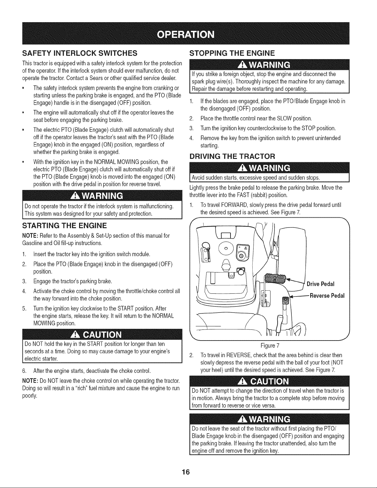
1. TotravelFORWARD,slowlypressthe drivepedalforwarduntil
the desiredspeed is achieved.See Figure7.
,
ReversePedal
Figure7
2. TotravelinREVERSE,checkthat the areabehindisclearthen
slowlydepressthe reversepedal with the ballof yourfoot(NOT
your heel)untilthe desiredspeedis achieved.See Figure7.
DoNOTattemptto changethe directionof travelwhenthetractoris
inmotion.Alwaysbringthe tractorto a completestop beforemoving
fromforwardto reverseor vice versa.
Donot leavethe seatof the tractorwithoutfirst placingthe PTO/
BladeEngageknobinthe disengaged(OFF) positionand engaging
the parkingbrake.Ifleavingthe tractorunattended,alsoturn the
engineoff andremovethe ignitionkey.
16
REVERSE CAUTION MODE
The REVERSECAUTIONMODEpositionof thekeyswitch module
allowsthe tractorto beoperatedinreversewiththe blades(PTO)
engaged.
NOTE: Mowingin reverseis not recommended.
Useextremecautionwhile operatingthe tractorin the REVERSE
CAUTIONMODE.Alwayslookdownand behindbeforeandwhile
backing.Do notoperatethe tractorwhenchildrenor othersare
around.Stopthe tractorimmediatelyif someoneentersthearea.
Touse the REVERSECAUTIONMODE:
NOTE:The operatorMUSTbe seatedin the tractorseat.
DRIVING ON SLOPES
Referto the SLOPEGUIDEon page8 to help determineslopeswhere
you mayoperatethe tractorsafely.
Donot mowon inclineswitha slopein excessof 15degrees(a rise
approximately2-1/2feet every 10feet).The tractorcouldoverturnanc
causeseriousinjury.
• Mowupanddown slopes,NEVERacross.
• Exerciseextremecautionwhenchangingdirectionon slopes.
• Watchfor holes,ruts,bumps,rocks,or otherhiddenobjects.
Uneventerraincouldoverturnthe machine.Tallgrasscan hide
obstacles.
1. Starttheengineas previouslyinstructedon the previouspage. •
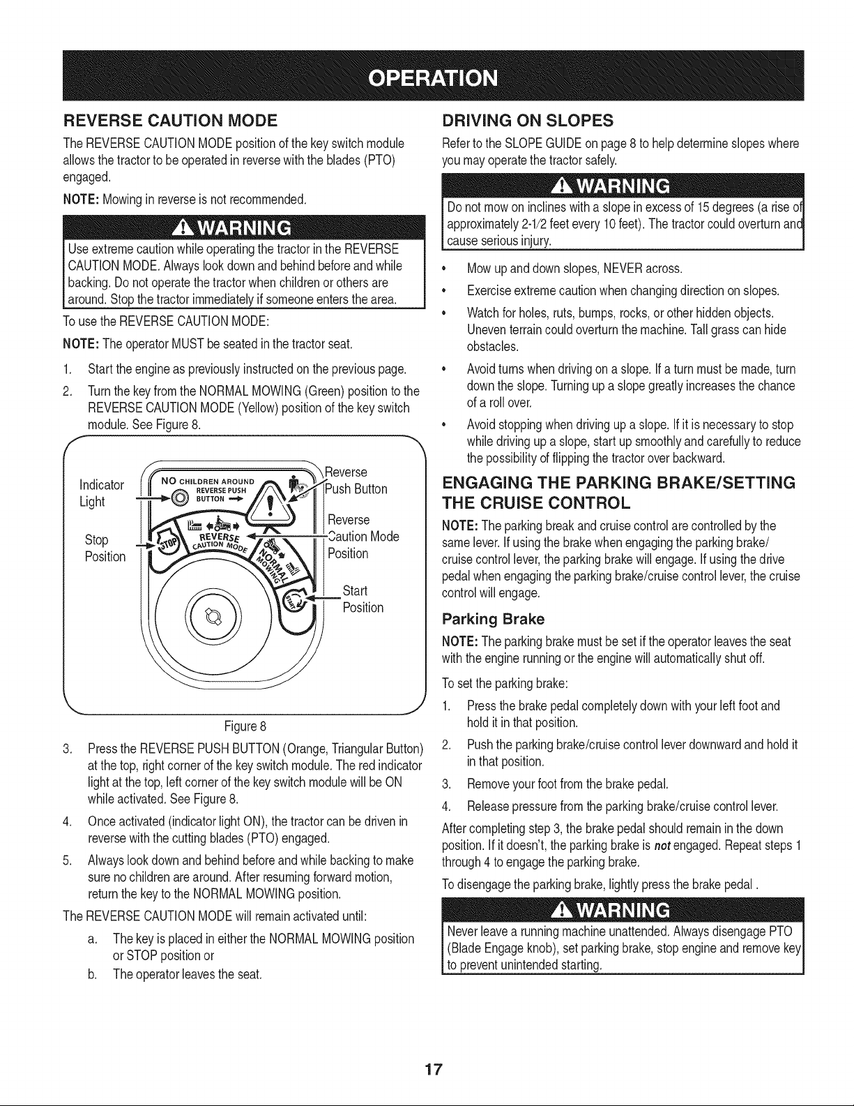
2. Turnthe keyfromthe NORMALMOWING(Green)positionto the
REVERSECAUTIONMODE(Yellow)positionof the keyswitch
module.SeeFigure8.
, _"_ Reverse
i_Push Button
II1Reverse
Mode
Position
Start
Position
Stop
Position
\ j
Figure8
3. Pressthe REVERSEPUSHBUTTON(Orange,TriangularButton)
at the top, rightcornerof the keyswitchmodule.The red indicator
lightat the top, leftcornerof the keyswitchmodulewillbe ON
whileactivated.SeeFigure8.
4. Onceactivated(indicatorlightON),the tractorcan bedrivenin
reversewiththe cuttingblades(PTO)engaged.
5. Alwayslookdownand behindbeforeandwhilebackingto make
surenochildrenarearound.Afterresumingforwardmotion,
returnthe keyto the NORMALMOWINGposition.
The REVERSECAUTIONMODEwill remainactivateduntil:
a. Thekeyis placedin eitherthe NORMALMOWINGposition
orSTOPpositionor
b. Theoperatorleavestheseat.
Avoidturnswhendrivingon a slope.If a turnmustbe made,turn
downthe slope.Turningupa slopegreatlyincreasesthe chance
of a rollover.
Avoidstoppingwhen drivingup a slope.If it is necessaryto stop
whiledrivingup a slope,start upsmoothlyand carefullyto reduce
the possibilityof flippingthe tractoroverbackward.
ENGAGING THE PARKING BRAKE/SETTING
THE CRUISE CONTROL
NOTE:Theparkingbreakandcruisecontrolarecontrolledbythe
samelever.Ifusingthe brakewhenengagingthe parkingbrake/
cruisecontrollever,theparkingbrakewillengage.Ifusingthe drive
pedalwhenengagingthe parkingbrake/cruisecontrollever,the cruise
controlwill engage.
Parking Brake
NOTE:Theparkingbrakemustbesetif theoperatorleavesthe seat
withthe engine runningor theenginewillautomaticallyshutoff.
To setthe parkingbrake:
1. Pressthe brakepedalcompletelydownwith yourleft foot and
holditinthat position.
2. Pushthe parkingbrake/cruisecontrolleverdownwardandholdit
inthatposition.
3. Removeyourfoot fromthe brakepedal.
4. Releasepressurefromthe parkingbrake/cruisecontrollever.
Aftercompletingstep3, the brakepedalshouldremaininthe down
position.If itdoesn't,the parkingbrakeisnot engaged.Repeatsteps1
through4 toengagethe parkingbrake.
Todisengagethe parkingbrake,lightly pressthe brakepedal.
(BladeEngageknob),setparkingbrake,stopengineandremove
to preventunintendedstarting.
17
Cruise Control
Neverengagethe cruise controlleverwhiletravelingin reverse.
Tosetthe cruisecontrol:
1. Slowlypressthe upperportionof thedrive pedalwithyour right
footuntilthe desiredspeedisachieved.
2. Lightlypressthe parkingbrake/cruisecontrolleverdownwardand
holdit in that position.
3. Removeyour footfrom the drive pedal.
4. Releasepressurefromthe parkingbrake/cruisecontrollever.
Aftercompletingstep3, the drivepedalshouldremaininthe down
positionandthetractorwill maintainthe sameforwardspeed.If it
doesn't,the cruisecontrolis not engaged.Repeatsteps 1through4 to
engagethecruisecontrol.
Todisengagethe cruise control,lightlypressthe drivepedalor the
brakepedal.
NOTE:Cruisecontrolcannotbesetat the tractor'sfastestground
speed.If the operatorshouldattemptto do so,thetractorwill automati-
callydecelerateto thefastestoptimalmowinggroundspeed.
Tochangethe directionof travelfromforwardto reversewhencruise
controlis engaged,pressthe brakepedalto disengagethe cruise
controlandbringthe tractorto a completestop.Thenslowlypressthe
reversepedalwiththe ball of yourfootto travel inreverse.
USING THE DECK LIFT LEVER
To raisethe cuttingdeck,movethe deck lift leverto the left,then place
it in the notchbest suitedfor yourapplication.
OPERATING THE HEADLIGHTS
The lampsareONwheneverthe ignitionkeyis rotatedout of the STOP
position.The lampsturnOFFwhenthe ignitionkeyis movedto the
STOPposition.
ENGAGING THE PTO
Engagingthe PTOtransferspowerto thecuttingdeckor other
(separatelyavailable)attachments.Toengagethe PTO:
1. Movethe Throttle/Chokecontrolleverto the FAST(rabbit)
position.
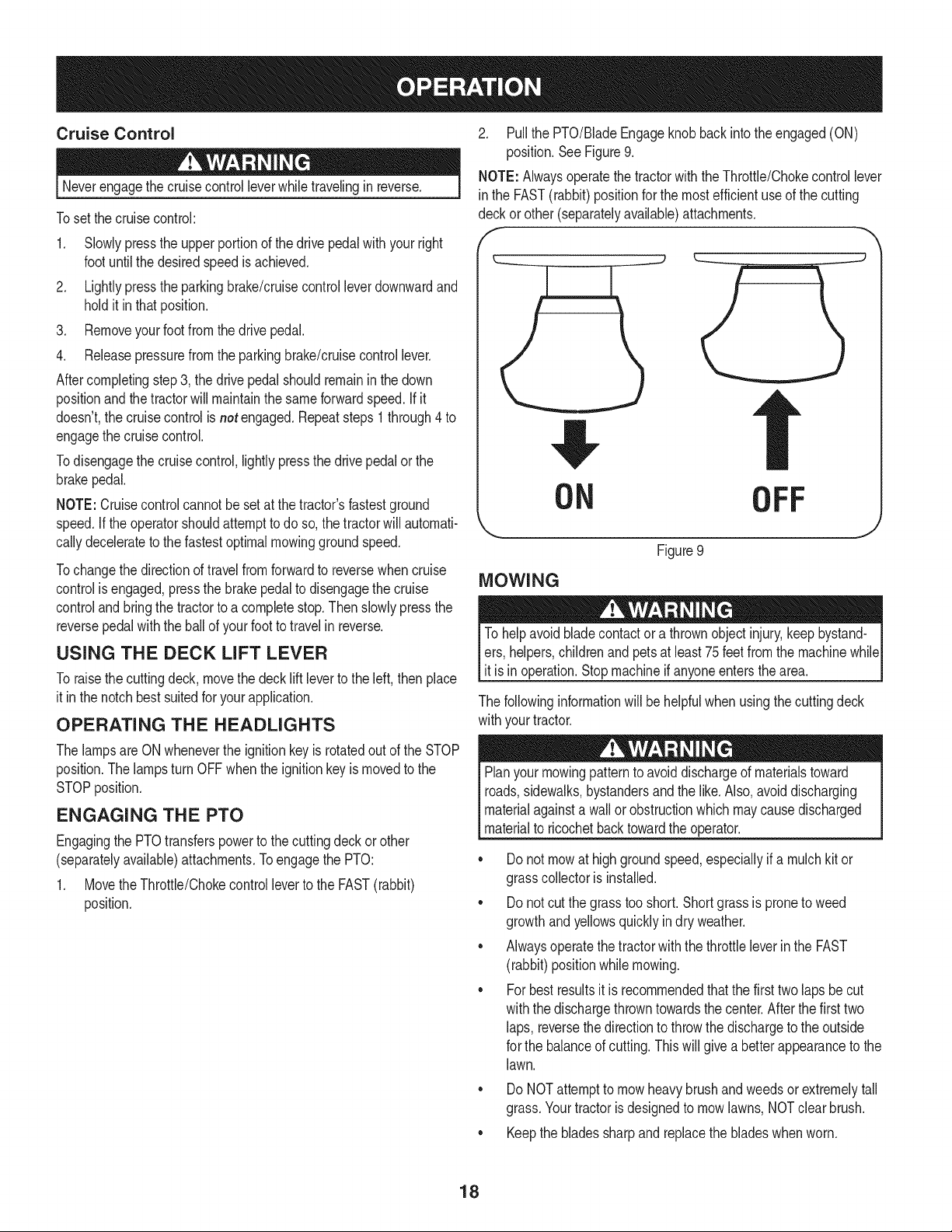
2. Pullthe PTO/BladeEngageknob backinto theengaged(ON)
position.SeeFigure9.
NOTE: Alwaysoperatethe tractorwiththe Throttle/Chokecontrollever
in the FAST(rabbit)positionfor the mostefficientuseof the cutting
deckor other(separatelyavailable)attachments.
f -,
ON OFF
Figure9
MOWING
To helpavoidbladecontactor a thrownobject injury,keepbystand-
ers,helpers,childrenand petsat least75feet from the machinewhile
it is in operation.Stopmachineif anyoneentersthe area.
The followinginformationwill behelpfulwhenusingthe cuttingdeck
withyourtractor.
Planyourmowingpatternto avoiddischargeof materialstoward
roads,sidewalks,bystandersand the like.Also,avoiddischarging
materialagainstawall or obstructionwhichmaycausedischarged
materialto ricochetbacktowardthe operator.
• Donot mowat highgroundspeed,especiallyif a mulchkit or
grasscollectoris installed.
• Donot cutthe grasstooshort. Shortgrassis proneto weed
growthandyellowsquicklyindry weather.
• Alwaysoperatethetractorwiththe throttleleverinthe FAST
(rabbit)positionwhilemowing.
• Forbestresultsit is recommendedthatthe first two laps becut
withthe dischargethrowntowardsthe center.Afterthe firsttwo
laps, reversethedirectionto throwthe dischargeto theoutside
for the balanceof cutting.This will givea betterappearanceto the
lawn.
Do NOTattemptto mowheavy brushand weedsorextremelytall
grass.Yourtractoris designedto mowlawns,NOTclearbrush.
• Keepthe bladessharpandreplacethe bladeswhenworn.
18
Beforeperforminganytypeof maintenance/service,disengageall
controlsandstoptheengine.Waituntilallmovingpartshavecometo
acompletestop.Disconnectsparkplugwireandgroundit againstthe
engineto preventunintendedstarting.Alwayswearsafetyglassesduring
operationorwhileperforminganyadjustmentsor repairs.
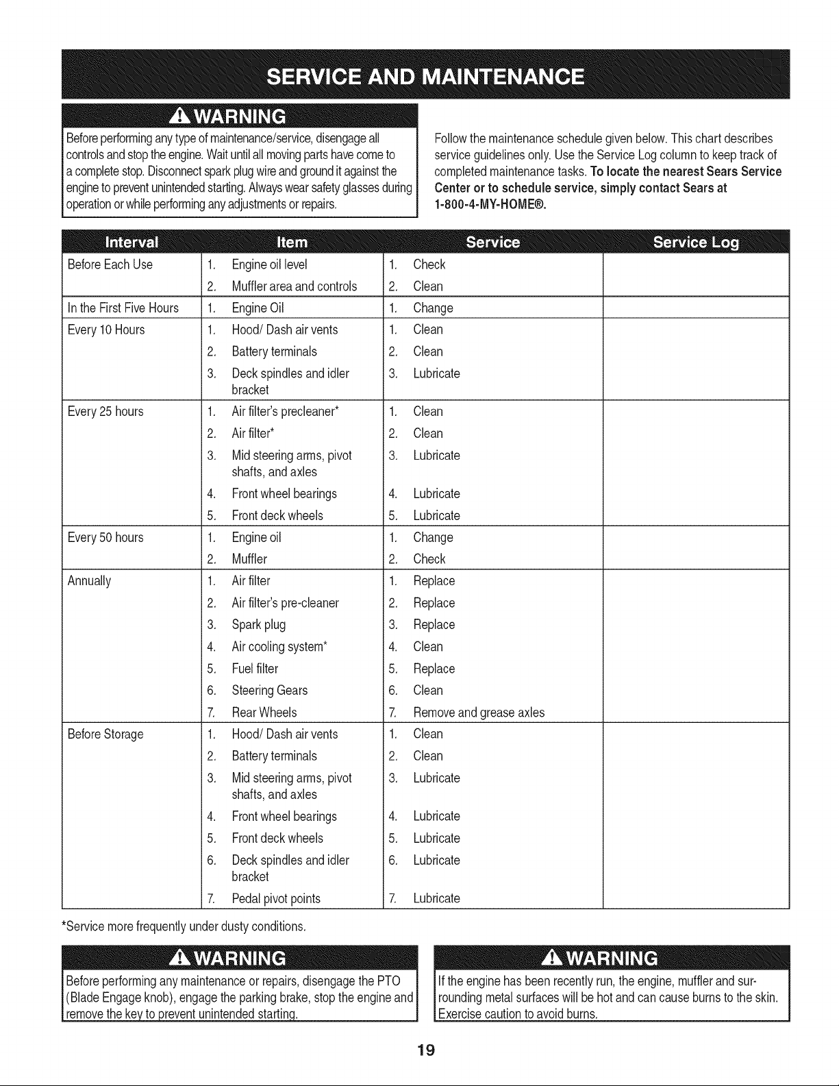
Followthe maintenanceschedulegivenbelow.Thischartdescribes
serviceguidelinesonly. Usethe ServiceLogcolumnto keeptrackof
completedmaintenancetasks.To locate the nearest Sears Service
Centeror to scheduleservice,simplycontactSears at
1-800-4-MY-HOME®.
BeforeEachUse
In the First FiveHours
Every10Hours
Every25 hours
Every50 hours
Annually
BeforeStorage
1. Engineoillevel
2. Mufflerareaandcontrols
1. EngineOil
1. Hood/Dashair vents
2. Batteryterminals
3. Deckspindlesandidler
bracket
1. Airfilter'sprecleaner*
2. Airfilter*
3. Mid steeringarms,pivot
shafts,andaxles
4. Frontwheelbearings
5. Frontdeckwheels
1. Engineoil
2. Muffler
1. Airfilter
2. Airfilter'spre-cleaner
3. Sparkplug
4. Aircoolingsystem*
5. Fuelfilter
6. SteeringGears
7. RearWheels
1. Hood/Dashair vents
2. Batteryterminals
3. Mid steeringarms,pivot
shafts,andaxles
4. Frontwheelbearings
5. Frontdeckwheels
6. Deckspindlesandidler
bracket
7. Pedalpivotpoints
1. Check
2. Clean
1. Change
1. Clean
2. Clean
3. Lubricate
1. Clean
2. Clean
3. Lubricate
4. Lubricate
5. Lubricate
1. Change
2. Check
1. Replace
2. Replace
3. Replace
4. Clean
5. Replace
6. Clean
7. Removeand greaseaxles
1. Clean
2. Clean
3. Lubricate
4. Lubricate
5. Lubricate
6. Lubricate
7. Lubricate
*Servicemorefrequentlyunderdustyconditions.
_reventunintendedstartin(
Ifthe enginehas been recentlyrun,the engine,mufflerandsur-
roundingmetalsurfaceswill be hot andcancauseburnsto the skin.
Exercisecautionto avoidburns.
19
CUTTING DECK REMOVAL
.
.
f
Placethe PTO/BladeEngageknobin the disengaged(OFF)
positionandengagethe parkingbrake.
Lowerthe deckby movingthe deck liftleverintothe bottomnotch
onthe rightfender.
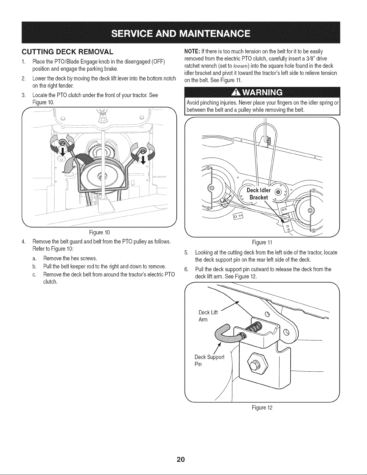
Locatethe PTOclutchunderthe frontof yourtractor.See
Figure10.
.
Figure10
Removethe beltguardand beltfromthe PTOpulleyas follows.
Referto Figure10:
a. Removethehexscrews.
b. Pullthe beltkeeperrod to the rightand downto remove.
c. Removethe deckbelt fromaroundthe tractor'selectricPTO
clutch.
NOTE: Ifthere is too muchtensionon thebelt for it to be easily
removedfromthe electricPTOclutch,carefullyinserta3/8" drive
ratchetwrench(setto loosen)intothe squareholefound inthe deck
idlerbracketand pivotit towardthe tractor'sleftside to relievetension
on the belt.See Figure11.
Avoidpinchinginjuries.Neverplaceyourfingersonthe idlerspringor
betweenthe beltanda pulleywhileremovingthe belt.
f
Figure11
5. Lookingat thecuttingdeck fromthe leftside of thetractor,locate
the decksupportpin on the rearleftsideof thedeck.
6. Pullthe decksupportpinoutwardto releasethe deck from the
decklift arm.See Figure12.
DeckLift (_
Arm
PinDeckSupport
Figure12
2O
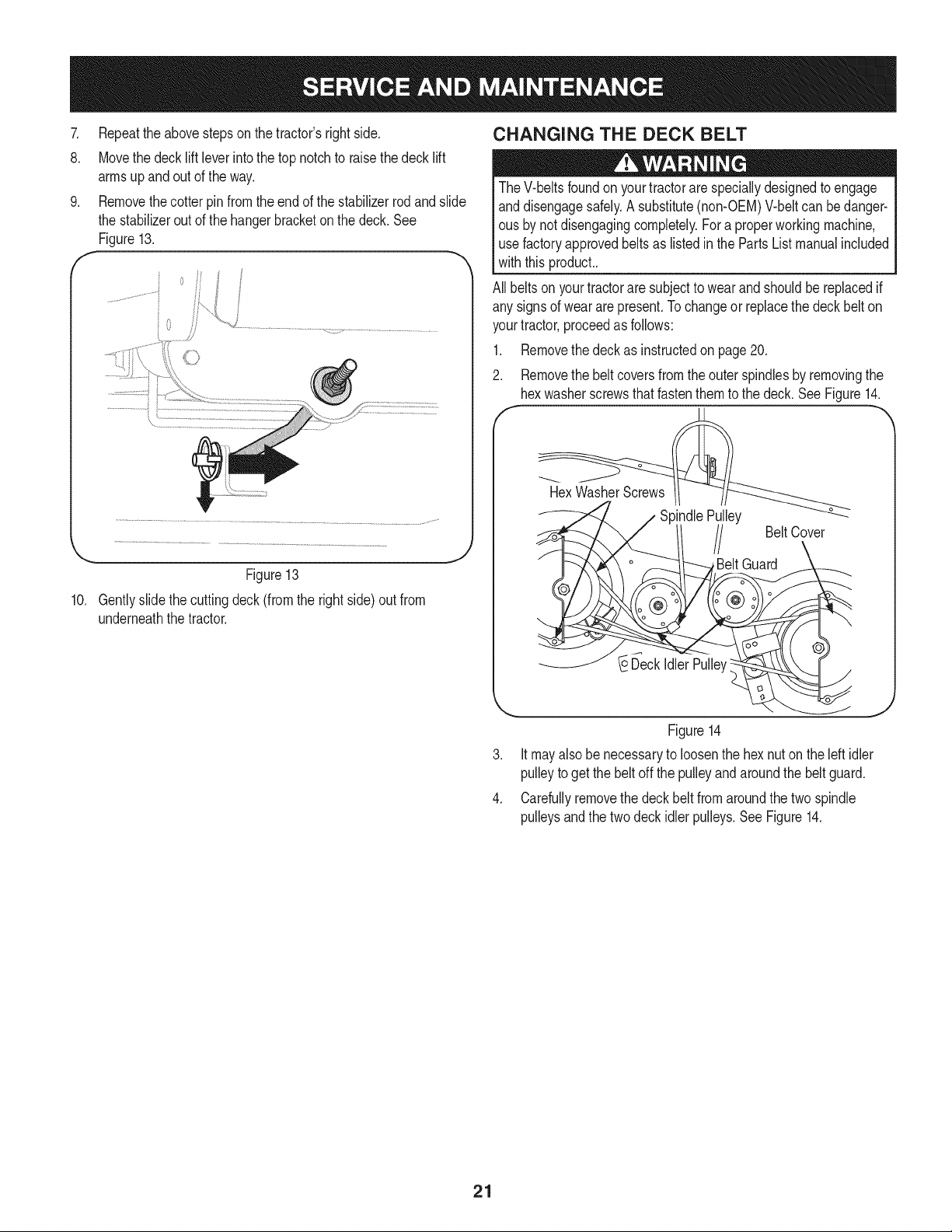
.
8.
.
f
Figure13
10. Gentlyslidethe cuttingdeck(fromthe rightside)out from
underneaththe tractor.
J
CHANGING THE DECK BELT
TheV-beltsfoundon yourtractorare speciallydesignedto engage
anddisengagesafely.A substitute(non-OEM)V-beltcan bedanger-
ous by notdisengagingcompletely.Fora properworkingmachine,
use factoryapprovedbeltsas listedin the PartsListmanualincluded
withthis product..
All beltsonyourtractorare subjectto wearandshouldbereplacedif
any signsof wear arepresent.Tochangeor replacethe deck belt on
yourtractor,proceedas follows:
1. Removethe deck as instructedon page20.
2. Removethe beltcoversfromtheouter spindlesby removingthe
hexwasherscrewsthatfastenthemto the deck.SeeFigure14.
HexWasherScrews
)indlePulley
/ BeltCover
BeltGuard
D'eckIdlerPulley:
J
Figure14
Itmayalsobe necessaryto loosenthe hexnut on the left idler
pulleyto get the beltoff the pulleyandaroundthe belt guard.
Carefullyremovethe deck belt fromaroundthe two spindle
pulleysandthe two deckidlerpulleys.See Figure14.
21
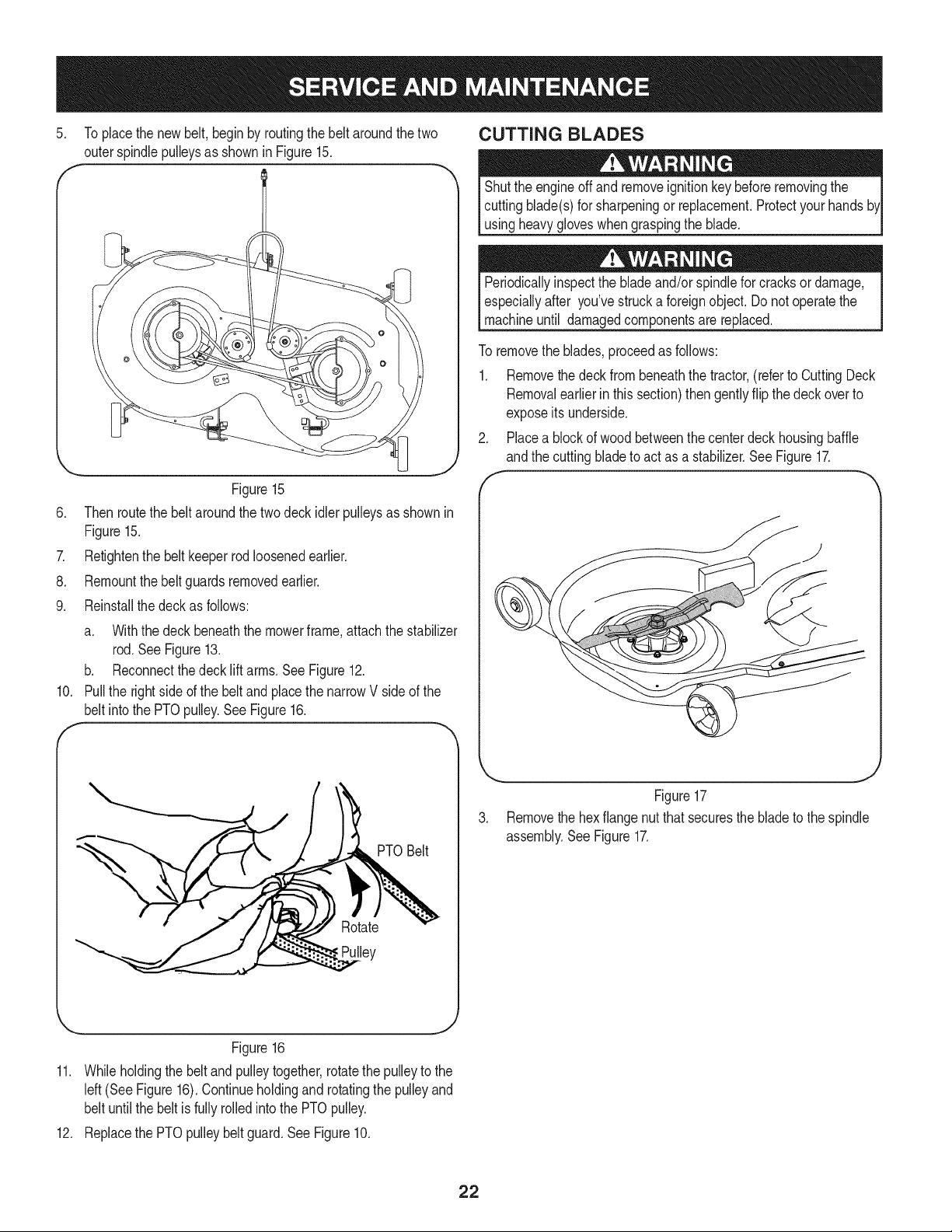
5. Toplacethe newbelt,begin by routingthe belt aroundthe two
outerspindlepulleysas shownin Figure15.
... _ J
Figure15
6. Thenroutethe beltaroundthe two deck idlerpulleysas shownin
Figure15.
7. Retightenthe belt keeperrodloosenedearlier.
8. Remountthebelt guardsremovedearlier.
9. Reinstallthe deckas follows:
a. Withthe deck beneaththe mowerframe,attachthe stabilizer
rod. SeeFigure13.
b. Reconnectthedeck liftarms.SeeFigure12.
10. Pull the rightside ofthe beltand placethe narrowV side of the
belt intothe PTOpulley.See Figure16.
!ey
CUTTING BLADES
Shutthe engineoff andremoveignitionkeybeforeremovingthe
cuttingblade(s)for sharpeningor replacement.Protectyourhands
usingheavygloveswhengraspingthe blade.
Periodicallyinspectthe bladeand/orspindlefor cracksor damage,
especiallyafter you'vestrucka foreignobject.Do notoperatethe
machineuntil damagedcomponentsarereplaced.
To removethe blades,proceedas follows:
1. Removethe deck from beneaththe tractor,(referto CuttingDeck
Removalearlierin thissection)then gentlyflip the deck overto
exposeits underside.
2. Placea blockof woodbetweenthe centerdeck housingbaffle
andthe cuttingbladeto act as a stabilizer.See Figure17.
PTOBelt
Figure17
3. Removethe hexflangenut that securesthe bladeto the spindle
assembly.SeeFigure17.
J
Figure16
11. Whileholdingthe beltandpulleytogether,rotatethepulleyto the
left(See Figure16).Continueholdingandrotatingthe pulleyand
belt untilthe beltis fully rolledinto the PTOpulley.
12. Replacethe PTOpulleybelt guard.See Figure10.
22
4. Jump Starting
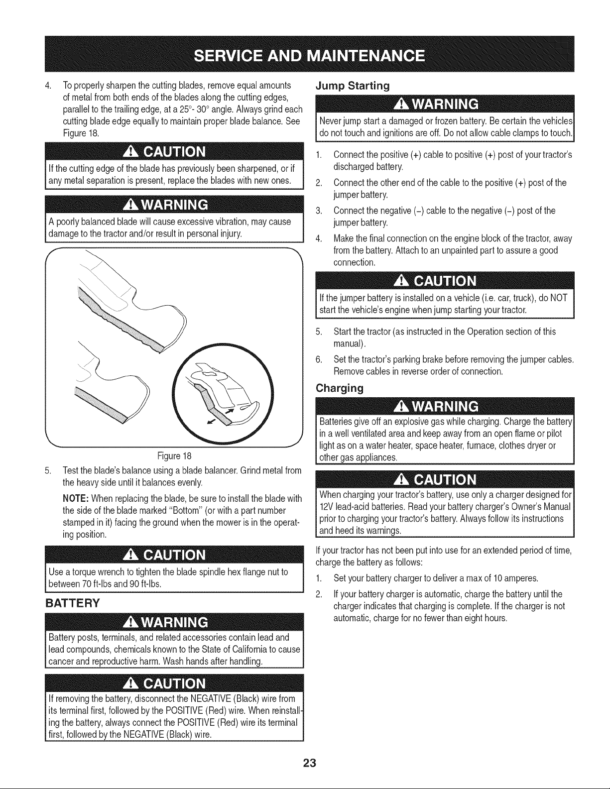
Toproperlysharpenthe cuttingblades,removeequalamounts
of metalfromboth endsof the bladesalongthe cuttingedges,
parallelto thetrailingedge,at a 250.300angle.Alwaysgrindeach
cuttingbladeedgeequallyto maintainproperbladebalance.See
Figure18.
Neverjump starta damagedor frozenbattery.Be certainthe vehicles
do nottouchandignitionsareoff. Donot allowcableclampsto touch.
Ifthe cuttingedge of the bladehas previouslybeensharpened,orif
any metalseparationis present,replacethe bladeswithnewones.
A poorlybalancedbladewillcauseexcessivevibration,maycause
damageto the tractorand/or result in personalinjury.
.
Figure18
Testthe blade'sbalanceusinga bladebalancer.Grindmetalfrom
the heavyside untilit balancesevenly.
NOTE:Whenreplacingthe blade,besureto installthe bladewith
the sideof the blademarked"Bottom" (or with a partnumber
stampedin it) facingthe groundwhenthe moweris inthe operat-
ingposition.
Useatorquewrenchto tightenthe bladespindlehexflange nutto
between70ft-lbs and 90ft-lbs.
BATTERY
Batteryposts,terminals,andrelatedaccessoriescontainleadand
leadcompounds,chemicalsknownto the Stateof Californiato cause
cancerandreproductiveharm.Washhandsafter handling.
If removingthe battery,disconnectthe NEGATIVE(Black)wirefrom
itsterminalfirst,followedby the POSITIVE(Red)wire. Whenreinstall-
ingthe battery,alwaysconnectthe POSITIVE(Red)wireits terminal
first,followedby the NEGATIVE(Black)wire.
1. Connectthe positive(+) cableto positive(+) post of yourtractor's
dischargedbattery.
2. Connectthe otherendof the cableto thepositive(+) postof the
jumperbattery.
3. Connectthe negative(-) cable to the negative(-) postof the
jumperbattery.
4. Makethefinal connectionon the engineblockof thetractor,away
fromthe battery.Attachto an unpaintedpart to assurea good
connection.
Ifthejumperbatteryis installedon a vehicle(i.e. car,truck),do NOT
start the vehicle'senginewhenjump startingyourtractor.
5. Startthe tractor(as instructedin theOperationsectionof this
manual).
6. Setthe tractor'sparkingbrakebeforeremovingthejumpercables.
Removecablesinreverseorderof connection.
Charging
Batteriesgiveoff an explosivegas whilecharging.Chargethe batteryI
in a wellventilatedareaandkeepawayfroman openflameorpilot I
lightas on a waterheater,spaceheater,furnace,clothesdryeror I
othergas appliances. ..J
Whenchargingyourtractor'sbattery,use onlya chargerdesignedfor
12Vlead-acidbatteries.Readyourbatterycharger'sOwner'sManual
priorto chargingyourtractor'sbattery.Alwaysfollow its instructions
andheeditswarnings.
Ifyourtractorhas notbeen put intouse for anextendedperiodof time,
chargethe batteryas follows:
1. Setyourbatterychargerto delivera max of 10amperes.
2. Ifyour batterychargeris automatic,chargethe batteryuntilthe
chargerindicatesthatchargingis complete.If thechargeris not
automatic,chargefor no fewer thaneighthours.
23
FUSE
Beforeservicing,repairing,or inspecting,alwaysdisengagePTO
(BladeEngageknob),setparkingbrake,stopengineand remove
to preventunintendedstarting.
Afuse is installedin yourtractor'swiringharnessto protectthe trac-
tor'selectricalsystemfromdamagecausedbyexcessiveamperage.
Ifthe electricalsystemdoesnot function,or yourtractor'senginewill
notcrank,first checkto be certainthatthe fusehasnot blown.It is
locatedunderthe hood,mountedbehindthe top of the dashpanel on
the supportbar.
Althoughmulti-viscosityoils (5W20,10W30,etc.) improvestarting
incold weather,theywill resultin increasedoilconsumptionwhen
usedabove32°RCheckyourengineoil levelmorefrequentlyto avoid
possibleenginedamagefrom runninglowon oil.
Tocheckthe engineoil, proceedas follows:
1. Ensurethatthetractoris on a levelsurface.
2. Cleanthe oilfill areaof any debris.
3. Removethe dipstickandwipewitha cleancloth.
4. Insertandtightendipstick.
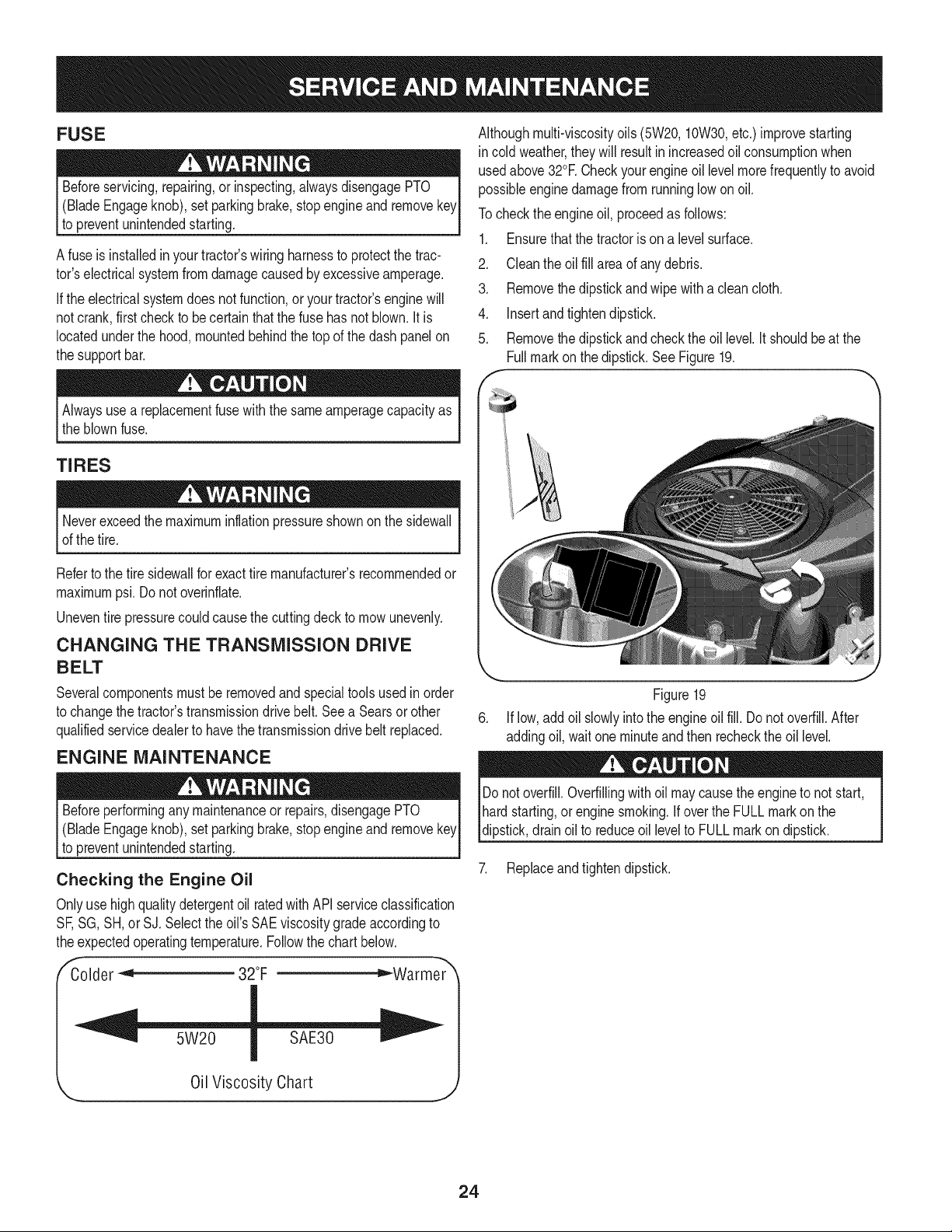
5. Removethe dipstickandcheckthe oil level.It shouldbeat the
Fullmarkon thedipstick.SeeFigure19.
Alwaysusea replacementfuse withthe sameamperagecapacityas
the blownfuse.
TIRES
Neverexceedthe maximuminflationpressureshownon the sidewall
of thetire.
Referto the tire sidewallfor exacttire manufacturer'srecommendedor
maximumpsi. Donot overinfiate.
Uneventire pressurecouldcause thecuttingdeckto mowunevenly.
CHANGING THE TRANSMISSION DRIVE
BELT
Severalcomponentsmustberemovedandspecialtoolsusedin order
to changethe tractor'stransmissiondrive belt.Seea Searsor other
qualifiedservicedealerto havethe transmissiondrivebelt replaced.
ENGINE MAINTENANCE
Beforeperformingany maintenanceor repairs,disengagePTO
(BladeEngageknob),setparkingbrake,stopengineand remove
to preventunintendedstarting.
Checking the Engine Oil
Onlyuse highqualitydetergentoil ratedwith APIserviceclassification
SF,SG,SH,or SJ.Selectthe oil's SAEviscositygradeaccordingto
theexpectedoperatingtemperature.Followthe chartbelow.
,E _Warmer_
Colder _ 32°F
Figure19
6. Iflow,addoil slowlyintothe engineoil fill. Donot overfill.After
addingoil, waitone minuteand then recheckthe oil level.
Do notoverfill.Overfillingwithoil maycausethe engineto not start,
hardstarting,or enginesmoking.Ifoverthe FULLmarkonthe
dipstick,drainoilto reduceoil levelto FULLmarkon dipstick.
7. Replaceandtightendipstick.
5W20
Oil Viscosity Chart
24
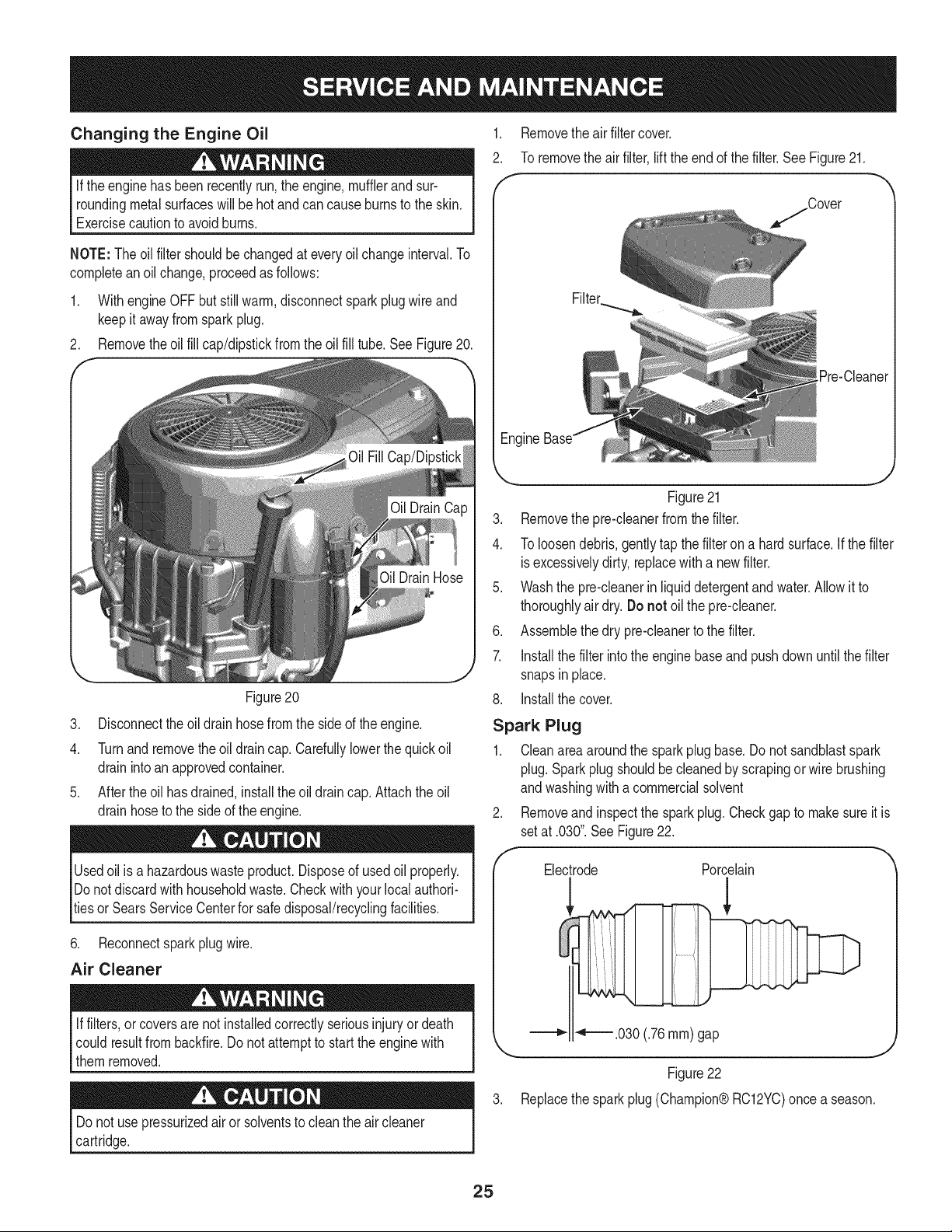
Changing the Engine Oil
Ifthe enginehas been recentlyrun,the engine,mufflerandsur-
roundingmetalsurfaceswill be hotandcan causeburnsto the skin.
Exercisecautionto avoidburns.
NOTE:The oilfilter shouldbe changedat every oilchangeinterval.To
completeanoilchange,proceedasfollows:
1. WithengineOFFbutstillwarm,disconnectspark plugwire and
keepit awayfromspark plug.
2. Removetheoil fill cap/dipstickfromthe oil fill tube.See Figure20.
Figure20
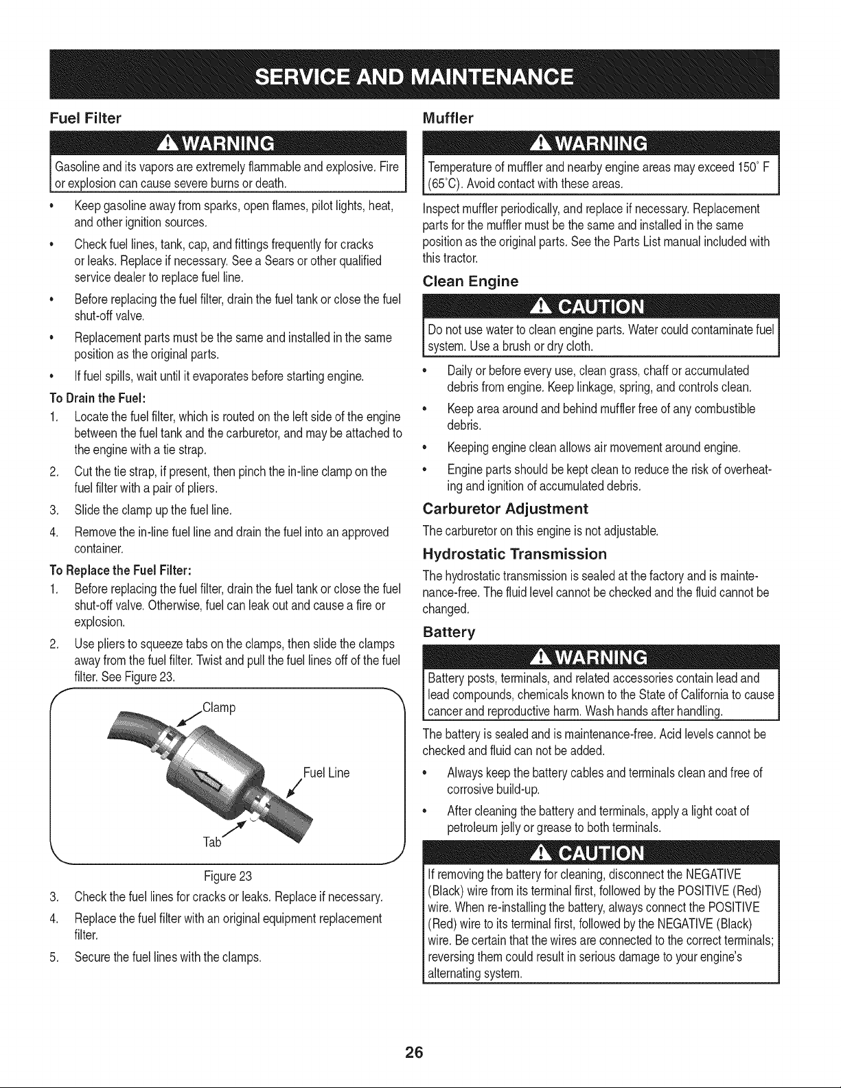
.
2.
f
Removethe air filter cover.
To removethe airfilter,lift theendof the filter.SeeFigure21.
/Cover
[Pre-Cleaner
Engine
3. Disconnectthe oil drainhosefromthe side of theengine.
4. Turnand removethe oildraincap. Carefullylowerthe quickoil
drainintoanapprovedcontainer.
5. Aftertheoil hasdrained,installthe oil drain cap. Attachthe oil
drainhoseto the sideof the engine.
Usedoil is a hazardouswasteproduct.Disposeof usedoil properly.
Donotdiscardwith householdwaste.Checkwithyourlocalauthori-
tiesor SearsServiceCenterfor safedisposal/recyclingfacilities.
6. Reconnectsparkplugwire.
Air Cleaner
Iffilters,or coversare not installedcorrectlyseriousinjuryor death
could resultfrombackfire.Do notattemptto startthe enginewith
them removed.
Do notuse pressurizedairor solventsto cleanthe air cleaner
cartridge.
k_ j
Figure21
3. Removethe pre-cleanerfromthe filter.
4. To loosendebris,gentlytap thefilterona hardsurface.If thefilter
isexcessivelydirty, replacewitha newfilter.
5. Washthe pre-cleanerinliquiddetergentandwater.Allowit to
thoroughlyair dry.Do not oil the pre-cleaner.
6. Assemblethe dry pre-cleanerto the filter.
7. Installthe filterintothe enginebaseand pushdownuntilthe filter
snapsinplace.
8. Installthe cover.
Spark Plug
1. Cleanareaaroundthe sparkplugbase.Donot sandblastspark
plug.Sparkplugshouldbecleanedby scrapingor wirebrushing
andwashingwitha commercialsolvent
2. Removeand inspectthe sparkplug.Checkgapto makesureit is
setat .030".SeeFigure22.
Electrode Porcelain
!
_'4"====.030(.76ram)gap
Figure22
3. Replacethe sparkplug(Champion@RC12YC)oncea season.
25
Fuel Filter IVluffler
Gasolineand itsvaporsareextremelyflammableandexplosive.Fire
orexplosioncan causesevereburnsor death.
• Keepgasolineawayfrom sparks,openflames,pilotlights,heat,
andotherignitionsources.
• Checkfuel lines,tank,cap,andfittingsfrequentlyforcracks
or leaks.Replaceif necessary.See a Searsor otherqualified
servicedealerto replacefuel line.
• Beforereplacingthe fuelfilter,drainthe fueltankor closethe fuel
shut-offvalve.
• Replacementpartsmustbethe sameand installedin the same
positionas theoriginalparts.
• Iffuel spills,wait until it evaporatesbeforestartingengine.
To Drainthe Fuel:
1. Locatethe fuelfilter,whichis routedon the left sideof the engine
betweenthe fuel tankandthecarburetor,and may beattachedto
theenginewitha tie strap.
2. Cutthe tie strap,if present,then pinchthe in-lineclampon the
fuelfilterwitha pair of pliers.
3. Slidethe clampup the fuel line.
4. Removethe in-linefuel lineand drainthe fuel intoan approved
container.
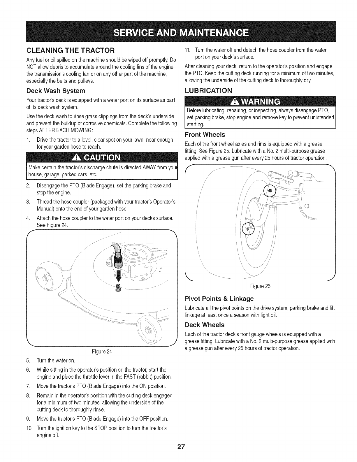
To Replacethe Fuel Filter:
1. Beforereplacingthe fuelfilter,drainthe fueltankor closethe fuel
shut-offvalve.Otherwise,fuel can leakout and causea fire or
explosion.
2. Usepliersto squeezetabs on the clamps,then slidethe clamps
awayfromthefuel filter.Twistand pullthefuel linesoff of the fuel
filter.SeeFigure23.
f
FuelLine
.
4.
.
7
,,,..,., ,,J
Figure23
Checkthe fuel linesfor cracksor leaks.Replaceif necessary.
Replacethe fuel filterwithan originalequipmentreplacement
filter.
Securethe fuel lineswiththe clamps.
Temperatureof mufflerand nearbyengineareasmayexceed150° F
(65°0).Avoidcontactwiththeseareas.
Inspectmufflerperiodically,andreplaceif necessary.Replacement
partsfor the mufflermustbethe sameand installedin the same
positionas the originalparts.See the PartsList manualincludedwith
thistractor.
Clean Engine
Donot usewaterto clean engineparts.Watercouldcontaminatefuel
system.Usea brushor dry cloth.
Dailyor beforeeveryuse,cleangrass,chaffor accumulated
debrisfromengine.Keeplinkage,spring,andcontrolsclean.
Keepareaaroundand behindmufflerfreeof anycombustible
debris.
Keepingenginecleanallowsair movementaroundengine.
• Enginepartsshouldbekept cleanto reducethe risk of overheat-
ing andignitionof accumulateddebris.
Carburetor Adjustment
The carburetoron this engineis notadjustable.
Hydrostatic Transmission
The hydrostatictransmissionis sealedat thefactory and is mainte-
nance-free.The fluidlevelcannot be checkedandthe fluidcannot be
changed.
Battery
Batteryposts,terminals,and relatedaccessoriescontainleadand
leadcompounds,chemicalsknownto the Stateof Californiato cause
cancerand reproductiveharm.Washhandsafterhandling.
The batteryis sealedand is maintenance-free.Acidlevelscannotbe
checkedandfluid can notbe added.
Alwayskeepthe batterycablesandterminalscleanandfree of
corrosivebuild-up.
• Aftercleaningthe batteryandterminals,applya lightcoatof
petroleumjelly or greaseto bothterminals.
Ifremovingthe batteryfor cleaning,disconnectthe NEGATIVE
(Black)wirefromits terminalfirst, followedby the POSITIVE(Red)
wire.Whenre-installingthe battery,alwaysconnectthe POSITIVE
(Red)wire to its terminalfirst,followedbythe NEGATIVE(Black)
wire.Becertainthatthe wiresareconnectedto thecorrectterminals;
reversingthemcouldresultinseriousdamageto yourengine's
alternatingsystem.
26
CLEANING THE TRACTOR
Anyfuel oroil spilledon the machineshouldbe wipedoff promptly.Do
NOTallowdebristo accumulatearoundthecoolingfins of the engine,
the transmission'scoolingfanor onany otherpartof themachine,
especiallythebeltsandpulleys.
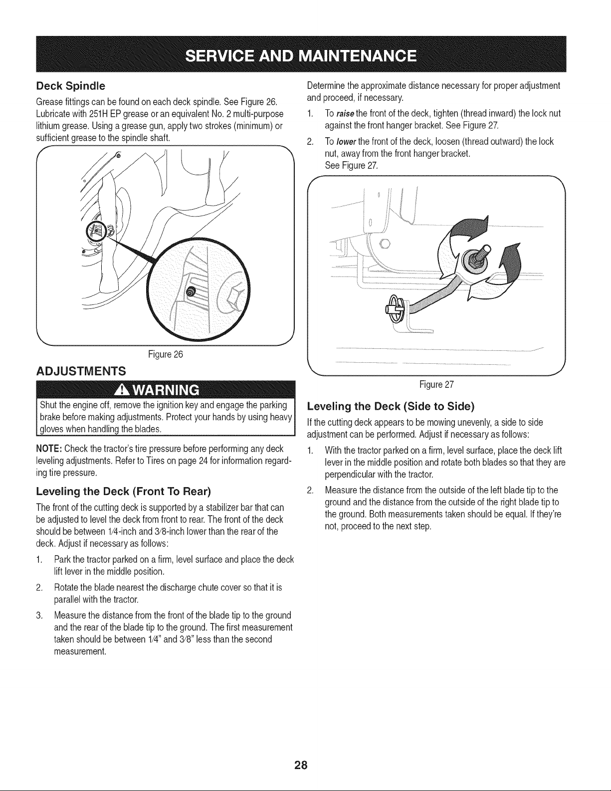
Deck Wash System
Yourtractor'sdeckis equippedwith a waterporton its surfaceas part
of its deckwashsystem.
Usethedeckwash to rinsegrassclippingsfromthe deck'sunderside
andpreventthe buildupof corrosivechemicals.Completethe following
stepsAFTEREACHMOWING:
1. Drivethe tractorto a level,clearspot onyour lawn,nearenough
for yourgardenhoseto reach.
Makecertainthe tractor'sdischargechuteis directedAWAYfromyour
house,garage,parkedcars,etc.
2. Disengagethe PTO(BladeEngage),setthe parkingbrakeand
stoptheengine.
3. Threadthe hosecoupler(packagedwithyourtractor'sOperator's
Manual)ontothe endof yourgardenhose.
4. Attachthe hosecouplerto the waterport on yourdecks surface.
SeeFigure24.
Figure24
5. Turnthe wateron.
6. Whilesittingin theoperator'spositiononthe tractor,startthe
engineandplacethe throttleleverin the FAST(rabbit)position.
7. Movethe tractor'sPTO(BladeEngage)intothe ONposition.
8. Remaininthe operator'spositionwith thecuttingdeck engaged
for a minimumof two minutes,allowingthe undersideof the
cuttingdeckto thoroughlyrinse.
9. Movethe tractor'sPTO(BladeEngage)intothe OFFposition.
10. Turnthe ignitionkeyto the STOPpositionto turnthe tractor's
engineoff.
11. Turnthewater off anddetachthehose couplerfromthe water
portonyour deck'ssurface.
Aftercleaningyourdeck, returnto the operator'spositionandengage
the PTO.Keepthe cuttingdeckrunningfor a minimumof two minutes,
allowingthe undersideof the cuttingdeck to thoroughlydry.
LUBRICATION
Beforelubricating,repairing,orinspecting,alwaysdisengagePTO,
set parkingbrake,stopengineandremovekeyto preventunintended
starting.
Front Wheels
Eachof thefrontwheelaxlesandrimsis equippedwith a grease
fitting.SeeFigure25. Lubricatewitha No.2 multi-purposegrease
appliedwitha greasegunafterevery25 hoursof tractoroperation.
\
Figure25
Pivot Points & Linkage
Lubricateallthe pivot pointsonthe drivesystem,parkingbrakeandlift
linkageat leastonce a seasonwithlightoil.
Deck Wheels
Eachof thetractordeck'sfrontgaugewheelsisequippedwith a
greasefitting.Lubricatewitha No.2 multi-purposegreaseappliedwith
a greasegunafterevery25 hoursof tractoroperation.
27
Deck Spindle
Greasefittingscan be foundon eachdeck spindle.SeeFigure26.
Lubricatewith251HEPgreaseoran equivalentNo.2 multi-purpose
lithiumgrease.Usinga greasegun, applytwostrokes(minimum)or
sufficientgreaseto the spindleshaft.
ADJUSTMENTS
Figure26
Shutthe engineoff, removethe ignitionkeyandengagethe parking
brakebeforemakingadjustments.Protectyour handsby usingheavy
gloveswhenhandlingthe blades.
NOTE:Checkthe tractor'stire pressurebeforeperforminganydeck
levelingadjustments.Referto Tires on page24 for informationregard-
ingtire pressure.
Leveling the Deck (Front To Rear)
Thefrontof the cuttingdeckis supportedby a stabilizerbarthatcan
beadjustedto levelthe deckfrom frontto rear.Thefrontof the deck
shouldbebetween1/4-inchand3/8-inchlowerthanthe rear of the
deck.Adjustif necessaryas follows:
1. Parkthe tractorparkedona firm,level surfaceandplacethe deck
lift leverinthe middleposition.
2. Rotatethe bladenearestthe dischargechute coverso thatit is
parallelwiththe tractor.
3. Measurethe distancefromthe frontof the bladetip to the ground
andthe rear of the bladetip to the ground.The firstmeasurement
takenshouldbebetween1/4"and 3/8" lessthan the second
measurement.
Determinetheapproximatedistancenecessaryfor properadjustment
and proceed,if necessary.
1. To raisethe frontof the deck,tighten(threadinward)the locknut
againstthe fronthangerbracket.See Figure27.
2. To lowerthe frontof the deck,loosen(threadoutward)the lock
nut,awayfromthe front hangerbracket.
See Figure27.
f
Figure27
J
Leveling the Deck (Side to Side)
Ifthe cuttingdeck appearsto be mowingunevenly,a sideto side
adjustmentcan be performed.Adjustif necessaryas follows:
1. Withthe tractorparkedona firm, levelsurface,placethe decklift
leverin the middlepositionand rotatebothbladesso that theyare
perpendicularwiththe tractor.
2. Measurethedistancefromthe outsideof the left bladetip to the
groundandthe distancefromthe outsideof the rightbladetip to
the ground.Bothmeasurementstakenshouldbeequal.Ifthey're
not, proceedto the nextstep.
28
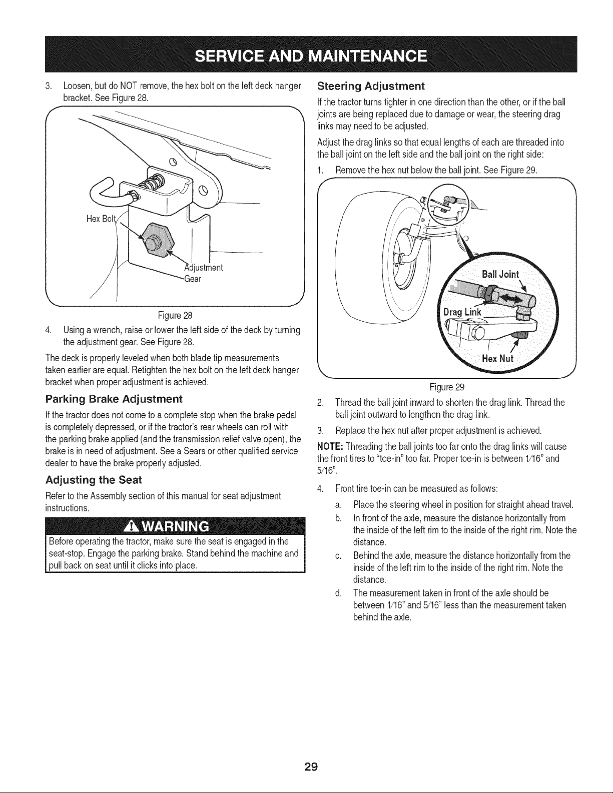
3. Loosen,butdo NOTremove,the hexbolt onthe left deck hanger
bracket.SeeFigure28.
f
Hex Bolt
ustment
-Gear
Figure28
4. Usinga wrench,raiseor lowerthe left side of thedeck byturning
the adjustmentgear.SeeFigure28.
Thedeckis properlyleveledwhenbothblade tip measurements
takenearlierareequal. Retightenthe hexbolt onthe leftdeckhanger
bracketwhenproperadjustmentis achieved.
Parking Brake Adjustment
If thetractordoes notcometo acompletestopwhenthe brakepedal
is completelydepressed,or if the tractor'srearwheelscan rollwith
the parkingbrakeapplied(andthe transmissionreliefvalveopen),the
brakeis in needof adjustment.Seea Searsorother qualifiedservice
dealerto havethe brakeproperlyadjusted.
Adjusting the Seat
Referto the Assemblysectionof thismanualfor seatadjustment
instructions.
Beforeoperatingthe tractor,makesurethe seatis engagedin the
seat-stop.Engagethe parkingbrake.Standbehindthe machineand
pullbackon seat untilit clicksinto place.
Steering Adjustment
Ifthe tractorturnstighter in onedirectionthanthe other,or if the ball
jointsarebeingreplaceddue to damageorwear,the steeringdrag
linksmayneedto beadjusted.
Adjustthedraglinksso thatequallengthsof each arethreadedinto
the balljoint onthe left sideand the balljoint on the rightside:
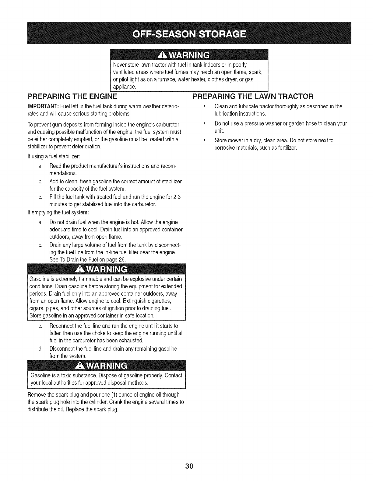
1. Removethe hexnut belowthe balljoint. SeeFigure29.
J
Figure29
2. Threadthe balljoint inwardto shortenthe drag link. Threadthe
balljoint outwardto lengthenthe draglink.
3. Replacethe hexnut afterproperadjustmentis achieved.
NOTE:Threadingthe ball joints toofar ontothe draglinkswillcause
the fronttires to "toe-in"too far.Propertoe-inis between1/16"and
5/16".
4. Fronttire toe-incan be measuredas follows:
a. Placethe steeringwheel inpositionfor straightaheadtravel.
b. Infrontof the axle, measurethe distancehorizontallyfrom
the insideof the left rimto the insideof the right rim.Notethe
distance.
c. Behindthe axle,measurethe distancehorizontallyfromthe
insideof the left rimto the insideof the rightrim.Notethe
distance.
d. The measurementtakeninfrontof the axle shouldbe
between1/16"and 5/16"lessthan themeasurementtaken
behindthe axle.
29
Neverstorelawntractorwithfuelin tankindoorsor in poorly
ventilatedareaswherefuel fumesmay reachan openflame,spark,
or pilot lightas on a furnace,waterheater,clothesdryer,or gas
appliance,
PREPARING THE ENGINE
IMPORTANT:Fuelleftin the fueltank duringwarmweatherdeterio-
ratesandwill cause seriousstartingproblems.
Topreventgum depositsfromforminginsidetheengine'scarburetor
andcausingpossiblemalfunctionof the engine,the fuel systemmust
beeithercompletelyemptied,or thegasolinemustbetreatedwitha
stabilizerto preventdeterioration.
If usingafuel stabilizer:
a. Readthe productmanufacturer'sinstructionsand recom-
mendations.
b. Addto clean,freshgasolinethe correctamountof stabilizer
for thecapacityof the fuel system.
c. Fill thefuel tank with treatedfueland run theenginefor 2-3
minutesto get stabilizedfuel intothe carburetor.
If emptyingthefuel system:
a. Do notdrainfuel whentheengine is hot.Allowtheengine
adequatetimeto cool. Drainfuel intoan approvedcontainer
outdoors,awayfromopenflame.
b. Drainany largevolumeof fuelfrom the tankby disconnect-
ingthe fuel linefromthe in-line fuelfilter neartheengine.
SeeToDrainthe Fuelon page 26.
Gasolineis extremelyflammableandcan beexplosiveundercertain
conditions.Draingasolinebeforestoringtheequipmentfor extended
periods.Drainfuelonly intoan approvedcontaineroutdoors,away
fromanopenflame.Allowengineto cool. Extinguishcigarettes,
cigars,pipes,andother sourcesof ignitionpriorto drainingfuel.
Storegasolinein an approvedcontainerin safelocation.
c. Reconnectthe fuellineand run theengine untilit startsto
falter,then usethe choketo keepthe engine runninguntilall
fuelin the carburetorhasbeen exhausted.
d. Disconnectthe fuel line anddrainany remaininggasoline
fromthe system.
PREPARING THE LAWN TRACTOR
• Cleanandlubricatetractorthoroughlyas describedin the
lubricationinstructions.
• Do notuse a pressurewasheror gardenhoseto cleanyour
unit.
• Storemowerina dry,cleanarea.Do not storenextto
corrosivematerials,suchas fertilizer.
Gasolineis a toxicsubstance.Disposeof gasolineproperly.Contact
yourlocal authoritiesfor approveddisposalmethods.
Removethesparkplugandpourone(1)ounceof engine oilthrough
the sparkplughole intothe cylinder.Crankthe engineseveraltimesto
distributetheoil. Replacethe sparkplug.
30
Beforeperforminganytypeof maintenance/service,disengageall
controlsandstoptheengine.Waituntilallmovingpartshavecometo
a completestop.Disconnectsparkplugwireandgroundit againstthe
engineto preventunintendedstarting.Alwayswearsafetyglassesduring
operationorwhileperforminganyadjustmentsor repairs.
Thissectionaddresses minorserviceissues.Tolocate the nearestSears Service Centeror to scheduleservice,simplycontactSears
1. PTO/BladeEngageknobengaged.
2. Parkingbrakenotengaged.
3. Sparkplugwire disconnected.
4. Throttle/Chokecontrollevernot incorrect
startingposition.
5. Fueltankempty,or stalefuel.
at 1-800-4-MY-HOME®.
Enginefailsto start
Enginerunserratically
6. BIockedfuel line.
7. Faultysparkplug.
8. Engineflooded.
1. Tractorrunningwith Chokeactivated.
2. Sparkplugwiresloose.
3. Blockedfuel line or stalefuel.
4. Ventingas cap plugged.
5. Wateror dirt in fuel system.
6. Dirtyair cleaner.
.
Engineoverheats 1. Engineoillevellow 1.
2. Airflowrestricted 2.
Enginehesitatesat high RPMs 1. Sparkpluggap settooclose 1. Remove
Engineidlespoorly 1. Fouledsparkplug 1. Replace
2. Dirtyair cleaner 2. Replace
cleaner.
1. Placeknobindisengaged(OFF)position.
2. Engageparkingbrake.
3. Connectwireto sparkplug.
4. PlaceThrottle/Chokeleverto FASTposition.
5. Filltankwithclean,fresh(less than 30daysold) gas.
6. Replacefuel line.See a Searsor otherqualified
servicedealer.Replacefuel filter.Seethe Service
andMaintenancesection.
7. Clean,adjustgapor replaceplug.
8. Crankenginewiththrottlein FASTposition.
1. MovetheThrottle/Chokecontrolleverout of the
chokeposition.
2. Connectand tightensparkplugwires.
3. Replacefuel line.See a Searsor otherqualified
servicedealer.Filltankwithclean,freshgasoline
andreplacefuel filter.Seethe Serviceand Mainte-
nancesection.
4. Clearventor replacecap if damaged.
5. Drainfueltank. Refillwithclean,fresh gasoline.See
theServiceand Maintenancesection.
Replaceair cleanerpaperelementor cleanfoam
precleaner.
Fillenginewith properamountandtype of oil.
Cleangrassclippingsanddebrisfrom aroundthe
engine'scoolingfinsandblowerhousing.
sparkplugandadjustgap.
sparkplugandadjustgap.
air cleanerelementand/orcleanpre-
Excessivevibration 1. Cuttingbladeslooseor unbalanced 1. Tightenbladeandspindle.Balanceblade.
2. Damaged,dull,or bentcuttingblade 2. Replaceblade.
31
Mowerwill not mulchgrass
Unevencut
1. Enginespeedtoo low.
2. Wetgrass.
3. Excessivelyhighgrass.
4. Dullblade.
1. Decknot leveledproperly.
2. Dullblade.
3. Uneventire pressure.
1. PlaceThrottle/Chokecontrolin FAST(rabbit)
position.
2. Do notmulchwhengrassis wet.
3. Mowonce at a highcuttingheight,then mowagain
at desiredheightor makea narrowercuttingswath.
4. Sharpenor replaceblade.
1. Performside-to-sidedeckadjustment.
2. Sharpenor replaceblade.
3. Checktire pressureinallfour tires.
NEED HORE HELP? I
Youql, [_nd the a:nswe:_and more o:r_managemy_ome,,¢om - for f_°ee!
_ o Find this and a[[ your other product manuals online.
_ o Get answers from our team of home experts.
o Get a personalized maintenance p[an for your home.
o Find information and tools to help with home projects.
maHage home
#_o_g_t to ye_ by Sea_s
_'_!_!ii_lig!ii!!ii!!ii!!ii!!ii!!ii!!ii!!ii!!ii!!ii!!ii!!ii!!ii!!ii!!ii!!ii!!ii!!ii!!ii!!ii!!ii!!ii!!ii!!ii!!ii!!ii!!ii!!ii!!ii!!ii!!ii!!ii!!ii!!ii!!ii!!ii!!ii!!ii!!ii!!ii!!ii!!ii!!ii!!ii!!ii!!ii!!ii!!ii!!ii!!ii!!ii!!ii!!ii!!ii!!ii!!ii!!ii!!ii!!ii!!ii!!ii!!ii!!ii!!ii!!ii!!ii!!ii!!ii!!ii!!ii!!ii!!ii!!ii!!ii!!ii!!ii!!ii!!ii!!ii!!ii!!ii!!ii!!ii!!ii!!ii!!ii!!ii!!ii!!ii!!ii!!ii!!ii!!ii!!ii!!ii!!ii!!ii!!ii!!ii!!ii!!ii!!ii!!ii!!ii!!ii!!ii!!ii!!ii!!ii!!ii!!ii!!ii!!ii!!ii!!ii!!ii!!ii!!ii!!ii!!ii!!ii!!ii!!ii!!ii!!ii!!ii!!ii!!ii!!ii!!ii!!ii!!ii!!ii!!ii!!ii!!ii!!ii!!ii!!ii!!ii!!iii
32
Congratulationson makinga smartpurchase.YournewCraftsman@
productis designedandmanufacturedfor yearsof dependableopera-
tion.But likeall products,it mayrequirerepairfrom time to time.That's
whenhavinga RepairProtectionAgreementcansaveyoumoneyand
aggravation.
Here'swhatthe RepairProtectionAgreement*includes:
* Expert service byour 10,000professionalrepairspecialists
o Unlimitedserviceand no chargefor partsand laboron all
coveredrepairs
o Product replacementupto $1500if yourcoveredproductcan't be
fixed
• Discountof 10%from regularprice of serviceand relatedinstalled
partsnotcoveredby theagreement;also,10%off regularpriceof
preventivemaintenancecheck
• Fast help by phone- we call it RapidResolution- phonesupport
froma Searsrepresentative.Thinkof usas a "talkingowner's
manual."
Onceyou purchasethe Agreement,a simplephonecall is all thatit
takesfor youto scheduleservice.Youcan call anytimedayor night,or
schedulea serviceappointmentonline.
The RepairProtectionAgreementis a risk-freepurchase.If youcancel
for any reasonduringthe productwarrantyperiod,wewill provideafull
refund.Or,a proratedrefundanytimeafter the productwarrantyperiod
expires.Purchaseyour RepairProtectionAgreementtoday!
Somelimitationsand exclusionsapply. For pricesand additional
informationin the U.S.A.call 1-800-827-6655.
*Coverage in Canadavaries on some items.Forfull details call
Sears Canadaat 1-800-361-6665.
Sears Installation Service
ForSearsprofessionalinstallationof homeappliances,garagedoor
openers,waterheaters,andothermajorhomeitems,in the U.S.A.or
Canadacall 1-800-4-MY-HOME®.
33
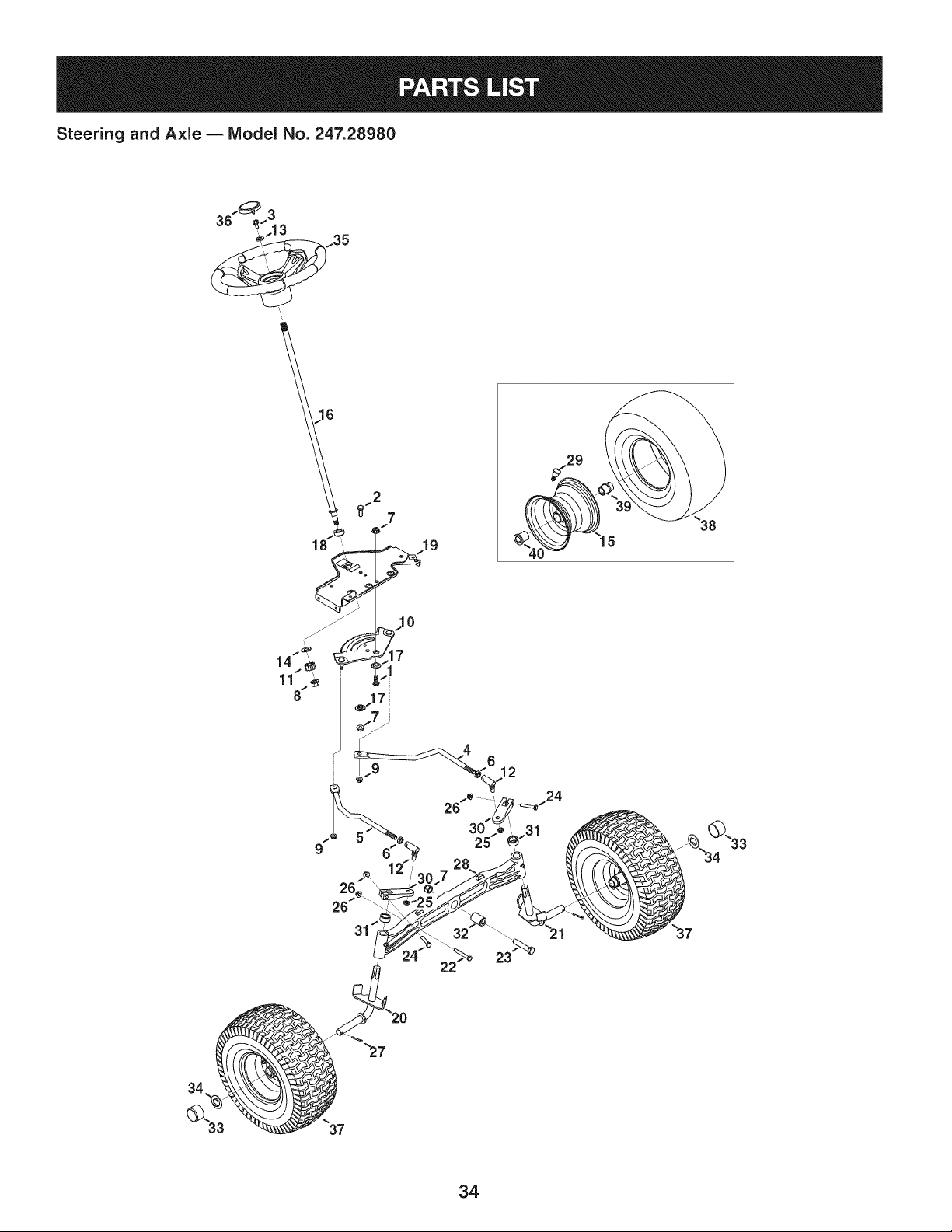
Steering and Axle -- IViodel No. 247.28980
2
7
19
34

Steering and Axle B IViodel No. 247.28980
710-04095 HexHeadScrew,3/8-16:1.00 638-04027-0637 LHAxle Assembly
2 710-0514 HexHeadScrew,3/8-16:1.00 22 710-0395 HexHeadScrew,5/16-18:2.25
3 710-0643 HexHeadScrew,5/16-18:1.00 23 710-0859 HexHeadScrew,3/8-16:2.50
4 711-04998 iLH DragLink i24 710-3180 HexHeadScrew,5/16-18:1.75
5 711-04999 iRH DragLink 25 i912-0214 HexlockNut,3/8-24
6 912-0240 iJamNut,7/16-20 26 712-04063 FlangeiockNut,5/16-18
7 712-04065 iFlangelockNut,3/8-16 27 714-0162 CotterPin,5/32:1.25
8 712-0459 iFlangelockNut,7/16-20 28 719-04413A PivotBarAxle
9 712-3004A iFlangelockNut,5/16-18 29 934-0255 TubelessAirValve
10 717-1550F iSteeringGear 30 748-04065-0637 SteeringBlock
11 717-1554 iSteeringPinionGear 31 748-04068 Spacer,.71IDX .125OD X .56LG
12 923-0448A iBallJoint,7/16-20 32 750-05280 Spacer,.385X 1.00X 1.5075
13 936-3004 FlatWasher,.406X .875X .105 33 731-05674 BumperCap
14 736-3084 FlatWasher,.51X 1.12X .06:HT 34 736-04228A FlatWasher,.7811Dx 1.5900D
15 634-04405-4042 Rim Assembly 35 631-04415 SteeringWheel
16 738-04263 iSteeringShaft,.625OD X24.25LG 36 731-06825 SteeringWheelCap
17 738-04363 ShoulderSpacer,.385X1.25X.3025 i37 634-04406-0961 WheelAssembly
18 741-04237B iHexFlangeBearing5/8 PM 38 i734-1731-0901 Tire
19 783-06043-0637 ISteeringSupportBracket 39 741-0990B FlangeBearing,.7601D
20 638-04021-0637 RH Axle Assembly 40 741-0516B FlangeBearing,.760x 1.00x 1.20LG
35
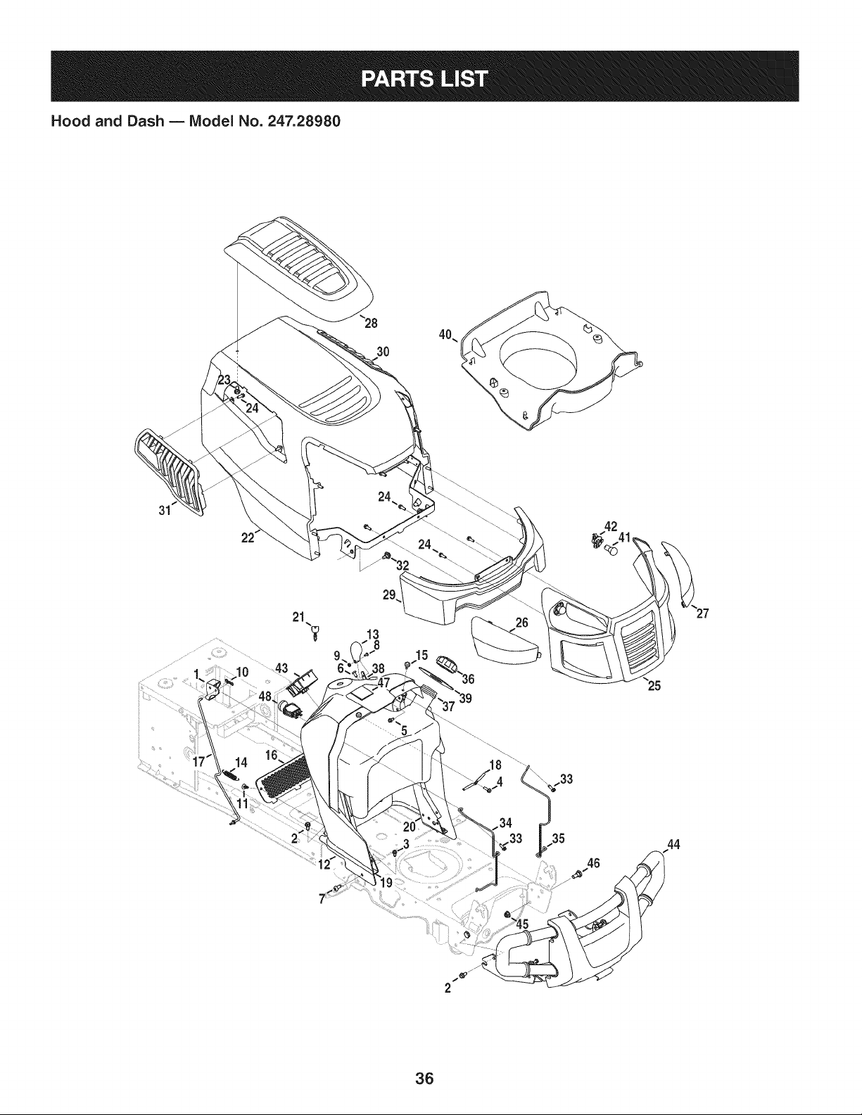
Hood and Dash B IViodel No. 247.28980
31
13
8
15
36

Hood and Dash B Model No. 247.28980
631-04353P DashLever 931-07457 Grill
2 710-04484 TaptiteScrew,LockWasher,5/16-18:.750 i26 731-07458 RHLens
3 710-0599 TaptiteScrew,LockWasher,1/4-20:0.500 i27 731-07459 LHLens
4 710-0895 Hi-LoScrew,LockWasher,1/4-15:0.750 i28 931-07461 HoodScoop
5 710-0896 Screw,LockWasher,1/4-14:0.625 i29 731-07467 LowerGrill
6 710-1017 Screw,1/4-14:0.625 i30 731-07469 LHHoodScoop
7 710-1611B TaptiteScrew,5/16-18:0.750 i31 731-07470 RHHoodScoop
8 710-3217 MachineScrew,#8-32:0.375 i32 738-04091A ShoulderScrew,.43X.29:TT:5/16-18
9 712-0142 HexNut,#8-32:GRA i33 710-0642 TaptiteScrew,1/4-20:0.750
10 714-04040 Bow-tieCotterPin i34 747-05049 RHTankSupportRod
11 726-3046 RatchetClip:.250DIA i35 747-05050 LHTankSupportRod
12 731-07456 Dash i36 751-0603A FuelCap
13 731-07550 ControlKnob i37 951-10573 FuelTank,2.75Gallons
14 732-04580 ExtensionSpring,.500 DIAX 2.733LG i38 946-04556 Throttle/ChokeControl
15 735-0271A Bumper i39 735-04170 FuelTankGasket
16 735-04076 AccessoryNet i40 731-07495 P-StylePlen
17 747-05280 ControlRodLatch i41 925-0963 MiniatureLamp,12V
18 747-1196 LeverRod i42 925-1649 LampSocket
19 783-04285F-0637RHDashSupportPlate i43 725-04992 SwitchKeyModule
20 783-04323F-0637LH DashSupportPlate 44 689-00157 GuardAssembly
21 625-04124 Keys(Setof 2) i45 712-04065 FlangelockNut,3/8-16
22 683-04618-0691 HoodAssembly i46 738-0143 ShoulderBolt,.496x .336:3/8-16
23 710-04187 Hi-loScrew,LockWasher,1/4-15:0.50 i47 925-04036C Hour Meter
24 710-05108 Screw,LockWasher,1/4 DIA:.750 i48 725-04258 PTOSwitch
37
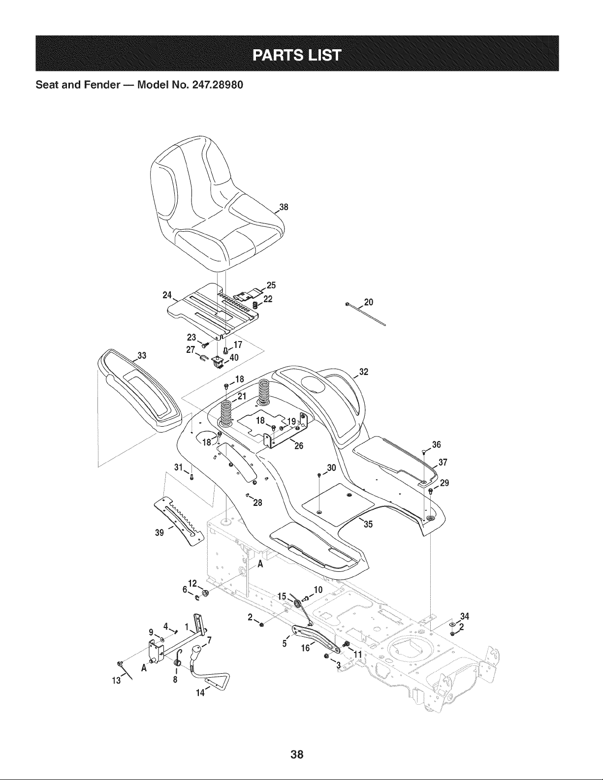
Seat and Fender B Model No. 247.28980
38
24
23
33 27
32
31 30
612_
I0
29
34
38

Seat and Fender B Model No. 247.28980
683-04223-0637 LiftShaftAssembly 732-04561 CompressionSpring, 1.71X 3.735X .238
2 712-04063 FlangelockNut,5/16-18 i22 732-04563 CompressionSpring,.68X 1.065X .055
3 712-04065 FlangelockNut,3/8-16 i23 938-0296 ShoulderScrew,.437X .268:5/16-18
4 914-0104 CotterPin,.072DIA.X 1.13LG i24 783-06049-0691 Seat MountingBracket
5 714-04040 Bow-TieCotterPin i25 783-06050 SeatAdjustmentLever
6 716-0106A E-Ring,.625DIA.SHAFT i26 783-06088-0691 Seat PivotBracket
7 720-04150 HandleGrip i27 783-06448 SwitchRetainerClip
8 732-0874 TorsionSpring i28 710-04187 Hi-LoScrew,LockWasher,1/4-15:0.50
9 736-0105 SpringWasher,.401X .870X .063 i29 710-0451 CarriageBolt,5/16-18:.750
10 738-0138A ShoulderScrew, .437X.470:5/16-18 i30 710-0599 TaptiteScrew,LockWasher,1/4-20:0.500
11 738-04130 ShoulderBolt, .625X.175:3/8-16 i31 710-0895 Hi-LoScrew,LockWasher,1/4-15:0.750
12 941-0225 HexFlangeBearing i32 731-05837 LH FenderCover
13 746-0968 LiftCable, 16.16LG i33 731-06754 RH FenderCover
14 747-04962A Lift Handle i34 736-3078 FlatWasher,.344X 1.00X .063HDN
15 756-04331 PulleyRollerCable i35 783-06118-0691 Fender
16 783-04494C-0637RH LiftArm i36 726-3046 RatchetClip
-- 783-04711C-0637LH LiftArm i37 735-04137 LH FootPad
17 710-04482 Hex HeadFlange,3/8-16:.875 -- 735-04139 RHFootPad
18 710-04484 TaptiteScrew,LockWasher,5/16-18:.750 i38 757-04127 Seat
19 i712-3004A FlangelockNut,5/16-18 i39 783-06181-0637 LiftBracket
20 725-0157 CableTie,3/16X .05X 7.4 i40 925-05013 Seat Switch
3g
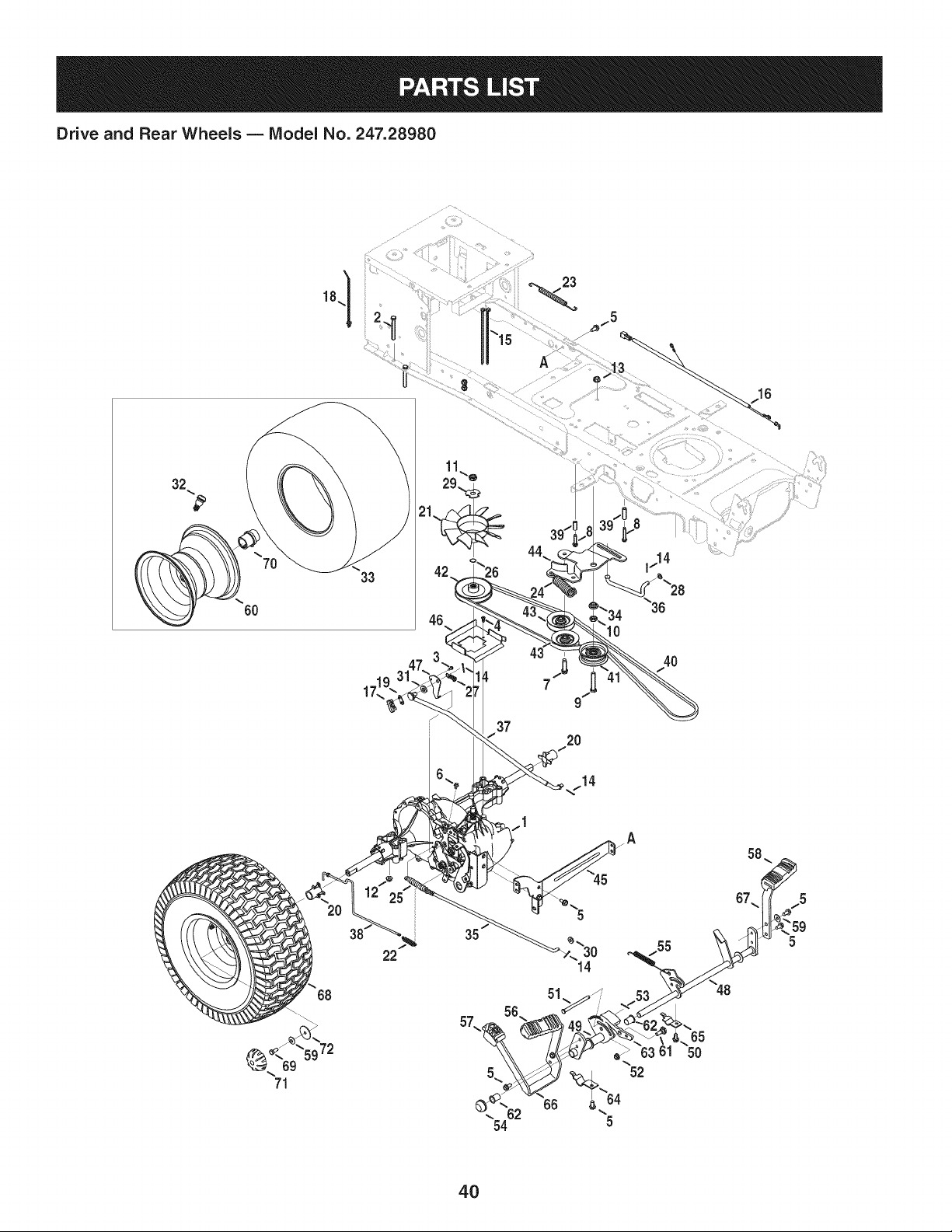
Drive and Rear Wheels B IViodel No. 247.28980
23
32
6O
33
2O
10
4O
16
22
4O

Drive and Rear Wheels B Model No. 247.28980
918-0319 HydroTransmission 747-04979 HydroControlRod
2 710-0176 HexHeadScrew,5/16-18:2.75 i38 747-04991 HydroBypassRod
3 710-0227 iScrew,indentedWasher,#8-18:0.500 i39 750-04456 Spacer,260X .372X 1.420LG
4 710-0351 iScrew,#10-16:0.500 i40 954-04207 V-Belt,4LX 78.9POLY
5 710-04484 TaptiteScrew,indentedWasher,5/16-18:.750 i41 756-04224 FiatIdlerPulley,2.75OD
6 710-0653 TaptiteScrew,indentedWasher,1/4-20:0.375 i42 756-04308 inputPulley,4.13DIA
7 710-1007 TaptiteSeresScrew,:3/8-16:1.500 i43 756-04325 V IdlerPulley,X 3.06
8 710-1325 TaptiteScrew,indentedWasher,1/4-20:1.625 i44 783-06027A CenterIdlerBracket
9 710-3011 HexHeadScrew,3/8-16:2.25 i45 783-06133-0637 HydroMountingBracket
10 912-0240 iJam Nut,7/16-20 i46 783-06260-0637 BeltDisengageSupportBracket
11 912-0346 JamlockNut, 1/2-20 i47 783-1019B SwitchActuatorBracket
12 712-04063 iFlangelockNut,5/16-18 i48 647-04152A BrakeControlAssembly
13 912-0431 iFlangelockNut,3/8-16 i49 683-04488 HydroPedalBracketAssembly
14 914-0111 iCotterPin,3/32:1.0 i50 710-0604A TaptiteScrew,indentedWasher,5/16-18:0.625
15 725-0157 CableTie.3/16X .05X 7.4 i51 711-05068 ClevisPin,5/16 X3.985
16 725-04791A iJumperHarness i52 712-04065 FlangelockNut,3/8-16
17 725-1644 iShortSpringSwitch i53 714-04040 Bow-TieCotterPin
18 926-0154 PushMountCableTie 7.5LG i54 726-0214 PushCap
19 926-0320 InsulatorNutPlate i55 732-04587 ExtensionSpring,.63 DIAX 4.95 LG
20 731-05299A iSleeve,.765IDX 1.500LG 56 735-04118A ForwardPedalPad
21 731-06098 HydroFan i57 735-04135 ReversePedalPad
22 932-0209 ExtensionSpring,.48ODX2.03 i58 735-04136 BrakePedalPad
23 732-04606 ExtensionSpring,.500DIAX 12.6LG i59 736-0242 BellWasher,.340X .872X .060
24 732-04624 ExtensionSpring,1.00DIAX 4.75 i60 634-04369-4042 RimAssembly
25 732-0716D ExtensionSpring,.59ODX 4.00 LG i61 938-0380 ShoulderBolt,.500X .270:3/8-16
26 732-0729 iWireRing i62 741-0495 FlangeBearing,.630 IDX.695OD X .60
27 732-3118 ExtensionSpring,.375ODX 1.44LG 63 748-04203 CruiseLatch
28 936-0264 FiatWasher,.330X .630X .0635 i64 783-05914 PedalSupportBracket
29 736-04263 LockWasher i65 783-05940 PedalSupportBracket,5/8
30 936-3008 FlatWasher,.344X .750X .120 i66 783-06059-0637 DrivePedalBracket
31 736-3010 FiatWasher,.407X .812X .135 i67 783-06103A-0637BrakePedalBracket
32 934-0255 TubelessAirValve 68 634-0104-0961 WheelAssembly
33 734-1730-0901 Tire i69 710-0627 HexHeadScrew,5/16-24:.750
34 738-04420 ShoulderSpacer,1.375X.380X.183 i70 750-0204 Axle Hub
35 747-04139 BrakeRod i71 731-2290A HubCap
36 747-04957A iFootpedalBypassTransmissionRod i72 736-0430 FiatWasher,.350x 1.59x .062
41
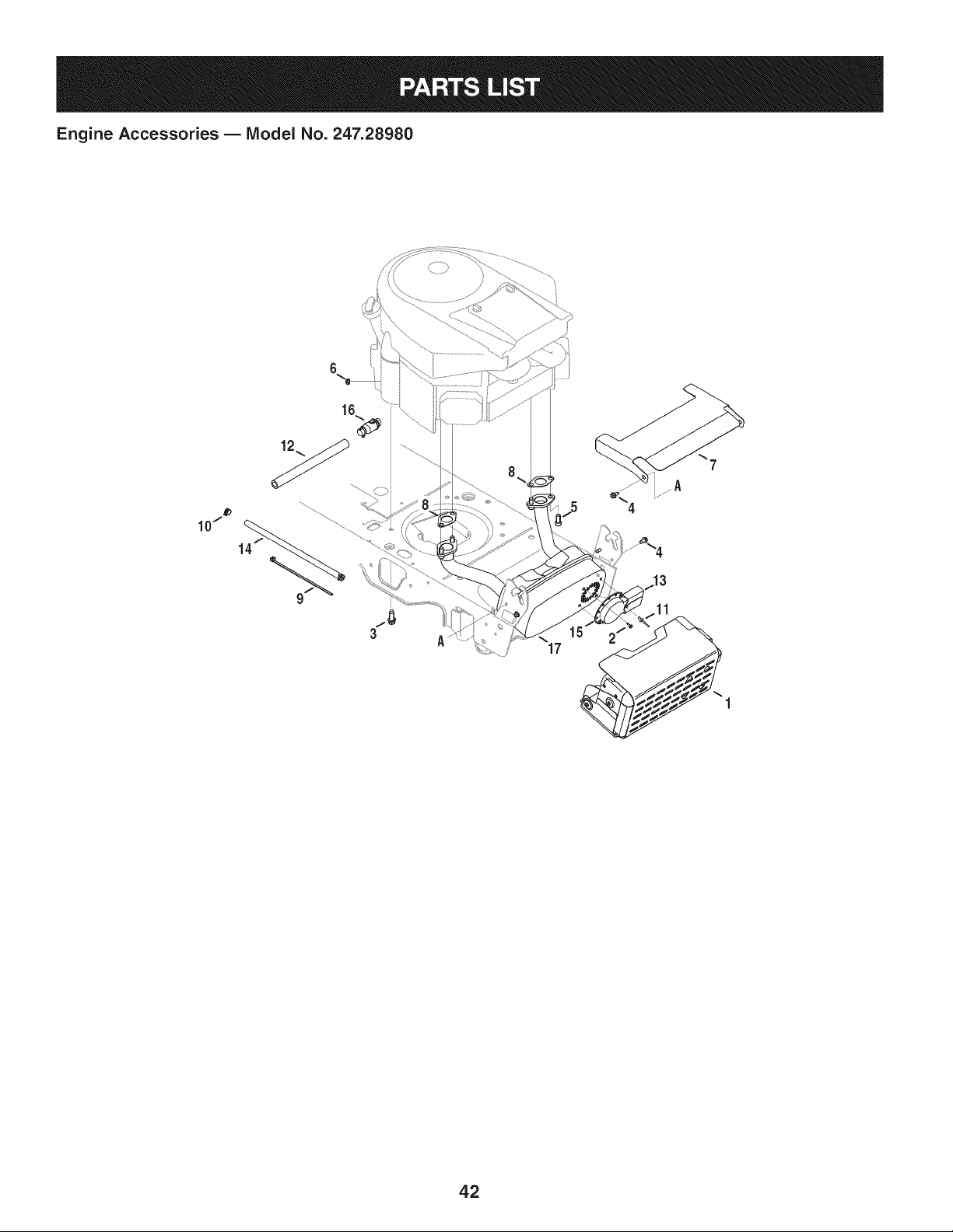
Engine Accessories B IViodel No. 247.28980
16
3
17
42

Engine Accessories B IViodel No. 247.28980
683-04549-0637 MulfflerShieldAssembly
2 710-0227 Screw,IndentedWasher,#8-18:0.500
3 710-04683 TaptiteScrew,IndentedWasher,3/8-16:1.000
4 710-0599 TaptiteScrew,IndentedWasher,1/4-20:0.500
5 710-1314A SocketHeadScrew,5/16-18:.750
6 712-0271 SeresNut, 1/4-20
7 783-06378A HeatShield
8 721-0460 ExhaustGasket
9 725-0157 CableTie,3/16 X .05X 7.4
10 726-0205 HoseClamp,.490DIA.
11 728-04000 Rivet,.188DIAX .300 L
12 751-3141-14 Oil DrainExtensionHose
13 751-0564B MufflerDeflector
14 751-10349 FuelHose
15 751-10353 LongMufflerDeflector
16 951-10517A OilDrain
17 751-10542A MufflerDeflector
43
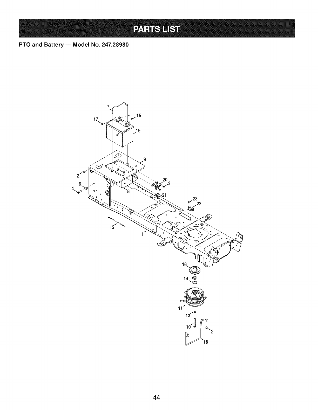
PTO and Battery B IViodel No. 247.28980
7
17
12
15
20
f3
22
44

PTO and Battery B IViodel No. 247.28980
683-04469A-0691Frame
2 710-04484 TaptiteScrew,indentedWasher,5/16-18:.750
3 710-0599 TaptiteScrew,indentedWasher,1/4-20:0.500
4 710-3005 HexHeadScrew,3/8-16:1.25
5 712-04065 FlangelockNut,3/8-16
6 738-04058 ShoulderSpacer,.38X 1.0X .70
7 747-04121A BatteryHolderRod
8 783-0349-0637 BatteryTray
9 783-06089-0637 SeatFrameBracket
10 710-04379A HexHeadScrew,7/16-20:3.50
11 917-04163A ElectricPTOClutch
12 725-0157 CableTie,3/16x .05 x 7.4
13 936-0171 LockWasher,7/16
14 736-0277 FiatWasher,1.031x 1.620x .095
15 712-0271 SeresNut, 1/4-20
16 756-0978B ElectricPTOEnginePulley
17 710-04666 Hex HeadFlange,1/4-20:.75
18 747-05171 BeltGuard
19 725-05088 Battery
20 725-04439 Solenoid,12V
21 712-04064 FlangelockNut, 1/4-20
22 725-04363 InterlockSwitch
23 738-04237A ShoulderScrew,#10-32:.500
45
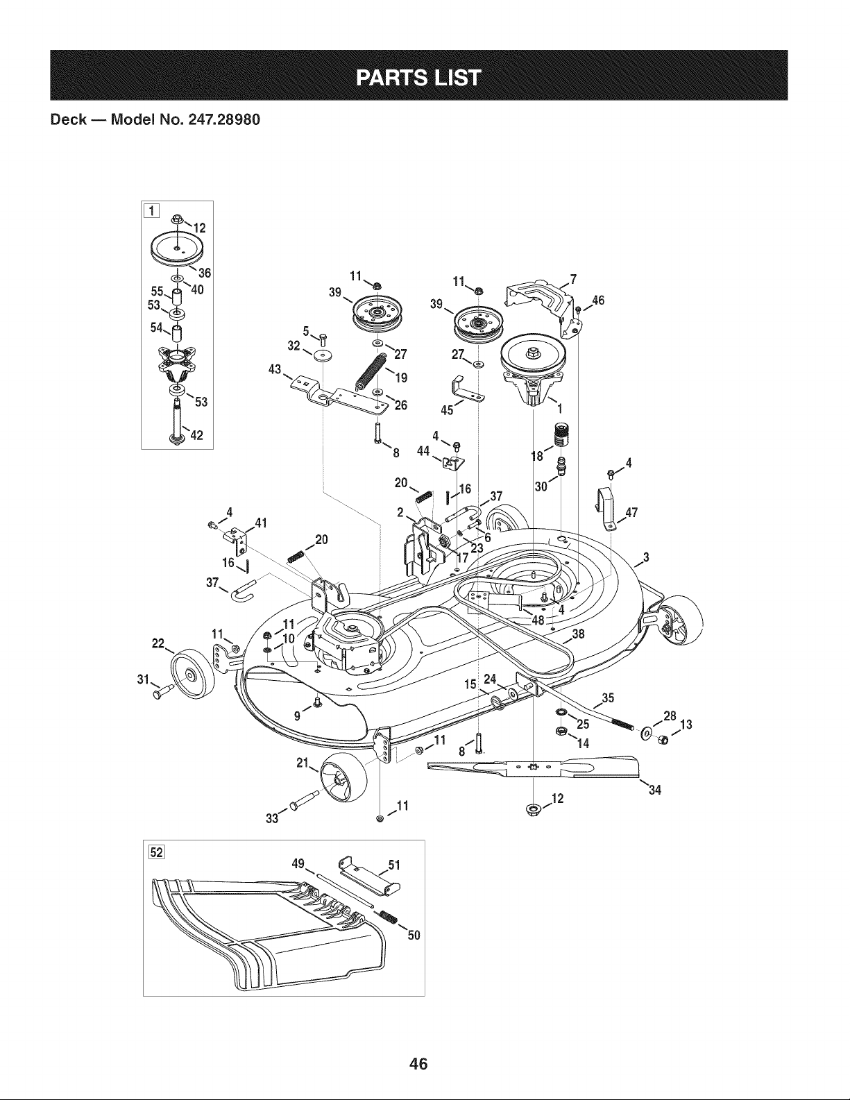
Deck B Model No. 247.28980
8 44
31\
/2813
\34
46

Deck B IViodel No. 247.28980
618-04950 SpindleAssembly
2 683-0254B-4028 DeckHangerBracketAssembly
3 683-04598-0428 DeckAssembly
4 710-04484 TaptiteScrew,indentedWasher,5/16-18:.750
5 710-0514 HexHeadScrew,3/8-16:1.00
6 710-0528 HexHeadScrew,5/16-18:1.25
7 710-0599 TaptiteScrew,indentedWasher,1/4-20:0.500
8 710-3144 HexHeadScrew,3/8-16:2.00
9 710-3178 CarriageBolt,3/8-16:0.75
10 712-0229 PushNut,3/8
11 712-04065 FlangelockNut,3/8-16
12 712-0417A FlangeNut,5/8-18
13 712-04243 Lock Nut, 1/2-13
14 912-0641 HexNut,M16-1.5DIN936
15 753-04070 LynchPin,.1875
16 914-0470 CotterPin, 1/8X 1.25
17 917-04074 DeckGear
18 921-04041 WaterNozzleAdaptor
19 732-0459C ExtensionSpring,.94DIA.X 6.74LG
20 732-04652 CompressionSpring,.535ODX 1.751LG
21 734-04155 Front DeckWheel
22 734-0973 RearDeckWheel
23 936-0119 LockWasher,5/16
24 936-0179 FiatWasher,.531X 1.25X .100
25 736-0225 LockWasher,5/8
26 736-0258 FlatWasher,.385X 1.0X .135
27 736-0262 FiatWasher,.385X .870X .092
28 736-0317 BellWasher,.63X 1.25X .18
936-0344 FiatWasher,.385X 1.0X .030
i30 737-04003D WaterNozzle
i31 938-0373 ShoulderBolt,.496X 1.525:3/8-16
i32 738-04162A ShoulderSpacer,.8840X .190
i33 938-3056 ShoulderBolt, .496X 2.50:3/8-16
i34 942-04308 2-in-1CuttingBlade
i35 747-04944B DeckLiftRod
i36 956-1227 DeckPulley,6.3 DIA
i37 747-1116 DeckReleaseHandleRod
i38 954-04060B V-Belt
i39 756-04129B IdlerPulley,4.25"DIA
i40 936-0351 FlatWasher,.760IDX1.50OD
i41 783-04740-0637 DeckEngageCableBracket
i42 738-1186A SpindleShaft,6.05 LG.
i43 783-05946 IdlerBracket
i44 783-06243-0637 DeckEngageCableBracket
i45 783-06368-0637 4.25 PulleyBeltGuardBracket
i46 783-06424A-4028BeltCover
j47 783-06632-4028 DeckStop
i48 783-06643-4028 DeckIdlerSupportBracket
i49 711-04847A HingePin
i50 732-04372 TorsionSpring
51 783-06074A ChuteBracket
i52 631-04460 Chute Deflector
i53 941-0919 BallBearing,.7871DX 1.850DX.551
i54 750-04936 Spacer,.792X 1.060X 1.860LG
i55 750-0952 Spacer,.792X 1.060X 1.800LG
4.7
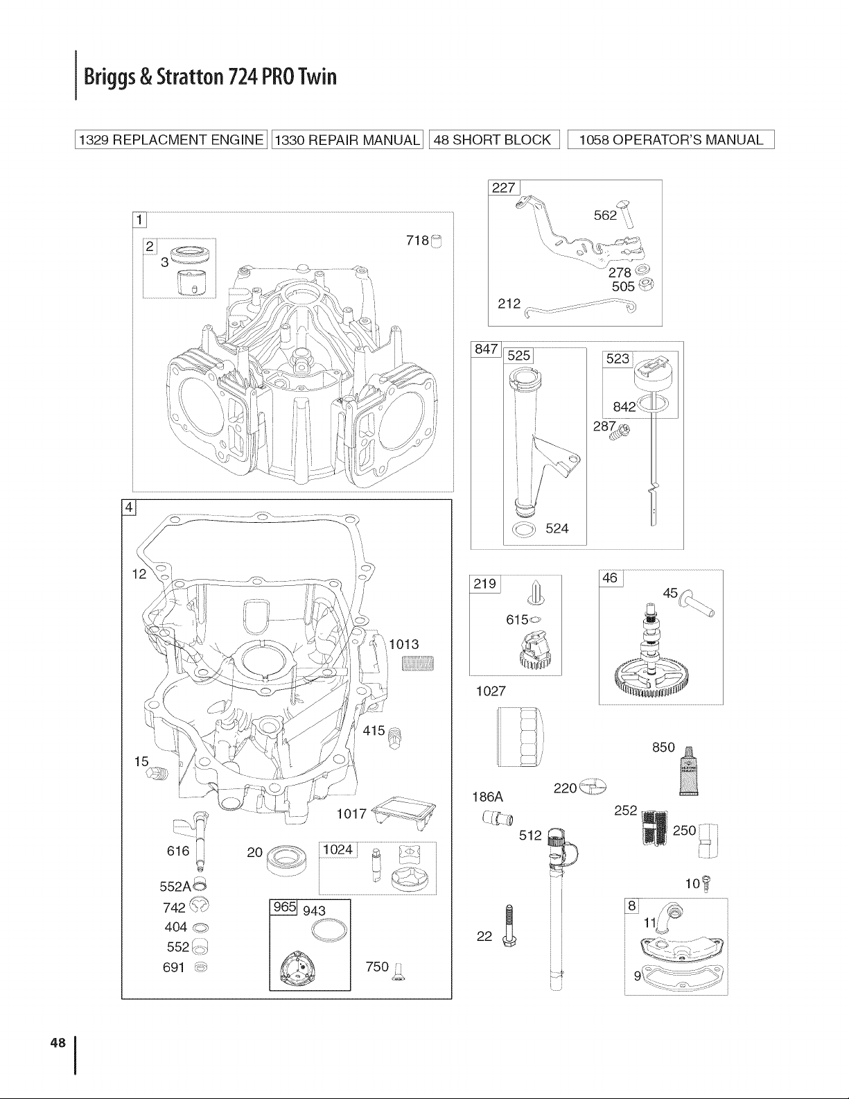
Briggs& Stratton 724PROTwin
11329 REPLACMENT ENGINE] 11330 REPAIR MANUALI148SHORT BLOCK II lO58 OPERATOR'S MANUAL I
//
1013
15
ii
616ii 20
552A_
742 '_,J,-'
404 _->
552 _4:>_
691 _:,J....
1017
750 _,
562
278 :
5o5,_
_:::2_ 524
1027
46
45
85O
186A
512
[
252
250
I i
2
lO_

Briggs& Stratton724PROTwin
_25i
385d_
51A
....
654 _i:!_3
53;_
_' 24 _
240 ., ........"
/
415_
...................................................
108F--_j_ '
51A
1169
15o_
\ ...........................................J
..................
;;no7 _" f:":_
.............................._ _ iI /
....................:::::_.__ i .............2Z_ ............
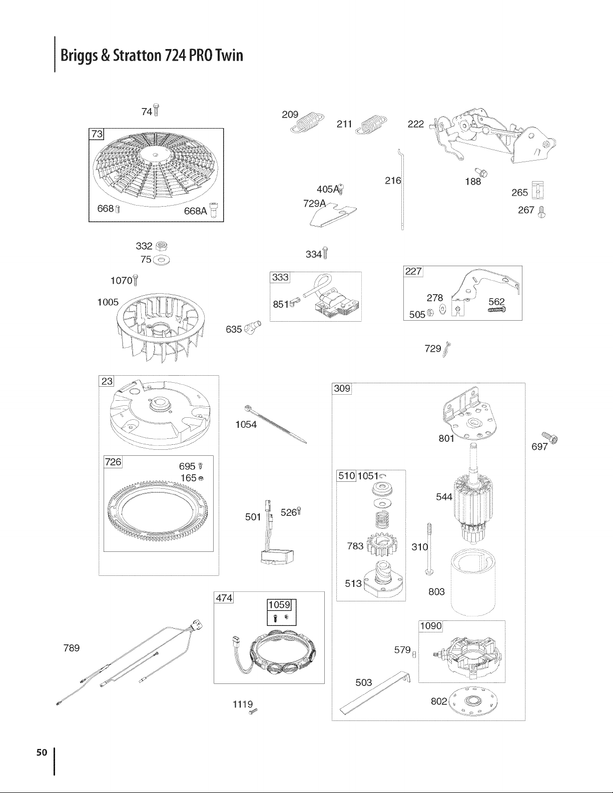
Briggs& Stratton 724PROTwin
74_
211 J;_y-
222
1070_
ioo5j
4o5_._
72_A_ _ z_
334'i_'
3331
216
H
H
H
H
H
H
188 _:,
265 ==:_
267
789
i.t:i_5262
5Ol:,
",!
1119
309
544
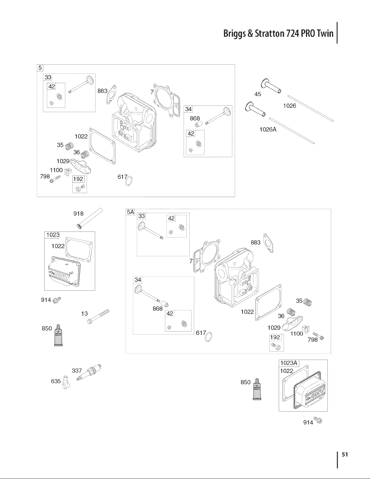
Briggs& Stratton 724PROTwin
34:_ _,_
,868
42:
[
[
[
1026 _
1026A ":_
914 ,_1_
85O
883
7
!42!
1O22
@ 1029
,617,/_
, 798
635
85O
914 ;_
51
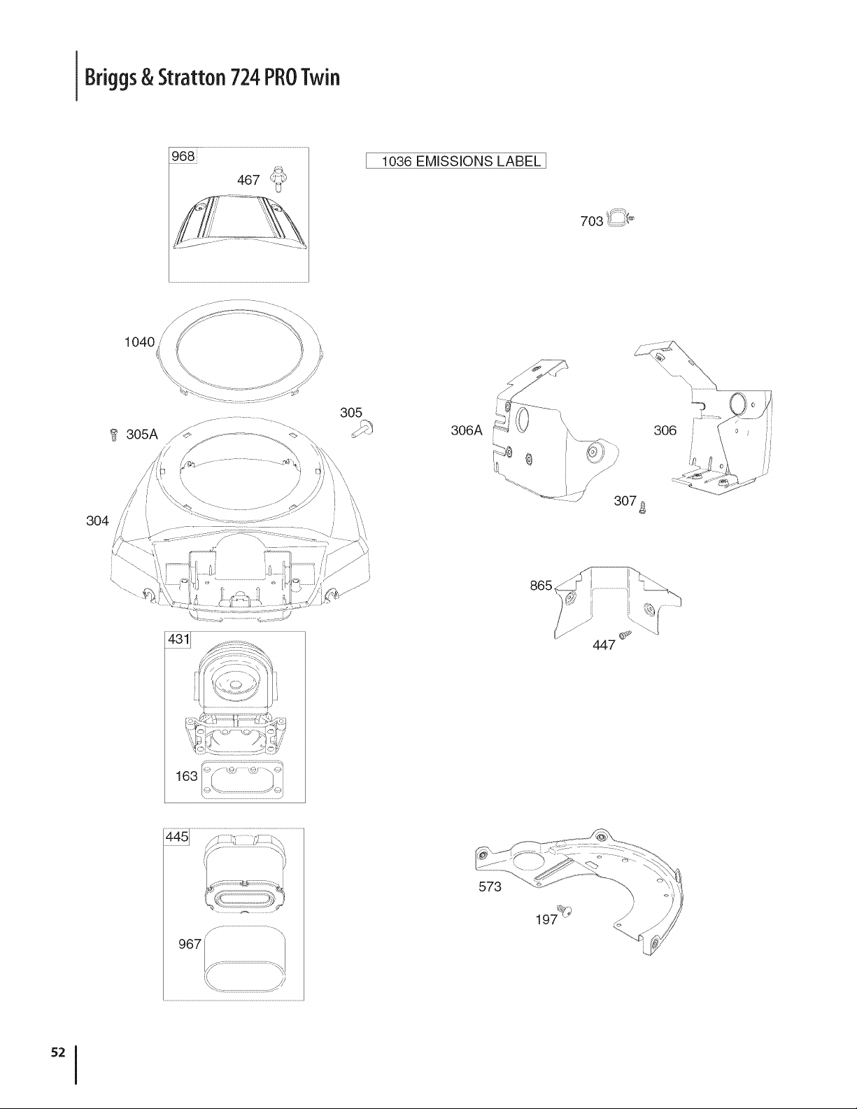
Briggs& Stratton 724PROTwin
968[
467 _}_
1036 EMISSIONS LABEL[
1O4O
305
i
306A
307_
f
\
163
865
447
573
197%
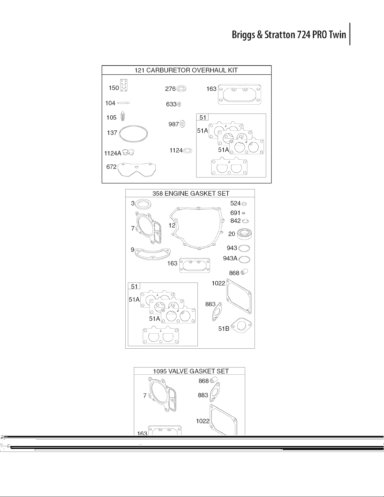
Briggs& Stratton 724PROTwin
150 i_3
104 .............
1124A _
121 CARBURETOR OVERHAUL KIT
:::::::::::::::::::::::::::::::::::: :::::::::::::: _
163 ,._/ \\is '.... \-_
633 _ "
1124,,
51
1095 VALVE GASKET SET
883
1022

Briggs& Stratton 724PROTwin
D _ O O
BS-793564 CylinderAssembly
2 BS-499585 Kit-Bushing/Seal(MagnetoSide)
3+ BS-391086s Seal-Oil(MagnetoSide)
4 BS-796307 Sump-Engine
5 BS-796231 Head-Cylinder(Cylinder#1)
5A BS-796232 Head-Cylinder(Cylinder#2)
7+& BS-693997 Gasket-CylinderHead
8 BS-792185 BreatherAssembly
9+ BS-690937 Gasket-Breather
10 BS-697551 Screw(BreatherAssembly)
11 BS-792184 Tube-Breather
12+ BS-697227 Gasket-Crankcase
13 BS-793988 Screw(CylinderHead)
15 BS-690946 Plug-OilDrain
16 BS-796540 Crankshaft
20+ BS-795387 Seal-Oil(PTOSide)
22 BS-694966 Screw(CrankcaseCover/Sump)
23 BS-691053 Flywheel
24 BS-222698s Key-Flywheel
25 BS-792023 PistonAssembly(Standard)
25 BS-792072 PistonAssembly(.020"Oversize)
26 BS-793561 RingSet (Standard)
26 BS-792073 RingSet (.020"Oversize)
27 BS-690975 Lock-PistonPin
28 BS-696581 Pin-Piston
29 BS-796209 Rod-Connecting
32 BS-690976 Screw(ConnectingRod)
33 BS-697576 Valve-Exhaust
34 BS-792200 Valve-Intake
35 BS-694865 Spring-Valve(Intake)
36 BS-694865 Spring-Valve(Exhaust)
42 BS-499586 Keeper-Valve
45 BS-690977 Tappet-Valve
46 BS-797242 Gear-Cam
48 BS-797093 ShortBlock
50 BS-695241 Manifold-Intake
51+ BS-795123 Gasket-intake
51A BS-690950 Gasket-intake
51B BS-690949 Gasket-intake
D _ O O
BS-690951 Stud(Carburetor)
54 BS-699816 Screw(IntakeManifold)
73 BS-494439 Screen-Rotating
74 BS-698425 Screw(RotatingScreen)
75 BS-691056 Washer(Flywheel)
95 BS-690718 Screw(ThrottleValve)
98 BS-699721 Kit-IdleSpeed
104% BS-694918 Pin-FloatHinge
105 BS-698537 Valve-FloatNeedle
108 BS-699723 Valve-Choke
117 BS-842630 Jet-Main(Standard)
118 BS-797477 Jet-Main(HighAltitude)
121 BS-792455 Kit-CarburetorOverhaul
125 BS-796997 Carburetor
130 BS-690993 Valve-Throttle
131 BS-499805 Kit-ThrottleShaft
133 BS-699724 Float-Carburetor
135 BS-699729 Tube-FuelTransfer
137% BS-690994 Gasket-FloatBowl
141 BS-796228 Kit-ChokeShaft
142 BS-699726 Nozzle-Carburetor
146 BS-690979 Key-Timing
150 BS-690995 Gasket-Nozzle
163+% BS-691001 Gasket-AirCleaner
165 BS-693148 Nut (Ring Gear)
186 BS-795985 Connector-Hose
187 BS-791766 Line-Fuel(Cutto RequiredLength)
188 BS-697551 Screw(Control Bracket)
192 BS-690083 Adjuster-RockerArm
197 BS-697820 Screw(Back Plate)
209 BS-796658 Spring-Governor(Yellow/Brown)
211 BS-796225 Spring-GovernedIdle(Orange)
212 BS-695238 Link-Throttle
216 BS-796229 Link-Choke
217 BS-695409 Spring-ChokeReturn
219 BS-793338 Gear-Governor
+-- Includedin EngineGasketSet,Key.No.358
&-- IncludedinValveGasketSet,KeyNo. 1095
%-- IncludedinCarburetorOverhaulKit,KeyNo.121

Briggs& Stratton 724PROTwin
D _ O O
BS-690412 Washer(GovernorGear)
221 BS-841026 Cup-Governor
222 BS-796226 Bracket-Control
227 BS-796223 Lever-GovernorControl
231 BS-690718 Screw(ChokeValve)
239 BS-792028 Switch-OilPressure
240 BS-695666 Filter-Fuel
250 BS-690957 Retainer-Breather
252 BS-794389 Collector-Oil
265 BS-691024 Clamp-Casing
267 BS-695134 Screw(CasingClamp)
276% BS-695410 Washer-Sealing
278 BS-792651 Washer(GovernorControl Lever)
287 BS-697551 Screw(DipstickTube)
304 BS-797407 Housing-Blower
305 BS-691005 Screw(BlowerHousing)
Screw(BlowerHousingto Intake
305A BS-790690
Elbow)
306 BS-796541 Shield-Cylinder(Cylinder#2)
306A BS-796852 Shield-Cylinder(Cylinder#1)
307 BS-697551 Screw(CylinderShield)
309 BS-497595 Motor-Starter
310 BS-690323 Screw(StarterMotor)
332 BS-691059 Nut(Flywheel)
333 BS-691060 Armature-Magneto
334 BS-691061 Screw(MagnetoArmature)
337 BS-491055s Plug-Spark
358 BS-694012 GasketSet-Engine
385 BS-797409 Screw(FuelPump)
387 BS-808656 Pump-Fuel
404 BS-690442 Washer(GovernorCrank)
415 BS-794903 Plug(OilPressureSwitchHole)
418 BS-795912 Plate-Carburetor
431 BS-792297 Elbow-Intake
445 BS-792105 Filter-AirCleanerCartridge
447 BS-691003 Screw(AirGuideCover)
467 BS-790697 Knob-AirCleaner
474 BS-696457 Alternator
501 BS-794360 Regulator
5O5
510
513
523
524+
m _ O O
BS-691532 Strap-Starter
BS-691029 Nut(GovernorControlLever)
BS-696541 Drive-Starter
BS-692024 Clutch-Drive
BS-691036 Dipstick
BS-691032 Seal-DipstickTube
525 BS-691037 Tube-Dipstick
526 BS-691129 Screw(Regulator)
Armature-Starter(ServicewithStarter
544
Motor497595,Reference309)
552 BS-796638 Bushing-GovernorCrank
552A BS-690553 Bushing-GovernorCrank
562 BS-690311 Screw(GovernorControlLever)
573 BS-790444 Plate-Back
579 BS-691029 Nut(StarterCable)
601 BS-691038 Clamp-Hose(Black)
615 BS-698290 Retainer-GovernorShaft
616 BS-691045 Crank-Governor
617 BS-697891 SeaI-ORing(IntakeManifold)(Red)
633% BS-699813 Seal-Choke/ThrottleShaft
634 BS-698779 Spring/SealAssembly
635 BS-66538s Boot-SparkPlug
654 BS-690958 Nut(Carburetor)
668+ BS-691215 Spacer(RotatingScreen)
668A BS-691500 Spacer(RotatingScreen)
672 BS-690234 Gasket-CarburetorPlate
691+ BS-790574 Seal-GovernorShaft
695 BS-693149 Screw(Ring Gear)
697 BS-690372 Screw(DriveCap)
703 BS-691010 Clip
718 BS-690959 Pin-Locating
726 BS-499612 Gear-Ring
729 BS-797454 Clip-Wire
741 BS-690980 Gear-Timing
742 BS-690328 Retainer-ERing(GovernorCrank)
750 BS-796208 Screw(OilPumpCover)
+ -- Includedin EngineGasketSet,Key.No.358
& --Included in ValveGasketSet,KeyNo.1095
% -- Includedin CarburetorOverhaulKit, KeyNo. 121
55

Briggs& Stratton 724PROTwin
D _ O O
BS-695708 Gear-Pinion
789 BS-797460 Harness-Wiring
798 BS-697890 Screw(RockerArm)
801 BS-691283 Cap-Drive
802 BS-691286 Cap-End
803 Housing-Starter(ServicewithStarter
Motor497595,Reference309)
842 BS-691031 Seal-ORing(DipstickTube)
847 BS-499602 Dipstick/TubeAssembly
850 BS-100106 Sealant-Liquid
851 BS-493880s Terminal-SparkPlug
865 BS-792286 Cover-AirGuide(Valley)
868+ BS-690968 Seal-Valve
883+& BS-690970 Gasket-Exhaust
914 BS-691127 Screw(RockerCover)
918 BS-797408 Hose-Vacuum
929 BS-695239 Screw(ChokeControlBracket)
943 BS-796222 Seal-ORing(Oil PumpCover)
947 BS-841546 Solenoid-Fuel
965 BS-796221 Cover-OilPump
967 BS-792303 Filter-PreCleaner
968 BS-795120 Cover-AirCleaner
975 BS-793592 Bowl-Float
987 BS-691000 Seal-ThrottleShaft
1005 BS-791236 Fan-Flywheel
1013 BS-690954 Nipple-OilFilter
1017 BS-796214 Screen-OilPump
1022 BS-690971 Gasket-RockerCover
1023 BS-793146 Cover-Rocker(Cylinder#1)
1023A BS-499600 Cover-Rocker(Cylinder#2)
1024 BS-796220 Pump-Oil
1026 BS-690981 Rod-Push(Exhaust)
1026A BS-690982 Rod-Push(Intake)
1027 BS-795890 Filter-Oil
1029 BS-690972 Arm-Rocker
Label-Emissions(Availablefroma
1036
Briggs& StrattonAuthorizedDealer)
1040 BS-791237 Plate-Trim
1051 BS-691265 Ring-Retaining(StarterDrive)
D _ W O
BS-280275 Tie-Cable
1058 BS-277103 Operator'sManual
1059 BS-698516 Kit-Screw/Washer(Alternator)
1070 BS-791680 Screw(FlywheelFan)
1090 BS-691293 Retainer-Brush
1095 BS-694013 GasketSet-Valve
1100 BS-791959 Pivot-RockerArm
1119 BS-691183 Screw(Alternator)
1124 BS-841653 Seal-ORing(FuelTransferTube)
1124A BS-690988 Seal-O Ring(FuelTransferTube)
1126 BS-690991 Screw(FuelTransferTube)
1127 BS-695407 Screw(Fuel Bowl)
1128 BS-690990 Screw(CarburetorNozzle)
1169 BS-690990 Screw(CarburetorPlate)
1330 BS-273521 RepairManual
1329 BS-44Q777-O137-G1 ReplacementEngine
+ --Included in EngineGasketSet,Key.No.358
& -- Includedin ValveGasketSet,KeyNo.1095
% -- Includedin CarburetorOverhaulKit, KeyNo. 121
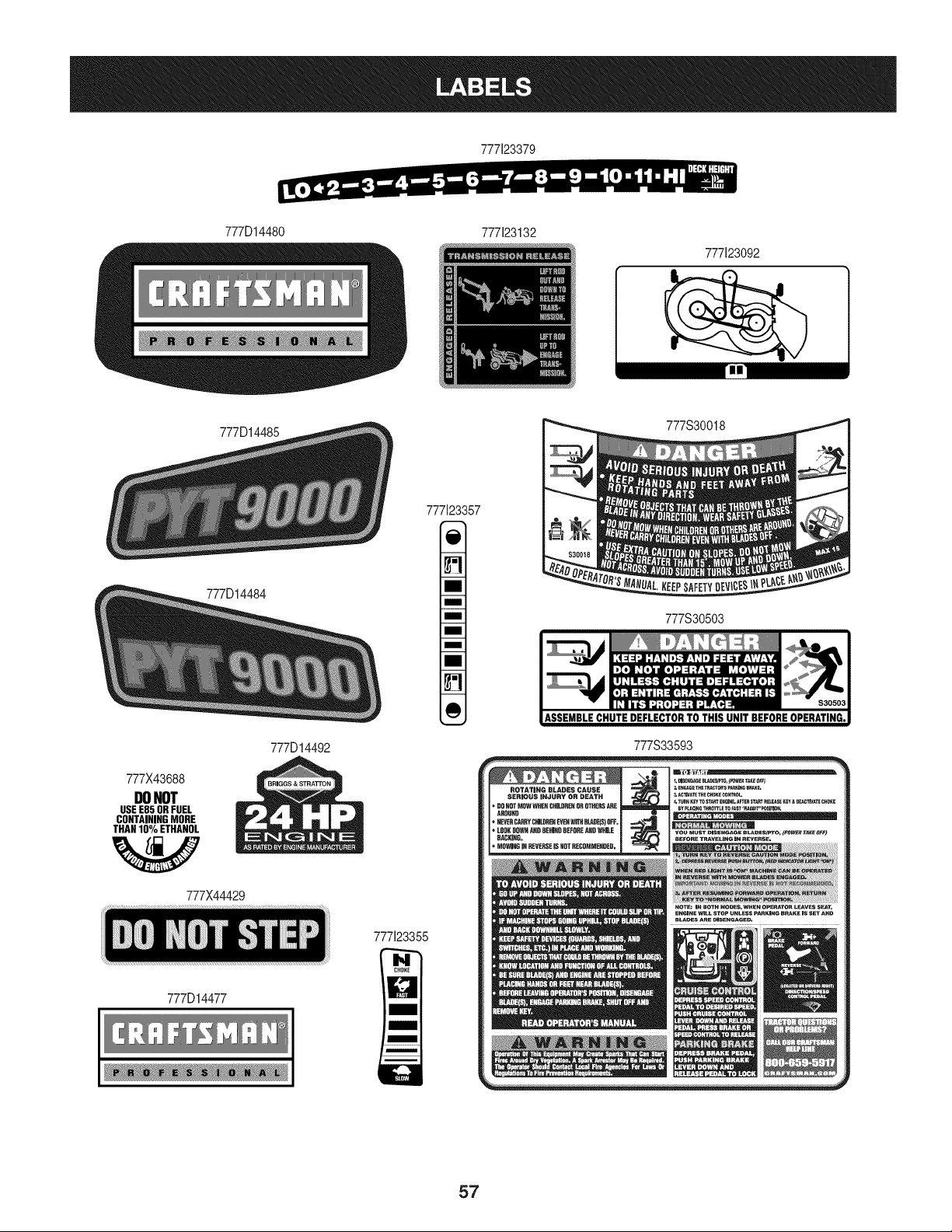
777123379
777D14480 777123132
777123092
777D14485
777D14484
777123357
777S30018
777S30503
777X43688
DONOT
USEE85 ORFUEL
CONTAININGMORE
THAN10% ETHANOL
W
777X44429
777D14492
777D14477
777123355
777S33593
57
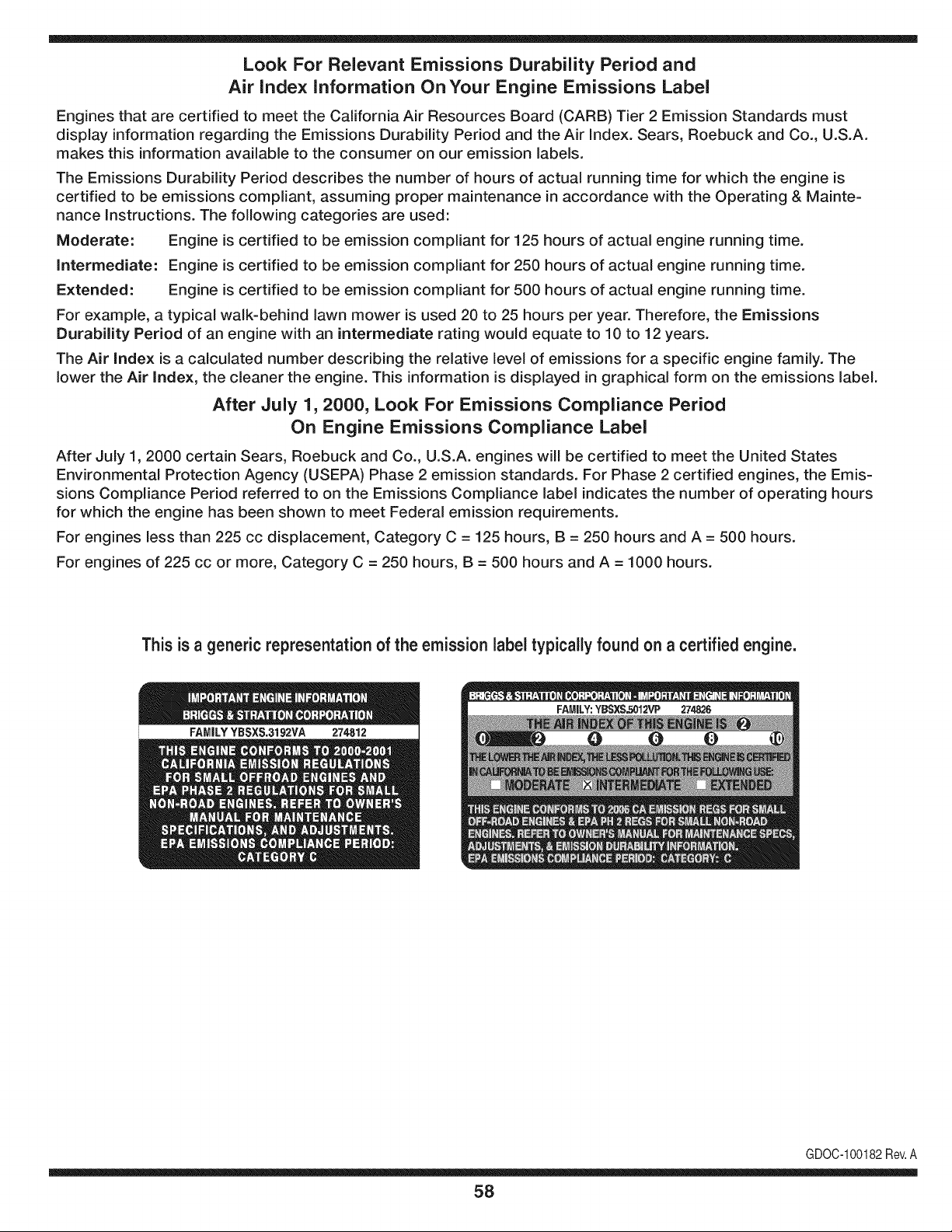
Look For Relevant Emissions Durability Period and
Air index information On Your Engine Emissions Label
Engines that are certified to meet the California Air Resources Board (CARB) Tier 2 Emission Standards must
display information regarding the Emissions Durability Period and the Air Index. Sears, Roebuck and Co., U.S.A.
makes this information available to the consumer on our emission labels.
The Emissions Durability Period describes the number of hours of actual running time for which the engine is
certified to be emissions compliant, assuming proper maintenance in accordance with the Operating & Mainte-
nance Instructions. The following categories are used:
Moderate: Engine is certified to be emission compliant for 125 hours of actual engine running time.
Intermediate: Engine is certified to be emission compliant for 250 hours of actual engine running time.
Extended: Engine is certified to be emission compliant for 500 hours of actual engine running time.
For example, a typical walk-behind lawn mower is used 20 to 25 hours per year. Therefore, the Emissions
Durability Period of an engine with an intermediate rating would equate to 10 to 12 years.
The Air Index is a calculated number describing the relative level of emissions for a specific engine family. The
lower the Air Index, the cleaner the engine. This information is displayed in graphical form on the emissions label.
After July 1,2000, Look For Emissions Compliance Period
On Engine Emissions Compliance Label
After July 1, 2000 certain Sears, Roebuck and Co., U.S.A. engines will be certified to meet the United States
Environmental Protection Agency (USEPA) Phase 2 emission standards. For Phase 2 certified engines, the Emis-
sions Compliance Period referred to on the Emissions Compliance label indicates the number of operating hours
for which the engine has been shown to meet Federal emission requirements.
For engines less than 225 cc displacement, Category C = 125 hours, B = 250 hours and A = 500 hours.
For engines of 225 cc or more, Category C = 250 hours, B = 500 hours and A = 1000 hours.
This is a generic representation of the emission label typically found on a certified engine.
FAMILYYBSXS.3192VA 274812
GDOC-100182Rev.A
58
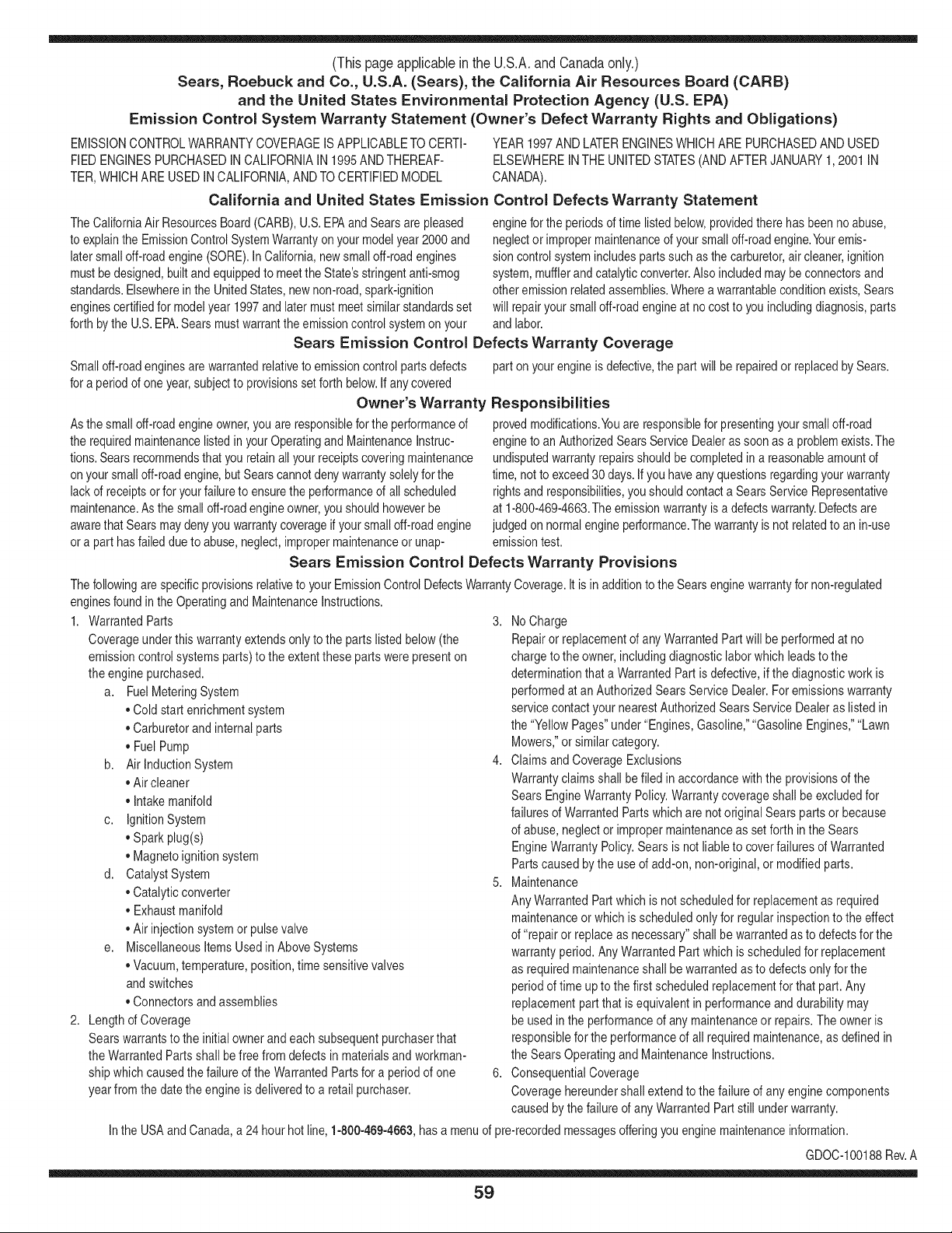
(Thispageapplicableinthe U.S.A.and Canadaonly.)
Sears, Roebuck and Co., U.S.A. (Sears), the California Air Resources Board (CARD)
and the United States Environmental Protection Agency (U.S. EPA)
Emission Control System Warranty Statement (Owner's Defect Warranty Rights and Obligations)
EMISSIONCONTROLWARRANTYCOVERAGEISAPPLICABLETO CERTI-
FIEDENGINESPURCHASEDIN CALIFORNIAIN1995ANDTHEREAF-
TER,WHICHARE USEDINCALIFORNIA,ANDTOCERTIFIEDMODEL
California and United States Emission
The CaliforniaAir ResourcesBoard(CARD),U.S.EPAand Searsare pleased
to explainthe EmissionControlSystemWarrantyon your modelyear2000and
latersmalloff-roadengine(SORE).In California,newsmall off-roadengines
mustbe designed,builtand equippedto meettheState'sstringentanti-smog
standards.Elsewherein theUnitedStates,newnon-road,spark-ignition
enginescertifiedfor modelyear 1997and latermustmeetsimilarstandardsset
forth bythe U.S.EPA.Searsmustwarranttheemissioncontrol systemonyour
YEAR 1997AND LATERENGINESWHICHARE PURCHASEDANDUSED
ELSEWHEREIN THE UNITEDSTATES(ANDAFTERJANUARY1,2001 IN
CANADA).
Control Defects Warranty Statement
enginefor theperiodsoftime listedbelow,providedtherehas been noabuse,
neglector impropermaintenanceof your smalloff-roadengine.Youremis-
sion controlsystemincludespartssuch as thecarburetor,air cleaner,ignition
system,mufflerand catalyticconverter.Also includedmaybe connectorsand
otheremissionrelatedassemblies.Wherea warrantableconditionexists,Sears
will repairyour smalloff-roadengineat no costto you includingdiagnosis,parts
and labor.
Sears Emission Control Defects Warranty Coverage
Smalloff-roadenginesarewarrantedrelativeto emissioncontrol partsdefects
fora periodof one year,subjectto provisionsset forthbelow.Ifany covered
Owner's Warranty
Asthe smalloff-roadengineowner,you are responsiblefor theperformanceof
therequiredmaintenancelistedin yourOperatingand MaintenanceInstruc-
tions.Searsrecommendsthatyou retain all yourreceiptscoveringmaintenance
on yoursmalloff-roadengine,butSears cannotdenywarrantysolelyfor the
lackof receiptsor for yourfailureto ensuretheperformanceof all scheduled
maintenance.As the smalloff-roadengineowner,you shouldhoweverbe
awarethat Searsmay denyyou warrantycoverageif your smalloff-roadengine
ora part hasfaileddueto abuse,neglect,impropermaintenanceor unap-
parton yourengineis defective,the part willbe repairedorreplacedbySears.
Responsibilities
provedmodifications.Youare responsiblefor presentingyour smalloff-road
engineto an AuthorizedSearsServiceDealeras soonas a problemexists.The
undisputedwarrantyrepairsshouldbecompletedina reasonableamountof
time,not to exceed30 days.Ifyou haveanyquestionsregardingyourwarranty
rightsand responsibilities,you shouldcontacta SearsService Representative
at 1-800-469-4663.The emissionwarrantyis a defectswarranty.Defectsare
judgedon normalengineperformance.Thewarrantyis notrelatedto an in-use
emissiontest.
Sears Emission Control Defects Warranty Provisions
ThefollowingarespecificprovisionsrelativetoyourEmissionControlDefectsWarrantyCoverage.It isinadditiontotheSearsenginewarrantyfornon-regulated
enginesfound in the Operatingand MaintenanceInstructions.
1. WarrantedParts
Coverageunderthis warrantyextendsonly to the parts listedbelow (the
emissioncontrolsystemsparts)to the extentthese partswere presenton
the engine purchased.
a. FuelMeteringSystem
• Cold start enrichmentsystem
• Carburetorand internalparts
• FuelPump
b. Air lnduction System
• Air cleaner
• Intakemanifold
c. IgnitionSystem
• Spark plug(s)
• Magnetoignitionsystem
d. CatalystSystem
• Catalyticconverter
• Exhaustmanifold
• Air injectionsystemor pulsevalve
e. MiscellaneousItemsUsedin AboveSystems
• Vacuum,temperature,position,timesensitivevalves
andswitches
• Connectorsandassemblies
2. Lengthof Coverage
Searswarrantsto the initialownerand eachsubsequentpurchaserthat
the WarrantedParts shallbefree fromdefects in materialsandworkman-
shipwhich causedthe failure of the WarrantedPartsfor a periodof one
yearfromthe datethe engineis deliveredto a retailpurchaser.
3. NoCharge
Repairor replacementof anyWarrantedPartwill be performedat no
chargeto the owner,includingdiagnosticlabor whichleadsto the
determinationthata WarrantedPartis defective,ifthe diagnosticwork is
performedat anAuthorizedSearsServiceDealer.Foremissionswarranty
servicecontact yournearestAuthorizedSearsServiceDealeras listed in
the "YellowPages"under"Engines,Gasoline,""GasolineEngines,""Lawn
Mowers,"orsimilarcategory.
4. Claimsand CoverageExclusions
Warrantyclaimsshall be filed in accordancewiththe provisionsof the
Sears EngineWarrantyPolicy.Warrantycoverageshall be excludedfor
failuresof WarrantedPartswhichare not original Sears partsor because
of abuse,neglector impropermaintenanceas setforth inthe Sears
EngineWarrantyPolicy.Sears is notliableto coverfailuresof Warranted
Partscausedby the use of add-on,non-original,or modifiedparts.
5. Maintenance
Any WarrantedPart whichis notscheduledfor replacementas required
maintenanceor whichis scheduledonly for regularinspectionto the effect
of "repairor replaceas necessary"shallbe warrantedasto defectsfor the
warrantyperiod.Any WarrantedPartwhich is scheduledfor replacement
as requiredmaintenanceshallbe warrantedasto defectsonly forthe
periodof time upto the first scheduledreplacementfor that part. Any
replacementpart that is equivalentin performanceand durabilitymay
be usedin the performanceof any maintenanceor repairs.The owneris
responsibleforthe performanceof all requiredmaintenance,as definedin
the SearsOperatingand MaintenanceInstructions.
6. ConsequentialCoverage
Coveragehereundershallextend to the failure of any engine components
caused bythe failureof any WarrantedPartstill underwarranty.
Inthe USAandCanada,a 24 hour hotline, 1-800-469-4663,has a menu of pre-recordedmessagesofferingyou enginemaintenanceinformation.
GDOC-100188Rev.A
59
FEDERAL and/or CALIFORNIA EMISSION CONTROL WARRANTY STATEMENT
YOUR WARRANTY RIGHTS AND OBLIGATIONS
MTDConsumerGroupInc,the UnitedStatesEnvironmentalProtectionAgency (EPA),and, forthose productscertifiedfor sale in the stateof California,the
CaliforniaAir ResourcesBoard(CARB)are pleasedto explainthe emission(evaporativeand/or exhaust)controlsystem(ECS) warrantyon youroutdoor 2006
andlater smalloff-roadspark-ignitedengine andequipment(outdoorequipmentengine)In California,new outdoorequipmentenginesmustbe designed,built and
equippedto meetthe State'sstringentanti-smogstandards(in otherstates, 1997andlater modelyear equipmentmustbe designed,built, and equippedto meet
theU.S. EPAsmalloff-road, sparkignitionengine regulations.MTDConsumerGroupInc mustwarrantthe ECSon your outdoorequipmentenginefor the periodof
timelisted belowprovidedtherehas been no abuse,neglector impropermaintenanceof outdoorequipmentengine.
Your ECSmayincludeparts such as thecarburetor,fuel-injectionsystem,the ignitionsystem,catalyticconverter,fuel tanks,fuel lines,fuelcaps,valves,canisters,
filters,vapor hoses,clamps,connectors,andotherassociatedemission-relatedcomponents.
Wherea warrantableconditionexists, MTDConsumerGroupIncwill repairyouroutdoor equipmentengineat no cost to youincludingdiagnosis,parts and labor.
MAN UFACTURER'S WARRANTY COVERAGE:
Thisemissioncontrolsystemis warrantedfor two years. If any emission-relatedpart on your outdoorequipmentengineis defective,the part will be repairedor
replacedby MTDCONSUMERGROUPINC.
OWNER'S WARRANTY RESPONSIBILITIES:
Asthe outdoorequipmentengineowner,you are responsiblefor performanceof the requiredmaintenancelisted inyour owner'smanual.MTDConsumerGroup
Inc recommendsthat you retain allreceiptscoveringmaintenanceon youroutdoorequipmentengine,butMTDConsumerGroupInc cannotdeny warrantysolely
forthe lackof receipts.
Asthe outdoorequipmentengineowner,you shouldhoweverbe awarethat MTDConsumerGroupInc maydenyyou warrantycoverageif your outdoorequipment
engineor a part has faileddue to abuse,neglect,or impropermaintenanceor unapprovedmodifications.
Youare responsiblefor presentingyouroutdoor equipmentengineto MTDConsumerGroupInc'sdistributioncenteror servicecenteras soon asthe problem
exists.The warrantyrepairsshouldbe completedin a reasonableamountof time, not to exceed30 days. If you havea questionregardingyour warrantycoverage,
you shouldcontactthe MTDConsumerGroupIncService Departmentat 1-800-800-7310orvia email at http://support.mtdproducts.com
GENERAL EMISSIONS WARRANTY COVERAGE:
MTDConsumerGroupIncwarrantsto the ultimatepurchaserand eachsubsequentpurchaserthat theoutdoorequipmentengineis: Designed,built and equipped
so asto conformwith all applicableregulations;and freefromdefects in materialsand workmanshipthatcausethe failureof a warrantedpart to be identicalin all
materialrespectsto that part as describedin MTDConsumerGroup Inc'sapplicationfor certification.
The warrantyperiodbeginson thedate theoutdoorequipmentengineis deliveredto an ultimatepurchaserorfirst placedintoservice.The warrantyperiodis two
years.
Subjectto certain conditionsand exclusionsasstated below,the warrantyon emission-relatedparts is asfollows:
1. Any warrantedpart that is notscheduledfor replacementas requiredmaintenancein thewritten instructionssupplied,is warrantedforthe warrantyperiod
statedabove. Ifthe part fails duringthe periodof warrantycoverage,thepart will berepairedor replacedbyMTDConsumerGroupInc accordingto subsection
(4) below.Anysuch part repairedor replacedunderwarrantywill be warrantedfor the remainderof the period.
2. Any warrantedpart that is scheduledonly for regularinspectionin the writteninstructionssupplied is warrantedforthe warrantyperiodstatedabove.Anysuch
part repairedor replacedunderwarrantywill be warrantedforthe remainingwarrantyperiod.
3. Any warrantedpart that is scheduledfor replacementas requiredmaintenancein the written instructionssuppliedis warrantedfor the periodof timebeforethe
first scheduledreplacementdatefor that part. If the partfails beforethefirst scheduledreplacement,the part will be repairedor replacedby MTDConsumer
GroupInc accordingto subsection(4)below.Any such part repairedor replacedunderwarrantywill bewarrantedfor the remainderof the periodpriorto the
first scheduledreplacementpointfor the part.
4. Repairor replacementof any warrantedpart underthe warrantyprovisionshereinmustbe performedat a warrantystationat no chargeto the owner.
5. Notwithstandingthe provisionsherein,warrantyservicesor repairswill beprovidedat all of our distributioncentersthatare franchisedto servicethe subject
enginesor equipment.
6. The outdoorequipmentengine ownerwill notbe chargedfor diagnostic laborthat is directlyassociatedwithdiagnosisof a defective,emission-relatedwar-
rantedpart, providedthat suchdiagnosticwork is performedat a warrantystation.
7. MTDConsumerGroupInc is liablefor damagesto otherengine or equipmentcomponentsproximatelycausedby a failure underwarrantyof any warranted
part.
8. Throughoutthe off-roadengineand equipmentwarrantyperiodstatedabove, MTDConsumerGroupInc will maintaina supply of warrantedparts sufficientto
meetthe expecteddemandfor such parts.
9. Any replacementpart may be usedinthe performanceof any warrantymaintenanceor repairsand mustbe providedwithoutchargeto the owner.Suchuse will
notreducethe warrantyobligationsof MTDConsumerGroupInc.
10.Add-onor modifiedpartsthat are not exemptedbythe Air ResourcesBoardmaynot be used.The use of any non-exemptedadd-onor modifiedparts by the
ultimatepurchaserwill be groundsfor disallowinga warrantyclaims. MTDConsumerGroup Incwill notbe liableto warrantfailuresof warrantedparts caused
bythe use of a non-exemptedadd-onor modifiedpart.
WARRANTED PARTS:
The repairor replacementof any warrantedpart otherwiseeligiblefor warrantycoveragemay be excludedfrom suchwarrantycoverageif MTDConsumerGroup
Inc demonstratesthatthe outdoorequipmentenginehas beenabused,neglected,orimproperlymaintained,and thatsuch abuse,neglect,or impropermainte-
nancewasthe direct causeof the needfor repairor replacementof the part. That notwithstanding,any adjustmentof a componentthat hasa factory installed,
andproperlyoperating,adjustmentlimitingdevice is still eligible for warrantycoverage.Further,the coverageunderthis warrantyextendsonly to partsthat were
presentonthe off-roadengineand equipmentpurchased.
Thefollowing emissionwarrantypartsare covered(if applicable):
(1) FuelMeteringSystem
• Cold start enrichmentsystem(softchoke)
• Carburetorand internalparts (or fuel injectionsystem)
• Fuelpump
• Fueltank
(2) Air InductionSystem
• Air cleaner
• Intakemanifold
(3) IgnitionSystem
• Spark plug(s)
• Magnetoignitionsystem
(4) ExhaustSystem
• Catalyticconverter
• SAI (Reed valve)
(5) MiscellaneousItemsUsedin AboveSystem
• Vacuum,temperature,position,timesensitivevalvesand switches
• Connectorsandassemblies
(6) EvaporativeControl
• Fuelhose
• Fuelhoseclamps
• Tetheredfuel cap
• Carboncanister
• Vapor lines
GDOC-100223Rev.A
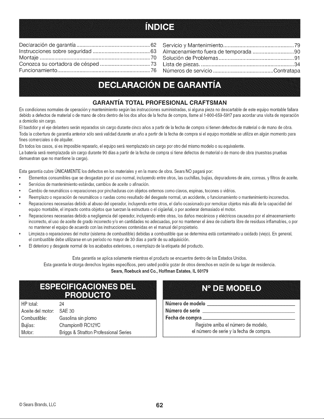
Declaraci6n de garantia .................................................. 62
Instrucciones sobre seguridad ....................................... 63
Montaje ........................................................................... 70
Conozca su cortadora de cesped .................................. 73
Funcionamiento ............................................................... 76
Servicio y Mantenimiento ................................................ 79
Almacenamiento fuera de temporada ............................ 90
Soluci6n de Problemas ................................................... 91
Lista de piezas ................................................................ 34
NL_merosde servicio ......................................... Contratapa
GARANTIA TOTAL PROFESIONAL CRAFTSMAN
En condicionesnormalesde operaci6ny mantenimientoseg_n las instruccionessuministradas,si algunapiezano descartablede esteequipo montanefallara
debidoa defectosde materialo de manode obradentrode los dos aSosde lafecha de compra,Ilameal 1-800-659-5917para acordar unavisita de reparaci6n
a domiciliosin cargo.
El bastidory el eje delanteroserAnreparadossincargo durantecinco a_os a partir de lafecha de comprasi tienen defectosde materialo de manode obra.
Todala coberturade garanfiaanteriors61oserAvalidadduranteun a5o a partir de lafecha de comprasi el equipomontane se utiliza en algOnmomentopara
fines comercialeso de alquiler.
En todoslos casos, si es imposiblerepararlo,el equiposerAreemplazadosin cargo por otro del mismomodeloo su equivalente.
La bateriaserAreemplazadasin cargodurante90 dias a partirde lafecha de comprasi tienedefectosde materialo de mano de obra(nuestraspruebas
demuestranqueno mantienela carga).
Esta garanfiacubre ONICAMENTElos defectosen losmaterialesyen la manode obra.Sears NO pagarApor:
• Elementosconsumiblesque sedesgastanpor el uso normal,incluyendoentreotros, lascuchillas, buj[as,depuradoresde aire,correas, yfiltrosde aceite.
• Serviciosde mantenimientoestAndar,cambiosde aceiteo afinaci6n.
• Cambiode neumAticoso reparacionespor pinchadurascon objetosexternoscomoclavos, espinas,toconeso vidrios.
• Reemplazoo reparaci6ndeneumAticoso ruedascomo resultadodel desgastenormal,un accidente,o funcionamientoo mantenimientoincorrectos.
• Reparacionesnecesariasdebidoal abuso del operador,incluyendoentre otros,el daRoocasionadopor remolcarobjetosmAsalia de la capacidaddel
equipomontane,el impactocontraobjetosquetuerzanla estructurao el cigOe_al,o por acelerardemasiadoel motor.
• Reparacionesnecesariasdebidoa negligenciadel operador,incluyendoentreotras, losda_os mecAnicosyelectricoscausadosporel almacenamiento
incorrecto,el uso deaceitede gradoincorrectoy/o en cantidadesno adecuadas,pot no mantenerel Areadecubierta libre de residuosinflamables,o pot
no mantenerel equipode acuerdo conlas instruccionescontenidasen el manualdel propietario.
• Limpiezao reparacionesdel motor(sistemade combustible)debidasa combustibleque se determinaestAcontaminadou oxidado(viejo). En general,
el combustibledebe utilizarseen un periodo no mayorde 30dias a partirde su adquisici6n.
• Eldeterioroy desgastenormalde losacabadosexteriores,o reemplazode laetiquetadel producto.
Estagaranfia seaplica solamentemientrasel productose encuentredentro de los EstadosUnidos.
Estagaranfia leotorga derechoslegalesespecificos,pero usted podriagozarde otrosderechosen raz6nde su lugar deresidencia.
Sears, Roebuck and Co., Hoffman Estates, IL 60179
HP total: 24
Aceitedel motor: SAE30
Combustible: Gasolinasin plomo
Bujias: Champion@RC12YC
Motor: Briggs& StrattonProfessionalSeries
N_rnero de modelo
N_rnero de serie
Fechade cornpra
Registrearribael nOmerode modelo,
el nOmerode seriey la fechade compra.
@SearsBrands,LLC (}2
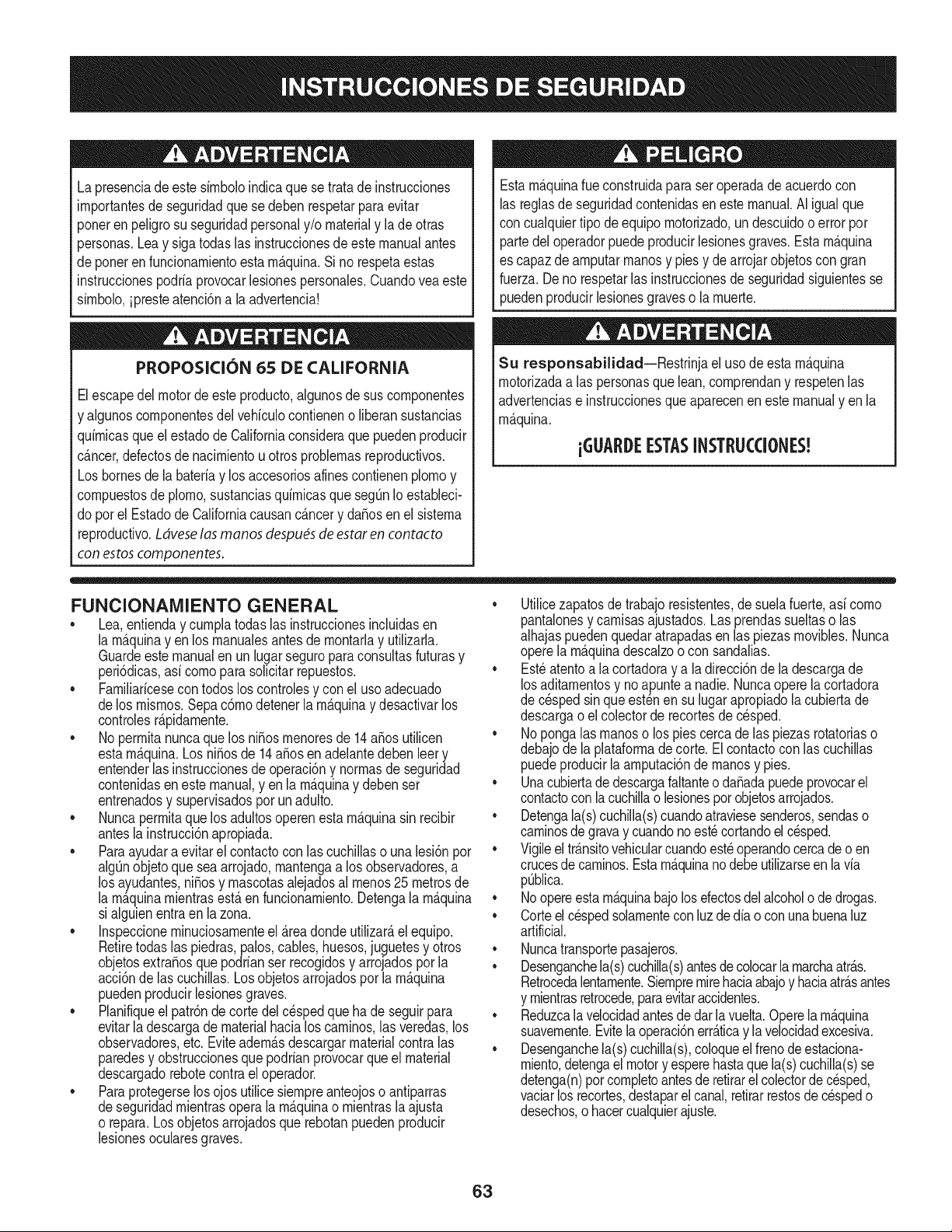
Lapresenciadeeste sirnboloindicaque setrata de instrucciones
irnportantesde seguridadquese deben respetarparaevitar
ponerenpeligrosu seguridadpersonaly/o materialy lade otras
personas.Leay siga todaslas instruccionesde estemanualantes
de poneren funcionarnientoesta rn_.quina.Si no respetaestas
instruccionespodriaprovocarlesionespersonales.Cuandoveaeste
sirnbolo,ipresteatenci6na la advertencia!
PROPOSICION 65 DE CALIFORNIA
Elescapedel motordeesteproducto,algunosde suscornponentes
y algunoscornponentesdel vehiculocontieneno liberan sustancias
quirnicasqueelestadode Californiaconsideraque puedenproducir
c_.ncer,defectosde nacirnientouotrosproblernasreproductivos.
Losbornesdela bateriay los accesoriosdines contienenplornoy
cornpuestosde plorno,sustanciasquirnicasque seg_nIo estableci-
do pot el Estadode Californiacausanc_.ncery da_osenel sisterna
reproductivo.Ldveselas manos despu_sde estaren contacto
con estoscomponentes.
Estarn_.quinarueconstruidaparaseroperadadeacuerdocon
las reglasde seguridadcontenidasenestemanual.AI igualque
concualquiertipo deequipornotorizado,un descuidoo error por
partedeloperadorpuedeproducirlesionesgraves.Estarn_.quina
es capazde arnputarrnanosy piesy dearrojarobjetoscon gran
fuerza.Deno respetarlas instruccionesde seguridadsiguientesse
puedenproducirlesionesgraveso larnuerte.
Su responsabilidad--Restrinja el usode estarn_.quina
rnotorizadaalas personasque lean,cornprendany respetenlas
advertenciase instruccionesque aparecenen estemanualyen la
rn_.quina.
iGI.IARI)E ESTASINSTRUCCIONES!
FUNCIONAIVIIENTO GENERAL
• Lea,entienday curnplatodaslas instruccionesincluidasen
la rn_.quinayen los rnanualesantes de rnontarlay utilizarla.
Guardeestemanualenun lugarseguroparaconsultasfuturasy
peri6dicas,asi cornoparasolicitarrepuestos.
• Farniliaricesecontodoslos controlesy con el usoadecuado
delos rnisrnos.Sepa c6rnodetenerlarn_.quinay desactivarlos
controlesr_.pidarnente.
• No perrnitanuncaque los ni_osrnenoresde 14a_osutilicen
estarn_.quina.Los ni_osde 14a_osen adelantedeben leer y
entenderlas instruccionesde operaci6ny norrnasdeseguridad
contenidaseneste manual,yen la rn_.quinay debenser
entrenadosy supervisadospor un adulto.
• Nuncaperrnitaque los adultosoperenestarn_.quinasin recibir
antesla instrucci6napropiada.
• Paraayudaraevitarel contactocon las cuchillaso una lesi6npor
algQnobjetoquesea arrojado,rnantengaa los observadores,a
los ayudantes,ni_osy rnascotasalejadosal rnenos25 metrosde
la rn_.quinarnientrasest,.en funcionarniento.Detengala rn_.quina
si alguienentraen lazona.
• Inspeccionerninuciosarnenteel Areadondeutilizar_,el equipo.
Retiretodaslas piedras,palos,cables,huesos,juguetesy otros
objetosextra_osquepodrianser recogidosy arrojadospor la
acci6nde las cuchillas.Losobjetosarrojadospor larn_.quina
puedenproducirlesionesgraves.
• Planifiqueel patr6ndecortedel c_spedque ha de seguirpara
evitarla descargade materialhacialoscarninos,las veredas,los
observadores,etc.Eviteadern_.sdescargarmaterialcontralas
paredesy obstruccionesquepodrianprovocarqueel material
descargadorebotecontrael operador.
• Paraprotegerselos ojos utilicesiernpreanteojoso antiparras
deseguridadrnientrasoperalarn_.quinao rnientraslaajusta
o repara.Losobjetosarrojadosque rebotanpuedenproducir
lesionesocularesgraves.
• Utilicezapatosde trabajoresistentes,desuelafuerte,asi corno
pantalonesy carnisasajustados.Las prendassueltaso las
alhajaspuedenquedaratrapadasenlas piezasrnovibles.Nunca
operela rn_.quinadescalzoo con sandalias.
• Est_atentoa lacortadoray a la direcci6nde la descargade
losaditarnentosy noapuntea nadie.Nuncaopere la cortadora
de c_spedsin queest_nen su lugarapropiadola cubiertade
descargao elcolectorde recortesdecesped.
• Nopongalasrnanoso lospies cercade las piezasrotatoriaso
debajode la plataforrnadecorte. Elcontactocon las cuchillas
puedeproducirla arnputaci6ndernanosy pies.
• Unacubiertade descargafaltanteo da_adapuedeprovocarel
contactocon la cuchillao lesionespot objetosarrojados.
• Detengala(s)cuchilla(s)cuandoatraviesesenderos,sendaso
carninosde gravay cuandonoest_cortandoel cesped.
• Vigileel tr_.nsitovehicularcuandoest_operandocercade o en
crucesde carninos.Estarn_.quinanodebe utilizarseen lavia
pQblica.
• Noopereestarn_.quinabajolosefectosdelalcoholode drogas.
• Corteel cespedsolarnentecon luzde dia o conuna buenaluz
artificial.
• Nuncatransportepasajeros.
• Desenganchela(s)cuchilla(s)antesdecolocarla rnarchaatr_.s.
Retrocedalentarnente.Siernpremirehaciaabajoy haciaatr_.santes
y rnientrasretrocede,paraevitaraccidentes.
• Reduzcala velocidadantesdedarlavuelta.Operelarn_.quina
suavernente.Evitelaoperaci6nerr_.ticay la velocidadexcesiva.
• Desenganchela(s)cuchilla(s),coloqueelfrenodeestaciona-
rniento,detengaelmotory esperehastaquela(s)cuchilla(s)se
detenga(n)porcornpletoantesderetirarelcolectorde c_sped,
vaciarlos recortes,destaparelcanal,retirarrestosde cespedo
desechos,o hacercualquierajuste.
63
• Nuncadejelarn_.quinaen funcionarnientosinvigilancia.Apague
siernprelascuchillas,coloqueel frenodernano,detengael motory
retirela Ilaveantesde bajarsedel vehiculo.
• Tengasurnocuidadoal cargaro descargarlarn_.quinaen un
rernolqueocarni6n.Estaunidadnodebeconducirseen ascensoo
descensoderarnpas,porquepodrialadearsey provocarlesiones
personalesgraves.Enlas rarnpasla rn_.quinasedebe ernpujar
rnanualrnenteparacargarlao descargarlacorrectarnente.
• Elsilenciadory el motorse calientany puedencausarquernaduras.
Nolos toque.
• Reviseel espaciolibrepot encirnade la cabezaantesdeconducir
bajolas rarnasbajasde _.rboles,cables,cerrarnientosde puertas,
etc.enloscualeseloperadorpodriaatorarseo serernpujadofuera
dela rn_.quina,Ioquepodriaresultaren lesionesgraves.
• Desenganchetodoslosernbraguesde los accesoriosy presione
totalrnenteel pedaldel frenoantesdeintentararrancarel motor.
• Larn_.quinaest,.diseSadaparacortarc_spedresidencialnormal,
conunaalturanomayora 10".Nointentecortarcespeddernasiado
crecido,seco(porej.,pastura)ni pilasdehojassecas.El c_sped
y las hojassecaspuedenentraren contactoconel escapedel
motory/o acurnularseen la plataforrnade la cortadoradecesped,
convirti_ndoseen unpeligrodeincendio
• Utilicesolarnenteaccesoriosy aditarnentosaprobadosparaesta
rn_.quinapot elfabricantede larnisrna.Lea,cornprenday siga
todaslasinstruccionesproporcionadasconlosaccesorioso
aditarnentosaprobados.Paraobtenerunalistadelosaccesorios
aprobadosy losarchivosadjuntos,Ilarne1-800-659-5917.
• Losdatosestadsticosrnuestranquelosoperadoresde60 aSos
y rnayoresseven involucradosenunaltoporcentajedelesiones
relacionadascontractorescortacesped.Estosoperadoresdeben
evaluarsu capacidadparaoperarel tractorcortac_spedenforrna
suficienternenteseguraparaprotegersea ellosrnisrnosy a los
dern_.scontralesionesgraves.
Si se presentansituacionesqueno est_.nprevistasen este
manualsea cuidadosoy use el sentidocornQn.Contacto1-800-
659-5917parainforrnaci6ny asistencia.
FUNCIONAiVIIENTO EN PENDIENTES
Las pendientesson unfactorirnportanterelacionadoconaccidentes
porderrapey vuelcosque puedenproducirlesionesgravese incluso
la rnuerte.Laoperaci6nen pendientesrequieremayorprecauci6n.
Si nopuederetrocederen la pendienteo si no se sienteseguro,no
realiceningunaoperaci6ndecorte.
Parasu seguridad,use el indicadordependientesque se incluye
cornopartede este manualpararnedirla pendienteantes de operarla
rn_.quinaen una zonainclinada.Sila pendientees mayorde 15 grados
segQnel rnedidor,noopereestarn_.quinaenese sector,puespodria
causarlesionesgraves.
HagaIo siguiente:
• Podehaciaarribay abajodelas pendientes,nodeforrnatrans-
versal.Tengacuidadocuandocarnbiededirecci6nal operaren
pendiente.
• Est_atentoa loshoyos,surcos,baches,rocas,uotrosobjetos
ocultos.Elterrenodesniveladopuedevoltearla rn_.quina.Elcesped
altopuedeocultarobst_.culos.
Vayaa bajavelocidad.ElijaunavelocidadIosuficienternentebaja,
de rnodoquenotengaquedetenerseohacercarnbiosrnientras
est,.sobrela pendiente.Losneurn_.ticospodrianperdertracci6n
sobrelaspendientesaQncuandolosfrenosfuncionaranapro-
piadarnente.Siernprernantengala rn_.quinaen carnbiornientras
desciendelaspendientes,parapoderfrenarconel motor.
• Sigalas recornendacionesdelfabricanteparalos pesoso contra-
pesosdelas ruedas,pararnejorarlaestabilidaddelarn_.quina.
Pararecornendaciones,Ilarneal 1-800-659-5917.
• Tengaespecialcuidadocon loscolectoresdecespeduotros
aditarnentos.Losrnisrnospuedenrnodificarlaestabilidaddela
rn_.quina.
• Hagaquetodoslos rnovirnientosen laspendientesseanlentosy
graduales.Nocarnbierepentinarnentelavelocidadnila direcci6n.
Unfrenadoo carnbiodevelocidadrepentinospuedencausarque
el frentede larn_.quinase levantey d_unavolteretahaciaatr_.s,Io
quepodriaproducirlesionesgraves.
• Evitearrancaro detenerseenunapendiente.Silosneurn_.ticos
pierdenlatracci6n,desenganchelascuchillasy descienda
lentarnentela pendiente.
No hagaIo siguiente:
• Nogiresobrelas pendientesarnenosqueseanecesario.Sies
posible,girelentarnentey gradualrnenteduranteel descenso.
• Nocorteelc_spedcercade pozos,hundirnientosoterraplenes.La
cortadoradec_spedpuedevolcarserepentinarnentesiunade las
ruedasest,.sobreelhordede unacantilado,zanjao siunhordese
desrnorona.
• Nointenteestabilizarlarn_.quinaponiendoelpieenel suelo.
• Noutiliceuncolectordecespeden pendientesernpinadas.
• Nopodeelcespedh_rnedo.Unarnenortracci6npodriacausar
derrapes.
• Noparadescender.El excesode velocidadpuedehacerqueel
operadorpierdaelcontroldela rn_.quina,ocasionandolesiones
graveseinclusola rnuerte.
• Norernolquecargaspesadasdetr_.sde losaditarnentos(carritode
basuracargado,podadorade rodillos,etc)en pendientesrnayores
de5grados.Cuandosedesplazapendienteabajo,el pesoadicional
tiendeaernpujarel tractory puedehacerquese pierdaelcontrol
delrnisrno(porejernplo,eltractorsepuedeacelerar,se reducela
capacidadparafrenary rnaniobrar,losaccesoriospuedenplegarse
cornouncortaplurnasy hacerqueeltractorvuelque).
NINOS
Puedenocurriraccidentestr_.gicossi el operadornoest,. atentoa la
presenciade niSos.PotIo general,los niSosse sientenatraidospor
estetipo de rn_.quinasy su funcionarniento.Noentiendenlos riesgos
ni los peligros.Nuncaasurnaquelos niSosperrnanecer_.nen el rnisrno
lugardondelosvio pot Qltirnavez.
• Mantengaa losniSosfueradel_.readetrabajoy bajoestricta
vigilanciadeunadultoresponsableadern_.sdelpropiooperador.
Est_alertay apaguela rn_.quinasiunniSoingresaal _.rea.
• Antesy rnientrasest,.retrocediendo,mirehaciaatr_.sy cuidequeno
hayaniSos.
NuncatransporteniSos,aQnconla cuchillaapagada.Podriancaerse
y resultarseverarnenteheridoso interferirconlaoperaci6nsegurade
la rn_.quina.
Tengaextrernaprecauci6ncuandoseaproxirnea esquinasciegas,
portales,arbustos,_.rbolesu otrosobjetosquepuedanirnpedirlever
a unniSoquesecruceenel recorridode larn_.quina.
64
• Paraevitaraccidentesaloperarenrnarchaatr_.s,siernpredesengan-
chelascuchillasantesde colocarrnarchaatr_.s.Siest,.instalado,
el"ModoPrecaucidnMarchaAtr_.s"(hojasdeoperarla rn_.quina,
rnientrasquelospaseosa la inversa)nodebeutilizarsecuandohay
ni_osuotraspersonaspresentes.
• Mantengaa losni_osalejadosde losrnotoresenrnarchao calientes.
Puedensufrirquernadurasconunsilenciadorcaliente.
• RetirelaIlavecuandodejelarn_.quinasinvigilancia,evitequeuna
personasinautorizaci6nlarnaneje.
No perrnitanuncaque los ni_osrnenoresde 14a_osutilicenesta
rn_.quina.Losni_osde 14a_osen adelantedeben leer y entenderlas
instruccionesdeoperaci6ny norrnasde seguridadcontenidaseneste
manual,yen la rn_.quinay debenserentrenadosy supervisadospor
unadulto.
REIVIOLQUE
• Rernolque_nicarnenteconunarn_.quinaquecuenteconun
enganchediseSadopararernolcar.Noacopleequiporernolcado
exceptoenel puntodeenganche.
• SigalasrecornendacionesdelfabricanteenIoque respectaalos
lirnitesdepesode losequiposa rernolcary alrernolqueenpendien-
tes.Pararecornendaciones,Ilarneal 1-800-659-5917.
• Nuncaperrnitala presenciade niSosuotraspersonasdentroosobre
losequiposrernolcados.
• Enlaspendientes,elpesodelequiporernolcadopuedecausar
p_rdidadetraccidny perdidadecontrolde larn_.quina.
• Siernpreuseextrala precauci6nrernolcandoconunarn_.quina
capazdehacervueltasapretadas(p.ejpaseo"devueltacero"-en el
cortacesped).Hagaarnpliasvueltasparaevitaralgato-knifing.
• Despl_.ceselentarnentey dejedistanciaadicionalparafrenado.
• Noparadescender.
SERVIClO
Manejo seguro de la gasolina
Paraevitarlesionespersonaleso daSosrnaterialessea surnarnente
cuidadosoal rnanipularla gasolina.Lagasolinaes surnarnente
infiarnabley sus vaporespuedencausarexplosiones.Se puede
lesionargravernentesi derrarnagasolinasobreustedo sobrela ropa,
ya que_sta se puedeincendiar.L_.vesela piely c_.rnbiesede ropade
inrnediato.
• Utilices61olos recipientesparagasolinaautorizados.
• NuncaIlenelos recipientesenel interiorde unvehiculoo carnidn
o cajade rernolquecon recubrirnientopl_.stico.Coloquesiernpre
los recipientesen el piso y lejosdel vehiculoantes de realizarla
carga.
• Cuandoseafactible, retireel equipoa gasolinadel carni6no
rernolquey II_neloen el suelo.Siestonoes posible,Ileneel
equipoen unrernolqueconun contenedorport_.til,envezde
hacerlocon unaboquilladispensadoradegasolina.
• Mantengala boquillade Ilenadoencontactoconel hordedel
dep6sitode combustibleocon la aberturadel recipienteen todo
rnornento,hastaterrninarla carga. No utiliceundispositivode
boquilladeapertura/cierre.
• Apaguetodosloscigarrillos,cigarros,pipasy otrasfuentesde
cornbustidn.
• Nuncacarguecombustibleenla rn_.quinaenun espaciocerrado.
• Nuncasaquela tapadel combustibleni agreguecombustible
rnientrasel motorest,. calienteo en rnarcha.Dejequeel motor
seenfrie porIornenosdos rninutosantesde volvera cargar
combustible.
• NuncaIleneen excesoel dep6sitode combustible.Lleneel
tanquenorn_.sde 1/2pulgadapordebajode la basedel cuello
del tap6ndecarga,paradejarespaciopara la expansi6ndel
combustible.
• Vuelvaa colocar la tapa dela gasolinay ajQstelabien.
• Lirnpieel combustiblequese hayaderrarnadosobreel motory el
equipo.Trasladelarn_.quinaa otrazona.Espere5 rninutosantes
de encenderelmotor.
• Parareducirel riesgode incendio,rnantengala rn_.quinalirnpia
de pasto,hojasy deacurnulacidnde otros residuos.Lirnpielos
derrarnesdeaceiteo combustibley saquetodoslos residuos
ernbebidosde combustible.
• Nuncaguardelarn_.quinao el recipientede combustibleen un
espaciocerradodondehayafuego,chispaso luz piloto,corno
porejernplodecalentadoresdeagua,calefactoresde arnbientes,
hornos,secadoresde ropau otrosaparatosa gas.
• Dejequelarn_.quinase enfriecinco rninutospor Iornenosantes
de guardarla.
Servicio general
• Nuncaenciendael motoren espacioscerradosoen unazona
con pocaventilacidn.El escapedel motorcontienernondxidode
carbono,ungas inodoroy letal.
• Antesdelirnpiar,repararo inspeccionarla rn_.quina,cornpruebe
que la(s)cuchilla(s)y todaslas partesenrnovirnientose hayan
detenido.Desconecteel cablede la bujfay p6ngalohaciendo
rnasacontrael motorpara evitarque se enciendaaccidental-
rnente.
• Reviseperi6dicarnenteparaasegurarsequelas cuchillasse
detenganporcornpletoenaproxirnadarnentecinco(5) segundos
despu_sdeaccionarel controldedesenganchede la(s)
cuchilla(s).Si las cuchillasnose detienendentrodeeste lapso
de tiernpo,su unidaddeber_,ser reparadaporsu distribuidorde
servicioautorizadoMTD.
• Reviseconfrecuenciael funcionarnientodelsisternadefrenos
ya queest,. sujetoa desgasteporla operaci6nnormal.Ajustey
efectQernantenirnientosegQnse requiera.
65
• Reviselos pernosdemontajedela(s) cuchilla(s)y del motora
intervalosfrecuentesparaverificarqueest_nbienapretados.
Adem_.s,inspeccionevisualmentela(s) cuchilla(s)en buscade
daSos(porejemplo,desgasteexcesivo,abolladuras,rajaduras,
etc.). Reemplacela(s)cuchilla(s)Qnicamentecon lascuchillas
defabricantesde equiposoriginales(O.E.M.)listadasen este
manual.Elusode piezasquenocumplencon las especifi-
cacionesdelequipooriginalpodriatenercomoresultadoun
rendimientoincorrectoy adem_.sponeren riesgola seguridad.
• Lascuchillasdelas podadorassonmuyafiladas.Envuelvala
cuchillao utiliceguantesy extremelasprecaucionescuando
efectQemantenimiento.
Mantengatodoslos pernos,tuercasy tornillosbienajustados
paraasegurarsede quela m_.quinase encuentraen condiciones
segurasde operaci6n.
• Nuncaaltereel sistemade enclavamientode seguridadni
otrosmecanismosde seguridad.Controleperi6dicamenteque
funcionencorrectamente.
Despu_sdegolpearcon algQnobjetoextraSo,detengael motor,
desconecteelcablede la bujfay conecteel motora masa.
Inspeccioneminuciosamentela m_.quinaparaver si est,.daSada.
Repareel daSoantes dearrancary ufilizarla m_.quina.
Nuncatratedehacerajusteso reparacionesa la m&quina
mientrasel motorest&en marcha.
• Loscomponentesdel colectordec_spedy la cubiertade
descarga,estansujetosa desgastey daSosque podriandejar
expuestaspartesen movimientoo permifirque searrojenobjetos.
Paraprotegersuseguridad,verifiquefrecuentementetodos los
componentesy reempl_.celosinmediatamentes61ocon piezasde
los fabricantesdel equipooriginal,listadosen estemanual.El uso
de piezasque nocumplencon las especificacionesdel equipo
originalpodriatenercomoresultadoun rendimientoincorrectoy
adem_.sponeren riesgola seguridad.
• Nocambielaconfiguraci6ndel reguladordel motorni Ioopere
a sobrevelocidad.El reguladordel motorcontrolala velocidad
m_.ximasegurade funcionamientodel motor.
• Mantengao reemplacelasefiquetasde seguridade instrucciones
segQnseanecesario.
Respetelas normasreferentesa la disposici6ncorrectay las
reglamentacionessobregasolina,aceite,etc. paraprotegerel
medicambiente.
• SegQnla Comisi6ndeSeguridadde Productospara el Consu-
midorde los EstadosUnidos(CPSC)y laAgenciade Protecci6n
Ambientalde los EstadosUnidos(EPA),esteproductotieneuna
vida Qtilmediade siete(7) aSos,6 270 horasdefuncionamiento.
AIfinalizarla vida0til media,adquieraunam_.quinanuevao haga
inspeccionaranualmente_staSearsporunou otrodistribuidorde
serviciosparacerciorarsedequetodoslos sistemasmec_.nicos
y de seguridadfuncionancorrectamentey no tienenexcesivo
desgaste.Si noIo hace,puedenproducirseaccidentes,lesiones
o muerte.
NO MODIFIQUE EL MOTOR
Paraevitarlesionesgraveso lamuerte,nomodifiqueel motorbajo
ningunacircunstancia.Si cambiala configuraci6ndel reguladordel
motorel motorpuededescontrolarsey operara velocidadesinsegu-
ras.Nuncacambie la configuraci6ndef_.bricadel reguladordel motor.
AVlSO REFERIDO A EMISIONES
Losmotoresqueest_.ncertificadosy cumplencon las regulaciones
de emisionesfederalesEPAy de CaliforniaparaSORE(Equipos
peque_ostodoterreno)est_.ncertificadosparaoperarcongasolina
comQnsin plomoy puedenincluirlos siguientessistemasde control
de emisiones:Modificaci6nde motor(EM) y catalizadorde tres vias
(TWO)siest_.nequipadosde esa manera.
GUARDACHISPAS
EstamAquinaest,.equipadacon un motorde combusti6ninternay
nodebeser utilizadaen o cercade unterrenoagrestecubiertopor
bosque,malezaso hierbaexceptosi el sistemade escapedel motor
est,.equipadocon un amortiguadordechispasque cumplacon las
leyeslocaleso estatalescorrespondientes,en caso de haberlas.
Si se utilizaun amortiguadorde chispasel operadorIo debemantener
en condicionesde usoadecuadas.Enel Estadode California las
medidasanteriormentemencionadassonexigidaspor Icy (Arficulo
4442del C6digode RecursosPOblicosde California).Esposible
queexistanleyessimilaresenotrosestados.Lasleyesfederalesse
aplicanenterritoriosfederales.
Puedeconseguirelamortiguadorde chispasparael silenciadora
travesdesu distribuidorautorizadode motoreso poni_ndoseen
contactoconel centrode servicioSears.
66
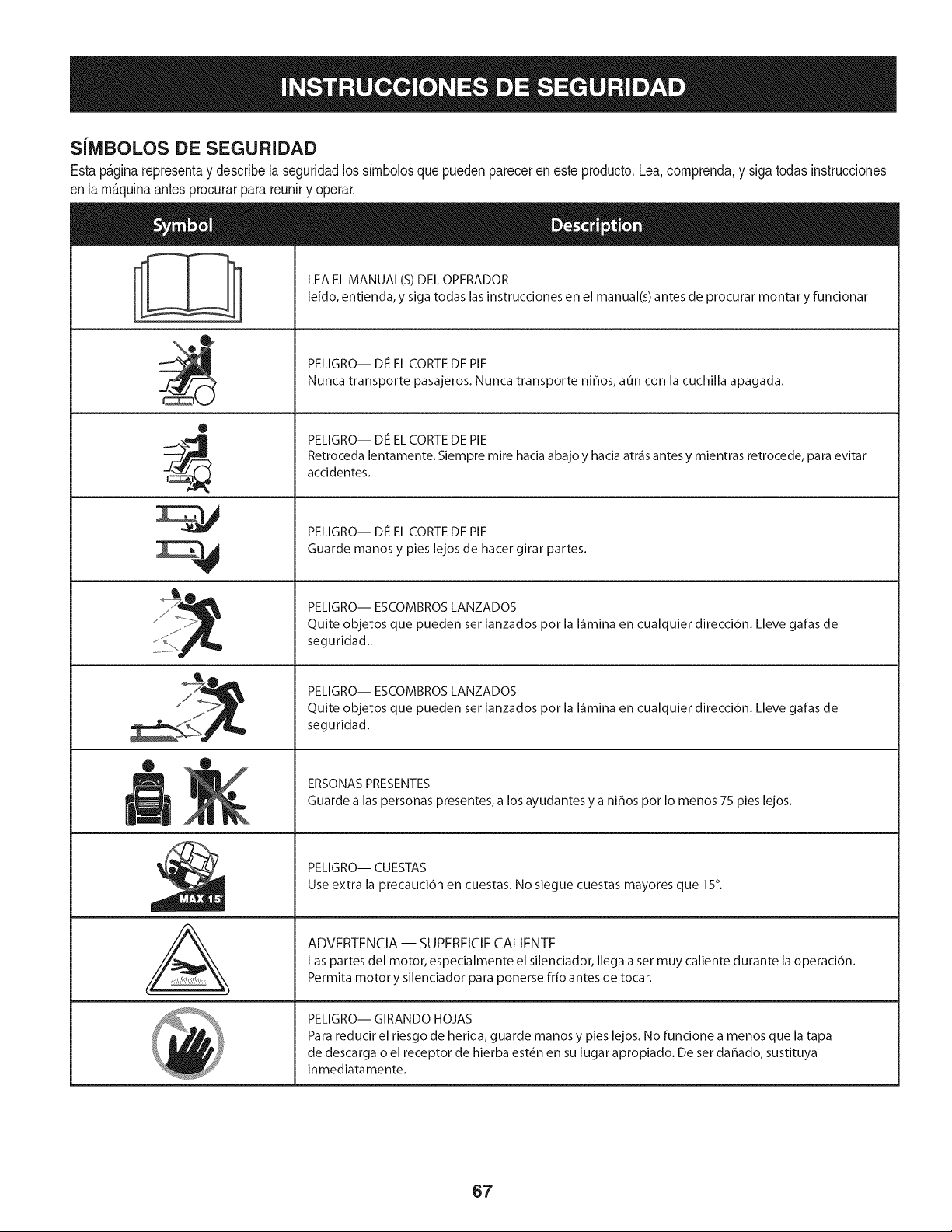
SilVlBOLOS DE SEGURIDAD
Estap&ginarepresentay describelaseguridadlos simbolosquepuedenpareceren este producto.Lea,comprenda,y sigatodas instrucciones
enla m_quinaantesprocurarparareuniry operar.
0
J
AL
LEA EL MANUAL(S) DEL OPERADOR
leido, entienda, y siga todas las instrucciones en el manual(s) antes de procurar montar y funcionar
PELIGRO-- DE EL CORTE DE PIE
Nunca transporte pasajeros. Nunca transporte ni_os, aun con la cuchilla apagada.
PELIGRO-- DE EL CORTE DE PIE
Retroceda lentamente. Siempre mire hacia abajo y hacia atr_is antes y mientras retrocede, para evitar
accidentes.
PELIGRO-- DE EL CORTE DE PIE
Guarde manos y pies lejos de hacer girar partes.
PELIGRO-- ESCOMBROS LANZADOS
Quite objetos que pueden ser lanzados por la I_imina en cualquier direcci6n. Lleve gafas de
seguridad..
PELIGRO-- ESCOMBROS LANZADOS
Quite objetos que pueden ser lanzados por la I_imina en cualquier direcci6n. Lleve gafas de
seguridad.
ERSONAS PRESENTES
Guarde a las personas presentes, a los ayudantes y a ni_os por Io menos 75 pies lejos.
PELIGRO-- CUESTAS
Use extra la precauci6n en cuestas. No siegue cuestas mayores que 15°.
ADVERTENCIA-- SUPERFICIECALIENTE
Las partes del motor, especialmente el silenciador, Ilega a set muy caliente durante la operaci6n.
Permita motor y silenciador para ponerse frio antes de tocar.
PELIGRO-- GIRANDO HOJAS
Para reducir el riesgo de herida, guarde manos y pies lejos. No funcione a menos que la tapa
de descarga o el receptor de hierba est_n en su lugar apropiado. De ser dahado, sustituya
inmediatamente.
67
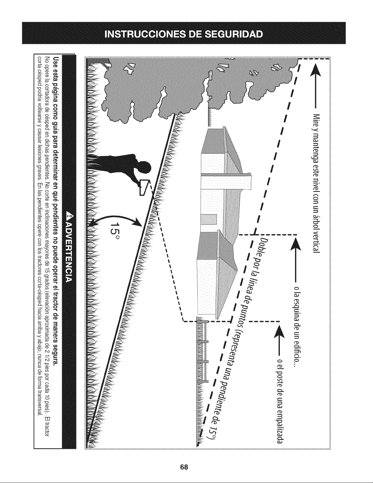
Z
mZ
c3
c3
_._ m.
c3 -_
c3
I
I
I
I
I
I
I
I
68

Estapgtginasemarch6intencionadamenteenblanco.
69
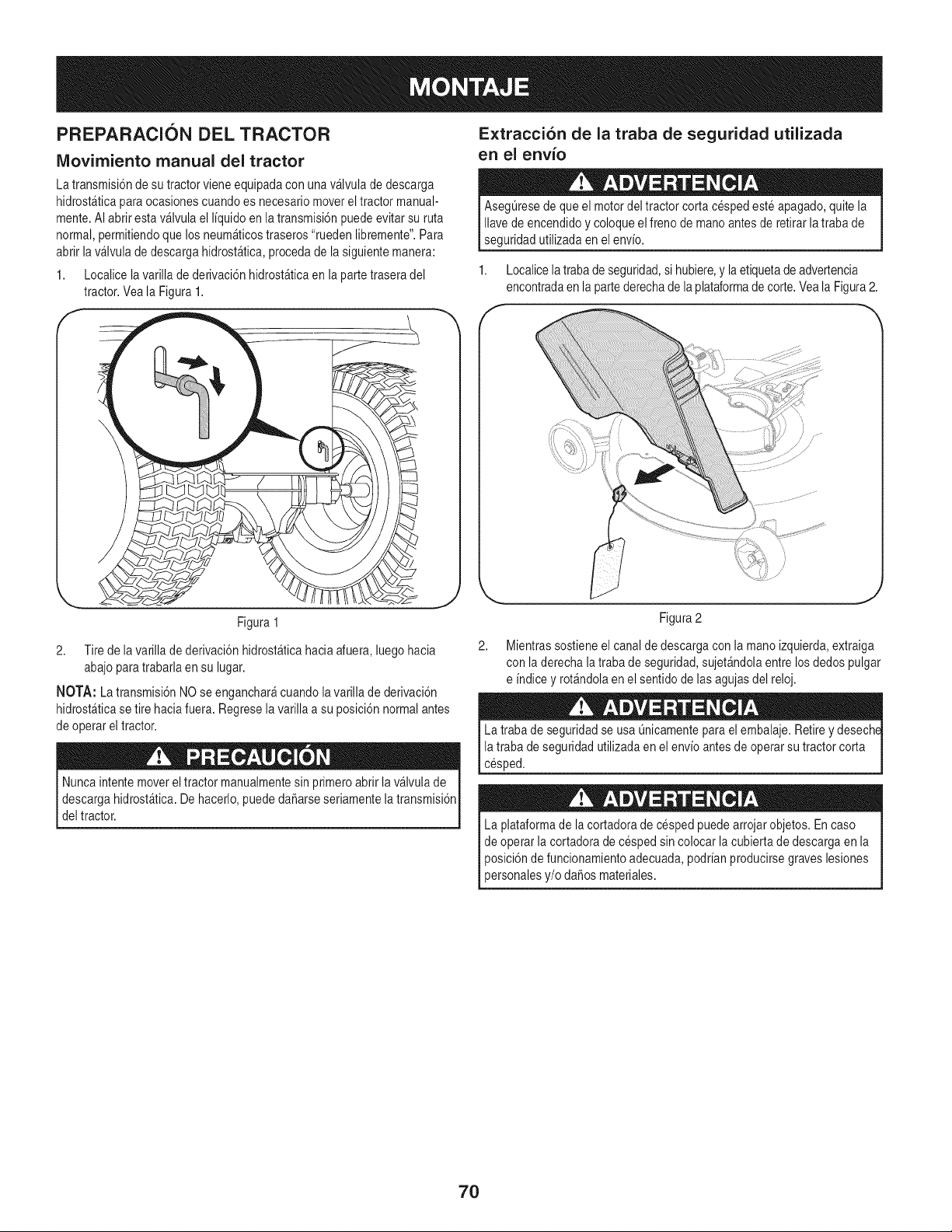
PREPARACION DEL TRACTOR
IViovirniento manual del tractor
Extracci6n de la traba de seguridad utilizada
en el envio
La transmisi6ndesu tractorvieneequipadacon unav_lvulade descarga
hidrost_ticaparaocasionescuandoes necesariomoverel tractor manual-
mente.AI abrirestav_lvula el I[quidoen la transmisi6npuedeevitar su ruta
normal,permitiendoque los neum_ticostraseros"ruedenlibremente".Para
abrir lav_lvula de descarga hidrost_tica,procedade la siguientemanera:
1. Localicelavarilla de derivaci6nhidrost_ticaen la partetraseradel
tractor.Veala Figura1.
AsegL]resede que el motordeltractor corta cespedeste apagado,quitela
Ilavede encendidoy coloque elfreno de manoantesde retirarla trabade
seguridadutilizadaen el env[o.
1. Localicela trabade seguridad,si hubiere,y laetiquetade advertencia
encontradaen la partederechade la plataformade corte.Veala Figura2.
Figura 1
2. Tire de la varillade derivaci6nhidrost_ticahaciaafuera,luego hacia
abajoparatrabarlaen su lugar.
NOTA: La transmisi6nNOse enganchar_cuandolavarilla de derivaci6n
hidrost&ticase tire hacia fuera.Regrese lavarilla a su posici6nnormalantes
de operar el tractor.
Nuncaintentemoverel tractor manualmentesin primeroabrirla v&lvulade
descargahidrost_tica.Dehacerlo,puededaSarseseriamentelatransmisi6n
deltractor.
2,
Figura2
Mientrassostieneel canal de descargacon la manoizquierda,extraiga
con laderecha latrabade seguridad,sujet&ndolaentrelosdedos pulgar
e [ndicey rot_ndolaenel sentidode lasagujasdel reloj.
La traba de seguridadse usa Qnicamentepara el embalaje.Retirey desechE
la trabade seguridad utilizadaen el env[oantes de operar su tractorcorta
cesped.
La plataformade lacortadorade cespedpuedearrojarobjetos.En caso
de operar la cortadorade cesped sincolocar la cubiertade descargaen la
posici6nde funcionamientoadecuada,podr[anproducirsegraves lesiones
personalesy/o daSosmateriales.
7O
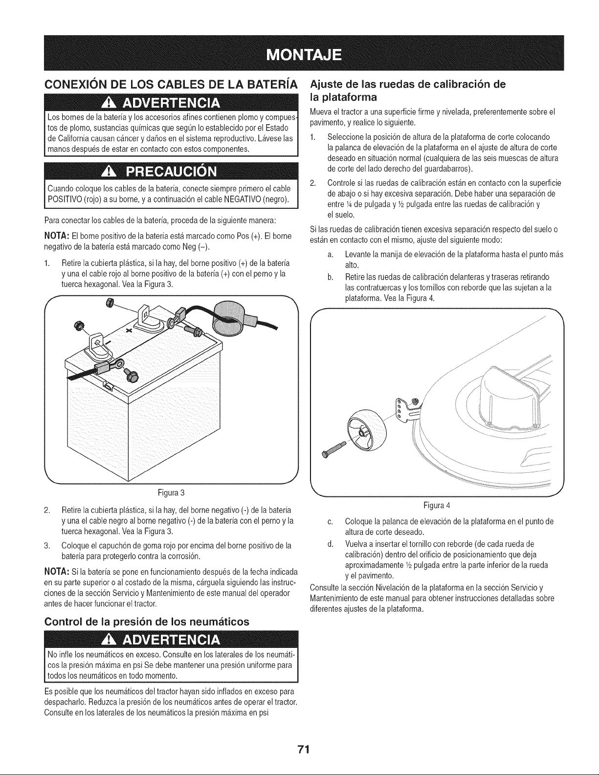
CONEXION DE LOS CABLES DE LA BATERIA
Los bornesde la bateriay losaccesoriosalines contienenplomoy compues-
tos de plomo,sustanciasquimicasque seg0nIo establecidopor el Estado
de Californiacausanc_nceryda_os en el sistemareproductivo.Laveselas
manosdespuesde estar en contactocon estoscomponentes.
Cuandocoloque loscablesde la bateria,conectesiempreprimeroel cable
POSITIVO(rojo)a su borne,y a continuaci6nel cable NEGATIVO(negro).
Paraconectar loscablesdela bateria,proceda de la siguientemanera:
NOTA: El bornepositivode la bateriaest_ marcadocomo Pos (+).El borne
negativode la bateriaest_ marcadocomoNeg (-).
1. Retirela cubiertapl_stica,si la hay,del bornepositivo (+) de la bateria
y unael cablerojo al bornepositivode la bateria(+) con el pernoy la
tuerca hexagonal.Veala Figura3.
f
Figura 3
2. Retirela cubiertapl_stica,si la hay,del bornenegativo(-) de la bateria
y unael cablenegroal borne negativo(-)de la bateriacon el pernoy la
tuerca hexagonal.Veala Figura3.
3. Coloqueel capuch6nde goma rojopor encimadel bornepositivode la
bateriapara protegerlocontralacorrosi6n.
NOTA: Si la bateriase poneen funcionamientodespuesde la fecha indicada
en su partesuperior o al costado de lamisma,c_rguelasiguiendolasinstruc-
clonesde la secci6nServicio y Mantenimientode este manualdel operador
antesde hacerfuncionarel tractor.
Control de la presi6n de los neumaticos
Ajuste de las ruedas de calibraci6n de
la plataforma
Muevaeltractor a unasuperficiefirme y nivelada,preferentementesobre el
pavimento,y realiceIosiguiente.
1. Seleccionela posici6nde altura de la plataformade corte colocando
lapalancade elevaci6nde la plataformaen el ajustede alturade corte
deseadoensituaci6n normal(cualquieradelas seismuescasde altura
de corte del ladoderechodel guardabarros).
2. Controle si las ruedasde calibraci6nest_n en contactocon la superficie
de abajoo si hay excesivaseparaci6n.Debehaberunaseparaci6nde
entre 1_de pulgaday Y2pulgadaentrelas ruedasde calibraci6ny
el suelo.
Si las ruedasdecalibraci6ntienenexcesivaseparaci6nrespectodel sueloo
est_n en contactocon el mismo,ajustedel siguientemodo:
a. Levantela manijade elevaci6ndela plataformahasta el puntom_s
alto.
b. Retirelas ruedasde calibraci6ndelanterasy traseras retirando
lascontratuercasy los tornilloscon rebordeque lassujetana la
plataforma.Veala Figura4.
J
Figura4
c. Coloque lapalanca deelevaci6nde la plataformaen el puntode
altura de cortedeseado.
d. Vuelvaa insertarel tornillocon reborde(de cadaruedade
calibraci6n)dentrodel orificiode posicionamientoque deja
aproximadamenteY2pulgadaentrela parte inferiorde la rueda
y el pavimento.
Consultela secci6nNivelaci6nde la plataformaen la secci6nServicioy
Mantenimientode estemanualparaobtenerinstruccionesdetalladassobre
diferentesajustesde la plataforma.
Noinfle los neum_ticosen exceso.Consulteen los lateralesde losneum_ti-
cos lapresi6nm_ximaen psiSe debe mantenerunapresi6nuniformepara
todos los neumAticosen todo momento.
Es posibleque los neum_ticosdel tractor hayansido infladosen excesopara
despacharlo.Reduzcala presi6nde losneum_ticosantes de operareltractor.
Consulteen los lateralesde los neum_ticosla presi6n m_ximaen psi
71
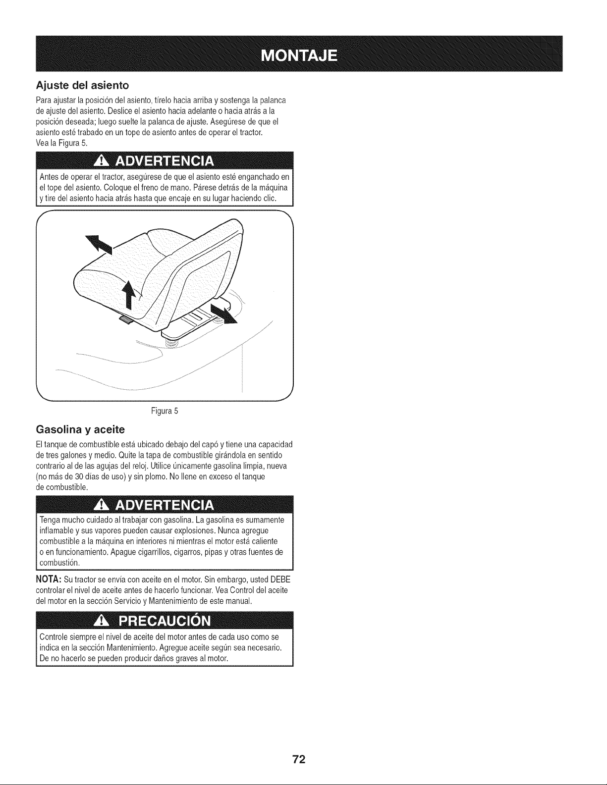
Ajuste del asiento
Para ajustarla posici6ndel asiento,firelo haciaarriba y sostengala palanca
de ajustedel asiento.Desliceel asientohaciaadelanteo haciaatr_s a la
posici6ndeseada;luegosueltela palancade ajuste.AsegQresede que el
asientoeste trabado en untope de asiento antesde operar eltractor.
Veala Figura5.
Antesde operar eltractor, asegQresede que el asientoesteenganchadoen
I eltope del asiento.Coloqueel freno de mano.P&resedetr_sde la m&quina
[y tire del asientohaciaarras hastaque encajeen su lugar haciendoclic.
f
Figura5
J
Gasolina y aceite
Eltanquede combustibleest_ubicadodebajodel cap6 y tiene unacapacidad
de tres galonesy medio.Quitela tapa de combustiblegir&ndolaen sentido
contrarioal de lasagujasdel reloj. UtiliceQnicamentegasolinalimpia, nueva
(no m&sde 30 dias de uso) y sinplomo. NoIleneen excesoel tanque
de combustible.
Tengamucho cuidadoal trabajarcon gasolina.La gasolinaes sumamente
inflamabley susvaporespuedencausarexplosiones.Nuncaagregue
combustiblea la m&quinaen interioresni mientrasel motorest& caliente
o en funcionamiento.Apaguecigarrillos,cigarros,pipas y otrasfuentesde
combusti6n.
NOTA: Su tractorse enviacon aceiteen el motor.Sinembargo,usted DEBE
controlarel nivelde aceiteantesde hacerlofuncionar.VeaControldel aceite
del motoren la secci6nServicioy Mantenimientode este manual.
Controlesiempreel niveldeaceitedel motorantesde cada uso comose
indicaen la secci6nMantenimiento.AgregueaceitesegQnsea necesario.
Deno hacerlose pueden producirdaSosgravesal motor.
72
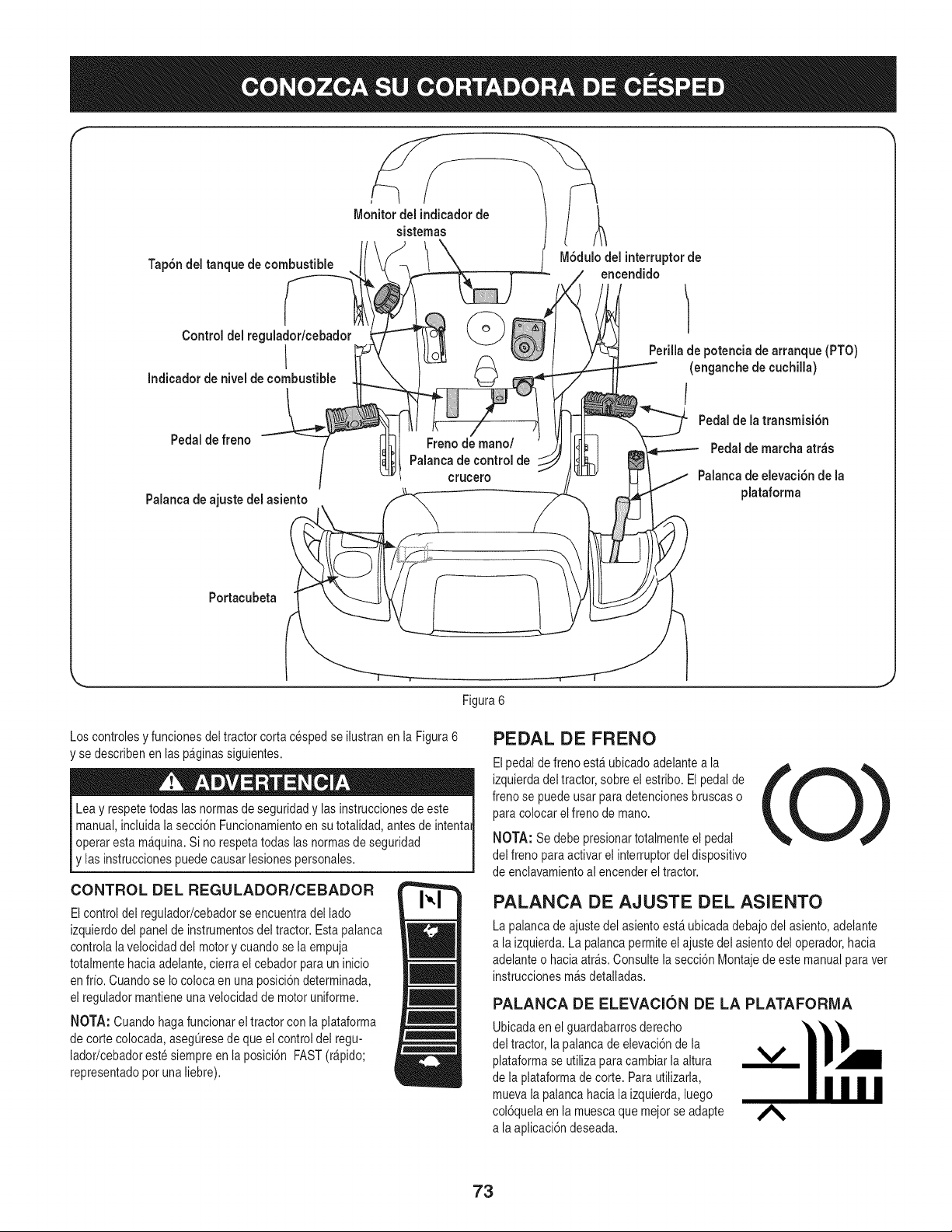
F
Tap6ndel tanque de combustible
M6dulo del interruptorde
encendido
Controldel regulador/cebador
I
Indicador de niveldecombustible
Pedalde freno
Palanca de ajuste del asiento
Freno de mano/
Palanca de control de
crucero
Perilla de potencia de arranque (PTO)
(enganchede cuchilla)
/
Pedal de la transmisidn
Pedalde marcha atr_s
Palanca de elevaciSn de la
plataforma
Portacubeta
\
Figura 6
Los controlesy funcionesdeltractor corta cespedse ilustranen la Figura6
'se describenen laspaginassiguientes.
Leay respetetodaslas normasde seguridady las instruccionesdeeste
manual,incluidala secci6nFuncionamientoen su totalidad,antes de intentai
operaresta m&quina.Si no respetatodas las normasde seguridad
y las instruccionespuedecausar lesionespersonales.
CONTROL DEL REGULADOR/CEBADOR
Elcontroldel regulador/cebadorseencuentradel lado
izquierdodel panelde instrumentosdel tractor. Estapalanca
controlalavelocidaddel motory cuandose la empuja
totalmentehaciaadelante,cierra el cebador para un inicio
en frio. Cuandose Io colocaen una posici6ndeterminada,
el reguladormantieneunavelocidad de motoruniforme.
NOTA: Cuando hagafuncionarel tractorconla plataforma
de corte colocada,asegQresede queel control del regu-
lador/cebadoreste siempreen laposici6n FAST(r_pido;
representadopot una liebre).
PEDAL DE FRENO
Elpedalde freno est_ ubicado adelantea la
izquierdadeltractor, sobreelestribo. El pedalde
frenose puedeusar paradetencionesbruscaso
paracolocar elfreno de mano.
NOTA: Se debe presionartotalmenteel pedal
del freno paraactivar el interruptordel dispositivo
de enclavamientoal encenderel tractor.
PALANCA DE AJUSTE DEL ASIENTO
La palancade ajustedel asientoest&ubicadadebajodel asiento,adelante
a laizquierda.La palancapermiteelajuste del asientodel operador,hacia
adelanteo haciaatr_s. Consultelasecci6nMontajedeestemanualparavet
instruccionesm_sdetalladas.
PALANCA DE ELEVACION DE LA PLATAFORMA
Ubicadaen el guardabarrosderecho
del tractor, lapalancade elevaci6nde la
plataformase utilizapara cambiarlaaltura
de la plataformade corte. Parautilizarla,
muevala palancahaciala izquierda,luego
col6quelaenla muescaque mejorse adapte
a laaplicaci6ndeseada.
73
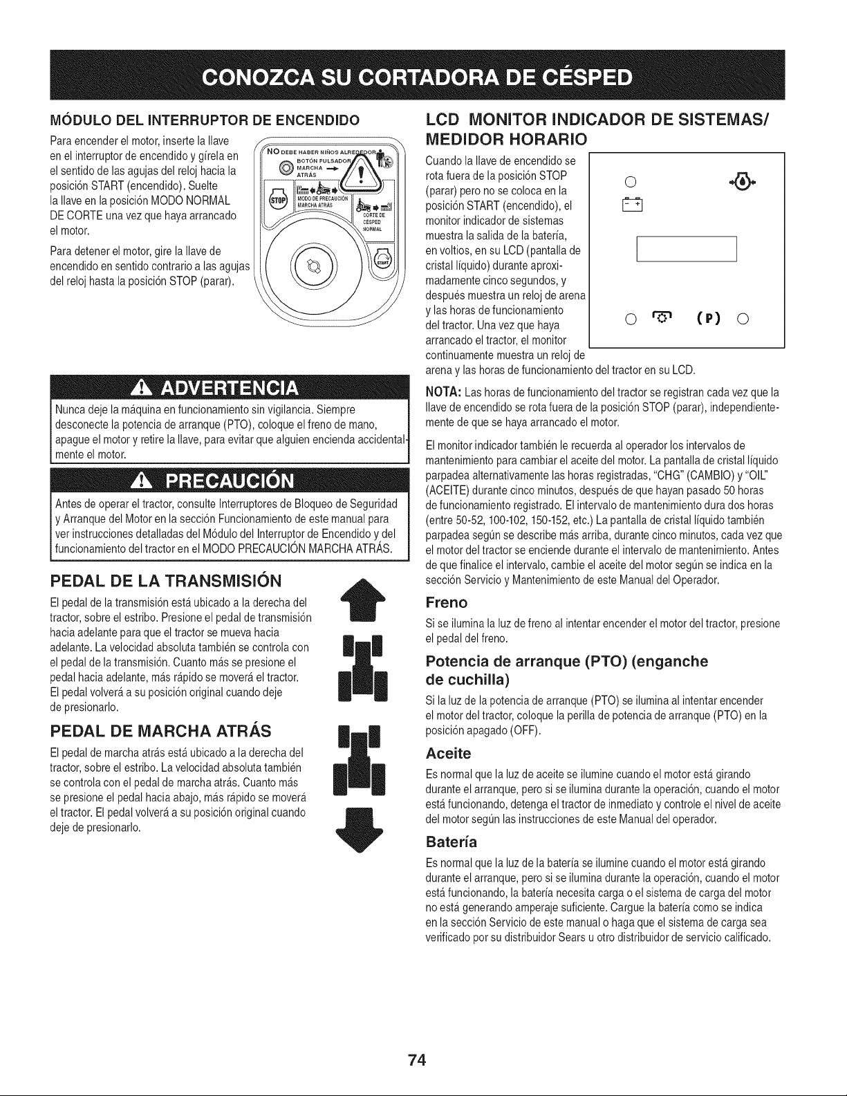
MODULO DEL INTERRUPTOR DE ENCENDIDO
Para encenderel motor,inserte laIlave
en el interruptorde encendidoy girela en
el sentidode lasagujasdel reloj haciala
posici6nSTART(encendido).Suelte
la Ilaveen laposici6nMODONORMAL
DECORTEunavez que hayaarrancado
el motor.
Para detenerel motor,gire la Ilavede
encendidoen sentidocontrarioalas agujas
del relojhasta la _osici6nSTOP(parar).
Nuncadeje la m&quinaen funcionamientosin vigilancia.Siempre
desconectela potenciade arranque(PTO),coloqueel frenode mano,
apagueel motory retirela Ilave, paraevitar quealguien enciendaaccidental.
menteel motor.
Antesde operar eltractor, consulteInterruptoresde Bloqueode Seguridad
y Arranquedel Motoren la secci6n Funcionamientode estemanualpara
vet instruccionesdetalladasdel M6dulodel Interrup!orde Encendidoy,del
_funconamento de tractor en e MODO PRECAUCON MARCHAATRAS.
PEDAL DE LA TRANSMISION
El pedalde la transmisi6nest_ubicadoa laderechadel
tractor,sobre el estribo.Presioneel pedalde transmisi6n
haciaadelanteparaque el tractorse mueva hacia
adelante.La velocidadabsolutatambiense controlacon
el pedalde latransmisi6n.Cuantom&sse presioneel
pedalhaciaadelante,m_sr@ido se mover_eltractor.
El pedalvolver_a su posici6noriginalcuandodeje
de presionarlo.
PEDAL DE MARCHA ATRAS
El pedalde marchaatr&sest&ubicado a la derechadel
tractor,sobre el estribo.La velocidadabsolutatambien
se controlacon el pedalde marchaatr&s.Cuantom&s
se presioneel pedalhaciaabajo,m_s r@idose mover_
eltractor.El pedalvolver_ a su posici6noriginal cuando
dejede presionarlo.
| |
|
LCD MONITOR INDICADOR DE SISTEMAS/
MEDIDOR HORARIO
Cuandola Ilavedeencendidose
rota fuerade la posici6nSTOP
(parar) pero no se colocaen la
posici6nSTART(encendido),el
monitor indicadordesistemas
muestra lasalida de labateria,
en voltios, en su LCD(pantallade
cristal liquido) duranteaproxi-
madamentecincosegundos,y
despuesmuestraun reloj de arena
y las horasde funcionamiento
del tractor. Unavezque haya
arrancadoel tractor,el monitor
continuamentemuestraun reloj de
I
orS" (P) o
arenay las horasde funcionamientodel tractoren su LCD.
NOTA: Las horasde funcionamientodel tractorse registrancadavez que la
Ilavede encendidose rotafuera de la posici6nSTOP(parar),independiente-
mentedeque se hayaarrancadoel motor.
Elmonitorindicadortambien le recuerdaal operadorlos intervalosde
mantenimientoparacambiarel aceitedel motor.La pantalladecristal liquido
parpadeaalternativamentelashorasregistradas,"CHG"(CAMBIO)y "Oil"
(ACEITE)durantecinco minutos,despuesdeque hayanpasado50 horas
de funcionamientoregistrado.El intervalode mantenimientodurados horas
(entre 50-52, 100-102,150-152,etc.) La pantallade cristalliquidotambien
parpadeasegQnse describem_sarriba, durantecinco minutos,cadavez que
el motordel tractor se enciendeduranteel intervalode mantenimiento.Antes
de quefinalice el intervalo,cambieel aceitedel motorsegQnse indica en la
secci6nServicioy Mantenimientode este Manualdel Operador.
Freno
Si se iluminala luz de freno al intentarencenderel motordel tractor,presione
el pedal del freno.
Potencia de arranque (PTO) (enganche
de cuchilla)
Si la luzde la potenciadearranque(PTO)se iluminaal intentarencender
el motordel tractor,coloque la perillade potenciade arranque(PTO) en la
posici6napagado(OFF).
Aceite
Esnormalque la luzde aceitese iluminecuandoel motorest_girando
duranteelarranque,pero si se iluminadurantela operaci6n,cuandoel motor
est&funcionando,detengaeltractor de inmediatoy controleel nivel de aceite
del motorsegQnlas instruccionesde esteManualdel operador.
Bateria
Esnormalque la luzde la bateriase iluminecuandoel motorest_ girando
duranteelarranque,pero si se iluminadurantela operaci6n,cuandoel motor
est&funcionando,la baterianecesitacarga o el sistemade cargadel motor
no est&generandoamperajesuficiente.Carguela bateriacomo se indica
en lasecci6n Serviciode estemanualo hagaque el sistemade cargasea
verificadopotsu distribuidorSears u otro distribuidordeserviciocalificado.
74
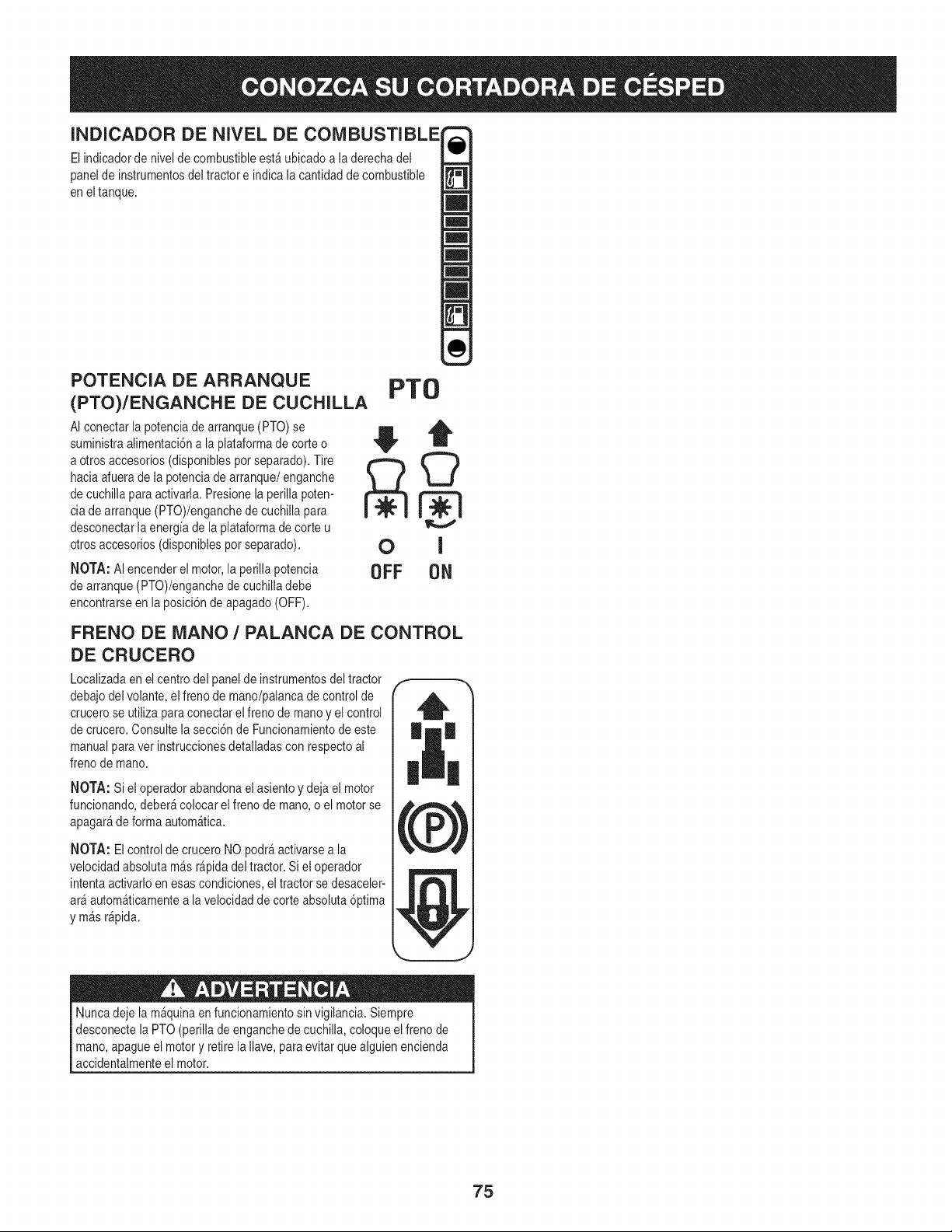
INDICADOR DE NIVEL DE COMBUSTIBLE
El indicadorde niveldecombustibleestA ubicadoa la derechadel
panelde instrumentosdel tractor e indica la cantidadde combustible
en el tanque.
POTENCIA DE ARRANQUE
(PTO)/ENGANCHE DE CUCHILLA
AI conectarla potenciadearranque(PTO) se
suministraalimentaci6na la plataformade corte o
a otros accesorios(disponiblespor separado).Tire
haciaafuerade la potenciadearranque/enganche
de cuchilla paraactivarla. Presionela perillapoten-
ciade arranque(PTO)/enganchede cuchillapara
desconectarla energiade la plataformade corte u
otrosaccesorios(disponiblespot separado).
NOTA: AI encenderel motor,la perillapotencia
de arranque(PTO)/enganchede cuchilladebe
encontrarseenla posici6nde apagado(OFF).
PTO
OFF 0N
FRENO DE MANO / PALANCA DE CONTROL
DE CRUCERO
Localizadaenel centrodel panelde instrumentosdeltractor
debajodel volante,el frenode mano/palancade control de
crucerose utilizapara conectarel frenode manoy el control
de crucero.Consultela secci6nde Funcionamientode este
manualparaver instruccionesdetalladascon respectoal
frenodemano.
NOTA: Si el operadorabandonael asientoy dejael motor
funcionando,deber_colocar elfreno de mano,o el motorse
apagar_de forma autom_tica.
NOTA: El controlde cruceroNO podr&activarsea la
velocidadabsolutam&s r&pidadel tractor.Si el operador
intentaactivarloen esascondiciones,el tractor se desaceler-
ar_ autom_ticamentea la velocidadde corte absoluta6prima
y m_sr_pida.
Nuncadeje la m&quinaen funcionamientosinvigilancia.Siempre
desconecte laPTO(perilla de enganchedecuchilla,coloque elfreno de
mano,apagueel motory retirela Ilave,paraevitarque alguienencienda
accidentalmenteel motor.
75
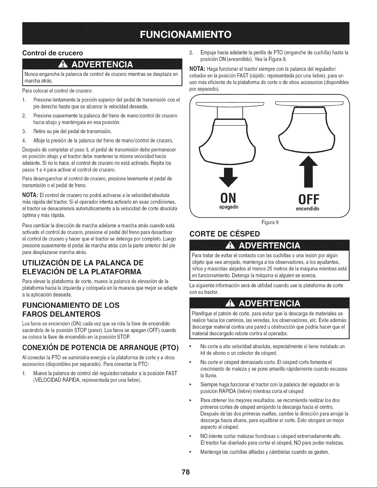
Control de crucero
Nuncaenganchela palancade controlde crucero mientrasse desplazaen
marchaarras.
Para colocarel controlde crucero:
1. Presionelentamentelaporci6n superiordel pedalde transmisi6nconel
pie derechohastaque se alcancela velocidaddeseada.
2. Presionesuavementela palancadel frenode mano/controlde crucero
haciaabajoy mantengalaen esa posici6n.
3. Retiresu pie del pedaldetransmisi6n.
4. Afloje la presi6nde la palancadel frenode mano/controlde crucero.
Despuesde completarel paso3, el pedal detransmisi6ndebe permanecer
en posici6nabajoy el tractordebe mantenerla mismavelocidad hacia
adelante.Si no Io hace,el controlde crucerono est_activado. Repitalos
pasos1 a 4 paraactivarel control de crucero.
Para desengancharel control de crucero,presionelevementeel pedal de
transmisi6no elpedal de freno.
NOTA: Elcontrol de crucerono podr_activarsea la velocidadabsoluta
m_sr@ida del tractor.Si el operadorintentaactivarloen esascondiciones,
eltractor se desacelerar_autom_ticamentea la velocidaddecorte absoluta
6primay m_s r@ida.
Para cambiarla direcci6nde marchaadelantea marchaarrascuandoest_
activadoel controlde crucero,presioneel pedaldel frenoparadesactivar
el controlde cruceroy hacerque el tractorse detengapot completo.Luego
presionesuavementeel pedal de marchaarrascon la parteanteriordel pie
para desplazarsemarchaarras.
UTILIZACION DE LA PALANCA DE
ELEVACION DE LA PLATAFORiVlA
Para elevarla plataformade corte, mueva la palancade elevaci6nde la
plataformahaciala izquierday col6quelaen la muescaque mejorse adapte
a la aplicaci6ndeseada.
FUNCIONAIVlIENTO DE LOS
FAROS DELANTEROS
Los farosse encienden(ON) cadavez queserota la Ilavede encendido
sac_ndolade la posici6nSTOP (parar).Losfaros se apagan(OFF)cuando
se coloca la Ilavedeencendidoen la posici6nSTOR
CONEXIC)N DE POTENCIA DE ARRANQUE (PTO)
AIconectar la PTOsesuministraenergiaa la plataformade corte ya otros
accesorios(disponiblespotseparado).Paraconectarla PTO:
1. Muevala palancade controldel regulador/cebadora la posici6nFAST
(VELOCIDADR_,PIDA,representadapot una liebre).
2. Empujehaciaadelantela perillade PTO(enganchede cuchilla)hasta la
posici6nON (encendido).Veala Figura9.
NOTA: Hagafuncionarel tractor siemprecon la palancadel regulador/
cebadoren la posici6nFAST(r@ido; representadaporuna liebre),paraun
uso m_seficientede la plataformadecorte o de otros accesorios(disponibles
pot separado).
f
ON OFF
apagado encendido
_,,, J
Figura9
CORTE DE CESPED
• A
Paratratarde evitarel contactocon lascuchillaso una lesi6n pot algQn
objeto quesea arrojado,mantengaa los observadores,a losayudantes,
ni_osy mascotasalejadosal menos25 metrosde la m_quinamientrasest_
en funcionamiento.Detengala m_quinasi alguiense acerca.
La siguienteinformaci6nser_de utilidadcuandouse laplataformade corte
con su tractor.
Planifiqueel patr6nde corte,paraevitarque ladescargade materialesse
realice hacialoscaminos,lasveredas, losobservadores,etc. Eviteadem_s
descargarmaterialcontrauna paredu obstrucci6nquepodria hacerque el
materialdescargadorebotecontrael operador.
• No corte a alta velocidadabsoluta,especialmentesi tiene instaladoun
kit deabonoo un colectorde cesped.
• No corte el cespeddemasiadocorto. Elcesped cortofomenta el
crecimientode malezay se pone amarillor@idamentecuandoescasea
la Iluvia.
• Siemprehaga funcionareltractor con la palanca del reguladoren la
posici6nR_,PIDA(liebre) mientrascorta el cesped
• Paraobtener losmejoresresultados,se recomiendarealizarlosdos
primeroscortes de cespedarrojandoladescargahaciael centro.
Despuesde las dos primerasvueltas,cambieladirecci6nparaarrojarla
descarga haciaafuera, para equilibrarel corte. Estootorgar_un mejor
aspectoalcesped.
• NO intentecortar malezasfrondosaso cespedextremadamentealto.
Eltractorfue diseSadopara cortar el cesped,NO para podarmalezas.
,, Mantengalascuchillasafiladasy c_mbielascuandose gasten.
78
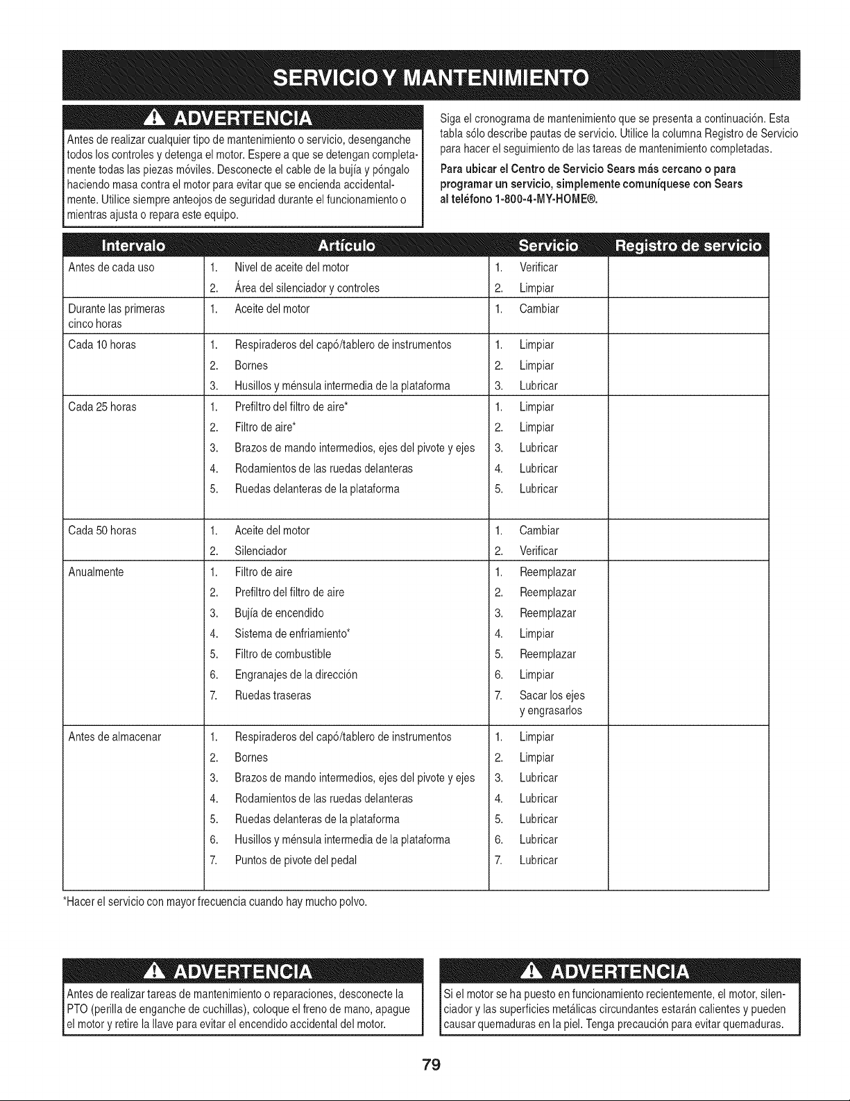
Antesde realizarcualquiertipo demantenimientoo servicio,desenganche
todos loscontrolesydetenga el motor.Esperea que sedetengancompleta-
mentetodaslas piezas m6viles.Desconecteel cablede la bujia y p6ngalo
haciendomasacontrael motorparaevitarque se enciendaaccidental-
mente.Utilicesiempreanteojosde seguridadduranteel funcionamientoo
mientrasajustao repara este equipo.
Siga el cronogramademantenimientoque se presentaa continuaci6n.Esta
tabla s61odescribepautasde servicio.Utilice la columnaRegistrode Servicio
para hacerel seguimientode lastareas de mantenimientocompletadas.
Para ubicar el Centro de Servicio Sears m_s cercano o para
programar un servicio, simplemente comuniquese con Sears
al tel_fono 1-800-4-MY-HOME®.
Antesde cada uso
Durantelas primeras
cinco horas
Cada10 horas
Cada25 horas
Cada50 horas
Anualmente
1. Nivelde aceitedel motor
2. Areadelsilenciadorycontroles
1. Aceite del motor
1. Respiraderosdel cap6/tablerode instrumentos
2. Bornes
3. Husillosy mensulaintermediade la plataforma
1. Prefiltrodel filtro de aire*
2. Filtrode aire*
3. Brazosde mandointermedios,ejes del pivotey ejes
4. Rodamientosde lasruedasdelanteras
5. Ruedasdelanterasdela plataforma
1. Aceite del motor
2. Silenciador
1. Filtrode aire
2. Prefiltrodel filtro de aire
3. Bujia de encendido
4. Sistemadeenfriamiento*
5. Filtrode combustible
6. Engranajesdela direcci6n
7. Ruedastraseras
1. Respiraderosdel cap6/tablerode instrumentos
2. Bornes
3. Brazosde mandointermedios,ejes del pivotey ejes
4. Rodamientosde lasruedasdelanteras
5. Ruedasdelanterasdela plataforma
6. Husillosy mensulaintermediade la plataforma
7. Puntosdepivotedel pedal
Antesde almacenar
1. Verificar
2. Limpiar
1. Cambiar
1. Limpiar
2. Limpiar
3. Lubricar
1. Limpiar
2. Limpiar
3. Lubricar
4. Lubricar
5. Lubricar
1. Cambiar
2. Verificar
1. Reemplazar
2. Reemplazar
3. Reemplazar
4. Limpiar
5. Reemplazar
6. Limpiar
7. Sacar losejes
y engrasarlos
1. Limpiar
2. Limpiar
3. Lubricar
4. Lubricar
5. Lubricar
6. Lubricar
7. Lubricar
*Hacerel serviciocon mayorfrecuenciacuandohay muchopolvo.
Antesde realizar tareasde mantenimientoo reparaciones,desconectela
PTO(perilla de enganchede cuchillas),coloqueel freno de mano,apague
el motory retirela Ilaveparaevitarel encendidoaccidentaldel motor.
Si el motorse ha puesto en funcionamientorecientemente,el motor,silen-
ciador y lassuperficiesmet_licascircundantesestar_ncalientesy pueden
causar quemadurasen la piel.Tengaprecauci6npara evitarquemaduras.
79
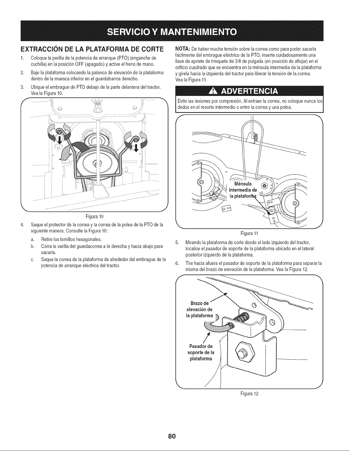
EXTRACCIONDE LA PLATAFORIVlA DE CORTE
1. Coloquela perillade lapotenciade arranque(PTO) (enganchede
cuchilla)en la posici6nOFF (apagado)y activeel frenode mano.
2. Baje la plataformacolocandola palancade elevaci6nde la plataforma
dentrode la muescainferioren el guardabarrosderecho.
3. Ubiqueelembraguede PTOdebajode la partedelanteradel tractor.
Veala Figura10.
4,
Figura 10
Saqueel protectorde la correay la correade la poleade la PTOde la
siguientemanera.Consultela Figura 10:
a. Retirelostomillos hexagonales.
b. Corra lavarilla del guardacorreaa la derechay haciaabajopara
sacarla.
c. Saquelacorreade la plataformade alrededordel embraguede la
potenciade arranqueelectricadel tractor.
NOTA: De habermucha tensi6nsobrela correacomo parapodersacarla
f_cilmentedel embragueelectrico de la PTO,inserte cuidadosamenteuna
Ilavede aprietede trinquetede 3/8de pulgada(en posici6ndeaflojar)en el
orificiocuadradoquese encuentraen la mensulaintermediade laplataforma
y girela haciala izquierdadel tractor paraliberarla tensi6nde la correa.
Veala Figura 11.
Evitelas lesionespor compresi6n.AIextraer la correa,no coloquenunca los
dedos enel resorte intermedioo entrela correay unapolea.
F
Figura11
5. Mirando la plataformade corte desdeel lado izquierdodel tractor,
Iocaliceel pasadorde soportede la plataformaubicadoen el lateral
posteriorizquierdode la plataforma.
6. Tire haciaafuera elpasadorde soportede la plataformapara separarla
mismadel brazode elevaci6nde la plataforma.Veala Figura12.
Brazo de
elevaci6n de
la plataforma
Pasador de
soporte de la
plataforma
Figura12
8O
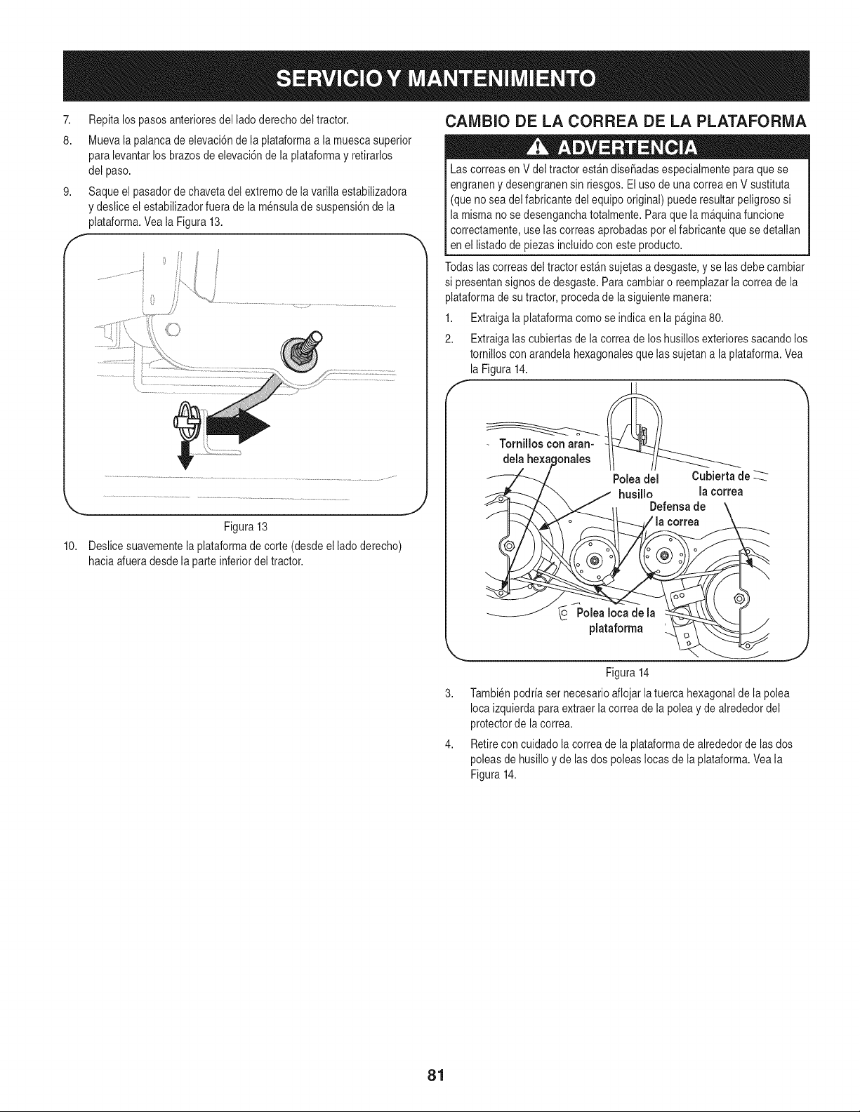
7. Repita lospasosanterioresdel ladoderechodel tractor.
8. Muevala palancade elevaci6nde la plataformaa la muescasuperior
para levantarlos brazosde elevaci6nde la plataformay retirarlos
del paso.
9. Saqueel pasadorde chavetadel extremode lavarillaestabilizadora
y deslice el estabilizadorfuerade la mensulade suspensi6nde la
plataforma.Vea la Figura13.
f
Figura 13
10. Deslicesuavementela plataformade corte (desdeel lado derecho)
haciaafueradesdela parteinferiordel tractor.
CAMBIO DE LA CORREA DE LA PLATAFORMA
Las correasen V deltractor est_ndise_adasespecialmenteparaque se
engraneny desengranensin riesgos.Eluso de unacorreaen V sustituta
(que no sea delfabricantedel equipooriginal) puederesultarpeligrososi
la mismano se desenganchatotalmente.Paraque la m_quinafuncione
correctamente,use las correasaprobadaspotel fabricanteque se detallan
en el listadode piezasincluidocon esteproducto.
Todaslascorreasdel tractor est_nsujetasa desgaste,y se lasdebe cambiar
si presentansignos de desgaste.Paracambiaro reemplazarla correade la
plataformade su tractor,procedade la siguiente manera:
1. Extraigala plataformacomo se indica en la pagina80.
2. Extraigalas cubiertasde la correade loshusillosexterioressacandolos
tornilloscon arandela hexagonalesque lassujetana la plataforma.Vea
la Figura14.
Tornilloscon aran-
dela he×at
Polea del Cubierta de --_._-_
husillo la correa
Defensade
la correa
PoleaIoca de la
plataforma
Figura14
Tambienpodriaser necesarioaflojar latuerca hexagonalde la polea
Iocaizquierdaparaextraerla correade la poleay dealrededordel
protectorde lacorrea.
Retirecon cuidado la correade la plataformade alrededorde las dos
poleasde husilloy de las dos poleasIocasde laplataforma.Veala
Figura14.
81
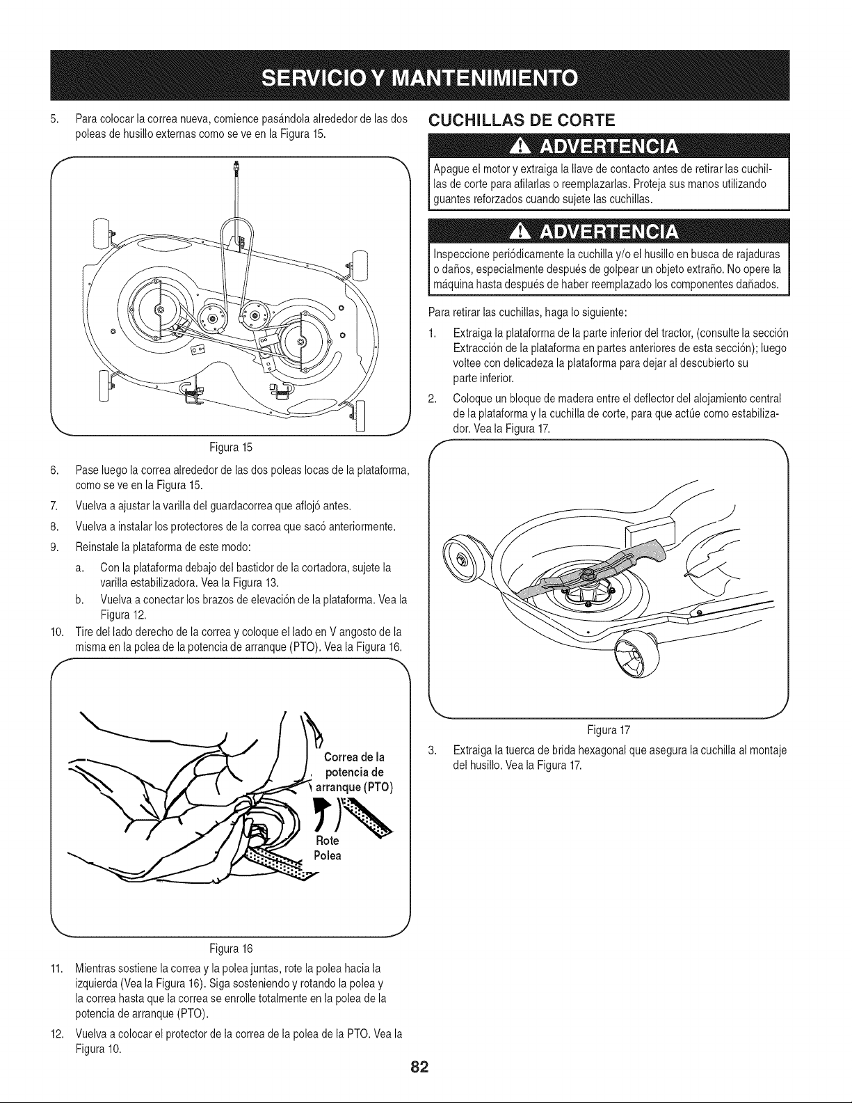
5. Para colocarla correanueva,comiencepas_ndolaalrededorde lasdos CUCHILLAS DE CORTE
poleasde husilloexternascomose ve en la Figura 15.
6. Pase luegola correaalrededorde lasdos poleas Iocasde la plataforma,
comose ve en la Figura15.
7. Vuelvaa ajustarla varilladel guardacorreaque afloj6antes.
8. Vuelvaa instalarlos protectoresde lacorrea quesac6anteriormente.
9. Reinstalela plataformade estemodo:
a. Con la plataformadebajodel bastidorde lacortadora, sujetela
varillaestabilizadora.Veala Figura 13.
b. Vuelvaa conectar losbrazos de elevaci6nde la plataforma.Vea la
Figura 12.
10. Tire del ladoderechode lacorrea y coloqueel ladoen V angostode la
mismaen la poleade la potenciade arranque(PTO).Veala Figura16.
f
Correa de la
potenciade
arranque (PTO)
Rote
Polea
Apagueel motory extraigala Ilavede contactoantes de retirar lascuchil-
las de corte para afilarlaso reemplazarlas.Protejasus manos utilizando
guantesreforzadoscuandosujetelas cuchillas.
Inspeccioneperi6dicamentela cuchillay/o el husilloen buscade rajaduras
o da6os, especialmentedespuesde golpear un objetoextra_o.No operela
m_quinahastadespuesde haber reemplazadoloscomponentesdaSados.
Pararetirar lascuchillas,haga Io siguiente:
1. Extraigala plataformade la parteinferiordel tractor,(consultelasecci6n
Extracci6nde la plataformaen partesanterioresde estasecci6n);luego
volteecon delicadezala plataformapara dejaral descubiertosu
parte inferior.
2. Coloque un bloquede maderaentreel deflectordel alojamientocentral
de la plataformay la cuchillade corte, para que actL]ecomoestabiliza-
dor. Veala Figura17.
f
Figura17
3. Extraigala tuercade brida hexagonalqueasegura lacuchillaal montaje
del husillo.Veala Figura17.
Figura 16
11. Mientrassostiene lacorrea y la poleajuntas,rote la poleahacia la
izquierda(Vea la Figura16). Sigasosteniendoy rotandola poleay
la correahastaque la correase enrolletotalmenteen la poleade la
potenciade arranque(PTO).
12. Vuelvaa colocar el protectorde la correade lapolea de la PTO.Veala
Figura 10.
82
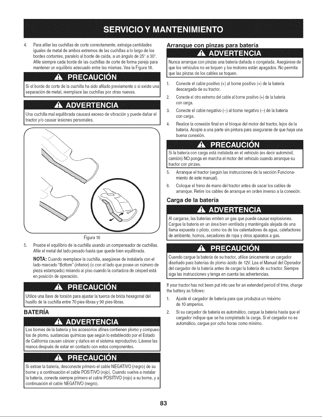
4,
Paraafilar lascuchillasde corte correctamente,extraigacantidades
igualesde metalde ambosextremosde lascuchillasa Io largo de los
hordescortantes,paraleloal hordede ca[da, a un &ngulode25°a 30°.
Afilesiemprecada bordede las cuchillasde corte de forma parejapara
mantenerun equilibrioadecuadoentrelas mismas.Vea la Figura18.
Si el hordede corte de la cuchilla ha sidoafilado previamenteo si existeuna
separaci6nde metal,reemplacelas cuchillaspot otras nuevas.
Unacuchilla mal equilibradacausar&excesode vibraci6ny puededaSarel
tractor y/o causarlesionespersonales.
5,
J
Figura 18
Pruebeel equilibriode lacuchilla usandoun compensadorde cuchillas.
Afileel metal del ladopesadohastaque quedebienequilibrada.
NOTA: Cuando reemplacelacuchilla, asegLiresede instalarlacon el
ladomarcado"Bottom"(inferior)(ocon el ladoque posee unnL_merode
piezaestampado)mirandoal pisocuandola cortadoradecesped est_
en posici6nde operaci6n.
Utilice unaIlavede torsi6nparaajustarlatuercade brida hexagonaldel
husillode lacuchillaentre 70 pies-librasy 90 pies-libras.
BATERiA
Los bornesde la bater[ay losaccesoriosalines contienenplomoy compues-
tos de plomo,sustanciasqu[micasque seg0nIo establecidopor el Estado
de Californiacausanc&ncerydaSosenel sistemareproductivo.Laveselas
manosdespuesde estar en contactocon estoscomponentes.
Si extrae la bater[a,desconecteprimeroel cable NEGATIVO(negro)de su I
borney a continuaci6nel cable POSlTIVO(rojo).Cuandovuelvaa instalar
la bater[a,conectesiempreprimeroel cable POSITIVO(rojo) a su borne,y a
cont nuac6n e cab e NEGATVO (negro). I
Nuncaarranquecon pinzasuna bater[adaSadao congelada. AsegL_resede
que losveh[culosno se toqueny los motoresest_n apagados.Nopermita
que las pinzasde loscables se toquen.
1. Conecteel cablepositivo(+)al bornepositivo (+) de labater[a
descargadade su tractor.
2. Conecteel otroextremodel cableal bornepositivo(+) dela bateria
con carga.
3. Conecteel cablenegativo(-) al borne negativo(-) de la bater[a
con carga.
4. Realicelaconexi6nfinal en el bloquedel motordel tractor,lejos de la
bater[a.Acople a una partesin pinturapara asegurarsede que hayauna
buenaconexi6n.
Si la bater[aconcarga est&instaladaen elveh[culo(es decirautom6vil,
cami6n)NO pongaen marchael motordel veh[culocuandoarranquesu
tractorcon pinzas.
5. Arranqueel tractor (segQnlasinstruccionesde lasecci6n Funciona-
mientode este manual).
6. Coloqueel frenode manodel tractor antesde sacar loscablesde
arranque.Retirelos cables de arranqueen ordeninversoa la conexi6n.
Carga de la bateria
AI cargarse,las bater[asemiten un gasque puedecausarexplosiones.
Carguela bater[aenun &teabien ventiladay mantengalaalejada de una
llamaexpuestao piloto,comolosde los calentadoresde agua,calefactores
de ambiente, hornos,secadoresde ropay otros aparatosa gas.
Cuandocargue labater[ade sutractor, utiliceOnicamenteun cargador
diseSadoparahater[asde plomo-_cidode 12V.Leael Manualdel Operador
del cargadordela bater[aantesde cargarla bater[ade su tractor.Siempre
siga las instruccionesy tenga en cuentalasadvertencias.
If yourtractorhas notbeen putinto use for an extendedperiodof time, charge
the batteryas follows:
1. Ajusteel cargadorde bater[aparaque produzcaunm_ximo
de 10amperios.
2. Si su cargadorde bater[aes autom&tico,carguela bater[ahastaque el
cargadorindiqueque se ha completadola carga. Si el cargadorno es
autom_tico,carguepot ocho horascomo m[nimo.
83
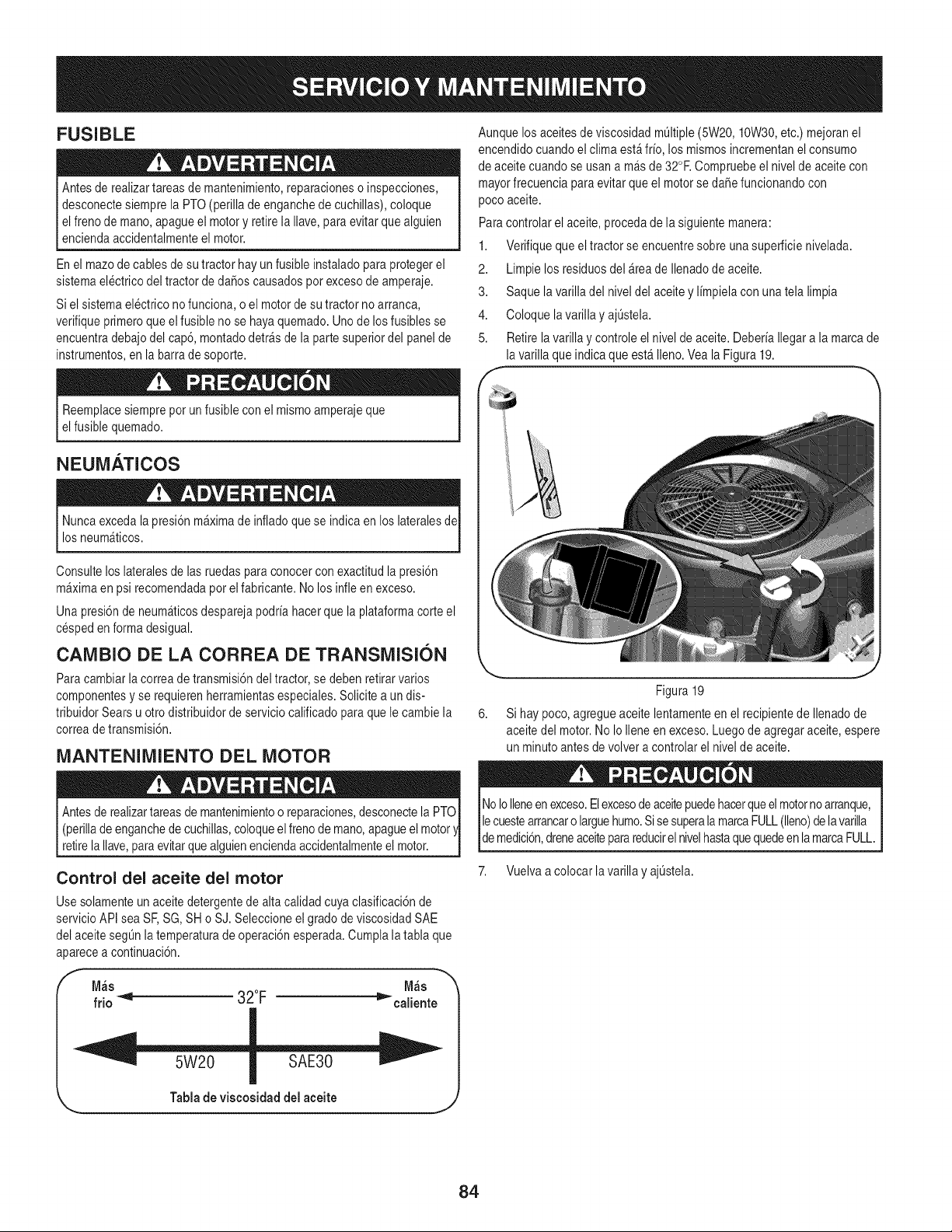
FUSIBLE
Antesde realizartareasde mantenimiento,reparacioneso inspecciones,
desconectesiemprela PTO(perillade enganchede cuchillas),coloque
elfrenode mano,apagueel motory retirela Ilave, paraevitar quealguien
enciendaaccidentalmenteel motor.
En el mazode cablesde sutractor hay un fusibleinstaladopara protegerel
sistemaelectricodel tractorde daSoscausadospotexcesode amperaje.
Siel sistemaelectrico nofunciona, o el motorde su tractornoarranca,
verifiqueprimeroqueel fusibleno se hayaquemado.Unode losfusiblesse
encuentradebajo del cap6,montadodetr_sde la partesuperiordel panel de
instrumentos,en la barrade soporte.
Reemplacesiemprepot un fusiblecon el mismoamperajeque
elfusiblequemado.
NEUMATICOS
Nuncaexceda lapresi6nm_ximade infladoquese indicaen los lateralesde
losneum_ticos.
Consulteloslateralesde las ruedaspara conocercon exactitud la presi6n
m_ximaen psirecomendadapor el fabricante.No los infleen exceso.
Una presi6nde neum_ticosdesparejapodriahacer que la plataformacorte el
cespeden forma desigual.
CAMBIO DE LA CORREA DE TRANSMISION
Para cambiarla correade transmisi6ndel tractor,se debenretirar varios
componentesy se requierenherramientasespeciales.Solicitea un dis-
tribuidorSears u otto distribuidorde serviciocalificadoparaquele cambiela
correadetransmisi6n.
MANTENIMIENTO DEL MOTOR
Antesde realizartareasde mantenimientoo reparaciones,desconectela PTO
(perillade enganchede cuchillas,coloqueelfrenode mano,apagueel motor
retirela Ilave,para evitarque alguienenciendaaccidentalmenteel motor.
Control del aceite del motor
Usesolamenteun aceitedetergentede alta calidadcuya clasificaci6nde
servicioAPI sea SF,SG, SH o SJ.Seleccioneelgrado de viscosidadSAE
del aceitesegOnlatemperaturade operaci6nesperada.Cumpla latabla que
aparecea continuaci6n.
f
M_s M_s
frio _'_ 32°F _"ealiente
Aunquelos aceitesde viscosidadm01tiple(5W20, 10W30,etc.)mejoranel
encendidocuandoel climaest_frio, los mismosincrementanel consumo
de aceitecuandose usana m&sde 32°R Compruebeel niveldeaceite con
mayorfrecuenciaparaevitarqueel motorse daSefuncionandocon
poco aceite.
Paracontrolarel aceite,procedade la siguientemanera:
1. Verifiquequeel tractorse encuentresobre unasuperficienivelada.
2. Limpie losresiduosdel _reade Ilenadode aceite.
3. Saque la varilladel niveldel aceitey limpielacon unatela limpia
4. Coloque lavarillayaj0stela.
5. Retirelavarilla y controleel nivel de aceite.DeberiaIlegara la marcade
la varilla queindica que est_ Ileno.Veala Figura19.
Figura 19
6. Si hay poco,agregueaceitelentamenteen el recipientede Ilenadode
aceitedel motor.No Io Ileneen exceso.Luegode agregaraceite, espere
un minutoantesdevolver a controlarel nivelde aceite.
NoIolleneenexceso.Elexcesodeaceitepuedehacerqueel motorno arranque,
lecuestearrancaro larguehumo.Sisesuperala marcaFULL(lleno)delavarilla
lde medc 6n, dreneacete parareducr e nve hastaquequedeen a marcaFULL.
7. Vuelvaa colocar lavarilla y ajOstela.
Tablade viseosidad del aceite
J
84
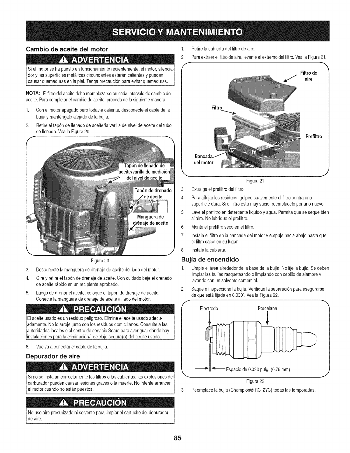
Cambio de aceite del motor
Si el motorse ha puestoenfuncionamientorecientemente,el motor,silencia-
dory las superficiesmet_licascircundantesestar_ncalientesy pueden
causar quemadurasen la piel. Tengaprecauci6nparaevitar quemaduras.
NOTA: El filtrodel aceitedebereemplazarseen cadaintervalode cambiode
aceite.Paracompletarelcambiode aceite,procedade la siguientemanera:
1. Conel motorapagadoperotodaviacaliente,desconecteel cable dela
bujia y mantengaloalejadode la bujia.
2. Retireeltap6n de Ilenadode aceite/lavarilla de nivelde aceitedel tubo
de Ilenado.Vea la Figura20.
1. Retirela cubiertadel filtrode aire.
2. Paraextraerel filtrode aire, levanteelextremodelfiltro.Veala Figura21.
Filtro de
J aire
Filtro
Prefiltro
del motor
Figura20
3. Desconectela manguerade drenajedeaceitedel lado del motor.
4. Gire y retireel tap6n de drenajedeaceite.Con cuidadobajeel drenado
de aceite r@idoen un recipienteaprobado.
5. Luego de drenar elaceite, coloqueel tap6n de drenajede aceite.
Conectela manguerade drenajede aceiteal lado del motor.
instalaciones la eliminaci6n/recicla
6. Vuelvaa conectarelcable de la bujia.
Depurador de aire
del aceite usado.
Si no se instalancorrectamentelosfiltroso lascubiertas,las explosionesdel
carburadorpuedencausar lesionesgraveso la muerte.No intentearrancar
el motorcuandonoest_n puestos.
Figura21
3. Extraigael prefiltrodel filtro.
4. Paraaflojar losresiduos,golpeesuavementeelfiltro contrauna
superficiedura.Si elfiltro est_muysucio,reempl_celopot uno nuevo.
5. Laveel prefiltroen detergenteliquidoy agua. Permitaquese seque bien
al aire. Nolubriqueel prefiltro.
6. Monteel prefiltroseco en el filtro.
7. Instaleelfiltro en la bancadadel motory empujehaciaabajo hastaque
el filtro calce en su lugar.
8. Instalelacubierta.
Bujia de encendido
1. Limpieel_rea alrededorde la basede la bujia. No lije la bujia. Se deben
limpiarlasbujias rasqueteandoo limpiandoconcepillo dealambre y
lavandocon un solventecomercial.
2. Saque e inspeccionela bujia. Verifiquelaseparaci6nparaasegurarse
de queest_fijadaen 0.030".Veala Figura22.
Electrodo Porcelana
,!
"_======Espaciode 0.030 pulg.(0.76mm)
Figura22
Reemplacela bujia (Champion@RC12YC)todaslas temporadas.
Nouseaire presurizadoni solventeparalimpiarel cartuchodel depurador
de aire.
85
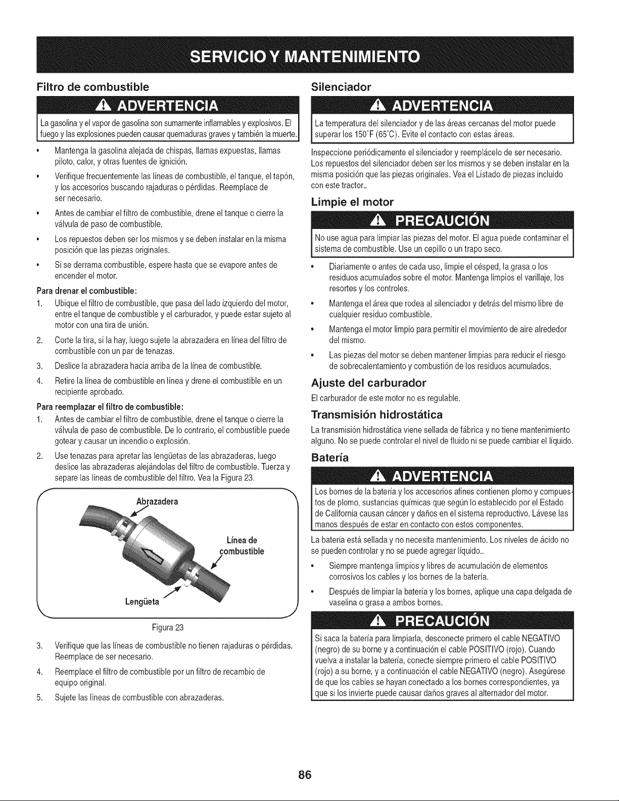
Filtro de combustible Silenciador
Lagasolinay elvaporde gasolinasonsumamenteinflamablesy explosivos.El
fuegoy lasexplosionespuedencausarquemadurasgravesy tambienlamuerte.
• Mantengala gasolinaalejadade chispas,llamasexpuestas,llamas
piloto,calor,y otrasfuentesde ignici6n.
• Verifiquefrecuentementelas I[neasde combustible,el tanque,el tap6n,
y losaccesoriosbuscandorajaduraso p@didas.Reemplacede
set necesario.
• Antesde cambiarel filtrode combustible,dreneel tanqueo cierre la
v_lvulade pasode combustible.
• Los repuestosdebenserlos mismosy se debeninstalaren la misma
posici6nquelas piezasoriginales.
• Sise derramacombustible,esperehastaquese evaporeantes de
encenderel motor.
Para drenar el combustible:
1. Ubiqueelfiltro de combustible,que pasadel ladoizquierdodel motor,
entreeltanque de combustibley el carburador,y puedeestarsujeto al
motorcon unatira de uni6n.
2. Corte latira, si lahay,luegosujetela abrazaderaen I[neadel filtro de
combustiblecon un parde tenazas.
3. Deslice laabrazaderahaciaarribade la I[neade combustible.
4. Retirela I[neadecombustibleen I[neay dreneel combustibleen un
recipienteaprobado.
Parareemplazar el filtro de combustible:
1. Antesdecambiarel filtro de combustible,dreneel tanqueo cierre la
v_lvulade pasode combustible.DeIo contrario,el combustiblepuede
goteary causar un incendioo explosi6n.
2. Use tenazas paraapretarlas lengOetasde lasabrazaderas,luego
deslice lasabrazaderasalej_ndolasdel filtro de combustible.Tuerzay
separelasI[neasde combustibledel filtro.Veala Figura23.
f
Abrazadera
Lineade
combustible
3,
4.
5.
.I
LengLieta
_.., ,J
Figura23
Verifiqueque las I[neasde combustibleno tienen rajaduraso p@didas.
Reemplacede ser necesario.
Reemplaceelfiltro decombustiblepot unfiltro de recambiode
equipooriginal.
Sujetelas I[neasde combustiblecon abrazaderas.
La temperaturadel silenciadory delas _reascercanasdel motorpuede
superarlos 150°F(65°C).Eviteel contactocon estas _reas.
Inspeccioneperi6dicamenteel silenciadory reempl_celode ser necesario.
Los repuestosdel silenciadordebenser los mismosy se debeninstalaren la
misma posici6nque las piezasoriginales.Veael Listadode piezas incluido
con este tractor..
Limpie el motor
No use agua para limpiarlaspiezasdel motor.El agua puedecontaminarel
sistemade combustible.Use un cepillo o un trapo seco.
• Diariamenteo antesde cada uso, limpie elcesped, la grasao los
residuosacumuladossobreel motor.Mantengalimpiosel varillaje,los
resortesy los controles.
• Mantengael &teaque rodeaal silenciadory detr_sdel mismolibrede
cualquierresiduocombustible.
• Mantengael motorlimpio parapermitirel movimientode airealrededor
del mismo.
• Las piezasdel motorse debenmantenerlimpiasparareducirel riesgo
de sobrecalentamientoy combusti6ndelos residuosacumulados.
Ajuste del carburador
Elcarburadorde estemotorno es regulable.
Transmisi6n hidrostatica
La transmisi6nhidrost&ticavieneselladade f_bricay notienemantenimiento
alguno.Nose puedecontrolarel nivelde fluido ni se puedecambiarel I[quido.
Bateria
Los bornesde labater[ay los accesoriosalines contienenplomoy compues
tos de plomo,sustanciasqu[micasque seg0n Ioestablecidopor el Estado
de Californiacausancancer y daSosen el sistemareproductivo.Laveselas
manos despuesdeestar encontactoconestoscomponentes.
La bater[aest&selladay no necesitamantenimiento.Los nivelesde _cido no
se puedencontrolar y no se puedeagregarI[quido..
• Siempremantengalimpiosy libres de acumulaci6nde elementos
corrosivosloscablesy los bornesde la bater[a.
• Despuesde limpiar la bater[ay los homes,apliqueuna capadelgadade
vaselinao grasa a ambos bornes.
Si saca la bater[apara limpiarla,desconecteprimeroel cable NEGATIVO
(negro) desu borney a continuaci6nel cable POSlTIVO(rojo). Cuando
vuelvaa instalarla hater[a,conecte siempreprimeroel cable POSITIVO
(rojo) a su borne,y a continuaci6nel cable NEGATIVO(negro).AsegOrese
de que los cablesse hayanconectadoa losbornescorrespondientes,ya
que si los inviertepuedecausar daSosgravesal alternadordel motor.
86
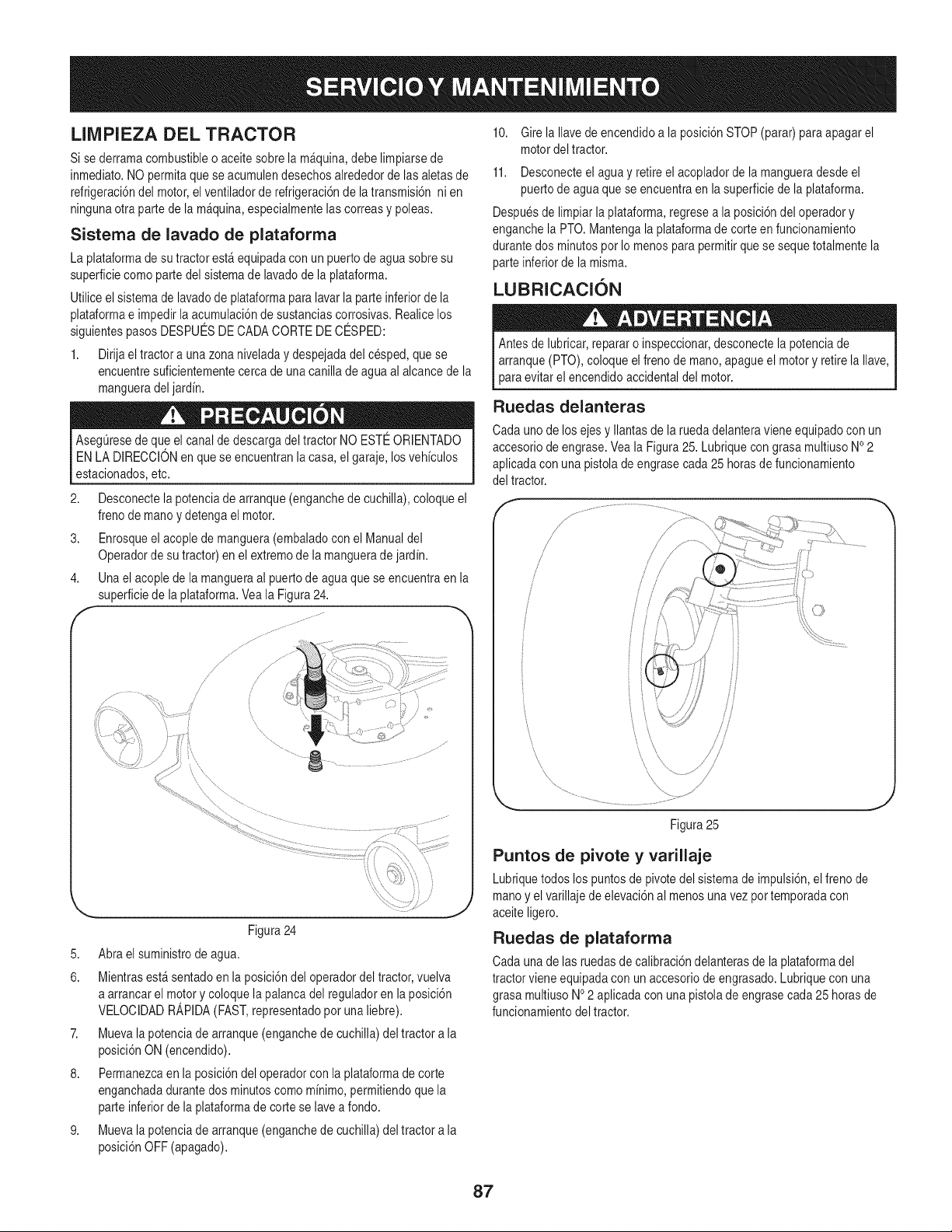
LIMPIEZA DEL TRACTOR
Si sederramacombustibleo aceitesobre la m_quina,debe limpiarsede
inmediato.NO permitaquese acumulendesechosalrededorde las aletasde
refrigeraci6ndel motor,elventiladorderefrigeraci6nde latransmisi6n ni en
ningunaotra partede la m&quina,especialmentelascorreasy poleas.
Sistema de lavado de plataforrna
La plataformade su tractorest&equipadacon un puertode aguasobre su
superficiecomo partedel sistemade lavadode la plataforma.
Utiliceel sistemade lavadode plataformapara lavarla parteinferiorde la
plataformae impedirla acumulaci6nde sustanciascorrosivas.Realicelos
siguientespasosDESPUESDECADACORTE DE CESPED:
1. Dirija el tractora unazonaniveladay despejadadel cesped, quese
encuentresuficientementecercade unacanilla de agua alalcance de la
mangueradeljardin.
AsegQresede queel canalde descargadeltractor NO ESTEORIENTADO
ENLA DIRECCIONen que seencuentran la casa,el garaje,losvehiculos
estacionados,etc.
2. Desconectela potenciadearranque (enganchede cuchilla),coloque el
frenodemano y detengael motor.
3. Enrosqueel acoplede manguera(embaladocon el Manualdel
Operadorde su tractor)en el extremode la manguerade jardin.
4. Unael acople de la mangueraal puertode agua que seencuentraenla
superficiede la plataforma.Veala Figura24.
F ............................................
Figura24
5. Abra el suministrode agua.
6. Mientrasest&sentadoen la posici6ndel operadordel tractor,vuelva
a arrancarel motory coloquela palancadel reguladoren la posici6n
VELOCIDADR_,PIDA(FAST,representadopot unaliebre).
7. Muevala potenciade arranque(enganchede cuchilla)del tractora la
posici6nON (encendido).
8. Permanezcaen la posici6ndel operadorconla plataformade corte
enganchadadurantedos minutoscomo minimo,permitiendoque la
parteinferiorde la plataformade corte se lavea fondo.
9. Muevala potenciade arranque(enganchede cuchilla)del tractora la
posici6nOFF (apagado).
10. Girela Ilavede encendidoa la posici6nSTOP(parar)paraapagar el
motordel tractor.
11. Desconecteel aguay retireel acopladorde la mangueradesde el
puertodeagua quese encuentraen la superficiede la plataforma.
Despuesde limpiarlaplataforma,regresea la posici6ndel operadory
enganchela PTO.Mantengala plataformade corte en funcionamiento
durantedos minutospot Io menos para permitirque se sequetotalmentela
parteinferiorde la misma.
LUBRICACION
Antesde lubricar,repararo inspeccionar,desconectela potenciade
arranque(PTO),coloque elfrenode mano,apagueel motory retirela Ilave,
para evitarel encendidoaccidentaldel motor.
Ruedas delanteras
Cadauno de los ejesy Ilantasde laruedadelanteravieneequipadocon un
accesoriodeengrase.Veala Figura25. Lubriquecongrasa multiusoNO2
aplicadacon unapistolade engrasecada 25 horas de funcionamiento
del tractor.
Figura25
Puntos de pivote y varillaje
Lubriquetodos los puntosde pivotedel sistemade impulsi6n,el freno de
manoy elvarillajede elevaci6nal menos unavez pot temporadacon
aceite ligero.
Ruedas de plataforma
Cadauna de las ruedasde calibraci6ndelanterasde la plataformadel
tractorviene equipadacon un accesoriode engrasado.Lubriquecon una
grasa multiusoNO2 aplicadacon una pistolade engrasecada25 horasde
funcionamientodel tractor.
87
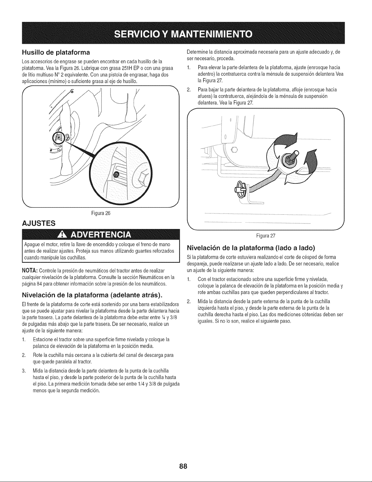
Husillo de plataforma
Los accesoriosde engrasese puedenencontraren cadahusillode la
plataforma.Veala Figura26. Lubriquecon grasa 251H EPo con unagrasa
de litio multiusoNo2 equivalente.Con una pistolade engrasar,haga dos
aplicaciones(mfnimo)o suficientegrasaal eje de husillo.
Determinela distanciaaproximadanecesariapara un ajusteadecuadoy,de
set necesario, }roceda.
1. Paraelevarla partedelanterade la plataforma,ajuste(enrosquehacia
adentro) lacontratuercacontrala mensulade suspensi6ndelanteraVea
la Figura27.
2. Parabajar la partedelanteradela plataforma,afloje (enrosquehacia
afuera)la contratuerca,alej&ndolade la mensuladesuspensi6n
delantera.Veala Figura27.
AJUSTES
Figura26
Apagueel motor,retirela Navede encendidoy coloque el freno de mano
antesde realizarajustes.Protejasus manos utilizandoguantesreforzados
cuandomanipulelascuchillas.
NOTA: Controlelapresi6nde neum_ticosdel tractorantesde realizar
cualquiernivelaci6ndela plataforma.Consultela secci6nNeum_ticosen la
pagina84 paraobtenerinformaci6nsobrela presi6nde los neum_ticos.
Nivelaci6n de la plataforma (adelante arras).
Elfrente de la plataformade corteest_ sostenidopor unabarra estabilizadora
quese puedeajustarparanivelarla plataformadesde la partedelanterahacia
la partetrasera.La partedelanterade la plataformadebe estarentre 14y 3/8
de pulgadasm&sabajoque la partetrasera. Deset necesario,realice un
ajustede la siguientemanera:
1. Estacioneeltractor sobreunasuperficiefirme niveladaycoloque la
palancade elevaci6nde la plataformaen la posici6nmedia.
2. Rote lacuchilla m&scercanaa la cubiertadel canal de descargapara
quequedeparalelaal tractor.
3. Midala distanciadesde la parte delanterade la puntade lacuchilla
hastael piso, y desdela parte posteriorde la punta de la cuchillahasta
el piso. Laprimeramedici6ntomadadebe set entre 1/4y 3/8 de pulgada
menosque la segundamedici6n.
i0
Figura27
Nivelaci6n de la plataforma (lado a lado)
Si la plataformade corteestuvierarealizandoel cortede cespedde forma
despareja,puederealizarseun ajustelado a lado.Deset necesario,realice
un ajustede la siguientemanera:
1. Con el tractorestacionadosobre unasuperficiefirme y nivelada,
coloquela palancade elevaci6nde laplataformaen la posici6nmediay
rote ambascuchillaspara quequeden perpendicularesaltractor.
2. Mida la distanciadesde la parte externade la puntade lacuchilla
izquierdahastael piso, ydesde la parteexternade la puntade la
cuchilla derechahastael piso. Lasdos medicionesobtenidasdebenset
iguales.Si no Io son,realiceel siguientepaso.
88
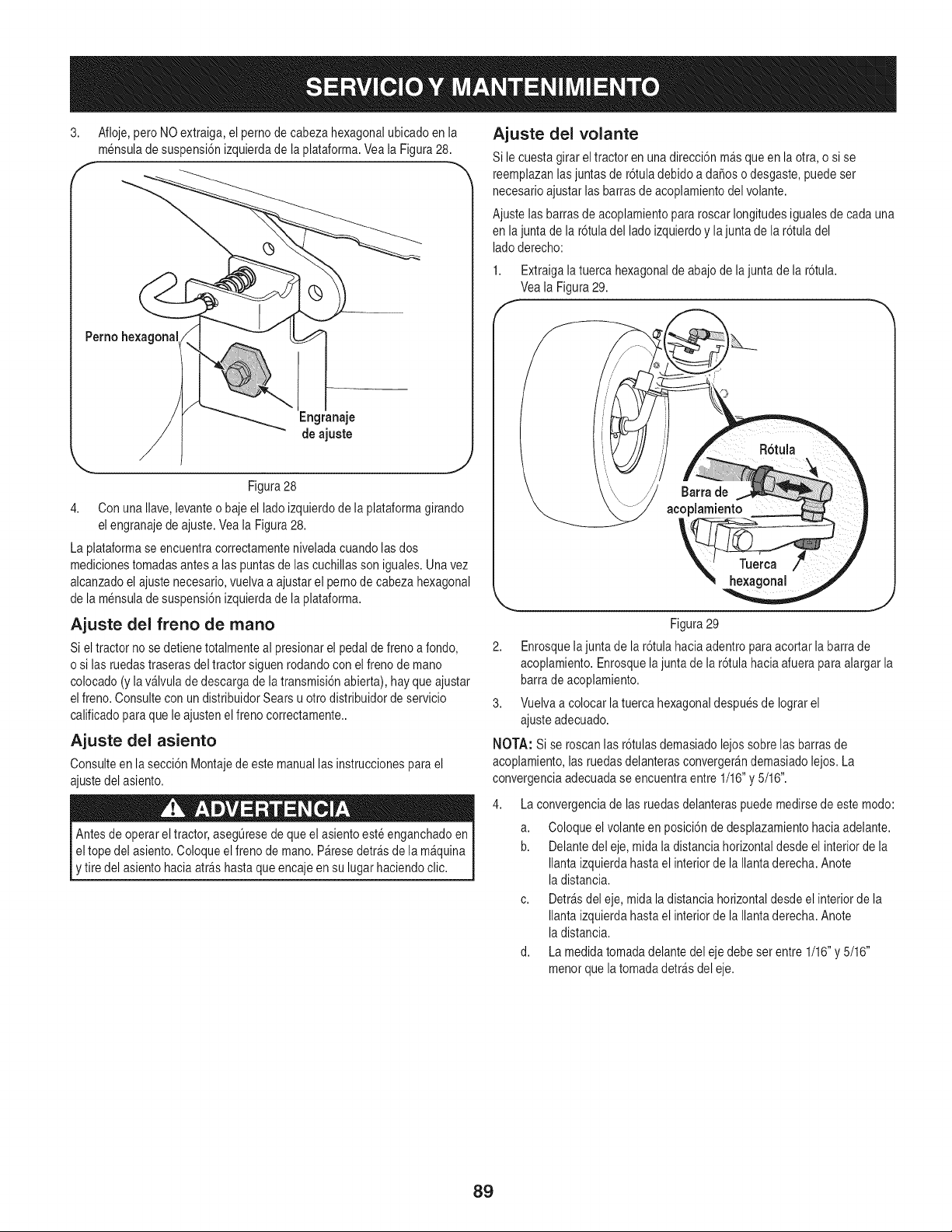
3. Afloje, pero NO extraiga,el pernode cabeza hexagonalubicadoen la
mensuladesuspensi6nizquierdade laplataforma.Yeala Figura28.
Perno he×agona
Engranaje
de ajuste
Figura28
4. Con unaIlave,levanteo baje el ladoizquierdode laplataformagirando
el engranajede ajuste.Vea la Figura28.
La plataformaseencuentracorrectamenteniveladacuandolasdos
medicionestomadasantesalas puntasde lascuchillasson iguales.Unavez
alcanzadoel ajustenecesario,vuelvaa ajustar el pernodecabeza hexagonal
de la mensulade suspensi6nizquierdade la plataforma.
Ajuste del freno de mano
Si el tractor no se detienetotalmenteal presionarel pedalde frenoa fondo,
o si lasruedastraserasdel tractor siguenrodandocon elfreno de mano
colocado(y lav&lvulade descargade latransmisi6nabierta),hay queajustar
elfreno. Consultecon un distribuidorSears u otrodistribuidorde servicio
calificadopara que le ajustenelfreno correctamente..
Ajuste del asiento
Consulteen la secci6n Montajede este manuallas instruccionespara el
ajustedel asiento.
Antes de operareltractor, asegQresede queel asiento esteenganchadoen
el tope del asiento.Coloqueel frenode mano.P&resedetr_sdela m&quina
y tire del asientohacia arrashastaque encajeen su lugar haciendoclic.
Ajuste del volante
Si le cuestagirar el tractoren unadirecci6n m&squeen laotra,o si se
reemplazanlasjuntasde r6tuladebidoa daSoso desgaste,puedeset
necesarioajustar lasbarrasde acoplamientodelvolante.
Ajustelas barrasde acoplamientopararoscarlongitudesigualesde cadauna
en lajunta de la r6tuladel ladoizquierdoy la juntade la r6tuladel
ladoderecho:
1. Extraigala tuercahexagonalde abajode lajunta de la r6tula.
Veala Figura29.
f
h
J
Figura29
2. Enrosquela juntade la r6tula haciaadentroparaacortar la barrade
acoplamiento.Enrosquela juntade la r6tulahaciaafuera paraalargar la
barradeacoplamiento.
3. Vuelvaa colocar latuercahexagonaldespuesde Iograrel
ajusteadecuado.
NOTA: Si se roscanlas r6tulasdemasiadolejossobre las barrasde
acoplamiento,las ruedasdelanterasconverger_ndemasiadolejos. La
convergenciaadecuadase encuentraentre 1/16"y 5/16".
La convergenciade las ruedasdelanteraspuedemedirsede estemodo:
a. Coloqueel volanteen posici6nde desplazamientohaciaadelante.
b. Delantedel eje, mida ladistanciahorizontaldesdeel interiorde la
Ilantaizquierdahastael interiorde la Ilantaderecha.Anote
ladistancia.
c. Detr_sdel eje, midala distanciahorizontaldesdeel interiorde la
Ilantaizquierdahastael interiorde la Ilantaderecha.Anote
ladistancia.
d. La medidatomadadelantedel eje debe set entre 1/16"y 5/16"
menorquela tomadadetr_sdel eje.
89
PREPARACI6N DEL MOTOR
IMPORTANTE: Icombustiblequequedaen el tanquecuandohacecalor se
deterioray causaproblemasgravesde encendido.
Nuncaalmacenelatractor corta cespedcon combustibleen el tanque
en unespaciocerradoo en _reaspocoventiladasdondelos gasesdel
combustiblepuedanIlegara unallamaexpuesta,unachispao un piloto
como el quetienen algunoshornos,calentadoresde agua,secadoresde
ropao algOnartefactoa gas.
PREPARAClON DEL TRACTOR CORTA
CESPED
Paraevitar quese formendep6sitosde goma dentrodel carburadordel motor
y posiblesdesperfectosen el motor,elsistemade combustibledebe set
vaciadocompletamente,o se debetratar lagasolinacon un estabilizadorpara
evitarel deterioro.
Si utilizaunestabilizadorde combustible:
a. Lea las instruccionesy recomendacionesdel fabricante
del producto.
b. Agreguela cantidadcorrectade estabilizadorparalacapacidad
del sistemade combustiblea gasolinalimpiay nueva.
c. Lleneel tanquecon combustibletratado y hagafuncionarel motor
2-3 minutospara estabilizarel combustibledentrodel carburador.
Cuandovacfeel sistemade combustible:
a. No drene el combustiblecuandoel motorest_ caliente.Permita
queel motorse enfrfebien. Dreneel combustibledentrode un
recipienteaprobadoy al aire libre,lejosde cualquier
llamaexpuesta.
b. Dreneun granvolumende combustibledel tanque,desconectando
la Ifneadecombustibledel filtro de combustibleen Ifneaquese
encuentracerca del motor.VeaParadrenar el combustibleen la
pagina86.
La gasolina essumamenteinflamabley puedeset explosivaen ciertas
condiciones.Vacfelaantes de almacenarel equipo duranteperfodos
prolongados.Dreneel combustibleOnicamentedentrode un recipiente
aprobadoy alaire libre,lejos de cualquierllama expuesta.Dejeque el mo-
tor se enfrfe.Antesde drenar el combustible,apaguecigarrillos,cigarros,
pipasy otrasfuentesde combusti6n.Almacenelagasolinaen un recipiente
aprobado,en un lugarseguro.
c. Vuelvaa conectarla Ifneade combustibley hagafuncionar el
motorhastaque comiencea fallar, useentoncesel cebadorpara
mantenerel motoren marchahastaagotartodo el combustible
del carburador.
d. Desconectela Ifneadecombustibley drenela gasolinaque queda
en el sistema.
Limpiey lubriqueperfectamenteeltractor comose describeenlas
instruccionesde lubricaci6n.
No utiliceuna lavadoraa presi6no manguerade jardfn para limpiarsu
unidad.
Almacenela unidadenunazona limpiay seca. No la almacenecerca de
productoscorrosivoscomo potejemplofertilizantes.
La gasolinaes unasustanciat6xica. Eliminela gasolinaadecuadamente.
Comunfquesecon lasautoridadeslocalesparaaveriguarcuries son los
metodosadecuadospara eliminarla gasolina.
Extraigala bujfay vierta una (1)onza de aceitepara motorpor el orificio de
la bujfahaciael interiordel cilindro.Haga girar el motorvariasveces para
distribuirel aceite.Vuelvaa colocar la bujfa.
9O
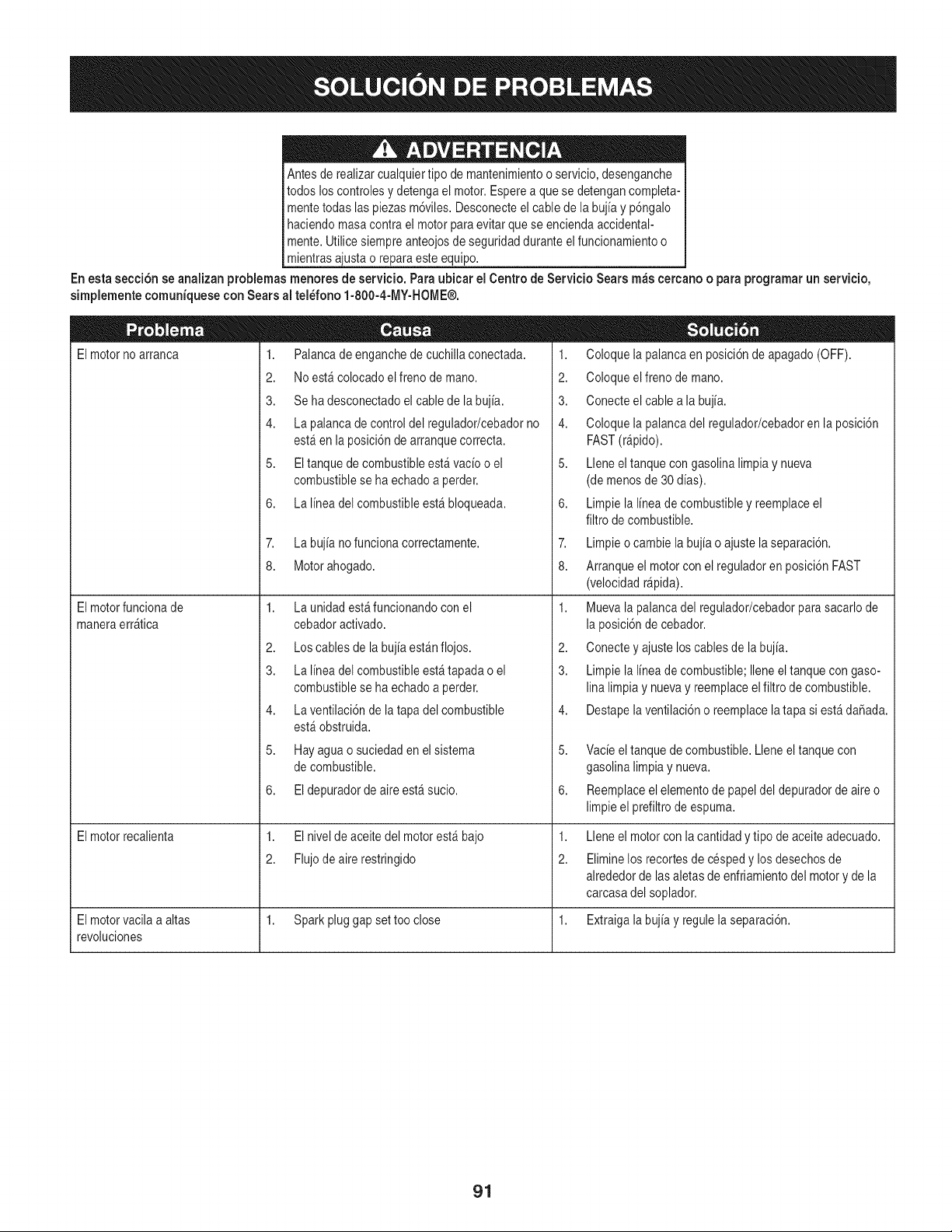
Antesde realizarcualquiertipo de mantenimientoo servicio,desenganche
todos loscontrolesy detengael motor.Esperea que se detengancompleta-
mentetodas laspiezasm6viles.Desconecteel cable de la bujia y p6ngalo
haciendomasacontrael motorparaevitarque se enciendaaccidental-
mente.Utilice siempreanteojosde seguridadduranteelfuncionamientoo
mientrasajustao reparaesteequipo.
En esta secci6n se analizan problemas menores de servicio. Para ubicar el Centro de Servicio Sears m_s eercano o paraprogramarun servicio,
simplementeeomuniquesecon Searsal tel_fono 1-800-4-MY-HOME®.
El motor no arranca 1. Palanca de enganche de cuchilla conectada.
2. No estfi colocado el freno de mano.
3. Se ha desconectado el cable de la bujia.
4. La palanca de control del regulador/cebador no
estfi en laposicidndearranquecorrect&
5. El tanquede combustibleestHvacio o el
combustiblese ha echadoa perder.
6. La linea del combustibleestHbloqueada.
El motorfuncionade
maneraerrHtica
El motorrecalienta
7. Labujia no funcionacorrectamente.
8. Motorahogado.
1,
2.
3.
4.
5.
6.
Launidad estHfuncionandocon el
cebadoractivado.
Los cables de la bujia estHnflojos.
La linea del combustibleestHtapadao el
combustiblese ha echadoa perder.
La ventilaci6nde la tapadel combustible
estHobstruida.
Hayaguao suciedaden el sistema
de combustible.
Eldepuradorde aireestHsucio.
1. El nivelde aceitedel motorestHbajo
2. Flujodeairerestringido
1. Coloquela palancaen posici6nde apagado(OFF).
2. Coloqueelfreno de mano.
3. Conecteelcable a la bujia.
4. Coloquela palancadel regulador/cebadoren la posici6n
FAST(rHpido).
5. Lleneel tanquecon gasolinalimpia y nueva
(de menosde 30 dias).
6. Limpiela linea de combustibley reemplaceel
filtro de combustible.
7. Limpieo cambiela bujia o ajustela separaci6n.
8. Arranqueel motorcon el reguladoren posici6nFAST
(velocidadrHpida).
1. Muevala palancadel regulador/cebadorparasacarlode
la posici6nde cebador.
2. Conecteyajuste loscablesde la bujia.
3. Limpiela linea de combustible;Ileneeltanque con gaso-
linalimpia y nuevay reemplaceelfiltro de combustible.
4. Destapelaventilaci6no reemplacelatapa si estHda_ada.
5. Vacieel tanquedecombustible.Lleneel tanquecon
gasolinalimpiay nueva.
6. Reemplaceelelementode papeldel depuradorde aireo
limpieel prefiltrode espuma.
1,
2.
Lleneel motorcon la cantidady tipode aceiteadecuado.
Eliminelos recortesde cespedy losdesechosde
alrededorde lasaletasde enfriamientodel motory de la
carcasadel soplador.
El motorvacila a altas 1. Sparkpluggap set too close 1. Extraigalabujia y regulela separaci6n.
revoluciones
91
Elmotorfuncionarealen
marchalenta
Vibraci6nexcesiva
La cortadorade c_spedno
procesalos recortescomoabono
Cortedesigual
1,
2.
1.
2.
1.
La bujia de encendidoesta sucia
Eldepuradorde aireest,. sucio
Las cuchillasde corte estanflojas o
desbalanceadas
La cuchillade corteesta da_ada,
desafiladao doblada
La velocidaddel motores demasiadolenta.
2. Pastomojado.
3. C_speddemasiadoalto.
4. Cuchilladesafilada.
1. La @ataformano estacorrectamentenivelada.
2. Cuchilladesafilada.
3. Presi6nde neumaticosdesigual.
1. Extraigala bujiay regulela separaci6n.
2. Reem@aceelelementodepuradorde airey/o limpie
el prefiltro.
1. Apriete lacuchillay el husillo.Estabilicela cuchilla.
2. Reemplacelacuchilla.
1. Coloque el controldel estrang@ador/cebadorenla
posici6nFAST(velocidadrapida,representadapot
unaliebre).
2. Noproceseabonocuandoel pastoestamojado.
3. Corte unavez con altura decorte elevaday luegovuelva
a cortarel c_speda la alturadeseada,o hagauna pasada
de corte mas angosta.
4. Afile ocambie lacuchilla.
1. Haga un ajustede la plataformade ladoa lado.
2. Afile ocambie lacuchilla.
3. Verifiquela presi6nde los cuatroneumaticos.
&NECESITAMASAYUDA?
:b3ncontrarAla respues tay _as en managemyhomeoco_ o i sin cargo!
o Este y los manua]esde todos sus otros productoslos encontraP8en ]inea.
ii ° SuspPeguntasserSnPespondidaspopnuestro equtpode especia]tstas.
il ° 0btengaun plan de mantenimientopersona]izadopapasu hogaP.
o Encuentreinformact6ny herPamtentasque]o ayudaP_ncon los proyectosdom_sttcos.
manage _ home
presentadopor Sears
...._!@i!iii!iii!iii!iii!iii!iii!iii!iii!iii!iii!iii!iii!iii!iii!iii!iii!iii!iii!iii!iii!iii!iii!iii!iii!iii!iii!iii!iii!iii!iii!iii!iii!iii!iii!iii!iii!iii!iii!iii!iii!iii!iii!iii!iii!iii!iii!iii!iii!iii!iii!iii!iii!iii!iii!iii!iii!iii!iii!iii!iii!iii!iii!iii!iii!iii!iii!iii!iii!iii!iii!iii!iii!iii!iii!iii!iii!iii!iii!iii!iii!iii!iii!iii!iii!iii!iii!iii!iii!iii!iii!iii!iii!iii!iii!iii!iii!iii!iii!iii!iii!iii!iii!iii!iii!iii!iii!iii!iii!iii!iii!iii!iii!iii!iii!iii!iii!iii!iii!iii!iii!iii!iii!iii!iii!iii!iii!iii!iii!iii!iii!iii!iii!iii!iii!iii!iii!iii!iii!iii!iii!iii!iii!iii
92
Felicitacionespor haberrealizadounaadquisici6ninteligente.El
productoCraftsman@queha adquiridoest_ dise_adoy fabricado
parabrindarrnuchosa_osde funcionarnientoconfiable.Perocorno
todoslos productosa vecespuederequerirde reparaciones.Esen
esernornentocuandoel disponerde unAcuerdode protecci6npara
reparacionesle puedeahorrardineroy problernas.
A continuaci6nsedetallanlos puntosincluidosen el Acuerdo:
• Servicio experto prestadopornuestros10,000especialistasen
reparacionesprofesionales
• Servicio ilirnitadosincargoparalaspiezasy la rnanode obraen
todaslas reparacionescubiertas
• Reernplazodel productohasta1500d61aressi no es posible
repararel productocubierto
• Descuentode 10%del precionormaldel servicioy delas piezas
relacionadascon el rnisrnoqueno est_ncubiertasporel acuerdo;
adern&s,10%del precionormalde laverificaci6nde rnantenirniento
preventivo
• Ayudar_pidapottel_fono- IoIlarnarnosResoluci6nR_pida- el
apoyotelef6nicode unCharnuscaal representante.Pienseen
nosotroscornoel manual"de undue_ohablador."
Unavezadquiridoel Acuerdo,puedeprograrnarel serviciocon
tan s61orealizarunaIlarnadatelef6nica.PuedeIlarnarencualquier
mornentodeldia o dela nocheo prograrnarun servicioen linea.
ElAcuerdode Protecci6nde Reparaci6nes unacornprasin riesgo.
Siustedanulaporalguna raz6nduranteel periodode garantiade
producto,proporcionarernosun reernbolsoIleno.O,un reernbolso
prorrateadoencualquiermornentodespu_sdelperiodode garantia
de productoexpira,iAdquieraboysu acuerdode protecci6npara
reparaciones!
Seaplican deterrninadaslirnitaciones y exclusiones.Paraobtener
inforrnaci6nadicional y preciosen los Estados UnidosIlarne al
1-800-827-6655.
El*Coverage en Canad_variaen algunosarticulos. Paradetalles
Ilenosla IlarnadaCharnuscaCanad_en 1-800-361-6665.
Servicio de instalaci6nde Sears
Sideseasolicitarla instalaci6nprofesionalde Searsde aparatos
dorn_sticos,dispositivosparaabrir portones,calentadoresde agua
y otrosarficulosdorn_sticosirnportantes,en los EstadosUnidoso
Canad_Ilarneal 1-800-4-MY-HOME®.
93
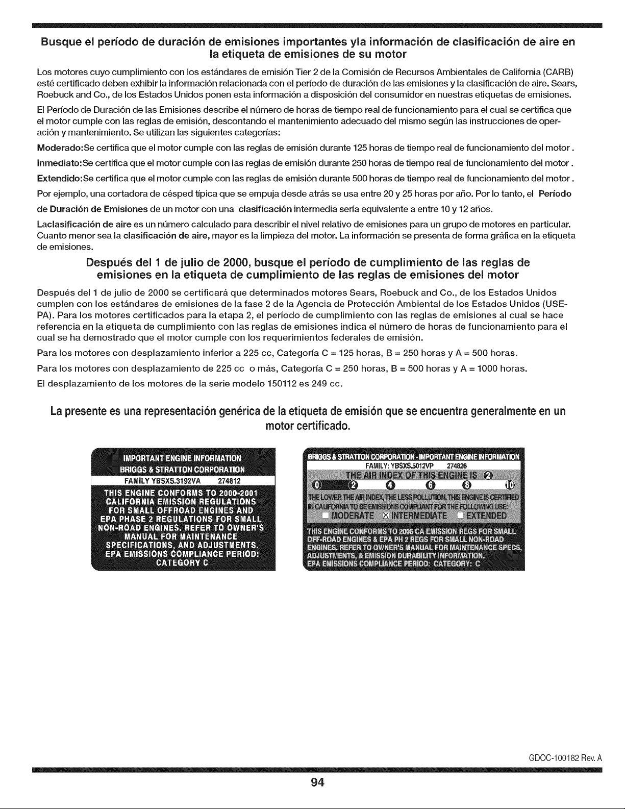
Busque el periodo de duraci6n de emisiones importantes yla informaci6n de clasificaci6n de aire en
la etiqueta de emisiones de su motor
Los motores cuyo cumpiimiento con los estAndares de emisi6n Tier 2 de la Comisi6n de Recursos Ambientales de California (CARB)
est6 certificado deben exhibir la informaci6n relacionada con el perJodo de duraci6n de las emisiones y la clasificaci6n de aire. Sears,
Roebuck and Co., de los Estados Unidos ponen esta informaci6n a disposici6n deJ consumidor en nuestras etiquetas de emisiones.
El Periodo de Duraci6n de las Emisiones describe el nQmero de horas de tiempo real de funcionamiento para el cual se certifica que
el motor cumple con las reglas de emisi6n, descontando el mantenimiento adecuado deJ mismo segQn las instrucciones de oper-
aci6n y mantenimiento. Se utilizan las siguientes categorias:
Moderado:Se certifica que el motor cumpie con las reglas de emisi6n durante 125 horas de tiempo real de funcionamiento deJ motor.
Inmediato:Se certifica que el motor cumple con las reglas de emisi6n durante 250 horas de tiempo real de funcionamiento deJ motor.
Extendido:Se certifica que el motor cumple con las reglas de emisi6n durante 500 horas de tiempo real de funcionamiento deJ motor.
Por ejemplo, una cortadora de c6sped tJpica que se empuja desde atrAs se usa entre 20 y 25 horas por afio. Por Io tanto, el Periodo
de Duraci6n de Emisiones de un motor con una clasificaci6n intermedia seria equivalente a entre 10 y 12 afios.
Laclasificaci6n de aJre es un nQmero calculado para describir eJnivel reiativo de emisiones para un grupo de motores en particular.
Cuanto menor sea Jaclasificaci6n de aire, mayor es JaJimpieza deJ motor. La informaci6n se presenta de forma gr&fica en Jaetiqueta
de emisiones.
Despu_s del 1 de julio de 2000, busque el periodo de cumplimiento de las reglas de
emisiones en la etiqueta de cumplimiento de las reglas de emisiones del motor
Despu_s deJ 1 de julio de 2000 se certificar_, que determinados motores Sears, Roebuck and Co., de los Estados Unidos
cumpien con los estAndares de emisiones de la fase 2 de la Agencia de Protecci6n Ambiental de los Estados Unidos (USE-
PA). Para los motores certificados para la etapa 2, el periodo de cumpiimiento con las reglas de emisiones al cual se hace
referencia en la etiqueta de cumpiimiento con las reglas de emisiones indica el nQmero de horas de funcionamiento para el
cuaJ se ha demostrado que el motor cumpie con los requerimientos federales de emisi6n.
Para los motores con desplazamiento inferior a 225 cc, Categoria C = 125 horas, B = 250 horas y A = 500 horas.
Para los motores con desplazamiento de 225 cc o mAs, Categoria C = 250 horas, B = 500 horas y A = 1000 horas.
El despiazamiento de los motores de la serie modelo 150112 es 249 cc.
La presente es una representaci6n gen_rica de la etiqueta de emisi6n que se encuentra generaimente en un
motor certificado.
FAMILYYBSXS.3192VA 274812
GDOC-100182Rev.A
94
(Esta p_.gina se aplica s61oen EE.UU. y Canada.).
Sears, Roebuck and Co., U.S.A. (Sears), el Consejo de Recursos Arnbientales de California (CARB)
y la Agencia de Protecci6n Arnbiental de los Estados Unidos (EPA)
Declaraci6n de garantia del sistema de control de emisiones (derechos y obligaciones de la garantia de defectos del propi=
etario)
LA COBERTURADE LA GARANTJADE CONTROLDEEMISIONESES Y PARALOSMODELOSCERTIFICADOSDELANO 1997YPOSTERIORES,
APLIOABLEA LOS MOTORESCERTIFICADOSCOMPRADOSENCALIFOR- QUESE COMPRENY UTILICENENCUALQUIERPARTEDE LOSESTADOS
NIA EN1995Y POSTERIORMENTE,QUESE UTILIZANENCALIFORNIA, UNIDOS(Y A PARTIRDEL 1 DE ENERODE2001 ENCANADA).
Declaraci6n de garanfia sobre defectos en el control de ernJsiones para California y los Estados UnJdos
ElConsejode RecursosAmbientalesde California(CARB),la EPA(Agencia
de Protecci6nAmbientalde los EE.UU.)y Searstienenel gusto de explicarla
garantiadel sistemadecontrolde emisionespara motoresdela_o 2000y para
elfuturo con relaci6na motorespeque_ostodo terreno(SORE).En California,
los nuevosmotorespeque_ostodo terrenodebenestar dise_ados,construidos
y equipadosparacumplircon las rigurosasnormasanti-smogdelestado.En
el restodelos EstadosUnidos,losmotoresnuevostodoterrenode encendido
porchispacertificadosparael a_o 1997debencumplirest_ndaressimilares
establecidospot la EPA.Sears debegarantizarel sistemadecontrol de emi-
sionesde su motorpara losperiodosdetiempoenumeradosa continuaci6n,
siemprequeno hayaabuso,negligenciao mantenimientoindebidode su
motortodoterrenopeque_o.Su sistemade controldeemisionespuedeincluir
piezastalescomoel carburador,el filtro de aire, elsistemade encendido,el
silenciadoryel conversorcatalitico.Tambienpuedeincluirconectoresy otras
unidadesrelacionadascon lasemisiones.Dondeexistaunacondici6ncubierta
por la garantia,Searsreparar_su peque6omotortodo terrenosin costoalguno
incluyendodiagn6stico,piezasy manodeobra
Cobertura de la garantJa Sears para defectos en el control de ernJsiones
Los motorestodo terrenopeque6osest_ngarantizadosen Io relativoalcontrol alas disposicionesque se indiquena continuaci6n.Si una parte de su motor
de emisionesparadefectosen piezasduranteun per[odode dos a_os,sujeto cubiertapot lagaranfiaes defectuosa,Sears reparar_o sustituir_dichaparte.
Responsabilidades del propietario en relacibn con la garantia
Comopropietariodel motortodo terrenopeque_o,Ud.es responsablede la
realizaci6ndel mantenimientorequeridoquese incluyeen las instrucciones
de operaci6ny mantenimiento.Searsrecomiendaquese conserventodoslos
recibosrelativosal mantenimientode su motortodoterrenopeque_o,pero
no pude denegarla garantiasimplementepor la faltade los mismos,o por su
incumplimientodel mantenimientoprogramatic.Comopropietariodel motor
peque_otodoterrenodebe saberque, sinembargo,Sears lepuede negar
lacoberturade lagarantiasi su motortodoterrenopeque6oouna piezadel
mismohanfalladodebidoa abuso,negligencia,mantenimientoindebidoo
a modificacionesno aprobadas.Ud.es responsablede presentarsu motor
todoterrenopeque6oa un distribuidorde serviciosSearsautorizadotan pronto
comoaparezcaun problema.Las reparacionesde la garantiasinconflicto
debencompletarseen un plazode tiemporazonable,no superiora 30 dias.Si
tienealguna preguntarespectoa sus derechosy responsabilidadesreferentes
a lagarantia,debe contactarcon un representantede serviciosSears al 1--
800--469--4663.La garantiade emisioneses unagarantiapordefectos.Los
defectosse juzgandeacuerdocon elfuncionamientonormalde un motor.La
garantiano est_relacionadacon unapruebade emisionesen uso.
Disposiciones de la garantJa Sears para defectos en el control de emJsiones
Las siguientesson disposicionesespecificasrelacionadascon la coberturade lagarantia paradefectosen el controlde emisiones.Esun a_adidoa lagarantiade
motorSearspara motoresnoreguladosque seencuentraen lasinstruccionesde funcionamientoy mantenimiento.
1. Piezascon garantia
La coberturade esta garantiase extiendeL]nicamentealas piezas
queaparecena continuaci6n(las partesde lossistemasde controlde
emisiones),siempreque dichaspiezasestuvieranya en el motoren el
momentode su compra.
a. Sistemademedici6n de combustible
• Sistemade enriquecimientopara arranqueenfrio
• Carburadory partesinternas
• Bombade combustible
b. Sistemadeinducci6nde aire
• Filtrode aire
• Colector de admisi6n
c. Sistemadeencendido
• Bujia(s)de encendido
• Sistemade encendidomagneto
d. Sistemadelcatalizador
• Convertidorcatalitico
• Colector de escape
• Sistemade inyecci6nde aireo v_lvulade impulsos
e. Elementosvariadosusadosenlos sistemasanteriores
• Wlvulas de vacio,sensiblesa temperatura,posici6ny tiempo
e interruptores
• Conectoresy montajes
2. AIcancede la cobertura
Searsgarantizaal poseedorinicialy a loscompradoressubsiguientes
quelas piezascon garantiano tendr_ndefectosen materialesni mano
de obra que provoquenla falla de las mismasduranteun periodode
dos aSosa partirde la fechaen queel motorse entregaa un comprador
particular.
3. Sin cargo
La reparaci6no reemplazode cualquierpartecon garantiase realizar_
sin cargo alguno parael poseedor,incluyendotareasde diagn6sticoque
permitandeterminarsi una partecongarantiaes defectuosa,siempreque
dichodiagn6sticose realiceen undistribuidorde servicios Searsautoriza-
do. Parael servicio de lagarantia de emisiones,contacteal distribuidorde
serviciosSearsautorizadom_s cercanoincluidoen las"P_ginasamarillas"
en lascategorias"Motores,gasolina","Motoresdegasolina","Podadoras
de cesped",o similares.
4. Reclamacionesy exclusionesa la cobertura
Las reclamacionesde lagarantia debenenviarsede acuerdocon las
disposicionesde la politica de garantiaparamotoresSears. La cobertura
de lagarantia excluir_defectosen piezascon garantia queno sean partes
originalesSears,o abuso,negligenciao mantenimientoincorrecto,tal y
como se estableceen lapolitica degarantia para motoresSears.Sears no
es responsablede lasfallas en piezascongarantia provocadaspor el uso
de partesa_adidas,que no seanoriginaleso quese hayan modificado.
5. Mantenimiento
Cualquierpartecon garantiaque no esteprogramadapara set reempla-
zadacomo mantenimientorequerido,o que s61odeba inspeccionarse
regularmentealefecto de "inspeccioneo reemplacesegL]nsea necesario",
estar_garantizadacontradefectosduranteel periodode la garantia.Todas
las piezasgarantizadasqueesten programadasparasu reemplazopara
cumplir conlos requisitosde mantenimientoestar_ngarantizadass61o
por el periodoanterioral primerreemplazoprogramaticparadicha pieza.
Cualquierpiezade recambioquesea equivalenteen funcionamientoy
durabilidadpuedeusarse para realizarmantenimientoo reparaciones.El
propietarioes responsablederealizartodoel mantenimientorequerido,tal
y comose define en las instruccionesdefuncionamientoy mantenimiento
Sears
6. Coberturaindirecta
Porla presente,la coberturase extiendea la falla de cualquiercomponente
de motorprovocadapot lafalla de unapiezacon garantiaque este todavia
en periodode garantia.
En los EstadosUnidosy Canad_hay unalineade atenci6nde 24 horas,1-800-469--4GG3,quecuentacon unmenL]con mensajespre-grabadosque contienen
informaci6npara el mantenimientode motores.
DECLARACIONFEDERALy/oDECALIFORNIASOBRE GARANTJAS EN EL CONTROL DE EIVIISIONES
SUS DERECHOS Y OBLIGACIONES EN CUANTO A LA GARANTJA
MTDConsumerGroupInc, la Agencia de Protecci6nMedioambientaldelos EstadosUnidos(EPA),y paraaquellosproductoscertificadosparasu ventaen el es-
tadode California,el Departamentode los Recursosdel Aire de California(CARB)secomplacenen explicarla garanfiaque cubre al sistemade control(ECS)de
emisiones(evaporativasy/o de escape)de su equipoy motor(motorde equipos de exteriores)de encendidopot chispa paratodo terreno,peque_o,deexteriores
del a_o2006 y a_osposterioresEn California,losnuevosmotoresde equipos de exterioresdebenestar dise_ados,construidosyequipadospara cumplircon las
estrictasnormasantipoluci6ndel Estado(en otrosestados,losequipos del a_o 1997y modelosposterioresdebenserestar dise_ados,construidosy equipados
para cumplirconlas regulacionesde motoresdeencendidopor chispa para todoterrenopeque_osde laAgencia de Protecci6nMedioambientalde los Estados
Unidos,(EPA).MTDConsumerGroupInc.debe garantizarel sistemade controlde emisiones(ECS) de su motordeequipos de exteriorespot el periodode
tiempo indicadom_sabajo,siempreycuando no existauso incorrecto,negligenciao mantenimientoinadecuadodedicho motor.
Su ECSpuedeincluir piezastalescomo el carburador,el sistemade inyecci6nde combustible,el sistemade encendido,el convertidorcatalitico,losdep6sitos
de combustible,laslineas de combustible,lostaponesde combustible,lasv_lvulas,contenedores,filtros, manguerasde vapor,abrazaderas,conectoresyotros
componentesafinesrelacionadosconlasemisiones.
Dondeexista unacondici6ncubiertapor la garantia,MTDConsumerGroupInc. reparar_su motorde equiposde exterioressincosto alguno incluyendoel
diagn6stico,las piezasy la mano de obra.
COBERTURA DE LA GARANTJA DEL FABRICANTE:
Este sistemade control de emisionesse garantizaporel t@minode dos aSos.Si alguna piezarelacionadacon lasemisionesde su motorde equiposde
exterioreses defectuosa,MTDCONSUMERGROUPINC.reparar_o sustituir_dicha pieza.
RESPONSABILIDADES DEL PROPIETARIO SEGUN LA GARANTJA:
En su car_cterde propietariodel motorde equipos de exteriores,usted es responsabledel mantenimientorequeridoquese especificaen el manualdel propieta-
rio.MTDConsumerGroup Inc le recomiendaque conservetodos losrecibos quecubrenel mantenimientode su motor,no obstanteIo cual MTDConsumerGroup
Inc no podr_denegarel cumplimientode lagarantia Qnicamentepor lafaltade los recibos.
Comopropietariodel motorde equiposde exteriores,usteddebe saber queMTDConsumerGroupInc. puededenegarlacoberturade lagarantia si su motoro
unapieza del mismofallandebidoa uso incorrecto,negligencia,mantenimientoindebidoo a modificacionesno aprobadas.
Ustedes responsablede presentarsu motoral centrode distribuci6no serviciotecnico de MTDConsumerGroupInc.tan prontocomo aparezcael problema.Las
reparacionescubiertaspor la garantiase debenIlevara caboen un lapso razonableque no excedade 30 dias. Si tiene alguna preguntarespectode lacobertura
de la garantia,p6ngaseen contactocon el Departamentodel ServicioT@nicode MTDConsumerGroupInc.al telefono1-800-800-7310o pot correoelectr6nico
en http://support.mtdproducts.com
COBERTURA DE LA GARANTJA DE EMISIONES GENERALES:
MTDConsumerGroupIncgarantizaal compradorfinal y a cadacompradorsubsiguienteque el motorde equiposde exteriores:est_ dise_ado,construidoy
equipadode mododecumplir contodas las regulacionesaplicablesy quese encuentralibrede defectosde materialesyde fabricaci6nque pudierencausarla
falla de una piezagarantizadaidentica,en todos losaspectosmaterialesa la pieza descriptaen la solicitudde certificaci6ndeMTDConsumerGroup Inc.
El periodode garantiacomienzaen la fechade entregadel motoral compradorfinal o en lafecha en que la m_quinase pone en funcionamientopot primeravez.
El periodode garantiaes de dosaSos.
Sujetoa ciertas condicionesyexclusionesquese indicana continuaci6n,lagarantia delas piezas relacionadascon lasemisioneses la siguiente:
1. Cualquierpiezagarantizadaque no esteprogramadaparaser reemplazadacomo partedel mantenimientorequeridoen lasinstruccionesescritassuminis-
tradasse garantizaporel periodo de garantiaarriba mencionado.Sila pieza falla duranteel periodo de coberturade lagarantia, la mismaser_reparada
o reemplazadapor MTDConsumerGroupInc. de acuerdo con el parrafo(4) a continuaci6n.Cualquierpiezareparadao reemplazadasegQnlagaranfia se
garantizar_potel resto del periodode garantia.
2. Cualquierpiezagarantizadaqueeste programadasolamentepara inspecci6nregularen las instruccionesescritassuministradassegarantiza potel periodo
de garantia arribamencionado.Cualquierpiezareparadao reemplazadasegQnla garantiase garantizar_pot el restodel periodo.
3. Cualquierpiezagarantizadaqueeste programadapara reemplazosegQnel mantenimientorequeridode conformidadcon lasinstruccionesescritassuminis-
tradas,se garantizaporel periodode tiempo anteriora laprimerafecha de reemplazoprogramadapara esapieza.Si la piezafalla antes del primerreemplazo
programado,la mismaser_ reparadao reemplazadapot MTDConsumerGroupInc.de acuerdo con el parrafo(4) a continuaci6n.Cualquierpiezareparadao
reemplazadabajogarantia se garantizar_potel resto del periodoanterioral primerreemplazoprogramaticpuntualpara esapieza.
4. La reparaci6no el reemplazodecualquierpiezagarantizadade conformidadcon lasdisposicionesde lagarantiaqueaqui se estipulase deben realizaren un
centrodegarantiasin costo alguno para el propietario.
5. Noobstantelas disposicionesque aquise estipulan,losservicios o reparacionesbajo garantiase suministrar_nen todos nuestroscentrosdedistribuci6nbajo
franquiciademantenimientopara los motoreso equiposen cuesti6n.
6. El propietariodel motorde equiposde exterioresno deber_pagarel trabajode diagn6sticodirectamenteasociadocon unapiezagarantizadadefectuosaen
relaci6ncon las emisiones,siemprey cuandodichotrabajode diagn6sticose realiceen un centrocubiertopot la garantia.
7. MTDConsumerGroupInces responsablepotda6os causadosa otros componentesde motoreso equiposderivadosde lafalla bajo garantiade cualquier
piezagarantizada.
8. Durantelatotalidaddelperiododegarantiadelmotoryequipoparatodoterrenoarribamencionado,MTDConsumerGroupIncmantendr_unsuministro
depiezasbajogarantiasuficienteparasatisfacerlademandaesperadadetalespiezas.
9. Cualquierpiezadereemplazosepodr_usarparaelcumplimientodelmantenimientoolasreparacionesbajogarantiaysesuministrar_nsincargopara
elpropietario.Dichousonoreducir_lasobligacionesdegarantiadeMTDConsumerGroupInc.
10.Nosepodr_nusarpiezasadicionalesnimodificadasquenoestenexentasdeacuerdoconelDepartamentodelosRecursosdelAire(AirResourcesBoard).
Elusodecualquierpiezaadicionalomodificadanoexentaporelcompradorfinalser_causaldeinvalidezdelosreclamosbajogaranfia.MTDConsumer
GroupIncnotendr_responsabilidadpotlagarantiadefallasdepiezasgarantizadasquefuerencausadaspotelusodeunapiezaadicionalnoexenta
omodificada.
PIEZAS GARANTIZADAS:
La reparaci6no el reemplazodecualquierpiezagarantizadaquede otto modo pudieseestar cubiertapot lagarantia podr_set excluidadetal coberturade
garantiasi MTDConsumerGroupIncdemuestraqueel motores objeto deuso incorrecto,negligenciao mantenimientoinadecuado,y que tal uso incorrecto,
negligenciao mantenimientoinadecuadofue causadirectade la necesidadde reparaci6no reemplazode dichapieza.NoobstanteIo antedicho,cualquierajuste
de un componenteconun dispositivode limitaci6nde ajusteinstaladoen f_brica y quefuncioneadecuadamente,podr_set cubiertopot la garantia.Adem_s,
la coberturabajoesta garantiase extiendesolo a piezasqueestuvieronpresentesen el motory equipotodo terrenoadquiridos.
Est_ncubiertaslas siguientespiezascon garanfiaparaemisiones(decorresponder):
(1) Sistemade medici6nde combustible
• Sistemade mejorapara inicioen frio (cebadosuave)
• Carburadory piezas internas(o sistemade inyecci6npotcombustible)
• Bombade combustible
• Dep6sitode combustible
(2) Sistemade inducci6nde aire
• Purificadordeaire
• Colectordeadmisi6n
(3) Sistemade encendido
• Bujia(s) deencendido
• Sistemade encendidopot magneto
(4) Sistemade encendido
• Convertidorcatalitico
• SAl(v_lvula Reed)
(5) Componentesvariosutilizadosen el sistemaanterior
• Wlvulas e interruptoresde vacio,temperatura,posici6nsensiblesal tiempo
• Conectoresy montajes
(6) Controlevaporativo
• Manguerade combustible
• Abrazaderasde la manguerade combustible
• Tap6ndel combustibleatadopot correa
• Cajadecarbono
• Lineas de vapor
GDOC-100223

98

99

Riding Equipment
questions or problems?
Satisfaction with your purchase
is our number one concern!
To troubleshoot problems,
get answers to questions, order parts,
or schedule repair service for your
Riding Equipment, call the number below.
Para respuestas a preguntas o problemas,
y ordenar piezas o pedir servicio para la
reparacibn de su equipo, Ilame el nt_mero abajo.
1-800-659-5917
Craftsman Help Line
www.craftsman.com
TM
® Registered Trademark / Trademark of KCD IP, LLC in the United States, or Sears Brands, LLC in other countries
® Marca Registrada / TMMarca de Fabrica de KCD IP, LLC en Estados Unidos, o Sears Brands, LLC in otros paises


