Loading ...
Loading ...
Loading ...
10 INSTALLATION
INSTALLATION
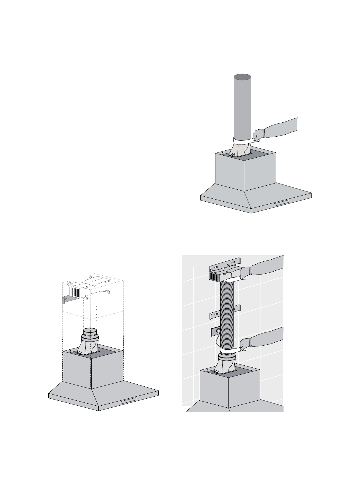
Fig. 11
Fig. 12
Fig. 10
INSTALLATION
Depending on the preferred installation/ducting mode,
follow step 14a or 14b below.
6a. Recirculating mode (Fig. 10). Using the centre line,
secure the recirculating T-piece to the wall with
suitable screws/fixings (optional kit AR610RK).
Install flexible pipe between T-piece and reducer.
Use cable ties or suitable duct tape to secure flexible pipe
to T-piece and reducer (Fig. 12)
NOTE: When installed in recirculating mode, it is
recommended to use a carbon filter (included in
recirculation kit AR610RK) to prevent odours being
emitted back into the room.
6b. Ducted mode (Fig. 11) Fit a 150mm diameter non
combustible flue pipe. Continue the centre line to
the ceiling. Fit flue pipe to the exhaust transition
duct. Use cable ties or suitable duct tape to secure
flue pipe to the transition duct.
Note: For ducted mode we recommend to extend the flue
pipe through the roof cladding (with appropriate flashing)
to an external roof cowl, venting the exhaust externally.
Some States allow venting into the ceiling cavity, enquiries
should be made with the local Government to ensure the
installation complies with the regulations.
NOTE: To ensure optimum performance of the
rangehood, the use of rigid ducting (optional AR150F)
is recommended. The use of bends should be avoided.
Rigid flexible ducting is suitable, although loose flexible
ducting is unacceptable. All ducting must be fire
retardant.
Loading ...
Loading ...
Loading ...