Loading ...
Loading ...
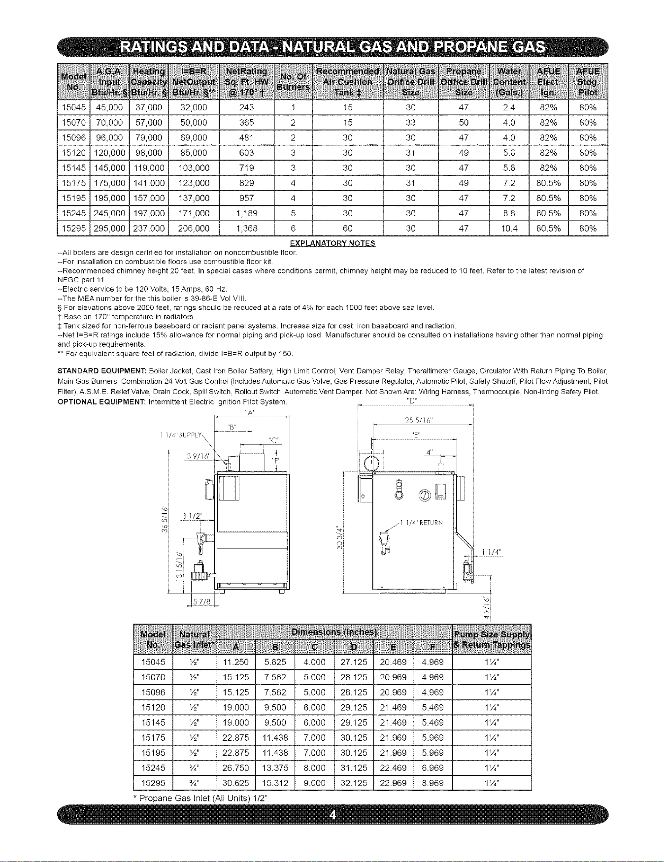
15045 45,000 37,000 32,000 243 1 15
15070 70,000 57,000 50,000 365 2 15
15096 96,000 79,000 69,000 481 2 30
15120 120,000 98,000 85,000 603 3 30
15145 145,000 119,000 I03,000 7t9 3 30
30 47 2.4 82% 80%
33 50 4.0 82% 80%
30 47 4.0 82% 80%
31 49 5.6 82% 80%
30 47 5.6 82% 80%
15175 175,000 141,000 I23,000 829 4 30 31 49 7.2 80.5% 80%
15195 195,000 157,000 137,000 957 4 30 30 47 7.2 80.5% 80%
15245 245,000 197,000 171,000 1,t89 5 30 30 47 8.8 80.5% 80%
15295 295,000 237,000 206,000 1,368 6 60 30 47 I0.4 80.5% 80%
HAll boilers are design certified for installation on noncombustible floor.
--For installation on combustible floors use combustible floor kit
--Recommended chimney height 20 feet In special cases where conditions permit, chimney height may be reduced to 10 feet Refer to the latest revision of
NFGC part 11.
--Electric service to be 120 Volts, 15 Am ps, 60 Hz
--The MEA number for the this boiler is 39-86-E Vol VIII
§ For elevations above 2000 feet, ratings should be reduced at a rate of 4% for each 1000 feet above sea level
1 Base on 170° temperature in radiators
:1:Tank sized for non-ferrous baseboard or radiant panel systems. Increase size for cast iron baseboard and radiation
--Net I=B=R ratings include 15% allowance for normal piping and pick-up load Manufacturer should be consulted on installations having other than normal piping
and pick-up requirements
** For equivalent square feet of radiation, divide I=B=R output by 150.
STANDARD EQUIPMENT: Boiler Jacket, Cast Iron Boiler Battery, High Limit Control, Vent Damper Relay, Theraltimeter Gauge, Circulator With Return Piping To Boiler,
Main Gas Burners, Combination 24 Volt Gas Control dnciudes Automatic Gas Valve, Gas Pressure Regulator, Automatic Pilot, Safety Shutoff, Pilot Flow Adjustment, Pilot
Filter), A.S.M.E. Relief Valve, Drain Cock, Spill Switch, Rollout Switch, Automatic Vent Damper Not Shown Are: Wiring Harness, Thermocouple, Nondinting Safety Pilot.
OPTIONAL EQUIPMENT: Intermittent Electbc Ignition PHot System.
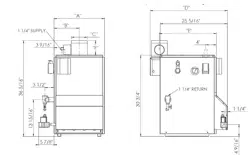
"A"
.....kB" _
"C"
.oi
5j ......
-o i
col
U U
'_D"
25 5/16"
"Z'
4"
. ,1 d ,
1 ]/4 IIREURN
%
1 1/4"
t
t
-oi
15045 ½" 11.250 5.625 4.000 27.125 20.469 4.969 1¼"
15070 ½" 15.125 7.562 5.000 28.125 20.969 4.969 1¼"
15096 ½" 15.125 7.562 5.000 28.125 20.969 4.969 1¼"
15120 ½" 19.000 9.500 6.000 29.125 21.469 5.469 1¼"
15145 ½" 19.000 9.500 6.000 29.125 21.469 5.469 1¼"
15175 ½" 22.875 11.438 7.000 30.125 21.969 5.969 1¼"
15195 ½" 22.875 11.438 7.000 30.125 21.969 5.969 1¼"
15245 ¾" 26.750 13.375 8.000 31.125 22.469 6.969 1¼"
15295 ¾" 30.625 15.312 9.000 32.125 22.969 8.969 1¼"
* Propane Gas Inlet (All Units) 1/2"
Loading ...
Loading ...
Loading ...