Loading ...
Loading ...
Loading ...
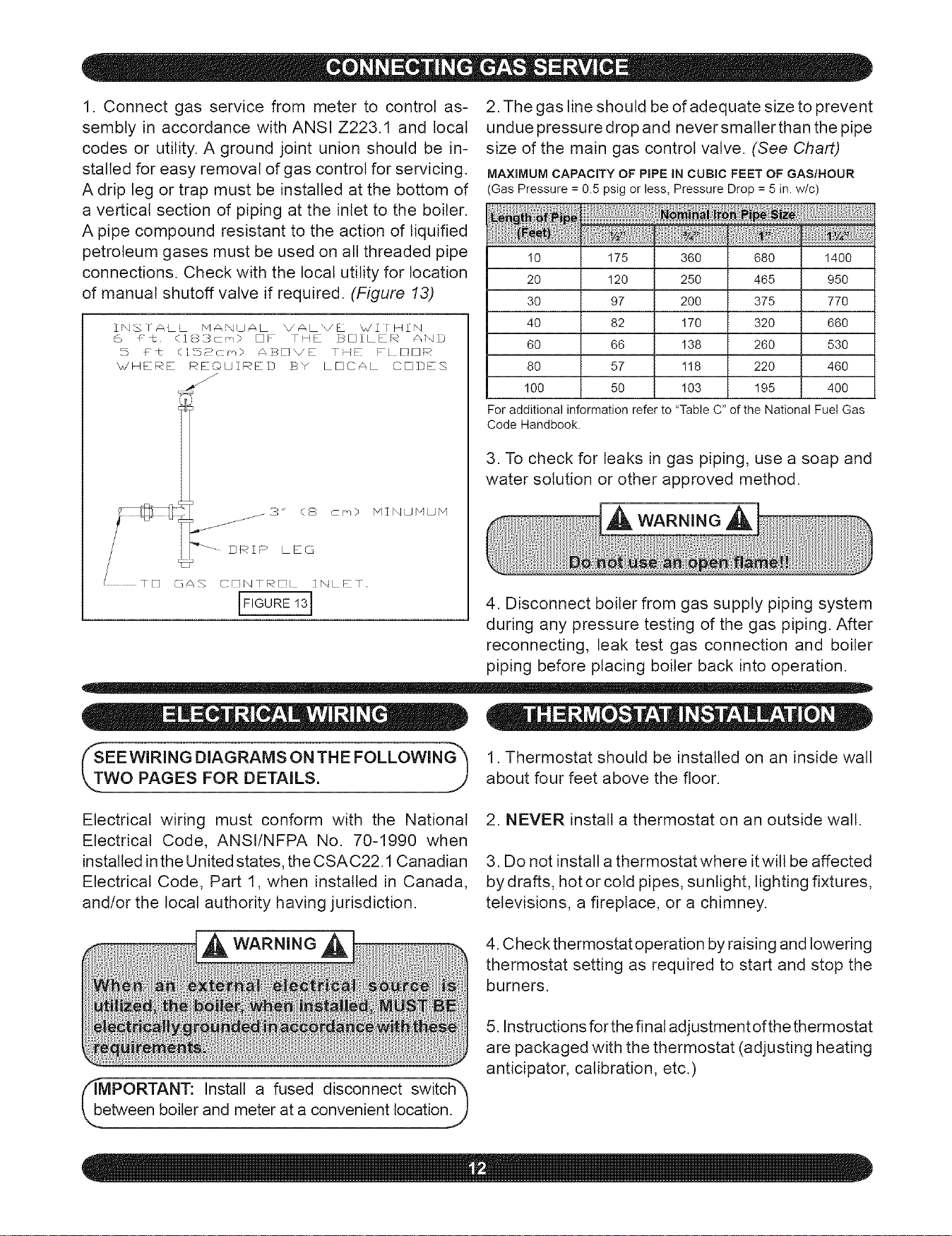
1. Connectgasservicefrom meterto controlas-
semblyin accordancewithANSIZ223.1andlocal
codesor utility.A groundjoint unionshouldbein-
stalledforeasyremovalofgascontrolforservicing.
Adriplegortrapmustbe installedatthebottomof
averticalsectionofpipingatthe inletto theboiler.
Apipecompoundresistanttotheactionof liquified
petroleumgasesmustbeusedonallthreadedpipe
connections.Checkwiththelocalutilityfor location
ofmanualshutoffvalveif required.(Figure 13)
INS IALL MANUAL VALVE %,/2/ HIM
6 #_. (183cm) EJ]F FH_ BOILER Z_ND
b £t (]5_crn) AB_VE T,_ FL NrqR
_/'FIE_E REOUIRED BY LEI]CAL CE]DE3
.3" (8 c_,)
_--- DRIP LEG
GAS CDNTRD ZNi ET
[Fl U .Sq
MINUMUM
2. The gas line should be of adequate size to prevent
undue pressure drop and neversmalter than the pipe
size of the main gas control valve. (See Chart)
MAXIMUM CAPACITY OF PiPE IN CUBIC FEET OF GAS/HOUR
(Gas Pressure = 0.5 psig or less, Pressure Drop = 5 in. w/c)
I0 175 360 680 1400
20 120 250 465 950
30 97 200 375 770
40 82 170 320 660
60 66 138 260 530
80 57 118 220 460
100 50 I03 195 400
Foradditionalinformation referto"Table C"ofthe National Fuel Gas
Code Handbook.
3. To check for leaks in gas piping, use a soap and
water solution or other approved method.
4. Disconnect boiler from gas supply piping system
during any pressure testing of the gas piping. After
reconnecting, leak test gas connection and boiler
piping before placing boiler back into operation.
SEE WIRING DIAGRAMS ON THE FOLLOWING_
WO PAGES FOR DETAILS. j/
Electrical wiring must conform with the National
Electrical Code, ANSI/NFPA No. 70-1990 when
installed in the United states, the CSAC22.1 Canadian
Electrical Code, Part 1, when installed in Canada
and/or the local authority having jurisdiction.
_h
IMPORTANT: Install a fused disconnect switchh
Lbetween boiler and meter at a convenient location S
1. Thermostat should be installed on an inside wall
about four feet above the floor.
2. NEVER install a thermostat on an outside wall.
3. Do not install a thermostat where it witl be affected
by drafts, hot or cold pipes, sunlight, lighting fixtures,
televisions, a fireplace, or a chimney.
4. Check thermostat operation by raising and lowering
thermostat setting as required to start and stop the
burners.
5. Instructions for the final adjustment of the thermostat
are packaged with the thermostat (adjusting heating
anticipator, calibration, etc.)
Loading ...
Loading ...
Loading ...