Loading ...
Loading ...
Loading ...
Oncemade,theseadjustmentsshouldremainaccurate.Takea littletimenowtofollow
thesedirectionscarefullytomaintaintheaccuracyofwhichyoursawiscapable.
RAILLOCKADJUSTMENT
(TighteningFenceClampingSystem) FIG.18
1.Locktheraillocklever(W).
2.Ontheundersideofthesaw,loosenthenut(LL)(Fig.18).
3.Tightenthehexrod(MM)untilthespringonthelockingsystem
iscompressedcreatingthedesiredtensionontheraillocklever. MM
Retightenthejamnutagainstthehexrod.
4.Flipthesawoverandcheckthatthefencedoesnotmovewhen LL
thelockleverisengaged.Ifthefenceisstillloose,tightenthe
springfurther.
RIPSCALEADJUSTMENT FIG,19
(CalibratingRipScale)
1.Unlocktheraillocklever(W).
2.Setthebladeat0° bevelandmovethe
fenceuntilitisflushwiththeblade.
3.Locktheraillocklever.
4.Loosenthescrews(NN,Fig.16)in
the rip scalepointerwitha Phillips
screwdriverandresettheredlineto0°
onthescale.
5.Tightenthescrewsbackintotherail. W
NOTE:Theripscaleonlyreadscorrectly
whenthefenceismountedontherightside
oftheblade.
BLADEALIGNMENTADJUSTMENT
(BladeParallelto MiterSlot)
AWARNING:Cut Hazard. Check the blade
at 0 ° and 45 ° to make sure blade does not
hit the throat plate, causing personal injury. FIG. 20
If the blade appears to be out of alignment
with the miter slot on the table top, it will
require calibration for alignment. To realign
the blade and miter slot, use the following
procedure:
1. Locate the black Allen Iocator screws
(OO) that hold up the trunnion to the
bottom of the table in the rear of the
saw.
2. Loosen both screws and align the blade
with the miter slot. Be sure to measure
between the miter slot and the back and
front of the blade to ensure parallelism.
3. Snugly tighten the screws to secure the
trunnion and blade assembly to the table CO
at the parallel position.
FENCE ALIGNMENT ADJUSTMENT (FIG. 4, 5) (Blade Parallel to Fence)
If you experience fence alignment problems and want to correct an out of parallel between
the fence and the blade, be sure to check the alignment of the blade to the miter slot first.
After confirming that those elements are aligned, proceed with alignment of the blade to the
fence using the following procedure:
1. Unlock the rail lock lever (W) and locate the two fence Iocator screws (AA) that support
the fence on the front and rear rails.
2. Loosen the rear Iocator screw and adjust the position of the fence in the groove on the
fence until it sets the fence face parallel to the blade. Make sure you measure from the
fence face to the front and back of the blade to ensure alignment.
3. Tighten the Iocator screw and repeat on the left side of the blade.
4. Check rip scale adjustment.
BEVEL STOP AND POINTER ADJUSTMENT
(Calibrating Bevel Scale)
Calibrating the bevel system on the saw may require two separate steps, one for the bevel
scale and another for the bevel pointer. The scale should always be checked first followed
by adjustments to the red pointer.
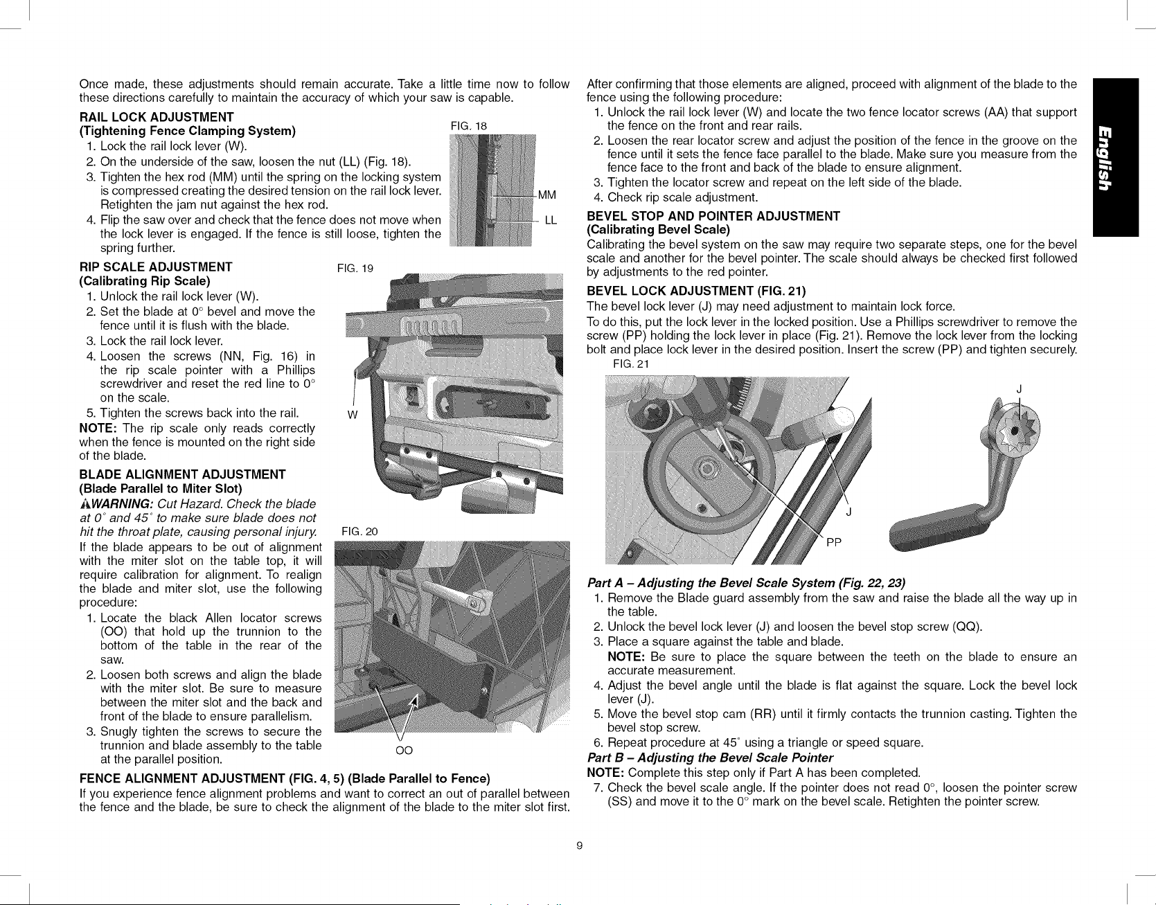
BEVEL LOCK ADJUSTMENT (FIG. 21)
The bevel lock lever (J) may need adjustment to maintain lock force.
To do this, put the lock lever in the locked position. Use a Phillips screwdriver to remove the
screw (PP) holding the lock lever in place (Fig. 21 ). Remove the lock lever from the locking
bolt and place lock lever in the desired position. Insert the screw (PP) and tighten securely.
FIG. 21
PP
Part A - Adjusting the Bevel Scale System (Fig. 22, 23)
1. Remove the Blade guard assembly from the saw and raise the blade all the way up in
the table.
2. Unlock the bevel lock lever (J) and loosen the bevel stop screw (QQ).
3. Place a square against the table and blade.
NOTE: Be sure to place the square between the teeth on the blade to ensure an
accurate measurement.
4. Adjust the bevel angle until the blade is flat against the square. Lock the bevel lock
lever (J).
5. Move the bevel stop cam (RR) until it firmly contacts the trunnion casting. Tighten the
bevel stop screw.
6. Repeat procedure at 45 ° using a triangle or speed square.
Part B - Adjusting the Bevel Scale Pointer
NOTE: Complete this step only if Part A has been completed.
7. Check the bevel scale angle. If the pointer does not read 0°, loosen the pointer screw
(SS) and move it to the 0° mark on the bevel scale. Retighten the pointer screw.
Loading ...
Loading ...
Loading ...