Loading ...
Loading ...
Loading ...
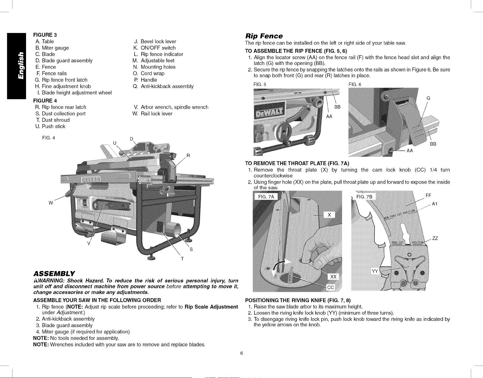
FIGURE 3
A. Table
B. Miter gauge
C. Blade
D. Blade guard assembly
E. Fence
R Fence rails
G. Rip fence front latch
H. Fine adjustment knob
I. Blade height adjustment wheel
FIGURE 4
R. Rip fence rear latch
S. Dust collection port
T. Dust shroud
U. Push stick
J. Bevel lock lever
K. ON/OFF switch
L. Rip fence indicator
M. Adjustable feet
N. Mounting holes
O. Cord wrap
P. Handle
Q. Anti-kickback assembly
V. Arbor wrench, spindle wrench
W. Rail lock lever
FIG. 4
W
V
S
T
ASSEMBLY
i_WARNING: Shock Hazard. To reduce the risk of serious personal injury, turn
unit off and disconnect machine from power source before attempting to move it,
change accessories or make any adjustments.
ASSEMBLE YOUR SAW INTHE FOLLOWING ORDER
1. Rip fence (NOTE: Adjust rip scale before proceeding; refer to Rip Scale Adjustment
under Adjustment.)
2. Anti-kickback assembly
3. Blade guard assembly
4. Miter gauge (if required for application)
NOTE: No tools needed for assembly.
NOTE: Wrenches included with your saw are to remove and replace blades.
Rip Fence
The rip fence can be installed on the left or right side of your table saw.
TO ASSEMBLE THE RIP FENCE (FIG. 5, 6)
1. Align the Iocator screw (AA) on the fence rail (F) with the fence head slot and align the
latch (G) with the opening (BB).
2. Secure the rip fence by snapping the latches onto the rails as shown in Figure 6. Be sure
to snap both front (G) and rear (R) latches in place.
FIG. 5 FIG. 6
G
AA
BB
TO REMOVE THE THROAT PLATE (FIG. 7A)
1. Remove the throat plate (X) by turning the cam lock knob (CC) 1/4 turn
counterclockwise
2. Using finger hole (XX) on the plate, pull throat plate up and forward to expose the inside
of the saw.
FIG. 7B
FF
iiiiiiiiiiiiiiiiiiiiiiiiiiiiiiiiiiiiiiiiiiiiiiiiw
POSITIONING THE RIVING KNIFE (FIG. 7, 8)
1. Raise the saw blade arbor to its maximum height.
2. Loosen the riving knife lock knob (YY) (minimum of three turns).
3. To disengage riving knife lock pin, push lock knob toward the riving knife as indicated by
the yellow arrows on the knob.
Loading ...
Loading ...
Loading ...