Loading ...
Loading ...
Loading ...
PAGE: 6 / 9
F A N C OF A N C O
Tighten blades to blade brackets by
using blade screws and washers.
Screw
Canopy
Fig.12
Fig.13
Blade Screw
Washer
Blade Bracket
Blade
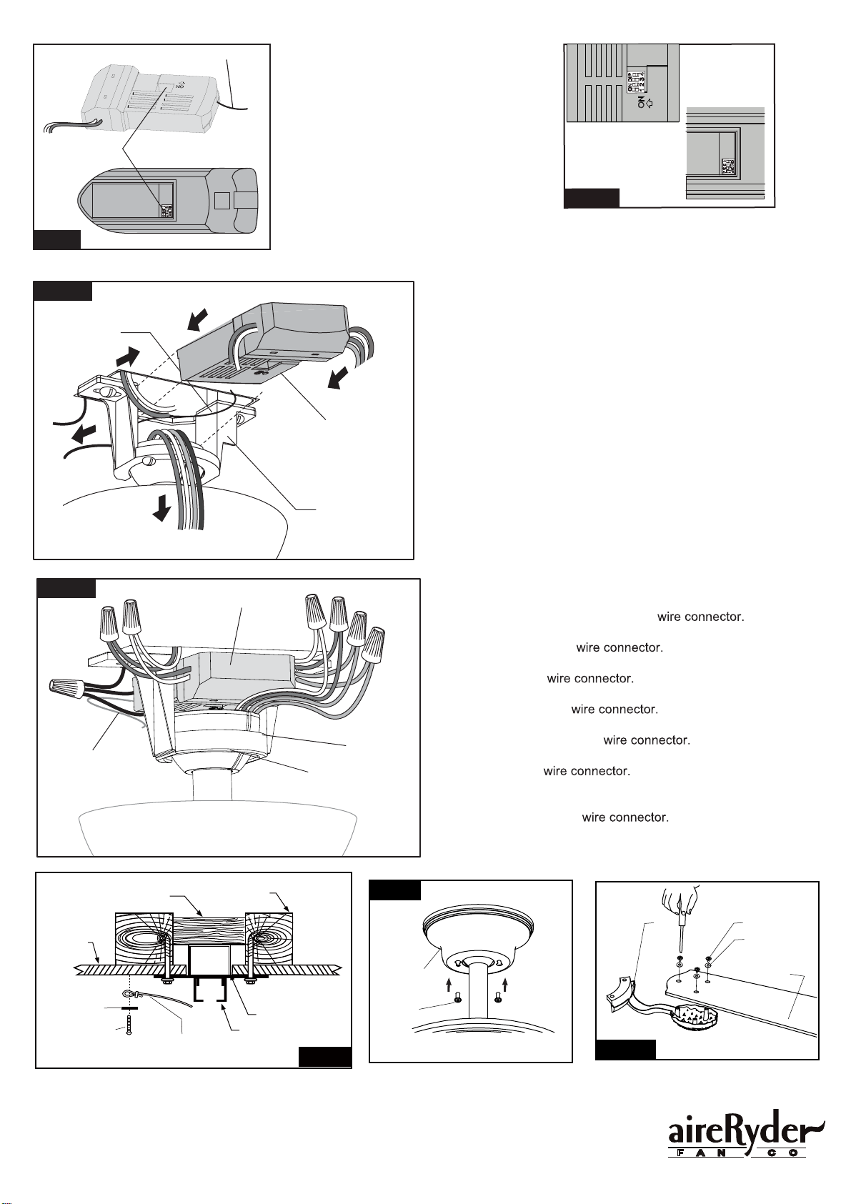
Secure the canopy to hanger
bracket with screws.
Fig.11
Attach the loop at the end of the safety cable to
the ceiling surface, then secure it with a flat
washer and dry wall screw. Make sure the flat
washer and dry wall screw are covered by the
fan canopy
Flat Washer
Safety Cable
Dry Wall Screw
Ceiling
Hanger Bracket
Ceiling Joist
Wood Member
(2" x 4" Approx.)
Junction Box
Fig.9
Move Ground Wires (a), Outlet Box wires (b), and
Motor Wires (c) away from the center of the Hanger
Bracket. Then slide Receiver through Hanger
Bracket as shown, Antenna end first, until it is
centered. Finally, cut Motor Wires (c) to length
needed for connections.
Antenna
Receiver
Hanger Bracket
Code example:
1-ON 2-OFF 3-ON 4-OFF
on both DIP Switches.
a.
c.
Fig.8
Antenna
DIP Switch
Transmitter
Receiver
Fig.8a
There is a code switch in the transmitter and
receiver. This "DIP Switch" is a 4 key unit
(Fig.8). All keys were set at "ON" position in
the beginning. Set the keys to a different code.
Make sure the same numbered keys are
switched "ON" for both DIP Switches (Fig.8a).
Take note that the "ON" position may have
different orientation for each.
Fig.10
Hanger
Bracket
Hanger Ball
Receiver
7 .
1 .
5 .
6 .
2 .
3 .
4 .
Antenna:
DO NOT CUT
OR SPLICE
Make wire connections:
1) The Motor white (neutral) wire to the white (neutral) "To
Motor N" wire from Receiver with a
2) The Motor black (hot) wire to the black (hot) "To Motor L" wire
from Receiver with a
3) The Motor blue wire to the blue "For Bottom Light" wire from
Receiver with a
4) The Motor orange wire to the orange "For Upper Light" wire
from receiver with a
5) The white (neutral) wire from Outlet Box to the white "AC in N"
wire from Receiver with a
6) The black wire from Outlet Box to the black "AC in L" wire from
Receiver with a
7) The ground wire from Outlet Box to the green ground wire
from the Hanger Ball and the green ground wire from the
Hanger Bracket with a
Make sure all of wire connectors are connected firmly.
***Tuck all wire connectors and wires carefully up into the Outlet Box,
EXCEPT antenna, which should remain outside Outlet Box.
b.
190104
Loading ...
Loading ...
Loading ...