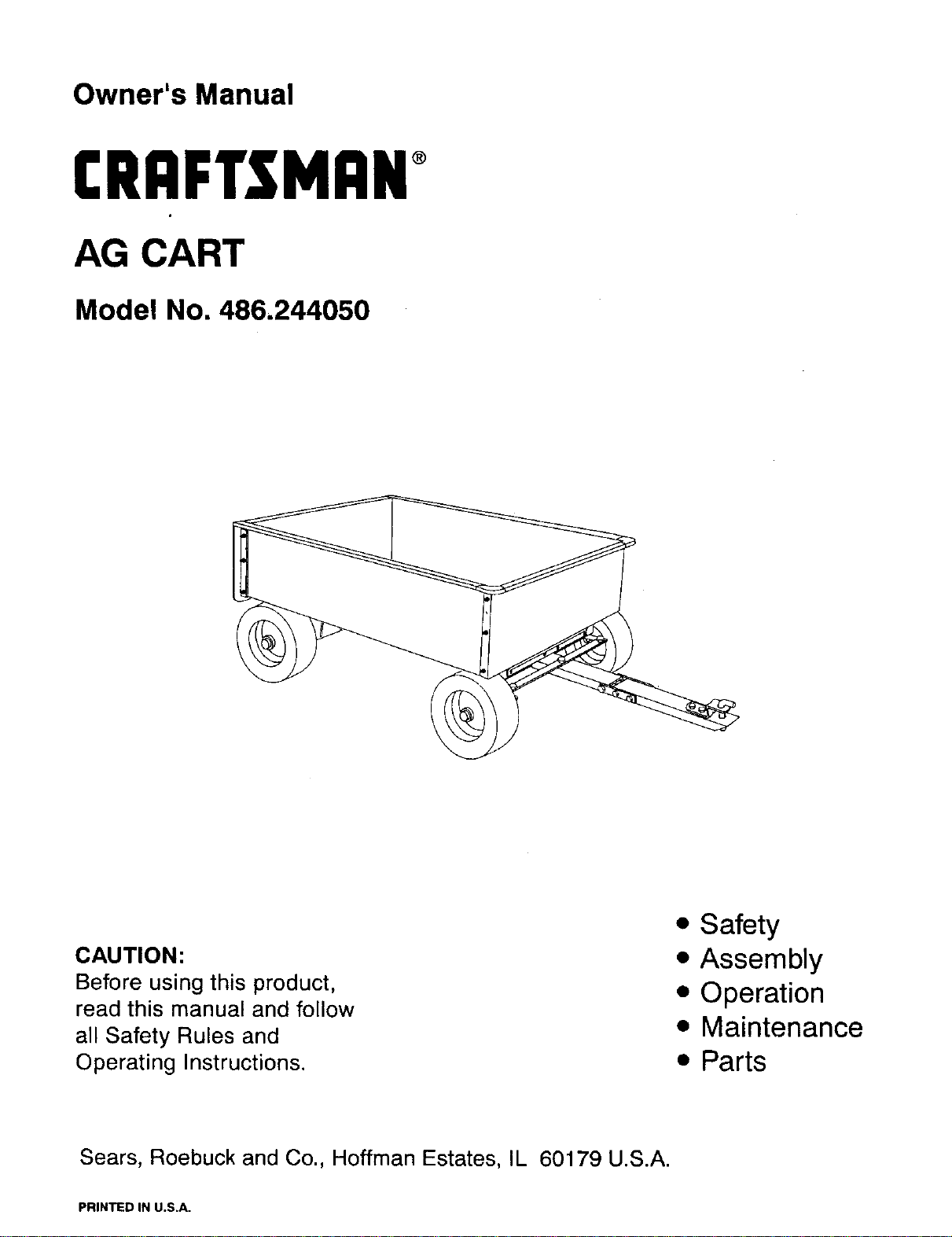
Owner's Manual
CRRFTSMRN
AG CART
Model No. 486.244050
CAUTION:
Before using this product,
read this manual and follow
all Safety Rules and
Operating Instructions.
• Safety
• Assembly
• Operation
• Maintenance
• Parts
Sears, Roebuck and Co., Hoffman Estates, IL 60179 U.S.A.
PRINTED IN U.S.A.
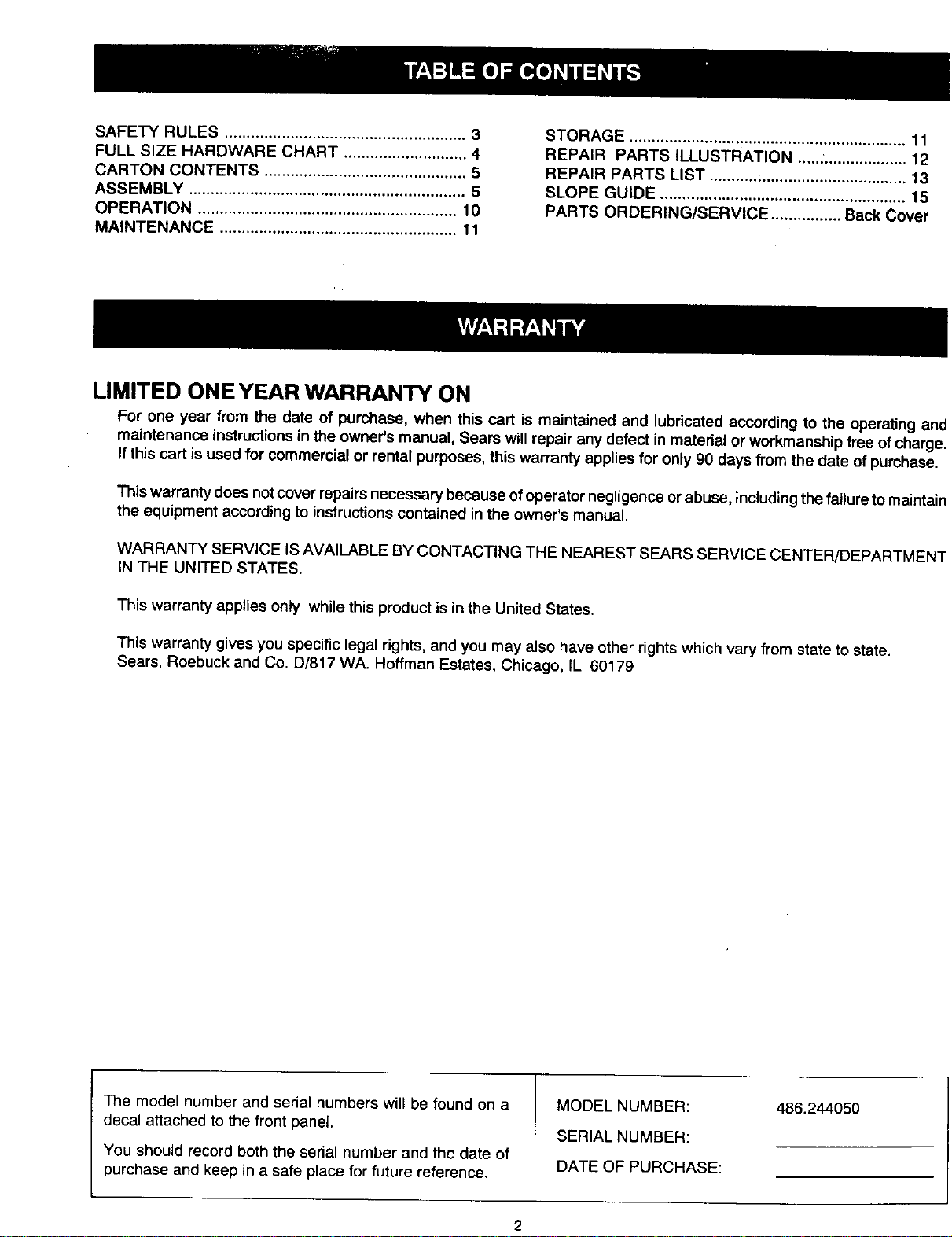
SAFETY RULES ....................................................... 3
FULL SIZE HARDWARE CHART ............................ 4
CARTON CONTENTS .............................................. 5
ASSEMBLY ............................................................... 5
OPERATION ........................................................... 10
MAINTENANCE ...................................................... 11
STORAGE ............................................................... 11
REPAIR PARTS ILLUSTRATION .....:................... 12
REPAIR PARTS LIST ............................................. 13
SLOPE GUIDE ........................................................ 15
PARTS ORDERING/SERVICE ................ Back Cover
LIMITED ONE YEAR WARRANTY ON
For one year from the date of purchase, when this cart is maintained and lubricated according to the operating and
maintenance instructions in the owner's manual, Sears will repair any defect in material or workmanship free of charge.
If this cart is used for commercial or rental purposes, this warranty applies for only 90 days from the date of purchase.
This warranty does not cover repairs necessary because of operator negligence or abuse, including the failure to maintain
the equipment according to instructions contained in the owner's manual.
WARRANTY SERVICE IS AVAILABLE BY CONTACTING THE NEAREST SEARS SERVICE CENTER/DEPARTMENT
IN THE UNITED STATES.
This warranty applies only while this product is in the United States.
This warranty gives you specific legal rights, and you may also have other rights which vary from state to state.
Sears, Roebuck and Co. D/817 WA. Hoffman Estates, Chicago, IL 60179
The model number and serial numbers wil_be found on a
decal attached to the front panel.
You should record both the serial number and the date of
purchase and keep in a safe place for future reference.
MODEL NUMBER:
SERIAL NUMBER:
DATE OF PURCHASE:
486.244050
Any power equipment can cause injury if operated improperly or if the user does not understand how to operate
the equipment. Exercise caution at all times, when using power equipment.
Exercise caution at all times when using power
equipment.
Read this owners manual before attempting to
assemble or operate the cart.
Read the vehicle owners manual and know how to
operate your tractor, before using the cart attach-
ment.
Do not at any time carry passengers in this cart. It has
not been designed to carry passengers.
Never allow children to operate the tractor or the cart
attachment.
Do not allow adults to operate the tractor or cart
attachment without proper instructions.
Always begin with the transmission in first (low) and
gradually increase speed as conditions permit.
Tow the cart at reduced speed over rough terrain and
hillsides or near creeks and ditches to prevent tipping
over and loss of control. Do not drive too close to a
creek or ditch.
Vehicle braking and stability may be affected with the
attachment of this cart. Do not fill cart to maximum
weight capacity without checking the capability of the
towing vehicle to safely pull and stop with the cart
attached.
Before operating vehicle on any grade (hill) refer to
the safety rules in the vehicle owner's manual con-
cerning safe operation on slopes. Refer also to the
slope guide on page 15 of this manual. Stay off
steep slopest
• Do not unhook your cart from the tractor while on a
slope. The cart could unexpectedly roll down the
slope.
• Do not tow this cart on highways or on public thor-
oughfares.
• Maximum towing speed is 10 m.p.h.
• Follow maintenance and lubrication instructions as
outlined in this manual.
,_ Look for this symbol to point out important safety precautions. It mean--Attention!!
Become alertH Your safety is involved.
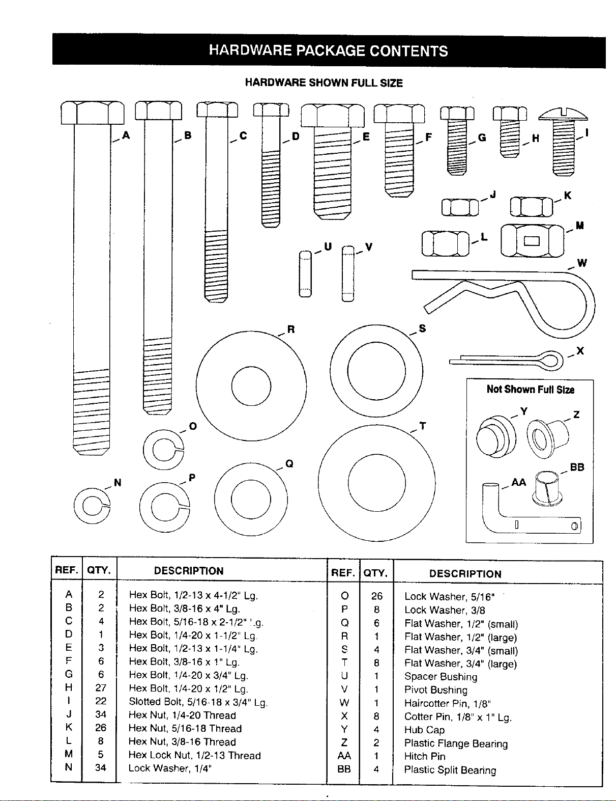
HARDWARE SHOWN FULL SIZE
BB
REF.
A
B
C
D
E
F
G
H
I
J
K
L
M
N
QTY.
2
2
4
1
6
6
27
22
34
26
8
5
34
DESCRIPTION
REF. IQTY, DESCRIPTION
,=xBolt, 1/2-13 x 4-1/2" Lg.
,_xBolt, 3/8-16 x 4" Lg.
!x Bolt, 5/16-18 x 2-1/2" l.g.
.'x Bolt, 1/4-20 x 1-1/2" Lg.
;x Bolt, 1/2-13 x 1-1/4" Lg,
.=xBolt, 3/8-16 x 1" Lg.
._xBolt, !/4-20 x 3/4" Lg.
.'x Bolt, 1/4-20 x 1/2" Lg.
3tted Bolt, 5/16-16 x 3/4" Lg
._xNut, 1/4-20 Thread
.'x Nut, 5/16-18 Thread
._xNut, 3/8-16 Thread
._xLock Nut, 1/2-13 Thread
,ck Washer, 1/4"
O 26
P 8
Q 6
R 1
S 4
T 8
U 1
V 1
W 1
X 8
Y 4
Z 2
AA 1
BB 4
Lock Washer, 5/16"
Lock Washer, 3/8
Flat Washer, 1/2" (small)
Flat Washer, 1/2" (large)
Flat Washer, 3/4" (small)
Flat Washer, 3/4" (large)
Spacer Bushing
Pivot Bushing
Haircotter Pin, 1/8"
Cotter Pin, 1/8" x 1" Lg.
Hub Cap
Plastic Flange Bearing
Hitch Pin
Plastic Split Bearing
15
3
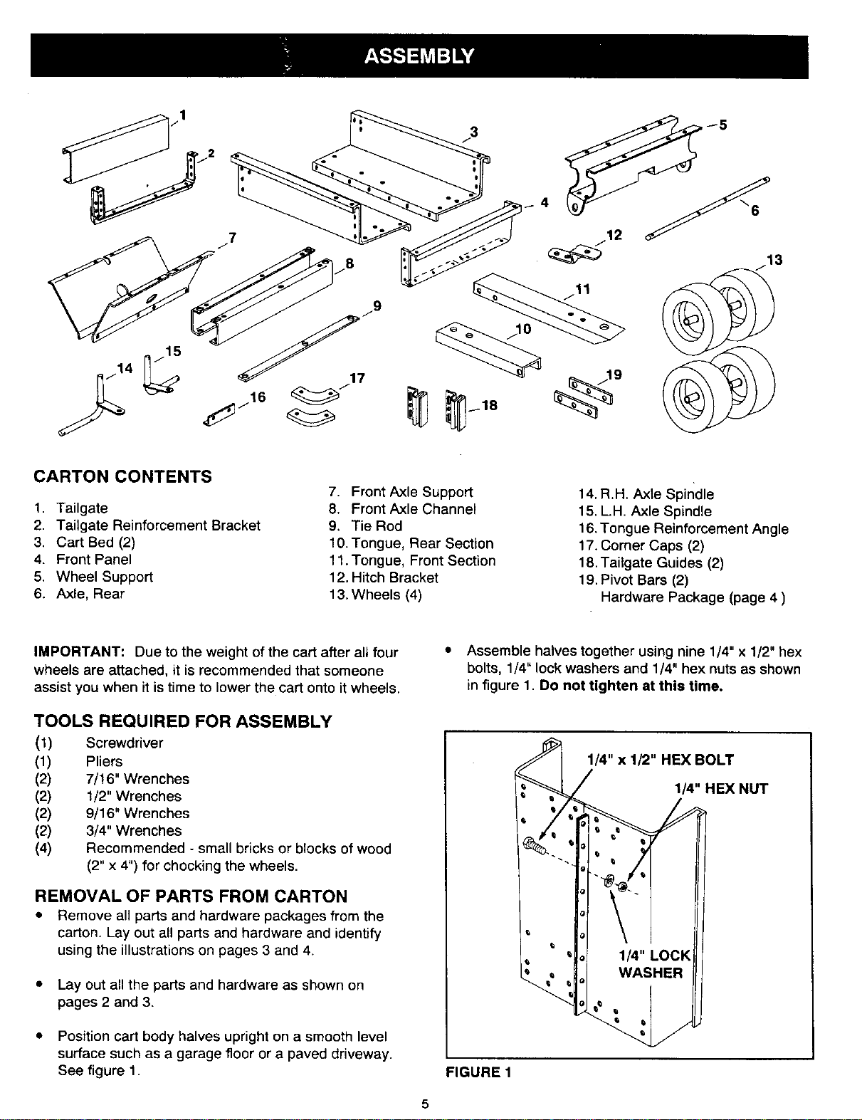
CARTON CONTENTS
1. Tailgate
2. Tailgate Reinforcement Bracket
3. Cart Bed (2)
4. Front Panel
5. Wheel Support
6. Axle, Rear
7. Front Axle Support
8. Front Axle Channel
9. Tie Rod
10. Tongue, Rear Section
11. Tongue, Front Section
12. Hitch Bracket
13. Wheels (4)
14. R.H. Axle Spindle
15. L.H. Axle Spindle
16. Tongue Reinforcement Angle
17. Corner Caps (2)
18. Tailgate Guides (2)
19. Pivot Bars (2)
Hardware Package (page 4 )
IMPORTANT: Due to the weight of the cart after all four
wheels are attached, it is recommended that someone
assist you when it is time to lower the cart onto it wheels.
TOOLS REQUIRED FOR ASSEMBLY
(1) Screwdriver
(1) Pliers
(2) 7/16" Wrenches
(2) 1/2" Wrenches
(2) 9/16" Wrenches
(2) 3/4" Wrenches
(4) Recommended - small bricks or blocks of wood
(2" x 4") for chocking the wheels,
REMOVAL OF PARTS FROM CARTON
• Remove all parts and hardware packages from the
carton. Lay out all parts and hardware and identify
using the illustrations on pages 3 and 4.
• Lay out all the parts and hardware as shown on
pages 2 and 3.
• Position cart body halves upright on a smooth level
surface such as a garage floor or a paved driveway.
See figure 1.
• Assemble halves together using nine 1/4" x 1/2" hex
bolts, 1/4" lock washers and 1/4" hex nuts as shown
in figure 1. Do not tighten at this time.
1/4" x 1/2" HEX BOLT
1/4" HEX NUT
FIGURE 1
5
&
CAUTION: Do not leave the cart unat-
tended in an upright position. A falling cart
can cause injury. Pay close attention to the
stability of the cart while it is in an upright
position. For best stability, assemble the cart
on a smooth, level surface.
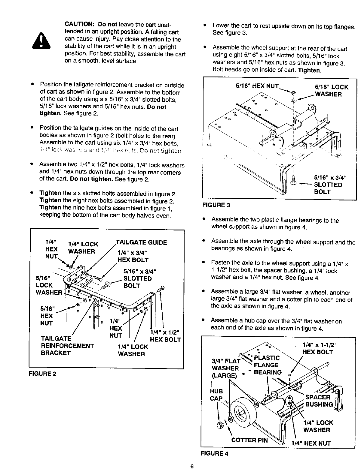
Position the tailgate reinforcement bracket on outside
of cart as shown in figure 2. Assemble to the bottom
of the cart body using six 5/16" x 3/4" slotted bo_ts,
5/16" lock washers and 5/16" hex nuts. Do not
tighten. See figure 2.
Position the tailgate guides on the inside of the cart
bodies as shown in figure 2 (bolt holes to the rear).
Assemble to the cart using six 1/4" x 3/4" hex bolts,
i.,'_" lo_-kwa._i _:s and _,,' !_, _,_t_ Do net tighte! _,
• Assemble two 1/4" x 1/2" hex bolts, 1/4" lock washers
and 1/4" hex nuts down through the top rear corners
of the cart. Do not tighten. See figure 2.
• Tighten the six slotted bolts assembled in figure 2.
Tighten the eight hex bolts assembled in figure 2.
Tighten the nine hex bolts assembled in figure 1,
keeping the bottom of the cart body halves even.
1/4" 1/4" LOCK tilDE
HEX WASHER 1/4" x 3/4"
NUT, HEX BOLT
5/16" x 3/4"
5/16" "_ SLO'I-rED
LOCK
WASHER_
5/16"
HEX
NUT ©
1/4"
HEX
1/4" 1/2"
TAILGATE NUT HEX BOLT
REINFORCEMENT 1/4" LOCK
BRACKET WASHER
FIGURE 2
Lower the cart to rest upside down on its top flanges.
See figure 3.
Assemble the wheel support at the rear of the cart
using eight 5/16" x 3/4" slotted bolts, 5/16" lock
washers and 5/16" hex nuts as shown in figure 3.
Bolt heads go on inside of cart. Tighten.
FIGURE3
• Assemble the two plastic flange bearings to the
wheel support as shown in figure 4.
• Assemble the axle through the wheel support and the
bearings as shown in figure 4.
• Fasten the axle to the wheel support using a 1/4" x
1-1/2" hex bolt, the spacer bushing, a 1/4" lock
washer and a 1/4" hex nut. See figure 4.
• Assemble a large 3/4" flat washer, a wheel, another
large 3/4" flat washer and a cotter pin to each end of
the axle as shown in figure 4.
• Assemble a hub cap over the 3/4" flat washer on
each end of the axle as shown in figure 4.
3/4"
WASHER
(LAR(E)
HUB
1/4" x 1-1/2"
HEX BOLT
SPACER
BUSHING
FIGURE4
co'n'ER PII_
1/4"LOCK
WASHER
I_"HF-XNUT
6
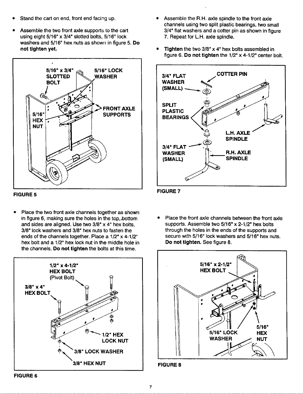
Standthecartonend,frontendfacingup.
Assemble the two front axle supports to the cart
using eight 5/16"x 3/4" slotted bolts, 5/16" lock
washers and 5/16" hex nuts as shown in figure 5. Do
not tighten yet.
Assemble the R.H. axle spindle to the front axle
channels using two split plastic bearings, two small
3/4" flat washers and a cotter pin as shown in figure
7. Repeat for L.H. axle spindle.
Tighten the two 3/8" x 4" hex bolts assembled in
figure 6. Do not tighten the 1/2" x 4-1/2" center bolt.
5/16" x 3/4" _ 5/16" LOCK
SLOTTEDI -- WASHER
5/1 j,.._-_" .,____-_ SUPPORTS
,
FIGURE 5
3/4" FLAT COTTER PIN
3/4" FLAT "'_ '_ SPINDLE
WASHER "_'" R.H. AXLE
(SMALL) _ SPINDLE.
FIGURE 7
Place the two front axle channels together as shown
in figure 6, making sure the holes in the top, ,bottom
and sides are aligned. Use two 3/8" x 4" hex bolts,
3/8" lock washers and 3/8" hex nuts to fasten the
ends of the channels together. Place a 1/2" x 4-1/2"
hex bolt and a 1/2" hex lock nut in the middle hole in
the channels. Do not tighten the bolts at this time.
Place the front axle channels between the front axle
supports. Assemble two 5/16" x 2-1/2" hex bolts
through the holes in the ends of the supports and
secure with 5/16" lock washers and 5/16" hex nuts.
Do not tighten. See figure 8.
1/2" x 4-1/2"
HEX BOLT
(Pivot Bolt).
mmr.
FIGURE 6
FIGURE 8
5/16" x 2-1/2"
HEX BOLT
\
5/16"
5/16" LOCK HEX
7
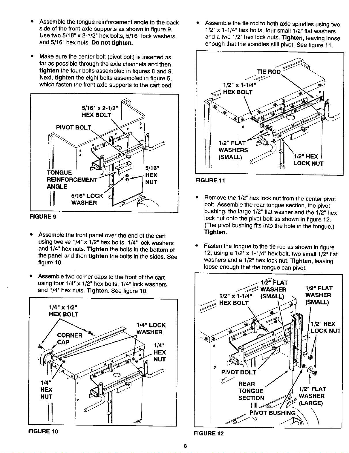
Assemble the tongue reinforcement angle to the back
side of the front axle supports as shown in figure g.
Use two 5/16" x 2-1/2" hex bolts, 5/16" lock washers
and 5/16" hex nuts. Do not tighten.
Make sure the center bolt (pivot bolt) is inserted as
far as possible through the axle channels and then
tighten the four bolts assembled in figures 8 and 9.
Next, tighten the eight bolts assembled in figure 5,
which fasten the front axle supports to the cart bed.
5/16" x 2-1/2"
HEX BOLT
PIVOT BOLT
TONGUE
REINFORCEMENT
ANGLE
/1t
5/16"
HEX
NUT
FIGURE 9
• Assemble the front panel over the end of the cart
using twelve 1/4" x 1/2" hex bolts, 1/4" lock washers
and 1/4" hex nuts. Tighten the bolts in the bottom of
the panel and then tighten the bolts in the sides. See
figure 10.
• Assemble two corner caps to the front of the cart
using four 1/4" x 1/2" hex bolts, 1/4" lock washers
and 1/4" hex nuts. Tighten. See figure 10.
1/4" x 1/2"
HEX BOLT
I_"LOCK
WASHER
1/4"
HEX
NUT
1/4"
HEX
NUT
FIGURE 10
Assemble the tie rod to both axle spindles using two
1/2" x 1-1/4" hex bolts, four small 1/2" flat washers
and a two 1/2" hex lock nuts. Tighten, leaving loose
enough that the spindles stillpivot. See figure 11.
TIE ROD
1/2" x 1-1/4"
HEX BOLT
1/2" FLAT
(SMALL)
r
1/2" HEX
LOCK NUT
FIGURE 11
Remove the 1/2" hex lock nut from the center pivot
bolt. Assemble the rear tongue section, the pivot
bushing, the large 1/2" flat washer and the 1/2" hex
lock nut onto the pivot bolt as shown in figure 12.
(The pivot bushing fits into the hole in the tongue.)
Tighten.
Fasten the tongue to the tie rod as shown in figure
12, using a 1/2" x 1-1/4" hex bolt, two small 1/2" fiat
washers and a 1/2" hex lock nut. Tighten, leaving
loose enough that the tongue can pivot.
..F_ 1,/_'_:LAT
WASHER 1/2" FLAT
1/2" x 1-1/4" (SMALL) WASHER
HEX BOLT (SMALL)
I_"HEX
LOCKNUT
SECTION
1/2"FLAT
WASHER
_P_VOTBUSHING
FIGURE 12
8
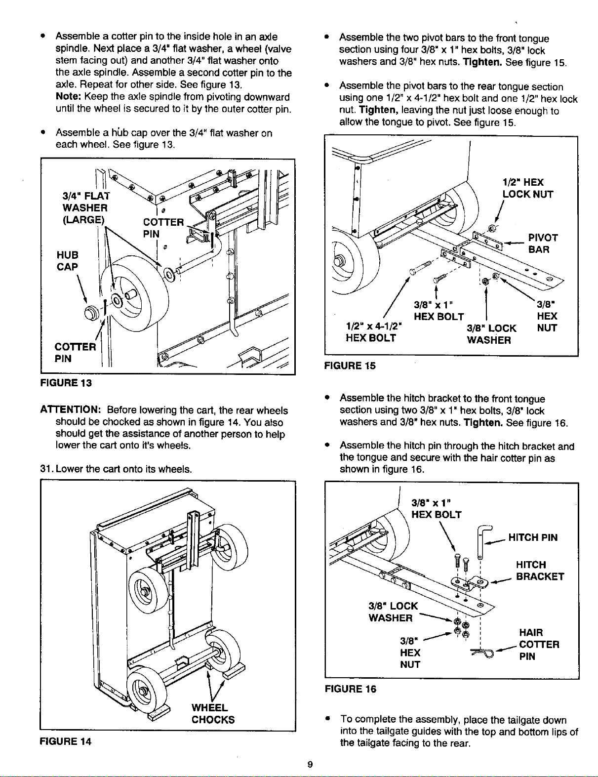
Assemble a cotter pin to the inside hole in an axle
spindle. Next place a 3/4" flat washer, a wheel (valve
stem facing out) and another 3/4" flat washer onto
the axle spindle. Assemble a second cotter pin to the
axle. Repeat for other side. See figure 13.
Note: Keep the axle spindle from pivoting downward
until the wheel is secured to it by the outer cotter pin.
Assemble a h{Jbcap over the 3/4" flat washer on
each wheel. See figure 13.
3/4" FLAT
WASHER
(LARGE) COTTER
HUB
CAP
\
COTTER /
PIN
FIGURE 13
ATTENTION: Before lowering the cart, the rear wheels
should be chocked as shown in figure 14. You atso
should get the assistance of another person to help
lower the cart onto it'swheels.
31. Lower the cart onto its wheels.
WHEEL
CHOCKS
FIGURE 14
Assemble the two pivot bars to the front tongue
section using four 3/8" x 1" hex bolts, 3/8" lock
washers and 3/8" hex nuts. Tighten. See figure 15.
Assemble the pivot bars to the rear tongue section
using one 1/2" x 4-1/2" hex bolt and one 1/2" hex lock
nut. Tighten, leaving the nut just loose enough to
allow the tongue to pivot. See figure 15.
1/2" x 4-1/2"
HEX BOLT
1/2" HEX
LOCK NUT
/
PIVOT
j BAR
' 1
3/8" x 1" 3/8 •
HEX BOLT HEX
3/8" LOCK NUT
WASHER
FIGURE 15
• Assemble the hitch bracket to the front tongue
section using two 3/8" x 1" hex bolts, 3/8" lock
washers and 3/8" hex nuts. Tighten. See figure 16.
• Assemble the hitch pin through the hitch bracket and
the tongue and secure with the hair cotter pin as
shown in figure 16.
FIGURE 16
• To complete the assembly, place the tailgate down
into the tailgate guides with the top and bottom lips of
the tailgate facing to the rear.
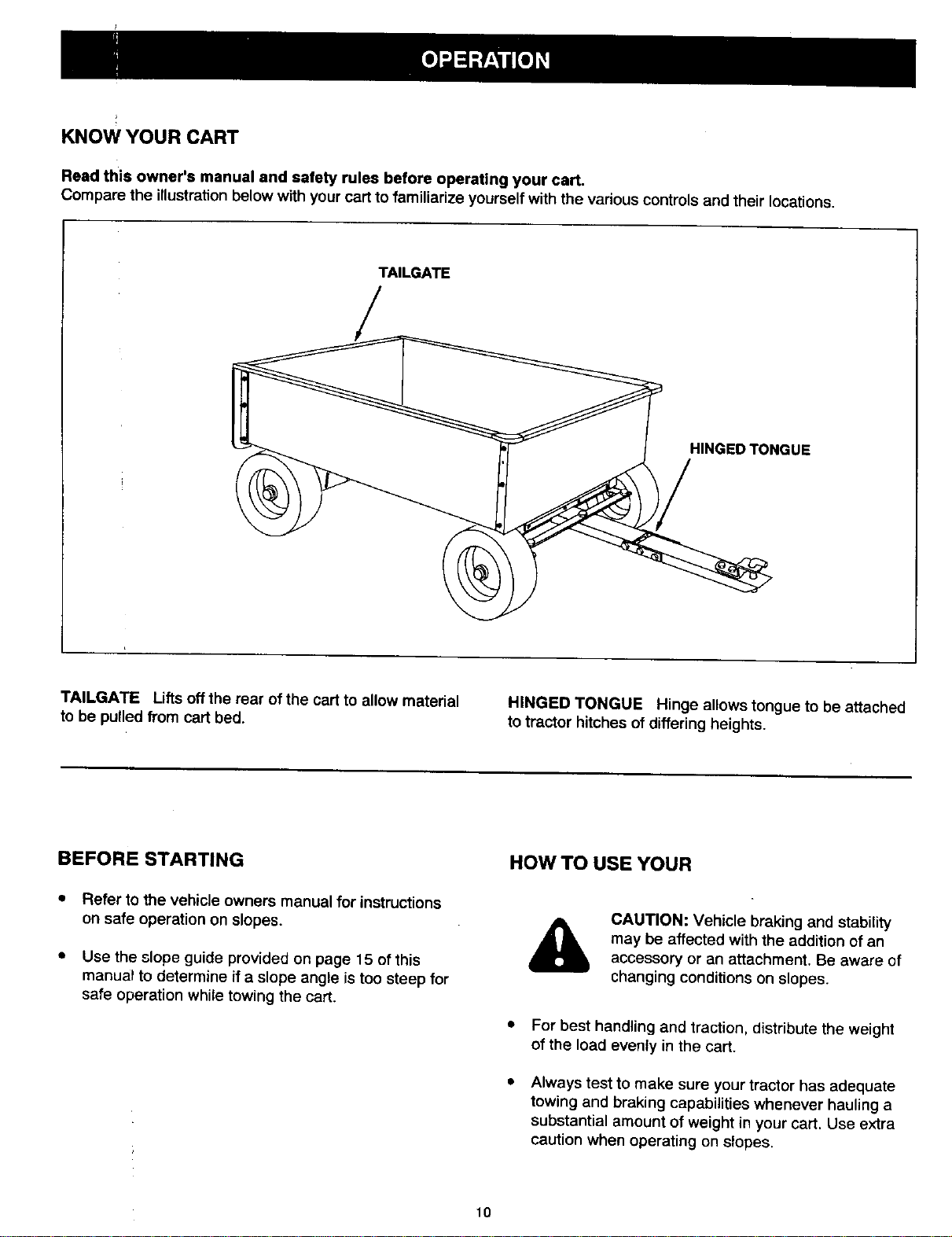
KNOW YOUR CART
Read this owner's manual and safety rules before operating your cart.
Compare the illustra_on below with your cart to familiarize yourself with the various controls and their locations.
TAILGATE
HINGED TONGUE
TAILGATE Liftsoff the rear of the cart to allow material
to be pulled from cart bed.
HINGED TONGUE Hinge allows tongue to be attached
to tractor hitches of differing heights.
BEFORESTARTING HOWTO USE YOUR
Refer to the vehicle owners manual for instructions
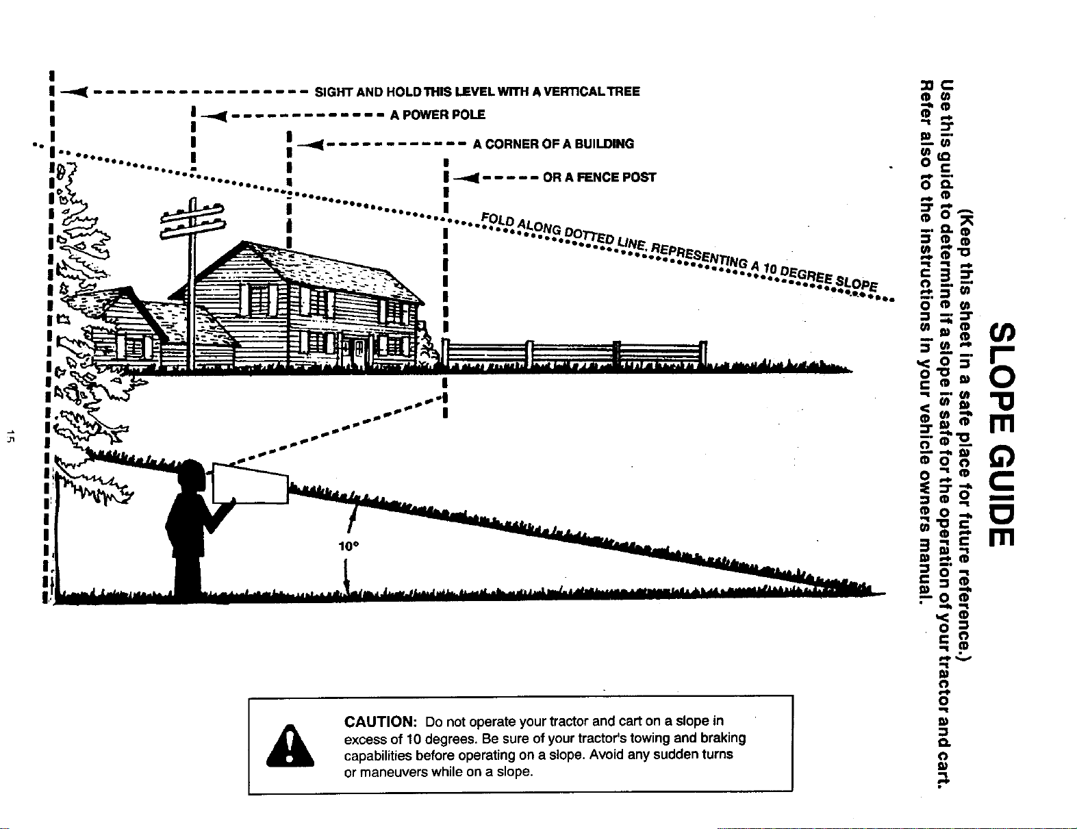
on safe operation on slopes.
Use the slope guide provided on page 15 of this
manual to determine if a slope angle istoo steep for
safe operation while towing the cart.
&
CAUTION: Vehicle braking and stability
may be affected with the addition of an
accessory or an attachment. Be aware of
changing conditions on stopes.
• For best handling and traction, distribute the weight
of the load evenly in the cart.
Always test to make sure your tractor has adequate
towing and braking capabilities whenever hauling a
substantial amount of weight in your cart. Use extra
caution when operating on slopes.
10
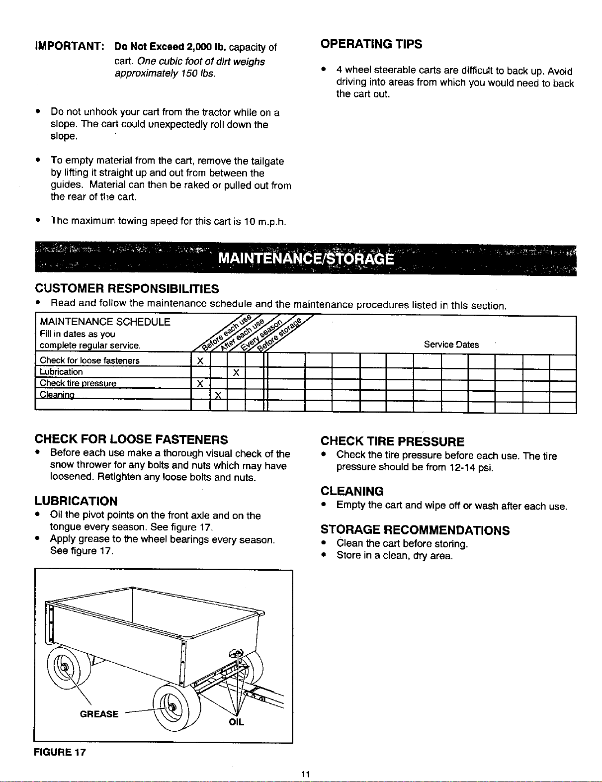
IMPORTANT: Do Not Exceed 2,000 lb. capacity of
cart. One cubic foot of dirt weighs
approximately !50 Ibs.
Do not unhook your cart from the tractor while on a
slope. The cart could unexpectedly roll down the
slope.
To empty material from the cart, remove the tailgate
by lifting it straight up and out from between the
guides. Material can then be raked or pulled out from
the rear of the cart.
The maximum towing speed for this cart is 10 m.p.h.
CUSTOMER RESPONSIBILITIES
OPERATING TIPS
• 4 wheel steerable carts are difficult to back up. Avoid
driving into areas from which you would need to back
the cart out.
MAINTENANCE SCHEDULE
Fill in dates as you
complete regular service.
Check for loose fasteners
Lubrication
Check tire pressure
Cleanino
Read and follow the maintenance schedule and the maintenance procedures listed in this section.
ServicoOat°
X
×
X
N
CHECK FOR LOOSE FASTENERS
• Before each use make a thorough visual check of the
snow thrower for any bolts and nuts which may have
loosened. Retighten any loose bolts and nuts.
LUBRICATION
• Oil the pivot points on the front axle and on the
tongue every season. See figure 17.
• Apply grease to the wheel bearings every season.
See figure 17.
CHECK TIRE PRESSURE
• Check the tire pressure before each use. The tire
pressure should be from 12-14 psi.
CLEANING
• Empty the cart and wipe off or wash after each use.
STORAGE RECOMMENDATIONS
• Clean the cart before storing.
• Store in a clean, dry area.
GREASE
OIL
FIGURE 17
11
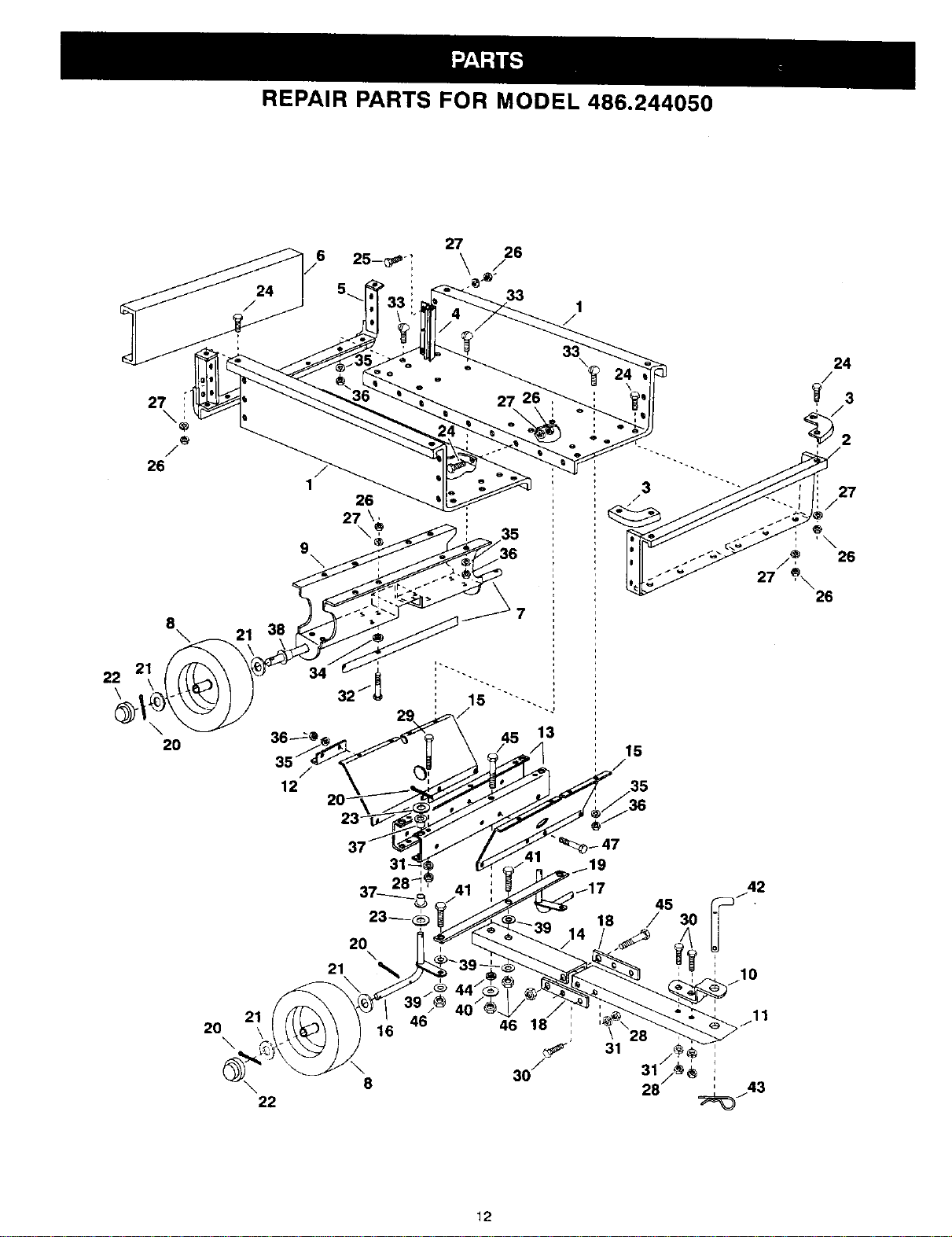
REPAIR PARTS FOR MODEL 486.244050
27
33
22
\
27
\
®
/
26
8
2
20
26
27 \_
\ _ / 35
9
\ _36
34
12
32
13
15
/
27
/
21
41
2O
\
22
\
8
46
46 18
30/
12
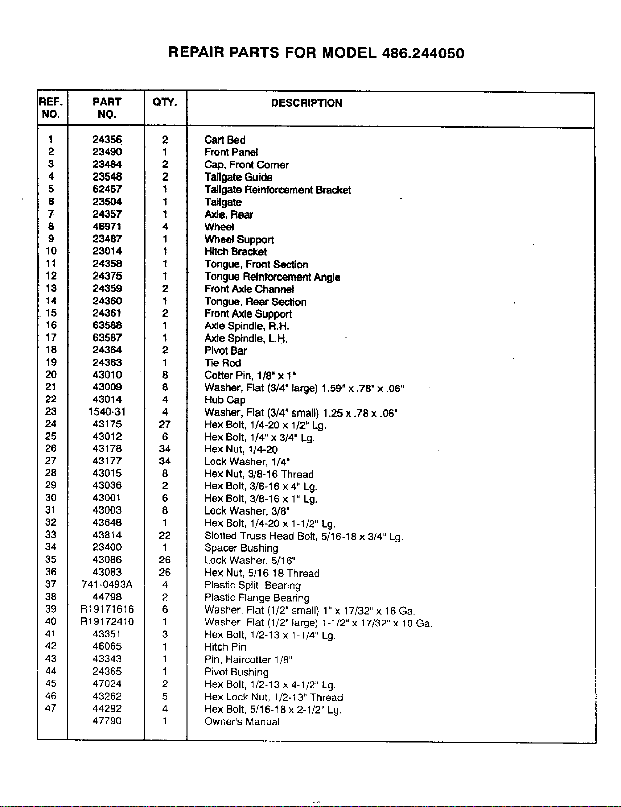
REPAIR PARTS FOR MODEL 486.244050
REF.
NO.
1
2
3
4
5
6
7
8
9
10
11
12
13
14
15
16
17
18
19
20
21
22
23
24
25
26
27
28
29
30
31
32
33
34
35
36
37
38
39
4O
41
42
43
44
45
46
47
PART
NO.
24354
23490
23484
23548
62457
23504
24357
46971
23487
23014
24358
24375
24359
24360
24361
63588
63587
24364
24363
43010
43009
43014
1540-31
43175
43012
43178
43177
43015
43036
43001
43003
43648
43814
23400
43086
43083
741-0493A
44798
R19171616
R19172410
43351
46065
43343
24365
47024
43262
44292
47790
QTY.
2
1
2
2
1
1
1
4
1
1
1
1
2
1
2
1
1
2
1
8
8
4
4
27
6
34
34
8
2
6
8
1
22
1
26
26
4
2
6
1
3
1
1
1
2
6
4
1
DESCRIPTION
Cart Bed
Front Panel
Cap, Front Comer
Tailgate Guide
Tailgate Reinforcement Bracket
Tailgate
Axle, Rear
Wheel
Wheel Support
Hitch Bracket
Tongue, Front Section
Tongue Reinforcement Angle
Front Axle Channel
Tongue, Rear Section
Front Axle Support
Axle Spindle, R.H.
Axle Spindle, L.H.
Pivot Bar
Tie Rod
Cotter Pin, 1/8" x 1"
Washer, Flat (3/4" large) 1.59" x .78" x .06"
Hub Cap
Washer, Flat (3/4" small) 1.25 x .78 x .06"
Hex Bolt, 1/4-20 x 1/2" Lg.
Hex Bolt, 1/4" x 3/4" Lg.
Hex Nut, 1/4-20
Lock Washer, 1/4"
Hex Nut, 3/8-16 Thread
Hex Bolt, 3/8-16 x 4" Lg.
Hex Bolt, 3/8-16 x 1" Lg.
Lock Washer, 3/8"
Hex Bolt, 1/4-20 x 1-1/2" Lg.
Slotted Truss Head Bolt, 5/16-18 x 3/4" Lg.
Spacer Bushing
Lock Washer, 5/! 6"
Hex Nut, 5/16-18 Thread
Plastic Split Bearing
Plastic Flange Bearing
Washer, Flat (1/2" small) 1" x 17/32" x !6 Ga.
Washer, Flat (1/2" large) 1-1/2" x 17/32" x 10 Ga.
Hex Bolt, 1/2-13 x 1-1/4" Lg.
Hitch Pin
Pin, Haircotter 1/8"
Pivot Bushing
Hex Bolt, 1/2-13 x 4-1/2" Lg.
Hex Lock Nut, 1/2-13" Thread
Hex Bolt, 5/16-18 x 2-1/2" Lg.
Owner's Manual

NOTES
14
&
CAUTION: Do not operate your tractor and cart on a slope in
excess of 10 degrees. Be sure of your tractor's towing and braking
capabilities before operating on a slope. Avoid any sudden turns
or maneuvers while on a slope.

For in-homemajor brand repair service:
Call 24 hours a day, 7 days a week
1-800-4-MY-HOME °"(1-800-469-4663)
Para pedir servicio de reparaci6n a domicilio - 1-800-676-5811
In Canada for all your service and parts needs call
- 1-800-665-4455
Au Canada pour tout le service ou les pi_ces
For the repair or replacement parts you need:
Call 7 am - 7 pro, 7 days a week
1-800-366-PART (1-800-366-7278)
Para ordenar piezas con entrega a domicilio - 1-800-659-7084
For the location of a Sears Parts and Repair Center in your area:
Call 24 hours a day, 7 clays a week
1-800-488-1222
For information on purchasing a Sears Maintenance Agreement
or to inquire about an existing Agreement:
Call 9 am - 5 pm, Monday - Saturday
1-800-827-6655
TheServiceSideofSeam"
PRINTED IN U.S.A. FORM NO. 47790 (1/00)
16