
Loading ...
Loading ...
Loading ...
EN
W415-2007 / D / 04.28.21
13
installation
3.2 installing the EPI3-1
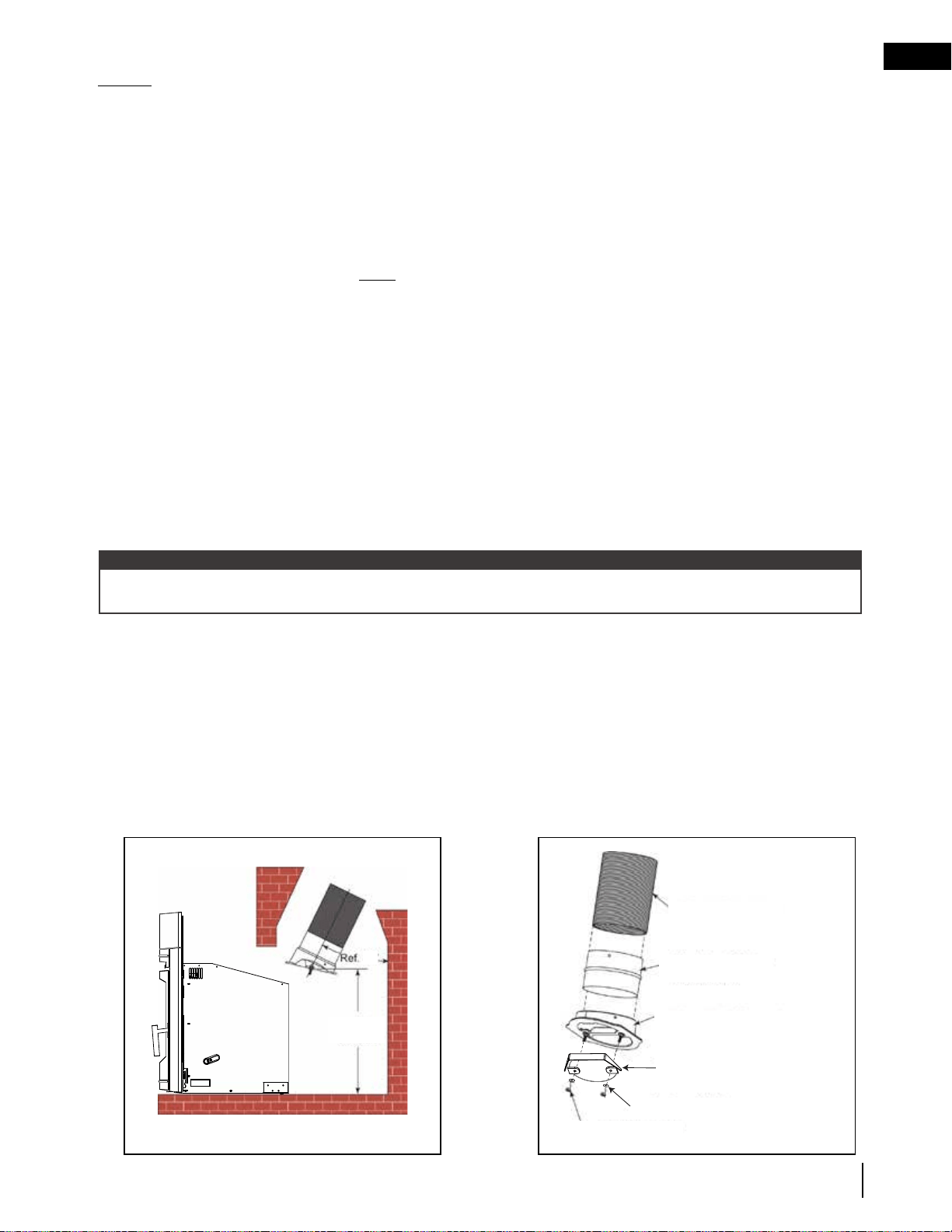
A. flue collar orientation
Prior to installation, determine the type of orientation that works best with this appliance.
The flue collar’s orientation can be vertical. It can also be a 30° backwards angle by rotating the flue collar 180° at
the top of the appliance.
It is recommended to clean the chimney from the top downwards. This will ensure that the centre bar of the flue
collar protects the inside baffle from any damages caused by the chimney brush. However, if cleaning must be
done from inside the home, use a reciprocating metal cutting saw or hack saw to cut the centre bar inside the flue
collar.
B. installing a venting system
1. Remove the front air tube to gain access to the fiber baffle, and then remove the fiber baffle.
2. Remove the iron flue collar from the appliance. Ensure gasket is in place and in good condition.
3. Drill 3 holes into the adapter pipe or flue liner, using the holes in the iron collar as a guide. Secure
the adapter pipe (or flue liner) to the flue collar. Ensure the studs on the flue collar are properly
aligned to their respective holes on the insert.
4. Repeat Step 3 to secure the flexible pipe to the pipe adaptor.
5. The finished height measurements from the hearth surface to the center bar of the flue collar should
be 19” (482.6mm). See Figure 2 for details on the installation of the connector pipe or liner. This
allows for an easy connection once the appliance is in place.
FLEXIBLE FLUE LINER
FLEX LINER ADAPTER
(IF REQUIRED)
ADJUSTABLE (30” (762mm) OR
VERTICAL) FLUE COLLAR WITH
INTEGRATED DRAW-DOWN BAR
TOP OF INSERT AROUND
FLUE OPENING
WASHERS (1/4” (6.4mm) DIAMETER)
1/4 - 20 HEX NUTS
30°
18
7
/
8
”
(479.4mm)
Fig. 1 Fig. 2
In USA: Though not required, it is recommended that a chimney liner that is continuous from the insert to
the top of the chimney be installed, particularly when the insert is installed in a basement. For this type of connection,
use the “In Canada” installation instructions above.
If a continuous liner is not installed, a “direct flue connection” must be made. The direct flue connection requires a
non-combustible connector that extends from the insert into the chimney flue liner. The installed flue cover must be
sealed below the entry point of the connector to prevent dilution of combustion products in the chimney flue. This
room heater must be connected to a code-approved masonry chimney with a flue liner. Cap the top of the chimney
using an approved rain cap.
The installation requirements that follow must be observed when installing solid fuel burning inserts into factory-built
fireplaces.
It is recommended that the connector or flue liner be installed before continuing with the installation. See
Figure 1 for venting system components.
note:
Loading ...
Loading ...
Loading ...