
®
MODEL NU 937.256541 OWNER'S MANUAL
° Assembly
° Operation
° Customer Responsibilities
Service and Adjustments
° Repair Parts
CAUTION:Read and follow all safety rules and instructions before operating this equipment.
FOR CONSUMER ASSISTANCE HOT LINE, CALL THIS TOLL FREE NUMBER: t-800-659_5917
, , i ,
SAFETY RULES
Safe Operation Practices for Ride=On Mowers
IMPORTANT: THIS CUTTING MACHINE IS CAPABLE OF AMPUTATING HANDS AND FEET AND THROWING OBJECTS
FAILURE TO OBSERVE THE FOLLOWING SAFETY INSTRUCTIONS COULD RESULT IN SERIOUS INJURY OR DEATH
1. GENERAL OPERATION
• Read, understand, and follow a]f instructions in the manual
and on the machine before starting.
• Only allow responsible adults, who are faro[tier with the
instructions, to operate the machine,
• Clear the area of objects such as rocks, toys, wire, etc,,
which could be picked up and thrown by the biade_
• Be sure the area is clear of other people before mowing Stop
machine if anyone enters the area
= Never carry passengers
• Do not mow in reverse unless absolutely necessary Always
took down and behind before and while backing,
° Be aware of the mower discharge direction and do not point
it at anyone, Do not operate the mower without either the
entire grass catcher or the guard in place
= Slow down before turning
. Never leave a running machine unattended Always turn off
blades, set parking brake, stop engine, and remove keys
before dismounting
• Turn off blades when not mowing
• Stop engine before removing grass catcher or unclogging
chute
- Mow only in daylight or good artificial light
• Do not operate the machine while under the influence of
alcohol or drugs
• Watch for traffic when operating near of crossing roadways=
• Use extra care when loading or unloading the machine into
a trailer or truck.
II. SLOPE OPERATION
Slopes are a major factor related to loss-of-control and
tipover accidents, which can result in severe injury or
death,. All slopes require extra caution. If you cannot back
up the slope or if you feel uneasy on it, do not mow it.
DO:
o Mow up and down slopes, not across
• Remove obstacles such as rocks, tree limbs, etc
• Watch for holes, ruts, or bumps: Uneven terrain could
overturn the machine Tatf grass can hide obstacles
• Use slow speed Choose a low gear so that you will not have
to stop or shift while on the slope
,, Follow the manufacturer's recommendations for wheel
weights or counterweights to improve stability.
• Use extra care with grass catchers or other attachments,,
These can change the stability of the machine,
• Keep alt movement on the slopes slow and gtaduat. Do net
make sudden changes in speed or direction.
• Avoid starting or stopping on a slope, If tires lose traction,
disengage the blades and proceed sIowly straight down the
slope
DO NOT:
= Donot turn on s]opes unless necessary, andthen, turn slowly
and gradually downhill, if possible_
° Do not mow near' drop-offs, ditches, or embankments., The
mower could suddenly turn over if a wheel is over the edge
of a cliff or ditch, or if an edge caves in.
= Do not mow on wet grass, Reduced traction could cause
sliding,
o Do not try to stabilize the machine by putting your foot on the
ground°
• Do not use grass catcher on steep slopes
IlL CHILDREN
Tragic accidents can occur if the operator is not alert to the
presence of children° Children are often attracted to the
machine and the mowing activity Never assume that
children will remain where you last saw them.
• Keep children out of the mowing area and under the watchful
care of another responsible adult
. Be aled and turn machine off if children enter the area
• Before and when backing, look behind and down for small
children
° Never carry chiIdren They may fall off and be seriously
injured or interfere with safe machine operation
• Never allow children to operate the machine.
- Use extra care when approaching blind corners, shrubs,
trees, or other objects that may obscure vision
IV. SERVICE
• Use extra care in handling gasoline and other fuels. They are
flammable and vapors are explosive
Use only an approved container
Never remove gas cap or add fuel with the engine
running Allow engine to cool before refueling Do not
smoke
Never refuel the machine indoors
Never store the machine or fuel container inside where
there is an open flame, such as a water heater,
• Never run a machine inside a closed area.
= Keep nuts and bolts, especially blade attachment bolts, tight
and keep equipment in good condition
° Never tamper with safety devices. Check their proper
operation regularly,,
° Keep machine free of grass, leaves, or other debris build-up
Clean oil or fuel spillage. Allow machine to cool before
storing
• Stop and inspect the equipment if you strike an object
Repair, if necessary, before restarting
• Never make adjustments or repairs with the engine running.
° Grasscatcher components are subject to wear, damage, and
deterioration, which could expose moving parts or allow
objects to be thrown. Frequently check components and
replace with manufacturer's recommended parts, when nec-
essary.
• Mower blades are sharp and can cut Wrap the blade(s) or
wear gloves, and useextra caution when servicing them.
o Check brake operation frequently. Adjust and service as
required.
Look for this symbol to point out important
safety precautions. It means
CAUTION!!I BECOME ALERT!!! YOUR
SAFETY IS INVOLVED.
CAUTION: Always disconnect spark plug
wire and place wire where it cannot contact
spark plug in order to prevent accidental
starting when setting up, transporting,
adjusting or making repairs°
WARNING ,&
The engine exhaust from this product contains
chemicals known to the State of California to
cause cancer, birth defects, or other reproduc-
tive harm.
i i
CONGRATULATIONS on your purchase of a Sears
Tractor, It has been designed, engineered and manufac-
tured to give you the best possible dependability and
performance.
Should you experience any problem you cannot easily
remedy, please contact your nearest Sears Authorized
Service Center/Department We have competent, well-
trained technicians and the proper tools to sewice or repair
this tractor.
Please read and retain this manual, The instructions will
enable you to assemble and maintain your tractor properly.
Always observe the "SAFETY RULES"
MODEL
NUMBER
SERIAL
NUMBER
917.256541
DATE OF PURCHASE
THE MODEL AND SERIAL NUMBERS WILL BE FOUND
ON A PLATE UNDER THE SEAT.
YOU SHOULD RECORD BOTH SERIAL NUMBER AND
DATE OF PURCHASE AND KEEP IN A SAFE PLACE
FOR FUTURE REFERENCE.
MAINTENANCE AGREEMENT
A Sears Maintenance Agreement is available on this prod-
uct. Contact your nearest Sears store for details,
CUSTOMER RESPONSIBILITIES
o Read and observe the safety rules.
• Follow a regular schedule in maintaining, caring for and
using your tractor.
• Follow the instructions under "Customer Responsibili-
ties" and "Storage" sections of this owner's manual.
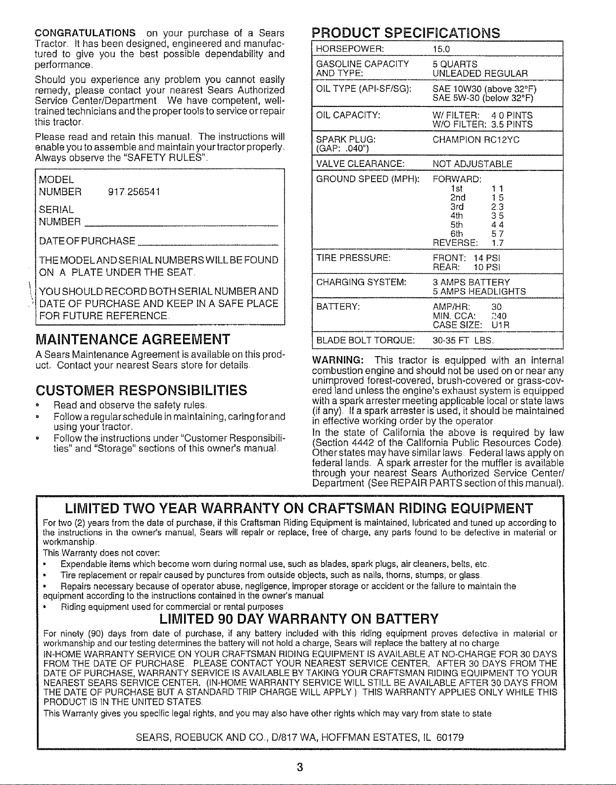
PRODUCT SPECIFDCATtONS
HORSEPOWER: 15,0
GASOLINE CAPACITY 5 QUARTS
AND TYPE: UNLEADED REGULAR
OfL TYPE (API-SF/SG): SAE 10W30 (above 32°F)
SAE 5W-30 (below 32_F)
OlL CAPACITY: Wi FILTER: 4 0 PINTS
W/O FILTER: 3.5 PINTS
SPARK PLUG: CHAMPION RC12YC
(GAP: .040")
VALVE CLEARANCE: NOT ADJUSTABLE
GROUND SPEED (MPH): FORWARD:
1st 1 1
2rid 15
3rd 23
4th 3 5
5th 4 4
6th 5 7
REVERSE: 1.7
TIRE PRESSURE: FRONT: 14 PSi
REAR: 10 PSi
CHARGING SYSTEM: 3 AMPS BATTERY
5 AMPS HEADLIGHTS
BATTERY: AMP/HR: 30
MIN. CCA: 240
CASE SIZE: U1R
BLADE BOLT TORQUE: 30-35 FT LBS
WARNING: This tractor is equipped with an internal
combustion engine and should not be used on or near any
unimproved forest-covered, brush-covered or grass-cov-
ered land unless the engine's exhaust system is equipped
with a spark arrester meeting applicable local or state laws
(if any), If a spark arrester is used, it should be maintained
in effective working order by the operator
In the state of California the above is required by law
(Section 4442 of the California Public Resources Code).
Other states may have similar laws Federal laws apply on
federal lands A spark arrester for the muffler is available
through your nearest Sears Authorized Service Center/
Department (See REPAIR PARTS section ofthis manual).
LIMITED TWO YEAR WARRANTY ON CRAFTSMAN RIDING EQUIPMENT
For two (2) years from the date of purchase, if this Craftsman Riding Equipment is maintained, lubricated and tuned up according to
the instructions in the owner's manual, Sears will repair or replace, free of charge, any parts found to be defective in material or
workmanship,
This Warranty does not cover:
• Expendable items which become worn during normal use, such as blades, spark plugs, air cleaners, belts, etc
• Tire replacement or repair caused by punctures from outside objects, such as nails, thorns, stumps, or glass
. Repairs necessary because of operator abuse, negligence, improper storage or accident or the failure to maintain the
equipment according to the instructions contained in the owner's manual
• Riding equipment used for commercia! or rental purposes
LIMITED 90 DAY WARRANTY ON BATTERY
For ninety (90) days from date of purchase, if any battery included with this riding equipment proves defective in material or
workmanship and our testing determines the battery will not hold a charge, Sears will replace the battery at no charge
IN-HOME WARRANTY SERVICE ON YOUR CRAFTSMAN RIDING EQUIPMENT IS AVAILABLE AT NO-CHARGE FOR 30 DAYS
FROM THE DATE OF PURCHASE PLEASE CONTACT YOUR NEAREST SERVICE CENTER. AFTER 30 DAYS FROM THE
DATE OF PURCHASE, WARRANTY SERVICE iS AVAILABLE BY TAKING YOUR CRAFTSMAN RIDING EQUIPMENT TO YOUR
NEAREST SEARS SERVICE CENTER. (IN-HOME WARRANTY SERVICE WILL STILL BE AVAILABLE AFTER 30 DAYS FROM
THE DATE OF PURCHASE BUT A STANDARD TRIP CHARGE WtLL APPLY ) THIS WARRANTY APPLIES ONLY WHILE THIS
PRODUCT IS IN THE UNITED STATES,
This Warranty gives you specific legat rights, and you may also have other rights which may vary from state to state
SEARS, ROEBUCK AND CO., D/817 WA, HOFFMAN ESTATES, IL 60179
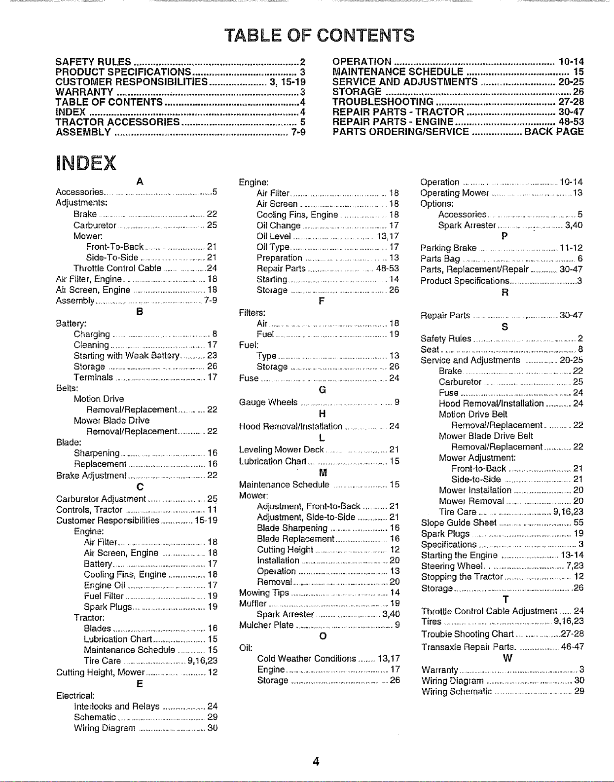
TABLE OF CONTENTS
SAFETY RULES ............................................................ 2
PRODUCT SPECIFICATIONS ...................................... 3
CUSTOMER RESPONSIBILITIES ..................... 3, 15-19
WARRANTY ................... ;.............................................. 3
TABLE OF CONTENTS ................................................. 4
INDEX ............................................................................ 4
TRACTOR ACCESSORIES .......................................... 5
ASSEMBLY ............................................................... 7-9
OPERATION .......................................................... 10-14
MAINTENANCE SCHEDULE ..................................... 15
SERVICE AND ADJUSTMENTS ........................... 20-25
STORAG E ................................................................... 26
TROUBLESHOOTING ........................................... 27-28
REPAIR PARTS - TRACTOR ................................ 30-47
REPAIR PARTS - ENGINE .................................... 48-53
PARTS ORDERING/SERVICE .................. BACK PAGE
INDEX
A
Accessodes ..................................................5
Adjustments:
Brake ...................................................22
Carburetor ........................................25
Mower:
Front-To-Back .......................... 21
Side-To-Side .......................................21
Throttle Control Cable ....................24
Air Filter, Engine .......................................18
Air Screen, Engine ................................. 18
Assembly .......................................................7-9
B
Battery:
Charging .............................................. 8
Cleaning ............................................17
Starting with Weak Battery .............23
Storage ..........................................................26
Terminals ...........................................17
Belts:
Motion Drive
Removal/Replacement ...............22
Mower Blade Drive
Removal/Replacement ...............22
Biade:
Sharpening .............................................16
Replacement .................................. 16
Brake Adjustment ..........................................22
C
Cmburetor Adjustment ................................25
Controls, Tractor ...........................................11
Customer Responsibilities ............. 15-19
Engine:
Air Filter .................................. 18
Air Screen, Engine ...........................18
Battery ............................................17
Cooling Fins, Engine ..................18
Engine Oil .......................................17
Fuel Filter .........................................19
Spark Plugs ....................................19
Tractor:
Blades ..............................................16
Lubrication Chart ...................... t 5
Maintenance Schedule ................15
Tire Care ..................................9,16,23
Cutting Height, Mower ............................ 12
E
Electrical:
Interlocks and Relays ................. 24
Schematic .........................................29
Wiring Diagram .......................... 30
Engine:
Air Filter, ...................................................18
Air Screen ............................................! 8
Cooling Fins, Engine .........................18
Oil Change ..................................................17
Oil Level ........................................13,17
Oil Type ............................................. 17
Preparation ..................................... 13
Repair Parts ......................................48-53
Starting ...............................................14
Storage ..............................................26
F
Fiffers:
Air ..................................................... 18
Fuel ...............................................................19
Fuel:
Type ................................................. 13
Storage .......................................................26
Fuse ..........................................................................24
G
Gauge Wheels ............................................. 9
H
Hood Removal/Installation ........................24
L
Leveling Mower Deck ..................... 21
Lubrication Chart .................................... 15
M
Maintenance Schedule ....................................15
Mower:
Adjustment, Front4o-Back ..............21
Adjustment, Side-to-Side ...............21
Blade Sharpening ............................... 16
Blade Replacement ........................16
Cutting Height .............................................12
Installation ................................................20
Operation ...................................... 13
Removal ..............................................20
Mowing Tips ...................................................... 14
Muffler, .........................................................I9
Spark Arrester ........................... 3,40
Mulcher Plate ......................................................9
O
Oil:
Cold Weather Conditions ....... 13,17
Engine ........................................................17
Storage ............................................ 26
Operation ................................................10-14
Operating Mower .......................................13
Options:
Accessories ...............................................5
Spark Arrester .................:................3,40
P
Parking Brake .....................................11-12
Parts Bag ...........................................................6
Parts, Replacement/Repair ..............30-47
Product Specifications ................................3
R
Repair Parts ..........................................30-47
S
Safety Rules ....................................................2
Seat ....................................................................... 8
Service and Adjustments ......................20-25
Brake ................................................................22
Carburetor ....................................................25
Fuse ........................................................24
Hood Removal/Installation .......... 24
Motion Drive Belt
RemovaVReplacement .............22
Mower Blade Drive Belt
Removal/Replacement ......... 22
Mower Adjustment:
Front-to-Back ............................ 21
Side-to-Side .....................................21
Mower Installation .......................... 20
Mower Removal ................................20
Tire Care ..................................9,16,23
Slope Guide Sheet ...................................... 55
Spark Plugs .............................................. 19
Specifications ..................................................3
Starting the Engine .............................13-14
Steedng Wheel ........................................7,23
Stopping the Tractor ............................... 12
Storage ..................................................... 26
T
Throttle Control Cable Adjustment ..... 24
Tires ............................................................9,16,23
Trouble Shooting Chart .........................27-28
Transaxle Repair Parts ......................46*47
W
Warranty ......................................................3
Wiring Diagram .............................................. 30
Wiring Schematic .....................................29
4
ACCESSO ES ANDATTACH ENTS
These accessories and attachments were available through most Sears retait outlets and service centers when the tractor was purchased
Most Sears stores can order these items for you when you provide the model number of your tractor
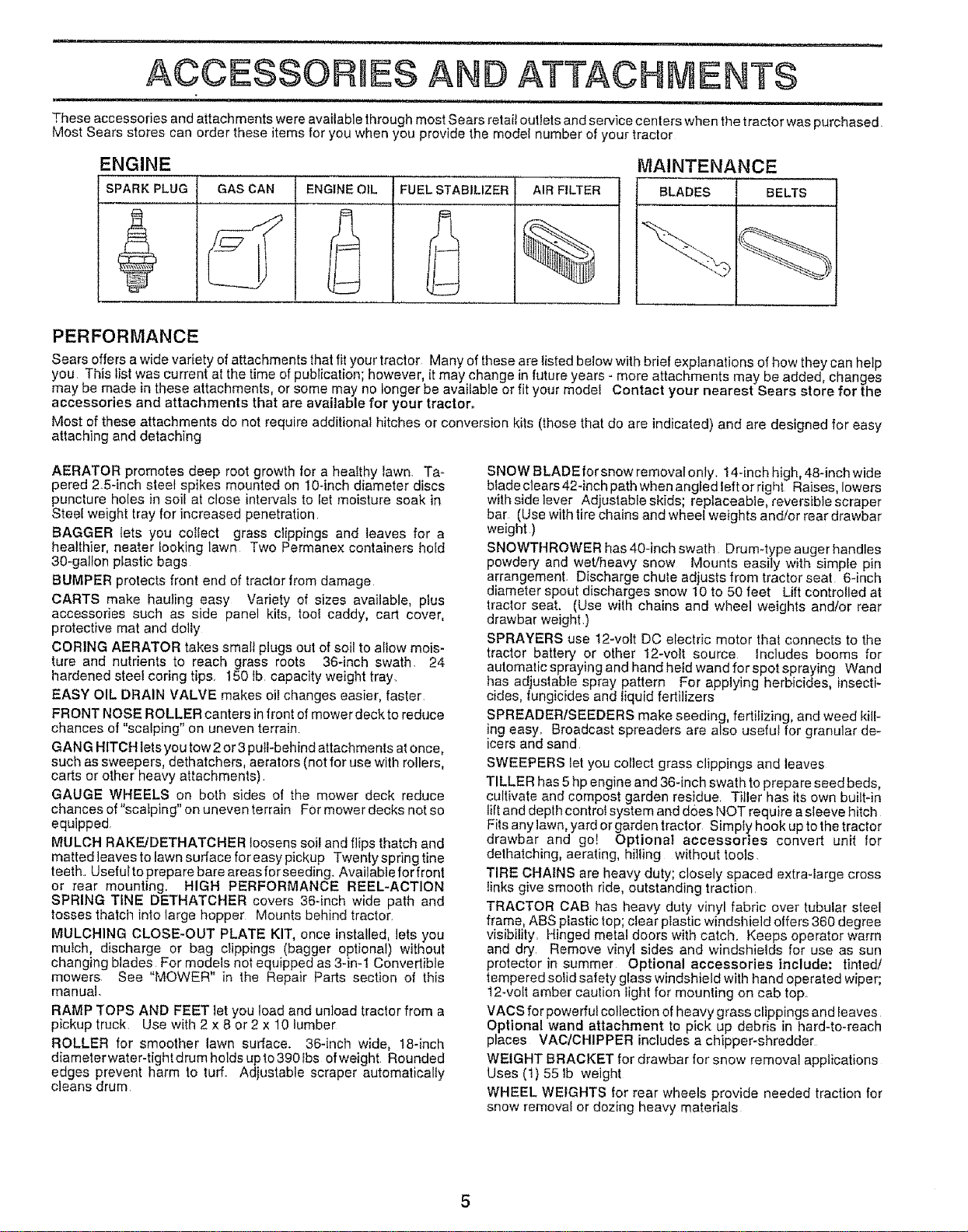
ENGINE
SPARK PLUG GAS CAN
ENGINE OIL FUEL STABILIZER AIR FILTER
%
MAINTENANCE
BLADES BELTS
PERFORMANCE
Sears offers awide variety of attachments that fit your tractor Many of these are listed below with brief explanations of how they can help
you This list was current at the time of publication; however, it may change in future years - more attachments may be added changes
may be made in these attachments, or some may no longer be avai abe or f t your model Contact your nearest Sears store for the
accessories and attachments that are available for your tractor.
Most of these attachments do not require additional hitches or conversion kits (those that do are indicated) and are designed for easy
attaching and detaching
AERATOR promotes deep root growth for a healthy lawn. Ta-
pered 2o5-inch steel spikes mounted on 10-inch diameter discs
puncture holes in soil at close intervals to let moisture soak in
Steel weight tray for increased penetration.
BAGGER lets you collect grass clippings and leaves for a
healthier, heater looking lawn Two Permanex containers hold
30-gallon plastic bags
BUMPER protects front end of tractor from damage
CARTS make hauling easy Variety of sizes available, plus
accessories such as side panel kits, tool caddy, cad cover,
protective mat and dolly
CORING AERATOR takes small plugs out of soil to allow mois-
ture and nutrients to reach grass roots 36-inch swath. 24
hardened steel coring tips. t50 tb capacity weight tray.
EASY OIL DRAIN VALVE makes oil changes easier, faster.
FRONT NOSE ROLLER canters infront of mower deck to reduce
chances of "scalping" on uneven terrain.
GANG HITCH lets you tow 2or 3 pull-behind attachments at once,
such as sweepers, dethatchers, aerators (not for use with rollers,
carts or other heavy attachments)
GAUGE WHEELS on both sides of the mower deck reduce
chances of "scalping" on uneven terrain F0r mower decks not so
equipped,
MULCH RAKEJDETHATCHER loosens soil and flips thatch and
matted leaves to lawn surface for easy pickup Twenty spring tine
teeth.. Useful to prepare bare areas for seeding. Available for front
or rear mounting. HIGH PERFORMANCE REEL-ACTION
SPRING TtNE DETHATCHER covers 36-inch wide path and
tosses thatch into large hopper Mounts behind tractor.
MULCHING CLOSE-OUT PLATE KIT, once installed, lets you
mulch, discharge or bag clippings (bagger optional) without
changing blades For models not equipped as 3-in-1 Convertible
mowers See "MOWER" in the Repair Parts section of this
manual.
RAMP TOPS AND FEET let you load and unload tractor from a
pickup truck. Use with 2 x 8 or 2 x 10 lumber
ROLLER for smoother lawn surface. 36-inch wide, 18-inch
diameterwater-tightdrumholdsupto390Ibs ofweight Rounded
edges prevent harm to turf Adjustable scraper automatically
cleans drum
SNOW BLADE for snow removal only. 14-inch high, 48-inch wide
bfade clears 42-inch path when angled teft or right Raises, lowers
with side lever Adjustable skids; replaceable, reversible scraper
bar (Use with tire chains and wheeI weights and/or rear drawbar
weight )
SNOWTHROWER has 40-inch swath Drum-type auger handles
powdery and wet/heavy snow Mounts easily with simple pin
arrangement. Discharge chute adjusts from tractor seat 6-inch
diameter spout discharges snow 10 to 50 feet Lift controlled at
tractor seat. (Use with chains and wheel weights and!or rear
drawbar weight )
SPRAYERS use 12-volt DC electric motor that connects to the
tractor battery or other 12-volt source Includes booms for
automatic spraying and hand held wand for spot spraying Wand
has adjustable spray pattern For applying herbicides, insecti-
cides, fungicides and liquid fertilizers
SPREADERISEEDERS make seeding, fertilizing, and weed kill-
ing easy. Broadcast spreaders are also useful for granular de-
icers and sand
SWEEPERS let you collect grass clippings and leaves
TILLER has 5hp engine and 36-[nch swath to prepare seed beds,
cultivate and compost garden residue. Tiller has its own built-in
lift and depth controt system and does NOT require asleeve hitch
Fits any lawn, yard or garden tractor Simply hook up to the tractor
drawbar and go! Optional accessories convert unit for
dethatching, aerating, hilling without tools
TIRE CHAINS are heavy duty; closely spaced extra-large cross
links give smooth ride, outstanding traction
TRACTOR CAB has heavy duty vinyl fabric over tubular steel
frame, ABS plastic top; ctear plastic windshield offers 360 degree
visibility. Hinged metal doors with catch. Keeps operator warm
and dry Remove vinyl sides and windshields for use as sun
protector in summer Optional accessories include; tinted!
tempered solid safety glass windshield with hand operated wiper;
12-volt amber caution Iight for mounting on cab top°
VACS for powerful collection of heavy grass clippings and leaves
Optional wand attachment to pick up debris in hard-to-reach
places VAC/CHIPPER includes a chipper-shredder
WEIGHT BRACKET for drawbar for snow removal applications
Uses (t) 55 Ib weight
WHEEL WEIGHTS for rear wheels provide needed traction for
snow removal or dozing heavy materials
i -- -- =
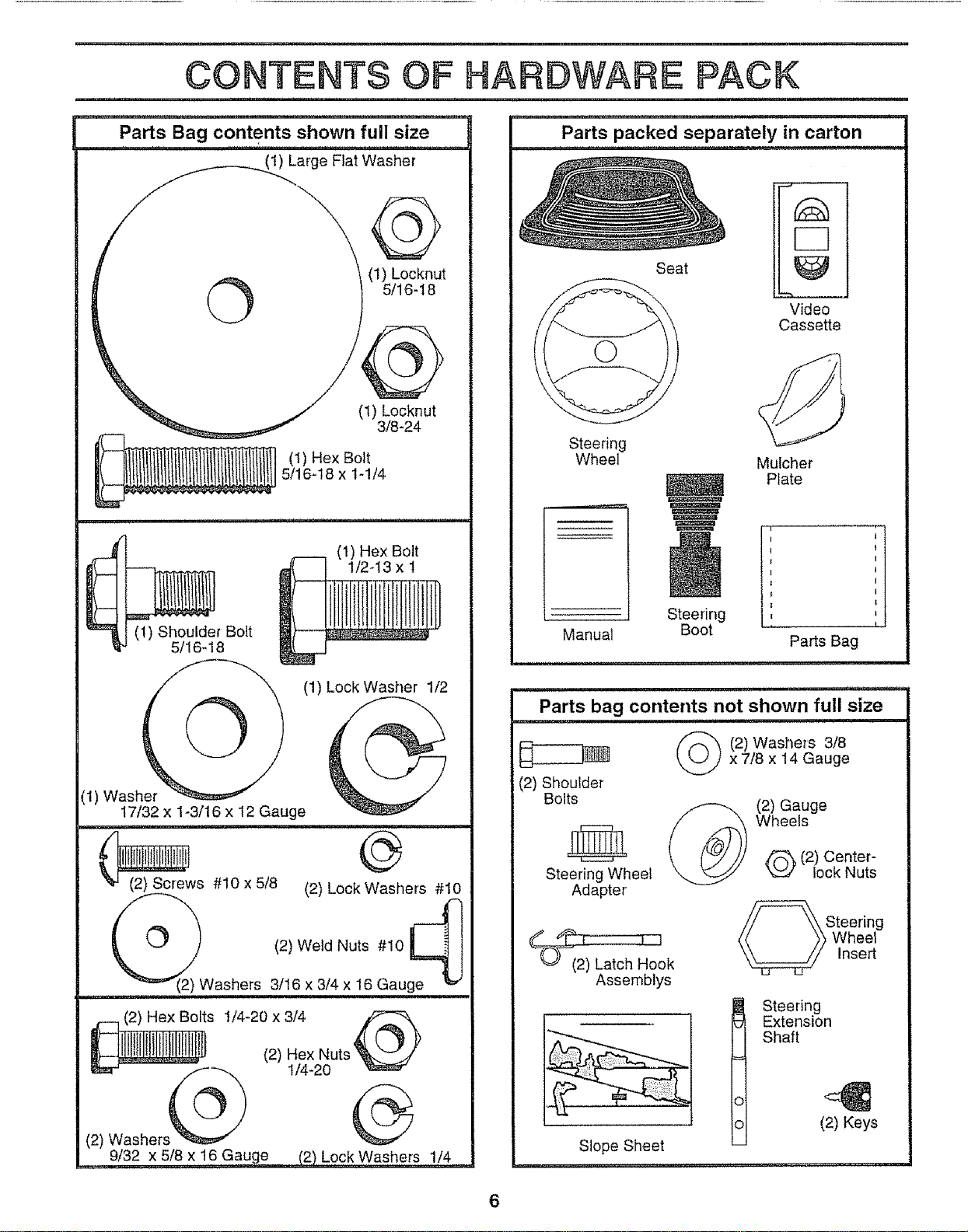
CONTENTS OF HARDWARE PACK
Parts Bag contents shown full size
1) Large Flat Washer
©
(1) Locknut
5/16-18
(1) Locknut
3/8-24
(1) Hex Bolt
5/16-18 x t-1/4
J
m
l
(1) Shoulder Bolt
5/16-18
(1) Hex Bolt
_ N N _
(1) Lock Washer 1/2
(1) Washer
17/32 x 1-3/16 x 12 Gauge
o
#10 x 5/8 (2) Lock Washers #10
.........._(2) Washers
(2) Weld Nuts #10 _ I
,RJ
3/16 x 3/4 x 16 Gauge
, ix ut,@
O "
(2) Washers@
__ 9/32 x 5/8 x16 Gauge (2) Lock Washers 1/4
Parts packed separately in carton
Seat
Video
Cassette
Steering
Wheel
Mulcher
Plate
Manual
Steering
Boot
Parts Bag
(2) Shoulder
Bolts
Steering Wheel
Adapter
Parts bag contents not shown full size
2) Washers 318
x 7/8 x 14 Gauge
_ok
Assemblys
Slope Sheet
(2) Gauge
Wheels
Q(2) Center-
lock Nuts
,,_'k_!Swteering
heel
Insert
I teering
Extension
Shaft
(2) Keys
6
ASSEMBLY
i l i i iH,i i,, i i lllll ,mmll,l l ,, ,,m ...................
Your new tractor has been assembled at the factory with exception of those parts left unassembled for shipping purposes.
To ensure safe and proper operation of your tractor all parts and hardware you assemble must be tightened securely. Use
the correct tools as necessary to insure proper tightness,
TOOLS REQUIRED FOR ASSEMBLY
A socket wrench set will make assembly easier Standard
wrench sizes are listed.
(1) 5/16" wrench (1) 3/4" Socket w/drive rachet
(2) 7/16" wrenches Phillips Screwdriver
(1) 112" wrench Tire pressure gauge
(1) 9/16" wrench Utility knife
When right or left hand is mentioned in this manual, it
means when you are in the operating position (seated
behind the steering wheel)
TO REMOVE TRACTOR FROM CARTON
UNPACK CARTON
• Remove all accessible loose parts and parts cartons
from carton (See page 6),
- Cut, from top to bottom, along lines on all four corners
of carton, and lay panels flat.
o Check for any additional loose parts or cartons and
remove.
BEFORE ROLLING TRACTOR OFF SKID
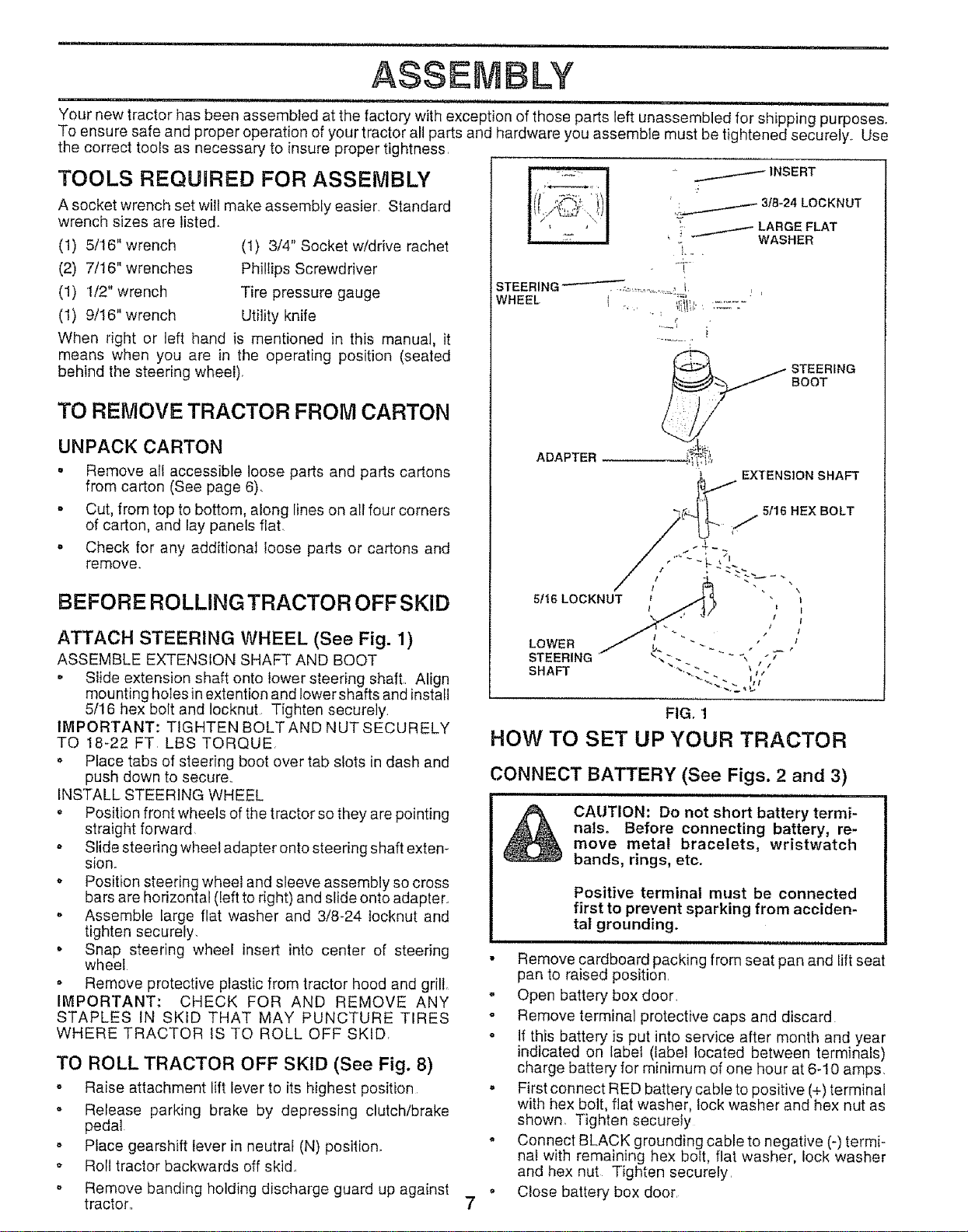
ATTACH STEERING WHEEL (See Fig. 1)
ASSEMBLE EXTENSION SHAFT AND BOOT
o Slide extension shaft onto lower steering shaft.. Align
mounting holes in extention and lower shafts and install
5/16 hex bolt and Iocknut Tighten securely.
IMPORTANT: TIGHTEN BOLT AND NUT SECURELY
TQ 18-22 FT. LBS TORQUE,
• Place tabs of steering boot over tab slots in dash and
push down to secure,.
INSTALL STEERING WHEEL
o Position front wheels of the tractor so they are pointing
straight forward
o Slide steering wheel adapter onto steering shaft extem
stono
. Position steering wheel and sleeve assembly so cross
bars are horizontal (left to right) and slide onto adapter°
o Assemble large flat washer and 3/8-24 tocknut and
tighten securely.
• Snap steering wheel insert into center of steering
wheel
o Remove protective plastic from tractor hood and grill
IMPORTANT: CHECK FOR AND REMOVE ANY
STAPLES IN SKID THAT MAY PUNCTURE TIRES
WHERE TRACTOR IS TO ROLL OFF SKID
TO ROLL TRACTOR OFF SKID (See Fig. 8)
o Raise attachment lift lever to its highest position
o Release parking brake by depressing clutch/brake
pedal
o Place gearshift lever in neutral (N) position,
,' Roll tractor backwards off skid.,
o Remove banding holding discharge guard up against
tractor.. 7
FIG, 1
HOW TO SET UP YOUR TRACTOR
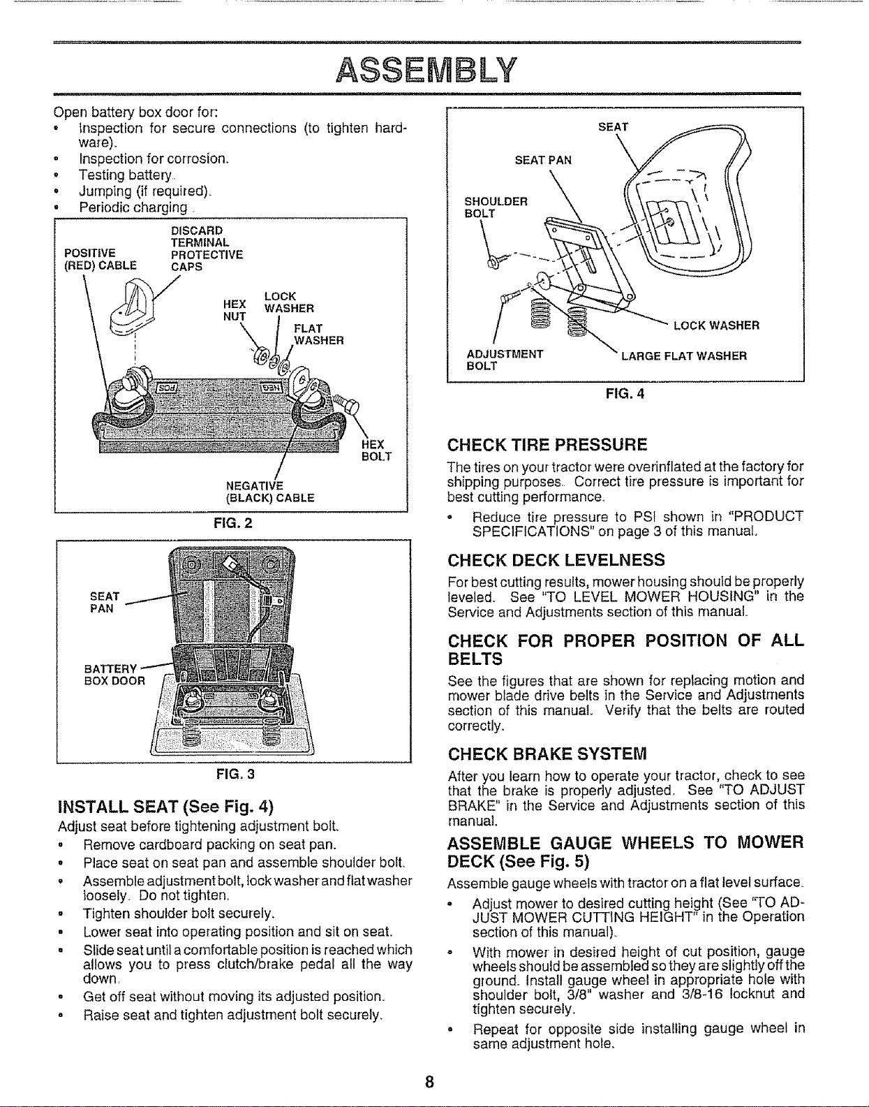
CONNECT BATTERY (See Figs. 2 and 3)
&
CAUTION: Do not short battery termi-
nals. Before connecting battery, re-
move metal bracelets, wristwatch
bands, rings, etc.
Positive terminal must be connected
first to prevent sparking from acciden-
tal grounding.
• Remove cardboard packing from seat pan and lift seat
pan to raised position
o Open battery box door.
o Remove terminal protective caps and discard
o If this battery is put into service after month and year
indicated on label (label located between terminals)
charge battery for minimum of one hour at 6-10 amps.
o First connect RED battery cable to positive (+) terminal
with hex bolt, flat washer, lock washer and hex nut as
shown Tighten securely
o Connect BLACK grounding cable to negative (-) termi-
na! with remaining hex bolt, flat washer, lock washer
and hex nut Tighten securely
= Close battery box door
ASS
Open battery box doer for':
. Inspection for' secure connections (to tighten hard-
LY
ware)_
. Inspection for corrosion,
° Testing battery
o Jumping (if required),
° Periodic charging
DISCARD
TERMINAL
POSITIVE PROTECTIVE
(RED) CABLE CAPS
HEX
NUT
LOCK
WASHER
FLAT
WASHER
!
NEGATIVE
(SLACK) CABLE
FIG. 2
SEAT
PAN
BATTER _
BOX DOOR
FIG, 3
INSTALL SEAT (See Fig. 4)
Adjust seat before tightening adjustment boil
= Remove cardboard packing on seat pan.
SEAT PAN
HEX
BOLT
SHOULDER
BOLT
ADJUSTMENT
BOLT
SEAT
LOCK WASHER
LARGE FLAT WASHER
The tires on your tractor were ovednflated at the factory for
shipping purposes. Correct tire pressure is important for
best cutting performance.
o Reduce tire pressure to PSI shown in "PRODUCT
SPECIFICATIONS" on page 3 of this manual.
CHECK DECK LEVELNESS
For best cutting results, mower housing should be properly
leveled. See "TO LEVEL MOWER HOUSING" in the
Service and Adjustments section of this manual°
CHECK FOR PROPER POSITION OF ALL
BELTS
See the figures that are shown for reptacing motion and
mower blade drive belts in the Service and Adjustments
section of this manual Verify that the belts are routed
correctly.
CHECK BRAKE SYSTEM
After you learn how to operate your' tractor, check to see
that the brake is properly adjusted, See "TO ADJUST
BRAKE" in the Service and Adjustments section of this
manual
ASSEMBLE GAUGE WHEELS TO MOWER
° Place seat on seat pan and assemble shoulder' boll
. Assemble adjustment bolt, lock washer and flat washer
loosely. Do not tighten_
• Tighten shoulder bolt securely.
• Lower seat intooperating position and sit on seat.
. Slide seat until a comfortable position is reached which
allows you to press clutch/brake pedal all the way
down,
• Get off seat without moving its adjusted position.
° Raise seat and tighten adjustment bolt securely,
DECK (See Fig. 5)
Assemble gauge wheels with tractor on a flat level surface.
• Adjust mower' to desff'ed cutting height (See 'q-o AD-
JUST MOWER CUTTING HEIGHT" in the Operation
section of this manual).
- With mower in desired height of cut position, gauge
wheels should be assembled so they are slightly off the
ground. Install gauge wheel in appropriate hole with
shoulder bolt, 3/8" washer and 3/8-16 Iocknut and
tighten securely.
- Repeat for opposite side installing gauge wheel in
same adjustment hole..
CHECK TIRE PRESSURE
FIG. 4
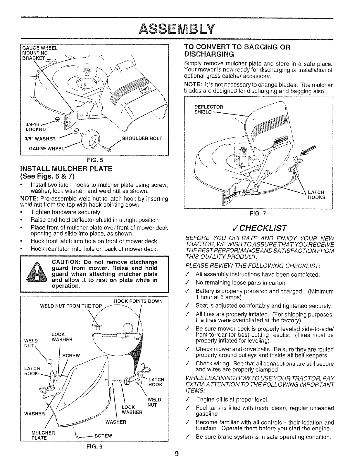
GAUGE WHEEL
MOUNTING
LOCKNUT
318" WASHER
GAUGE WHEEL'
ASSEMBLY
,,i,,,i,,llm i i,i ill ,ll
TO CONVERT TO BAGGING OR
DISCHARGING
Simply remove mulcher plate and store in a sate place.
Your mower is now ready for discharging or installation of
optional grass catcher accessory,
NOTE: Itis not necessary to change blades° The mulcher
blades are designed for discharging and bagging also.
SHOULDER BOLT
FIG. 5
INSTALL MULCHER PLATE
(See Figs, 6 & 7)
• install two latch hooks to mutcher plate using screw,
washer, lock washer, and we}d nut as shown
NOTE: Pre-assemble weld nut to latch hook by inserting
weld nut from the top with hook pointing down.
= Tighten hardware securely,
° Raise and hold deflector shield in upright position
. Place front of mulcher plate over front of mower deck
opening and slide into place, as shown..
° Hook front latch into hole on front of mower deck
= Hook rear latch into hole on back of mower deck
CAUTION: Do not remove discharge
guard from mower, Raise and hold
guard when attaching mulcher plate
and allow it to rest on plate while in
operation.
WELD NUT FROM THE TOP
LOCK
WELD WASHER
NUT _ SCREW
LATCH
WASHER
HOOK POINTS DOWN
LOCK
WASHER
WASHER
__-...--_SCREW
HOOK
WELD
NUT
FIG, 6
MULCHER
PLATE
DEFLECTOR
SHIELD
LATCH
HOOKS
FIG, 7
,/CHECKL IS T
BEFORE YOU OPERATE AND ENJOY YOUR NEW
TRACTOR, WE WISH TO ASSURE THAT YOU RECEIVE
THE BEST PERFORMANCEAND SA TISFA CTION FROM
THIS QUALITY PRODUCT
PLEASE REWEW THE FOLLOWING CHECKLIST"
v" All assembly instructions have been completed..
,,/ No remaining loose parts in carton.
v" Battery is properly prepared and charged.. (Minimum
1 hour at 6 amps)
,/ Seat is adjusted comfortably and tightened securely.
¢" Al! tires are properly inflated. (For shipping purposes,
the tires were overinflated at the factory).
¢" Be sure mower deck is properly leveled side-to-side/
front-to-rear for best cutting results. (Tires must be
properly inflated for leveling)
v" Check mower and drive belts. Be sure they are routed
properly around pulleys and inside all belt keepers
,/ Check wiring. See that all connections are still secure
and wires are properly clamped.
WHILE LEARNING HOWTO USE YOUR TRACTOR, PAY
EXTRA A TTENTION TO THE FOLL OWING IMPORTANT
ITEMS.:
v" Engine oil is at proper level
,/ Fuel tank is filled with fresh, clean, regular unleaded
gasoline..
,/ Become familiar with at! controls - their location and
function. Operate them before you start the engine
,/ Be sure brake system is in safe operating condition..
9
OPERATION
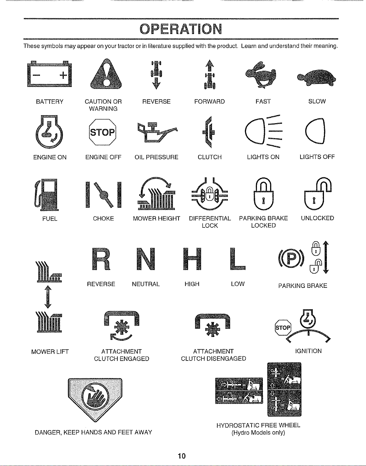
These symbols may appear on your tracto_ or in literature supplied with the product,. Learn and understand their meaning.
BATTERY CAUTION OR REVERSE FORWARD FAST SLOW
WARNING
ENGINE ON ENGINE OFF OIL PRESSURE CLUTCH LIGHTS ON LIGHTS OFF
FUEL CHOKE MOWER HEIGHT DIFFERENTIAL PARKING BRAKE UNLOCKED
LOCK LOCKED
MOWER LIFT
REVERSE NEUTRAL
ATTACHMENT
CLUTCH ENGAGED
L
HIGH LOW
÷
ATTACHMENT
CLUTCH DISENGAGED
PARKING BRAKE
IGNITION
DANGER, KEEP HANDS AND FEET AWAY
HYDROSTATIC FREE WHEEL
(Hydro Models only)
10
OPERATBON
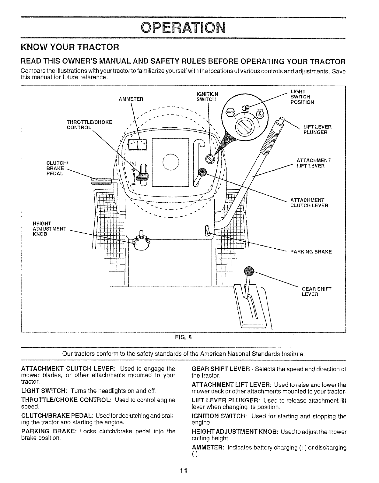
KNOW YOUR TRACTOR
READ THIS OWNER'S MANUAL AND SAFETY RULES BEFORE OPERATING YOUR TRACTOR
Compare the illustrations with your tractor to familiarize yourself with the locations of vadous controls and adjustments., Save
this manual for future reference,
THROTTLE/CHOKE
CONTROL
IGNITION LIGHT
AMMETER SWITCH SWITCH
POSITION
r, ",
/
LIFT LEVER
PLUNGER
CLUTCH/
BRAKE
PEDAL
ATTACHMENT
L1FTLEVER
HEIGHT
ADJUSTMENT
KNOB
ATTACHMENT
CLUTCH LEVER
PARKING BRAKE
GEARSHIFT
LEVER
FIG. 8
Our tractors conform to the safety standards of the American National Standards Institute
ATTACHMENT CLUTCH LEVER: Used to engage the
mower blades, or other attachments mounted to your
tractor,
LIGHT SWITCH: Turns the headlights on and off,
THROTTLE/CHOKE CONTROL: Used to control engine
speed,
CLUTCH/BRAKE PEDAL: Used for dectutching and brak-
ing the tractor and starting the engine
PARKING BRAKE: Locks clutch!brake pedal into the
brake position
GEAR SHIFT LEVER - Selects the speed and direction of
the tractor
ATTACHMENT LIFT LEVER: Used to raise and lower the
mower deck or other attachments mounted to your tractor,
LIFT LEVER PLUNGER: Used to release attachment lift
lever when changing its position,,
IGNITION SWITCH: Used for starting and stopping the
engine.
HEIGHTADJUSTMENT KNOB: Used to adjust the mower
cutting height,
AMMETER: Indicates battery charging (+) or discharging
(-)
11
OPEIRATIO
The operation of any tractor can result in foreign objects thrown into the eyes, which can
result in severe eye damage. Always wear safety glasses or eye shields while operating your
tractor or performing any adjustments or repairs. We recommend a wide vision safety mask
over the spectacles or standard safety glasses.
HOW TO USE YOUR TRACTOR
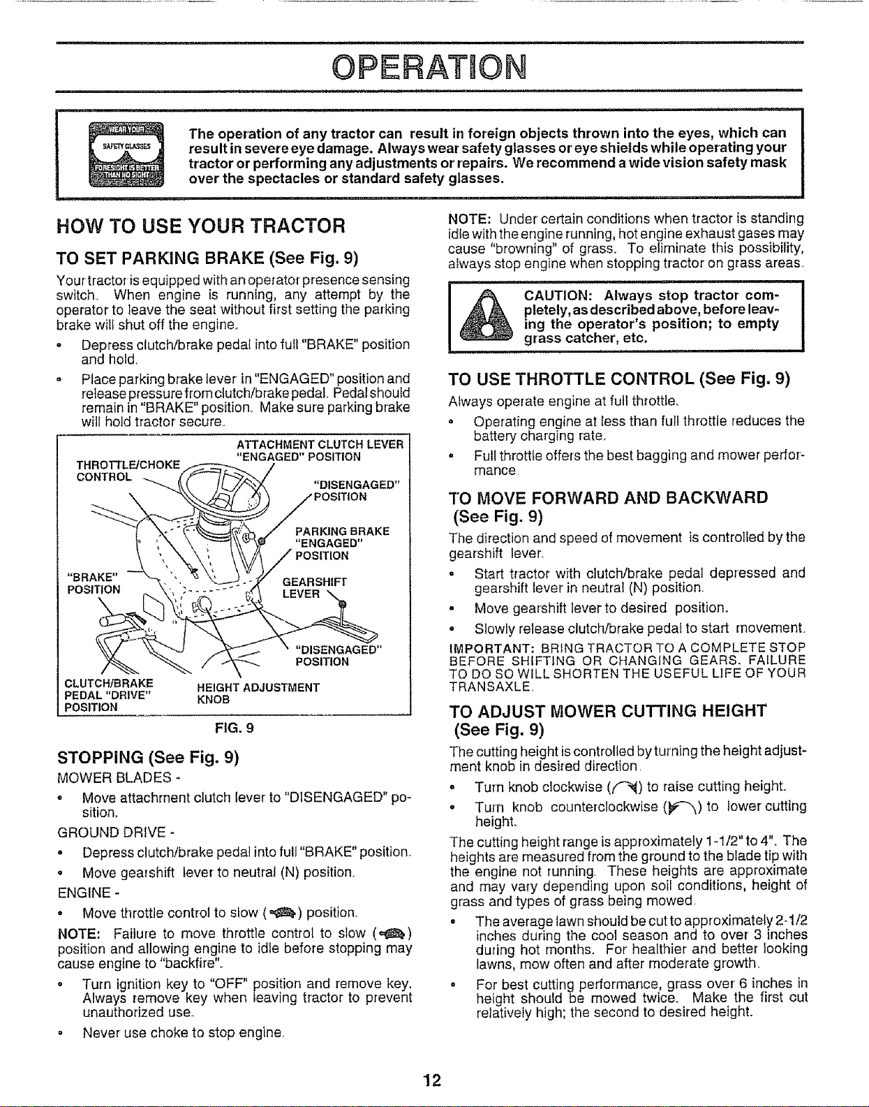
TO SET PARKING BRAKE (See Fig. 9)
Yourtractor isequipped with an operator presence sensing
switch. When engine is running, any attempt by the
operator to leave the seat without first setting the parking
brake will shut off the engine.,
• Depress clutch/brake pedal into full "BRAKE" position
and hold.
o Place parking brake lever in "ENGAGED" position and
release pressure fromclutch/brake pedal.. Pedal should
remain in"BRAKE" position_ Make sure parking brake
will hold tractor secure.
THROTTLIFJCHOKE
CONTROL
ATTACHMENT CLUTCH LEVER
"ENGAGED" POSITION
"DISENGAGED"
PARKING BRAKE
"ENGAGED"
"BRAKE" GEARSHIFI r
POSITION
"DISENGAGED"
POSITION
CLUTCHIBRAKE HEIGHT ADJUSTMENT
PEDAL"DRIVE" KNOB
POSITION
FIG. 9
STOPPING (See Fig. 9)
MOWER BLADES -
= Move attachment clutch lever to "DISENGAGED" po-
sition,.
GROUND DRIVE -
• Depress clutch/brake pedal into full "BRAKE" position.
• Move gearshift lever to neutral (N) position.
ENGINE -
o Move throttle control to stow ('_) position.
NOTE: Failure to move throttle control to slow (_,)
position and allowing engine to idle before stopping may
cause engine to "backfire".
. Turn ignition key to "OFF" position and remove key.
Always remove key when leaving tractor to prevent
unauthorized use,,
° Never use choke to stop engine.
NOTE: Under certain conditions when tractor is standing
idle with the engine running, hot engine exhaust gases may
cause "browning" of grass. To eliminate this possibility,
always stop engine when stopping tractor on grass areas
CAUTION: Always stop tractor com-
pletely, as described above, before leav-
ing the operator's position; to empty
grass catcher, etc.
TO USE THROTTLE CONTROL (See Fig, 9)
Always operate engine at full throttle_
• Operating engine at less than full throttle reduces the
battery charging rate.
. Full throttle offers the best bagging and mower perfor-
mance
3"0 MOVE FORWARD AND BACKWARD
(See Fig. 9)
The direction and speed of movement is controlled by the
gearshift lever
. Start tractor with clutch/brake pedal depressed and
gearshift lever in neutral (N) position
- Move gearshift lever to desired position.
- Slowly release clutch/brake pedal to start movement,
IMPORTANT: BRING TRACTOR TO A COMPLETE STOP
BEFORE SHIFTING OR CHANGING GEARS. FAILURE
TO DO SO WILL SHORTEN THE USEFUL LIFE OF YOUR
TRANSAXLE
TO ADJUST MOWER CUTTING HEIGHT
(See Fig. 9)
The cutting height iscontrolled by turning the height adjust-
merit knob in desired direction,
o Turn knob clockwise ((_'-_) to raise cutting height.
o Turn knob counterclockwise (_#'-"0 to lower cutting
heighL
The cutting height range is approximately 1-1/2" to 4". The
heights are measured from the ground to the blade tip with
the engine not running, These heights are approximate
and may vary depending upon soil conditions, height of
grass and types of grass being mowed,
o The average lawn should be cut to approximately 2-1/2
inches during the cool season and to over3 inches
during hot months. For' healthier and better looking
lawns, mow often and after moderate growth,
° For best cutting performance, grass over' 6 inches in
height should be mowed twice. Make the first cut
relatively high; the second to desired height.
12
OPERATION
m,, ill
,m, i ,,m i, ,i
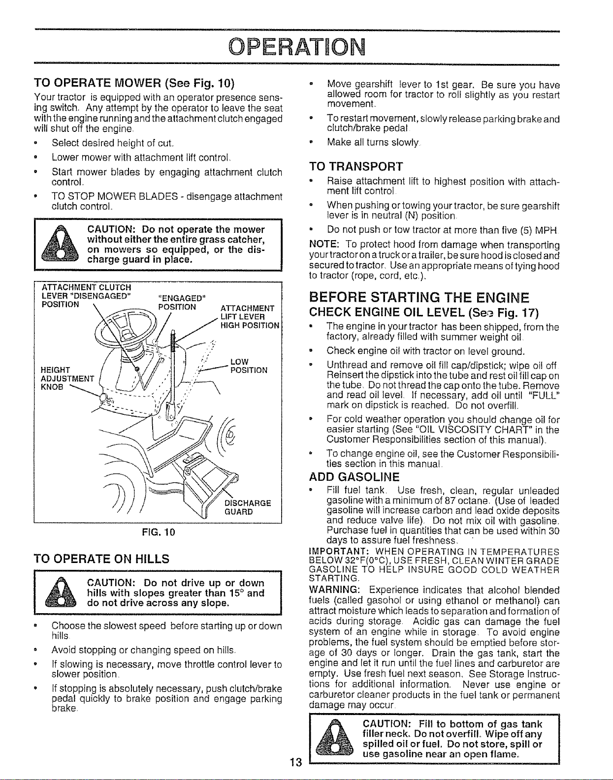
TO OPERATE MOWER (See Fig. 10)
Your tractor is equipped with an operator presence sens-
ing switch, Any attempt by the operator to leave the seat
with the engine running and the attachment clutch engaged °
wi!l shut off the engine,
= Select desired height of cut,, °
o Lower mower with attachment liftcontrol,
• Start mower blades by engaging attachment clutch
control°
• TO STOP MOWER BLADES - disengage attachment
clutch control,,
&
CAUTION: Do not operate the mower
without either the entire grass catcher,
on mowers so equipped, or the dis-
charge guard in place.
i
FIG, 10
TO OPERATE ON HILLS
tA !
CAUTION: Do not drive up or down
hills with slopes greater than 15° and
do not drive across any slope,
, Choose the slowest speed before starting up or down
hills
• Avoid stopping or changing speed on hills°
o If slowing is necessary, move throttle control lever to
slower position
° If stopping is absolutely necessary, push clutch/brake
pedal quickly to brake position and engage parking
brake.
Move gearshift lever to 1st gear. Be sure you have
allowed room for tractor to roll slightly as you restart
movement,
To restart movement, slowly release parking brake and
clutch/brake pedal
Make all turns slowly
13
TO TRANSPORT
o Raise attachment lift to highest position with attach-
ment fft control
° When pushing or towing your tractor, be sure gearshift
lever is in neutral (N) position
= Do not push or tow tractor at more than five (5) MPH
NOTE: To protect hood from damage when transporting
your tractor on a truck or a trailer, be sure hood isclosed and
secured totractor. Use an appropriate means of tying hood
to tractor (rope, cord, etc,).
BEFORE STARTING THE ENGINE
CHECK ENGINE OIL LEVEL (See Fig. '17)
. The engine in your tractor has been shipped, from the
factory, already filed with summer weight oil
° Check engine oil with tractor on level ground°
° Unthread and remove oif fill cap/dipstick; wipe oil off
Reinsert the dipstick into the tube and rest oil fill cap on
the tube. Do net thread the cap onto the tube. Remove
and read oil Ievel if necessary, add oil until "FULL"
mark on dipstick is reached. Do not overfill.
• For cold weather operation you should change oil for
easier starting (See "OIL VISCOSITY CHART" in the
Customer Responsibilities section of this manual).,
° To change engine oi!, see the Customer Responsibili-
ties section in this manuat
ADD GASOLINE
o Fill fuel tank Use fresh, clean, regular unleaded
gasoline with a minimum of 87 octane. (Use of leaded
gasoline will increase carbon and lead oxide deposits
and reduce valve life), Do not mix oil with gasoline,
Purchase fuel in quantities that can be used within 30
days to assure fuel freshness.
IMPORTANT: WHEN OPERATING IN TEMPERATURES
BELOW 32°F(0°0), USE FRESH, CLEAN WINTER GRADE
GASOLINE TO HELP INSURE GOOD COLD WEATHER
STARTING,
WARNING: Experience indicates that alcohol blended
fuels (called gasohoI or using ethanol or methanol) can
attract moisture which leads to separation and formation of
acids during storage. Acidic gas can damage the fuel
system of an engine while in storage, To avoid engine
problems, the fuel system should be emptied before stor-
age of 30 days or longer. Drain the gas tank, start the
engine and let it run until the fuel lines and carburetor are
empty. Use fresh fuel next season, See Storage Instruc-
tions for additional information. Never use engine or
carburetor cleaner products in the fuel tank or permanent
damage may occur
CAUTION: Fill to bottom of gas tank
filler neck, Do not overfill. Wipe off any
spilled oil or fuel. Do not store, spill or
use gasoline near an open flame.
OPERATHON
TO START ENGINE (See Fig. 9)
This engine on this product is designed for maximum
performance and life if operated with the choke (I\J) fully
open and the throttle control in the fast (,_) position_ To
open the choke fully requires an engine warm-up period of
several seconds to several minutes, depending on the
temperature.
After starting the engine, first open the choke slowly until
the engine just begins to run smoothly_ Then open the
choke in small steps, allowing the engine to accept small
changes in speed and toad, until the choke is fully open
During engine warm-up, the equipment can be operated.
When starting engine for the first time or if engine has run
out of fuel, it will take extra cranking time to move fuel from
the tank to the engine_
• Depress clutch/brake pedal and set parking brake_
• Piece gearshift fever in neutral (N) position..
• Move attachment clutch to "DISENGAGED" position.
• Move throttle control lever to choke ( \ ) position for
co d eng ne start. For warm engine start, move throttle
control to fast (,_) position.
. Insert key into ignition and turn key clockwise to"START"
position and release key as soon as engine starts. Do
not run starter continuously for' more than fifteen
seconds per minute If engine does not start after
several attempts, move throttle control to fast ('_)
position, wait a few minutes and try again_
° When engine starts, move throttle control to desired
position.
° Mow engine to warm up for a few minutes before
engaging drive or attachments.
NOTE: If at a high altitude (above 3000 feet) or in coid
temperatures (below 32°F), the carburetor fuel mixture
may need to be adjusted for' best engine performance° See
'q'O ADJUST CARBURETOR" in the Service and Adjust-
ments section of this rnanuai.
MOWING TIPS
. Tire chains cannot be used when the mower housing
is attached to t_actoro
• Mower should be properly leveled for best mowing
performance. See"TO LEVEL MOWER HOUSING"in
the Service and Adjustments section of this manual.
. The left hand side of mower should be used for trim-
ming
• Drive so that clippings are discharged onto the area
that has been cut. Have the cut aiea to the right of the
machine._ This will result in a more even distribution of
clippings and more uniform cutting_
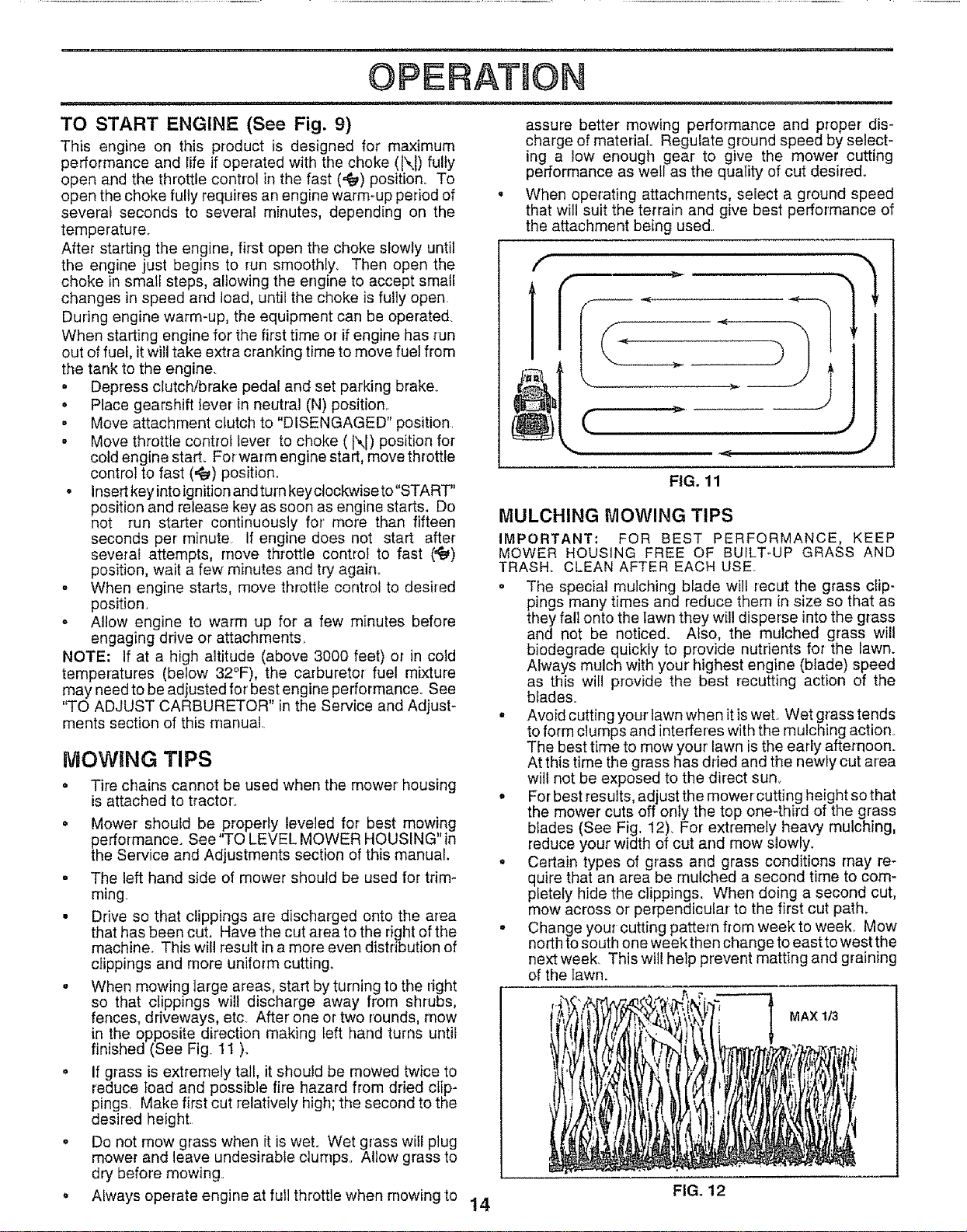
• When mowing large areas, start by turning to the right
so that clippings will discharge away from shrubs,
fences, driveways, etc After one or two rounds, mow
in the opposite direction making left hand turns ur_til
finished (See Fig 11 )_
• If grass is extremely tall, it should be mowed twice to
reduce toad and possible fire hazard from dried clip-
pings. Make first cut relatively high; the second to the
desired height
. Do not mow grass when it is wet. Wet grass will plug
mower and leave undesirable clumps. Allow grass to
dry before mowing°
o Always operate engine at full throttle when mowing to
assure better mowing performance and proper dis-
charge of material. Regulate ground speed by select-
ing a low enough gear to give the mower cutting
performance as well as the quality of cut desired_
When operating attachments, select a ground speed
that wil! suit the terrain and give best performance of
the attachment being used
FIG. 11
MULCHING MOWING TIPS
IMPORTANT; FOR BEST PERFORMANCE, KEEP
MOWER HOUSING FREE OF BUILT-UP GRASS AND
TRASH. CLEAN AFTER EACH USE..
o The special mulching blade will recut the grass ctip-
pings many times and reduce them in size so that as
they fall onto the lawn they will disperse into the grass
and not be noticed. Also, the mulched grass will
biodegrade quickly to provide nutrients for the Iawn.
Always mulch with your highest engine (blade) speed
as this witl provide the best recutting action of the
blades.
° Avoid cutting yourtawn when it iswet Wet grass tends
to form clumps and interferes with the mulching action
The best time to mow your lawn is the early afternoon.
At this time the grass has dried and the newly cut area
will not be exposed to the direct sun..
• Forbest results, adjust the mower cutting height so that
the mower cuts oft only the top one-third of the grass
blades (See Fig. 12)_ For extremely heavy mulching,
reduce your width of cut and mow slowly.
o Certain types of grass and grass conditions may re-
quire that an area be mulched a second time to com-
pletely hide the clippings. When doing a second cut,
mew across or perpendicular to the first cut path.
. Change your cutting pattern from week to week.. Mow
north to south one week then change to east to west the
next week_ This will help prevent matting and graining
of the lawn.
MAX 1/3
FIG. 12
14
CUSTOMER ESPONS BULmES
FILL IN DATES _'£y.O_" g
AS YOU COMPLETE _ _.____# _.,_'_
REGULAR SERVICE /'_T"/£X_/_'/_ '_/_>"£,_4._"_4_ySERVICE DATES
Check Brake Operation 1_
Check Tire Pressure _
T Check {or Loose Fasteners _ _'z ................6_ .......
R "'sharpen/Replace Mower Blades _ _ ! 6/4 ............
.....L b,ioationChart V' .........................V'
T Check Battery Level/Recharge _
0 Clean Battery and Terminals _ 6/'
R Check Transaxle Cooling I6/
Adjust Blade Belt(s) Tension ! . Ks
Adjust Motion Drive Belt(s) Tension 6_5
Check Engine Oil Level
Change Engine Oil ..
Clean Air Filter
E
N Clean Air Screen
G Inspect Muffler/Spark Arreeter
I Replace Oil Filter (If equipped)
N Clean Engine Cooling Fins I I
Replace Spark Plug
................................................ [i ]
Replace Air Filter Paper Cartridge
w--
v'
IV'2
Iv'2
V'
e'%
Replace Fuel Filter
1 - Change mere ellen when operating under a heavy load or in high ambient lemperalu_'es
2 - Service moreellen whenoperatingin dirtyor dustyconditions
3 - If equippedwithoil filler, changeoil every50heels
4 - Replace blades moreellen when mowing in sandy soil
V'2
5 _ II equipped wilh adjustable system
6 - Nol required if equipped wilh maintenance4ree battery
7 - Tighten front a×te pivot boll Io 35 Itqbs maximum
Do not ovedighten
GENERAL RECOMMENDATIONS
The warranty on this tractor does not cover items that have
been subjected to operator abuse or negligence To
receive full value from the warranty, operator must maintain
tractor as instructed in this manual
Some adjustments will need to be made periodically to
properly maintain your tractor
All adjustments in the Service and Adjustments section of
this manual should be checked at least once each season
Once a year you should replace the spark plug, clean
or replace air filter, and check blades and belts for
wear, A new spark plug and clean air filter assure
proper air-fuel mixture and help your engine run better
and last longer
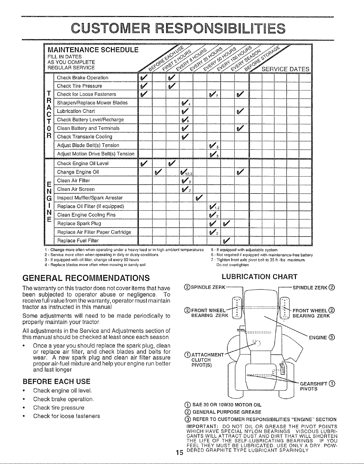
LUBRICATION CHART
(_)SPINDLE ZERK_-'_/....___.__ _[_ SPINDLE ZERK (_)
NE®
(_ ATTACHMENT"
CLUTCH
PIVOT(S)
BEFORE EACH USE
,, Check engine oil level
- Check brake operation,
. Check tire pressure
• Check for loose fasteners
O
PIVOTS
(_) SAE 30 OR 10W30 MOTOR OIL
(_ GENERAL PURPOSE GREASE
(_ REFER TO CUSTOMER RESPONStBILtTtES "ENGINE" SECTION
IMPORTANT: DO NOT OIL OR GREASE THE PIVOT POINTS
WHICH HAVE SPECIAL NYLON BEARINGS VISCOUS LUBRI-
CANTS WILL ATTRACT DUST AND DIRT THAT WILL SHORTEN
THE LIFE OF THE SELF-LUBRICATING BEARINGS 1F YOU
FEEL THEY MUST BE LUBRICATED. USE ONLY A DRY. POW-
15 DERED GRAPHITE TYPE LUBRICANT SPARINGLY
R ....
CUSTOMER RESPONSiBILITiES
TRACTOR TO SHARPEN BLADE (See Fig. 14)
Aiways observe safety rules when performing any mainte- Care should be taken to keep the blade balanced_ An
nance, unbalanced blade will cause excessive vibration and even-
tual damage to mower and engine
BRAKE OPERATION
If tractor requires more than six (6) feet stopping distance
at high speed in highest gear, then brake must be adjusted
(See "TO ADJUST BRAKE" in the Service and Adjust-
ments section of this manuat).
TIRES
• Maintain proper air pressure in al! tires (See "PROD-
UCT SPECIFICATIONS" on page 3 of this manual).
• Keep tires free of gasoline, oil, or insect control chemi-
o The blade can be sharpened with a file or on a grinding
wheel, Do not attempt to sharpen while on the mower°
° To check blade balance, you will need a 5/8" diameter
steel bolt, pin, ora cone balancer. (When using a cone
balancer, follow the instructions supplied with bal_
ancer)
° Slide blade on toan unthleaded portion of the steel bolt
or pin and hofd the boit or pin paralfel with the ground.
If blade is balanced, it should remain in a horizontal
position, If either end of the blade moves downward,
sharpen the heavy end until the blade [s balanced,
NOTE: Do not use a nail for balancing blade. The lobes of
the center hole may appear to be cente{ed, but are not,
cals which can harm rubber.
Avoid stumps, stones, deep ruts, sharp objects and
other hazards that may cause tire damage.
BLADE CARE
For' best results mower blades must be kept sharp, Re-
place bent or damaged blades
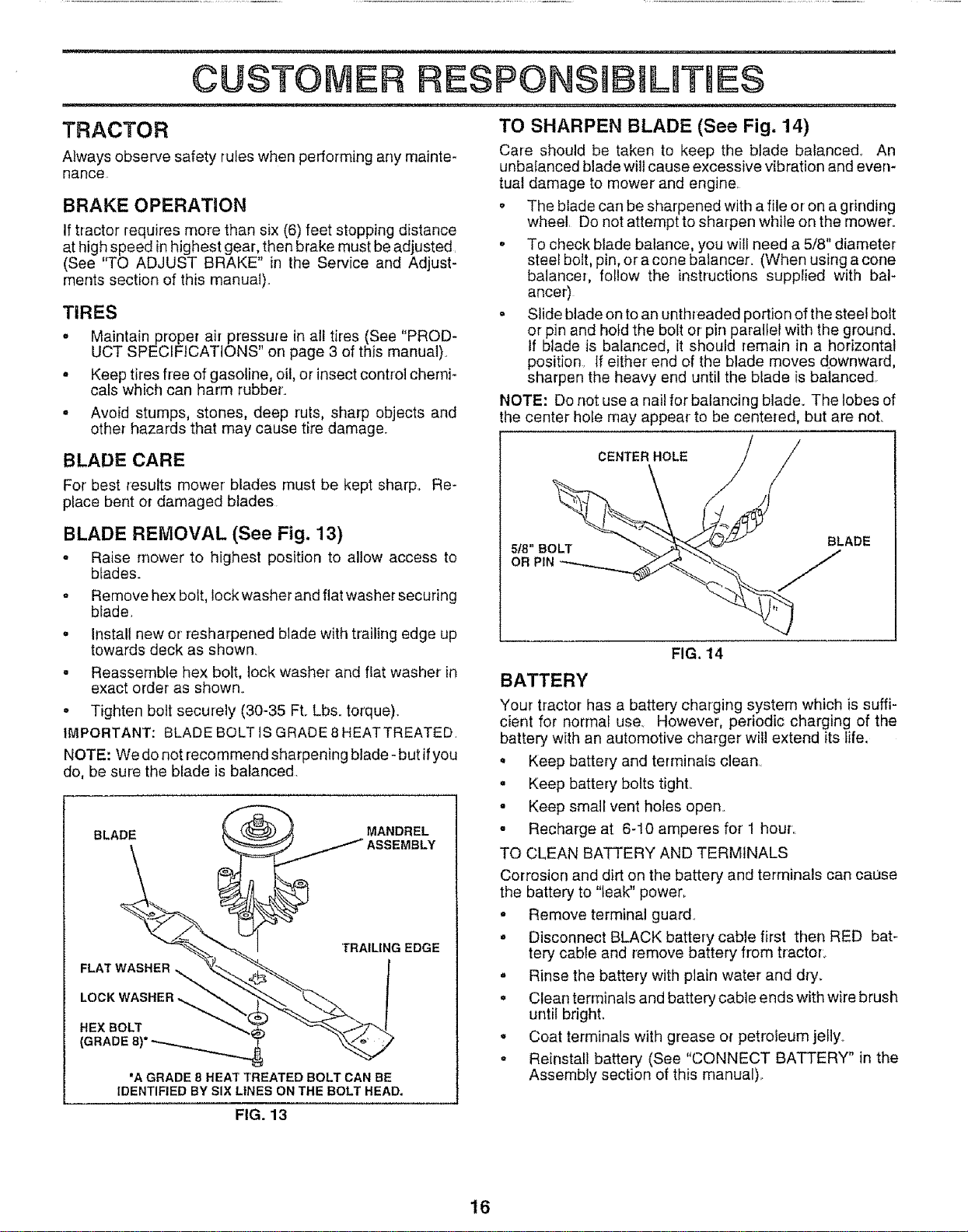
BLADE REMOVAL (See Fig, 13)
* Raise mower to highest position to allow access to
btades.
* Remove hex bolt, lock washer and flat washer securing
blade,
° Install new or resharpened blade with trailing edge up
towards deck as shown.
. Reassemble hex bolt, lock washer and flat washer in
exact order as shown.
o Tighten bolt securely (30-35 Ft. Lbs. torque).
IMPORTANT: BLADE BOLT IS GRADE 8 HEATTREATED.
NOTE: We do not recommend sharpening blade- but ifyou
do, be sure the blade is balanced,
BLADE _--_ MANDREL
(GRADE 8)"_ "_
IDENTIFIED BY SIX LINES ON THE BOLT HEAD.
CENTER HOLE
518" BOLT BLADE
OR PiN
FIG. 14
BATTERY
Your tractor has a battery charging system which is suffi-
cient for normal use_ However, periodic charging of the
battery with an automotive charger will extend its life,
• Keep battery and terminals clean,
• Keep battery bolts tight,.
• Keep small vent holes open,
° Recharge at 6-10 amperes for 1 hour,.
TO CLEAN BATTERY AND TERMINALS
Corrosion and dirt on the battery and terminals can caase
the battery to "leak" power_
- Remove terminal guard.
° Disconnect BLACK battery cable first then RED bat-
tery cable and remove battery from tractor,,
° Rinse the battery with plain water and dry.
. Clean terminals and battery cable ends with wire brush
until bright.
o Coat terminals with grease o_ petroleum jelly.,
• Reinstall battery (See "CONNECT BATTERY" in the
Assembly section of this manual),.
FIG. 13
16
CUSTOM5
: i, in
ESPONS BtL ES
V-BELTS
Check V-belts for deterioration and wear after 100 hours of
operation and replace if necessary. The belts are not
adjustable, Replace belts ifthey begin to slip from wear,
TRANSAXLE COOLING
Keep transaxfe free from build-up of dirt and chaff which
can restrict cooling
ENGINE
LUBRICATION
Only use high quality detergent oil rated with API service
classification SForSG. Select the oil's SAE viscosity grade
according to your expected operating temperature.,
SAE VISCOSITY GRADES
°F -20° 0° 3o_ 32° 40_ 60° 80_ 1o0"
TEMPERATURE RANGE ANTICIPATED BEFORE NEXT O_L CHANGE
FIG, 15
NOTE: Although multi-viscosity oils (5W30. t 0W30 etc,,)
improve starting in cold weather, these multi-viscosity oils
will result in increased oil consumption when used above
32°F. Check your engine oil level more frequently to avoid
possible engine damage from running low on oil
Change the oil after the first two hours of operation and
every 50 hours thereafter or at least once a year if the
tractor is not used for 50 hours in one year,
Check the crankcase oil level before starting the engine
and after each eight (8) hours of operation. Tighten oil fill
cap/dipstick securely each time you check the oil level,,
TO CHANGE ENGINE OIL (See Figs 15 and 16)
Determine temperature range expected before oil change,
All oil must meet API service classification SF or SG
o Be sure tractor is on level surface,
• Oil will drain more freely when warm
• Catch oil in a suitable container
o Remove oil fil! cap/dipstick Be careful not to allow dirt
to enter the engine when changing oil,
• Remove drain plug,
° After oil has drained completely, replace oil drain plug
and tighten securely.,
° Refill engine with oil through oil fill dipstick tube. Pour
slowly, Do not overfill, For approximate capacity see
"PRODUCT SPECIFICATIONS" on page 3 of this
manual,
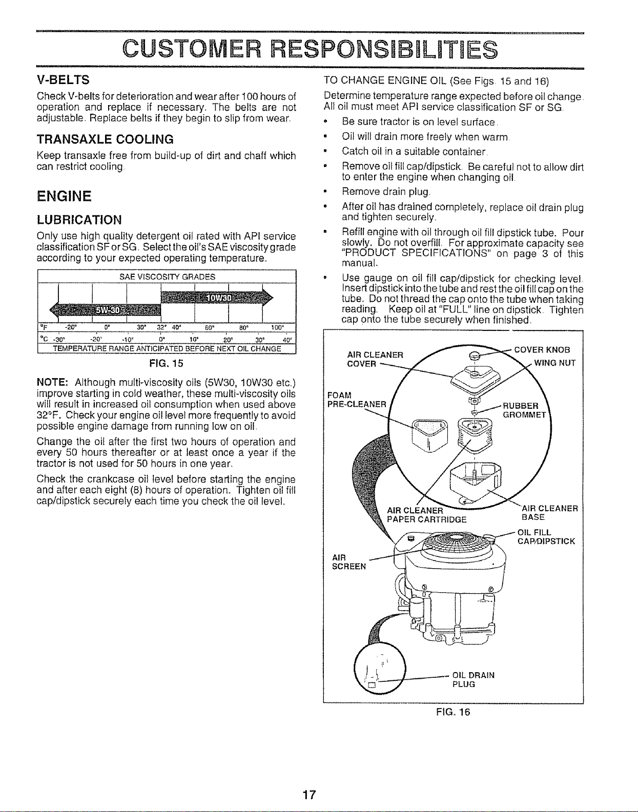
Use gauge on oil fill cap!dipstick for checking level
fnsert dipstick into the tube and rest the oil fill cap on the
tube, Do not thread the cap onto the tube when taking
reading, Keep oil at "FULL" line on dipstick Tighten
cap onto the tube securely when finished,
AIR CLEANER KNOB
COVER WING NUT
FOAM
PRE-CLEANER
AIR
SCREEN
PAPER CARTRIDGE
BASE
OIL FILL
CAP/DIPSTICK
OIL DRAIN
PLUG
FIG, 16
17
i i,i ii, i,illl i,i , iii
CUSTOMER RESPONSHBmLITIES
ill nilili,, in,l,n nil n nul I
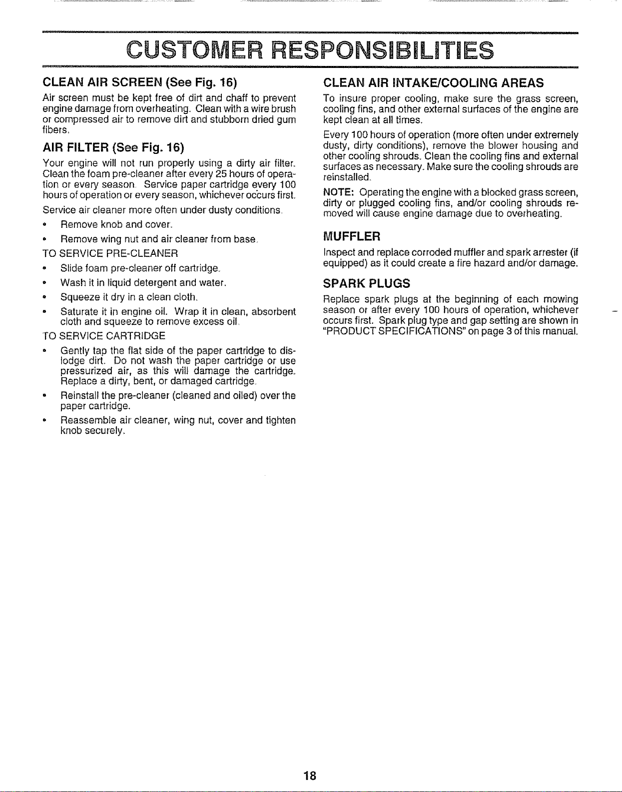
CLEAN AIR SCREEN (See Fig. 16) CLEAN AIR INTAKE/COOLING AREAS
Air screen must be kept free of dirt and chaff to prevent
engine damage from overheating, Clean with a wire brush
or compressed air to remove dirt and stubborn dried gum
fibers_
AIR FILTER (See Fig. 16)
Your engine will not run properly using a dirty air filter_
Clean the foam pre-oleaner after every 25 hours of opera-
tion or every season. Service paper cartridge every t00
hours of operation or every season, whichever occurs first.
Service air cleaner' more often under dusty conditions
= Remove knob and cover..
= Remove wing nut and air cleaner from base.
TO SERVICE PRE-CLEANER
o Slide foam pre-cleaner off cartridge.
o Wash it in liquid detergent and water.
o Squeeze it dry in a cfean cloth.
° Saturate it in engine oil. Wrap it in clean, absorbent
cloth and squeeze to remove excess oil.
TO SERVICE CARTRIDGE
° Gently tap the flat side of the paper cartridge to dis-
lodge dirt_ Do not wash the paper cartridge or use
pressurized air, as this wilt damage the cartridge..
Replace a dirty, bent, or damaged cartridge
• Reinstall the pre-cleaner (cleaned and oiled) over the
paper cartridge.
° ReassembLe air cleaner, wing nut, cover and tighten
knob securely._
To insure proper cooling, make sure the grass screen,
cooling fins, and other external surfaces of the engine are
kept clean at all times.
Every 100 hours of operation (more often under extremely
dusty, dirty conditions), remove the blower housing and
other cooling shrouds. Clean the cooling fins and external
surfaces as necessary. Make sure the cooling shrouds are
reinstalle&
NOTE: Operating the engine with a blocked grass screen,
dirty or' plugged cooling fins, and/or cooling shrouds re-
moved will cause engine damage due to overheating.
MUFFLER
Inspect and replace corroded muffler and spark arrester (if
equipped) as it could create a fire hazard and/or damage.
SPARK PLUGS
Replace spark plugs at the beginning of each mowing
season or after every 100 hours of operation, whichever
occurs first. Spark plug type and gap setting are shown in
"PRODUCT SPECIFICATIONS" on page 3 of this manual°
18
i u
CUSTOME
ESPONS B LmTtES
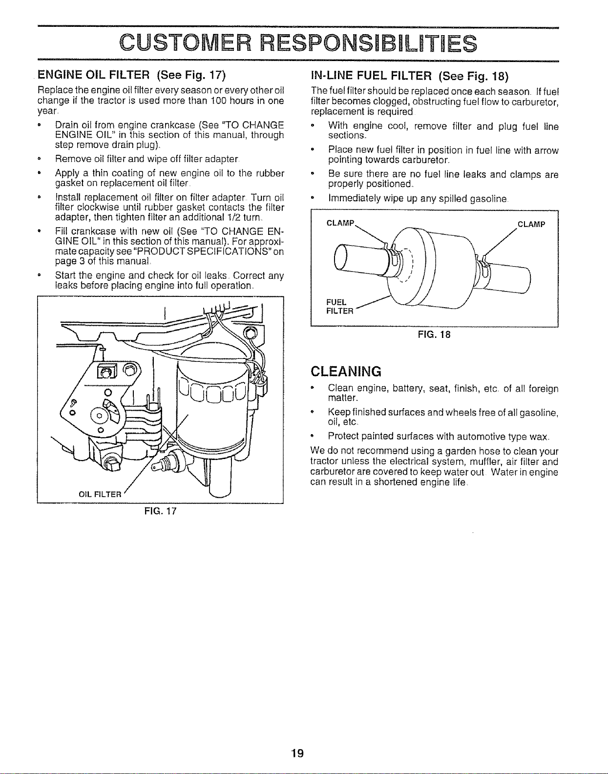
ENGINE OIL FILTER (See Fig. 17)
Repface the engine oil filter every season or every other oil
change if the tractor is used more than 100 hours in one
year.
• Drain oil from engine crankcase (See "TO CHANGE
ENGINE OIL" in this section of this manual, through
step remove drain plug)
• Remove oil filter and wipe off filter adapter
• Appfy a thin coating of new engine oil to the rubber
gasket on replacement oil filter
o Install replacement oil filter on filter adapter Turn oil
filter clockwise until rubber gasket contacts the filter
adapter, then tighten filter an additional !/2 turn.
, Fill crankcase with new oil (See "TO CHANGE EN-
GINE OIL" in this section of this manual). For approxi-
mate capacity see "PRODUCT SPECIFICATIONS" on
page 3 of this manual
• Start the engine and check for oil leaks Correct any
leaks before placing engine into full operation.
t
OIL FILTER
IN-LINE FUEL FILTER (See Fig. 18)
The fuel filter should be replaced once each season If fuel
filter becomes clogged, obstructing fuel flow to carburetor,
replacement is required
• With engine cool, remove filter and plug fuel line
sections_
• Place new fuel filter in position in fuel line with arrow
pointing towards carburetor.
. Be sure there are no fuel line leaks and clamps are
properly positioned
• Immediately wipe up any spilled gasoline
CLAMP
FUEL
FILTER
FIG. 18
CLEANING
• Clean engine, battery, seat, finish, etc, of all foreign
matter.
. Keep finished surfaces and wheels free of all gasoline,
oi!, etc.
. Protect painted surfaces with automotive type wax_
We do not recommend using a garden hose to clean your
tractor unless the electrical system, muffler, air filter and
carburetor are covered to keep water out Water in engine
can result in a shortened engine fife
FIG. 17
19
CAUTION: BEFORE PERFORMING ANY SERVICE OR ADJUSTMENTS:
o
o
o
o
o
Depress clutch/brake pedal fully and set parking brake=
Place gearshift lever in neutral (N) position.
Place attachment clutch in "DISENGAGED" position.
Turn ignition key "OFF" and remove key°
Make sure the blades and all moving parts have completely stopped,
Disconnect spark plug wire from spark plug and place wire where it cannot come in contact with
plug.
TRACTOR
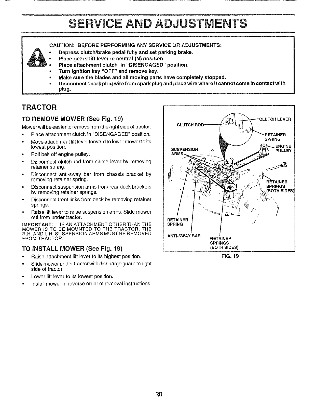
TO REMOVE MOWER (See Fig. 19)
Mower willbe easier to remove from the right side of tractor..
• Place attachment clutch in "DISENGAGED" position.
, Move attachment lift lever forward to lower mower to its
lowest position.
o Roll belt off engine pulley.
• Disconnect clutch rod from clutch lever by removing
retainer spring_
° Disconnect anti-sway bar from chassis bracket by
removing retainer spring.
o Disconnect suspension arms from rear deck brackets
by removing retainer springs.
• Disconnect front links from deck by removing retainer
springs..
• Raise lift lever to raise suspension arms. Slide mower
out from under tractor'.
IMPORTANT: IF AN ATTACHMENT OTHER THAN THE
MOWER iS TO BE MOUNTED TO THE TRACTOR. THE
R.H. AND L.H. SUSPENSION ARMS MUST BE REMOVED
FROM TRACTOR..
TO INSTALL MOWER (See Fig. 19)
• Raise attachment lift lever to its highest position_
° Slide mower under tractorwith discharge guard to right
side of tractor.
° Lower lift lever to its lowest position.
, Instali mower in reverse order of removal instructions.
CLUTCH R4
SUSPENSION
RETAINER
SPRING J"
ANTI-SWAY BAR
RETAINER
SPRINGS
(BOTH SIDES)
FIG. 19
LEVER
SPRING
PULLEY
RETAINER
SPRINGS
SIDES
2O
SERVICE AND ADJUSTMENTS
J
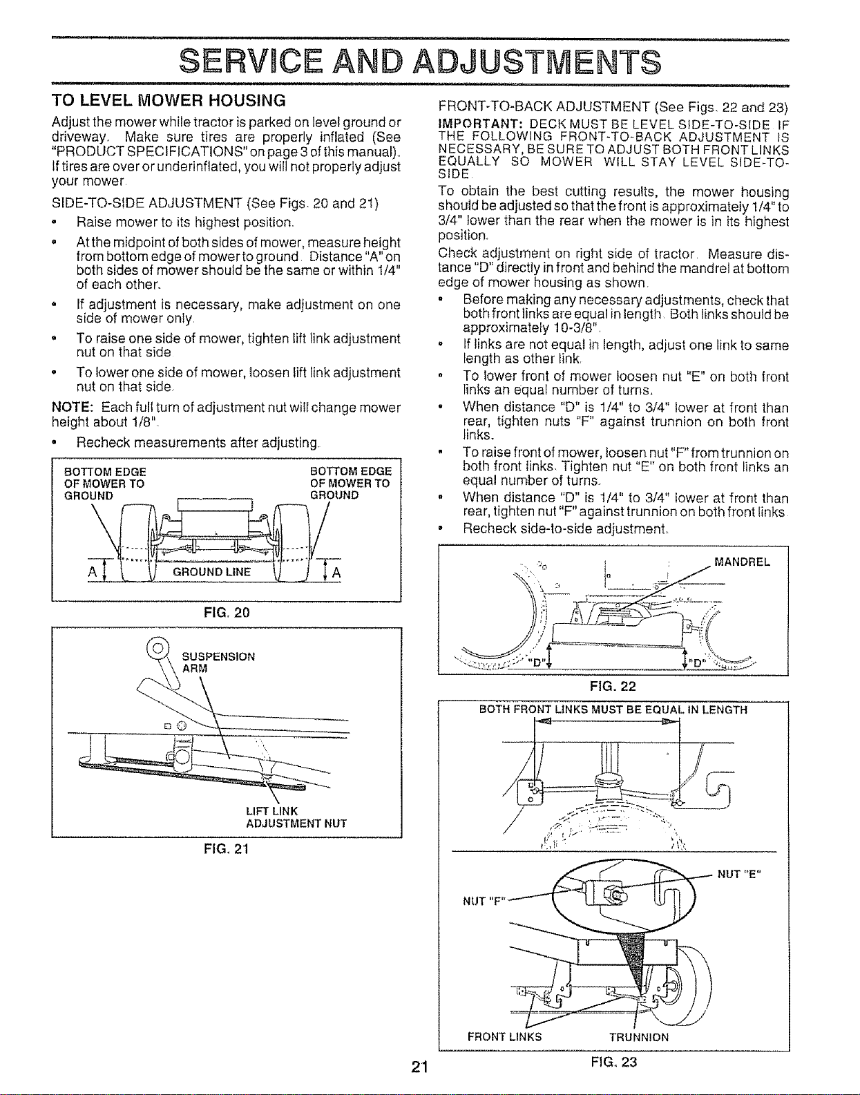
TO LEVEL MOWER HOUSING FRONT-TO-BACK ADJUSTMENT (See Figs, 22 and 23)
Adjust the mower while tractor is parked on level ground or
driveway_ Make sure tires are properly inflated (See
"PRODUCT SPECIFICATIONS" on page 3 of this manuat)..
Iftires are over or underinflated, you will not properly adjust
your mower
SIDE-TO-SIDE ADJUSTMENT (See Figs. 20 and 21)
. Raise mower to its highest position..
. At the midpoint of both sides of mower, measure height
from bottom edge of mowerto ground Distance"A" on
both sides of mower should be the same or within 1/4"
of each other..
a
o
If adjustment is necessary, make adjustment on one
side of mower only.
To raise one side of mower, tighten lift link adjustment
nut on that side
• To lower one side of mower, loosen lift link adjustment
nut on that side
NOTE: Each full turn of adjustment nut will change mower
height about 1/8"
• Recheck measurements after adjusting.
BOTTOM EDGE BOTTOM EDGE
OF MOWER TO OF MOWER TO
GROUND GROUND
IMPORTANT: DECK MUST BE LEVEL SIDE-TO-SIDE IF
THE FOLLOWING FRONT-TO-BACK ADJUSTMENT lS
NECESSARY, BE SURE TO ADJUST BOTH FRONT LINKS
EQUALLY SO MOWER WILL STAY LEVEL SIDE-TO-
SIDE
TO obtain the best cutting results, the mower housing
should be adiusted so that the front isapproximately 1/4" to
3/4" lower than the rear when the mower is in its highest
position.
Check adjustment on right side of tractor Measure dis-
tance "D" directly infront and behind the mandrel at bottom
edge of mower housing as shown.
° Before making any necessary adjustments, check that
both front links are equal in length. Both links should be
approximately 10-3/8".
• If links are not equal in length, adjust one link to same
length as other link.
° To lower front of mower loosen nut "E" on both front
links an equal number of turns.
° When distance "D" is 1/4" to 3/4" lower at front than
rear, tighten nuts "F" against trunnion on both front
links.
. To raise front of mower, toosen nut"F" from trunnion on
both front links. Tighten nut "E" on both front links an
equal number of turn&
° When distance "D" is 1/4" to 3/4" lower at front than
rear, tighten nut "F" against trunnion on both front links
• Recheck side-to-side adjustment.
GROUND LINE
FIG. 20
SUSPENSION
ARM
LIFT LINK
ADJUSTMENT NUT
FIG, 21
FIG. 22
BOTH FRONT LINKS MUST BE EQUAL IN LENGTH
/
NUT "F"
FRONT LINKS TRUNN!ON
NUT "E"
21 FIG. 23
SERVICE AND ADJUSTMENTS
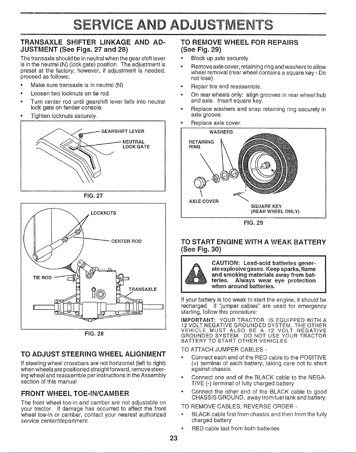
WITH PARKING BRAKE "ENGAGED"
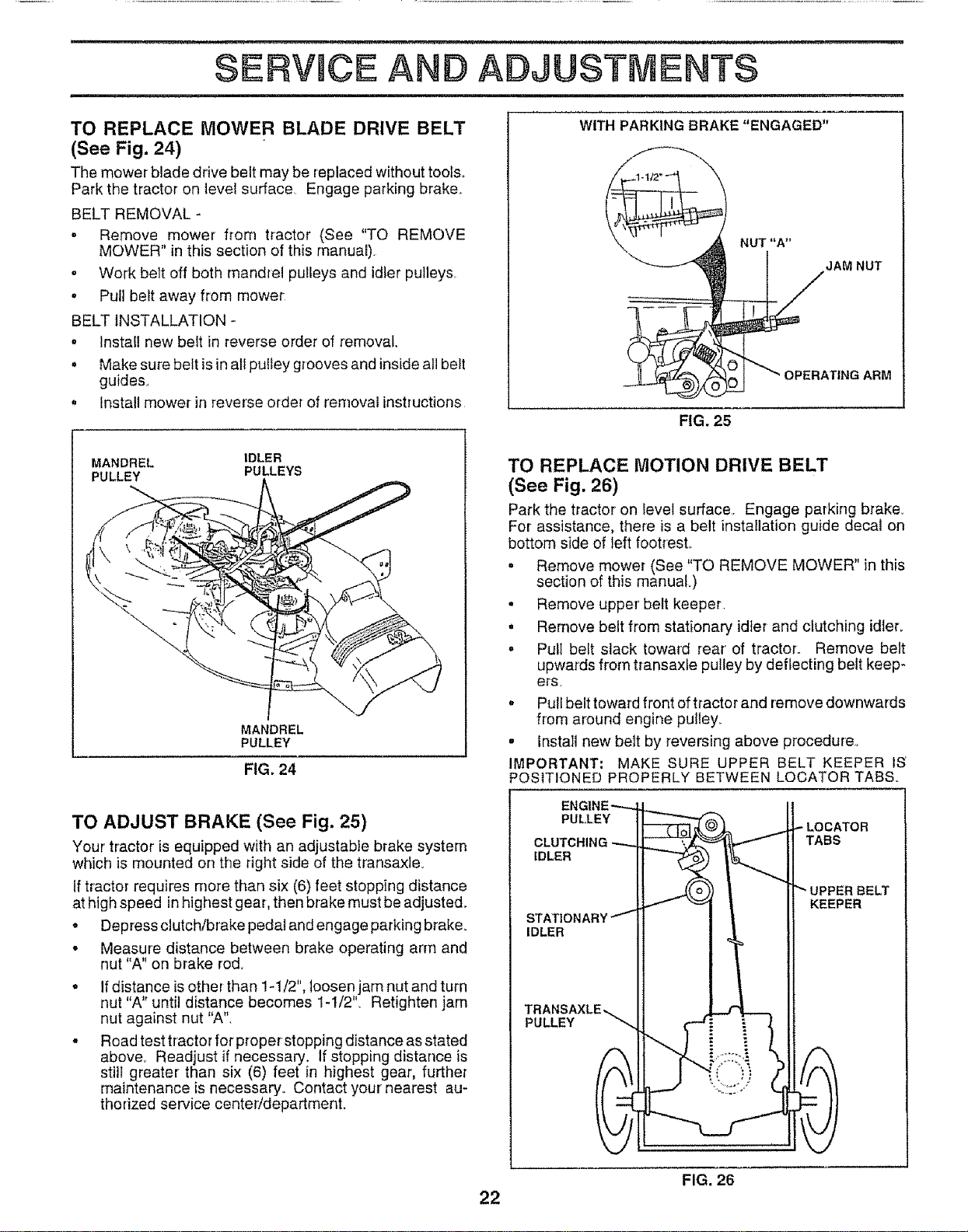
TO REPLACE MOWER BLADE DRIVE BELT
(See Fig. 24)
The mower blade drive belt may be replaced without tools°
Park the tractor on level surface, Engage parking brake,.
BELT REMOVAL -
• Remove mower from tractor (See "TO REMOVE
MOWER" in this section of this manual).
. Work belt off both mandrel pulleys and idler pulleys,
, Pull belt away from mower
BELT iNSTALLATION -
o Install new belt in reverse order of removal.
• Make sure belt isin all pulley grooves and inside all belt
guides,
• Install mower in reverse order of removal instructions
FIG. 25
MANDREL IDLER
PULLEY PULLEYS
MANDREL
PULLEY
FIG. 24
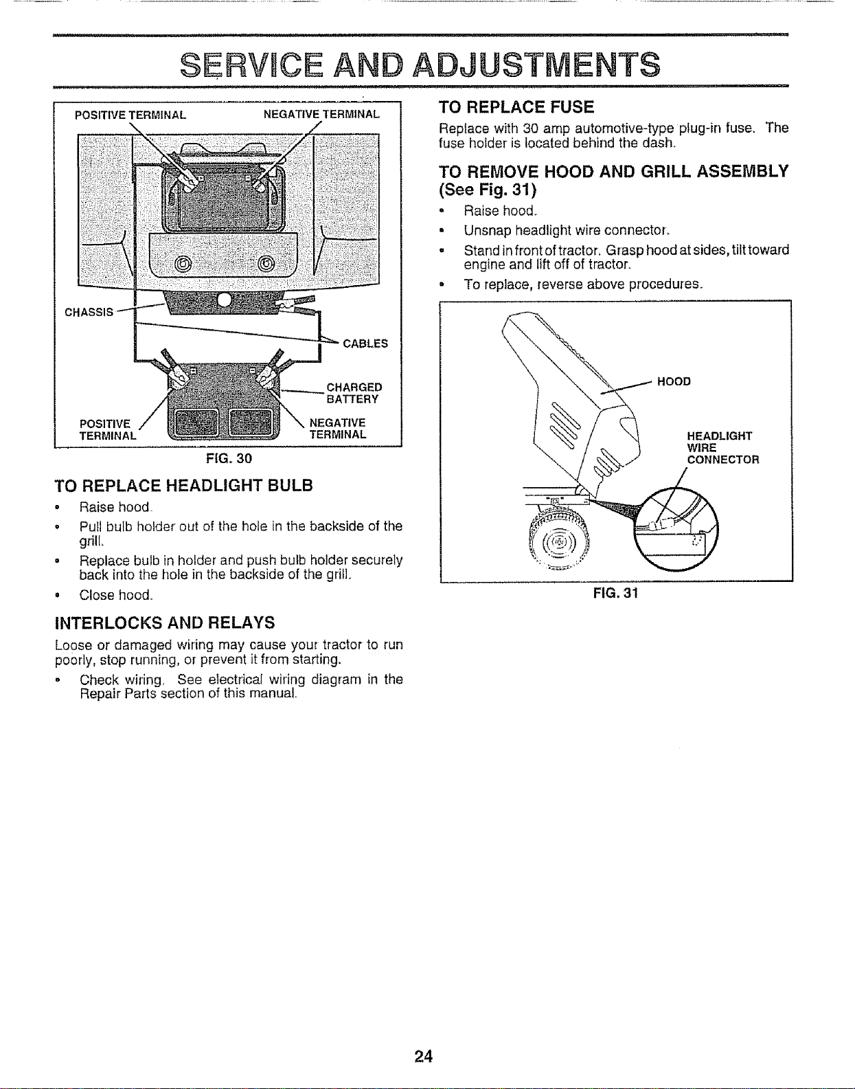
TO REPLACE MOTION DRIVE BELT
(See Fig. 26)
Park the tractor on level surface, Engage parking brake_
For assistance, there is a belt installation guide decal on
bottom side of left footresL
= Remove mower (See "TO REMOVE MOWER" in this
section of this manuaL)
, Remove upper' belt keeper
, Remove belt from stationary idler and clutching idler.
. Pull belt slack toward rear" of tractor,, Remove belt
upwards from transaxle pulley by deflecting belt keep-
et_s.
° Puli belt toward front of tractor and remove downwards
from around engine pulley_
. Install new belt by reversing above procedure,,
IMPORTANT: MAKE SURE UPPER BELT KEEPER IS'
POSITIONED PROPERLY BETWEEN LOCATOR TABS.
TO ADJUST BRAKE (See Fig. 25)
Your tractor is equipped with an adjustable brake system
which is mounted on the right side of the transaxle_
If tractor requires more than six (6) feet stopping distance
at high speed in highest gear, then brake must be adjusted_
- Depress clutch/brake pedal and engage parking brake_
• Measure distance between brake operating arm and
nut "A" on brake rod.
. If distance isother than 1-1/2", loosen jam nut and turn
nut "A" until distance becomes 1-1/2'L Retighten jam
nut against nut "A",
° Road test tractor for proper stopping distance as stated
above,1 Readjust if necessary. If stopping distance is
still greater than six (6) feet in highest gear, further
maintenance is necessary° Contact your nearest au-
thorized service center/department.
PULLEY
IDLER
IDLER
PULLEY
BELT
KEEPER
22
FIG. 26
SERVICE AND ADJUSTMENTS
TRANSAXLE SHIFTER LINKAGE AND AD-
JUSTMENT (See Figs. 27 and 28)
The transaxle shoutd be in neutral when the gear shift lever
is in the neutral (N) (lock gate) position_ The adjustment is
preset at the factory; however, if adjustment is needed,
proceed as follows:
. Make sure transaxle is in neutral (N)
• Loosen two locknuts on tie rod,
° Turn center rod until gearshift lever falls into neutral
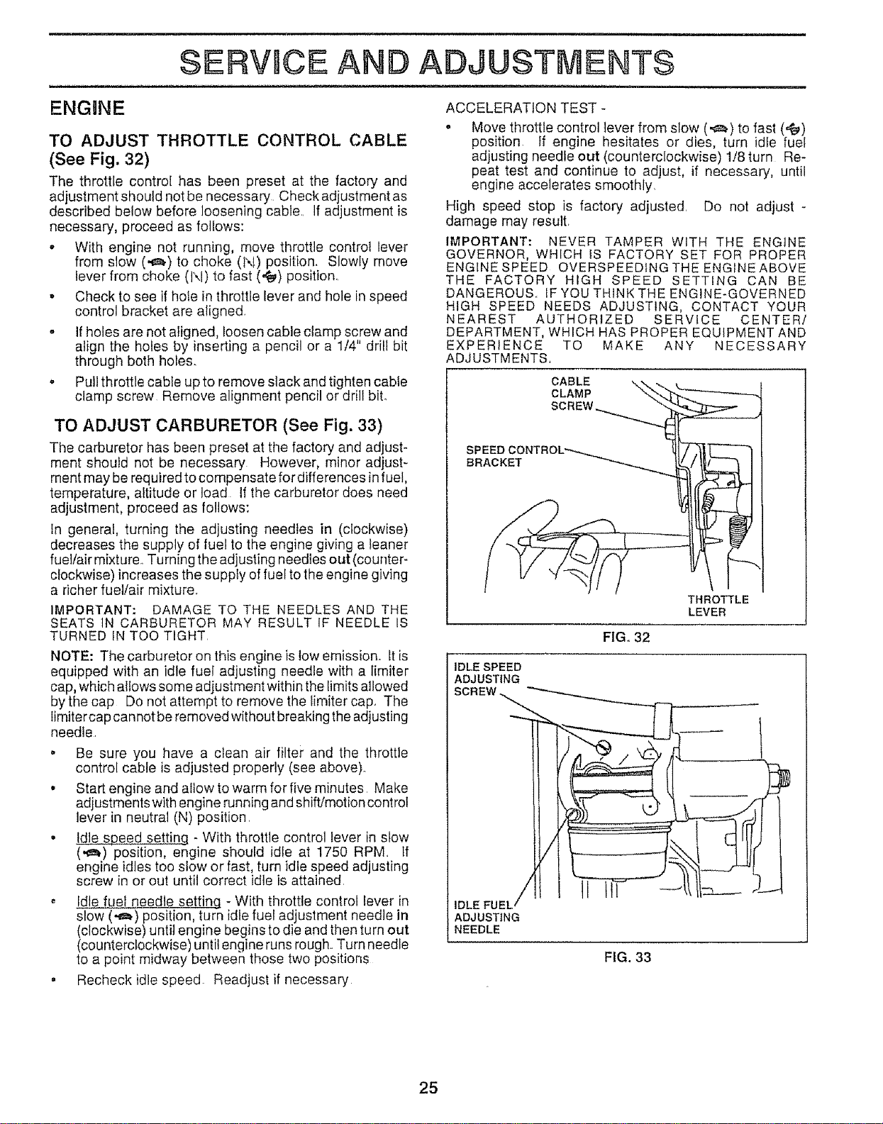
TO REMOVE WHEEL FOR REPAIRS
(See Fig. 29)
o Block up axle securely
o Remove axle cover, retaining ring and washers to allow
wheel removal (rear wheel contains a square key - Do
not lose).
o Repair tire and reassemble.,
° On rear wheels only: align grooves in rear wheel hub
and axle. Insert square key
lock gate on fender console,
Tighten locknuts securely,
o Replace washers and snap retaining ring securely in
axle groove
° Replace axle cover.,
WASHERS
RETAINING
RiNG
AXLECOVER
SQUARE KEY
(REAR WHEEL ONLY)
FIG. 29
TO START ENGINE WITH A WEAK BATTERY
See Fig. 30)
&
CAUTION: Lead-acid batteries gener-
ateexplosivegases. Keep sparks,flame
and smoking materials away from bat-
teries. Always wear eye protection
when around batteries.
TRANSAXLE
FIGo 28
TO ADJUST STEERING WHEEL ALIGNMENT
If steering wheel crossbars are not horizontal (left to right)
when wheels are positioned straight forward, remove steer-
ing wheel and reassemble per instructions in the Assembly
section of this manual,
FRONT WHEEL TOE-IN/CAMBER
The front wheel toe-in and camber are not adjustable on
your tractor, tf damage has occurred to affect the front
wheel toe-in or camber, contact your nearest authorized
service center/department.
If your battery is too weak to start the engine, it should be
recharged If "jumper cables" are used for emergency
starting, follow this procedure:
IMPORTANT: YQURTRACTOR IS EQUIPPED WITH A
12 VOLT NEGATIVE GROUNDED SYSTEM. THE OTHER
VEHICLE MUST ALSO BE A 12 VOLT NEGATIVE
GROUNDED SYSTEM. DQ NOT USE YOUR TRACTOR
BATTERY TO START OTHER VEHICLES
TO ATTACH JUMPER CABLES -
° Connect each end of the RED cable to the POSITIVE
(+) terminal of each battery, taking care not to short
against chassis,
° Connect one end of the BLACK cable to the NEGA-
TIVE (-) terminal of fully charged battery
° Connect the other end of the BLACK cable to good
CHASSIS GROUND, away from fuel tank and battery,
TO REMOVE CABLES, REVERSE ORDER -
• BLACK cable first from chassis and then from the fully
charged battery
o RED cable last from both batteries
23
=, =,=,, i
SERVWCE AND ADJUSTMENTS
POSITIVE TERMINAL
NEGATIVE TERMINAL
CABLES
CHARGED
BATTERY
POSITIVE NEGATIVE
TERMINAL TERMINAL
FIGo30
TO REPLACE HEADLIGHT BULB
. Raise hood
• Put1bulb holder out of the hole in the backside of the
grill
= Replace bulb in holder and push bulb holder securely
back into the hole in the backside of the grill
° Close hood.
INTERLOCKS AND RELAYS
Loose or damaged wiring may cause your tractor to run
poorly, stop running, or prevent it from starting.
• Check wiring See electrical wiring diagram in the
Repair Parts section of this manual.
TO REPLACE FUSE
Replace with 30 amp automotive-type plug-in fuse, The
fuse holder is located behind the dash°
TO REMOVE HOOD AND GRILL ASSEMBLY
(See Fig. 31)
• Raise hood_
. Unsnap headlight wire connectoL
= Stand in front of tractor. Grasp hood at sides, titttoward
engine and lift off of tractor,
• To replace, reverse above procedures_
HOOD
HEADLIGHT
WIRE
CONNECTOR
FIG, 31
24
SERWCE AND ADJUSTMENTS
ENGgNE
TO ADJUST THROTTLE CONTROL CABLE
(See Fig, 32)
The throttle controi has been preset at the factory and
adjustmentshould notbe necessary Checkadjustmentas
described below before loosening cable.. If adjustment is
necessary, proceed as follows:
o With engine not running, move throttle control lever
from slow (,_,) to choke (N) position. Slowly move
lever from choke (l\l) to fast (=f_) position.
o Check to see if hote in throttle lever and hole in speed
control bracket are aligned.
• if holes are not aligned, loosen cable clamp screw and
align the holes by inserting a pencil or a 1/4" drill bit
through both holes.
o Pull throttle cable up to remove slack and tighten cable
clamp screw Remove alignment pencil or drNtbiL
TO ADJUST CARBURETOR (See Fig. 33)
The carburetor has been preset at the factory and adjust-
ment shouid not be necessary However, minor ad}ust-
ment may be required to compensate fordifferences in fuel,
temperature, altitude or load If the carburetor does need
adjustment, proceed as follows:
in generai, turning the adjusting needles in (clockwise)
decreases the supply of fuel to the engine giving a leaner
fuel/air mixture° Turning the adjusting needtes out (counter-
clockwise) increases the supply of fuel to the engine giving
a richer fuel!air mixture.
IMPORTANT: DAMAGE TO THE NEEDLES AND THE
SEATS ]N CARBURETOR MAY RESULT IF NEEDLE IS
TURNED IN TOO TIGHT
NOTE: The carburetor on this engine is low emission_ it is
equipped with an idle fuel adjusting needle with a limiter
cap, which allows some adjustment within the limits allowed
bythe cap Do not attempt to remove the iimiter cap, The
Iimitercap can notbe removed without breaking the adjusting
needle.
o Be sure you have a ctean air filter" and the throttle
control cable is adjusted properly (see above),,
• Start engine and allow to warm for five minutes Make
adjustments with engine running and shift/motion control
lever in neutral (N) position,
• Idle speed setting - With throttle control tever in stow
(,,_,) position, engine should idle at 1750 RPM, If
engine idles too slow or fast, turn idle speed adjusting
screw in or out until correct idle is attained,
Idle fuel needle setting - With throttle control lever in
slow (._) position, turn idle fuel adjustment needle in
(clockwise) until engine begins to die and then turn out
(counterclockwise) until engine runs rough. Turn needle
to a point midway between those two positions
• Recheck idle speed. Readjust if necessary
ACCELERATION TEST -
o Move throttle control lever from slow (,_) to fast (._,)
position. If engine hesitates or dies, turn idfe fuel
adjusting needfe out (counterclockwise) 1/8 turn Re-
peat test and cont}nue to adjust, if necessary, until
engine accelerates smoothly.
High speed stop is factory adjusted. Do not adjust -
damage may result.
IMPORTANT: NEVER TAMPER WITH THE ENGINE
GOVERNOR, WHICH tS FACTORY SET FOR PROPER
ENGINE SPEED OVERSPEEDtNG THE ENGINE ABOVE
THE FACTORY HIGH SPEED SETTING CAN BE
DANGEROUS.. IF YOU THINK THE ENGINE-GOVERNED
HIGH SPEED NEEDS ADJUSTING, CONTACT YOUR
NEAREST AUTHORIZED SERVICE CENTER/
DEPARTMENT, WHICH HAS PROPER EQUIPMENT AND
EXPERIENCE TO
ADJUSTMENTS,
CABLE
CLAMP
SPEED CONTROL_-_...,_
BRACKET
MAKE ANY NECESSARY
THROTTLE
LEVER
FIG. 32
IDLE SPEED
ADJUSTING
IDLE FUEL /
ADJUSTING
NEEDLE
FIG. 33
25
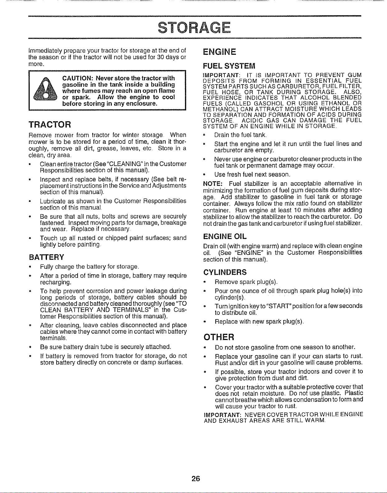
STORAGE
Immediately prepare your tractor for storage at the end of
the season or if the tractor will not be used for 30 days or
more.
&
CAUTION: Never store the tractor with
gasoline in tile tank inside a building
where fumes may reach an open flame
or spark. Allow the engine to cool
before storing in any enclosure.
TRACTOR
Remove mower from tractor for winter storage When
mower is to be stored for a period of time, clean it thor-
oughly, remove all dirt, grease, leaves, etc. Store in a
clean, dry area.
• Clean entire tractor (See"CLEANING" inthe Customer
Responsibilities section of this manual).
• inspect and replace belts, if necessary (See belt re-
placement instructionsin the Service and Adjustments
section of this manual).
• Lubricate as shown in the Customer Responsibilities
section of this manual_
• Be sure that all nuts, bolts and screws are securely
fastened Inspect moving parts for damage, breakage
and wear. Replace if necessary
. Touch up all rusted or chipped paint surfaces; sand
Iightly before painting.
BATTERY
• Fully charge the battery for storage.
• After a period of time in storage, battery may require
recharging.
. To help prevent corrosion and power leakage during
long periods of storage, battery cables should be
disconnected and battery cleaned thoroughly (see "TO
CLEAN BATTERY AND TERMINALS" in the Cus-
tomer Responsibilities section of this manual).
o After cleaning, leave cables disconnected and place
cables where they cannot come in contact with battery
terminals_
. Be sure battery drain tube is securely attached.
- If battery is removed from tractor for storage, do not
store battery directly on concrete or damp surfaces.
ENGINE
FUEL SYSTEM
IMPORTANT: IT JS iMPORTANT TO PREVENT GUM
DEPOSITS FROM FORMING IN ESSENTIAL FUEL
SYSTEM PARTS SUCH AS CARBURETOR, FUEL FILTER,
FUEL HOSE, OR TANK DURING STORAGE. ALSO,
EXPERIENCE INDICATES THAT ALCOHOL BLENDED
FUELS (CALLED GASOHOL OR USING ETHANOL OR
METHANOL) CAN ATTRACT MOISTURE WHICH LEADS
TO SEPARATION AND FORMATION OF ACIDS DURING
STORAGE ACIDIC GAS CAN DAMAGE THE FUEL
SYSTEM OF AN ENGINE WHILE IN STORAGE.
= Drain the fuel tankr
. Start the engine and let it run until the fuel lines and
carburetor are empty°
= Never use engine or carburetor cleaner products in the
fuel tank or permanent damage may occur.
= Use fresh fuel next season.
NOTE: Fuel stabilizer is an acceptable alternative in
minimizing the formation of fuel gum deposits during stor-
age° Add stabilizer' to gasoline in fuel tank or storage
container. Always follow the mix ratio found on stabilizer
container. Run engine at least 10 minutes after adding
stabilizer to allow the stabilizer to reach the carburetor. Do
not drain the gas tank and carburetor ifusing fuel stabitizer_
ENGINE OIL
Drain oil (with engine warm) and replace with clean engine
oil. (See "ENGINE" in the Customer Responsibilities
section of this manual).
CYLINDERS
o Remove spark plug(s).
= Pour one ounce of oil through spark plug hote(s) into
cylinder(s).
o Turn ignition key to"START" position for a few seconds
to distribute oil
- Replace with new spark plug(s).
OTHER
. Do not store gasoline from one season to another.
= Replace your gasoline can if your can starts to rust.
Rust and/or dirt in your gasoline will cause problems°
* If possible, store your tractor indoors and cover' it to
give protection from dust and dirt°
- Cover your tractor with a suitable protective cover that
does not retain moisture.. Do not use plastic. Plastic
cannot breathe which allows condensation to form and
will cause your tractor to rust..
IMPORTANT: NEVER COVERTRACTOR WHILE ENGINE
AND EXHAUST AREAS ARE STILL WARM
26

PROBLEM
Will not start
Hard to start
Engine will not turn over
Engine clicks but will not
start
Loss of power
Excessive vibration
CAUSE
LESHOOTUNG
1 Out of fuel
2 Engine not "CHOKED" properly
3 Engine flooded
4 Bad spark ptug
5 Didy air filter
6 Dirty fuel filter
7 Water inluei
8 Loose or damaged wiring
g Carburetor out of adjustment
I 0 Engine valves oul of adjustment
1 Dirty air filter
2 Bad spark plug
3 Weak or dead battery.
4 Dirty fuel filler
5 Staie or dirty fuel
6 Loose or damaged widng
7 Carburetor oul of adjustment
Engine valves out of adjustment
1 Clutch!brake pedal not depressed
2 Attachment dutch is engaged
3 Weaker dead battery
4 Blown fuse
5 Corroded batterytermina_s
6 Loose or damaged wiring
7. Faulty ignition switch.
8 Faulty solenoid or starter
9 Faulty operator presence switch(es)
I Weak or dead battery
2 Corroded battery terminals
3 Loose or damaged wiring
4 Faulty solenoid or starter
POmNTS
Jrll.qlrlr ...............................
CORRECTION
1 Fill fuel tank
2 See "TO START ENG1NE" in Operation section
3 Watt several minutes before attempting to start
4 Repface spark plug
5 Clean/replace air filter
6. Replace fuel filter
7 Drain rue! lank and carburetor, refill tank with fresh
gasoline and replace fuet filter
8 Check all wiring
9 Contact an authorized service center/depadment
10 Contact an authorized service center/department
::: .,,i,u i HU,HUUIH I I
1 Clean!replace air fitter
2. Replace spark plug
3 Recharge or replace battery
4 Replace fuel filter
5 Drain rue! tank and refill with fresh gasoline
6 Check all wiring
7 Contact an authorized service center/department
8 Contact an authorized service center/department
1 Depress c_utch/brake pedal
2 Disengage attachment clutch
3 Recharge or rep{ace battery
4 Replace fuse
5 Clean battery terminals
6 Check all wiring
7 Check/replace ignition switch
8 Check/replace solenoid or starter
9 Contact an authorized service centeddepadment
1 Recharge or replace battery
2 Clean battery terminals
3 Check alt wiring
4 Check!replace solenoid or starter
t. Cutting too much grass/too fast
2 Throttle in "CHOKE" pesilion
3 Build-up of grass, leaves and trash under mower.
I Set in "Higher Cut" position/reduce speed
2 Adjust throttle control
3 Clean underside el mower housing
4 Dirtyair filter
5 Low oil level/dirty oil
6 FauIty spark plug
7 Didy fue_ lifter.
8 State or didy fuet
9 Water in fueJ
10 Spark plug wire loose.
11 Dirty engine air screen/fins
12 Didy/clogged muffler
t3 Loose or damaged wiring
14 Carburetor out of adjustment
15 Engine valves out of adjustment
1 Worn, bent or loose blade
2 Bent blade mandrel
3 Loose/damaged pad(s).
4 Clean/replace air filter
5 Check oil level/change oil
6 Clean and regap or change spark plug.
7 Replace fuel fitfer
8 Drain fuel tank and refill with fresh gasoline.
g Drain fuel tank and carburetor, refill tank with fresh
gasoline and replace fuel filter
10 Connect and tighten spark plug wire
11 Clean engine air screen/fins
t2 Clean/rap]ace mufftar
13 Check all wiring
14 Contact an authorized service center/department
15 Contact an authorized service center/depadment
1 Reptece blade Tighten blade bolt
2 Replace blade mandrel
3 Tightenloose pad(s) Replace damaged parts
27

i ............................,ll,.,.nu.u. ii i .i- nil- il.-.u-,mlUl UI"H"U ' ' I I I
TRO LESHOOTmNG POmNTS
n i i lun un
PROBLEM
Engine continues to run
when operator leaves seat
with attachment clutch
engaged
m
Poor cut - uneven
Mower blades will not
rotate
Poor grass discharge
in ilU-lUl
Headlight(s) not working
(if so equipped)
Batterywill notcharge
Engine "backfires"
when turning engine
"OFF"
CAUSE
1 Faulty operator-safety presence control system
1 Worn, bent orloose blade
2 Mower deck not level
3 Buildup of grass, leaves, and trash under mower
4 Bent blade mandrel
5 Clogged mower deck vent holes from buildup of
grass, leaves, and trash around mandrels
1 Obstruction in clutch mechanism
2. Worn/damaged mower drive belt
3 Frozen idler pulley
4, Frozen blade mandrel
1. Engine speed too slow.
2. Travel speed too fast.
3 Wet grass.
4 Mower deck not level
5 Lowtuneven tire air pressure
6 Worn, bent or loose blade
7 Buildup of grass, leaves and trash under mower
8. Mower drive belt worn
9 Blades improperly installed
!0 Improper blades used.
11 Clogged mower deck vent holes from buildup of
grass, leaves, and trash around rnandre_s
1 Switch is "OFF"
2. Bulb(s) burned out
3 Faulty light switch
4 Loose or damaged wiring
5. Blown fuse
1, Bad batterycelt(s)+
2 Poop cable conr_ections,
3 Faulty regulator (if so equipped)
4 Faulty alternator
Engine throttle control not set at "SLOW"
position for 30 seconds before stopping engine
CORRECTION
1 Check wiring, switches and connections if not
corrected, contact an authorized service center/
department
1. Replace blade Tighten b]ade bolt
2 Level mower deck
3 C]ean underside of mower housing..
4 Replace blade mandrel
5 Clean around mandrels to open vent holes
1 Remove obstruction
2_ Replace mower drive belt
3 Replace idler pulley
4. Replace blade mandrel
1. Place throttle contro+in "FAST" position
2. Shift to slower speed.
3 Allow grass to dry before mowing.
4 Levelmower deck.
5 Checktires for proper air pressure
6 RepLacefsharpen blade. Tighten blade bolt
7 Ciean underside of mower housing
8 Reptace mower ddve belt
9 Reinstall blades sharp edge down
I 0 Replace with blades listed in this manual
11+ Clean around mandrels to open vent hole&
1 Turn switch "ON"
2 Replace bulb(s).
3 Check/replace light switch.
4, Check wiring and connections
5. Replace fuse.
! Replace battery.
2 Check]clean all connections.
3 Replace regulator
4 Replace alternator.
1 Move throttle control to "SLOW" position and allow
to idle for 30 seconds before stopping engine.
28
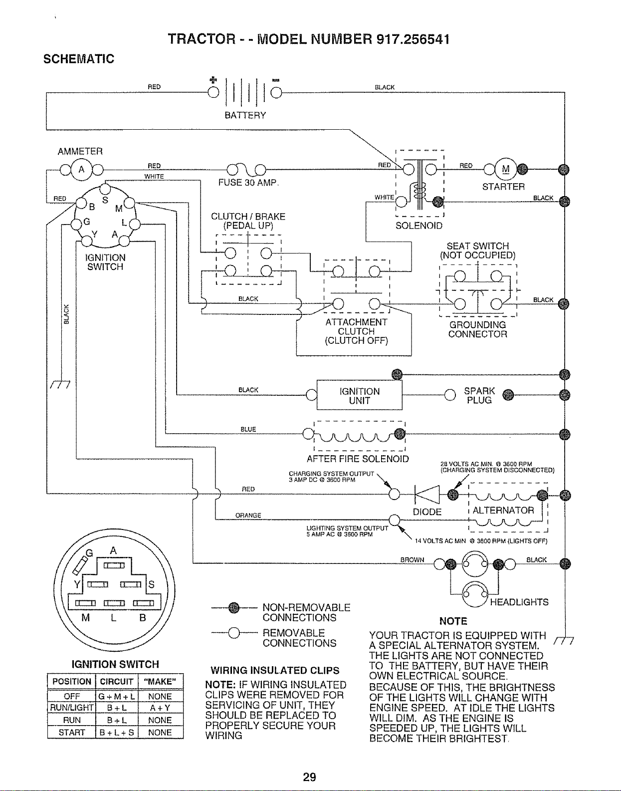
SCHEMATIC
RED
TRACTOR - - MODEL NUMBER 917.256541
BATTERY
BLACK
AMMETER
nEED
WH iTE
_,_G B MLL__
FUSE 30 AMR
I
J RED
©;
I
l STARTER
BLACK
BLACK
CLUTCH / BRAKE ...... J
(PEDAL UP) SOLENOID
BLUE
l
RED
I ........... i
AFTER FIRE SOLENOID
CHARGING SYSTEM OUTPUT
3 AMP DC @ 3600 RPM "_.
ORANGE
28 VOLTS AC MIN, e 3600 RPM
(CHARG}NG SYSTEM D_SCONNECTED)
--_---- NON-REMOVABLE
CONNECTIONS
DIODE ALTERNATOR
LtGHT_NG SYSTEM OUTP 1......... j
5 AMP AC @ 3600 RPM _ 14 VOLTS AC MIN @ 3600 RPM (LIGHTS OFF}
BROWN (__ BLACK
HEADLIGHTS
IGNITION SWITCH
POSITION
OFF
RUN/LIGHT
RUN
START
CIRCUIT "MAKE"
G+M+L NONE
B+L A+Y
B + L NONE
B + L + S NONE
REMOVABLE
CONNECTIONS
WIRING INSULATED CLIPS
NOTE: IF WIRING INSULATED
CLIPS WERE REMOVED FOR
SERVICING OF UNIT, THEY
SHOULD BE REPLACED TO
PROPERLY SECURE YOUR
WIRING
NOTE
YOUR TRACTOR IS EQUIPPED WITH
A SPECIAL ALTERNATOR SYSTEM, f
THE LIGHTS ARE NOT CONNECTED
TO THE BATTERY, BUT HAVE THEIR
OWN ELECTRICAL SOURCE.
BECAUSE OF THIS, THE BRIGHTNESS
OF THE LIGHTS WILL CHANGE WITH
ENGINE SPEED. AT IDLE THE LIGHTS
WILL DIM. AS THE ENGINE IS
SPEEDED UP, THE LIGHTS WILL
BECOME THEIR BRIGHTEST,
-7
29

30


