Loading ...
Loading ...
Loading ...
Thehex flangenuthas a right-handedthreadpattern.Donot attempt
[to forcethe nutin wrongdirection;it may damagethe nutandcreate
[a safetyhazard.
4. Placea newbladeon eachspindleso thatsideof the bladewith
part numberfacesthe groundwhenthe moweris in the operating
position.
NOTE:This baggerkit includestwo setsof blades,one set is for
the50" deckand the otheris for the54" deck.Basedonthe deck
thatyouhave, installone of the followingblade sets.The blades
can be identifiedbythe part numberstampedon eachblade:
• 50" MowingDeck, installPart No. 742-04056C
54"MowingDeck,installPart No. 742-0679
5. Securewith the hexflange nut removedearlier.Usea torque
wrenchto tightenthe hexflangenut between70 to 90 foot-
pounds.
6. Movethe woodblockto eitherthe leftor rightbladefor stabiliza-
tionand removeand replacethecenter bladeso thatsideof the
bladewith partnumberfacesthe groundwhenthe moweris in the
operatingposition.
NOTE:Savethethreebladesyoujust removedto useas replacements
orto reinstallonthebladespindleswhennotusingthe baggerkit.
installingthe Deck Baffle
NOTE: If the deckisstill flippedupsidedownwith the bladesexposed,
itmay be easiestto flip the deck backoverto completethe following
installationof the deck baffle and chutestopbracket.
1. Removetwo of the self-tappingdeckscrewson the frontrightside
of yourdeck.
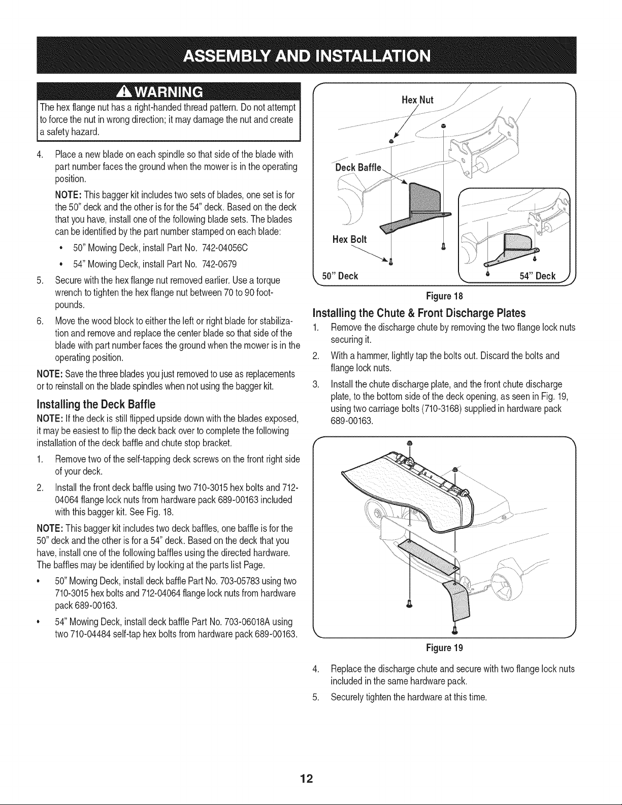
2. Installthefront deck baffle usingtwo710-3015hex boltsand 712-
04064flangelock nuts from hardwarepack689-00163included
withthisbaggerkit. See Fig. 18.
NOTE:This baggerkit includestwo deckbaffles,onebaffleisfor the
50"deckandthe otherisfor a 54"deck. Basedon thedeck that you
have,installoneof the followingbafflesusingthe directedhardware.
The bafflesmaybeidentifiedby lookingat the partslist Page.
• 50"MowingDeck,installdeck bafflePartNo.703-05783usingtwo
710-3015hexboltsand 712-04064flangelocknutsfrom hardware
pack689-00163.
• 54"MowingDeck,installdeckbafflePartNo. 703-06018Ausing
two710-04484self-taphexboltsfrom hardwarepack 689-00163.
Hex Nut
/
50" Deck
Figure 18
Installing the Chute & Front Discharge Plates
1. Removethe dischargechuteby removingthetwo flangelocknuts
securingit.
2. Witha hammer,lightlytap the boltsout. Discardthe boltsand
flangelock nuts.
3. Installthe chutedischargeplate,and the frontchutedischarge
plate,to the bottomsideof thedeckopening,as seenin Fig.19,
usingtwo carriagebolts (710-3168)suppliedin hardwarepack
689-00163.
6
Figure 19
4. Replacethe dischargechuteand securewith two flangelocknuts
includedin the samehardwarepack.
5. Securelytightenthe hardwareat thistime.
12
Loading ...
Loading ...
Loading ...