

perator's
I:RnFrSMRN°
THREE BiN BAGGER
Model No. 247.24020
• Espanol, p. 18
iMPORTANT:
Read and follow all Safety
Rules and instructions before
operating this equipment.
For answers to your questions about
this product, Call:
1-800=659=5917
Craftsman Tractor Help Line
7 am = 7 pm CT, Mort. =Sun.
Sears Brands Management Corporation, Hoffman Estates, IL 60179 U.S.A.
Visit our website: www.sears.com/craftsman FormNo.769-0%34A
(January28, 2010)

Safe Operation Practices .............................................. 3-4
Slope Guide ....................................................................... 5
Contents of Carton & Hardware Packs .......................... 6-7
Assembly and Installation ............................................ 8-14
Operation ........................................................................ 14
Parts List .................................................................... 16-17
Espa_ol ............................................................................ 18
Service Numbers ............................................. Back Cover
Craftsman Full Warranty
Ifthis Craftsmanproductfailsdueto a defectin materialor workmanshipwithinoneyearfromthe dateof purchase,returnit to any Searsstoreor
otherCraftsmanoutlet in the UnitedStatesfor free replacement.
ThiswarrantycoversONLYdefectsin materialand workmanship.Searswill NOTpayfor:
• Replacementof bags,which are expendableitemsthatcan wearoutfromnormalusewithin thewarrantyperiod.
• Repairsnecessarybecauseof accidentorfailureto operateor maintainthe productaccordingto all suppliedinstructions.
Thiswarrantyappliesforonly 90days if this productis everusedfor commercialor rentalpurposes.
Thiswarrantyappliesonly whilethisproductis usedin the UnitedStates.
Thiswarrantygivesyou specificlegalrights,and you mayalso haveotherrightswhich vary from stateto state.
Sears, Roebuck and Co., Hoffman Estates, IL 60179
© SearsBrands,LLC 2
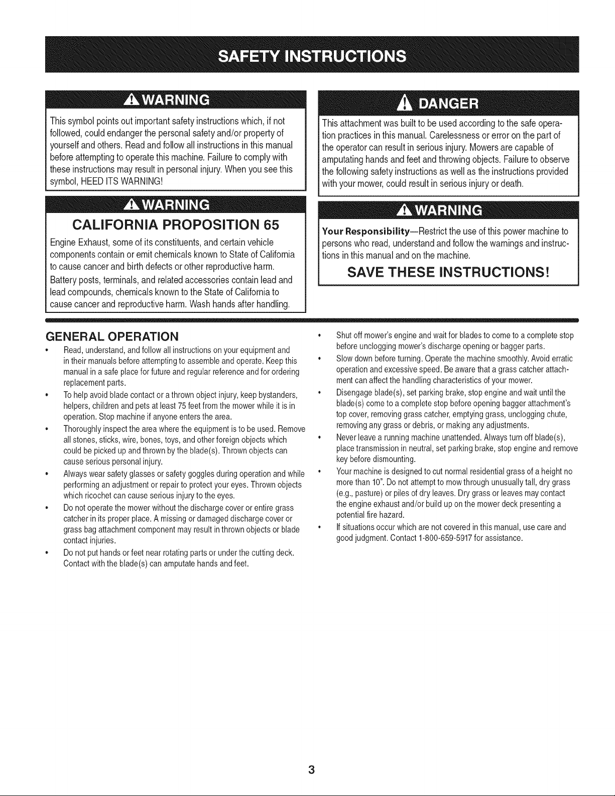
Thissymbolpointsout importantsafetyinstructionswhich,if not
followed,couldendangerthepersonalsafetyand/orpropertyof
yourselfand others. Readand followall instructionsin this manual
beforeattemptingto operatethis machine.Failureto complywith
theseinstructionsmayresultin personalinjury.Whenyou seethis
symbol,HEEDITSWARNING!
CALIFORNIA PROPOSITION 65
EngineExhaust,someof itsconstituents,andcertainvehicle
componentscontainoremitchemicalsknownto Stateof California
to cause cancerand birthdefectsor other reproductiveharm.
Batteryposts,terminals,and relatedaccessoriescontainleadand
leadcompounds,chemicalsknownto the Stateof Californiato
causecancerandreproductiveharm.Washhandsafterhandling.
Thisattachmentwas builtto be usedaccordingto the safeopera-
tion practicesin this manual.Carelessnessor error on the part of
the operatorcan resultin seriousinjury.Mowersarecapableof
amputatinghandsandfeet and throwingobjects.Failureto observe
the followingsafetyinstructionsas wellas the instructionsprovided
withyour mower,could resultin seriousinjuryor death.
Your Responsibility--Restrict the useof this powermachineto
personswho read,understandandfollow thewarningsand instruc-
tionsin thismanualand on the machine.
SAVE THESE INSTRUCTIONS!
GENERAL OPERATION
• Read,understand,and followall instructionson your equipmentand
intheir manualsbeforeattemptingto assembleand operate.Keepthis
manualina safe placefor futureand regularreferenceandfor ordering
replacementparts.
,, Tohelpavoid bladecontact ora thrown objectinjury,keepbystanders,
helpers,childrenand pets at least 75 feetfromthe mowerwhile it is in
operation.Stop machineif anyoneentersthe area.
,, Thoroughlyinspectthe area wherethe equipmentis to be used.Remove
all stones,sticks, wire, bones, toys,and other foreignobjectswhich
couldbe pickedup and thrownby the blade(s).Thrownobjects can
causeseriouspersonalinjury.
,, Alwayswearsafetyglasses or safetygogglesduringoperationand while
performinganadjustmentor repairto protectyoureyes.Thrownobjects
whichricochet can causeseriousinjury to the eyes.
,, Do not operatethe mowerwithoutthe dischargecoveror entire grass
catcherinits properplace.A missingor damageddischargecoveror
grass bagattachmentcomponentmayresult inthrownobjectsor blade
contactinjuries.
,, Do not puthands or feet near rotatingparts or underthe cutting deck.
Contactwiththe blade(s)can amputatehandsand feet.
,, Shut off mower'sengineand waitfor bladesto come to a completestop
beforeuncloggingmower'sdischargeopeningor baggerparts.
,, Slow downbeforeturning. Operatethe machinesmoothly.Avoid erratic
operationandexcessivespeed. Be awarethata grasscatcherattach-
mentcan affectthe handlingcharacteristicsof your mower.
,, Disengageblade(s),set parkingbrake,stopengineand waituntil the
blade(s)cometo a completestop beforeopeningbaggerattachment's
top cover,removinggrass catcher,emptyinggrass,uncloggingchute,
removingany grass or debris, or makingany adjustments.
,, Neverleavea runningmachineunattended.Alwaysturn off blade(s),
placetransmissionin neutral,set parkingbrake,stopengine andremove
keybeforedismounting.
,, Your machineis designedto cut normalresidentialgrassof a heightno
morethan 10".Do notattemptto mowthroughunusuallytall, dry grass
(e.g.,pasture)or pilesof dry leaves.Drygrass or leavesmay contact
the engineexhaustand/or build up on the mowerdeck presentinga
potentialfirehazard.
,, If situationsoccur whichare notcoveredinthis manual,use care and
good judgment.Contact 1-800-659-5917for assistance.
3
SLOPE OPERATION
Slopesare a majorfactor relatedto lossof control andtip-overaccidents
whichcan resultinsevere injury or death.Attachmentscan also affect the
stabilityof the machine.All slopes requireextra caution.
For yoursafety,use the slopeguideincludedas partof this manualto
estimatetheangle of slopes beforeoperatingthis machineon a slopedor hilly
area.If theslope is greaterthan 10degreesas shownon the slopeguide,do
notoperatethe mowerwiththe grass bagattachmentinstalledon that area or
seriousinjury could result.
DO:
1. Mow up anddown slopes,not across.Exerciseextremecautionwhen
changingdirection on slopes.
2. Watchfor holes,ruts,bumps,rocks,or other hiddenobjects. Uneven
terraincouldoverturnthe machine.Tall grasscan hideobstacles.
3. Useslow speed. Choosea low enoughspeedsetting sothat you will not
haveto stopor shift whileon the slope.Tires may losetractionon slopes
eventhoughthe brakesarefunctioningproperly.Alwayskeepmachine
in gear when goingdownslopesto take advantageof engine braking
action.
4. Followthe manufacturer'srecommendationsfor wheelweightsor
counterweightsto improvestability. For recommendations,contact
1-800-659-5917.
5. Keepall movementon theslopes slow and gradual.Do notmakesud-
denchangesin speedor direction.Rapidengagementor brakingcould
causethefront of the machineto lift and rapidlyflip overbackwards
whichcould causeserious injury.
6. Avoidstartingor stoppingon a slope.If tires losetraction,disengagethe
blade(s) andproceedslowly straightdownthe slope.
DO NOT:
1. Do not turn on slopesunlessnecessary;then, turn slowlyand gradually
downhill,if possible.
2. Do not mow near drop-offs,ditchesor embankments.The mowercould
suddenlyturn over if a wheel is overthe edgeof a cliff,ditch,or if an
edge caves in.
3. Do not try to stabilizethe machineby putting yourfooton the ground.
4. Do not use a grasscatcher on steepslopes.
5. Do not mow on wet grass. Reducedtractioncould causesliding.
GENERAL SERVICE
1. Beforecleaning, repairing,or inspecting,makecertainthe blade(s)
and all movingparts havestopped. Disconnectthe spark plug wireand
ground againsttheengine to preventunintendedstarting.
2. Keep all nuts, bolts,and screwstightto be surethe equipmentis in safe
workingcondition.
3. Nevertamperwith yourmower'ssafetyinterlocksystemor othersafety
devices.Checktheir properoperationregularly.
4. Neverattemptto makeadjustmentsor repairswhilethe mower'sengine
is running.
5. Grasscatchercomponentsandthe dischargecoverare subjectto wear
and damagewhichcouldexpose movingpartsor allowobjectsto be
thrown.For safetyprotection,frequentlycheckcomponentsand replace
immediatelywith originalequipmentmanufacturer's(O.E.M.)parts only,
listed inthis manual.Useof parts whichdo not meetthe originalequip-
ment specificationsmay leadto improperperformanceandcompromise
safety!
6. Maintainor replacesafetyand instructionlabels, as necessary.
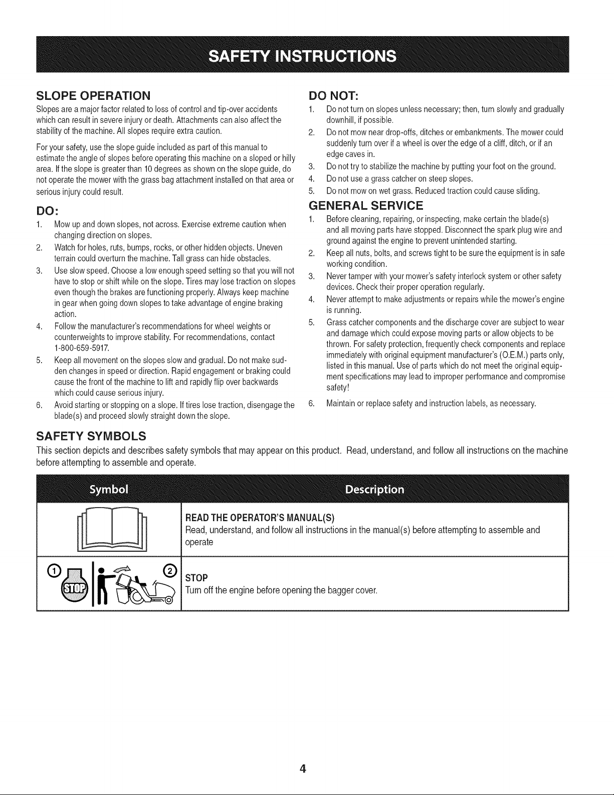
SAFETY SYMBOLS
This section depicts and describes safety symbols that may appear on this product. Read, understand, and follow all instructions on the machine
before attempting to assemble and operate.
I
I
READTHEOPERATOR'SMANUAL(S)
Read,understand,andfollowall instructionsin the manual(s)beforeattemptingto assembleand
operate
STOP
Turnoff the enginebeforeopeningthe baggercover.
4

Usethispageas a guide to determineslopeswhereyoumaynot operatesafely.Do not operate the lawnmoweron suchslopes.
0
o
Thissymbolpoints outimportantsafety instructionswhich,if not followed,could endangerthe personalsafetyand/or propertyof yourselfand
others.Readandfollow all instructionsinthis manualbeforeattemptingto operatethis machine.Failureto complywiththeseinstructionsmay
resultinpersonalinjury.Whenyou seethissymbol,HEEDITS WARNING!
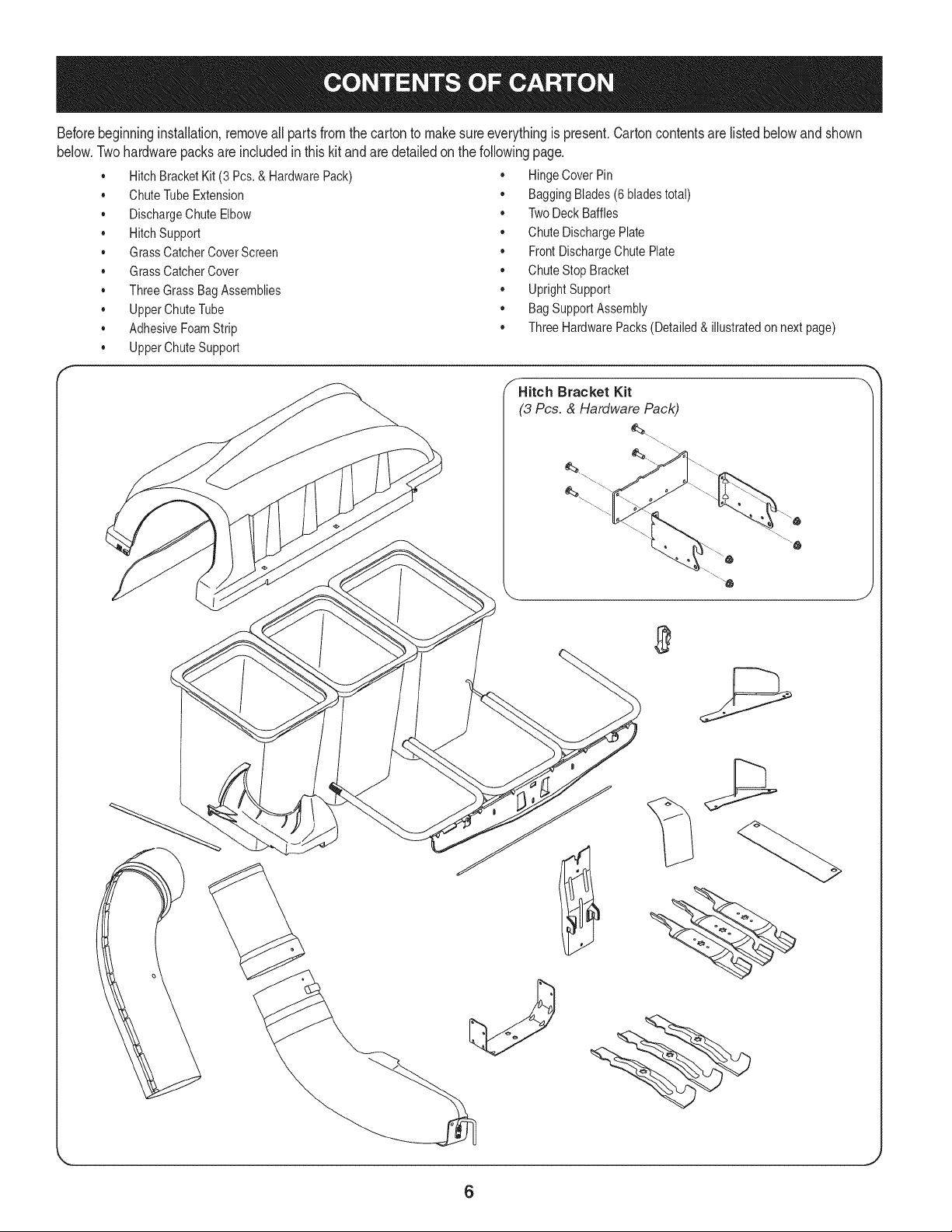
Beforebeginninginstallation,removeallpartsfromthecartontomakesureeverythingispresent,Cartoncontentsarelistedbelowandshown
below.Twohardwarepacksareincludedinthiskitandaredetailedonthefollowingpage.
• HitchBracketKit(3 Pcs.& HardwarePack) • HingeCoverPin
• ChuteTubeExtension • BaggingBlades(6 bladestotal)
• DischargeChuteElbow • TwoDeckBaffles
• HitchSupport • ChuteDischargePlate
• GrassCatcherCoverScreen • FrontDischargeChutePlate
• GrassCatcherCover • ChuteStop Bracket
• Three GrassBagAssemblies • UprightSupport
• UpperChuteTube • BagSupportAssembly
• AdhesiveFoamStrip • Three HardwarePacks(Detailed& illustratedon nextpage)
• UpperChuteSupport
_Hitch Bracket Kit
(3 Pcs. & Hardware Pack)
\
6
J
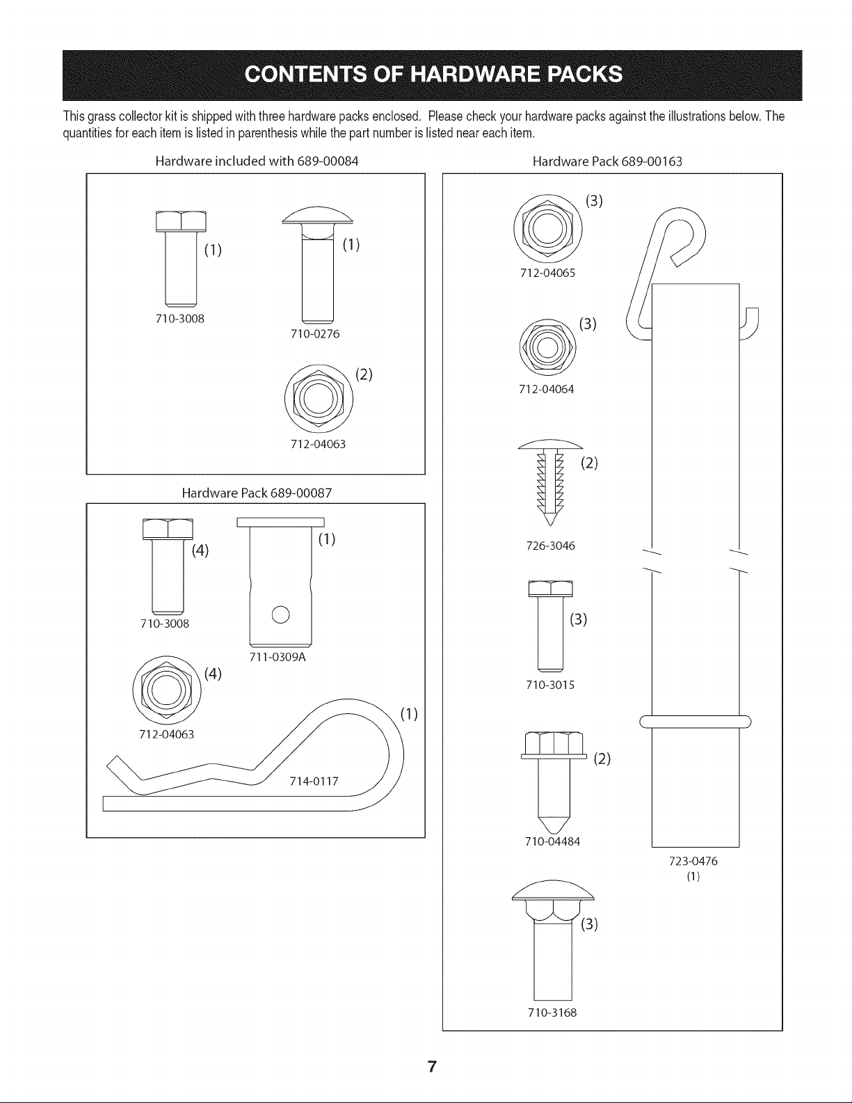
Thisgrasscollectorkit is shippedwith threehardwarepacksenclosed, Pleasecheckyourhardwarepacksagainstthe illustrationsbelow,The
quantitiesforeach itemis listedin parenthesiswhilethe part numberis listedneareachitem.
Hardware included with 689-00084 Hardware Pack689-00163
1) )
71o-3oo8
710-0276
(2)
712-04063
Hardware Pack 689-00087
710-3008
712-04063
I
©
I
(1)
711-0309A
(4)
714-0117
1)
(3)
712-04065
(3)
712-04064
(2)
726-3046
710-3015
'_' (2)
71o-o4484
' _=_(3')
710-3168
C
723-0476
(1)
7
NOTE: Referencesto left, right,front and rear of the tractorare from
theoperator'sposition,unlessotherwisestated.
• Beforeassembly,placethe tractoron a firm, levelsurface,
disengagethe PTO,stop the tractorengine and set the parking
brake.
Forconvenience,pivot the seatforwardandleaveit inthat posi-
tion untilthe grasscollectoris fully mountedand assembled.
Assemble Mounting Brackets
Toassemblethe baggermountingassembly,locatethe mounting
assemblypackandfollowthesesteps:
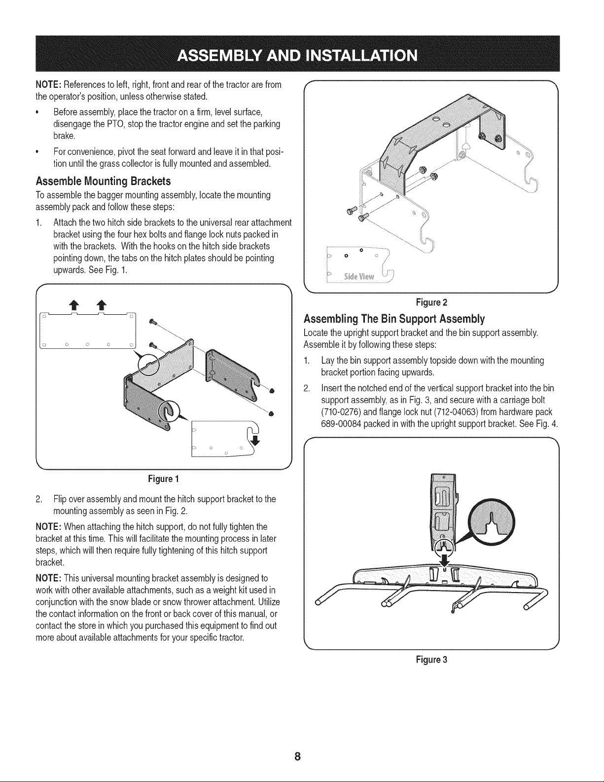
1. Attachthetwo hitch sidebracketsto the universalrearattachment
bracketusingthe fourhex boltsand flange locknutspackedin
withthe brackets.Withthe hookson the hitchsidebrackets
pointingdown,the tabsonthe hitchplatesshouldbe pointing
upwards.See Fig. 1.
0 /
/
Figure 2
Assembling The Bin Support Assembly
Locatethe uprightsupportbracketand the binsupportassembly.
Assembleit byfollowingthesesteps:
1. Laythe binsupportassemblytopsidedownwiththe mounting
bracketportionfacingupwards.
2. Insertthe notchedend of the verticalsupportbracketintothe bin
supportassembly,as in Fig.3, and securewitha carriagebolt
(710-0276)andflangelock nut (712-04063)fromhardwarepack
689-00084packedin withthe uprightsupportbracket.See Fig. 4.
Figure 1
2. Flipoverassemblyandmountthe hitchsupportbracketto the
mountingassemblyas seen in Fig.2.
NOTE:Whenattachingthe hitchsupport,do notfullytightenthe
bracketat thistime.This will facilitatethemountingprocessin later
steps,whichwillthen requirefullytighteningof this hitch support
bracket.
NOTE:This universalmountingbracketassemblyis designedto
workwithotheravailableattachments,suchas a weightkitused in
conjunctionwiththe snow bladeor snowthrowerattachment.Utilize
thecontact informationon the frontor back coverof this manual,or
contactthe storein whichyou purchasedthisequipmentto find out
moreaboutavailableattachmentsfor yourspecifictractor.
Figure 3
8
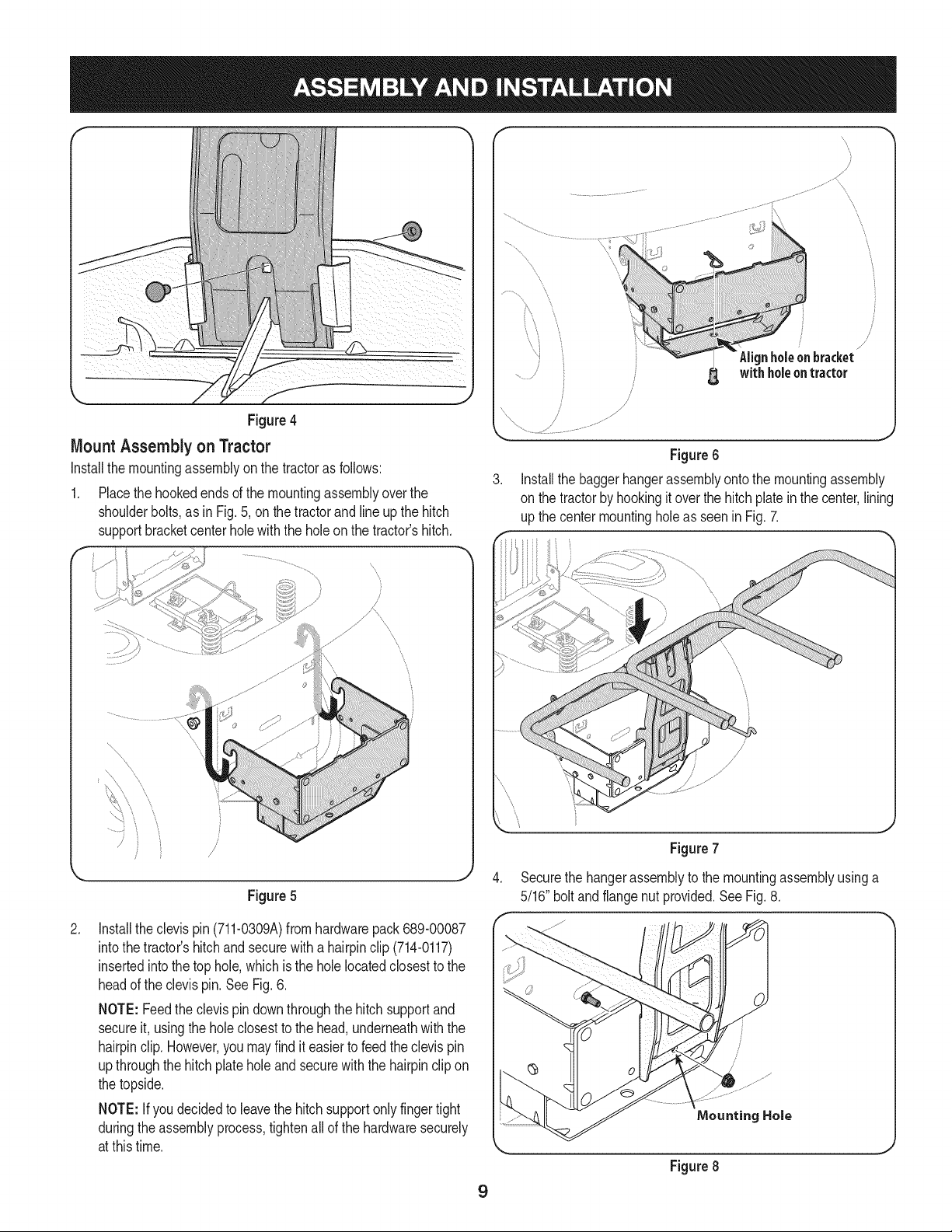
Figure4
Mount Assembly on Tractor
Installthe mountingassemblyonthe tractoras follows:
1. Placethe hookedendsof the mountingassemblyoverthe
shoulderbolts,as in Fig. 5, onthe tractorandline up the hitch
supportbracketcenter holewith the holeon the tractor'shitch.
f
...........,,
/
j
Figure5
.
Installtheclevis pin(711-0309A)fromhardwarepack 689-00087
intothe tractor'shitchand securewith a hairpinclip (714-0117)
insertedintothe top hole,whichisthe holelocatedclosestto the
headof the clevispin. SeeFig.6.
NOTE: Feedthe clevispindownthroughthehitchsupportand
secureit, usingthe holeclosestto the head,underneathwiththe
hairpinclip.However,you mayfind iteasierto feedthe clevispin
upthroughthe hitchplateholeandsecurewiththe hairpinclip on
the topside.
NOTE: If you decidedto leavethe hitchsupportonlyfingertight
duringthe assemblyprocess,tightenallof the hardwaresecurely
at this time.
, /
//
/
/
/
J
_%'_lign holeonbracket_
withholeontractor
.,J
Figure6
Installthe baggerhangerassemblyontothe mountingassembly
on the tractorby hookingitoverthe hitchplateinthe center,lining
upthe centermountingholeas seenin Fig. 7.
.
Figure7
Securethe hangerassemblyto the mountingassemblyusinga
5/16" boltand flangenut provided.See Fig. 8.
Figure8
9
Assembling Remaining Bagger Components
Nowthat themountingbracketsare assembledand are inplaceon
thetractor,followthese stepsto assemblethe remainingbagger
components.
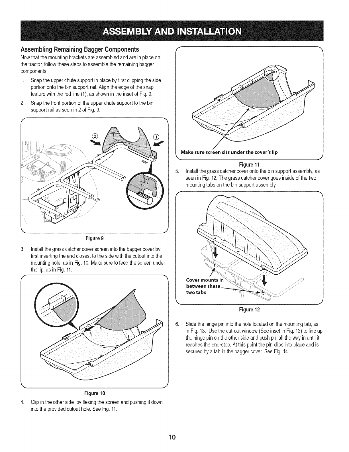
1. Snapthe upper chutesupportin placeby firstclippingthe side
portionontothe binsupportrail.Alignthe edgeof the snap
featurewiththe redline(1),as showninthe insetof Fig.9.
2. Snapthe front portionof the upperchutesupportto the bin
supportrailas seen in2 of Fig.9.
Make surescreensitsunderthe cover'slip
.J
Figure11
5. Installthe grasscatchercoverontothe bin supportassembly,as
seen in Fig. 12.The grasscatchercovergoesinsideof the two
mountingtabson the binsupportassembly.
,
Figure9
Installthegrass catchercoverscreenintothe baggercoverby
first insertingthe endclosestto the side withthe cutoutintothe
mountinghole,as inFig.10. Makesureto feedthe screenunder
the lip,as in Fig. 11.
,
Cover mounts ir
between these
two tabs
J
Figure12
Slidethe hinge pin intothe holelocatedonthe mountingtab,as
inFig. 13. Usethe cut-outwindow(Seeinsetin Fig. 13)to lineup
the hinge pin on the otherside andpushpinall the wayin until it
reachesthe end-stop.Atthis pointthe pin clips intoplaceand is
securedby a tab inthe baggercover.SeeFig. 14.
,
Figure10
Clip inthe otherside byflexingthe screenand pushingitdown
intothe providedcutouthole.SeeFig. 11.
10
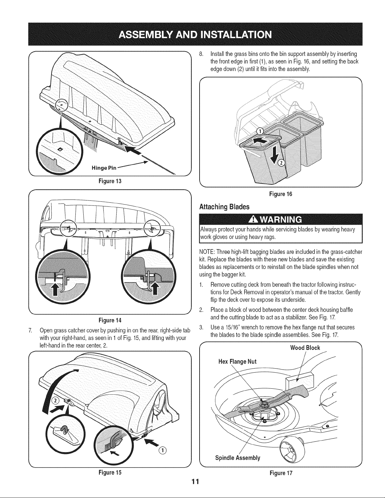
8. Installthe grass binsontothe binsupportassemblyby inserting
the front edge in first (1),as seenin Fig.16,and settingthe back
edgedown(2) until it fits intothe assembly.
Hinge Pin
!
7.
f
\
Figure13
Figure14
Opengrasscatchercover by pushingin on the rear,right-sidetab
withyourright-hand,as seenin 1 of Fig. 15,andlifting with your
left-handinthe rear center,2.
,%
Figure15
Attaching Blades
Figure16
Alwaysprotectyourhandswhileservicingbladesby wearingheavy
workglovesor usingheavyrags.
..J
NOTE:Threehigh-liftbaggingbladesare includedinthe grass-catcher
kit. Replacethe bladeswiththese newbladesandsavethe existing
bladesas replacementsorto reinstallon the bladespindleswhennot
usingthe baggerkit.
1. Removecuttingdeck from beneaththetractorfollowinginstruc-
tionsfor Deck Removalinoperator'smanualof thetractor.Gently
flip the deckoverto exposeitsunderside.
2. Placea blockof woodbetweenthe centerdeck housingbaffle
andthe cuttingbladeto actas a stabilizer.SeeFig. 17.
3. Usea 15/16"wrenchto removethe hexflangenut thatsecures
the bladesto the bladespindleassemblies.See Fig. 17.
Wood Block
Hex FlangeNut
Spindle Assembly
Figure17
11
Thehex flangenuthas a right-handedthreadpattern.Donot attempt
[to forcethe nutin wrongdirection;it may damagethe nutandcreate
[a safetyhazard.
4. Placea newbladeon eachspindleso thatsideof the bladewith
part numberfacesthe groundwhenthe moweris in the operating
position.
NOTE:This baggerkit includestwo setsof blades,one set is for
the50" deckand the otheris for the54" deck.Basedonthe deck
thatyouhave, installone of the followingblade sets.The blades
can be identifiedbythe part numberstampedon eachblade:
• 50" MowingDeck, installPart No. 742-04056C
54"MowingDeck,installPart No. 742-0679
5. Securewith the hexflange nut removedearlier.Usea torque
wrenchto tightenthe hexflangenut between70 to 90 foot-
pounds.
6. Movethe woodblockto eitherthe leftor rightbladefor stabiliza-
tionand removeand replacethecenter bladeso thatsideof the
bladewith partnumberfacesthe groundwhenthe moweris in the
operatingposition.
NOTE:Savethethreebladesyoujust removedto useas replacements
orto reinstallonthebladespindleswhennotusingthe baggerkit.
installingthe Deck Baffle
NOTE: If the deckisstill flippedupsidedownwith the bladesexposed,
itmay be easiestto flip the deck backoverto completethe following
installationof the deck baffle and chutestopbracket.
1. Removetwo of the self-tappingdeckscrewson the frontrightside
of yourdeck.
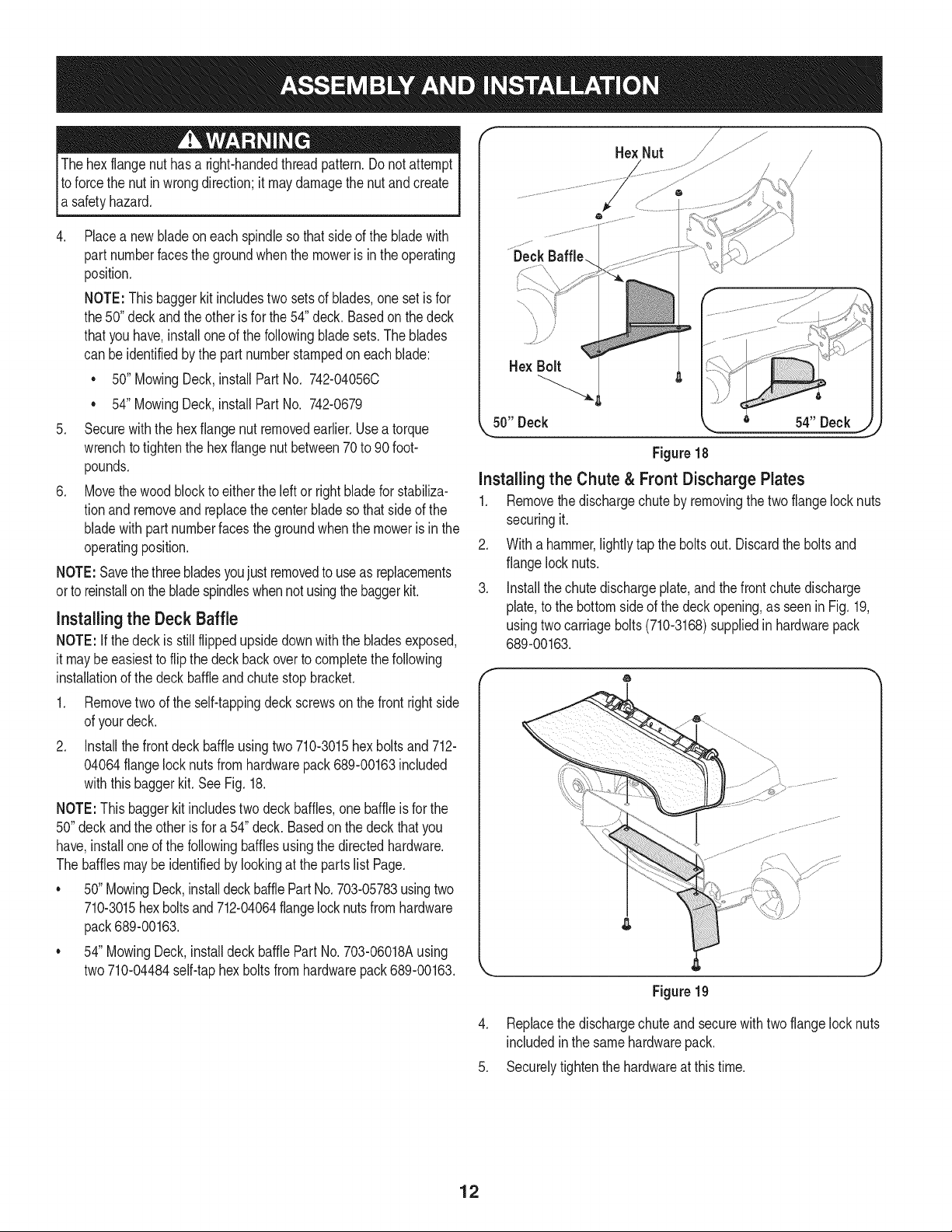
2. Installthefront deck baffle usingtwo710-3015hex boltsand 712-
04064flangelock nuts from hardwarepack689-00163included
withthisbaggerkit. See Fig. 18.
NOTE:This baggerkit includestwo deckbaffles,onebaffleisfor the
50"deckandthe otherisfor a 54"deck. Basedon thedeck that you
have,installoneof the followingbafflesusingthe directedhardware.
The bafflesmaybeidentifiedby lookingat the partslist Page.
• 50"MowingDeck,installdeck bafflePartNo.703-05783usingtwo
710-3015hexboltsand 712-04064flangelocknutsfrom hardware
pack689-00163.
• 54"MowingDeck,installdeckbafflePartNo. 703-06018Ausing
two710-04484self-taphexboltsfrom hardwarepack 689-00163.
Hex Nut
/
50" Deck
Figure 18
Installing the Chute & Front Discharge Plates
1. Removethe dischargechuteby removingthetwo flangelocknuts
securingit.
2. Witha hammer,lightlytap the boltsout. Discardthe boltsand
flangelock nuts.
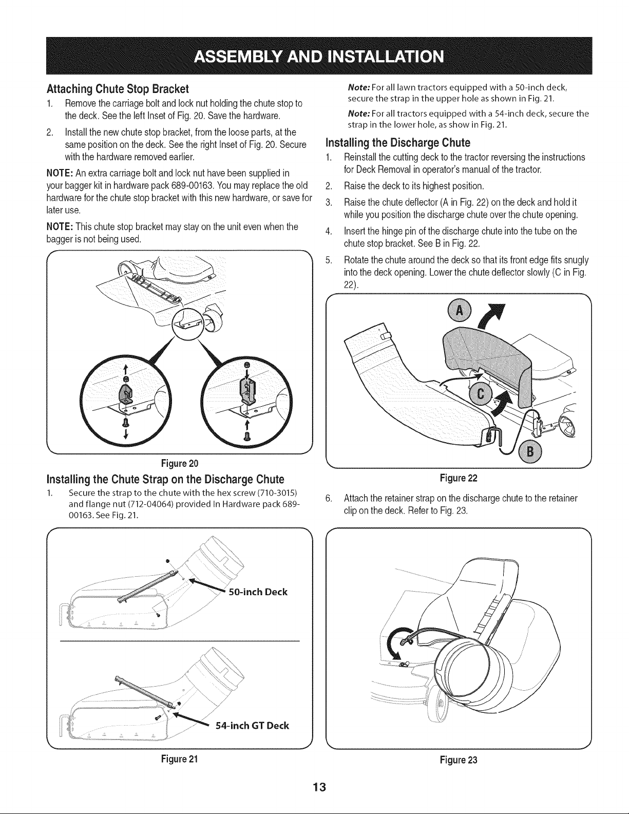
3. Installthe chutedischargeplate,and the frontchutedischarge
plate,to the bottomsideof thedeckopening,as seenin Fig.19,
usingtwo carriagebolts (710-3168)suppliedin hardwarepack
689-00163.
6
Figure 19
4. Replacethe dischargechuteand securewith two flangelocknuts
includedin the samehardwarepack.
5. Securelytightenthe hardwareat thistime.
12
Attaching Chute Stop Bracket
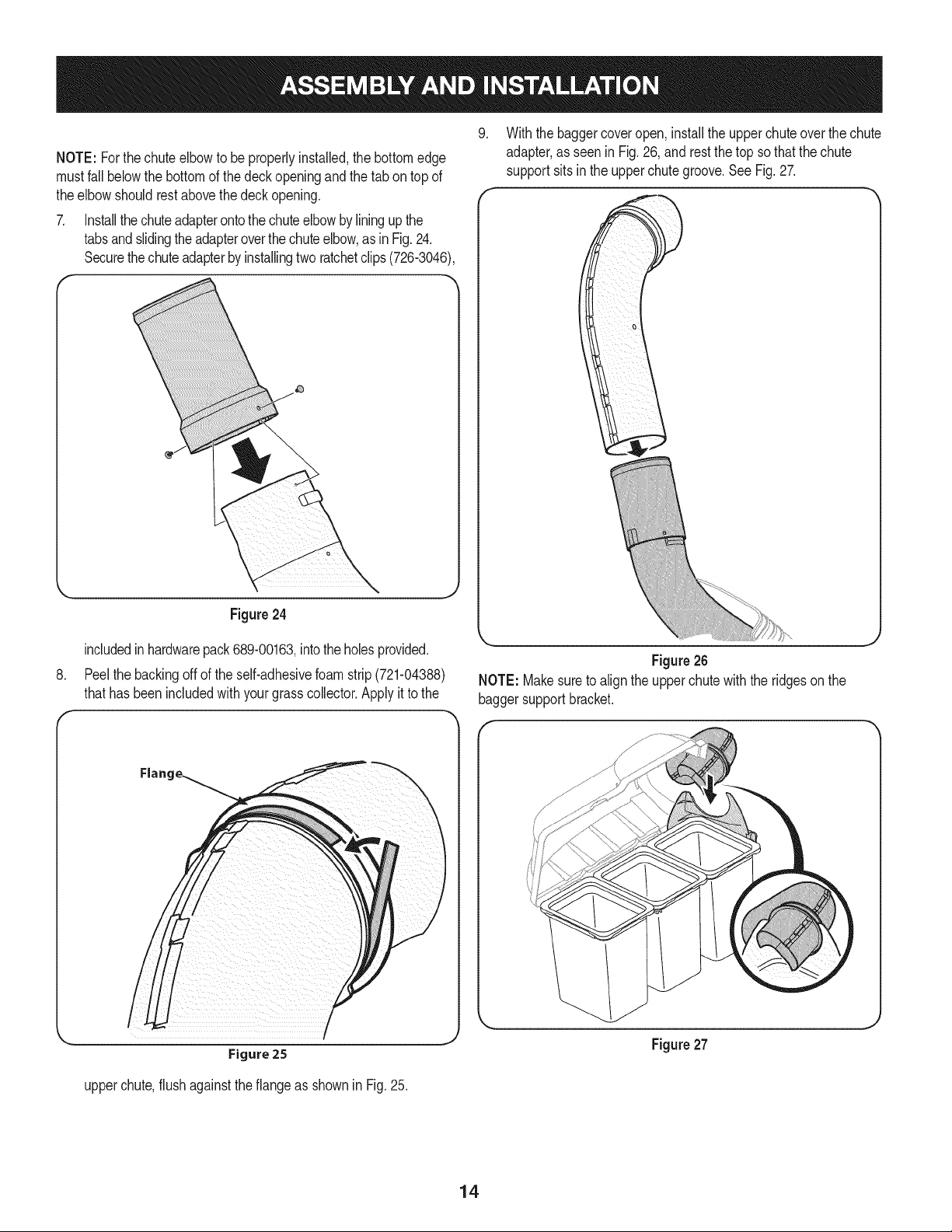
1. Removethecarriageboltand lock nutholdingthe chute stopto
the deck.Seethe left Insetof Fig.20. Savethe hardware.
2. Installthe newchutestopbracket,fromthe looseparts,at the
samepositionon thedeck. Seethe rightInsetof Fig.20. Secure
withthe hardwareremovedearlier.
NOTE:An extracarriageboltandlock nuthavebeen suppliedin
yourbaggerkit in hardwarepack689-00163.Youmay replacethe old
hardwarefor the chutestopbracketwith this newhardware,orsavefor
lateruse.
NOTE:This chute stop bracketmaystayonthe unitevenwhenthe
baggeris not beingused.
f
Figure20
Installingthe Chute Strap on the Discharge Chute
1. Secure the strap to the chute with the hex screw (710-3015)
and flange nut (712-04064) provided In Hardware pack 689-
00163. See Fig. 21.
f *-
Deck
................................................................................_ ............
, I /
< ,_ 54-inch GT Deck
k
Figure 21
Note: For all lawn tractors equipped with a 50-inch deck,
secure the strap in the upper hole as shown in Fig. 21.
Note: For all tractors equipped with a 54-inch deck, secure the
strap in the lower hole, as show in Fig. 21.
Installing the Discharge Chute
1. Reinstallthe cuttingdeckto the tractorreversingthe instructions
for DeckRemovalin operator'smanualof thetractor.
2. Raisethe deckto itshighestposition.
3. Raisethe chutedeflector(A in Fig.22) on the deckand holdit
whileyou positionthedischargechuteoverthe chuteopening.
4. Insertthe hingepinof the dischargechuteintothe tubeon the
chutestopbracket.See Bin Fig.22.
5. Rotatethechute aroundthe decksothat itsfront edgefits snugly
intothe deckopening.Lowerthe chutedeflectorslowly(C in Fig.
22).
Figure 22
Attachthe retainerstrap on the dischargechuteto the retainer
clip on the deck. Referto Fig.23.
Figure 23
_J
13
NOTE: Forthechute elbowto be properlyinstalled,thebottomedge
mustfall belowthe bottomof the deckopeningandthe tab on topof
theelbow shouldrestabovethedeckopening.
7. Installthechuteadapterontothe chuteelbowbyliningup the
tabsandslidingtheadapteroverthe chuteelbow,asin Fig.24.
Securethechuteadapterby installingtwo ratchetclips(726-3046),
Figure24
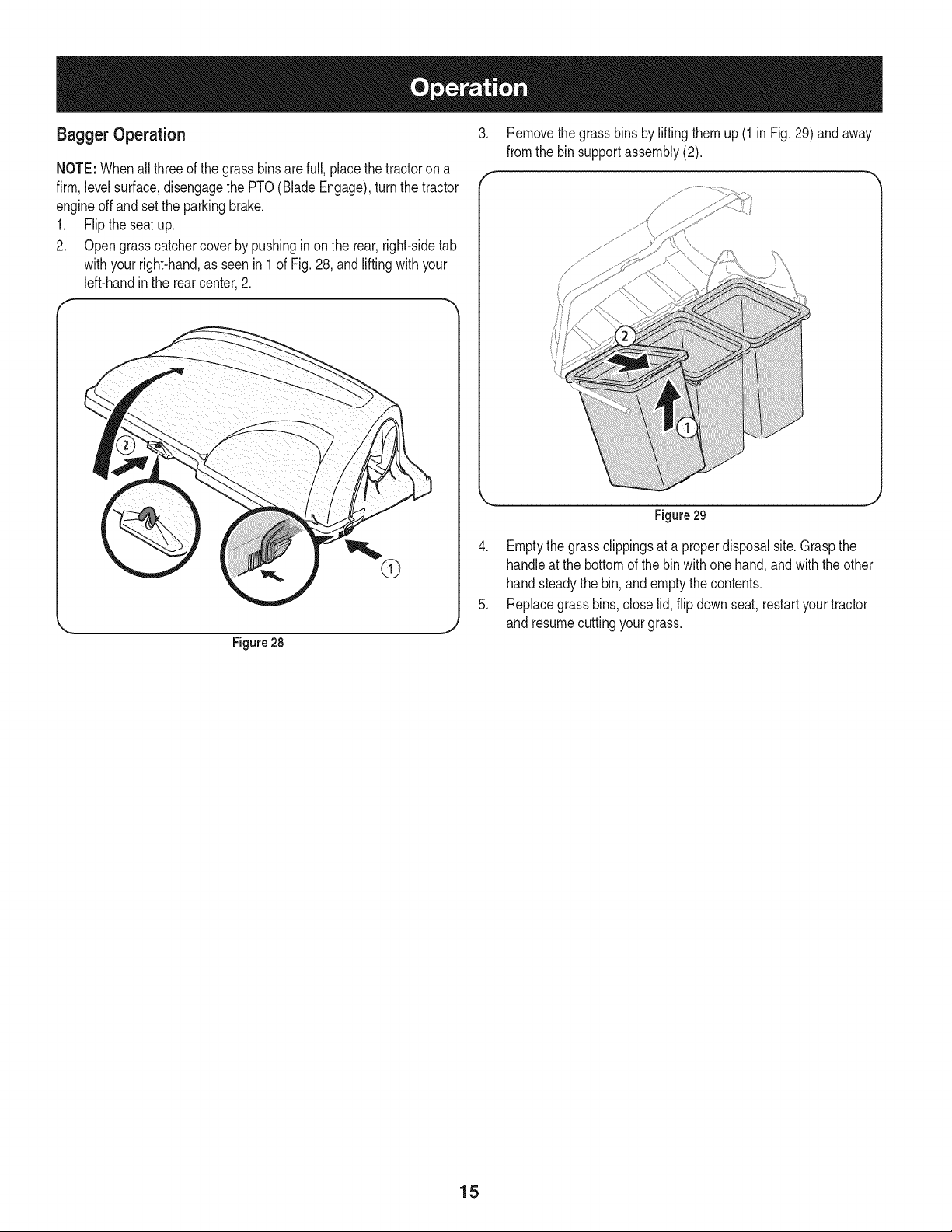
9. Withthe baggercoveropen,installtheupperchuteoverthe chute
adapter,as seen in Fig.26, andrest the top sothatthe chute
supportsitsin the upperchutegroove.See Fig.27.
.
includedin hardwarepack689-00163,intotheholesprovided.
Peelthe backingoff of the self-adhesivefoam strip (721-04388)
thathas beenincludedwithyourgrass collector.Applyit tothe
Figure 26
NOTE: Makesureto align the upperchutewiththe ridgesonthe
baggersupportbracket.
\
\
\
Figure25
upperchute,flush againstthe flangeas shownin Fig.25.
J
Figure27
14
Bagger Operation
NOTE:Whenall threeof the grassbinsare full,placethetractoron a
firm,levelsurface,disengagethe PTO(BladeEngage),turnthe tractor
engineoffand setthe parkingbrake.
1. Flipthe seatup.
2. Opengrasscatchercover by pushingin on the rear,right-sidetab
withyourright-hand,as seenin 1 of Fig. 28,and liftingwith your
left-handinthe rear center,2.
®
. J
Figure28
3. Removethe grassbinsby liftingthemup (1 in Fig. 29) and away
fromthe bin supportassembly(2).
J
Figure 29
4. Emptythe grassclippingsat a properdisposalsite.Graspthe
handleat the bottomof the binwithonehand,and with the other
handsteadythe bin, and emptythecontents.
5. Replacegrass bins,close lid, flip downseat,restartyourtractor
and resumecuttingyourgrass.
15
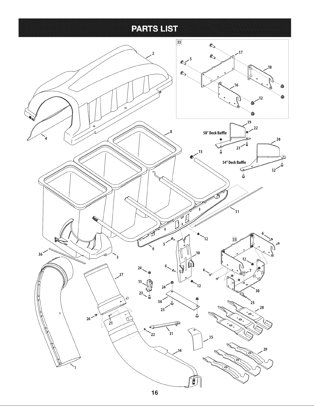
4
11
\1
3
34
1G

m
1.
2.
3.
4.
5.
6.
7.
8.
9.
10.
11.
12.
13.
14.
15.
16.
17.
18.
19.
20.
21.
22.
23.
24.
25.
26.
27.
28.
29.
30.
31.
32.
33.
34.
35.
36.
931-04291
931-04298
731-06497
731-06504
710-0276
710-3008
711-0309A
964-04096A
683-04498A
683-04519
711-05079
712-04063
735-0246A
631-04300B
683-0617A-0637
N/A*
N/A*
N/A*
703-05783-0637
703-06018A-0637
710-3015
712-04064
710-3168
712-04065
714-0117
726-3046
731-06611
742-04056C-0637
942-0679
783-05887-0637
723-0476
710-04484
689-00101
783-06418
783-06579
721-04388
UpperChuteAssembly
TripleBaggerCoverAssembly
UpperChuteSupport
BaggerCoverScreen
CarriageScrew,5/16-18x 1.00"
HexHeadScrew,5/16-18x .75"
ClevisPin, .62"Dia.
Grass-bagAssembly
TripleBag SupportAssembly
VerticalSupportBracket
CoverHingePin
FlangeLock Nut,5/16-18
EndPlug
DischargeChuteElbow,50/54"Deck
ChuteStop-Bracket
HitchBracket,RH
UniversalRearAttachmentBracket
HitchBracket,LH
DeckBaffle,50"
DeckBaffle,54"
TapScrew,1/4- 20 x .750(50"Deck)
FlangeLock Nut,1/4- 20 (50" Deck)
CarriageScrew,3/8- 16x 1.00"
FlangeLock Nut,3/8- 16
InternalCotterPin,.148x 3.00
RatchetClip,.250
BaggerChuteAdapter,7 In.
Blade,17.90Lg.,Star Bagging
Blade,18.50Lg.,High Lift
UniversalBracketSupport,RT-99/LT-5
ChuteStrap
TapScrew,5/16-18x .750(54"Deck)
MountingBracketKit (Incl.Ref.16-18)
DischargeChutePlate
FrontChuteDischargePlate
AdhesiveFoamStrip
*OrderReferenceNo.33
17

Craftsman Total Garantia
CraftsmanSi este productofalla debidoa undefectode materialo manode obradentrode un aSoa partirde la fechadecompra,el retornoa
cualquierfiendaSearso cualquierotra Craftsmande salidaenlos EstadosUnidospara la sustituci6ngratuita.
EstagaranfiacubreQnicamentedefectosde materialy manodeobra. Searsnopagar&por:
• Sustituci6ndelas bolsas,quesonfungiblesque puedenIlevara cabo apartir de la utilizaci6nnormalen el periodode
garanfia.
• Las reparacionesnecesariasa causade accidenteo el fracasoparaoperaro mantenerel productode acuerdocon todaslas
instruccionessuministradas.
Estagarantiaseaplicaa s61o90dias si esteproductoes utilizadocadavezcon finescomercialeso alquiler.
Estagaranfias61ose aplicamientraseste productose utilizaen los EstadosUnidos.
Estagaranfiale otorgaderechoslegalesespecificos,y ustedtambi_npuedetenerotros derechosque variande unestadoa otro.
Sears, Roebuck and Co., Hoffman Estates, IL 60179
© SearsBrands,LLC 18
Lapresenciadeeste sirnboloindicaque setrata de instrucciones
irnportantesde seguridadquese debenrespetarpara evitar
ponerenpeligrosu seguridadpersonaly/o materialy la de otras
personas.Lea y siga todaslas instruccionesdeestemanualantes
de poneren funcionarnientoestarn_.quina.Si no respetaestas
instruccionespodriaprovocarlesionespersonales.Cuandoveaeste
sirnbolo,ipresteatenci6na la advertencia!
PROPOSICION 65 DE CALIFORNIA
Elescapedel motordeesteproducto,algunosde suscornponentes
y algunoscornponentesdel vehiculocontieneno liberan sustancias
quirnicasqueelestadodeCaliforniaconsideraque puedenproducir
c_.ncer,defectosde nacirnientouotrosproblernasreproductivos.
Losbornesde la bateriay los accesoriosdines contienenplornoy
cornpuestosde plorno,sustanciasquirnicasque segOnIo estableci-
do pot el Estadode Californiacausancancery daSosenel sisterna
reproductivo.Ldveselas manos despu_sde estar en contacto
con estoscomponentes.
Estarn_.quinarueconstruidaparaseroperadadeacuerdocon
las reglasde seguridadcontenidasen este rnanuakAI igualque
concualquiertipo de equipo rnotorizado,undescuidoo errorpor
partedel operadorpuedeproducirlesionesgraves.Estarn_.quina
es capazde arnputarrnanosy piesy de arrojarobjetoscon gran
fuerza.Deno respetarlas instruccionesde seguridadsiguientesse
puedenproducirlesionesgraveso la rnuerte.
Su responsabilidad--Restrinja el usode esta rn_.quina
rnotorizadaa las personasque lean,cornprendany respetenlas
advertenciase instruccionesqueaparecenen este manualy en la
rn_.quina.
iGUARDEESTASINSTRUCCIONES!
Fun¢ionamiento general
1. Lea, comprenda y respete todas las instrucciones que figuran
en el equipo yen los manuales antes de intentar armarlo y
hacerlo funcionar. Guarde este manual en un lugar seguro
para consultas futuras y peri6dicas, asi como para solicitar
repuestos.
2. Para ayudar a evitar una lesi6n por contacto con las cuchillas
o con un objeto que sea arrojado, mantenga a las personas
que observan, a los ayudantes, niSos y mascotas alejados a no
menos de 25 metros de la m_quina mientras est_ funcionando.
Detenga la m_quina si alguien entra en la zona.
3. Revise minuciosamente el _rea donde se va a usar el equipo.
Retire todas las piedras, palos, cables, huesos, juguetes y otros
objetos extraSos que podrhn ser recogidos y arrojados por la
acci6n de las cuchillas. Los objetos arrojados por la m_quina
pueden causar lesiones graves.
4. Para protegerse los ojos, utilice siempre galas o lentes de
seguridad mientras opera la m_quina o mientras la ajusta
o repara. Los objetos arrojados que rebotan pueden causar
lesiones oculares graves.
5. Nunca opere la cortadora de c_sped sin tenet bien colocada
la cubierta de descarga o el colector de c_sped. Si falta o
est_ daSada la cubierta de descarga o un componente del
accesorio embolsador puede resultar en lesiones por contacto
con la cuchilla o con objetos arrojados.
6. No ponga las manos ni los pies cerca de las piezas rotatorias ni
debajo de la plataforma de corte. El contacto con las cuchillas
puede resultar en la amputaci6n de una mano o pie.
7. Apague el motor de la cortadora de c_sped y espere que
las cuchillas se detengan totalmente antes de desbloquear
la abertura de descarga de la cortadora o las piezas de la
embolsadora.
8. Reduzca la velocidad antes de girar. Opere la m_iquina de
forma pareja. Evite el funcionamiento err_itico y la velocidad
excesiva. Tenga en cuenta que el accesorio colector de c6sped
puede afectar las caracteristicas de manejo de su cortadora.
Fund0namient0 en pendientes
Las pendientes son un factor importante en los accidentes
ocasionados por p_rdida de control y vuelcos que pueden causar
lesiones graves e incluso la muerte. Los accesorios tambien pueden
afectar la estabilidad de la m_quina. La operacidn en pendiente
requiere mayor precaucidn.
Para seguridad, use el medidor de pendientes que se incluye como
parte de este manual para estimar el &ngulo de la pendiente antes
de hacer funcionar la m_iquina en una zona inclinada. Si la pendiente
es mayor a 10 grados en el medidor, no opere la cortadora con el
accesorio embolsador en ese sector, pues podria causar lesiones
graves.
Haga10siguiente:
1. Corte hacia arriba y abajo de las pendientes, no en forma
transversal. Tenga sumo cuidado al cambiar de direcci6n en
una pendiente.
2. Est_ atento a los hoyos, surcos, baches, rocas, u otros objetos
ocultos. El terreno desnivelado puede voltear la m_iquina. El
pasto alto puede ocultar obst_iculos.
3. Conduzca a baja velocidad. Elija una velocidad Io
suficientemente baja como para no tener que detenerse
o cambiar de marcha mientras est,1 en la pendiente. Los
neum_iticos pueden perder tracci6n en las pendientes aun
cuando los frenos funcionen correctamente. Mantenga
la m_iquina siempre en velocidad cuando desciende una
pendiente, para poder frenar con el motor.
19
4. Siga las recomendaciones del fabricante sobre pesos y
contrapesos de las ruedas, para mejorar la estabilidad.
5. Haga que todos los movimientos en las pendientes sean
lentos y graduales. No cambie repentinamente la velocidad
ni la direcci6n. Un frenado o cambio de velocidad repentinos
pueden causar que el frente de la m_quina se levante y d_ una
voltereta hacia atr_s, Io que podria causar lesiones graves.
6. Evite arrancar o detenerse en una pendiente. Si los neum_ticos
pierden tracci6n, desenganche las cuchillas y descienda
lentamente la pendiente.
N0 haga I0siguiente:
I. No gire en una pendiente a menos que sea imprescindible. De
ser posible, gire lenta y gradualmente cuesta abajo.
2. No corte el c_sped cerca de barrancos, zanjas o terraplenes. La
cortadora de c_sped podria volcarse repentinamente si una de
las ruedas estuviera sobre el borde de un acantilado o zanja, o
si un borde se desmoronara.
3. No intente estabilizar la m_quina poniendo el pie en el suelo.
4. No utilice un colector de c_sped en pendientes empinadas.
5. No corte el c_sped hOmedo. Una reducci6n en tracci6n puede
causar derrapes.
Servid0 general
I. Antes de limpiar, reparar o inspeccionar la m_quina,
compruebe que las cuchillas y todas las piezas m6viles se
hayan detenido. Desconecte el cable de la bujia y p6ngalo
haciendo masa contra el motor para evitar que arranque
accidentalmente.
2. Mantenga todas las tuercas, pernos y tornillos bien ajustados
para asegurarse de que el equipo est_ en condiciones seguras
de operaci6n.
3. Nunca intente violar el sistema de bloqueo de seguridad u
otros mecanismos de seguridad de la cortadora. Controle
peri6dicamente que funcionan correctamente.
4. No intente nunca hacer ajustes o reparaciones a la cortadora
mientras el motor est_ en marcha.
5. Los componentes del colector de c_sped y la cubierta de
descarga est_n sujetos a desgaste y dahos que podrian dejar
expuestas piezas que se mueven o permitir que se arrojen
objetos. Para proteger su seguridad, verifique frecuentemente
todos los componentes y reempl_celos inmediatamente
0nicamente con piezas de los fabricantes del equipo original
(O.E.M.) indicados en este manual. El uso de piezas que no
cumplen con las especificaciones del equipo original puede
resultar en rendimiento inadecuado y puede poner en peligro
la seguridad.
6. Mantenga o reemplace las etiquetas de seguridad y de
instrucciones segun sea necesario.
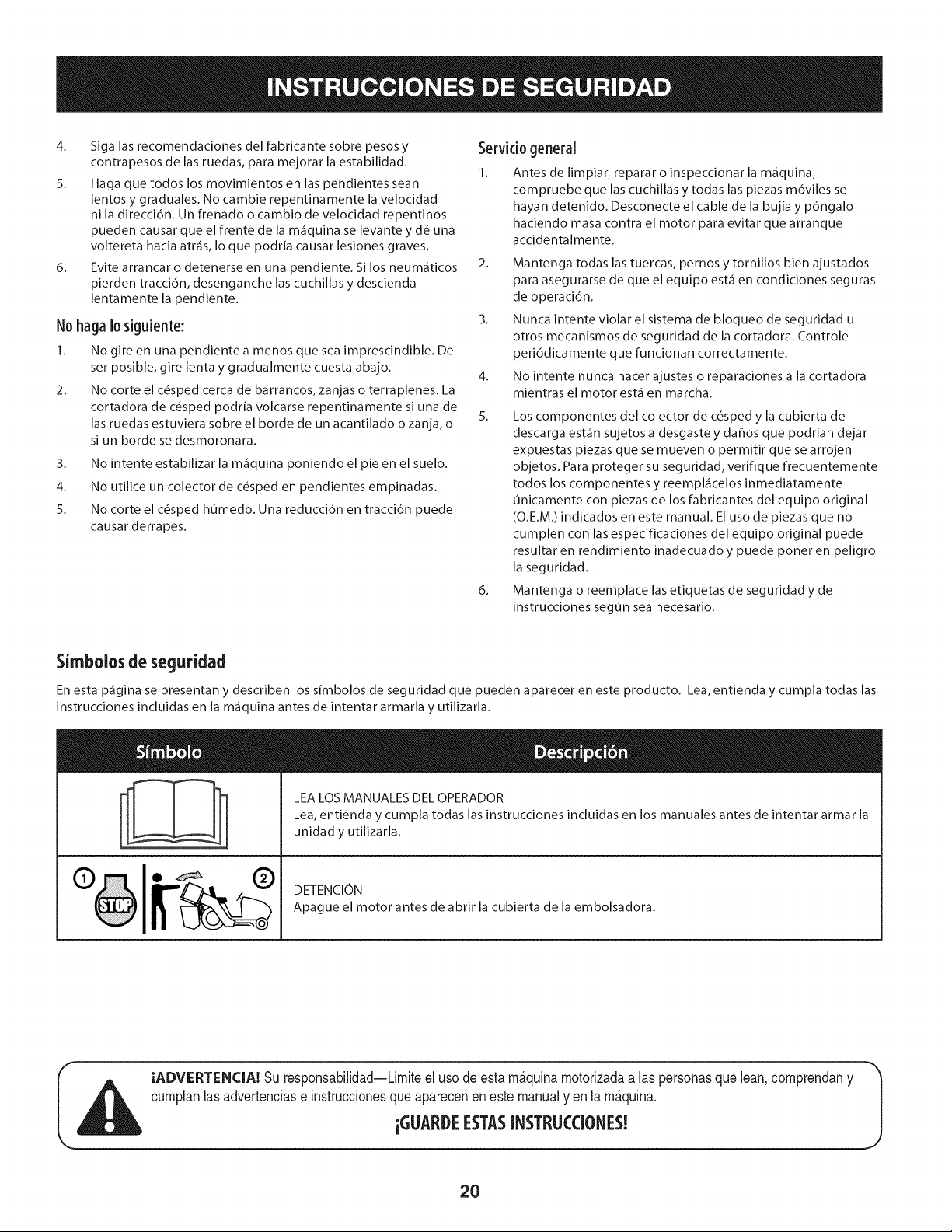
Simbolosde seguridad
En esta p_gina se presentan y describen los simbolos de seguridad que pueden aparecer en este producto. Lea, entienda y cumpla todas las
instrucciones incluidas en la m_quina antes de intentar armarla y utilizarla.
LEA LOS MANUALES DEL OPERADOR
Lea, entienda y cumpla todas las instrucciones incluidas en los manuales antes de intentar armar la
unidad y utilizarla.
DETENCION
Apague el motor antes de abrir la cubierta de la embolsadora.
IADVERTENCIA! Su responsabilidad--Limiteel usode estam_.quinamotorizadaalas personasque lean,comprendany
cumplanlasadvertenciase instruccionesque apareceneneste manualyen la m_.quina.
iGLIARDEESTASINSTRLICCIONES!
2O
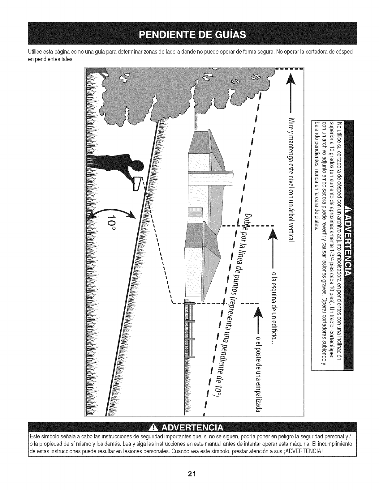
Utiliceesta p_.ginacornouna guia paradeterrninarzonasde laderadondeno puedeoperarde forrnasegura.Nooperarlacortadoradecesped
enpendientestales.
t
Estesirnbolose_alaa cabo lasinstruccionesde seguridadirnportantesque,si no se siguen,podriaponerenpeligrola seguridadpersonaly /
o la propiedadde si rnisrnoy losdern_.s.Leay siga las instruccionesen este manualantesde intentaroperarestarn_.quina.Elincurnplirniento
deestas instruccionespuede resultaren lesionespersonales.Cuandoveaeste sirnbolo,prestaratenci6na sus iADVERTENCIA!
21
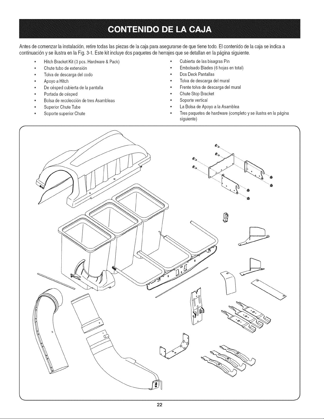
Antesdecomenzarla instalaci6n,retiretodaslas piezasdela cajapara asegurarsede que tienetodo.El contenidodela cajase indicaa
continuaci6ny se ilustraen la Fig. 3-1.Estekit incluyedos paquetesde herrajesquese detallanen la p_.ginasiguiente.
,, HitchBracketKit(3 pcs. Hardware& Pack)
,, Chutetubode extensi6n
,, Tolvade descargadel codo
,, Apoyoa Hitch
,, De cespedcubiertade lapantalla
,, Portadade cesped
,, Bolsa de recolecci6nde tres Asambleas
,, SuperiorChuteTube
,, Soportesuperior Chute
,, Cubiertade lasbisagrasPin
• EmbolsadoBlades(6 hojasen total)
,, DosDeckPantallas
,, Tolvade descargadel mural
,, Frentetolva de descargadel mural
,, ChuteStop Bracket
,, Soporte vertical
,, La Bolsa de Apoyoa la Asamblea
,, Tres paquetesde hardware(completoy se ilustraen lapagina
siguiente)
22
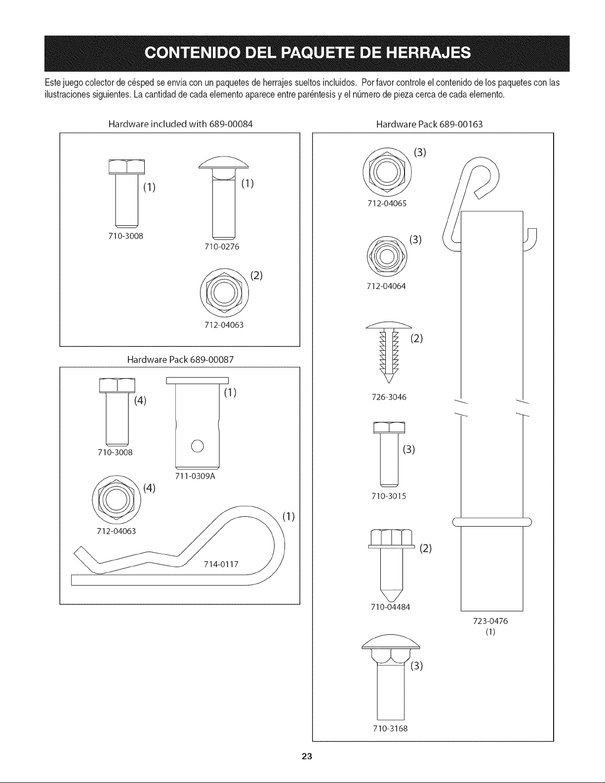
Estejuegocolectorde c_spedse enviacon unpaquetesde herrajessueltosincluidos, Porfavor controleel contenidode los paquetescon las
ilustradonessiguientes,La canfidadde cadaelementoapareceentrepar_ntesisy el nQmerode piezacercadecadaelemento,
Hardware included with 689-00084
Hardware Pack 689-00163
1) )
710-3008
710-0276
(2)
712-04063
Hardware Pack 689-00087
710-3008
712-04063
I
©
I
(1)
711-0309A
(4)
714-0117
1)
(3)
712-04065
(3)
712-04064
(2)
726-3046
710-3015
'_' (2)
71o-o4484
' _=_(3')
710-3168
C
723-0476
(1)
23
NOTA: Lasreferenciasa izquierda,derecha,partedelanteray trasera
deltractorsondesdela posici6ndeloperador,salvoindicaci6nen
contrario.
• Antesde armar,coloqueel tractorsobreuna superficiefirme
y nivelada,desenganchela toma de fuerza (PTO),detengael
motordeltractory coloqueelfreno demano.
• Paramayorcomodidad,gireel asientohaciaadelantey d_jelo
enesa posici6nhastaque el colectorde pastoest_totalmente
armadoy montado.
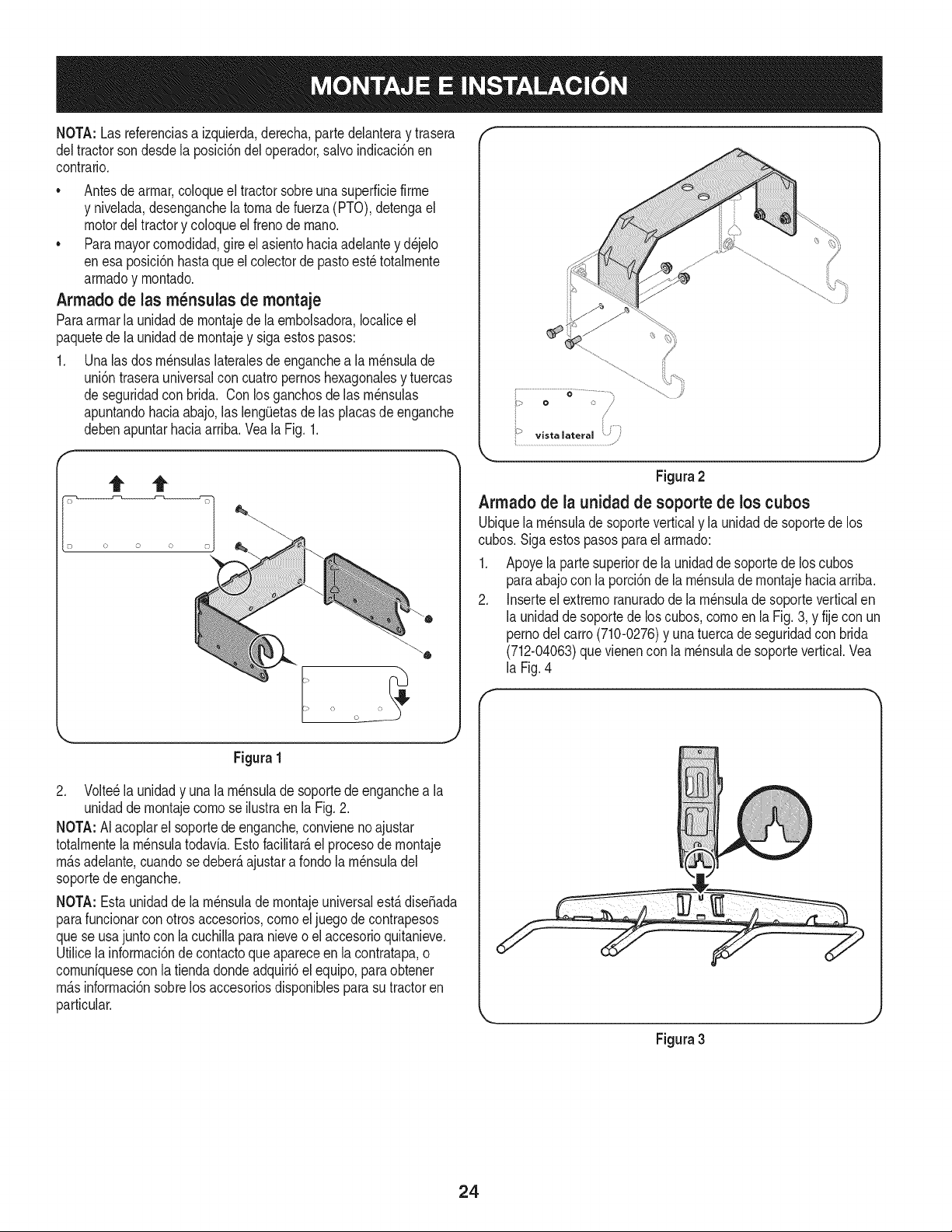
Armado de las m_nsulas de montaje
Paraarmarla unidadde montajede la embolsadora,Iocaliceel
paquetede la unidadde montajey sigaestospasos:
1. Unalas dos rn_nsulaslateralesdeenganchea la rn_nsulade
uni6ntraserauniversalcon cuatropernoshexagonalesy tuercas
de seguridadcon brida. Con losganchosde las rn_nsulas
apuntandohaciaabajo,las leng(Jetasdelas placasde enganche
debenapuntarhaciaarriba.Veala Fig.1.
Figura1
2. Volteela unidady una lam_nsuladesoportede enganchea la
unidadde montajecomose ilustraenla Fig.2.
NOTA:AI acoplarel soportede enganche,convieneno ajustar
totalmentelam_nsulatodavia.Esto facilitar_,el procesode montaje
m_.sadelante,cuandosedeber_,ajustara rondola m_nsuladel
soportedeenganche.
NOTA: Estaunidadde la m_nsulade montajeuniversalest,. dise_ada
parafuncionarcon otrosaccesorios,como el juego de contrapesos
quese usajuntocon la cuchillaparanieveo el accesorioquitanieve.
Utilicela informaci6nde contactoque apareceen la contratapa,o
comunfqueseconla tiendadondeadquiri6el equipo,paraobtener
m_.sinformaci6nsobrelosaccesoriosdisponiblesparasu tractoren
particular.
0 /
Figura2
Arrnadode la unidad de soporte de los cubos
Ubiquela rn_nsulade soporteverticaly la unidaddesoportede los
cubos.Siga estospasospara el armado:
1. Apoyela partesuperiorde launidadde soportede loscubos
paraabajocon la porci6nde la m_nsulade montajehaciaarriba.
2. Inserteel extremoranuradode la m_nsuladesoporteverticalen
la unidadde soportede loscubos,comoen la Fig.3, y fije con un
pernodelcarro(710-0276)y unatuercadeseguridadcon brida
(712-04063)que vienencon la m_nsulade soportevertical.Vea
la Fig.4
Figura3
24
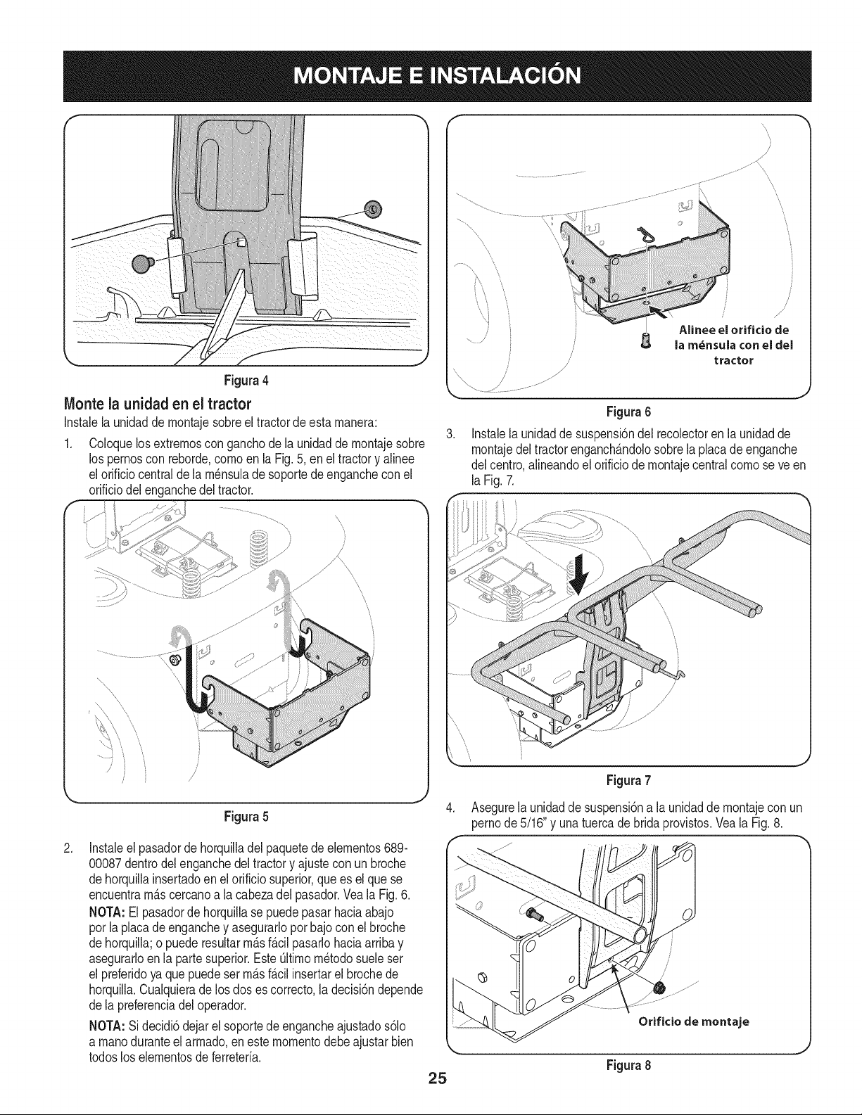
Figura 4
Monte la unidad en el tractor
Instalela unidadde montajesobreel tractordeestamanera:
Coloquelos extremoscon ganchode la unidaddemontajesobre
los pernoscon reborde,cornoen la Fig.5, en el tractory alinee
el orificiocentralde lam_nsuladesoportede enganchecon el
orificiodelenganchedel tractor.
/
............}
\
J
J
Figura 5
.
Instaleel pasadorde horquilladel paquetede elementos689-
00087dentrodel enganchedeltractory ajuste con unbroche
dehorquillainsertadoen elorificiosuperior,que es el quese
encuentram_.scercanoa la cabezadel pasador.Vea la Fig.6.
NOTA:El pasadorde horquillase puedepasarhaciaabajo
porla placade enganchey asegurarloporbajo conel broche
dehorquilla;o puede resultarm_.sf_.cilpasarlohaciaarribay
asegurarloen la partesuperior.EsteOltimom_todosuele ser
el preferidoya que puede serm_.sf_.cilinsertarel brochede
horquilla.Cualquierade losdos es correcto,la decisi6ndepende
dela preferenciadel operador.
NOTA:Si decidi6dejarel soportede engancheajustados61o
a manoduranteelarmado,en este momentodebeajustarbien
todoslos elementosde ferreteria.
.
//
/
/
/ /
J
Figura6
/
/
/
J
Alinee el orificio de
la m_nsula con el del
tractor
Instalela unidadde suspensi6ndel recolectoren la unidadde
montajedeltractorenganch_.ndolosobrela placadeenganche
del centro,alineandoel orificiode montajecentralcomose ve en
laFig.7.
Figura7
Asegurela unidadde suspensi6na la unidadde montajeconun
pernode5/16"y unatuercade bridaprovistos.Veala Fig.8.
Orifido de montaje
Figura8
25
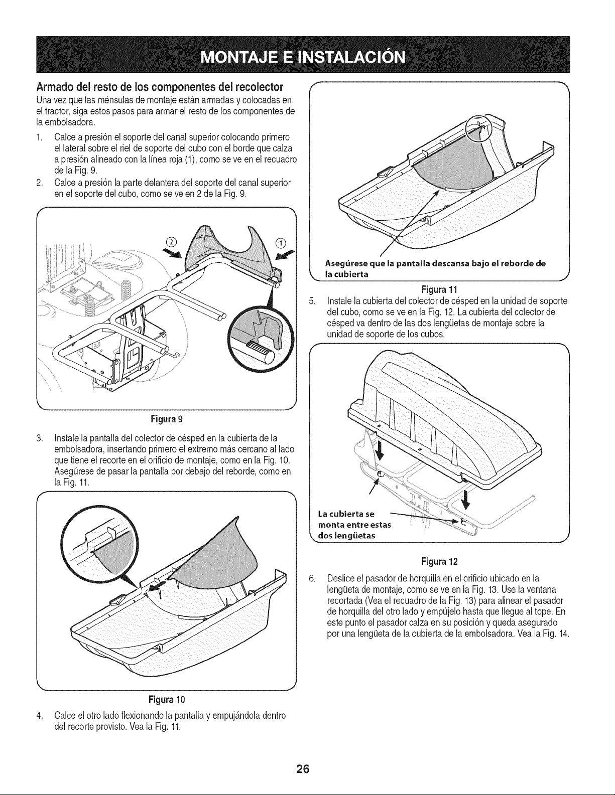
Armado del resto de los componentes dei recolector
Unavez que las rn_nsulasdernontajeest_narmadasy colocadasen
eltractor,siga estospasosparaarrnarel restode los cornponentesde
laernbolsadora.
1. Calcea presi6nel soportedel canalsuperiorcolocandoprirnero
el lateralsobreel rielde soportedel cubocon el hordeque calza
a presi6nalineadoconla linearoja (1),cornose ve en el recuadro
de laFig.9.
2. Calcea presi6nla partedelanteradel soportedel canalsuperior
enel soportedelcubo,cornose ve en 2 de la Fig. 9.
®
Aseg_reseque la pantalla descansabajo el reborde de
la cubierta
_J
Figura11
5. Instalela cubiertadelcolectorde c_speden launidadde soporte
del cubo,cornose veen la Fig.12.La cubiertadel colectorde
c_spedva dentrodelas dos lengOetasde rnontajesobrela
unidadde soportede loscubos.
,
Figura 9
Instalela pantalladel colectorde c_spedenla cubiertade la
ernbolsadora,insertandoprirneroel extrernorn_scercanoal lado
quetieneel recorteen el orificio de rnontaje,cornoen la Fig.10.
AsegOresedepasarla pantallapordebajodel reborde,cornoen
la Fig.11.
,
Figura 12
Desliceel pasadordehorquillaenel orificioubicadoenla
lengiJetade rnontaje,cornose ve en la Fig. 13.Uselaventana
recortada(Veael recuadrode la Fig. 13)para alinearel pasador
de horquilladel otrolado y ernpOjelohastaqueIlegueal tope. En
estepuntoel pasadorcalzaen su posici6ny quedaasegurado
por unalengOetade la cubiertade la ernbolsadora.Veala Fig. 14.
,
Figura 10
Calceel otrolado fiexionandola pantallay ernpuj_ndoladentro
del recorteprovisto.Veala Fig.11.
26
bisagra
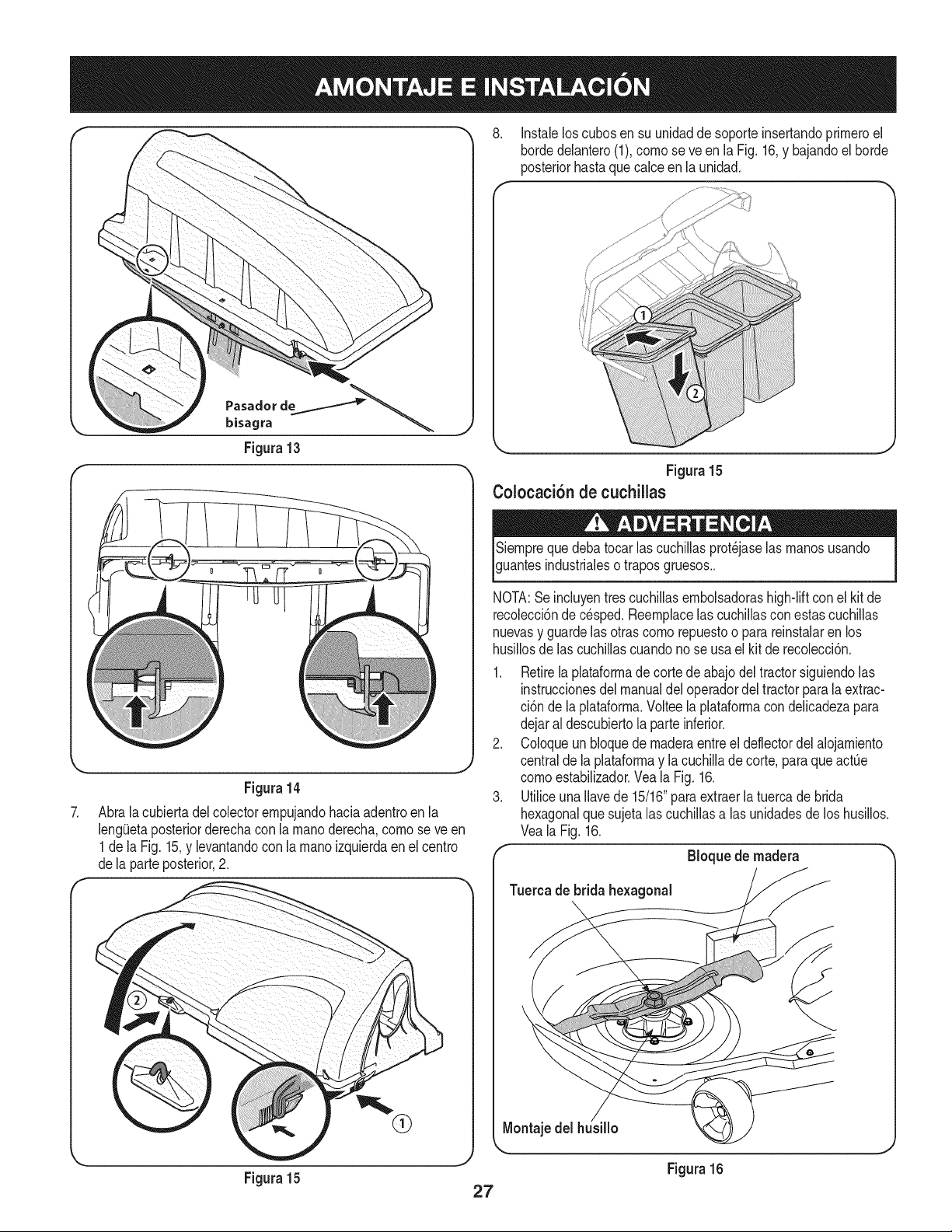
8. Instalelos cubosen su unidaddesoporteinsertandoprirneroel
hordedelantero(1),cornoseve en la Fig.16,y bajandoel horde
posteriorhastaquecalceen launidad.
f
7.
f
\
Figura 13
Figura14
Abralacubiertadel colectorernpujandohaciaadentroenla
lengQetaposteriorderechacon la rnanoderecha,cornose ve en
1dela Fig. 15,y levantandocon larnanoizquierdaenel centro
dela parteposterior,2.
,%
Figura15
Figura 15
Colocaci6n de cuchillas
uantesindustrialeso traposgruesos..
NOTA:Se incluyentrescuchillasernbolsadorashigh-liftcon elkit de
recolecci6ndec_sped.Reernplacelas cuchillasconestascuchillas
nuevasy guardelas otras cornorepuestoo para reinstalarenlos
husillosde las cuchillascuandono se usael kit de recolecci6n.
Retirelaplataforrnade cortedeabajodel tractorsiguiendolas
instruccionesdel manualdeloperadordel tractorparala extrac-
ci6n de la plataforrna.Volteela plataforrnacondelicadezapara
dejaral descubiertola parteinferior.
Coloqueun bloquede rnaderaentreel deflectordel alojarniento
centralde la plataforrnay la cuchillade corte, paraqueactQe
cornoestabilizador.Vea la Fig. 16.
Utiliceuna Ilavede 15/16"para extraerla tuerca de brida
hexagonalque sujetalas cuchillasalas unidadesde los husillos.
Veala Fig.16.
Bloque de madera
Tuereade bridahexagonal
Montaje del
Figura 16
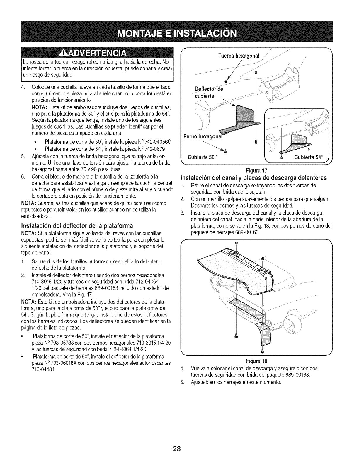
La roscade latuercahexagonalconbridagira hacia laderecha.No
intenteforzarla tuercaen ladirecci6nopuesta;puededaSarlay crear
un riesgode seguridad.
.
Coloqueuna cuchillanuevaen cadahusillode forrnaqueel lado
conel nQrnerode piezamiraal suelocuandolacortadoraest,.en
posicidndefuncionarniento.
NOTA:]Estekit de ernbolsadoraincluyedosjuegos de cuchillas,
unoparalaplataforrnade 50"y elotto paralaplataforrnade 54".
SegQnla plataforrnaquetenga,instaleunode los siguientes
juegosde cuchillas.Lascuchillasse puedenidentificarporel
nQrnerode piezaestarnpadoen cadauna:
• Plataforrnade cortede 50",instale la piezaNo742-04056C
Plataforrnade cortede 54",instalela piezaNO742-0679
5. Aj[Jstelacon la tuercade brida hexagonalque extrajoanterior-
rnente.Utiliceuna Ilavede torsi6n paraajustar la tuercade brida
hexagonalhastaentre 70 y 90 pies-libras.
6. Corrael bloquede rnaderaa la cuchillade la izquierdao la
derechapara estabilizary extraigay reernplacela cuchillacentral
deforrnaque el ladocon el n[Jrnerodepiezamireal suelocuando
lacortadoraest,.en posici6nde funcionarniento.
NOTA:Guardelastrescuchillasqueacabade quitarpara usarcorno
repuestoso parareinstalaren loshusilloscuandonose utilizala
ernbolsadora.
Instalaci6n del deflector de la plataforma
NOTA:Si la plataforrnasiguevolteadadel revesconlas cuchillas
expuestas,podriaserrn_.sf_.cilvolvera voltearlapara cornpletarla
siguienteinstalacidndel deflectorde laplataforrnay el soportedel
topede canal.
1. Saquedos de los tornillosautorroscantesdel lado delantero
derechode la plataforrna
2. Instaleel deflectordelanterousandodos pernoshexagonales
710-30151/20y tuercasde seguridadconbrida 712-04064
1/20del paquetedeherrajes689-00163incluidoconestekit de
ernbolsadora.Veala Fig.17.
NOTA: Estekit de ernbolsadoraincluyedosdeflectoresde la plata-
forrna,unoparala plataforrnade 50"y el otro parala plataforrnade
54".SegQnla plataforrnaquetenga,instale unode estosdefiectores
con los herrajesindicados.Losdeflectoressepuedenidentificaren la
p_.ginade lalista de piezas.
• Plataforrnade cortede 50",instaleel deflectorde la plataforrna
piezaNO703-05783con dospernoshexagonales710-30151/4-20
y lastuercasde seguridadconbrida 712-040641/4-20.
• Plataforrnade cortede 50",instaleel deflectorde la plataforrna
piezaNO703-06018Acon dospernoshexagonalesautorroscantes
710-04484.
Tuercahexagonal //;
De
cubierta
Cubierta 50"
Figura 17
Instalaci6n del canal y placas de descarga delanteras
1. Retireel canalde descargaextrayendolas dos tuercasde
seguridadcon bridaque Iosujetan.
2. Con un rnartillo,golpeesuavernentelos pernospara quesalgan.
Descartelos pernosy lastuercasde seguridad.
3. Instalela placade descargadelcanaly la placade descarga
delanteradel canal, haciala parteinferiorde la aberturadela
plataforrna,cornoseve en la Fig.18,con dos pernosdecarrodel
paquetede herrajes689-00163.
Figura 18
4. Vuelvaa colocarel canalde descargay aseg[Jrelocon dos
tuercasde seguridadcon bridadel paquete689-00163.
5. Ajustebienlosherrajesen esternornento.
28
JnstaJaci6n deJ soporte del tope de canaJ
1. Retireel pernode carroy tuercade seguridadque sujetanel tope
decanala la plataforma.Veael recuadroizquierdode la Fig.lg.
Guardelos herrajes.
2. De las piezassueltas,instaleel nuevosoportedel topede canal
enla mismaposicbn en la plataforma.Veael recuadroderecho
dela Fig.19.Fijecon losherrajesque retir6anteriormente.
NOTA:En el paquetede herrajes689-00163del kitde embolsadora
encontrar_,unpernode carroy unatuerca de seguridadadicionales.
Puedereemplazarlos herrajesantiguosdel soportedel topede canal,
o guardarlosparausarlosm_.sadelante.
NOTA:El soportedel topede canalpuedequedaren la unidad
aunquenose utilice la embolsadora.
Figura 19
Instalaci6n de la correa de la Chute en la tolva de
descarga
1. Asegurela correaa la tolvacon el tornilJohexagonaly tuerca
bridasiempreen packde hardware68g-00163.V6asela figura.
20.
f --
50-inch Deck
/,
NOATA:Paratodos los tractoresdejardinequipadoconun
paquetede 50-pulgadas,segurode lacorreaen el orificiode la
partesuperiorcomose muestraen la figura.20.
NOTA:Paratodos lostractoresequipadoscon unabarajade
54 pulgadas,segurode la correaen la parteinferiordel agujero,
comose muestraen lafigura.20.
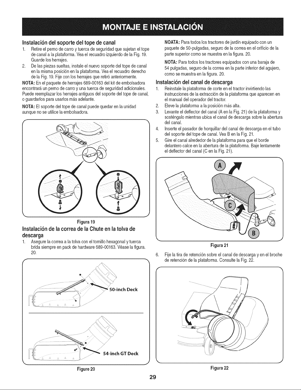
Instalaci6n del canaJ de descarga
1. Reinstalela pJataformadecorteen el tractorinvirtiendolas
instruccionesde laextracci6nde la plataformaque aparecenen
el manualdel operadordel tractor.
2, Elevela plataformaa laposicbn m_.salta,
3, Levanteel deflectordel canal(A en la Fig.21) de la plataformay
sost6ngalomientrasubicaelcanalde descargasobrela abertura
del canal,
4, Jnserteel pasadordehorquillardel canalde descargaenel tubo
del soportedeltopede canal.VeaBen la Fig.21,
5, Gireel canalalrededorde la plataformaparaqueel borde
delanterocalce en la aberturade la plataforma,Bajelentamente
el deflectordel canal (C en la Fig, 21),
,J
Figura 21
Fijela tirade retenci6nsobreel canalde descargayen el broche
de retenci6nde laplataforrna.Consultela Fig.22.
Figura 22
29
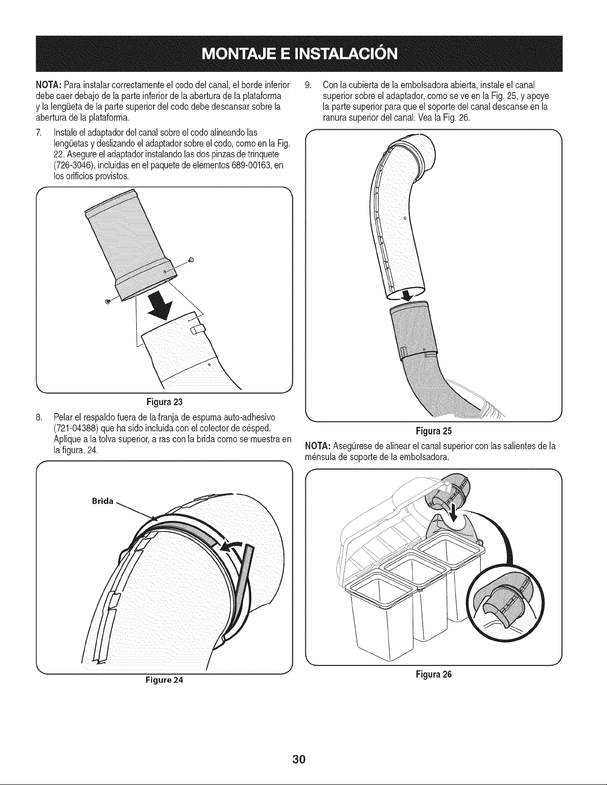
NOTA: Parainstalarcorrectamenteelcodo delcanal,el bordeinferior
debecaer debajode la parte inferiorde la aberturade la plataforma
y la leng(Jetade la partesuperiordel cododebedescansarsobrela
aberturade la plataforma.
Instaleel adaptadordel canalsobreel codoalineandolas
leng0etasy deslizandoel adaptadorsobreel codo,comoen la Fig.
22.Asegureel adaptadorinstalandolasdospinzasde trinquete
(726-3046),incluidasenel paquetedeelementos689-00163,en
losorificiosprovistos.
,
Con la cubierta de la embolsadoraabierta,instaleel canal
superiorsobreel adaptador,comose ve enla Fig.25, y apoye
la partesuperiorparaque el soportedel canaldescanseen la
ranurasuperiordel canal.Vea la Fig.26.
,
Figura 23
Pelarel respaldofuerade lafranjade espurnaauto-adhesivo
(721-04388)que hasidoincluidaconel colectorde c_sped.
Apliquea latolvasuperior,a ras conla bridacomose muestraen
lafigura.24.
Figura 25
NOTA: Aseg_resede alinearel canal superiorcon lassalientesde la
m_nsulade soportede laembolsadora.
Brida
Figure 24
J
Figura 26
30
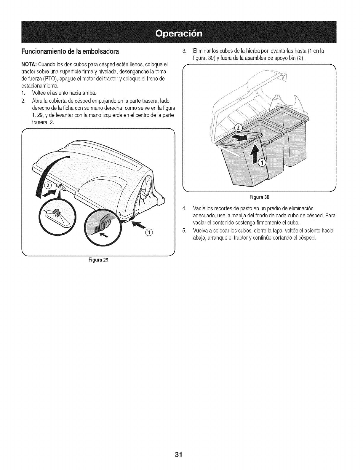
Funcionamientode la embolsadora
NOTA:Cuandolosdos cubospara cespedest_n lenos, coloqueel
tractorsobreuna superficiefirrney nivelada,desenganchela torna
defuerza(PTO),apagueel motordeltractory coloqueelfrenode
estacionarniento.
1. Volt,eel asientohaciaarriba.
2. Abralacubiertade cespedernpujandoen laparte trasera,lado
derechode la ficha con su rnanoderecha,cornose veen la figura
1.29, y de levantarcon la rnanoizquierdaen elcentrode la parte
trasera,2.
3. Elirninarlos cubosdela hierbaporlevantaflashasta(1en la
figura.30)y fuerade la asarnbleade apoyobin (2).
f
Figura30
4. Vacielos recortesde pastoen un prediode elirninaci6n
adecuado,use larnanijadel rondode cadacubode c_sped.Para
vaciarel contenidosostengafirrnernenteelcubo.
5. Vuelvaa colocar loscubos,cierrela tapa,volt_eel asientohacia
abajo,arranqueel tractory continOecortandoel c_sped.
Figura 29
31

Your Home
For troubleshooting, product manuals and home solutions advice:
÷anag÷
www.managemyhome.com
For repair - in your home - of all major brand appliances,
lawn and garden equipment, or heating and cooling systems,
no matter who made it, no matter who sold it!
For the replacement parts, accessories and
owner's manuals that you need to do-it-yourself.
For Sears professional installation of home appliances
and items like garage door openers and water heaters.
1-800-4-MY-HOME ® (1-800-469-4663)
Call anytime, day or night (U.S.A. and Canada)
www.sears.com www.sears.ca
Our Home
For repair of carry-in items like vacuums, lawn equipment,
and electronics, call anytime for the location of your nearest
Sears Parts & Repair Service Center
1-800-488-1222 (U.S.A.) 1-800-469-4663 (Canada)
www.sears.com www.sears.ca
To purchase a protection agreement on a product serviced by Sears:
1-800-827-6655 (U.S.A.) 1-800-361-6665 (Canada)
Para pedir servicio de reparaci6n Au Canada pour service en fran£ais:
a domicilio, y para ordenar piezas: 1-800-LE-FOYER Mc
1-888-SU-HOGAR ® (1-800-533-6937)
(1-888-784-6427) www.sears.ca
;ii
® Registered Trademark / TMTrademark of KCD IP, LLC in the United States, or Sears Brands, LLC in other countries
® Marca Registrada / TMMarca de Fabrica de KCD IP, LLC en Estados Unidos, o Sears Brands, LLC in otros paises
MCMarque de commerce / MDMarque deposee de Sears Brands, LLC