

perator's
I:RnFrSMRN°
TWO BiN BAGGER
Model No. 247.240192
• Espanol, p. 18
iMPORTANT:
Read and follow all Safety
Rules and instructions before
operating this equipment.
For answers to your questions about
this product, Call:
1-800=659=5917
Craftsman Tractor Help Line
7 am = 7 pm CT, Mort. =Sun.
Sears Brands Management Corporation, Hoffman Estates, IL 60179 U.S.A.
Visit our website: www.craftsman.com FormNo.769-05633G
(November27,2012)

Safe Operation Practices ..........................................................3-4
Slope Guide ......................................................................................5
Contents of Carton & Hardware Packs ................................6-7
Assembly and Installation .....................................................8-14
Operation ........................................................................................15
Parts List .....................................................................................16-17
Espa_ol .............................................................................................18
CRAFTSMAN ONE YEAR FULL WARRANTY
FORONEYEARfromthe dateof purchase,this productiswarrantedagainstanydefectsin materialor workmanship.Adefectiveproductwill bereplacedfreeof
charge.
Forwarrantycoveragedetailsto obtainfreereplacement,visit thewebsite:www.craftsman.com
Thiswarrantyisvoidifthisproductiseverusedwhile providingcommercialservicesor if rentedto anotherperson.
Thiswarrantygivesyouspecificlegalrights,andyoumayalsohaveotherrightswhichvaryfrom stateto state.
SearsBrandsManagement, H0ffman Estates,IL 60179
© SearsBrands,LLO 2
Thissymbolpointsout importantsafetyinstructionswhich,if not
followed,couldendangerthepersonalsafetyand/orpropertyof
yourselfand others. Readand followall instructionsin this manual
beforeattemptingto operatethis machine.Failureto complywith
theseinstructionsmayresultin personalinjury.Whenyou seethis
symbol,HEEDITSWARNING!
CALIFORNIA PROPOSITION 65
EngineExhaust,someof itsconstituents,andcertainvehicle
componentscontainoremit chemicalsknownto Stateof California
to causecancerand birthdefects or other reproductiveharm.
Batteryposts,terminals,and relatedaccessoriescontainleadand
leadcompounds,chemicalsknownto the Stateof Californiato
causecancerandreproductiveharm.Washhandsafterhandling.
Thisattachmentwas builtto be usedaccordingto the safeopera-
tion practicesin this manual.Carelessnessor error onthe part of
the operatorcan resultin seriousinjury.Mowersarecapableof
amputatinghandsandfeetandthrowingobjects.Failureto observe
the followingsafetyinstructionsas wellas the instructionsprovided
withyour mower,could resultin seriousinjuryor death.
Your Responsibility--Restrict the useof thispowermachineto
personswho read,understandandfollowthewarningsand instruc-
tionsin thismanualand on the machine.
SAVE THESE INSTRUCTIONS!
GENERAL OPERATION
,, Read,understand,and followall instructionson your equipmentand
intheir manualsbeforeattemptingto assembleand operate.Keepthis
manualina safe placefor futureand regularreferenceandfor ordering
replacementparts.
,, Tohelp avoid bladecontact or a thrown objectinjury,keepbystanders,
helpers,childrenand pets at least 75 feetfrom the mowerwhile itis in
operation.Stop machineif anyoneentersthe area.
,, Thoroughlyinspectthe areawherethe equipmentis to be used.Remove
all stones,sticks, wire, bones, toys,and other foreignobjectswhich
couldbe pickedup and thrownby the blade(s). Thrownobjects can
causeseriouspersonalinjury.
,, Alwayswearsafetyglasses or safetygogglesduringoperationand while
performinganadjustmentor repairto protectyoureyes. Thrownobjects
whichricochet can causeseriousinjuryto the eyes.
,, Do not operatethe mowerwithoutthe dischargecoveror entire grass
catcherinits properplace.A missingor damageddischargecoveror
grass bagattachmentcomponentmayresult inthrown objectsor blade
contactinjuries.
,, Do not puthands or feet near rotatingparts or underthe cutting deck.
Contactwiththe blade(s) can amputatehandsand feet.
,, Shut off mower'sengineand waitfor bladesto come to a completestop
beforeuncloggingmower'sdischargeopeningor baggerparts.
,, Slow downbeforeturning. Operatethe machinesmoothly.Avoid erratic
operationandexcessivespeed. Be awarethat a grasscatcher attach-
mentcan affectthe handlingcharacteristicsof your mower.
,, Disengageblade(s),set parkingbrake,stop engineand waituntil the
blade(s)cometo a completestop beforeopeningbaggerattachment's
top cover,removinggrass catcher,emptyinggrass,uncloggingchute,
removingany grass ordebris, or makingany adjustments.
,, Neverleavea runningmachineunattended.Alwaysturn off blade(s),
placetransmissionin neutral,set parkingbrake,stopengine andremove
keybeforedismounting.
,, Your machineis designedto cut normalresidentialgrassof a heightno
morethan 10".Do notattemptto mowthrough unusuallytall, dry grass
(e.g.,pasture)or pilesof dry leaves.Drygrass orleaves maycontact
the engineexhaustand/or build up on the mowerdeckpresentinga
potentialfirehazard.
,, If situationsoccur whichare not coveredin this manual,use care and
good judgment.
3
SLOPE OPERATION
Slopesare a majorfactor relatedto lossof controlandtip-overaccidents
whichcan resultinsevere injury or death.Attachmentscan also affect the
stabilityof the machine.All slopesrequireextra caution.
For yoursafety,use the slopegauge includedas part of this manualto
estimatetheangle of slopesbeforeoperatingthis machineon a slopedor hilly
area.If theslope is greaterthan 10degreesas shownon the slopeguide,do
notoperatethe mowerwiththe grass bagattachmentinstalledonthat area or
seriousinjury could result.
DO:
1. Mow up anddown slopes,not across.Exerciseextremecautionwhen
changingdirection on slopes.
2. Watchfor holes,ruts,bumps,rocks,or otherhiddenobjects. Uneven
terraincouldoverturnthe machine.Tall grasscan hideobstacles.
3. Useslow speed. Choosea low enoughspeedsetting sothat you will not
haveto stopor shift whileon the slope.Tires may losetractionon slopes
eventhoughthe brakes arefunctioningproperly.Alwayskeepmachine
in gear when goingdownslopesto take advantageof engine braking
action.
4. Followthe manufacturer'srecommendationsfor wheelweights or
counterweightsto improvestability.
5. Keepall movementon theslopes slow and gradual.Do notmakesud-
denchanges in speedor direction.Rapidengagementor brakingcould
causethe front of the machineto lift and rapidlyflip overbackwards
whichcould causeserious injury.
6. Avoidstartingor stoppingon a slope.If tires losetraction,disengagethe
blade(s) andproceedslowly straightdownthe slope.
DO NOT:
1. Do not turn on slopesunlessnecessary;then, turn slowlyand gradually
downhill,if possible.
2. Do not mow near drop-offs,ditchesor embankments.The mowercould
suddenlyturn over if a wheel is overthe edgeof a cliff,ditch, or if an
edge caves in.
3. Do not try to stabilizethe machineby putting yourfooton theground.
4. Do not use a grasscatcher on steepslopes.
5. Do not mow on wet grass. Reducedtractioncould causesliding.
GENERAL SERVICE
1. Beforecleaning, repairing,or inspecting,makecertainthe blade(s)
and all movingparts havestopped. Disconnectthe spark plugwireand
ground againsttheengine to preventunintendedstarting.
2. Keep all nuts, bolts,and screwstightto be surethe equipmentis in safe
workingcondition.
3. Nevertamperwith yourmower'ssafetyinterlocksystemor othersafety
devices.Checktheir properoperationregularly.
4. Neverattemptto makeadjustmentsor repairswhile themower'sengine
is running.
5. Grasscatcher componentsandthe dischargecoverare subjectto wear
and damagewhichcould expose movingpartsor allowobjectsto be
thrown.For safetyprotection,frequentlycheck componentsand replace
immediatelywith originalequipmentmanufacturer's(O.E.M.)parts only,
listed inthis manual.Useof parts whichdo not meetthe originalequip-
ment specificationsmay leadto improperperformanceandcompromise
safety!
6. Maintainor replacesafetyand instructionlabels, as necessary.
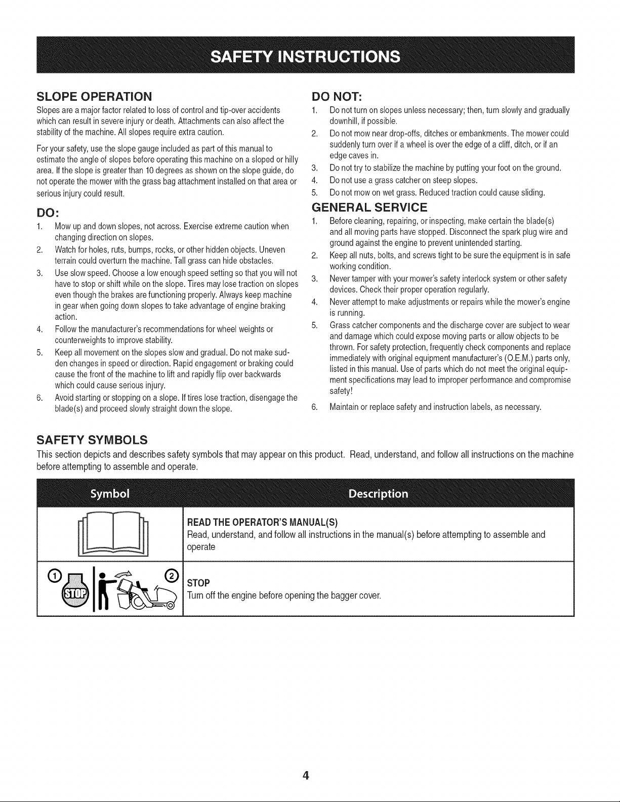
SAFETY SYMBOLS
This section depicts and describes safety symbols that may appear on this product. Read, understand, and follow all instructions on the machine
before attempting to assemble and operate.
I
I
READTHEOPERATOR'SMANUAL(S)
Read,understand,andfollowall instructionsinthe manual(s)beforeattemptingto assembleand
operate
STOP
Turnoffthe enginebeforeopeningthe baggercover.
4
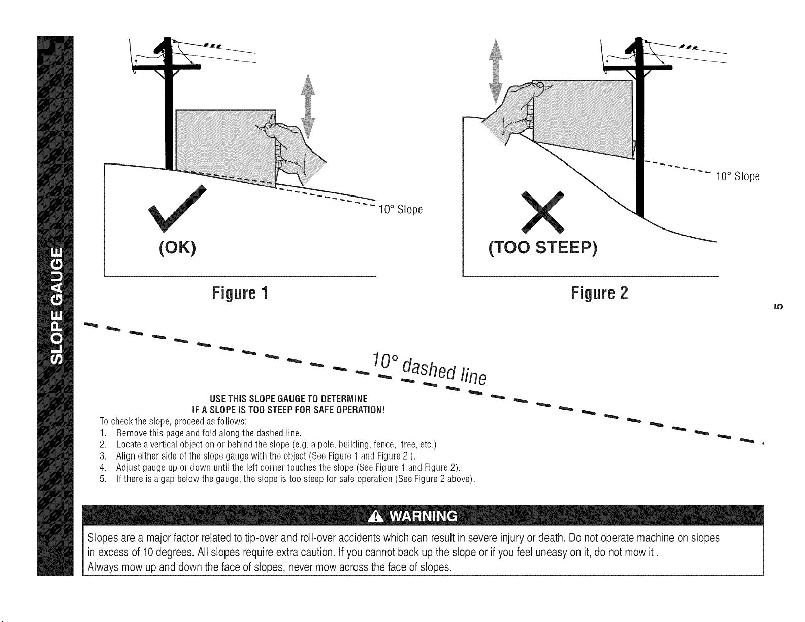
(OK)
10° Slope
(TOO STEEP)
10° Slope
Figure 1
USETHiSSLOPEGAUGETO DETERMINE
iFA SLOPEiS TOOSTEEPFORSAFEOPERATION!
Tocheckthe slope,proceedas follows:
1. Removethis pageandfold along the dashedline.
2. Locateavertical objecton or behindthe slope(e.g.a pole,building,fence, tree, etc.)
3. Aligneither sideof the slopegaugewith the object (SeeFigure1 andFigure2 ).
4. Adjustgaugeup or down until the left cornertouchesthe slope(SeeFigure1 andFigure2).
5.
10odashedline
If there is a gapbelowthe gauge,the slope is too steepfor safeoperation(SeeFigure2 above).
Figure2
Slopes are a majorfactor related to tip-over and roll-over accidents which can result in severe injury or death. Do not operate machineon slopes
in excess of 10degrees. All slopes requireextra caution, if you cannot back up the slope or if you feel uneasy on it, do not mow it.
Always mow up and down the face of slopes, nevermow across the face of slopes.
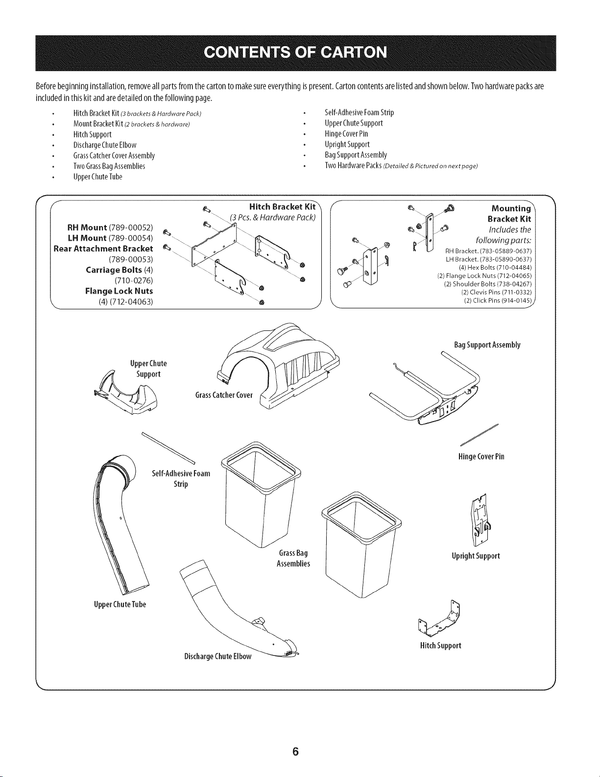
Beforebeginninginstallation,removeall partsfromthecartonto makesureeverythingispresent.Cartoncontentsarelistedandshownbelow.Twohardwarepacksare
includedin thiskit andaredetailedon the followingpage.
HitchBracketKit(3brackets & Hardware Pack)
MountBracketKit(2brackets & hardware)
HitchSupport
DischargeChuteElbow
GrassCatcherCoverAssembly
TwoGrassBagAssemblies
UpperChuteTube
Self-AdhesiveFoamStrip
UpperChuteSupport
HingeCoverPin
UprightSupport
BagSupportAssembly
TwoHardwarePacks(Detailed & Pictured on next page)
F
RH Mount (789-00052)
LH Mount (789-00054)
Rear Attachment Bracket
(789-00053)
Carriage Bolts (4)
(710-0276)
Flange Lock Nuts
'-- (4) (712-04063)
Hitch Bracket Kit-'_'
(3 Pcs. & Hardware Pack)
Mountin
Bracket Kit
e_.ljl _ Includes the
LH Bracket. (783-05890-0637)
(4) Hex Bolts (710-04484)
(2) Flange Lock Nuts (712-04065)
(2) Shoulder Bolts (738-04267)
(2) Clevis Pins (711-0332)
(2) Click Pins (914-0145) j
UpperChute
Support
UpperChuteTube
GrassCatcherCover
Self-AdhesiveFoam
Strip
BagSupportAssembly
@
DischargeChuteElbow
HingeCoverPin
UprightSupport
HitchSupport
6
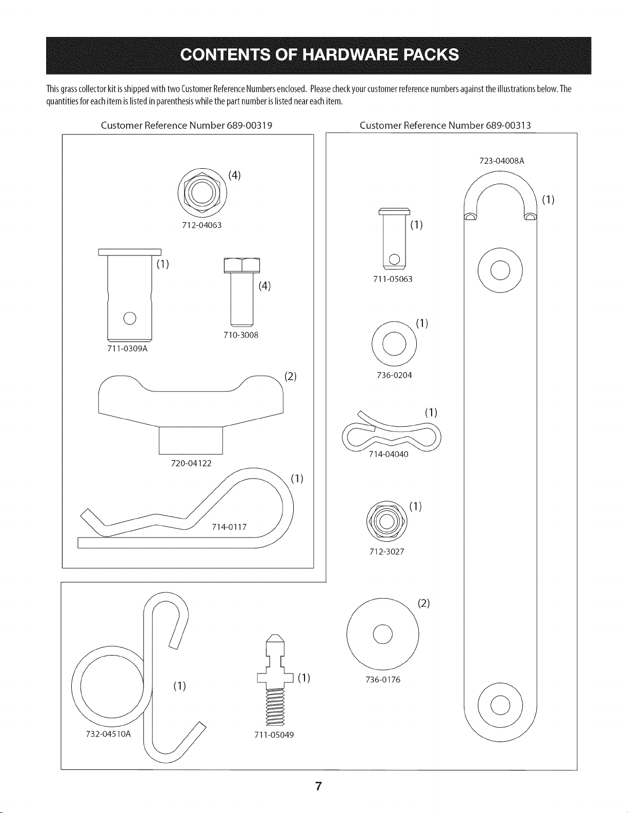
Thisgrasscollectorkit isshippedwith two CustomerReferenceNumbersenclosed.Pleasecheckyourcustomerreferencenumbersagainstthe illustrationsbelow.The
quantitiesforeachitem islistedin parenthesiswhilethepartnumberis listedneareachitem.
Customer Reference Number 689-00319 Customer Reference Number 689-00313
(4)
712-04063
©
711-0309A
t
(1)
4)
710-3008
720-04122
714-0117
(2)
1)
732-04510A
(1)
711-05049
(1)
711-05063
(1)
736-0204
(1)
714-04040
(1)
712-3027
2)
736-0176
723-04008A
(1)
7
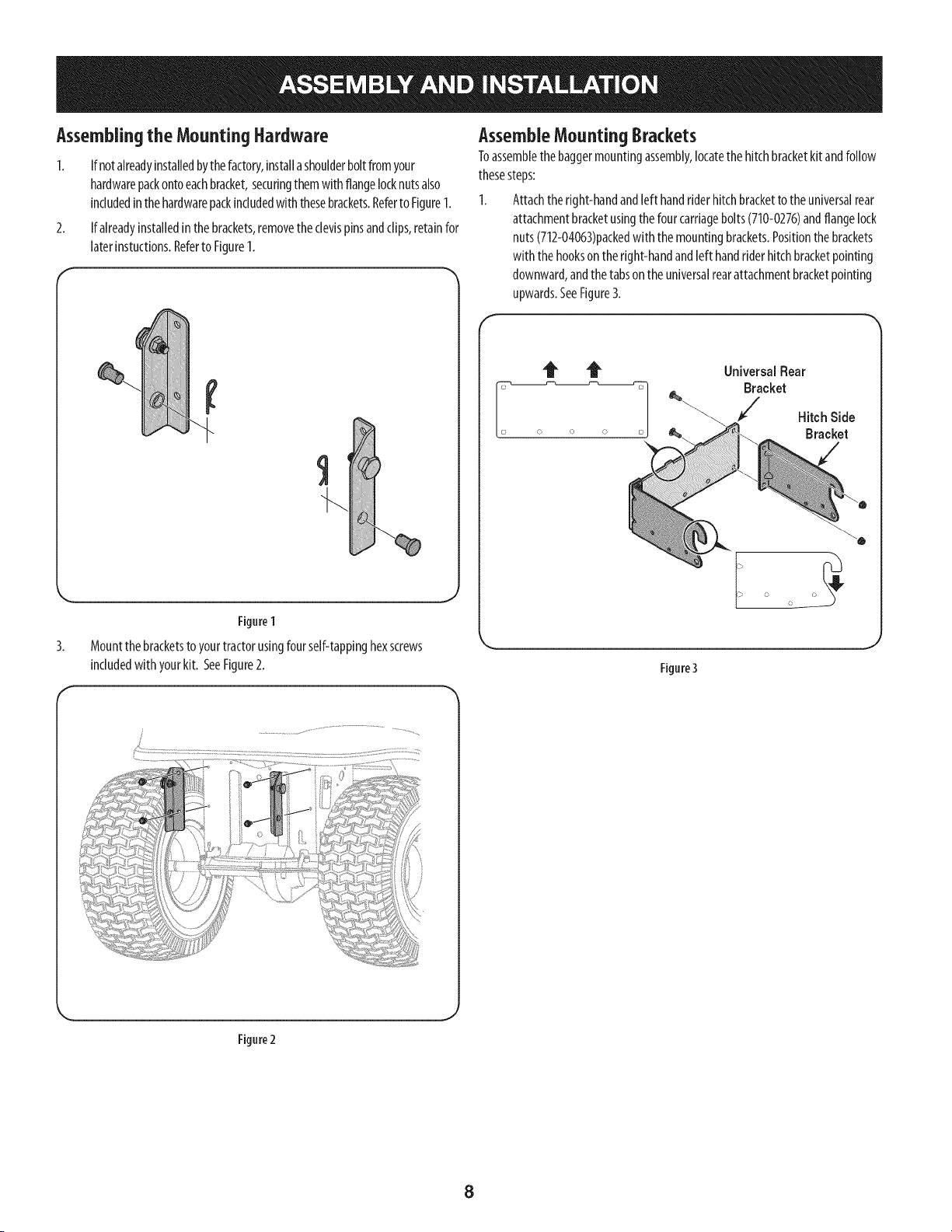
Assemblingthe MountingHardware
1. If notalreadyinstalledbythefactory,installashoulderboltfromyour
hardwarepackontoeachbracket,securingthemwith flangelocknutsalso
includedinthehardwarepackincludedwiththesebrackets.Referto Figure1.
2. If alreadyinstalledinthebrackets,removethe clevispinsandclips,retainfor
laterinstuctions.Referto Figure1.
Figure1
3. Mountthebracketsto yourtractorusingfourself-tappinghexscrews
includedwith yourkit. SeeFigure2.
AssembleMounting 8rackets
Toassemblethe baggermountingassembly,locatethe hitchbracketkit andfollow
thesesteps:
I. Attachthe right-handandleft handriderhitchbracketto the universalrear
attachmentbracketusingthe four carriagebolts(710-0276)andflangelock
nuts(712-04063)packedwith the mountingbrackets.Positionthebrackets
with the hookson the right-handandleft handriderhitchbracketpointing
downward,andthe tabson the universalrearattachmentbracketpointing
upwards.SeeFigure3.
UniversalRear
Bracket
Hitch Side
Bracket
Figure3
f
Figure2
8
2.
f
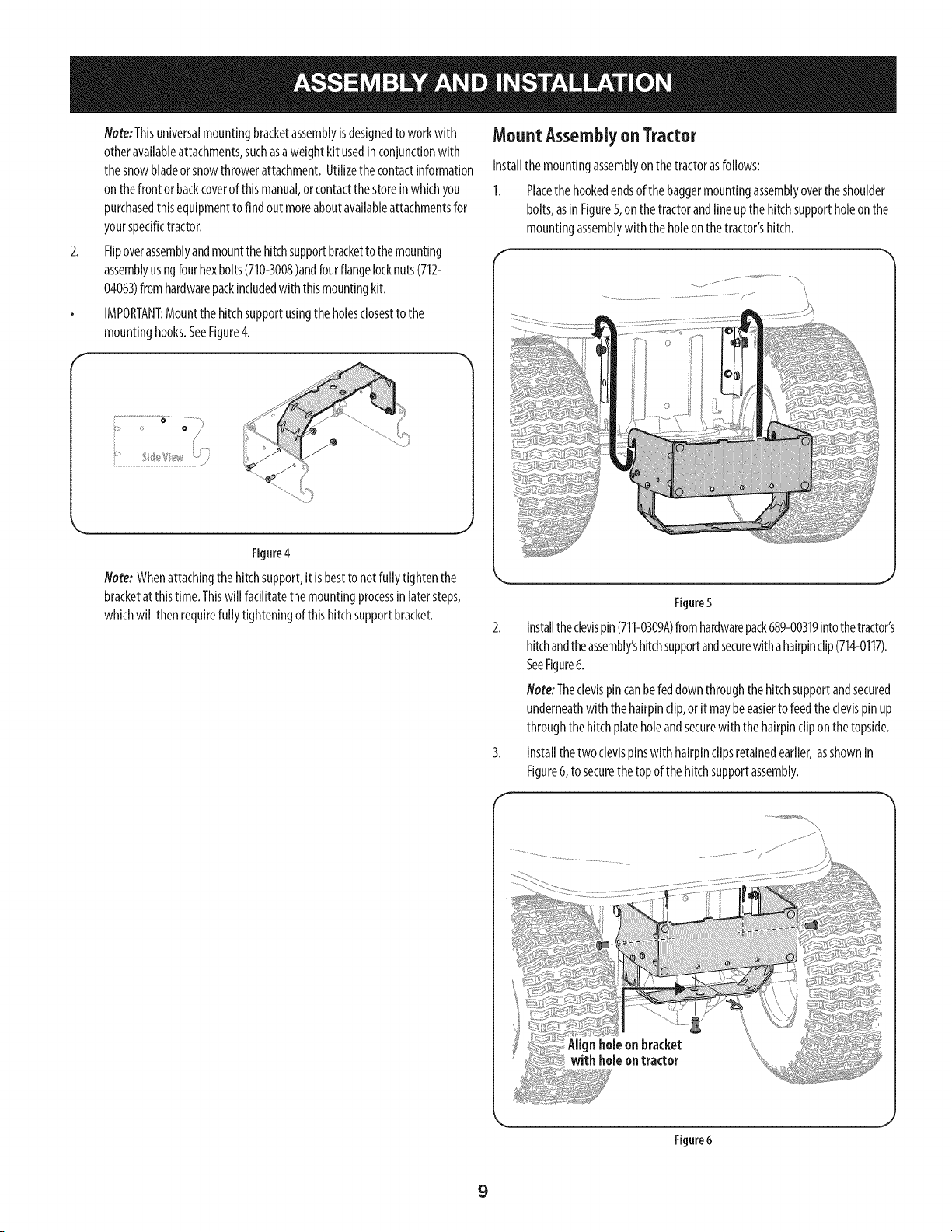
Note:Thisuniversalmountingbracketassemblyisdesignedto workwith
otheravailableattachments,suchasaweightkit usedin conjunctionwith
thesnowbladeor snowthrowerattachment.Utilizethecontactinformation
onthe front orbackcoverof thismanual,orcontactthestoreinwhichyou
purchasedthisequipmentto find out moreaboutavailableattachmentsfor
yourspecifictractor.
Flipoverassemblyandmountthehitchsupportbracketto themounting
assemblyusingfourhexbolts(710-3008)andfourflangelocknuts(712-
04063)fromhardwarepackincludedwith thismountingkit.
IMPORTANT:Mountthehitchsupportusingthe holesclosestto the
mountinghooks.SeeFigure4.
o o /
............... #
....}
Figure4
Note: Whenattachingthe hitchsupport,it is bestto notfullytighten the
bracketat thistime.Thiswill fadlitatethe mountingprocessinlatersteps,
whichwill thenrequirefullytighteningofthishitch supportbracket.
MountAssemblyon Tractor
Installthe mountingassemblyonthe tractorasfollows:
1. Placethehookedendsofthe baggermountingassemblyoverthe shoulder
bolts,asinFigure5,onthe tractorandlineupthehitchsupportholeonthe
mountingassemblywith theholeonthe tractor'shitch.
Figure5
Installthe clevispin(711-0309A)fromhardwarepack689-00319intothetractor's
hitchandtheassembly'shitchsupportandsecurewithahairpinclip(714-0117).
SeeFigure6.
Note:Theclevispincanbefed downthroughthehitchsupportandsecured
underneathwith thehairpinclip,orit maybeeasierto feedthe clevispinup
throughthehitchplateholeandsecurewith thehairpinclipon the topside.
Installthe two clevispinswith hairpinclipsretainedearlier,asshownin
Figure6, to securethe topof thehitchsupportassembly.
Figure6
J
9
4,
5.
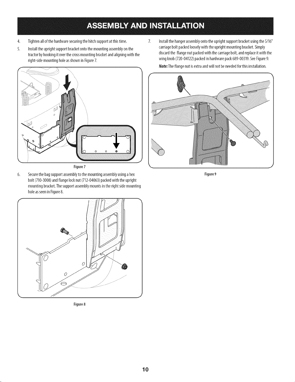
Tightenallof the hardwaresecuringthe hitchsupportat thistime.
Installthe uprightsupportbracketontothe mountingassemblyon the
tractorbyhookingit overthe crossmountingbracketandaligningwith the
right-sidemountingholeasshowninFigure7.
Figure7
6,
Securethebagsupportassemblytothe mountingassemblyusingahex
bolt (710-3008)andflangelocknut(712-04063)packedwith theupright
mountingbracket.Thesupportassemblymountsinthe rightsidemounting
holeasseenin Figure8.
Installthe hangerassemblyontothe uprightsupportbracketusingthe 5/16"
carriagebolt packedlooselywith theuprightmountingbracket.Simply
discardthe flangenut packedwith thecarriagebolt, andreplaceitwith the
wing knob(720-04122)packedin hardwarepack689-00319.SeeFigure9.
Note:Theflangenut isextraandwill notbeneededforthisinstallation.
Figure9
Figure8
10
AssemblingRemainingBaggerComponents
Nowthat themountingbracketsareassembledandareinplaceonthe tractor,
followthesestepsto assemblethe remainingbaggercomponents.
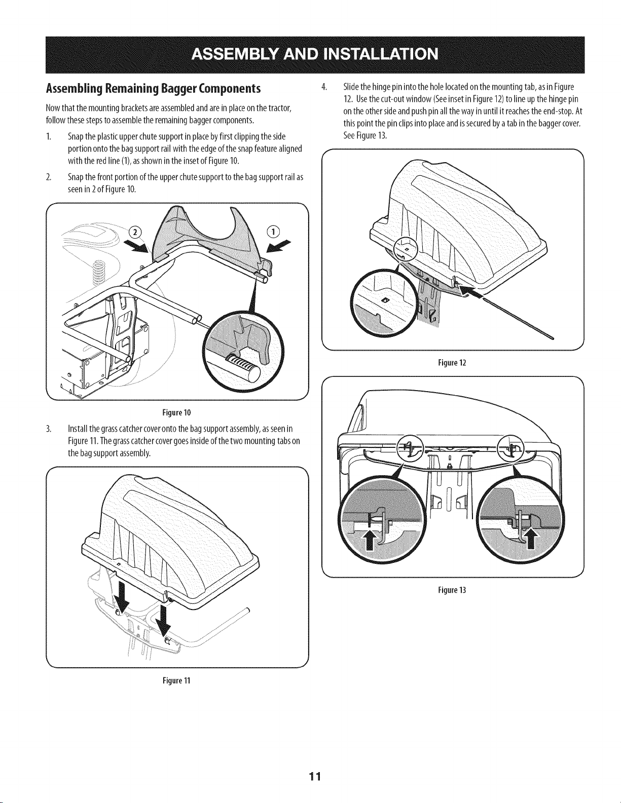
1. Snaptheplasticupperchutesupportin placebyfirst clippingthe side
portionontothe bagsupportrailwith theedgeofthesnapfeaturealigned
with the redline(1),asshownin the insetof Figure10.
2. Snapthefront portionof theupperchutesupporttothebagsupportrailas
seenin 2 of Figure10.
Slidethe hingepin intothe holelocatedonthe mountingtab,asinFigure
12.Usethecut-outwindow(Seeinsetin Figure12)to lineup the hingepin
on the othersideandpushpinall thewayin until it reachestheend-stop.At
this pointthe pin clipsinto placeandissecuredbyatab inthe baggercover.
SeeFigure13.
Figure12
3.
f
Figure 10
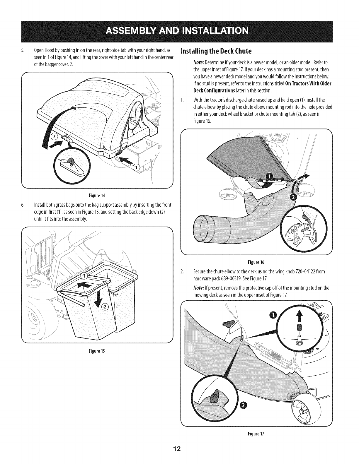
Installthegrasscatchercoverontothe bagsupportassembly,asseenin
Figure11.Thegrasscatchercovergoesinsideof thetwo mountingtabson
the bagsupportassembly.
Figure13
Figure 11
11
5.
6.
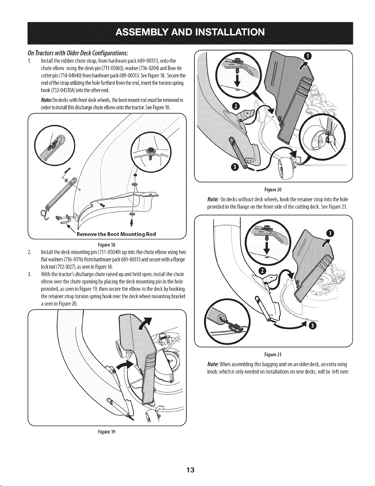
OpenHoodbypushinginontherear,right-sidetabwith yourrighthand,as
seenin1of Figure14,andliftingthecoverwith yourleft handinthecenterrear
ofthebaggercover,2.
Figure14
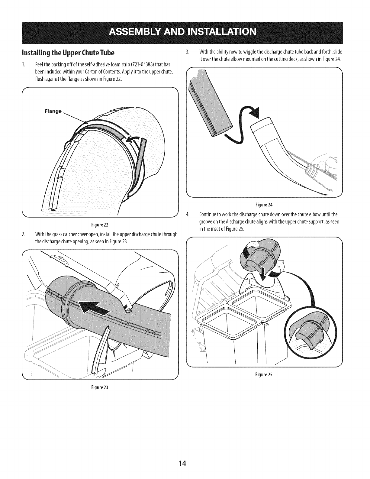
Installbothgrassbagsontothe bagsupportassemblybyinsertingthe front
edgeinfirst (1),asseenin Figure15,andsettingthe backedgedown(2)
until it fits intothe assembly.
Installingthe DeckChute
Note:Determineif yourdeckisa newermodel,or anoldermodel.Referto
the upperinsetof Figure17.Ifyourdeckhasamountingstudpresent,then
youhavea newerdeckmodelandyouwouldfollowthe instructionsbelow.
Ifno studispresent,referto theinstructionstitled OnTractorsWith Older
DeckConfigurations laterin thissection.
With thetractor'sdischargechuteraisedupandheldopen(1),installthe
chuteelbowbyplatingthechuteelbowmountingrodinto theholeprovided
ineitheryourdeckwheelbracketor chutemountingtab (2),asseenin
Figure16.
Figure15
Figure16
Securethechuteelbowto the deckusingthewing knob720-04122from
hardwarepack689-00319.SeeFigure17.
Note:If present,removethe protectivecapoffof the mountingstudon the
mowingdeckasseenintheupperinsetof Figure17.
Figure17
12
OnTractors with OlderOeckConfigurations:
1. Installthe rubberchutestrap,from hardwarepack689-00313,ontothe
chuteelbow usingthe clevispin(711-05063),washer(736-0204)andBow-tie
cotterpin(714-04040)fromhardwarepack689-00313.SeeFigure18.Securethe
endofthestraputilizingtheholefurthestfromthe end,insertthetorsionspring
hook(732-04510A)intotheotherend.
Note:Ondeckswithfrontdeckwheels,thebootmountrodmustberemovedin
ordertoinstallthisdischargechuteelbowontothetractor.SeeFigure18.
\
2.
3.
I
_ Remove the Boot Mounting Rod
Figure18
Installthedeckmountingpin(711-05049)upintothe chuteelbowusingtwo
flatwashers(736-0176)fromhardwarepack689-00313andsecurewithaflange
locknut(712-3027),asseeninFigure18.
With thetractor'sdischargechuteraisedupandheldopen,installthechute
elbowoverthe chuteopeningbyplacingthedeckmountingpinin the hole
provided,asseeninFigure19,thensecuretheelbowto thedeckbyhooking
theretainerstraptorsionspringhookoverthedeckwheelmountingbracket
aseenin Figure20.
Figure20
Note: Ondeckswithout deckwheels,hooktheretainerstrapinto the hole
providedintheflangeon the front-sideofthe cuttingdeck.SeeFigure21.
\
Figure21
Note:Whenassemblingthisbaggingunit on anolderdeck,an extrawing
knob,whichisonlyneededoninstallationsonnewdecks,will be left over.
Figure 19
13
Installingthe UpperChuteTube
Peelthe backingoff ofthe self-adhesivefoamstrip(721-04388)that has
beenincludedwithin yourCartonof Contents.Applyit to theupperchute,
flushagainsttheflangeasshownin Figure22.
With theabilitynowto wigglethedischargechutetubebackandforth,slide
it overthe chuteelbowmountedonthe cuttingdeck,asshownin Figure24.
Figure22
Withthegrasscatchercoveropen,installthe upperdischargechutethrough
thedischargechuteopening,asseeninFigure23.
Figure23
Figure24
Continuetowork thedischargechutedownoverthechuteelbowuntil the
grooveon thedischargechutealignswith the upperchutesupport,asseen
intheinsetof Figure25.
Figure25
14
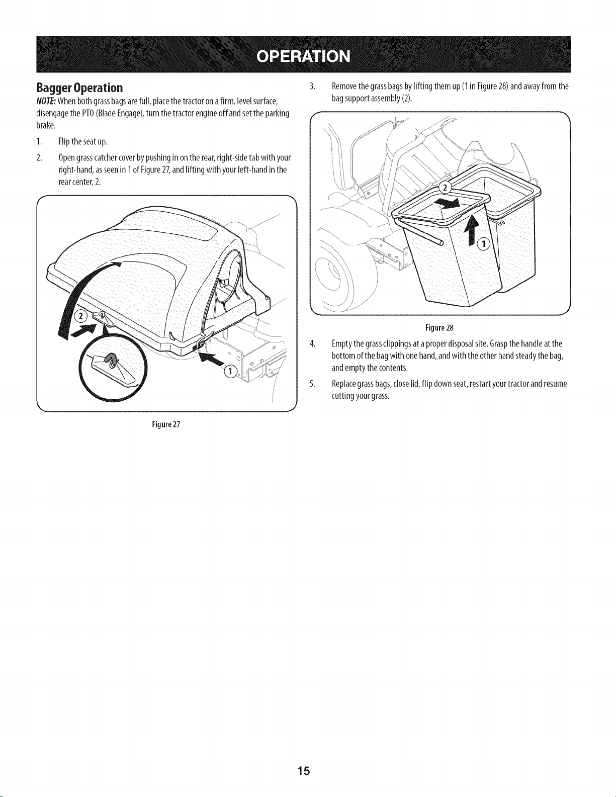
Bagger Operation
NOTE:Whenbothgrassbagsarefull, placethe tractoronafirm, levelsurface,
disengagethe PTO(BladeEngage),turn thetractorengineoffandsetthe parking
brake.
1,
2.
Fliptheseatup.
Opengrasscatchercoverbypushingin ontherear,right-sidetab with your
right-hand,asseenin 1of Figure27,andlifting with yourleft-handinthe
rearcenter,2.
Removethe grassbagsbylifting themup (1 inFigure28)andawayfromthe
bagsupportassembly(2).
Figure 27
Figure28
4. Emptythegrassclippingsat aproperdisposalsite.Graspthehandleat the
bottomof thebagwith onehand,andwiththe otherhandsteadythebag,
andemptythe contents.
5. Replacegrassbags,closelid,flip downseat,restartyourtractorandresume
cuttingyourgrass.
15
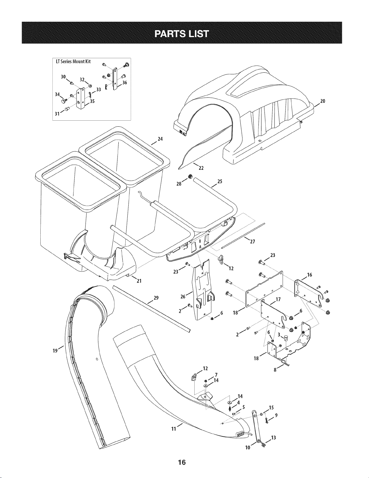
LT_eriesMountKit i
34\ _1 I_
2O
29
J
12
_27
23
10
16

CRAFTSMANTWOBINBAGGERModelNo.247.240192
Topurchasereplacement parts, call 1-800-469-4663
I
Ref, I Part Number
1. 689-00101
2. 710-3008
3. 711-0309A
4. 711-05049
5. 711-05063
6. 712-04063
7. 712-3027
8. 714-0117
9. 714-04040
I0. 723-04008A
II. 631-05029
12. 720-04122
13. 732-04510A
14. 736-0176
15. 736-0204
16. N/A*
17. N/A*
18. 783-05887-0637
19. 931-04295A
20. 931-04292
21. 731-06497
22. 731-06504
23. 710-0276
24. 964-04090A
25. 683-04461-0637
26. 683-04519-0637
27. 711-04988
28. 735-0246A
29. 721-04388
30. 710-04484
31. 711-0332
32. 712-04065
33. 914-0145
34. 738-04267
35 783-05889A-0637
36. 783-05890A-0637
Description
Mounting Bracket Kit (Incl. ref. 16, 17,18)
Hex Head Screw, 5/16-18 x .75"
Clevis Pin, .62" Dia.
Attachment Pin, 1/4 x 0.66 Lg.
Clevis Pin, 5/16 x .75 Lg.
Flange Lock Nut, 5/16-18
Flange Lock Nut, 1/4-20
Internal Cotter Pin, .148 x 3.00
Bow-Tie Cotter Pin, 72
Chute Strap, 6.00 Lg.
Bagger Discharge Chute, Elbow
Wing Knob, 5/16-18
Torsion Spring Hook
Flat Washer, .265 x .938 x .120
Flat Washer, .344 x .62 x .033
Mounting Bracket, LH
Mounting Bracket, RH
Universal Bracket Support
Upper Discharge Chute
Double Bagger Cover Assembly
Upper Chute Support
Bagger Cover Screen
Carriage Screw, 5/16-18 x 1.00"
Grass-bag Assembly
Double Bag Support Assembly
Vertical Support Bracket
Cover Hinge Pin
End Plug
Self-Adhesive Foam Strip
Tap Screw, 5/16-18 x .750
Clevis Pin
Flange Lock Nut, 3/8-16
Click Pin, .092 x 1.64 Lg.
Shoulder Screw, .625 x .412
Mounting Bracket, RH
Mounting Bracket, LH
*Order Reference 1
17

Sinstrucciones De Seguridad ............................................... 19-21
Contenido de la Caja ............................................................. 22-23
Montaje e Instalaci6n ........................................................... 24-30
Operaci6n ................................................................................... 31
Lista de piezas ...................................................................... 16-17
GARANTiACOMPLETADE UN ANO DE ARTESANO
DURANTEunaSodesde lafecha de compra,esteproductoestAgarantizadocontracualquierdefectode materialo manode obra.Un producto
defectuososer_reemplazadosin cargo.
Paraquedetallesde lacoberturadegarantiaobtenerun reemplazolibre,visiteel sitioweb:www.craftsman.com
EstagarantiaserAnula si esteproductose utilizamientrasqueproporcionaservicioscomercialeso Sialquilaa otra persona.
Estagarantiale otorgaderechoslegalesespecificos,y ustedtambi_npuedetenerotrosderechosquevariandeestadoa estado.
Sears Brands ManagementCorporation., Hoffman Estates, IL 60179
© SEARSBRANDS,LLC 18
Lapresenciadeeste sirnboloindicaque setratade instrucciones
irnportantesde seguridadquese debenrespetarpara evitar
ponerenpeligrosu seguridadpersonaly/o materialy la de otras
personas.Lea y siga todaslas instruccionesde este manualantes
de poneren funcionarnientoestarnAquina.Si no respetaestas
instruccionespodriaprovocarlesionespersonales.Cuandoveaeste
sirnbolo,ipresteatenci6na la advertencia!
PROPOSICION 65 DE CALIFORNIA
Elescapedel motordeesteproducto,algunosde suscornponentes
y algunoscornponentesdelvehiculocontieneno liberan sustancias
quirnicasqueelestadodeCaliforniaconsideraque puedenproducir
cancer,defectosde nacirnientou otros problernasreproductivos.
Losbornesde la bateriay los accesoriosalinescontienenplornoy
cornpuestosde plorno,sustanciasquirnicasque seg_nIo estableci-
do porel Estadode Californiacausancancery daSosen el sisterna
reproductivo.Ldveselas manos despu_sde estar en contacto
con estoscomponentes.
EstarnAquinarueconstruidapara seroperadadeacuerdocon
las reglasde seguridadcontenidasen este manual.AI igualque
concualquiertipo deequipornotorizado,undescuidoo error por
partedeloperadorpuedeproducirlesionesgraves.Esta rnAquina
es capazde arnputarrnanosy piesy de arrojarobjetoscon gran
fuerza.Deno respetarlas instruccionesde seguridadsiguientesse
puedenproducirlesionesgraveso la rnuerte.
Su responsabilidad--Restrinja el usode esta rnAquina
rnotorizadaalas personasque lean,cornprendany respetenlas
advertenciase instruccionesque aparecenen estemanualyen la
rnAquina.
iGUARDEESTASINSTRUCCIONES!
Fundonamiento general
1. Lea, comprenda y respete todas las instrucciones que figuran
en el equipo yen los manuales antes de intentar armarlo y
hacerlo funcionar. Guarde este manual en un lugar seguro
para consultas futuras y peri6dicas, asi como para solicitar
repuestos.
2. Para ayudar a evitar una lesi6n pot contacto con las cuchillas
o con un objeto que sea arrojado, mantenga alas personas
que observan, a los ayudantes, ni_os y mascotas alejados a no
menos de 25 metros de la m_quina mientras est& funcionando.
Detenga la m&quina si alguien entra en la zona.
3. Revise minuciosamente el _irea donde se va a usar el equipo.
Retire todas las piedras, palos, cables, huesos, juguetes y otros
objetos extra_os que podrian set recogidos y arrojados por la
acci6n de las cuchillas. Los objetos arrojados por la m&quina
pueden causar lesiones graves.
4. Para protegerse los ojos, utilice siempre galas o lentes de
seguridad mientras opera la m&quina o mientras la ajusta
o repara. Los objetos arrojados que rebotan pueden causar
lesiones oculares graves.
5. Nunca opere la cortadora de c_sped sin tenet bien colocada
la cubierta de descarga o el colector de c6sped. Si falta o
est_ da_ada la cubierta de descarga oun componente del
accesorio embolsador puede resultar en lesiones por contacto
con la cuchilla o con objetos arrojados.
6. No ponga las manos ni los pies cerca de las piezas rotatorias ni
debajo de la plataforma de corte. El contacto con las cuchillas
puede resultar en la amputaci6n de una mano o pie.
7. Apague el motor de la cortadora de c_sped y espere que
las cuchillas se detengan totalmente antes de desbloquear
la abertura de descarga de la cortadora o las piezas de la
embolsadora.
8. Reduzca la velocidad antes de girar. Opere la m&quina de
forma pareja. Evite el funcionamiento err_itico y la velocidad
excesiva. Tenga en cuenta que el accesorio colector de c6sped
puede afectar las caracteristicas de manejo de su cortadora.
Fundonamiente en pendientes
Las pendientes son un factor importante en los accidentes
ocasionados pot p_rdida de control y vuelcos que pueden causar
lesiones graves e incluso la muerte. Los accesorios tambien pueden
afectar la estabilidad de la m&quina. La operaci6n en pendiente
requiere mayor precauci6n.
Para seguridad, use el medidor de pendientes que se incluye como
parte de este manual para estimar el _ingulo de la pendiente antes
de hacer funcionar la m_iquina en una zona inclinada. Si la pendiente
es mayor a 10 grados en el medidor, no opere la cortadora con el
accesorio embolsador en ese sector, pues podria causar lesiones
graves.
HagaIo siguiente:
1. Corte hacia arriba y abajo de las pendientes, no en forma
transversal. Tenga sumo cuidado al cambiar de direcci6n en
una pendiente.
2. Est_ atento a los hoyos, surcos, baches, rocas, u otros objetos
ocultos. El terreno desnivelado puede voltear la m&quina. El
pasto alto puede ocultar obst_iculos.
3. Conduzca a baja velocidad. Elija una velocidad Io
suficientemente baja como para no tener que detenerse
o cambiar de marcha mientras est,1 en la pendiente. Los
neum_ticos pueden perder tracci6n en las pendientes aun
cuando los frenos funcionen correctamente. Mantenga
la m&quina siempre en velocidad cuando desciende una
pendiente, para poder frenar con el motor.
19
4. Siga las recomendaciones del fabricante sobre pesos y
contrapesos de las ruedas, para mejorar la estabilidad.
5. Haga que todos los movimientos en las pendientes sean
lentos y graduales. No cambie repentinamente la velocidad
ni la direcci6n. Un frenado o cambio de velocidad repentinos
pueden causar que el frente de la m_quina se levante y d6 una
voltereta hacia atr_s, Io que podria causar lesiones graves.
6. Evite arrancar o detenerse en una pendiente. Silos neum_ticos
pierden tracci6n, desenganche las cuchillas y descienda
lentamente la pendiente.
No haga I0siguiente:
I. No gire en una pendiente a menos que sea imprescindible. De
ser posible, gire lenta y gradualmente cuesta abajo.
2. No corte el c_sped cerca de barrancos, zanjas o terraplenes. La
cortadora de c_sped podria volcarse repentinamente si una de
las ruedas estuviera sobre el borde de un acantilado o zanja, o
si un borde se desmoronara.
3. No intente estabilizar la m_quina poniendo el pie en el suelo.
4. No utilice un colector de c_sped en pendientes empinadas.
5. No corte el c_sped humedo. Una reducci6n en tracci6n puede
causar derrapes.
Servid0 general
I. Antes de limpiar, reparar o inspeccionar la m_quina,
compruebe que las cuchillas y todas las piezas m6viles se
hayan detenido. Desconecte el cable de la bujia y p6ngalo
haciendo masa contra el motor para evitar que arranque
accidentalmente.
2. Mantenga todas las tuercas, pernos y tornillos bien ajustados
para asegurarse de que el equipo est_ en condiciones seguras
de operaci6n.
3. Nunca intente violar el sistema de bloqueo de seguridad u
otros mecanismos de seguridad de la cortadora. Controle
peri6dicamente que funcionan correctamente.
4. No intente nunca hacer ajustes o reparaciones a la cortadora
mientras el motor est_ en marcha.
5. Los componentes del colector de c6sped y la cubierta de
descarga est_n sujetos a desgaste y daffos que podrian dejar
expuestas piezas que se mueven o permitir que se arrojen
objetos. Para proteger su seguridad, verifique frecuentemente
todos los componentes y reempl_celos inmediatamente
0nicamente con piezas de los fabricantes del equipo original
(O.E.M.) indicados en este manual. El uso de piezas que no
cumplen con las especificaciones del equipo original puede
resultar en rendimiento inadecuado y puede poner en peligro
la seguridad.
6. Mantenga o reemplace las etiquetas de seguridad y de
instrucciones seg0n sea necesario.
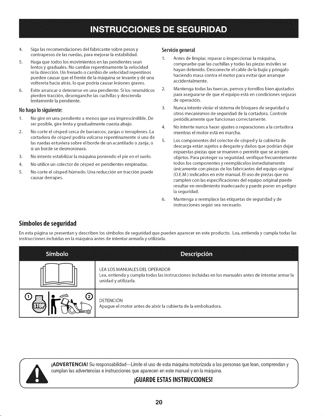
Simbolosde seguridad
En esta p_gina se presentan y describen los simbolos de seguridad que pueden aparecer en este producto. Lea, entienda y cumpla todas las
instrucciones incluidas en la m_quina antes de intentar armarla y utilizarla.
LEA LOS MANUALES DEL OPERADOR
Lea, entienda y cumpla todas las instrucciones incluidas en los manuales antes de intentar armar la
unidad y utilizarla.
DETENCION
Apague el motor antes de abrir la cubierta de la embolsadora.
iADVERTENCIA! Su responsabilidad--Limiteel usodeesta m_.quinamotorizadaalas personasque lean,comprendany
cumplanlasadvertenciase instruccionesqueapareceneneste manualyen la m_.quina.
iGLIARDEESTASINSTRL!CCIONES!
2O
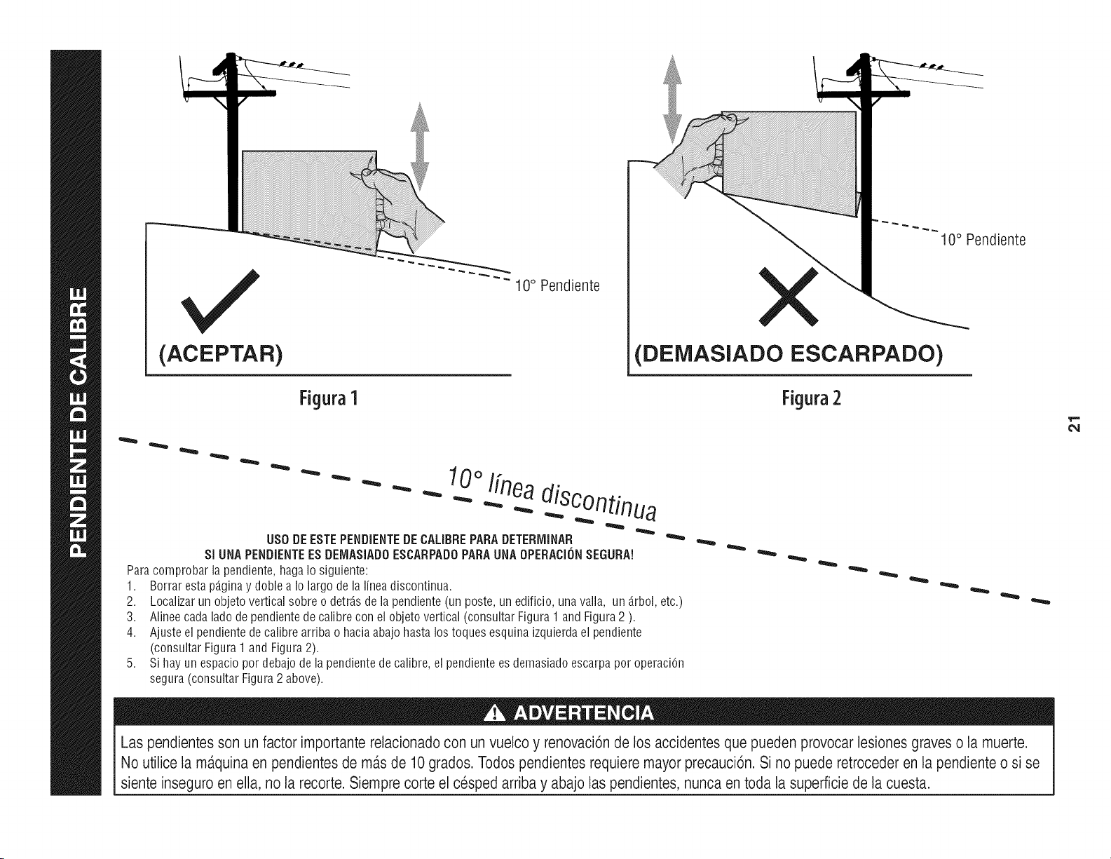
(ACEPTAR)
Figura1
"" 10 ° Pendiente
10° Pendiente
(DEiVIASlADO ESCARPADO)
Figura2
0oI[nea
- - " "" - _ .-...diSC°ntinua
US0 DEESTEPENDIENTEDECALIBREPARADETERiVIINAR
SI UNAPENDiENTEESDEIV1ASiADOESCARPADOPARAUNAOPERACi(_NSEGURA!
Paracomprobarlapendiente,hagaIosiguiente:
1. Borrarestap_.ginay doblea Io largodelalineadiscontinua.
2.
3.
4.
Localizarun objetoverticalsobreo detrJ.sde la pendiente(un poste,un edificio,unavalla, un _.rbol,etc.)
Alineecadalado de pendientedecalibrecon elobjetovertical(consultarFigura1 andFigura2 ).
Ajusteel pendientede calibrearriba o haciaabajo hastalos toquesesquinaizquierdael pendiente
(consultarFigura1andFigura2).
Sihayun espaciopordebajodela pendientedecalibre,el pendientees demasiadoescarpapor operaciOn
segura(consultarFigura2 above).
Las pendientesson un factor importante relacionadocon un vuelco y renovaci6n de los accidentesque pueden provocar lesiones graves o la muerte.
No utilice la m_.quinaen pendientes de m_.sde 10grados. Todos pendientesrequiere mayor precauci6n. Si no puede retrocederen la pendiente o si se
siente inseguro en ella, no la recorte. Siempre corte el cesped arriba y abajo laspendientes, nunca en toda la superficie de la cuesta.
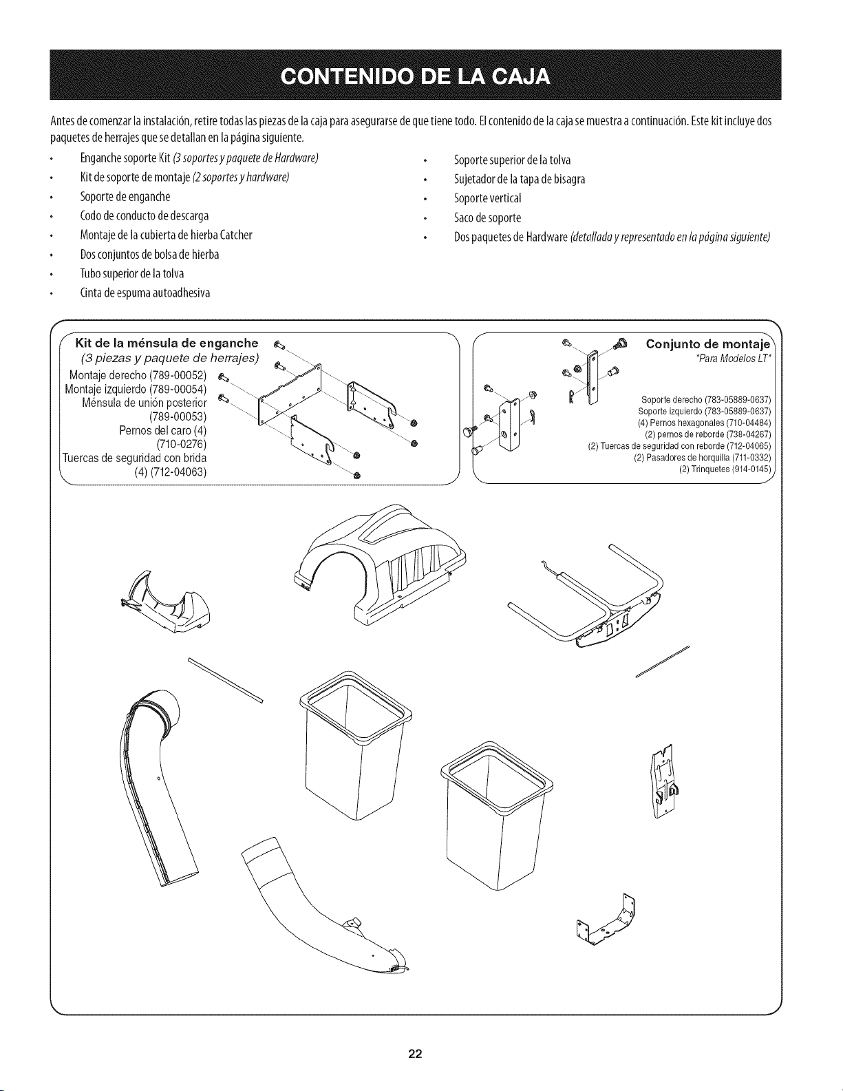
Antesde comenzarlainstalad6n,retiretodaslaspiezasdelacajaparaasegurarsedequetienetodo.Elcontenidodelacajasemuestraacontinuad6n.Estekit incluyedos
paquetesde herrajesquesedetallanenlap_iginasiguiente.
EnganchesoporteKit(3soportesy paquetedeHardware)
Kitdesoportedemontaje(2soportesyhardware)
Soportedeenganche
Cododeconductodedescarga
Montajede la cubiertadehierbaCatcher
Dosconjuntosde bolsadehierba
Tubosuperiordelatolva
Cintadeespumaautoadhesiva
Soportesuperiorde latolva
Sujetadordela tapadebisagra
Soportevertical
Sacodesoporte
Dospaquetes de Hardware(detalladay representadoen lap@inasiguiente)
f Kit de [a m_nsuia de enganche
(3 piezas y paquete de herrajes)
Montajederecho(789-00052)
Montajeizquierdo(789-00054)
Mensuladeuni6n posterior
(789-00053)
Pernosdel caro (4)
(710-0276)
Tuercasde seguridadcon brida
X (4) (712-04063) \
A
%
¢_.... _4_ Conjunto de montaje_
_ *ParaModelosLT*
_,/I_ Soporte derecho (783-05889-0637)
Soporte izquierdo(783-05889-0637)
(4) Pernos hexagonales (710-04484)
(2) pernos de reborde (738-04267)
(2)Tuercas de seguridad con reborde (712-04065)
(2) Pasadores de horquilla (711-0332)
(2) Trinquetes(914-014_
J
22
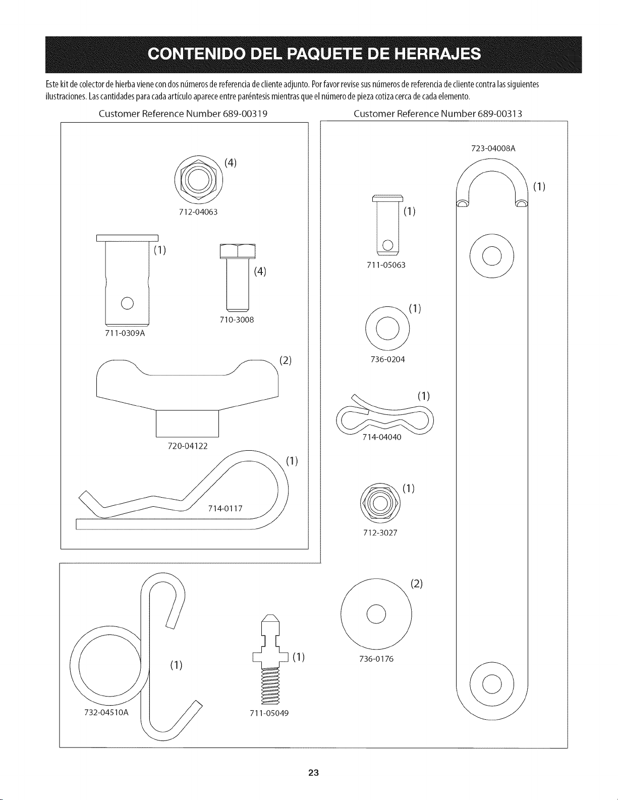
Estekit decolectorde hierbavienecondosnt_merosde referendadediente adjunto.Porfavorrevisesusnt_merosde referendadeclientecontralassiguientes
Hustradones.Lascantidadesparacadaartkulo apareceentrepar_ntesismientrasqueelnumerode piezacotizacercadecadaelemento.
Customer Reference Number 689-00319 Customer Reference Number 689-00313
(4)
712-04063
I
©
711-0309A
I
(1)
4)
710-3008
l
._(2)
720-04122
714-0117
1)
732-04510A
(1)
711-05049
(1)
(1)
711-05063
736-0204
(1)
714-04040
(1)
712-3027
2)
736-0176
723-04008A
(1)
23
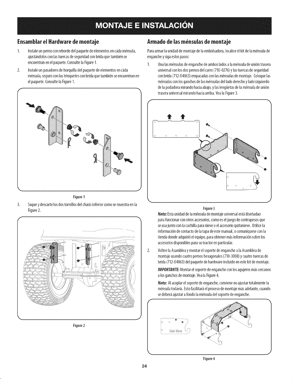
Ensamblarel Hardwaredemontaje
1. Instaleunpernoconrebordedelpaquetedeelementosenc_dam(_nsula,
ajust_ndolosconlastuercasdeseguridadconbridaquetambi(_nse
encuentranenelpaquete.ConsultelaFigure1.
2. Instaleunpasadoresdehorquilladelpaquetedeelementosenc_da
m_nsula,seguroconlastrinquetesconbridaquetambi_nseencuentranen
elpaquete.ConsultelaFigure1.
Figure1
3. Saquey descartelosdostorniiiosdelchasisinferiorcomosemuestraenla
Figure2.
Armadodeiasm nsuias de rnontaje
Paraarmarla unidadde montajedelaembolsadora,Iocaliceelkit de lam_nsulade
enganchey sigaestospasos:
1. Unalasm_nsulasdeenganchedeambosladosa lam(_nsuladeuni6ntrasera
universalconlosdospernosdelcarro(710-0276)y lastuercasde seguridad
conbrida(712-04063)empacadasconlasm_nsulasde montaje.Coloquelas
m(_nsuiasconlosganchosde lasm_nsulasdel ladoderechoyladoizquierdo
de lapodadoramirandohaciaabajo,y laslengiJetasde la m_nsulade uni6n
traserauniversalmirandohaciaarriba.VealaFigure3.
Figure3
Nora: Estaunidaddelam_nsulade montajeuniversalest_diseffadao
parafuncionarconotrosaccesorios,comoeseljuegode contrapesosque
seusajunto conlacuchillaparanieveoel accesorioquitanieve.Utilicela
informaci6nde contactodelatapadeestemanual,ocomun[queseconla
tiendadondeadquiri6elequipo,paraobtenerm_sinformaci6nsobrelos
accesoriosdisponiblesparasutractoren particular.
VolteelaAsambleay montarel soportedeenganchealaAsambleade
montajeusandocuatropernoshexagonales(710-3008)y cuatrotuercasde
brida(712-04063)delpaquetede hardwareinduidoenestekit de montaje.
IMPOR@NTE:Montarel soportede engancheconlosagujerosm_scercanos
a losganchosdemontaje.VealaFigure4.
Nora: AIacoplarelsoportedeenganche,convieneno ajustartotalmentela
m_nsuiatodav[a.Estofacilitar_el procesodemontajem_sadelante,cuando
sedeber_ajustarafondolam_nsuladelsoportedeenganche.
Figure2
o .............'
o /
/
Figure4
24
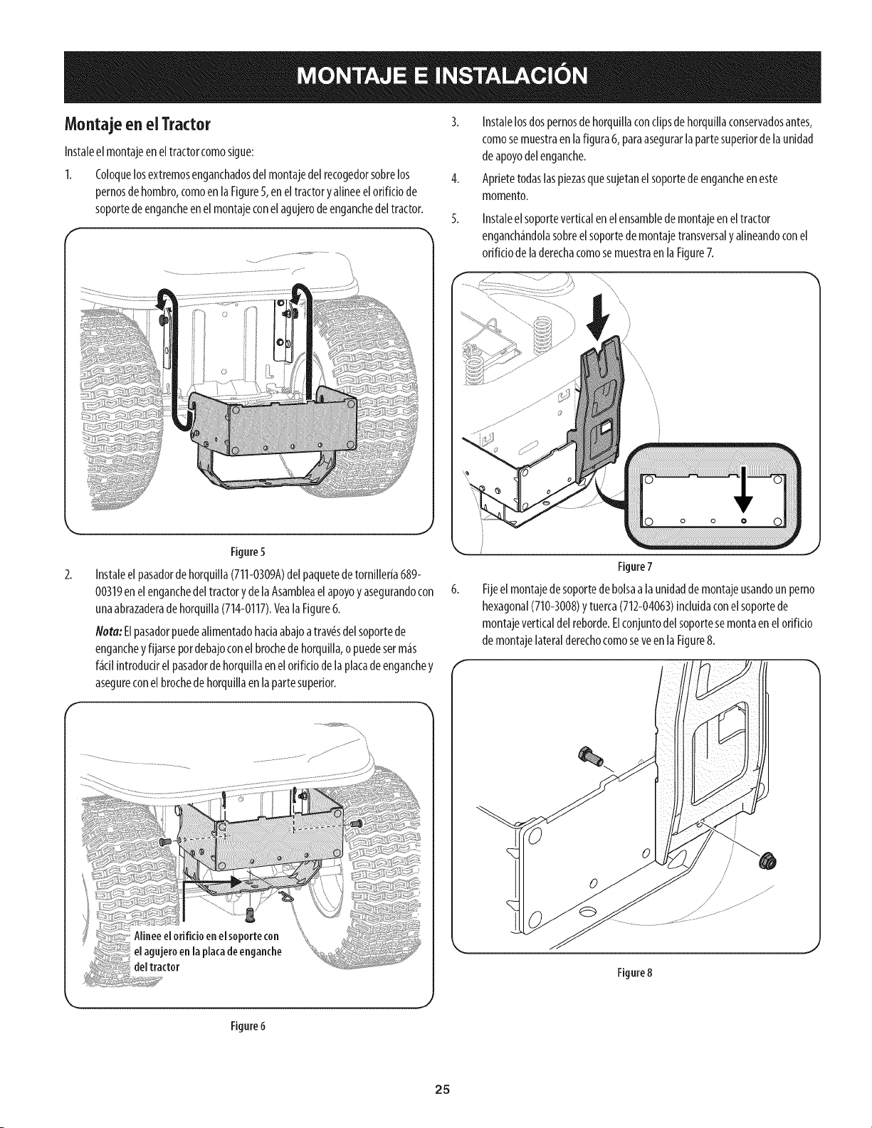
Montaje en el Tractor
Instaleel montajeeneltractorcomosigue:
I. Coloquelosextremosenganchadosdelmontajedelrecogedorsobrelos
pernosdehombro,comoen laFigure5,eneltractoryalineeelorificio de
soportedeengancheenel montajeconelagujerodeenganchedeltractor.
F
.........................................................................................../- .......
Figure5
2.
Instaleel pasadordehorquilla(711-0309A)delpaquetedetornilleria689-
00319enel enganchedeltractory delaAsambleael apoyoy asegurandocon
unaabrazaderade horquilla(714-0117).VealaFigure6.
Nora:Elpasadorpuedealimentadohaciaabajoatrav(gdel soportede
enganchey fijarsepordebajoconelbrochedehorquilla,o puedeserm_s
f_cilintrodudrel pasadordehorquillaenelorifido dela placade enganchey
asegureconel brochede horquillaen la partesuperior.
3. Instalelosdospernosde horquillaconclipsdehorquillaconservadosantes,
comosemuestraen lafigura6, paraasegurarlapartesuperiordela unidad
de apoyodelenganche.
4. Aprietetodaslaspiezasquesujetanel soportede engancheen este
momento.
Instaleelsoporteverticalenelensambledemontajeenel tractor
enganch_ndolasobreelsoportedemontajetransversaly alineandoconel
orificiode laderechacomosemuestraen laFigure7.
f s" .............................::'_ ..............
\
}
Figure7
Fijeelmontajede soportedebolsaa launidaddemontajeusandoun perno
hexagonal(710-3008)y tuerca(712-04063)incluidaconelsoportede
montajeverticaldel reborde.Elconjuntodelsoportesemontaenelorificio
de montajelateralderechocomoseveenlaFigure8.
Figure8
Figure6
25
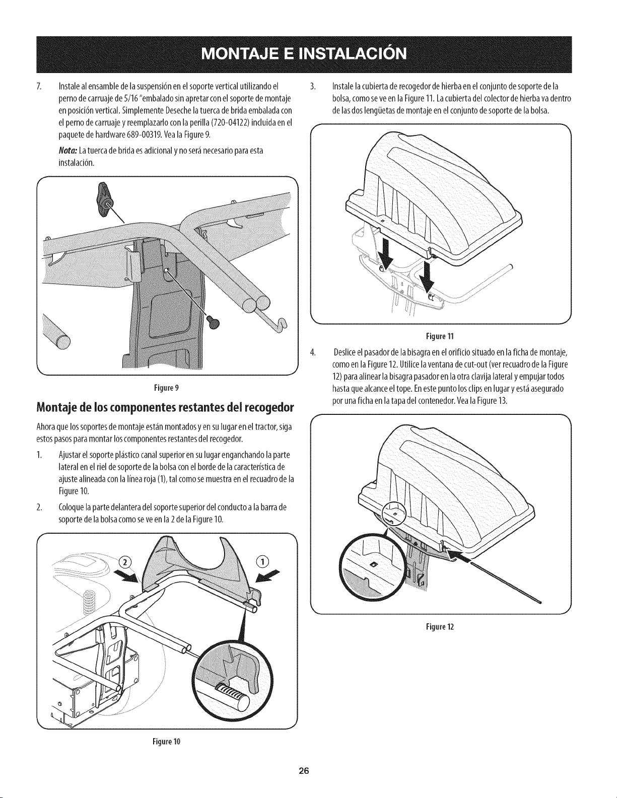
Instalealensambledelasuspensibnenelsoporteverticalutilizandoel
pernodecarruajede5/16"embaladosinapretarconelsoportedemontaje
enposici6nvertical.SimplementeDesechelatuercadebridaembaladacon
elpernodecarruajeyreemplazarloconlaperilla(720-04122)induidaenel
paquetedehardware689-00319.VealaFigure9.
Nora:Latuercadebridaesadicionaly noser_necesarioparaesta
instalacibn.
Figure9
Montaje de los ¢omponentes restantes del recogedor
Ahoraquelossoportesdemontajeest_nmontadosyen sulugaren eltractor,siga
estospasosparamontarloscomponentesrestantesdelrecogedor.
1. Ajustarel soportepl_sticocanalsuperiorensulugarenganchandola parte
lateralen elrieldesoportedela bolsaconelbordedelacaracteristicade
ajustealineadaconlalinearoja(1),tal comosemuestraenel recuadrode la
Figure10.
2. Coloquelapartedelanteradelsoportesuperiordel conductoala barrade
soportede labolsacomoseveenla 2de la Figure10.
Instalelacubiertade recogedorde hierbaenelconjuntodesoportedela
bolsa,comoseveen laFigure11.Lacubiertadel colectorde hierbavadentro
de lasdosleng_Jetasdemontajeenelconjuntodesoportedelabolsa.
Figure11
Desliceelpasadorde labisagraen elorifido situadoen lafichade montaje,
comoenla Figure12.Utilicela ventanadecut-out(verrecuadrode la Figure
12)paraalinearlabisagrapasadorenlaotraclavijalateraly empujartodos
hastaquealcanceel tope.Enestepuntolosclipsenlugary est_asegurado
porunafichaen latapadelcontenedor.Veala Figure13.
Figure12
Figure10
26
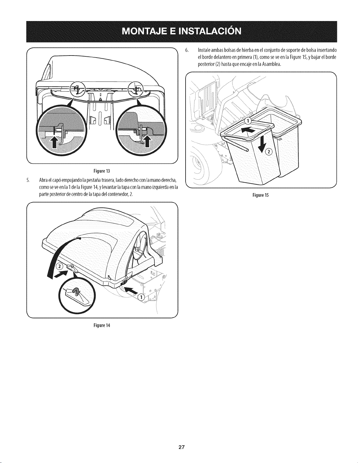
f "_ 6. Instaleambasbolsasdehierbaenelconjuntodesoportedebolsalnsertando
elbordedelanteroenprimera(1),comoseveenla Figure15,ybajarelborde
posterior(2)hastaqueencajeenlaAsamblea.
k,, _,
Figure 13
5. Abraelcap6empujandolapestaffatrasera,ladoderechoconlamanoderecha,
comoseveenla1delaFigure14,ylevantarlatapaconlamano[zqulerdaenla
parteposteriordecentrodelatapadelcontenedor,2.
Figure15
Figure 14
27
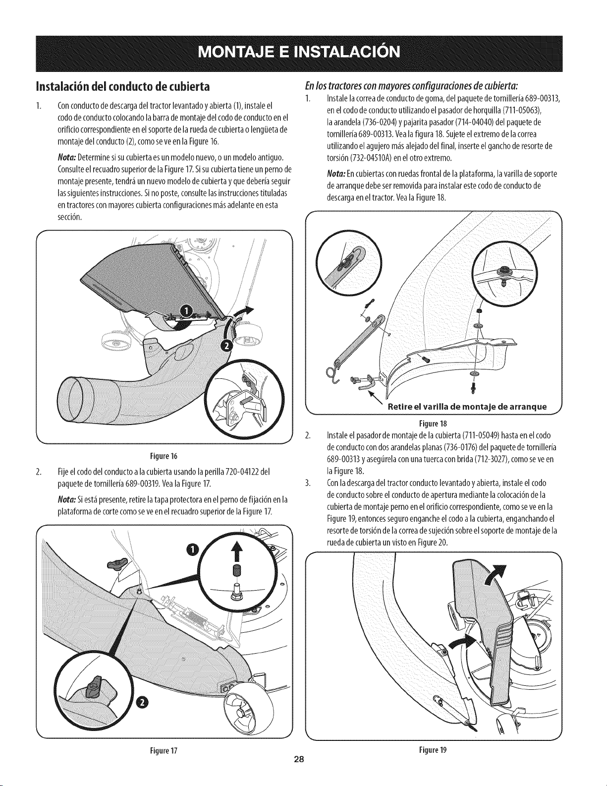
Instalaci6ndeiconductodecubierta
Conconductodedescargadeltractorlevantadoy abierta(I), instaleel
cododeconductocolocandolabarrademontajedelcododeconductoenel
orifido correspondienteenelsoportedelaruedade cubiertao lengiJetade
montajedelconducto(2),comoseveenla Figure16.
Nora:Determinesisucubiertaesunmodelonuevo,o un modeloantiguo.
Consulteelrecuadrosuperiorde laFigure17.Sisucubiertatieneun pernode
montajepresente,tendr_un nuevomodelode cubiertay quedeberiaseguir
lassiguientesinstrucdones.Sino poste,consultelasinstrucdonestituladas
entractoresconmayorescubiertaconfiguradonesm_sadelanteenesta
secd6n.
U
//
/
Figure16
Fijeelcododelconductoa lacubiertausandolaperilla720-04122del
paquetedetornilleria689-00319.VealaFigure17.
Nota:Siest_presente,retire latapaprotectoraenel pernode fijad6nenla
plataformadecortecomoseveenel recuadrosuperiordela Figure17.
Enlos tractoresconmayoresconfiguradonesde cubierta:
1. Instalelacorreadeconductodegoma,delpaquetedetornilleria689-00313,
en elcododeconductoutilizandoel pasadordehorquilla(711-05063),
laarandela(736-0204)y pajaritapasador(714-04040)del paquetede
tornilleria689-00313.Vealafigura 18.Sujeteelextremode lacorrea
utilizandoel agujerom_salejadodelfinal,inserteel ganchode resortede
torsi6n(732-04510A)en elotroextremo.
Nora: Encubiertasconruedasfrontaldelaplataforma,la varillade soporte
dearranquedebeserremovidaparainstalarestecododeconductode
descargaeneltractor.Veala Figure18.
I
Rt I II d t d
e areevaraa era?, aJe earra,que
Figure18
2. Instaleelpasadorde montajede lacubierta(711-05049)hastaenelcodo
deconductocondosarandelasplanas(736-0176)delpaquetedetornilleria
689-00313yasegtirelaconunatuercaconbrida(712-3027),comoseveen
laFigure18.
3. Conladescargadeltractorconductolevantadoyabierta,[nstaleel codo
deconductosobreel conductodeaperturamediantelacolocad6ndela
cubiertademontajepernoenel orifido correspondiente,comoseveen la
Figure19,entoncesseguroengancheel codoa lacubierta,enganchandoel
resortedetorsi6nde lacorreadesujed6nsobreel soportedemontajedela
ruedadecubiertaunvistoen Figure20.
Figure17 Figure19
28
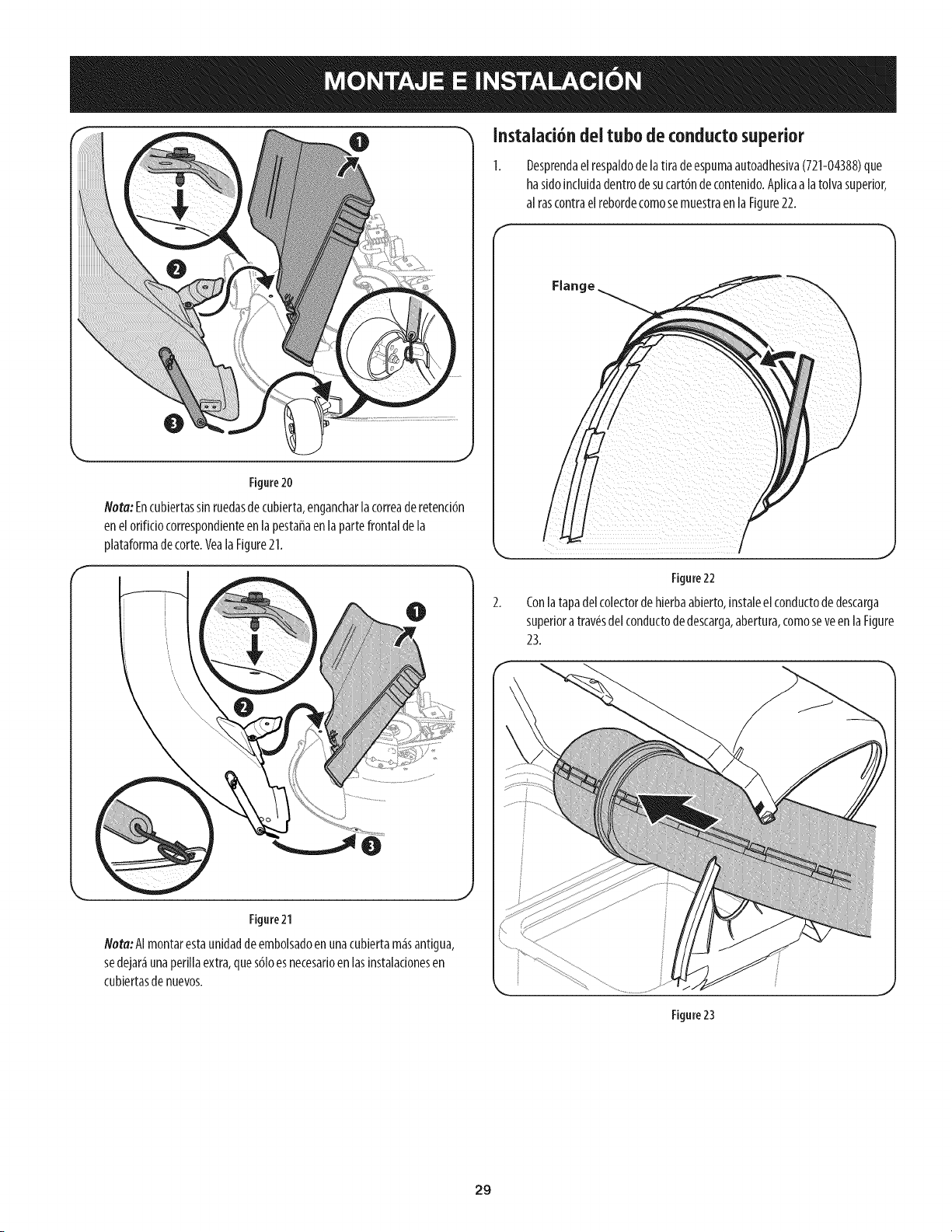
0 Instalad6ndel tubode conductosuperior
Figure20
Nora:Encubiertassinruedasdecubierta,engancharlacorreaderetenci6n
enelorificiocorrespondienteen lapestaffaenla partefrontaldela
plataformadecorte.Veala Figure21.
Figure21
Nora:AImontarestaunidaddeembolsadoenunacubiertam_santigua,
sedejar_unaperillaextra,ques61oesnecesarioen lasinstalacionesen
cubiertasde nuevos.
Desprendael respaidode la tiradeespumaautoadhesiva(721-04388)que
ha sidoincluidadentrodesucart6nde contenido.Aplicaa latolvasuperior,
al rascontraelrebordecomosemuestraenlaFigure22.
Figure22
Conlatapadelcolectordehierbaabierto,instaleel conductodedescarga
superiora tray,s delconductodedescarga,abertura,comoseveen laFigure
23.
Figure23
29
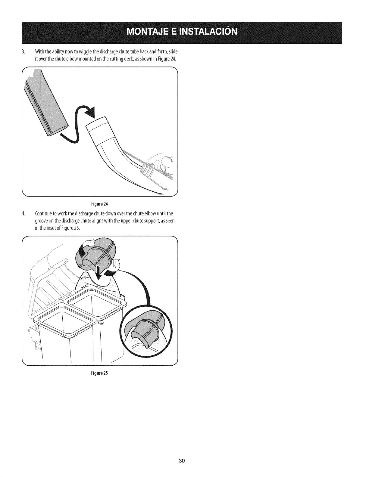
3. Withtheabilitynowtowigglethedischargechutetubebackandforth,slide
itoverthechuteelbowmountedonthecuttingdeck,asshowninFigure24.
4.
Figure24
Continueto workthedischargechutedownoverthechuteelbowuntil the
grooveonthe dischargechutealignswith theupperchutesupport,asseen
intheinsetof Figure25.
Figure25
30
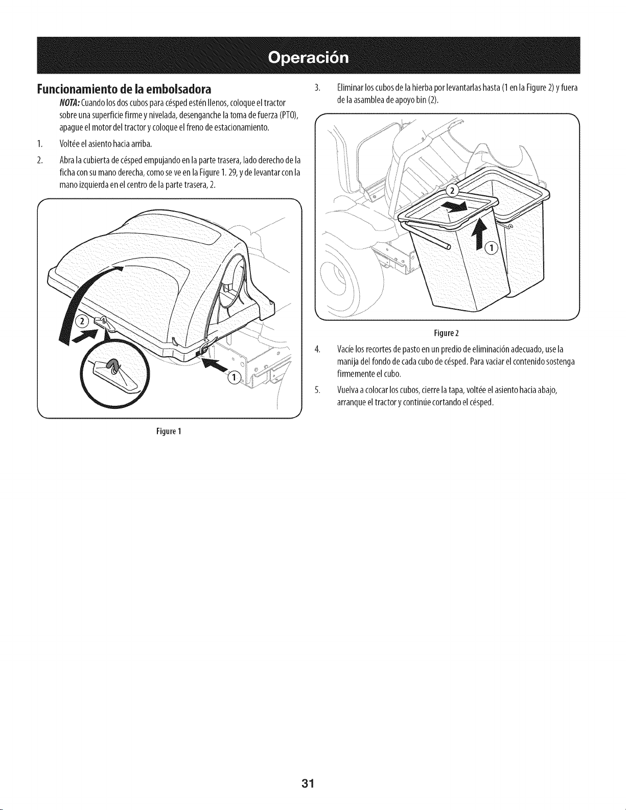
Fundonamiento de ia embolsadora
NOTA:Cuandolosdoscubosparac#spedest#nIlenos,coloqueel tractor
sobreunasuperfidefirmeynivelada,desenganchelatomade fuerza(PTO),
apagueel motordeltractory coloqueelfrenodeestadonamiento.
1. Volt_eelasientohadaarriba.
Abralacubiertade c#spedempujandoenlapartetrasera,ladoderechodela
fichaconsumanoderecha,comoseveen laFigure1.29,y delevantarconla
manoizquierdaen elcentrode la partetrasera,2.
Eliminarloscubosde lahierbaporlevantarlashasta(1enla Figure2)yfuera
de laasambleadeapoyobin(2).
Figure 1
Figure2
Vacielosrecortesdepastoenunprediode eliminad6nadecuado,usela
manijadelfondodecadacubodec#sped.Paravadarelcontenidosostenga
firmementeelcubo.
Vuelvaacolocarloscubos,derrelatapa,volt#eel asientohadaabajo,
arranqueeltractory contint_ecortandoelc#sped.
31

This page intentionally left blank. Use this page to make any notes regarding your bagger.
32