

perator's
I:RnFrSMRN°
TWO BiN BAGGER
Model No. 247.240193
• Espanol, p. 18
iMPORTANT:
Read and follow all Safety
Rules and instructions before
operating this equipment.
For answers to your questions about
this product, call:
1-800=659=5917
Craftsman Tractor Help Line
7 am = 7 pm CT, Mort. =Sun.
Sears Brands Management Corporation, Hoffman Estates, IL 60179 U.S.A.
Visit our website: www.craftsman.com FormNo.769-08766
(February1,2013)

Safe Operation Practices ..........................................................3-4
Slope Guide ......................................................................................5
Contents of Carton & Hardware Packs ................................6-7
Assembly and Installation .....................................................8-14
Operation ........................................................................................15
Parts List .....................................................................................16-17
Espaffol .............................................................................................18
CRAFTSMAN ONE YEAR FULL WARRANTY
FORONEYEARfromthe dateof purchase,this productis warrantedagainstanydefectsin materialorworkmanship.Adefectiveproductwill bereplacedfreeof
charge.
Forwarrantycoveragedetailsto obtainfreereplacement,visit thewebsite:www.craftsman.com
Thiswarrantyis voidifthisproductiseverusedwhileprovidingcommercialservicesor if rentedto anotherperson.
Thiswarrantygivesyouspecificlegalrights,andyoumayalsohaveotherrightswhichvaryfromstateto state.
SearsBrandsManagement, Hoffman Estates,IL60179
© SearsBrands,LLC 2
Thissymbolpointsoutimportantsafety instructionswhich,if not
followed, could endangerthe personalsafetyand/orproperty of
yourselfandothers. Readandfollow all instructionsin this manual
beforeattempting to operatethis machine.Failureto complywith these
instructionsmay resultinpersonalinjury.Whenyouseethis symbol,HEED
ITSWARNING!
CALiFORNiA PROPOSITION 65
EngineExhaust,someof itsconstituents, andcertainvehiclecomponents
contain or emit chemicalsknownto Stateof Californiato causecancerand
birth defectsor other reproductiveharm.
Battery posts,terminals,and relatedaccessoriescontain leadand lead
compounds,chemicalsknownto the Stateof Californiatocausecancerand
reproductive harm.Washhandsafter handling.
Thismachinewasbuilt to beoperatedaccordingto the safeoperation
practicesin this manual.Aswith anytype of powerequipment,
carelessnessor error on the partof the operatorcanresultin seriousinjury.
Thismachineiscapableof amputating fingers, hands,toesandfeet and
throwingdebris. Failureto observethe following safety instructionscould
resultin seriousinjuryor death.
Your Responsibility--Restrict the useof this powermachineto
personswho read,understandandfollow the warningsand instructionsin
thismanualandon the machine.
SAVETHESEINSTRUCTIONS!
GENERAL OPERATION
Read,understand,andfollowall instructionsonyourequipmentandintheir
manualsbeforeattemptingto assembleandoperate.Keepthismanualin
asafeplaceforfutureandregularreferenceandfor orderingreplacement
parts.
Tohelpavoidbladecontactor a thrownobjectinjury,keepbystanders,
helpers,childrenandpetsat least75feetfrom the mowerwhileit isin
operation.Stopmachineif anyoneentersthe area.
Thoroughlyinspecttheareawheretheequipmentisto beused.Remove
all stones,sticks,wire, bones,toys,andotherforeignobjectswhichcould
bepickedupandthrownbythe blade(s).Thrownobjectscancauseserious
personalinjury.
Alwayswearsafetyglassesor safetygogglesduringoperationandwhile
performinganadjustmentor repairto protectyoureyes.Thrownobjects
whichricochetcancauseseriousinjury to theeyes.
Donotoperatethe mowerwithoutthe dischargecoveror entiregrass
catcherin itsproperplace.A missingordamageddischargecoverorgrass
bagattachmentcomponentmayresultinthrownobjectsorbladecontact
injuries.
Donotput handsorfeetnearrotatingpartsor underthecuttingdeck.
Contactwith theblade(s)canamputatehandsandfeet.
Shutoff mower'sengineandwait forbladesto cometo acompletestop
beforeuncloggingmower'sdischargeopeningor baggerparts.
Slowdown beforeturning.Operatethemachinesmoothly.Avoiderratic
operationandexcessivespeed.Beawarethata grasscatcherattachmentcan
affectthehandlingcharacteristicsofyourmower.
Disengageblade(s),setparkingbrake,stopengineandwaituntil the
blade(s)cometo a completestopbeforeopeningbaggerattachment'stop
cover,removinggrasscatcher,emptyinggrass,uncloggingchute,removing
anygrassor debris,or makinganyadjustments.
Neverleavea runningmachineunattended.Alwaysturn off blade(s),place
transmissioninneutral,setparkingbrake,stopengineandremovekey
beforedismounting.
Yourmachineisdesignedto cut normalresidentialgrassof aheightno more
than 10".Donotattemptto mowthroughunusuallytall, drygrass(e.g.,
pasture)or pilesofdryleaves.Drygrassor leavesmaycontacttheengine
exhaustand/orbuildup onthe mowerdeckpresentinga potentialfire
hazard.
Ifsituationsoccurwhicharenotcoveredinthismanual,usecareandgood
judgment.
SLOPE OPERATION
Slopesarea majorfactorrelatedto lossofcontrolandtip-overaccidentswhichcan
resultinsevereinjuryordeath.Allslopesrequireextracaution.Ifyoucannotback
upthe slopeor if youfeel uneasyon it,do not mowit.
Foryoursafety,usethe SlopeGuideincludedaspart ofthismanualto measure
slopesbeforeoperatingthismachineon aslopedor hilly area.Ifthe slopeis greater
than 10degreesasshownonthe SlopeGuide,do notoperatethismachineon that
areaor seriousinjurycouldresult.
Do;
Mow upanddownslopes,not across.Exerciseextremecautionwhen
changingdirectionon slopes.
Watchforholes,ruts,bumps,rocks,orotherhiddenobjects.Uneventerrain
couldoverturnthe machine.Tallgrasscanhideobstacles.
Useslowspeed.Choosealow enoughspeedsettingsothatyouwill not have
to stoporshift whileon theslope.Tiresmaylosetractiononslopeseven
thoughthe brakesarefunctioningproperly.Alwayskeepmachineingear
whengoingdownslopesto takeadvantageof enginebrakingaction.
Followthe manufacturer'srecommendationsforwheelweightsor
counterweightsto improvestability.
Keepallmovementontheslopesslowandgradual.Donotmakesudden
changesinspeedordirection.Rapidengagementorbrakingcouldcause
thefrontofthemachinetoliftandrapidlyflipoverbackwardswhichcould
causeseriousinjury.
Avoidstartingorstoppingona slope.Iftires losetraction,disengagethe
blade(s)andproceedslowlystraightdowntheslope.
Do Not:
Donotturn onslopesunlessnecessary;then,turn slowlyandgradually
downhill,if possible.
Donotmowneardrop-offs,ditchesor embankments.Themowercould
suddenlyturn overif awheelisovertheedgeof acliff,ditch,orif anedge
cavesin.
Donottry to stabilizethe machinebyputtingyourfooton theground.
Donotuseagrasscatcheron steepslopes.
Donotmowon wetgrass.Reducedtractioncouldcausesliding.
GENERAL SERVICE
Beforecleaning,repairing,or inspecting,makecertainthe blade(s)andall
movingpartshavestopped.Disconnectthe sparkplugwire andground
againstthe engineto preventunintendedstarting.
Keepallnuts,bolts,andscrewstightto besuretheequipmentisinsafeworking
condition.
Nevertamperwith your mower'ssafetyinterlocksystemorother safetydevices.
Checktheir properoperationregularly.
Neverattempt to makeadjustmentsor repairswhile the mower'sengineisrunning.
Grasscatchercomponentsandthe dischargecoveraresubjectto wearanddamage
which couldexposemovingpartsorallow objectsto bethrown. Forsafety
protection,frequentlycheckcomponentsandreplaceimmediatelywith original
equipmentmanufacturer's(O.E.M.)partsonly,listedin this manual.Useof parts
which donot meetthe originalequipmentspecificationsmayleadto improper
performanceandcompromisesafety!
Maintainor replacesafetyandinstructionlabels,asnecessary.
SAFETY SYMBOLS
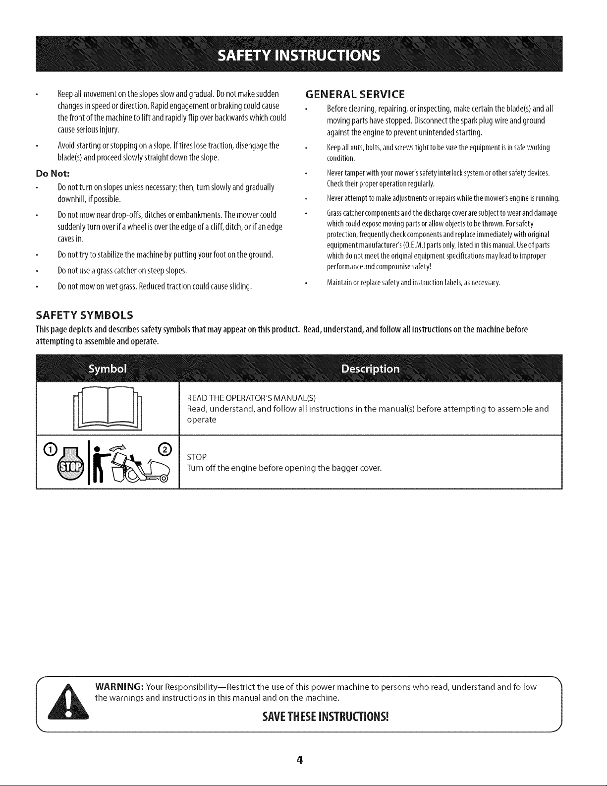
Thispagedepictsanddescribessafetysymbolsthat may appearon this product. Read,understand,andfollow all instructionson the machinebefore
attempting to assembleand operate.
%
READ THE OPERATOR'S MANUAL(S)
Read, understand, and follow all instructions in the manual(s) before attempting to assemble and
operate
STOP
Turn off the engine before opening the bagger cover.
WARNING: Your Responsibility--Restrict the use of this power machine to persons who read, understand and follow
the warnings and instructions in this manual and on the machine.
SAVETHESEINSTRUCTIONS!
4
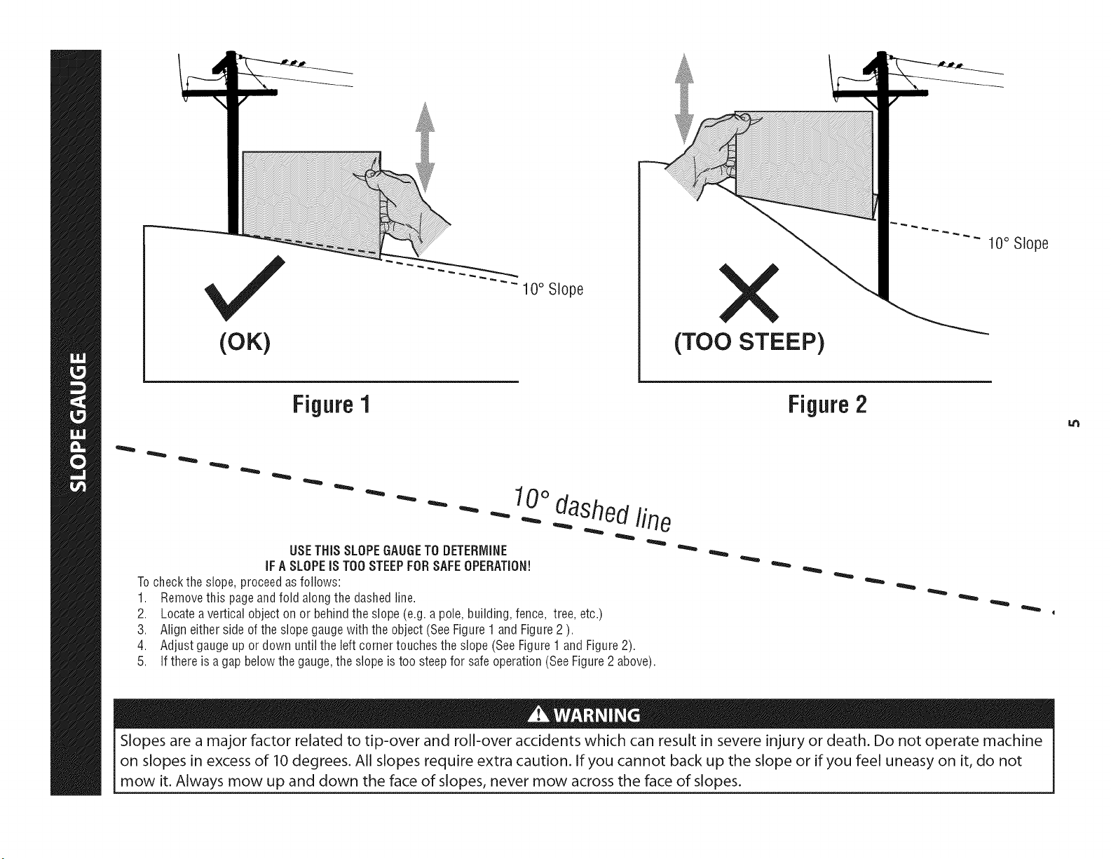
(OK)
10° Slope
(TOO STEEP)
10° Slope
Figure 1
USETHiSSLOPEGAUGETO DETERMINE
iFA SLOPEiS TOOSTEEPFORSAFEOPERATION!
Tocheckthe slope,proceedas follows:
1. Removethis pageandfold alongthe dashedline.
2. Locateavertical object on or behindthe slope(e.g.a pole,building,fence, tree, etc.)
3. Aligneither sideof the slopegaugewith the object (SeeFigure1 and Figure2 ).
4. Adjustgaugeup or down until the left cornertouchesthe slope(See Figure1 andFigure2).
5.
10odashedline
If there is a gapbelowthe gauge,the slope is too steepfor safeoperation(SeeFigure2 above).
Figure2
Slopes are a major factor related to tip-over and roll-over accidents which can result in severe injury or death. Do not operate machine
on slopes in excess of 10 degrees. All slopes require extra caution. If you cannot back up the slope or if you feel uneasy on it, do not
mow it. Always mow up and down the face of slopes, never mow across the face of slopes.
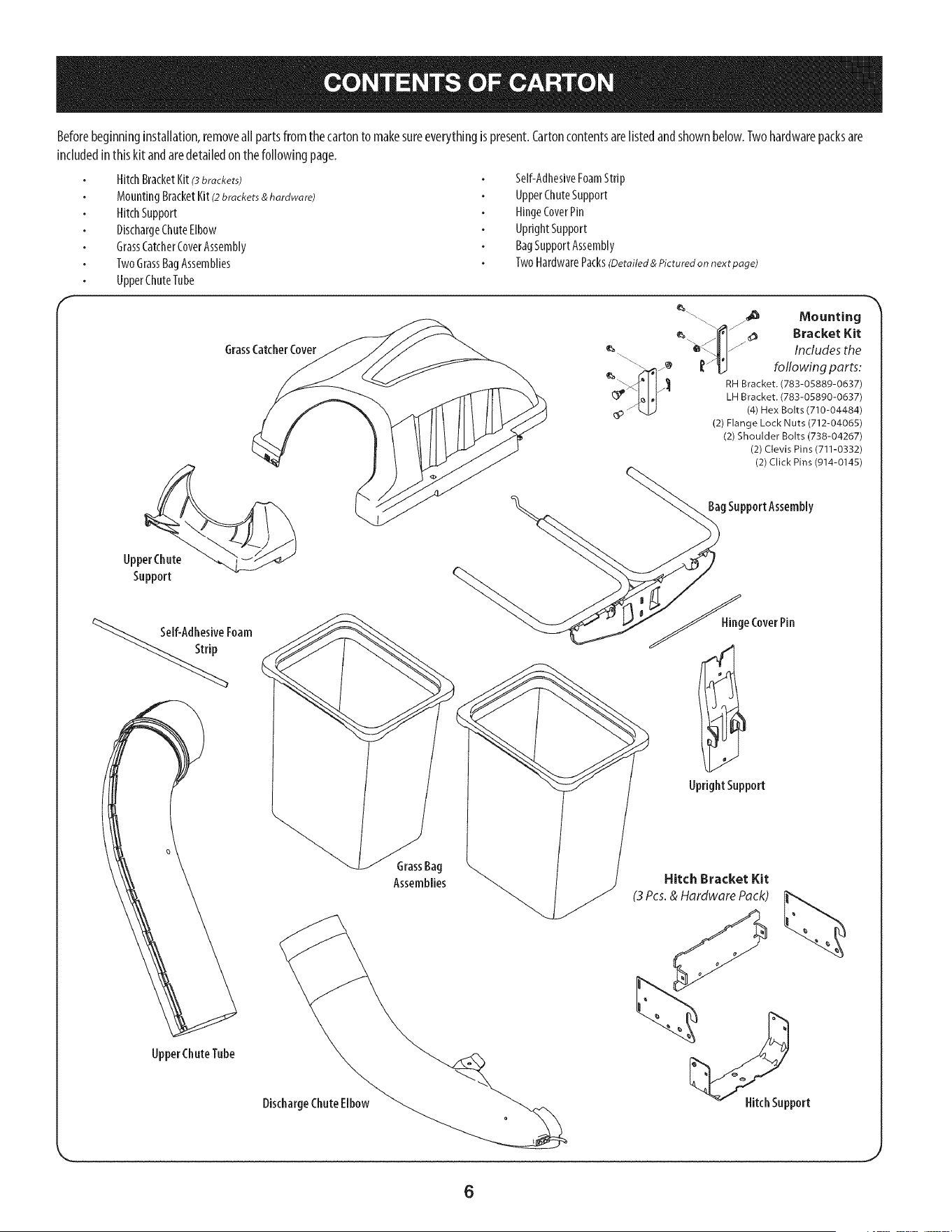
Beforebeginninginstallation,removeall partsfromthecartonto makesureeverythingis present.Cartoncontentsarelistedandshownbelow.Twohardwarepacksare
includedinthiskit andaredetailedon the followingpage.
HitchBracketKit(3brackets)
MountingBracketKit(2brackets & hardware)
HitchSupport
DischargeChuteElbow
GrassCatcherCoverAssembly
TwoGrassBagAssemblies
UpperChuteTube
Self-AdhesiveFoamStrip
UpperChuteSupport
HingeCoverPin
UprightSupport
BagSupportAssembly
TwoHardwarePacks(Detailed & Pictured on next page)
GrassCatcherCover
Upper Chute
Support
%_If-Adhesive Foam
_"_ \ ._ Mounting
/,,,"I'_ _ _ Bracket Kit
_'_ IJI/ Includes the
\\\_z_ ['_ following parts:
/__ RH Bracket. (783-05889-0637)
LH Bracket. (783-05890-0637)
_p- _ (4) Hex Bolts (710-04484)
(2) Flange Lock Nuts (712-04065)
(2) Shoulder Bolts (738-04267)
(2) Clevis Pins (711-0332)
(2) Click Pins (914-0145)
gSupportAssembly
_ge CoverPin
UprightSupport
UpperChuteTube
GrassBag
Assemblies
Hitch Bracket Kit
(3 Pcs.& Hardware Pack)
DischargeChuteElbow Hitch Support
6
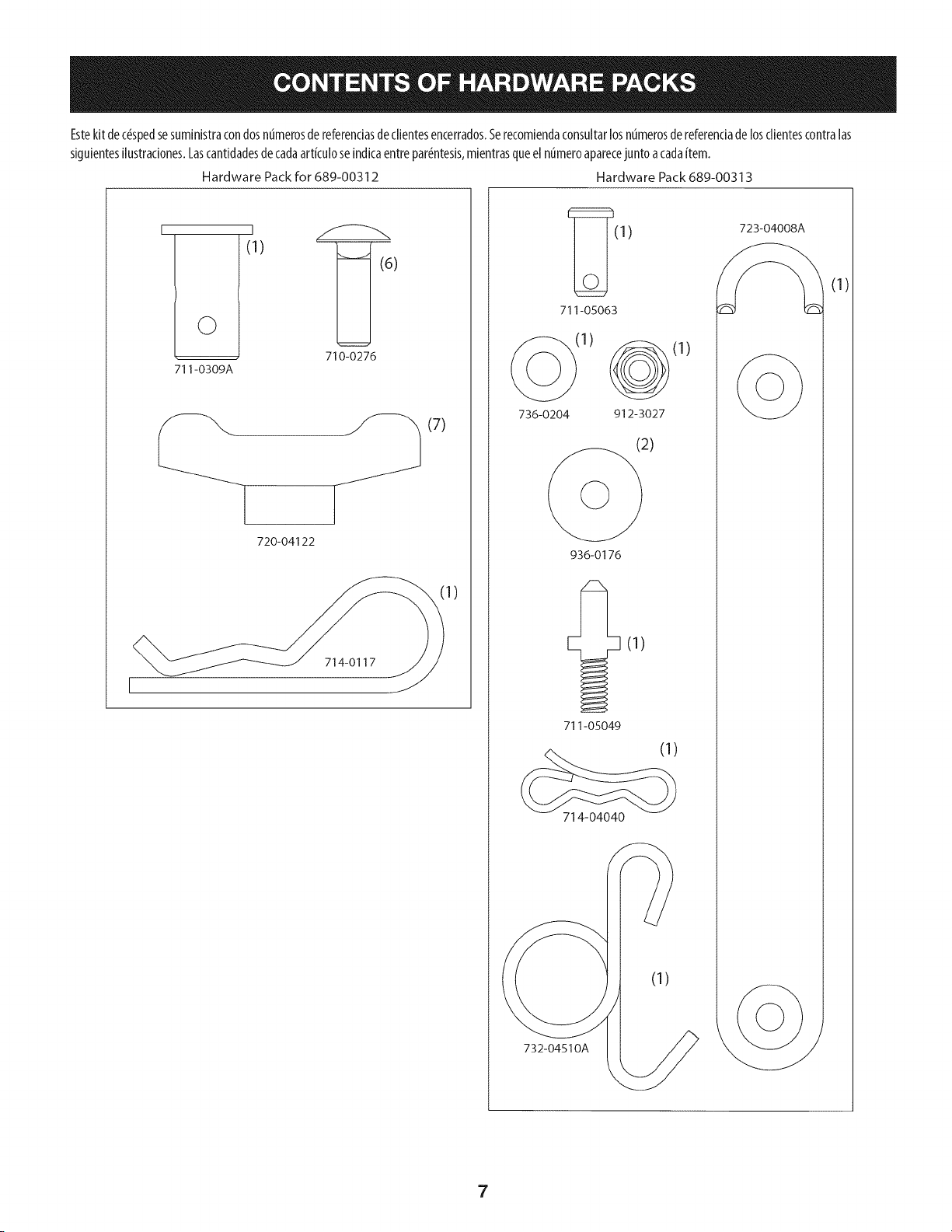
Estekit dec#spedsesuministracondosnumerosde referendasdeclientesencerrados.5erecomiendaconsuitarlosnumerosdereferenciadelosclientescontralas
siguientesilustraciones.Lascantidadesdecadaartkulo seindicaentrepar#ntesis,mientrasqueel ntimeroaparecejuntoacadaitem.
Hardware Pack for 689-00312 Hardware Pack 689-00313
I
©
711-0309A
I
(1)
)
710-0276
__ ._ (7)
720-04122
714-0117
1)
(1) 723-04008/__.
711-05063
(1)
736-0204 912-3027
936-0176
711-05049
714-04040
732-04510A
(1)
(1)
7
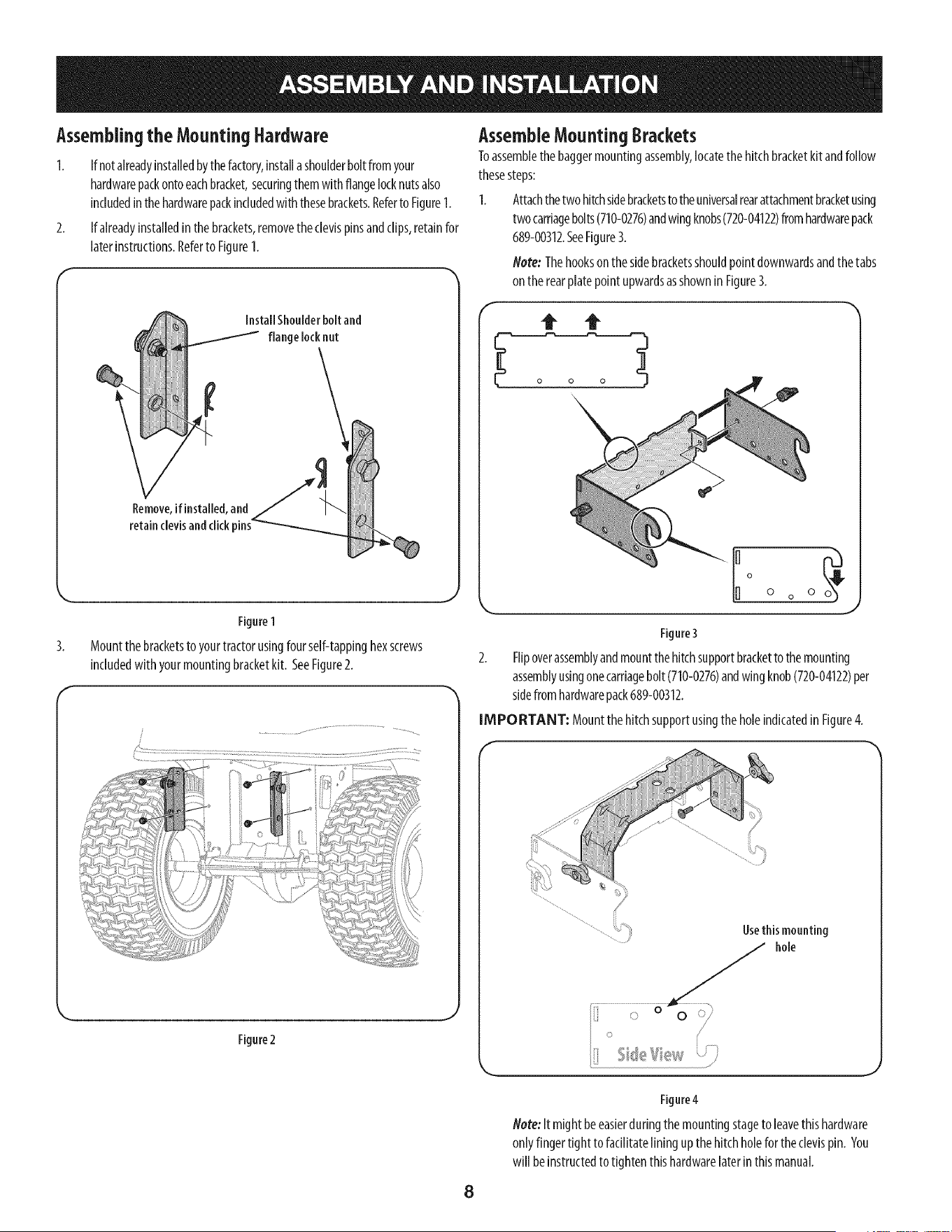
Assemblingthe Mounting Hardware
1. If notalreadyinstalledbythefactory,installashoulderboltfromyour
hardwarepackontoeachbracket,securingthemwith flangelocknutsalso
includedinthehardwarepackincludedwiththesebrackets.Referto Figure1.
2. If alreadyinstalledinthe brackets,removetheclevispinsandclips,retainfor
laterinstructions.Referto Figure1.
Figure1
3. Mountthebracketsto yourtractorusingfourself-tappinghexscrews
includedwith yourmountingbracketkit. SeeFigure2.
f
Figure2
AssembleMountingBrackets
Toassemblethebaggermountingassembly,locatethehitchbracketkit andfollow
thesesteps:
1. Attachthetwohitchsidebracketstothe universalrearattachmentbracketusing
twocarriagebolts(710-0276)andwingknobs(720-04122)fromhardwarepack
689-00312.SeeFigure3.
Note: Thehookson thesidebracketsshouldpointdownwardsandthe tabs
on the rearplatepointupwardsasshownin Figure3.
Io
0 o 0
J
Figure3
2. Flipoverassemblyandmountthe hitchsupportbracketto themounting
assemblyusingonecarriagebolt (710-0276)andwingknob(720-04122)per
sidefromhardwarepack689-00312.
IMPORTANT: MountthehitchsupportusingtheholeindicatedinFigure4.
Usethismounting
hole
Figure4
Note:It mightbeeasierduringthemountingstageto leavethishardware
onlyfingertight to facilitatelining upthe hitchholefortheclevispin. You
win be instructedto tightenthishardwarelaterin thismanual.
8
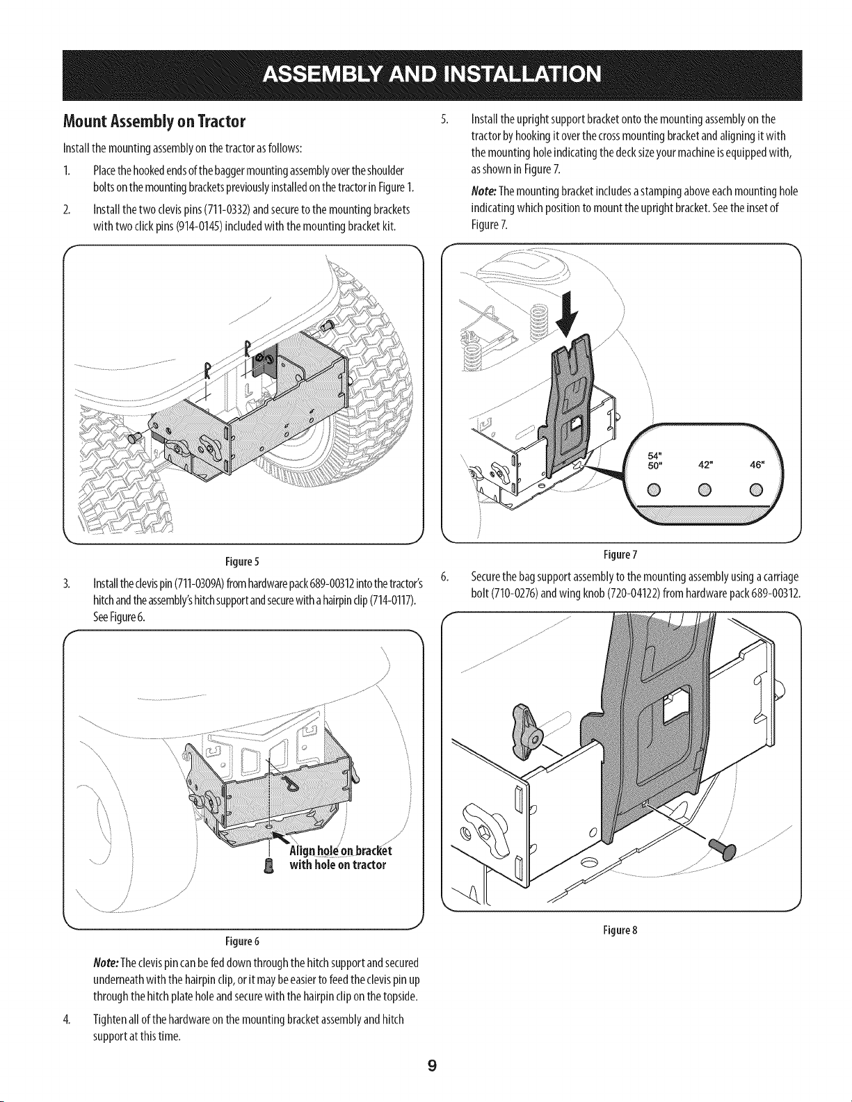
MountAssemblyon Tractor
Installthe mountingassemblyon thetractorasfollows:
1. Placethe hookedendsofthebaggermountingassemblyovertheshoulder
boltsonthe mountingbracketspreviouslyinstalledonthetractorin Figure1.
2. Installthetwo clevispins(711-0332)andsecureto the mountingbrackets
with twoclickpins(914-0145)includedwiththe mountingbracketkit.
Installtheuprightsupportbracketontothemountingassemblyonthe
tractorbyhookingit overthecrossmountingbracketandaligningit with
themountingholeindicatingthe decksizeyourmachineisequippedwith,
asshownin Figure7.
Note:Themountingbracketincludesastampingaboveeachmountinghole
indicatingwhichpositionto mounttheuprightbracket.Seetheinsetof
Figure7.
4.
Figure5
Installtheclevispin(711-0309A)fromhardwarepack689-00312intothetractor's
hitchandtheassembly'shitchsupportandsecurewithahairpinclip(714-0117).
SeeFigure6.
/
F\
with holeon tractor
Figure6
Note:Theclevispincanbefeddown throughthe hitchsupportandsecured
underneathwiththe hairpinclip,or it maybeeasierto feedtheclevispin up
throughthehitchplateholeandsecurewith thehairpinclip onthetopside.
Tightenallof the hardwareon the mountingbracketassemblyandhitch
supportatthistime.
Figure7
6. Securethe bagsupportassemblyto themountingassemblyusingacarriage
bolt (710-0276)andwing knob(720-04122)fromhardwarepack689-00312.
Figure8
9
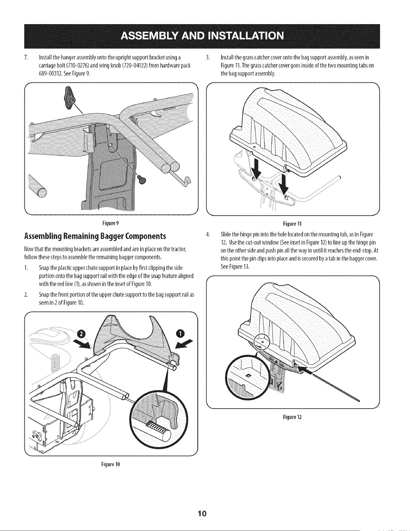
Installthe hangerassemblyontothe uprightsupportbracketusinga
carriagebolt (710-0276)andwingknob(720-04122)from hardwarepack
689-00312.SeeFigure9.
Installthegrasscatchercoverontothebagsupportassembly,asseenin
Figure11.Thegrasscatchercovergoesinsideof the two mountingtabson
thebagsupportassembly.
AssemblingRemainingBaggerComponents
Nowthat the mountingbracketsareassembledandareinplaceonthe tractor,
followthesestepsto assembletheremainingbaggercomponents.
1. Snaptheplasticupperchutesupportinplacebyfirst clippingthe side
portionontothe bagsupportrailwith the edgeof the snapfeaturealigned
with the redline (1),asshownin theinsetof Figure10.
2. Snapthefront portionof the upperchutesupportto the bagsupportrailas
seenin 2 of Figure10.
Figure 11
Slidethe hingepin intotheholelocatedonthemountingtab,asin Figure
12.Usethecut-outwindow(SeeinsetinFigure12)to lineup the hingepin
on the othersideandpushpinallthe wayinuntil it reachestheend-stop.At
thispointthepin clipsinto placeandissecuredbyatab in the baggercover.
SeeFigure13.
Figure12
Figure10
10
f "_ 7.
5.
6.
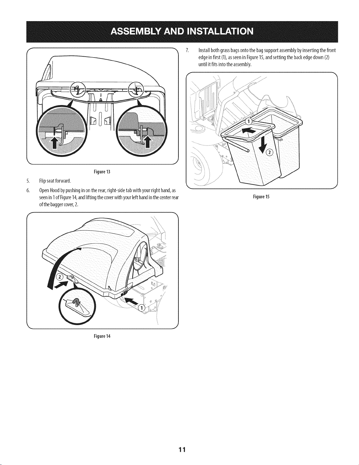
Figure13
Flipseatforward.
OpenHoodbypushingin ontherear,right-sidetabwith yourrighthand,as
seenin 1ofFigure14,andlifting thecoverwith yourleft handinthe centerrear
ofthebaggercover,2.
Installbothgrassbagsontothebagsupportassemblybyinsertingthe front
edgein first (1),asseeninFigure15,andsettingthebackedgedown(2)
until it fits into theassembly.
Figure15
Figure 14
11
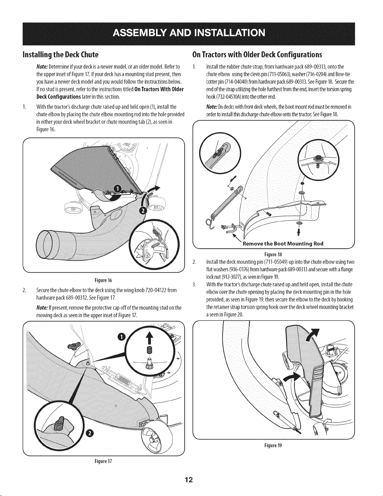
Installingthe DeckChute
Note:Determineif yourdeckisa newermodel,oran oldermodel.Referto
theupperinsetof Figure17.Ifyourdeckhasa mountingstudpresent,then
youhaveanewerdeckmodelandyouwouldfollowtheinstructionsbelow.
If nostudispresent,referto the instructionstitled OnTractorsWith Older
DeckConfigurationslaterin thissection.
Withthetractor'sdischargechuteraisedup andheldopen(1),installthe
chuteelbowbyplacingthe chuteelbowmountingrodintothe holeprovided
ineitheryourdeckwheelbracketorchutemountingtab(2),asseenin
Figure16.
Figure16
Securethechuteelbowtothe deckusingthewingknob720-04122from
hardwarepack689-00312.SeeFigure17.
Note:Ifpresent,removetheprotectivecapoffof the mountingstudonthe
mowingdeckasseeninthe upperinsetof Figure17.
OnTractorswith OlderDeckConfigurations
Installtherubberchutestrap,from hardwarepack689-00313,ontothe
chuteelbow usingtheclevispin(711-0S063),washer(736-0204)andBow-tie
cotterpin(714-04040)fromhardwarepack689-00313.SeeFigure18.Securethe
endofthestraputilizingthe holefurthestfromtheend,insertthetorsionspring
hook(732-04510A)intotheotherend.
Note:Ondeckswithfrontdeckwheels,thebootmountrodmustberemovedin
orderto installthisdischargechuteelbowontothetractor.SeeFigure18.
Remove the Boot Rod
Figure18
Installthedeckmountingpin (711-05049)up into thechuteelbowusingtwo
flat washers(936-0176)fromhardwarepack689-00313andsecurewithaflange
locknut (912-3027),asseeninFigure19.
With thetractor'sdischargechuteraisedupandheldopen,installthe chute
elbowoverthe chuteopeningbyplacingthe deckmountingpin in thehole
provided,asseeninFigure19,thensecurethe elbowto the deckby hooking
theretainerstraptorsionspringhookoverthe deckwheelmountingbracket
a seeninFigure20.
0
Figure17
Figure19
12
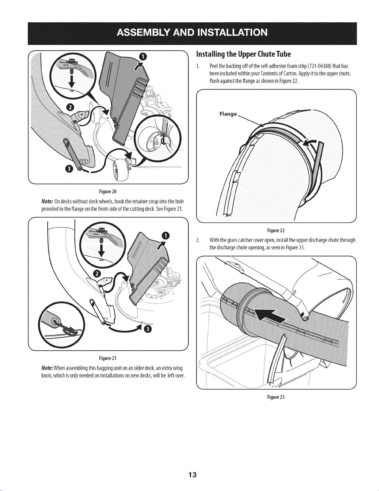
0 Installingthe UpperChuteTube
Figure20
Note:Ondeckswithoutdeckwheels,hookthe retainerstrapintothehole
providedintheflangeonthe front-sideof the cuttingdeck.SeeFigure21.
Figure21
Note:Whenassemblingthisbaggingunitonanolderdeck,anextrawing
knob,whichisonlyneededoninstallationson newdecks,will be left over.
Peelthebackingoff of theself-adhesivefoamstrip(721-04388)that has
beenincludedwithinyourContentsof Carton.Applyit to theupperchute,
flushagainsttheflangeasshowninFigure22.
/
Figure22
With thegrasscatchercoveropen,installthe upperdischargechutethrough
thedischargechuteopening,asseenin Figure23.
Figure23
13
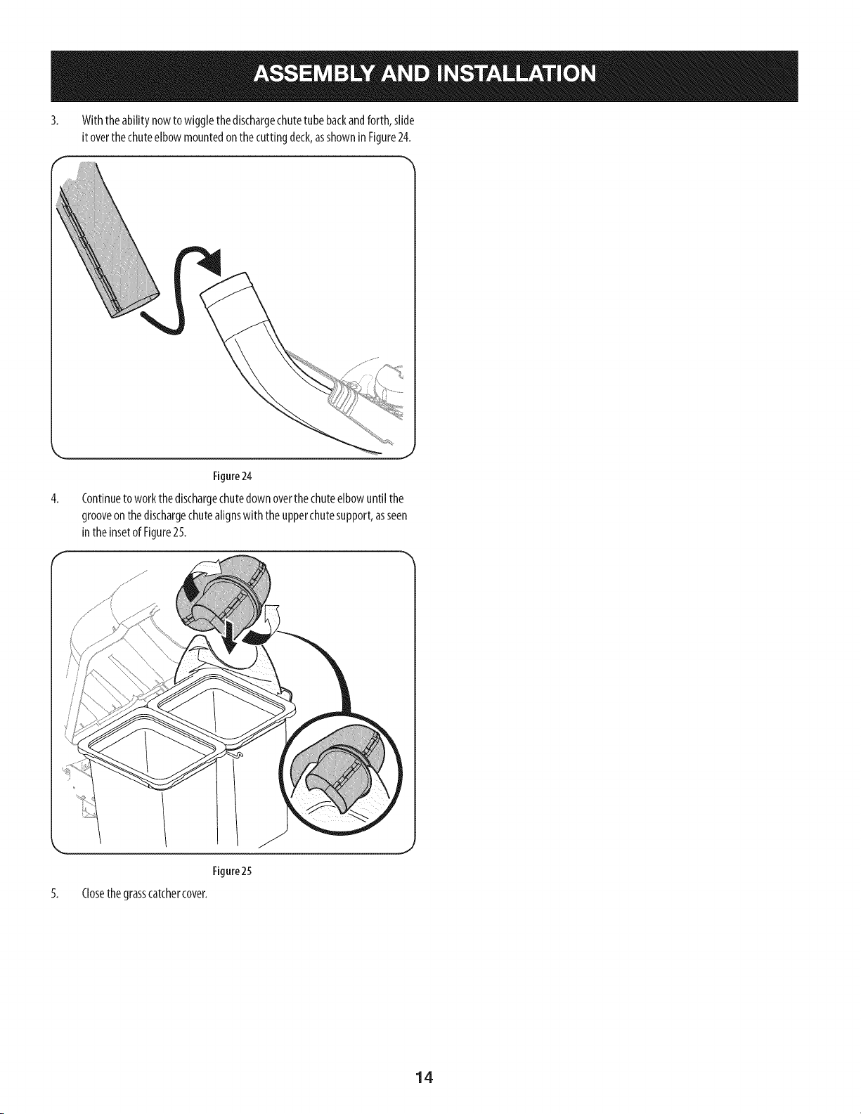
3. Withthe ability nowto wigglethedischargechutetubebackandforth, slide
it overthechuteelbow mountedon the cuttingdeck,asshownin Figure24.
4.
Figure24
Continueto workthe dischargechutedown overthe chuteelbowuntil the
grooveonthe dischargechutealignswith theupperchutesupport,asseen
intheinsetof Figure25.
5.
Figure25
Closethegrasscatchercover.
14
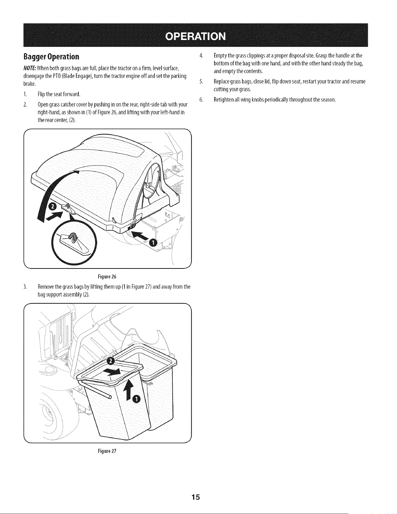
BaggerOperation
NOTE:Whenbothgrassbagsarefull, placethe tractoronafirm, levelsurface,
disengagethe PTO(BladeEngage),turnthetractorengineoffandsetthe parking
brake.
1.
2.
Fliptheseatforward.
Opengrasscatchercoverbypushinginon the rear,right-sidetabwith your
right-hand,asshownin (1)of Figure26,andlifting with yourleft-handin
therearcenter,(2).
4. Emptythegrassclippingsat aproperdisposalsite.Graspthe handleat the
bottomof the bagwith onehand,andwith theotherhandsteadythebag,
andemptythecontents.
5. Replacegrassbags,closelid,flip downseat,restartyourtractorandresume
cuttingyourgrass.
6. Retightenall wingknobsperiodicallythroughouttheseason.
Figure26
Removethe grassbagsbylifting them up(1 inFigure27)andawayfrom the
bagsupportassembly(2).
Figure 27
15
2O
22
28
25
19 j
j29
16

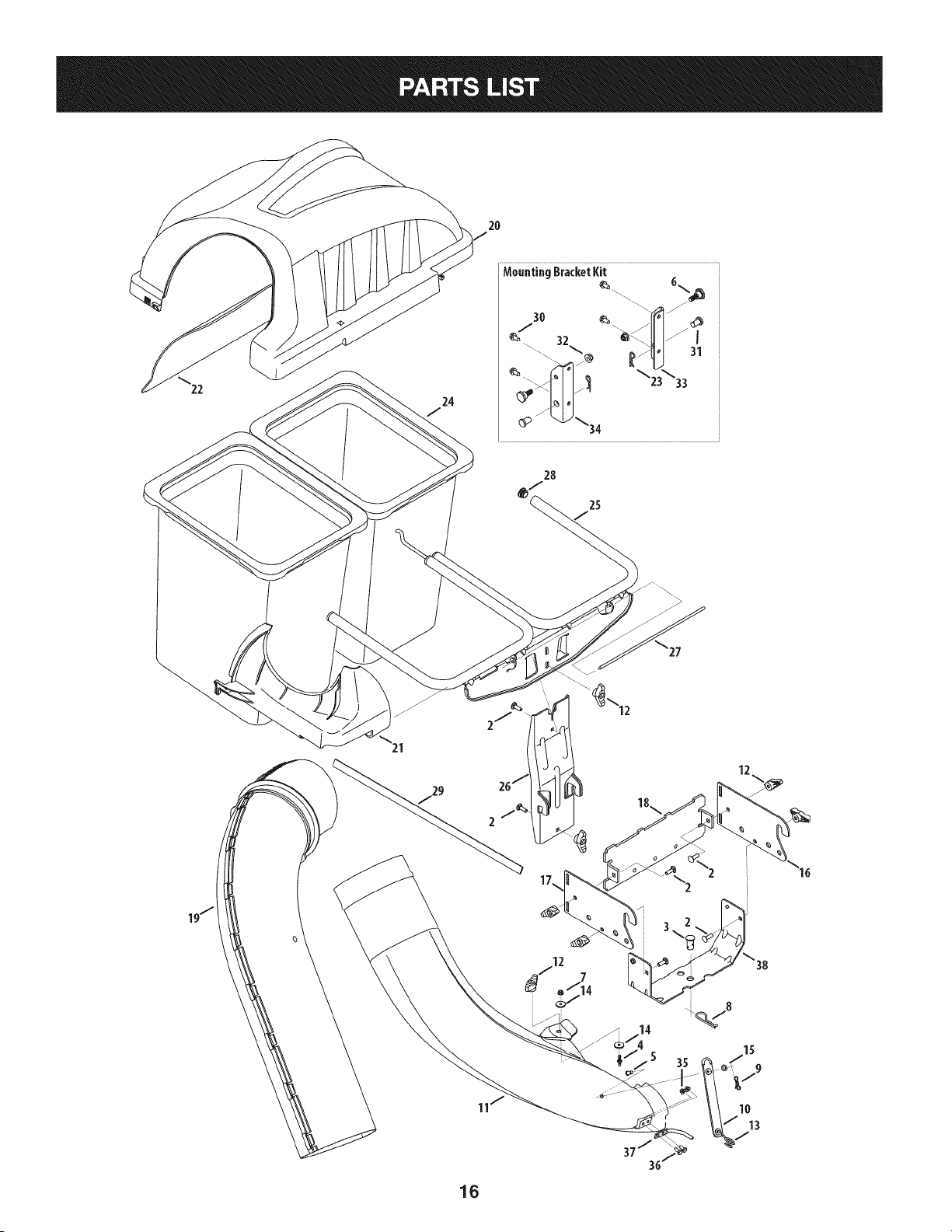
CRAFTSMANTWOBINBAGGERModel No.247.240193
Topurchasereplacementparts,call1-800-469-4663
!
Ref, I Part Number
1. 689-00304
2. 710-0276
3. 711-0309A
4. 711-05049
5. 711-05063
6. 738-04267
7. 912-3027
8. 714-0117
9. 714-04040
10. 723-04008A
11. 731-09173
12. 720-04122
13. 732-04510A
14. 936-0176
15. 736-0204
16. N/A _
17. N/A _
18. 783-08056-0637
19. 931-04295A
20. 931-04292
21. 731-06497
22. 731-06504
23. 914-0145
24. 964-04096A
25. 683-04461-0637
26. 683-04519-0637
27. 711-04988
28. 735-0246A
29. 721-04388
30. 710-04484
31. 911-0332
32. 712-04065
33. 783-05890A-0637
34. 783-05889A-0637
35. 712-04064
36. 710-0751
37. 747-06043
38. 783-08129
Description
Mounting Bracket Kit (Incl. ref. 16, 17, 18)
Carriage Screw, 5/16-18 x 1.00"
Clevis Pin, .62" Dia.
Attachment Pin, 1/4 x 0.66 Lg.
Clevis Pin, 5/16 x .75 Lg.
Shoulder Screw, .625 x .412
Flange Lock Nut, 1/4-20
Internal Cotter Pin, .148 x 3.00
Bow-Tie Cotter Pin, 72
Chute Strap, 6.00 Lg.
Bagger Discharge Chute Elbow
Wing Knob, 5/16-18
Torsion Spring Hook
Flat Washer, .265 x .938 x .120
Flat Washer, .344 x .62 x .033
Mounting Bracket, LH (Orderltem 1)
Mounting Bracket, RH (Orderltem 1)
Universal Bracket Support
Upper Discharge Chute
Double Bagger Cover Assembly
Upper Chute Support
Bagger Cover Screen
Click Pin, .092 x 1.64 Lg.
Grass-bag Assembly
Double Bag Support Assembly
Vertical Support Bracket
Cover Hinge Pin
End Plug
Self-Adhesive Foam Strip
Tap Screw, 5/16-18 x .750
Clevis Pin
Flange Lock Nut, 3/8-16
Mounting Bracket, LH
Mounting Bracket, RH
Flange Lock Nut, 1/4-20
Hex Head Screw, 1/4-20 x 620
Boot Mounting Rod
Hitch Support Bracket
_Order Reference 1
17
Sinstrucciones De Seguridad ............................................... 19-21
Contenido de la Caja ............................................................. 22-23
Montaje e Instalaci6n ........................................................... 24-30
Operaci6n ................................................................................... 31
Lista de piezas ...................................................................... 16-17
GARANTiACOMPLETADE UN ANO DE ARTESANO
DURANTEunaSodesde la fechade compra,esteproductoestAgarantizadocontracualquierdefectode materialo manode obra.Un producto
defectuososer_reemplazadosin cargo.
Paraquedetallesde lacoberturadegarantiaobtenerun reemplazolibre,visiteel sitio web: www.craftsman.com
EstagarantiaserAnula si esteproductose utilizamientrasque proporcionaservicioscomercialeso Si alquilaa otra persona.
Estagarantiale otorgaderechoslegalesespecificos,y ustedtambi_npuedetenerotros derechosquevariande estadoa estado.
Sears Brands ManagementCorporation., Hoffman Estates, IL 60179
© SEARSBRANDS,LLC 18
Lapresenciade este sirnboloindicaque setrata de instrucciones
irnportantesde seguridadque se debenrespetarpara evitar
ponerenpeligrosu seguridadpersonaly/o materialy lade otras
personas.Leay siga todaslas instruccionesdeeste manualantes
de poneren funcionarnientoestarn_quina.Si no respetaestas
instruccionespodriaprovocarlesionespersonales.Cuandoveaeste
sirnbolo,ipresteatenci6na la advertencia!
PROPOSICION 65 DE CALIFORNIA
Elescapedel motordeesteproducto,algunosde suscornponentes
y algunoscornponentesdelvehiculocontieneno liberansustancias
quirnicasqueelestadodeCaliforniaconsideraque puedenproducir
c_ncer,defectosde nacirnientouotrosproblernasreproductivos.
Losbornesde la bateriay los accesoriosafinescontienenplornoy
cornpuestosde plorno,sustanciasquirnicasque segOnIo estableci-
do pot el Estadode Californiacausanc_ncery da_osen el sisterna
reproductivo.Ldveselas manos despu_sde estaren contacto
con estoscomponentes.
Estarn&quinarueconstruidapara seroperadade acuerdocon
las reglasde seguridadcontenidasen este manual.AI igualque
concualquiertipo deequipo rnotorizado,undescuidoo errorpor
partedeloperadorpuedeproducirlesionesgraves.Esta rn&quina
es capazde arnputarrnanosy piesy dearrojarobjetoscon gran
fuerza.Deno respetarlas instruccionesde seguridadsiguientesse
puedenproducirlesionesgraveso larnuerte.
Su responsabilidad--Restrinja el usode esta rn_quina
rnotorizadaalas personasque lean,cornprendany respetenlas
advertenciase instruccionesqueaparecenen este manualyen la
rn_quina.
iGUARDEESTASINSTRUCCIONES!
Fundonamiento general
1. Lea, comprenda y respete todas las instrucciones que figuran
en el equipo yen los manuales antes de intentar armarlo y
hacerlo funcionar. Guarde este manual en un lugar seguro
para consultas futuras y peri6dicas, asi como para solicitar
repuestos.
2. Para ayudar a evitar una lesidn pot contacto con las cuchillas
o con un objeto que sea arrojado, mantenga a las personas
que observan, a los ayudantes, ni_os y mascotas alejados a no
menos de 25 metros de la m_quina mientras est_ funcionando.
Detenga la m_quina si alguien entra en la zona.
3. Revise minuciosamente el _irea donde se va a usar el equipo.
Retire todas las piedras, palos, cables, huesos, juguetes y otros
objetos extrahos que podrian ser recogidos y arrojados por la
accidn de las cuchillas. Los objetos arrojados por la m_quina
pueden causar lesiones graves.
4. Para protegerse los ojos, utilice siempre galas o lentes de
seguridad mientras opera la m&quina o mientras la ajusta
o repara. Los objetos arrojados que rebotan pueden causar
lesiones oculares graves.
5. Nunca opere la cortadora de c_sped sin tenet bien colocada
la cubierta de descarga o el colector de c_sped. Si falta o
est_ da_ada la cubierta de descarga oun componente del
accesorio embolsador puede resultar en lesiones por contacto
con la cuchilla o con objetos arrojados.
6. No ponga las manos ni los pies cerca de las piezas rotatorias ni
debajo de la plataforma de corte. El contacto con las cuchillas
puede resultar en la amputacidn de una mano o pie.
7. Apague el motor de la cortadora de c_sped y espere que
las cuchillas se detengan totalmente antes de desbloquear
la abertura de descarga de la cortadora o las piezas de la
embolsadora.
8. Reduzca la velocidad antes de girar. Opere la m_quina de
forma pareja. Evite el funcionamiento err_tico y la velocidad
excesiva. Tenga en cuenta que el accesorio colector de c6sped
puede afectar las caracteristicas de manejo de su cortadora.
Fundonamiento en pendientes
Las pendientes son un factor importante en los accidentes
ocasionados por p_rdida de control y vuelcos que pueden causar
lesiones graves e incluso la muerte. Los accesorios tambien pueden
afectar la estabilidad de la m_iquina. La operaci6n en pendiente
requiere mayor precaucidn.
Para seguridad, use el medidor de pendientes que se incluye como
parte de este manual para estimar el _ingulo de la pendiente antes
de hacer funcionar la m_iquina en una zona inclinada. Si la pendiente
es mayor a 10 grados en el medidor, no opere la cortadora con el
accesorio embolsador en ese sector, pues podria causar lesiones
graves.
I-lagaIo siguiente:
1. Corte hacia arriba y abajo de las pendientes, no en forma
transversal. Tenga sumo cuidado al cambiar de direcci6n en
una pendiente.
2. Est_ atento a los hoyos, surcos, baches, rocas, u otros objetos
ocultos. El terreno desnivelado puede voltear la m_quina. El
pasto alto puede ocultar obst_iculos.
3. Conduzca a baja velocidad. Elija una velocidad Io
suficientemente baja como para no tenet que detenerse
o cambiar de marcha mientras est,1 en la pendiente. Los
neum&ticos pueden perder tracci6n en las pendientes aun
cuando los frenos funcionen correctamente. Mantenga
la m_quina siempre en velocidad cuando desciende una
pendiente, para poder frenar con el motor.
19
4. Siga las recomendaciones del fabricante sobre pesos y
contrapesos de las ruedas, para mejorar la estabilidad.
5. Haga que todos los movimientos en las pendientes sean
lentos y graduales. No cambie repentinamente la velocidad
ni la direcci6n. Un frenado o cambio de velocidad repentinos
pueden causar que el frente de la m_iquina se levante y d_ una
voltereta hacia atr_is, Io que podria causar lesiones graves.
6. Evite arrancar o detenerse en una pendiente. Si los neum_iticos
pierden traccidn, desenganche las cuchillas y descienda
lentamente la pendiente.
No haga Iosiguiente:
I. No gire en una pendiente a menos que sea imprescindible. De
ser posible, gire lenta y gradualmente cuesta abajo.
2. No corte el c_sped cerca de barrancos, zanjas o terraplenes. La
cortadora de c_sped podria volcarse repentinamente si una de
las ruedas estuviera sobre el borde de un acantilado o zanja, o
si un borde se desmoronara.
3. No intente estabilizar la m_iquina poniendo el pie en el suelo.
4. No utilice un colector de c_sped en pendientes empinadas.
5. No corte el c_sped humedo. Una reducci6n en tracci6n puede
causar derrapes.
Sewido general
I. Antes de limpiar, reparar o inspeccionar la m_quina,
compruebe que las cuchillas y todas las piezas m6viles se
hayan detenido. Desconecte el cable de la bujia y p6ngalo
haciendo masa contra el motor para evitar que arranque
accidentalmente.
2. Mantenga todas las tuercas, pernos y tornillos bien ajustados
para asegurarse de que el equipo est,1 en condiciones seguras
de operaci6n.
3. Nunca intente violar el sistema de bloqueo de seguridad u
otros mecanismos de seguridad de la cortadora. Controle
peri6dicamente que funcionan correctamente.
4. No intente nunca hacer ajustes o reparaciones a la cortadora
mientras el motor est,1 en marcha.
5. Los componentes del colector de c_sped y la cubierta de
descarga est_fin sujetos a desgaste y dahos que podrian dejar
expuestas piezas que se mueven o permitir que se arrojen
objetos. Para proteger su seguridad, verifique frecuentemente
todos los componentes y reempl_icelos inmediatamente
unicamente con piezas de los fabricantes del equipo original
(O.E.M.) indicados en este manual. El uso de piezas que no
cumplen con las especificaciones del equipo original puede
resultar en rendimiento inadecuado y puede poner en peligro
la seguridad.
6. Mantenga o reemplace las etiquetas de seguridad y de
instrucciones segun sea necesario.
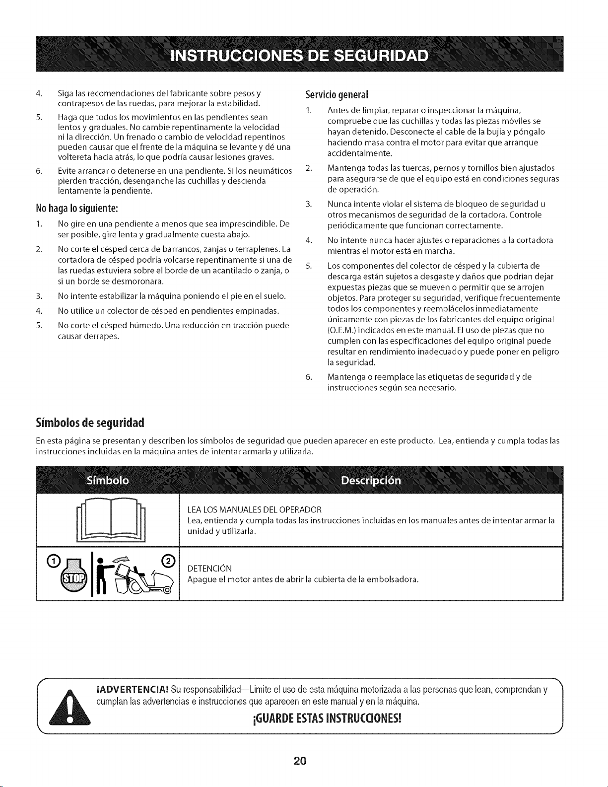
Simbolosde seguridad
En esta p_gina se presentan y describen los simbolos de seguridad que pueden aparecer en este producto. Lea, entienda y cumpla todas las
instrucciones incluidas en la m_quina antes de intentar armarla y utilizarla.
LEA LOS MANUALES DEL OPERADOR
Lea, entienda y cumpla todas las instrucciones incluidas en los manuales antes de intentar armar la
unidad y utilizarla.
DETENCION
Apague el motor antes de abrir la cubierta de la embolsadora.
IADVERTENCIA! Su responsabilidad--Limiteel uso deesta m&quinamotorizadaalas personasque lean,comprendany
cumplanlasadvertenciase instruccionesqueaparecenen este manualyen la m&quina.
iGLIARDEESTASINSTRL!CCIONES!
2O
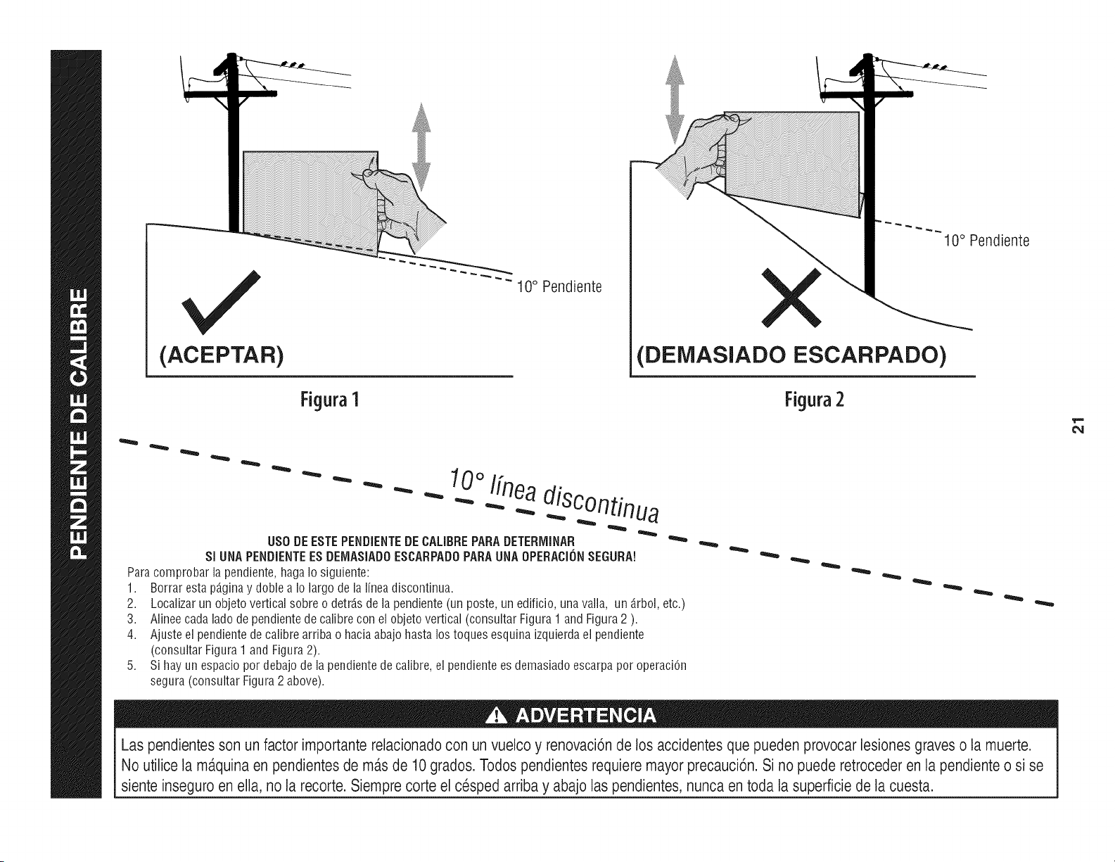
(ACEPTAR)
Figura1
"" 10 ° Pendiente
10° Pendiente
(DEiVIASlADO ESCARPADO)
Figura2
0oI[nea
- - " "" - _ .-...diSC°ntinua
US0 DEESTEPENDIENTEDECALIBREPARADETERiVIINAR
SI UNAPENDiENTEESDEIV1ASiADOESCARPADOPARAUNAOPERACi(_NSEGURA!
Paracomprobarla pendiente,hagaIosiguiente:
1. Borrarestap_.ginay doblea Io largodelalineadiscontinua.
2.
3.
4.
Localizarun objetoverticalsobreo detrJ.sde la pendiente(un poste,unedificio,unavalla, un _.rbol,etc.)
Alineecadaladodependientedecalibrecon elobjetovertical(consultarFigura1 andFigura2 ).
Ajusteel pendientede calibrearribao haciaabajo hastalos toquesesquinaizquierdael pendiente
(consultarFigura1 and Figura2).
Sihayun espaciopordebajodela pendientede calibre,el pendientees demasiadoescarpapor operaciOn
segura(consultarFigura2 above).
Las pendientesson un factor importante relacionadocon un vuelco y renovaci6n de los accidentesque pueden provocar lesiones graves o la muerte.
No utilice la m_.quinaen pendientes de m_.sde 10grados. Todos pendientesrequiere mayor precauci6n. Si no puede retroceder en la pendiente o si se
siente inseguro en ella, no la recorte. Siempre corte el cesped arriba y abajo laspendientes, nunca en toda la superficie de la cuesta.

Antesde comenzarlainstalad6n,quitetodaslaspiezasdelacajaparaasegurarsedequetodoest_presente.Contenidodelacajaseenumerany semuestraacontinuad6n.
Dospaquetesde hardwareseincluyenenestekit y sedetallanen lap_ginasiguiente.
Juegodesoportedeenganche(3 soportes)
SoportedemontajeKit(2 soportesy hardware)
EngancheSoporte
CododedescargaChute
Montajede latapadelcolectorde hierba
DosAsambleasGrassBag
Tubosuperiorde latolva
AutoadhesivoFranjadeespuma
Soportesuperiorde la tolva
PasadorCubierta
Soportevertical
BolsaAsambleaSoporte
D.ospaquetesde hardware(detalladosy apareceenlap_gina
slgulen_e)
e_
z,,g,
_.\ /_11_ Kit desoporte
de montaje
/_ Incluye las
siguientes partes:
RH Bracket. (783-05889-0637)
LH Bracket. (783-05890-0637)
(4) Hex Bolts (710-04484)
(2) Flange Lock Nuts (712-04065)
(2) Shoulder Bolts (738-04267)
(2) Clevis Pins (711-0332)
(2) Click Pins (914-0145)
22

Estekitdecolectordehierbavienecondosnt_merosdereferendadedienteadjunto.Porfavorrevisesusnt_merosdereferendadeclientecontralassiguientes
Hustradones.LascantMadesparacadaartkuloapareceentrepar_ntesismientrasqueelntimerodepiezacotizacercadecadaelemento.
HardwarePackfor689-00312 HardwarePack689-00313
I
©
711-0309A
_.J
(1)
710-0276
(7)
720-04122
714-0117
1)
_(1) 723-04008/_
711-05063
:1)
736-0204 912-3027
936-0176
711-05049
714-04040
732-04510A
(1)
(1)
23
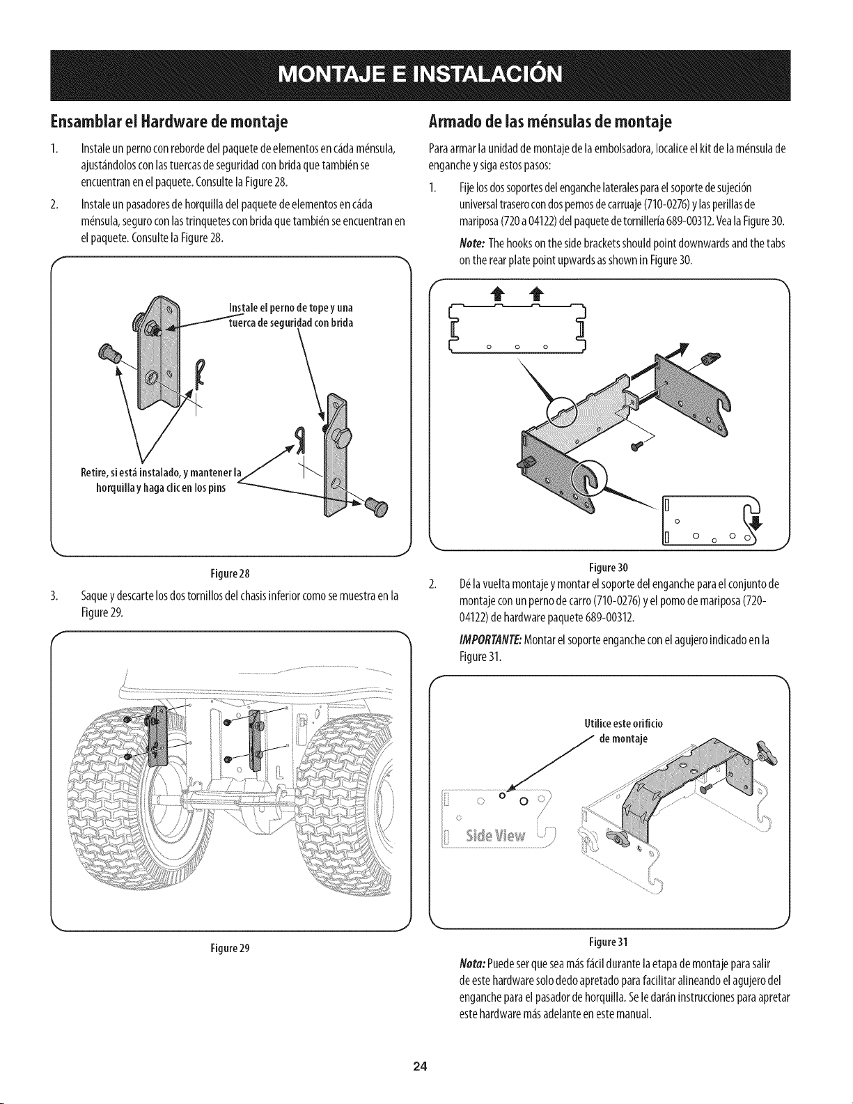
Ensamblarel Hardware demontaje
1. Instaleunpernoconrebordedelpaquetedeelementosenc_dam6nsula,
ajust_ndolosconlastuercasdeseguridadconbridaquetambi6nse
encuentranenelpaquete.ConsultelaFigure28.
2. Instaleunpasadoresdehorquilladelpaquetedeelementosenc_da
m6nsula,seguroconlastrinquetesconbridaquetambi_nseencuentranen
elpaquete.ConsultelaFigure28.
Instale el pernode topey una
seguridad conbrida
Retire,si est_ instalado,y mantener la
horquillay hagadic en los pins
Figure28
Saquey descartelosdostornfllosdelchasisinferiorcomosemuestraenla
Figure29.
Armadodeiasm nsuias de montaje
Paraarmarla unidadde montajedela embolsadora,Iocaliceelkit de lam_nsulade
enganchey sigaestospasos:
1. Fljelosdossoportesdelenganchelateralesparael soportedesujeci6n
universaltraserocondospernosdecarruaje(710-0276)y lasperfllasde
marlposa(720a04122)delpaquetedetornlller[a689-00312.VealaFigure30.
Note: Thehookson thesidebracketsshouldpointdownwardsandthe tabs
on the rearplatepointupwardsasshownin Figure30.
Figure30
D_lavueltamontajey montarelsoportedelengancheparaelconjuntode
montajeconunpernodecarro(710-0276)y el pomodemariposa(720-
04122)dehardwarepaquete689-00312.
IMPORTANTE:Montarelsoporteengancheconelagujeroindicadoenla
Figure31.
Utiliceesteorifido
demontaje
Figure 29
Figure31
I_ota: Puedeserqueseam_sf_dl durantela etapade montajeparasallr
deestehardwaresolodedoapretadoparafadlitar alineandoelagujerodel
engancheparael pasadorde horquilla.Sele dar_n[nstrucdonesparaapretar
estehardwarem_sadelanteenestemanual.
24
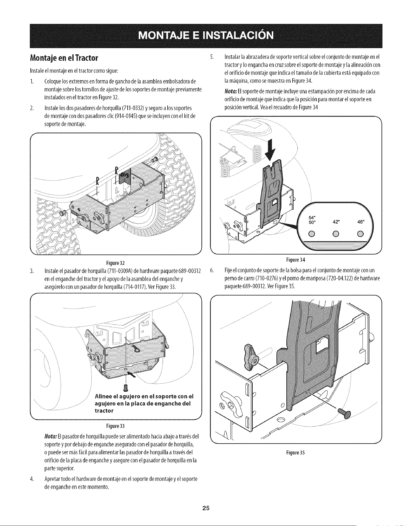
Montaje enel Tractor
Instaleel montajeeneltractorcomosigue:
1. Coloquelosextremosen formadeganchodela asambleaembolsadorade
montajesobrelostornillosde ajustedelossoportesdemontajepreviamente
instaladoseneltractoren Figure32.
2. Instalelosdospasadoresdehorquilla(711-0332)y seguroa lossoportes
demontajecondospasadoresclic(914-0145)queseincluyenconelkit de
soportede montaje.
Instalarlaabrazaderadesoporteverticalsobreel conjuntode montajeenel
tractoryIoenganchaencruzsobreel soportedemontajey laalineaci6ncon
elorificiodemontajequeindicael tamaffodela cubiertaest_equipadocon
la m_quina,comosemuestraen Figure34.
Nora: Elsoportede montajeincluyeunaestampaci6nporencimadecada
orificiode montajequeindicaquela posici6nparamontarelsoporteen
posici6nvertical.Veael recuadrodeFigure34
3.
Figure32
Instaleel pasadordehorquilla(711-0309A)dehardwarepaquete689-00312
enelenganchedeltractoryelapoyode laasambleadelenganchey
asegureloconun pasadorde horquilla(714-0117).VerFigure33.
/
\
/
/
j g
/ Alinee el agujero en el soporte con el
agujero en la placa de enganche del
tractor
Figure33
Nora:Elpasadorde horquiilapuedeseralimentadohaciaabajoatrav_sdel
soporteypordebajodeengancheaseguradoconel pasadordehorquilla,
opuedeserm_sf_cilparaalimentarlaspasadorde horquillaatray,s del
orificiodela piacadeenganchey asegureconelpasadorde horquillaen la
partesuperior.
4. Apretartodoelhardwarede montajeenelsoportedemontajey el soporte
deengancheenestemomento.
Figure34
Fijeelconjuntodesoportede la bolsaparaelconjuntodemontajeconun
pernodecarro(710-0276)y elpomode mariposa(720-04.122)de hardware
paquete689-00312.VetFigure35.
Figure35
25
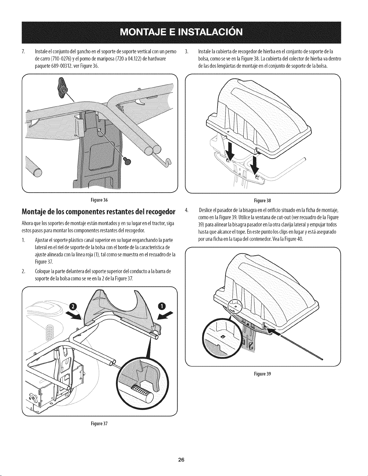
Instaleelconjuntodelganchoenelsoportede soporteverticalconun perno
decarro(710-0276)y elpomodemariposa(720a04.122)dehardware
paquete689-00312.verFigure36.
Instalelacubiertade recogedordehierbaenelconjuntodesoportedela
bolsa,comoseveen laFigure38. Lacubiertadelcolectordehierbavadentro
de lasdoslengiJetasdemontajeenelconjuntodesoportedelabolsa.
Figure36
Montajede ioscomponentes restantesdel recogedor 4.
Ahoraquelossoportesdemontajeest_inmontadosyen sulugaren eltractor,siga
estospasosparamontarloscomponentesrestantesdelrecogedor.
1. Ajustarel soportepl_isticocanalsuperioren sulugarenganchandolaparte
lateralenel rieldesoportedelabolsaconelbordedelacaracteristicade
ajustealineadaconlaI[nearoja(1),tal comosemuestraenel recuadrode la
Figure37.
2. Coloquelapartedelanteradelsoportesuperiordel conductoalabarrade
soportede labolsacomoseveenla2de la Figure37.
Figure38
Deslkeelpasadorde labisagraenelorificio situadoenla fichade montaje,
comoenla Figure39.Utilicela ventanadecut-out(vetrecuadrodela Figure
39)paraalinearla bisagrapasadorenlaotra clavijalateralyempujartodos
hastaquealcanceeltope.Enestepuntolosclipsenlugary est_asegurado
porunafichaen latapadelcontenedor.YealaFigure40.
Figure39
Figure37
26
f "_ 7.
Figure40
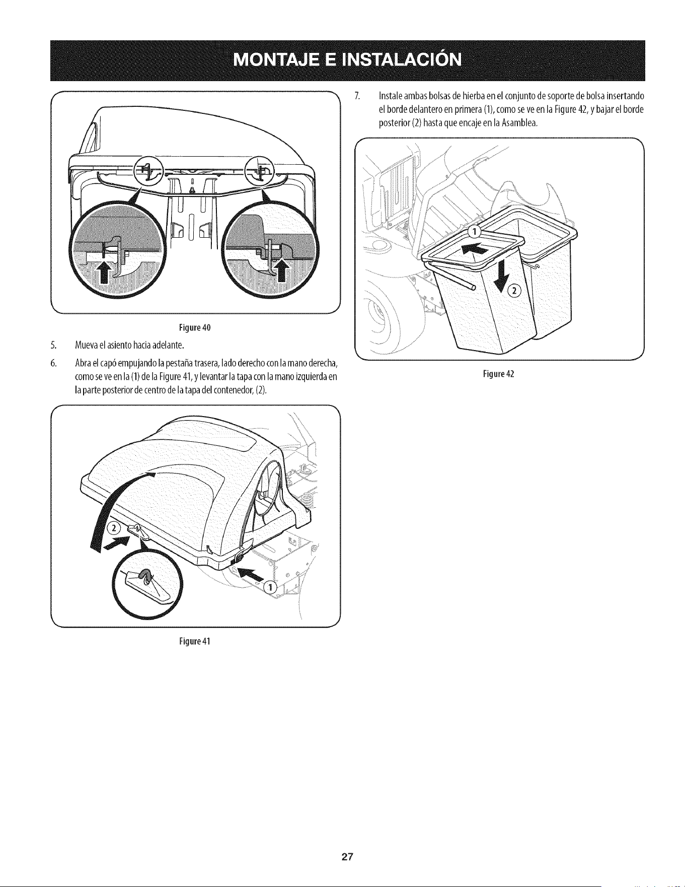
Muevaelaslentohadaadelante.
6,
Abraelcap6empujandolapestaffatrasera,ladoderechoconlamanoderecha,
comoseveenla (1)delaFigure41,y levantarlatapaconlamanoizquierdaen
laparteposteriordecentrodelatapadelcontenedor,(2).
Instaleambasbolsasdehierbaen elconjuntodesoportede bolsainsertando
el bordedelanteroen primera(1),comoseveenla Figure42,y bajarelborde
posterior(2)hastaqueencajeen laAsamblea.
Figure42
Figure41
27
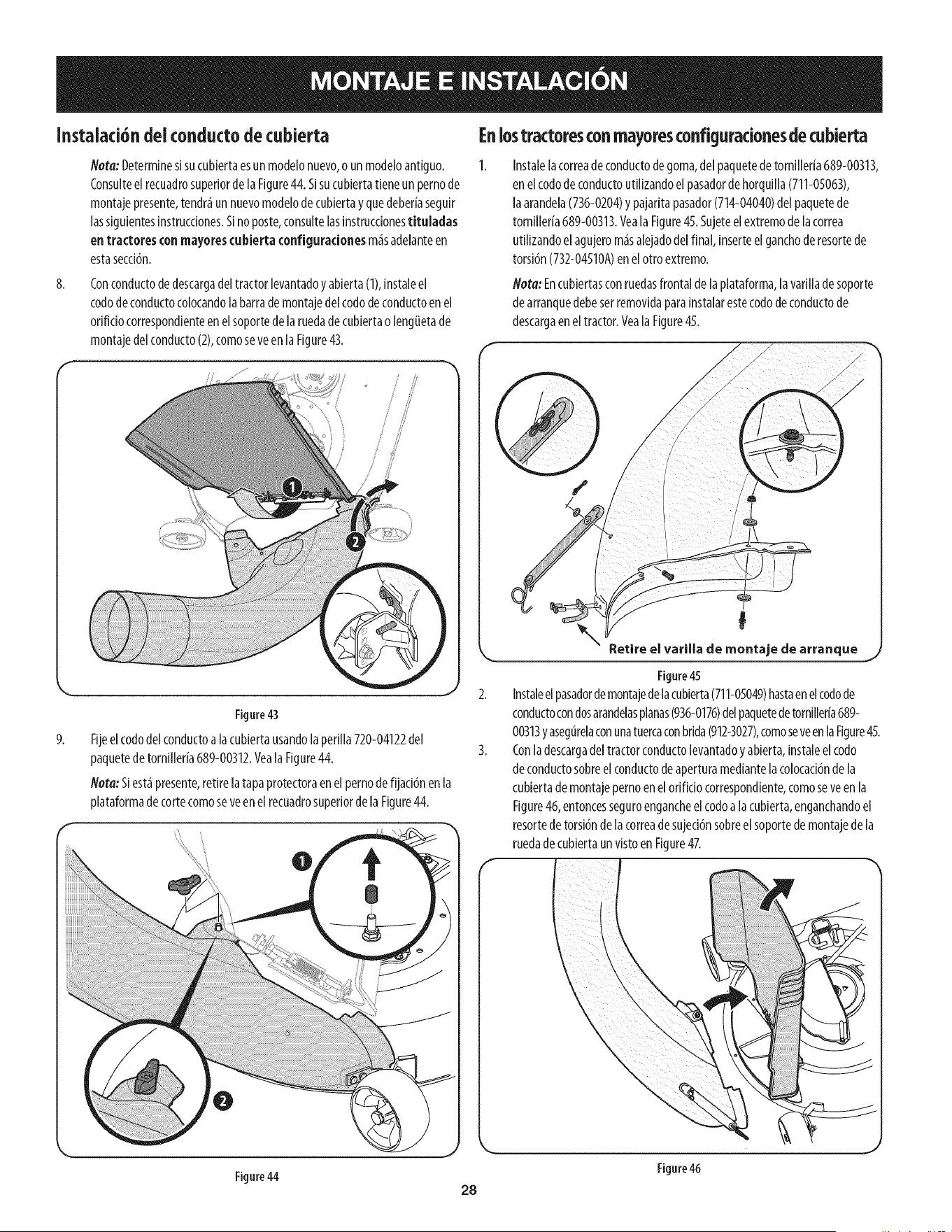
Instalaci6ndeiconductodecubierta
8.
Hera:Determinesisucubiertaesun modelonuevo,o un modeloantiguo.
Consulteelrecuadrosuperiorde laFigure44.Sisucubiertatieneunpernode
montajepresente,tendr_un nuevomodelode cubiertay quedeberiaseguir
lassiguientesinstrucciones.Sino poste,consultelasinstruccionestituladas
entractores conmayorescubiertaconfiguradonesm_sadelanteen
estasecci6n.
Conconductodedescargadeltractorlevantadoy abierta(1),instaleel
cododeconductocolocandolabarrademontajedelcododeconductoenel
orificiocorrespondienteenelsoportedela ruedade cubiertao lengiJetade
montajedelconducto(2),comoseveenla Figure43.
9.
Figure43
Fijeelcododelconductoa lacubiertausandolaperilla720-04122del
paquetedetornilleria689-00312.Veala Figure44.
Nota:Siest_presente,retire latapaprotectoraenel pernode fijaci6nenla
plataformadetortecomoseveenel recuadrosuperiorde laFigure44.
Enlostractoresconmayoresconfiguradonesdecubierta
Instalelacorreadeconductodegoma,delpaquetedetorniller[a689-00313,
en elcododeconductoutilizandoel pasadordehorquilla(711-05063),
laarandela(736-0204)y pajaritapasador(714-04040)del paquetede
tornilleria689-00313.Veala Figure45.Sujeteelextremode lacorrea
utilizandoel agujerom_salejadodelfinal, inserteelganchoderesortede
torsi6n(732-04510A)enelotroextremo.
Nora: Encubiertasconruedasfrontalde laplataforma,lavarillade soporte
dearranquedebeserremovidaparainstalarestecododeconductode
descargaeneltractor.Yeala Figure45.
I
Retire el varilla de montaje de arranque
Figure45
Instaleelpasadordemontajedelacubierta(711-05049)hastaenelcodode
conductocondosarandelasplanas(936-0176)delpaquetedetornilleria689-
00313y asegurelaconunatuercaconbrida(912-3027),comoseveenlaFigure45.
Conladescargadeltractorconductolevantadoyabierta,instaleel codo
deconductosobreel conductodeaperturamediantelacolocaci6ndela
cubiertademontajepernoenel orificiocorrespondiente,comoseveen la
Figure46, entoncesseguroengancheelcodoala cubierta,enganchandoel
resortedetorsi6nde lacorreadesujeci6nsobreel soportedemontajedela
ruedadecubiertaunvistoen Figure4Z
Figure46
Figure44
28
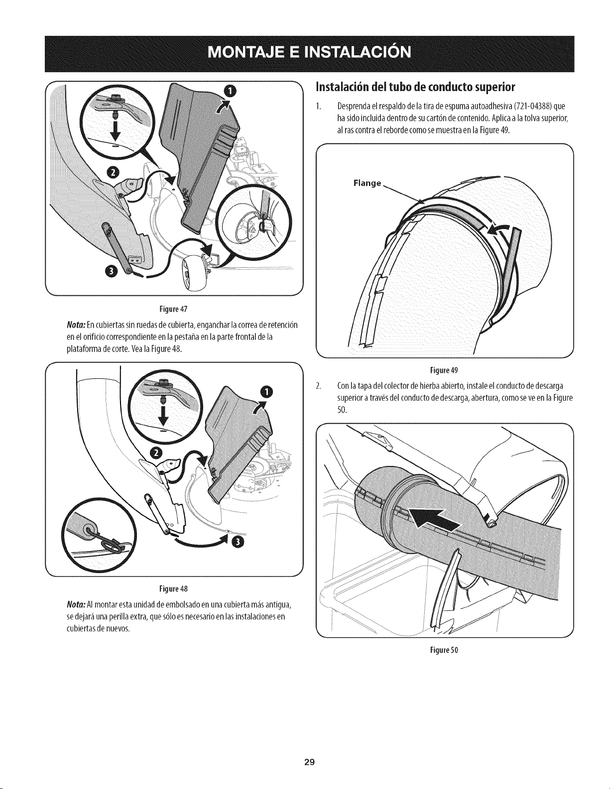
0 Instalad6ndei tubode conductosuperior
Figure47
Nora:Encubiertassin ruedasdecubierta,engancharlacorreaderetenci6n
enelorificiocorrespondienteen lapestaffaenla partefrontalde la
plataformadecorte.Veala Figure48.
Figure48
Nora:AImontarestaunidaddeembolsadoenunacubiertam_santigua,
sedejar_unaperiilaextra,ques61oesnecesarioenlasinstalacionesen
cubiertasde nuevos.
Desprendaelrespaldode latira deespumaautoadhesiva(721-04388)que
ha sidoincluidadentrodesucart6nde contenido.Aplicaa latolvasuperior,
al rascontraelrebordecomosemuestraen laFigure49.
Figure49
Conlatapadelcolectordehierbaabierto,instaleel conductodedescarga
superiora tray,s delconductodedescarga,abertura,comoseveen laFigure
50.
Figure50
29
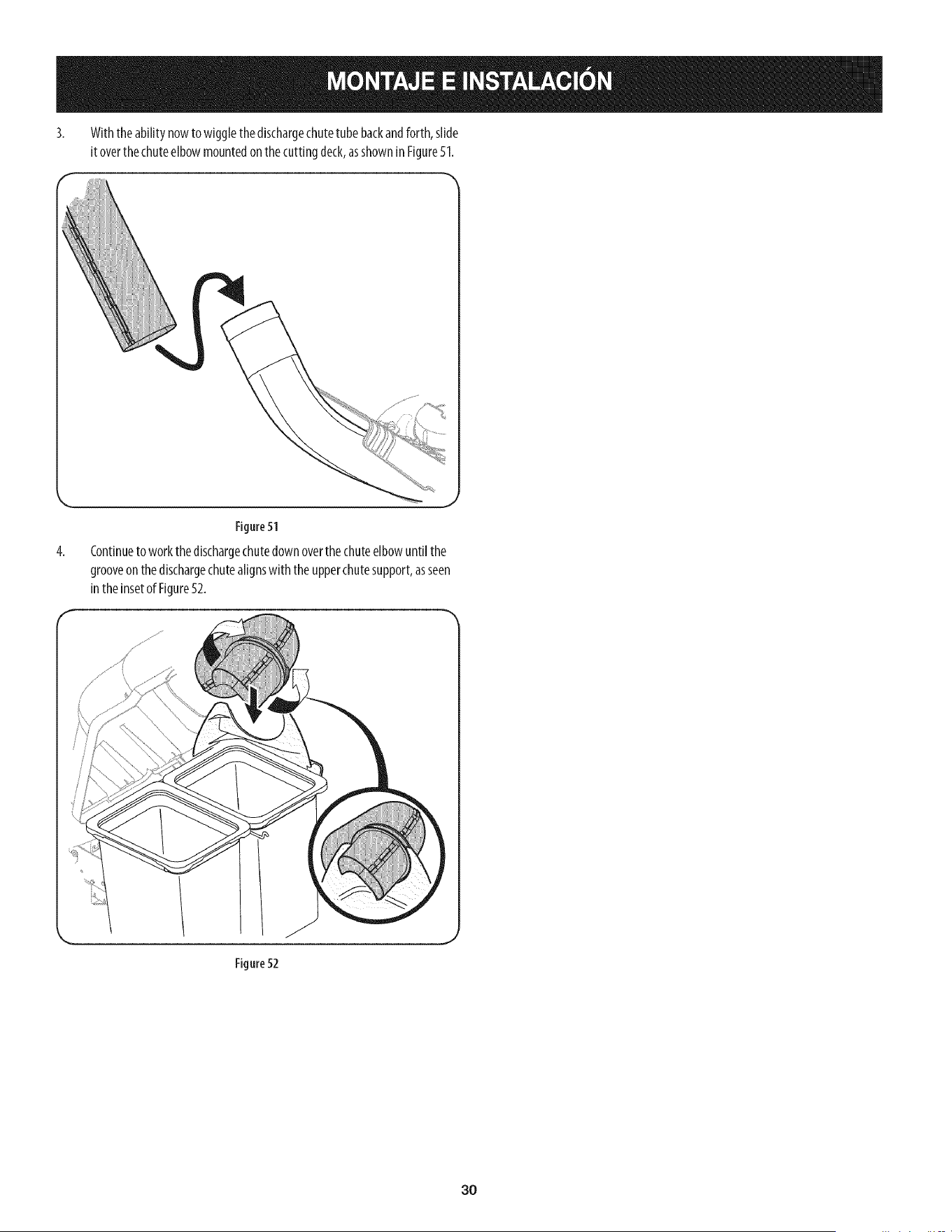
3. Withtheabilitynowtowigglethedischargechutetubebackandforth,slide
itoverthechuteelbowmountedonthecuttingdeck,asshowninFigure51.
4,
Figure51
Continueto workthe dischargechutedown overthe chuteelbowuntil the
grooveonthe dischargechutealignswith theupperchutesupport,asseen
intheinsetof Figure52.
Figure 52
30
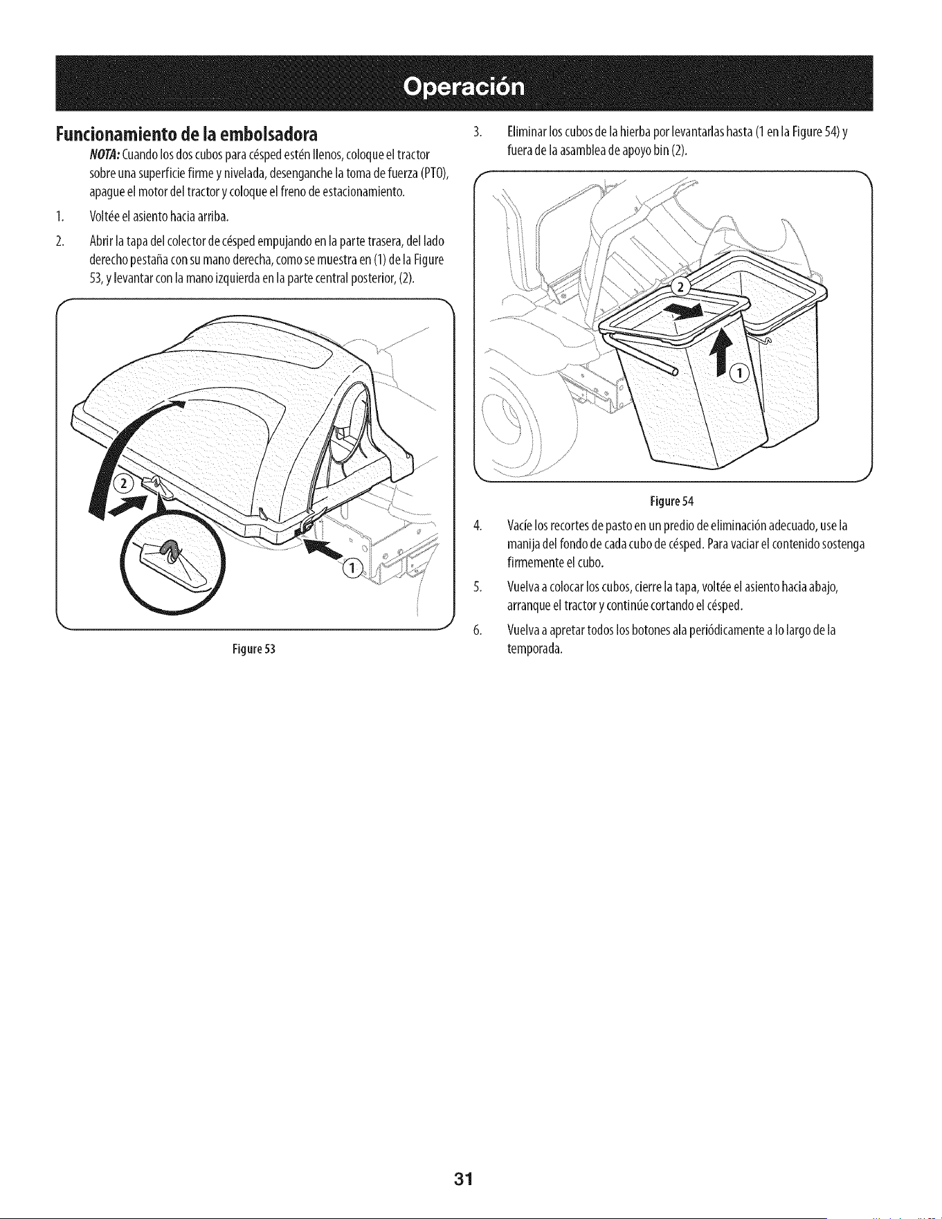
Fundonamiento de ia embolsadora
NOTA:Cuandolosdoscubosparac_spedest_nIlenos,coloqueeltractor
sobreunasuperfidefirmey nivelada,desenganchelatomade fuerza(PTO),
apagueel motordeltractory coloqueelfrenodeestadonamiento.
1. Volt_eelasientohadaarriba.
Abrirlatapadelcolectordec_spedempujandoenla partetrasera,dellado
derechopestafiaconsumanoderecha,comosemuestraen (1)de laFigure
53,ylevantarconlamanoizquierdaen lapartecentralposterior,(2).
Eliminarloscubosde laHerbaporlevantarlashasta(1enla Figure54)y
fueradelaasambleadeapoyobin(2).
Figure53
Figure54
Vacielosrecortesdepastoenun prediode eliminadbnadecuado,usela
manijadelrondodecadacubodec_sped.Pararadar elcontenidosostenga
firmementeel cubo.
5. Vuelvaacolocarloscubos,derrelatapa,volt_eel asientohadaabajo,
arranqueeltractorycontinuecortandoelc_sped.
6. Vuelvaaapretartodoslosbotonesalaperi6dicamentea Iolargodela
temporada.
31

This page intentionally left blank. Use this page to make any notes regarding your bagger.
32