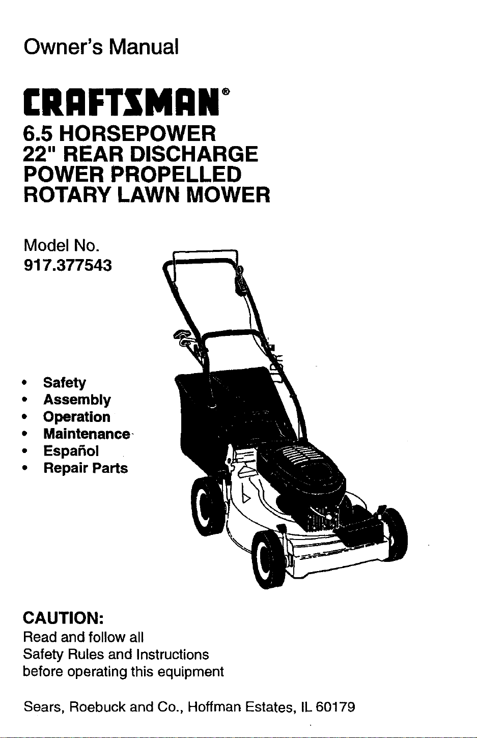
Owner's Manual
CRAFTS[MAN+
6.5 HORSEPOWER
22" REAR DISCHARGE
POWER PROPELLED
ROTARY LAWN MOWER
Model No.
917.377543
• Safety
• Assembly
• Operation
• Maintenance-
• EspaSol
• Repair Parts
CAUTION:
Read and follow all
Safety Rules and Instructions
before operating this equipment
Sears, Roebuck and Co., Hoffman Estates, IL 60179
Warranty 2 Product Specifications 11
Safety Rules 2 Service and Adjustments 14
Assembly 4 Storage 16
Operation 6 Troubleshooting 17
Maintenance Schedule 10 Repair Parts 37
Maintenance 10 Parts Ordering Back Cover
LIMITED TWO YEAR WARRANTY ON CRAFTSMAN POWER MOWER
For two years from date of purchase, when this Craftsman Lawn Mower is maintained,
lubricated, and tuned up according to the operating and maintenance instructions in the
owner's manual, Sears will repair free of charge any defect in material or workmanship.
If this Craftsman Lawn Mower is used for commercial or rental purposes, this warranty
applies for only 90 days from the date of purchase.
This Warranty does not cover:
• Expendable items which become worn during normal use, such as rotary mower
blades, blade adapters, belts, air cleaners and spark plug.
• Repairs necessary because of operator abuse or negligence, including bent crank-
shafts and the failure to maintain the equipment according to the instructions con-
tained in the owner's manual.
Warranty service is available by retuming the Craftsman power mower to the nearest
Sears Service Center/Department in the United States. This warranty applies only while
this product is in use in the United States.
This Warranty gives you specific legal rights, and you may also have other rights which
vary from state to state.
SEARS, ROEBUCK AND CO., D/817 WA, HOFFMAN ESTATES, ILLINOIS 60179
Safety standards require operator
presence controls to minimize the
risk of injury. Your unit is equipped
with such controls. Do not attempt to
defeat the function of the operator
presence controls under any
circumstances.
TRAINING:
• Read this operator's manual carefully.
Become familiar with the controls and
know how to operate your mower
properly. Leam how to quickly stop
mower.
• Do not allow children to useyour mower.
Never allow adults to use mower without
proper instructions.
• Keep the area of operation clear of all
persons, especially small children and
pets.
• Use mower only as the manufacturer
intended and as described in this manual.
• Do not operate mower if it has been
dropped or damaged in any manner.
Always have damage repaired before
using your mower.
• Do not use accessory attachments that
are not recommended by the manufac-
turer. Use of such attachments may be
hazardous.
• The blade turns when the engine is
running.
2
PREPARATION:
• Always thoroughly check the area to be
mowed and clear it of all stones, sticks,
wires, bones, and other foreign objects.
These objects will be thrown by the blade
and can cause severe injury.
• Always wear safety glasses or eye
shields when starting and while using
your mower.
• Dress properly. Do not operate mower
when barefoot or wearing open sandals.
Wear only solid shoes with good traction
when mowing.
• Check fuel tank before starting engine.
Do not fillgas tank indoors, when the
engine is running or when the engine is
hot. Allow the engine to cool for several
minutes before filling the gas tank. Clean
off any spilled gasoline before starting the
engine.
• Always make wheel height adjustments
before starting your mower. Never
attempt to do this while the engine is
running.
• Mow only in daylight or good artificial
light.
OPERATION:
• Keep your eyes and mind on your mower
and the area being cut. Do not let other
interests distract you.
• Do not mow wet or slippery grass. Never
run while operating your mower. Always
be sure of your footing -- keep a firm
hold on the handles and walk.
• Do not put hands or feet near or under
rotating parts. Keep clear of the discharge
opening at all times.
• Always stop the engine whenever you
leave or are not using your mower, or
before crossing driveways, walks, roads,
and any gravel---covered areas.
• Never direct discharge of matedal toward
bystanders nor allow anyone near the
mower while you are operating it.
• Before cleaning, inspecting, or repairing
your mower, stop the engine and make
absolutely sure the blade and all moving
parts have stopped. Then disconnect the
spark plug wire and keep itaway from the
spark plug to prevent accidental starting.
• Do not continue to run your mower ifyou
hit a foreign object. Follow the procedure
outlined above, then repa_ any damage
before restarting and operating you
mower.
• Do not change the governor settings or
overspeed the engine. Engine damage or
personal injury may result.
• Do not operate your mower ifit vibrates
abnormally. Excessive vibration is an
indication of damage; stop the engine,
safely check for the cause of vibration
and repair as required.
• Do not run the engine indoors. Exhaust
fumes are dangerous.
• Never cut grass by pullingthe mower
towards you. Mow across the face of
slopes, never up and down or you might
lose your footing. Do not mow exces-
sively steep slopes. Use caution when
operating the mower on uneven terrain
or when changing directions -- maintain
good footing.
• Never operate your mower without
proper guards, plates, grass catcher or
other safety devices in place.
MAINTENANCE AND STORAGE:
• Check the blade and the engine mount-
ing bolts often to be sure they are
tightened properly.
• Check all bolts, nuts and screws at
frequent intervals for proper tightness to
be sure mower is in safe working
condition.
• Keep all safety devices in place and
working.
• To reduce fire hazard, keep the engine
free of grass, leaves or excessive grease
and oil. -
• Check grass catcher often for deteriora-
tion and wear and replace worn bags.
Use only replacement bags that are
recommended by and comply with
specifications of the manufacturer of your
mower.
• Always keep a sharp blade on your
mower.
• Allow engine to cool before storing in any
enclosure.
• Never store mower with fuel in the tank
inside a building where fumes may reach
an open flame or an ignition source such
as a hot water heater, space heater,
clothes dryer, etc.
ACAUTION: Always disconnect spark
plug wire and place wire where itcannot
contact spark plug in order to prevent
accidental starting when setting up,
transporting, adjusting or making repairs.
WARNING
The engine exhaust from this product
contains chemicals known to the State of
California to cause cancer, birth defects,
or other reproductive harm.
3
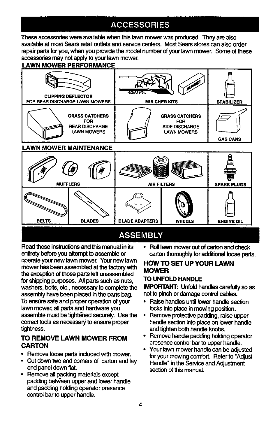
Theseaccessorieswereavailablewhenthislawnmowerwasproduced. They are also
available at mostSears retailoutletsand servicecanters. Most Sears stores can also order
repairparts foryou, when you providethe model number of yourlawn mower. Some of these
accessoriesmay notapply toyour lawn mower.
LAWN MOWER PERFORMANCE
CUPPING DEFLECTOR
FOR REAR DISCHARGE LAWN MOWERS
/_ GRASS CATCHERS
FOR
REAR DISCHARGE
LAWN MOWERS
MULCHERKITS
_! GRASS CATCHERS
FOR
SIDE DISCHARGE
LAWN MOWERS
STABILIZER
GAS CANS
LAWN MOWER MAINTENANCE
MUFFLERS
BELTS BLADES
AIR FILTERS
BLADE ADAPTERS WHEELS
SPARK PLUGS
ENGINE OIL
Read these instructionsand this manual in its
entiretybeforeyou attemptto assemble or
operateyour new lawn mower. Yournew lawn
mower has been assembled at thefactorywith
the exception ofthose parts leftunassemblad
for shippingpuq_oses. Allparts such as nuts,
washers, bolts,etc., necessary to complete the
assembly have been placed inthe parts hag.
To entre safe and properoperation ofyour
lawn mower,all parts and hardware you
assemble must be tightdnedsecurely. Use the
correcttools as necessary to ensure proper
tJghthess.
TO REMOVE LAWN MOWER FROM
CARTON
• Remove louseparts includedwith mower.
• Cut down two end comers of cartonand lay
end panel down flat.
• Remove all packing materials except
padding betv_een upper and lower handle
and padding holding operator presence
controlbar to upper handle.
4
• RolllawnmoweroutOfcartonandcheck
cartonthoroughlyforadditionallooseparts,
HOW TO SET UP YOUR LAWN
MOWER
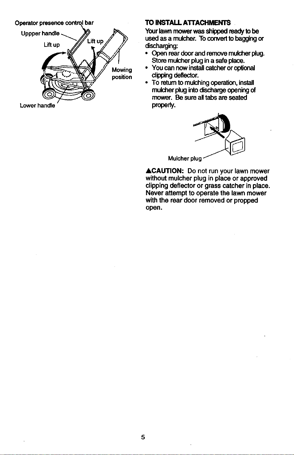
TO UNFOLD HANDLE
IMPORTANT: Unfoldhandlescarefullyso as
notto pinch or damage controlcables.
• Raise handles until lower handle section
locks into place in mowing position.
• Remove protective padding, raise upper
handle section into placa on lower handle
and tighten both handle knobs.
• Remove handle padding holding operator
presence control bar to upper handle.
• Your lawn mower handle can be adjusted
for your mowing comfort. Refer to "Adjust
Handle" in the Service and Adjustment
sec'donof this manual.
U
L.iftup
Lowerhandle
bar
Mowing
position
TO INSTALL A'n'ACHMENTS
Yourlawn mower was shipped ready to be
used as a mulcher. To convertto bagging or
discharging:
• Open rear door and remove mulcher plug.
Store mulcher plug ina safe place.
• You can now installcatcher or optional
dipping deflector.
• To retum to mulchingoperation,install
mulcher plug intodischarge opening of
mower. Be sure alltabs are seated
prope y.
Mulcher plug _
&CAUTION: Do not run your lawn mower
without mulcher plug in place or approved
clipping deflector or grass catcher in place.
Never attempt to operate the lawn mower
with the rear door removed or propped
open.
5
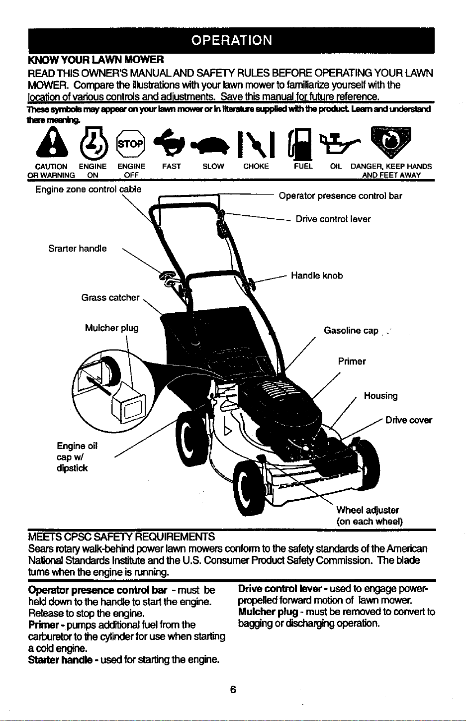
KNOWYOURLAWNMOWER
READ THIS OWNER'S MANUALAND SAFETY RULES BEFORE OPERATING YOUR LAWN
MOWER. Compare the illustrationswithyour lawn mower tofamiliarize yourself withthe
locationofvariouscontrolsand adiustmonts. Save this manualfor future reference.
_ symlx31smayappearonyourlawnrnowerorInIlteraUe=.,pldledwnhtheproduct.Lean a',,dunderstand
theren_g.
CAUTION ENGINE ENGINE FAST SLOW CHOKE FUEL OIL DANGER, KEEP HANDS
OR WARNING ON OFF AND FEET AWAY
Enginezonecontrolcable
Operatorpresencecontrolbar
Drive control lever
Srarter handle
Handleknob
Mulcherplug
Gasolinecap.."
Primer
Housing
Engineoil
capw/
dipstick
Wheel adjuster
(on eachwheel)
MEETS CPSC SAFETY REQUIREMENTS
Sears rotarywalk-behind power lawn mowers conformto the safetystandards oftheAmerican
National Standards Instituteand the U.S, Consumer ProductSafety Commission. The blade
turnswhen the engine isnJnning.
Operator presence control bar - must be
held downto the handle to startthe engine.
Release to stopthe engine.
Primer - pumps addlfJonalfuel from the
carburetorto the cylinderfor use when starling
a coldengine.
Starter handle - used for startingthe engine.
Drive control lever- used to engage power-
propelledforward motion of lawn mower.
Mulcher plug - mustbe removed to convert to
bagging or dischargingoperation.
6
The operation of any lawn mower can
result in foreign objects thrown into the
eyes, which can result in severe eye
damage. Always wear safety glasses or
eye shields while operating your lawn
mower or performing any adjustments or
repairs. We recommend a wide vision
safety mask over spectacles or standard
safety glasses.
HOW TO USE YOUR LAWN MOWER
ENGINE SPEED
The engine speed was set at the factory
for optimum performance. Speed is not
adjustable.
ENGINE ZONE CONTROL
ACAUTION: Federal regulations require
an engine control to be installed on this
lawn mower in order to minimize the risk of
blade contact injury. Do not under any
circumstances attempt to defeat the
function of the operator control. The blade
turns when the engine is running.
• Your lawn mower isequipped with an
operator presence controlbar which
reqdires the operator to be positioned
behind the lawn mower handle to start and
operate the lawn mower.
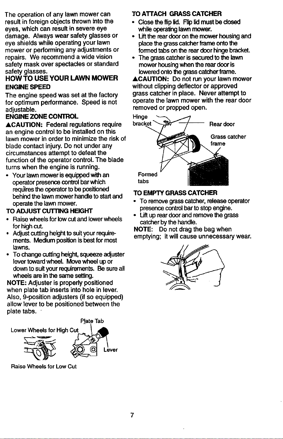
TO ADJUST cUTrlNG HEIGHT
• Raise wheels for low cut and lower wheels
for high cut.
• Adjust cutting height to suit your require-
ments. Medium posiUonis best for most
lawns.
• To change cuttingheight,squeeze adjuster
lover toward wheel.Move wheel up or
down to suityour requirements. Be sure all
wheels are inthe same setting.
NOTE: Adjustor is propedy positioned
when plate tab inserts into hole in lever.
Also, 9-position adjusters (if so equipped)
allow lever to be positioned between the
plate tabs.
Plate Tab
LowerWheels for High
Lever
Raise Wheels for LowCut
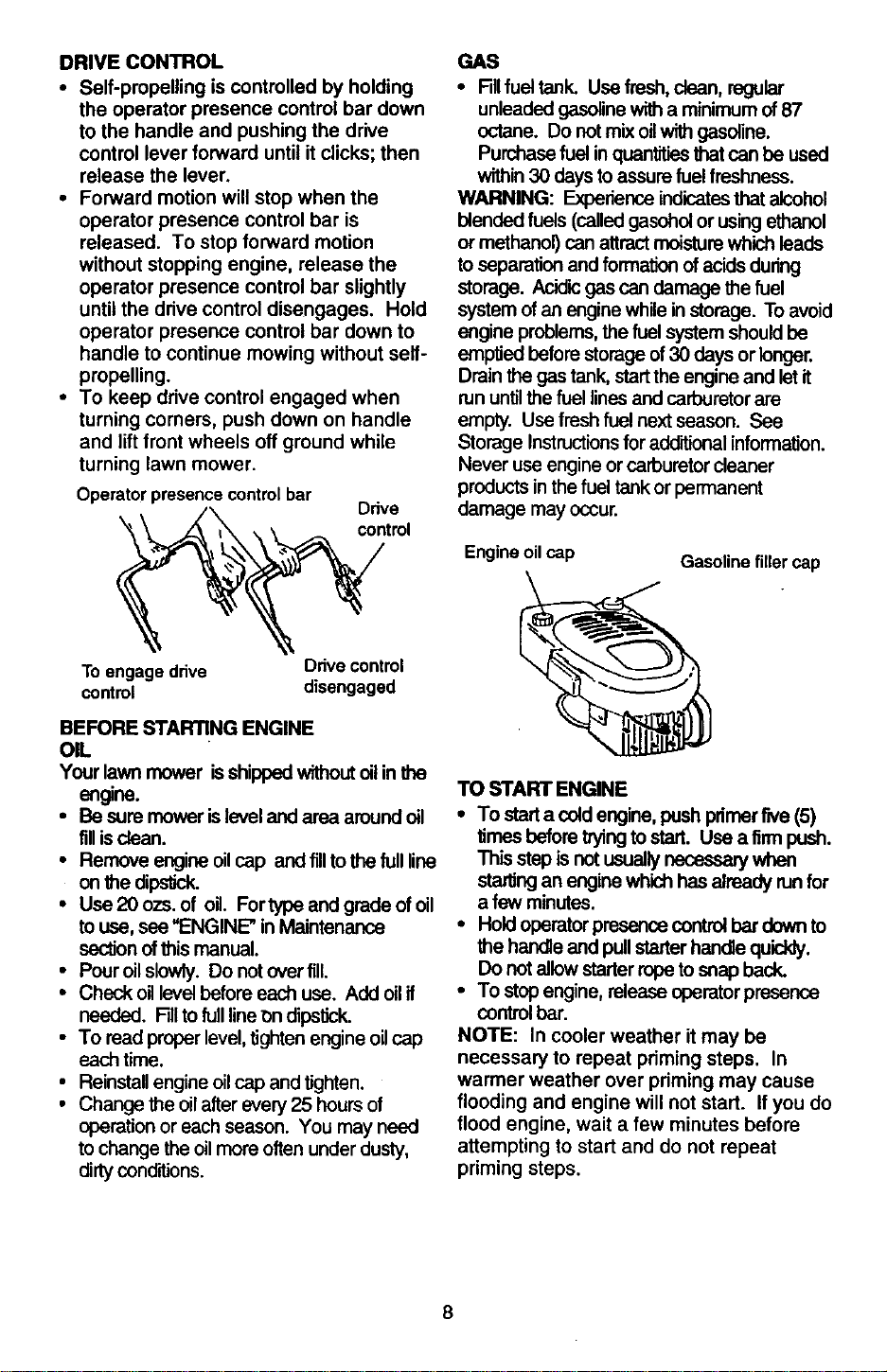
TO ATrACH GRASS CATCHER
• Close the fliplid. Rip lidmustbe dosed
while operaUnglawn mower.
• Liftthe reardoor on the mower housingand
place the grasscatcher frame ontothe
formed tabs onthe rear door hinge bracket.
• The grass catcher issecured to the lawn
mower housingwhen the rear door is
lowered ontothe grass catcher frame.
ACAUTION- Do not run your lawn mower
without clipping deflector or approved
grass catcher in place. Never attempt to
operate the lawn mower with the rear door
removed or propped open.
Hinge
Rear door
Grasscatcher
frame
Formed
tabs
TO EMPTY GRASS CATCHER
• To remove grass catcher, release operator
presence controlbar tostop engine.
• Uft up rear door and remove the grass
catcher by the handle.
NOTE: Do not drag the bag when
emptying; it will cause unnecessary wear.
7
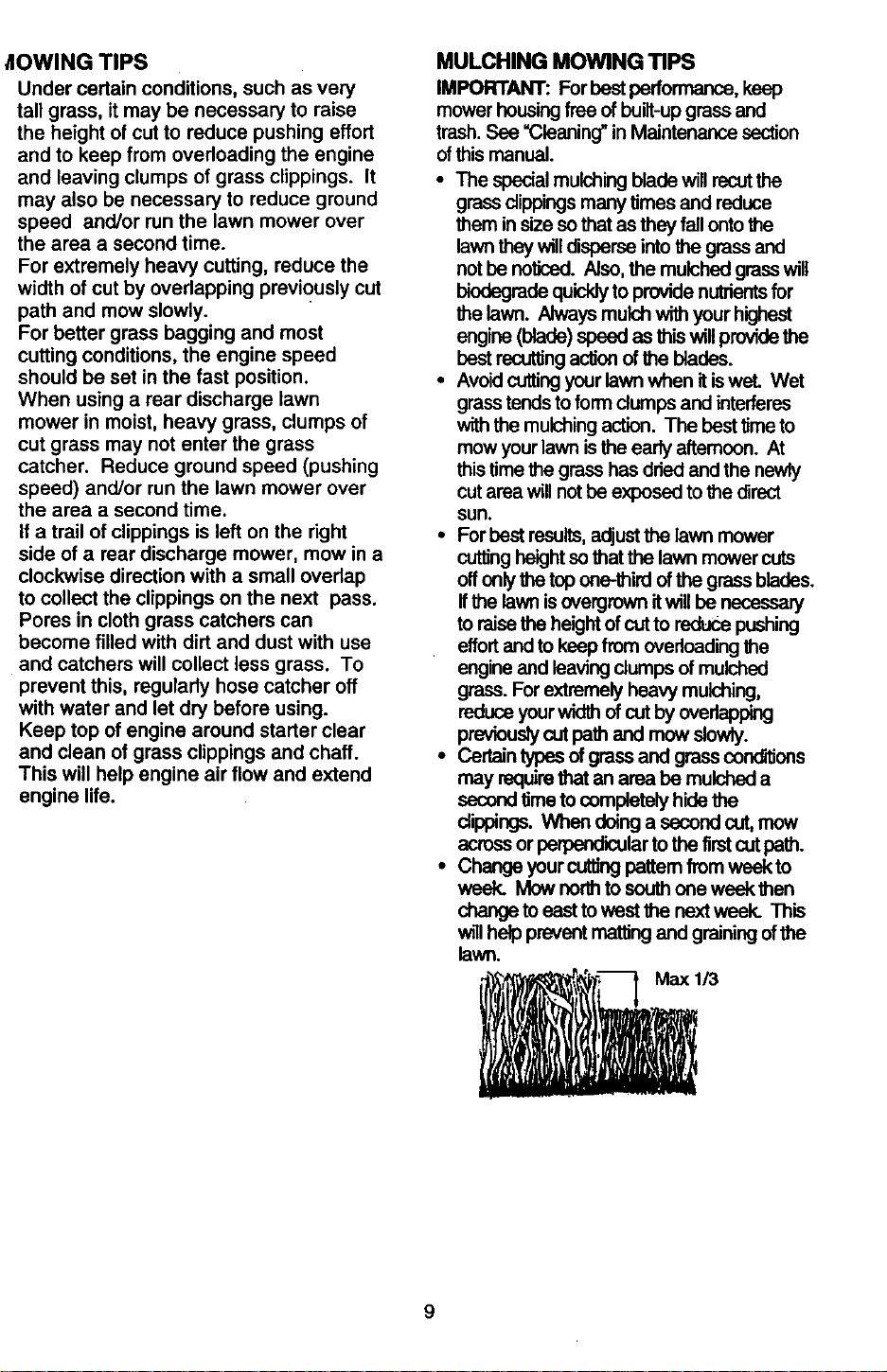
DRIVECONTROL
• Self-propellingiscontrolledbyholding
theoperatorpresencecontrolbardown
tothehandleandpushingthedrive
controlleverforward until itclicks; then
release the lever.
• Forward motion will stop when the
operator presence control bar is
released. To stop forward motion
without stopping engine, release the
operator presence control bar slightly
until the drive control disengages. Hold
operator presence control bar down to
handle to continue mowing without self-
propelling.
• To keep drive control engaged when
turning comers, push down on handle
and lift front wheels off ground while
turning lawn mower.
Operatorpresencecontrolbar
Ddve
"_ control
GAS
• RIIfuel tank. Use fresh,clean, regular
unleaded gasolinewitha minimum of87
octane. Do not mix oilwith gasoline.
Purchasefuel inquan'trtiesthatcan be used
within30 daysto assure fuel freshness.
WARNING: Experience indicatesthat alcohol
blended fuels (calledgasoholor using ethanol
or methanol) can attractmoisturewhich leads
to separation and formation ofacids during
storage. Acidicgas can damage thefuel
system of an engine while instorage. To avoid
engine problems,the fuelsystem shouldbe
emptied before storage of30 days or longer.
Drain the gas tank, startthe engine and let it
rununtilthe fuel lines and carburetorare
empty. Use fresh fuel nextseason. See
Storage Instructionsfor addRionalinformation.
Never use engine or carburetorcleaner
productsin the fuel tankor permanent
damage may occur.
Engineoilcap
Gasolinefillercap
To engagedrive Drivecontrol
control disengaged
BEFORE STARTING ENGINE
OIL
Your lawn mower isshippedwithoutoilin the
engiRe.
• Be sure mower islevel and area aroundoil
fillis ctean.
• Remove engine oilcap and fillto the full line
on the dipstick.
• Use 20 ozs. of oil. Fortype and grade of oil
touse, see "ENGINE" in Maintenance
ssction ofthis manual.
• Pouroil slowly. Do not overfill.
• Check oil level before each use. Add oilif
needed. Filltofulllineon dipstick.
• To read properlevel,tighten engine oilcap
each time.
• Reinstallengine oilcap and tighten.
• Change the oilafter every 25 hou_ of
operation or each season. You may need
to change the oilmore often under dusty,
dirtyconditions.
TO START ENGINE
• To stad a coldengine, push primerfive (5)
times beforetryingtostart. Use afirm push.
This step is not usually necessary when
startingan engine which has already runfor
a few minutes.
• Hold operatorpresence control bar down to
the handteand pullstarter handle quiddy.
Do not allowstarter ropeto snap beck.
• To stop engine, release operatorpresence
control bar.
NOTE: In cooler weather it may be
necessary to repeat priming steps. In
warmer weather over priming may cause
flooding and engine will not start. If you do
flood engine, wait a few minutes before
attempting to start and do not repeat
priming steps.
_IOWING TIPS
Under certain conditions, such as very
tall grass, itmay be necessary to raise
the height of cut to reduce pushing effort
and to keep from overloading the engine
and leaving clumps of grass clippings. It
may also be necessary to reduce ground
speed and/or run the lawn mower over
the area a second time.
For extremely heavy cutting, reduce the
width of cut by overlapping previously cut
path and mow slowly.
For better grass bagging and most
cutting conditions, the engine speed
should be set in the fast position.
When using a rear discharge lawn
mower in moist, heavy grass, clumps of
cut grass may not enter the grass
catcher, Reduce ground speed (pushing
speed) and/or run the lawn mower over
the area a second time.
If a trail of clippings is left on the right
side of a rear discharge mower, mow in a
clockwise direction with a small overlap
to collect the clippings on the next pass.
Pores in cloth grass catchers can
become filled with dirt and dust with use
and catchers will collect less grass. To
prevent this, regularly hose catcher off
with water and let dry before using.
Keep top of engine around starter clear
and clean of grass clippings and chaff.
This will help engine air flow and extend
engine life.
MULCHING MOWING TIPS
IMPORTANT: For bestparformance, keep
mower housingfree of built-upgrass and
trash. See =Cleaning" in Maintenance section
ofthis manual.
• The special mulching blade willrecut the
grass clippingsmany times and reduce
them in size so that as they fall ontothe
lawn they willdisperse into the grassand
not be noticed. Also, the mulched grass will
biodegrede quickly to provide nutrientsfor
the lawn. Always mulch with your highest
engine (blade)speed as this willprovidethe
best recurringa_on ofthe blades.
•Avotd cuttingyour lawn when itiswet. Wet
grass tends toform dumps and interferes
with the mulchingaction. The best timeto
mow yourlawn isthe early afternoon. At
this time the grass has dried and the newly
cut area willnot be exposed to the direct
sun.
• Forbest results,adjustthe lawn mower
cuttingheightso that the lawn mower cuts
offonlythe top one-third ofthe grass blades.
Ifthe lawn isovergrown itwill be necessary
to raise the heightof cutto reduce pushing
effortand to keepfrom overloading the
engine and leaving clumps of mulched
grass. For extremely heavy mulching,
reduce your wicl_ of cut byoverlapping
previouslycutpath and mow slowly.
• Certain typesof grass and grass conddions
may requirethat an area be mulched a
secondtimeto completely hide the
clippings. When doinga second cut,mow
acrossor perpendicularto the firstcutpath.
• Change yourcuttingpatternfrom week to
week. Mow nodh to southone week then
change toeast towest the nextweek. This
will help prevent matting and grainingof the
lawn.
/3
9
MAINTENANCESCHEDULE i_ ,_._ _ _,O_'_/'I"
REGULARSERVICE /_" _O?,_,_.-_ SERVICE nDATES
mill /_
Check for Loose Fasteners I/ If
Clean/Inspect Grass Catcher
(if Equipped) _'/ !_ i 1/
M clean,-weMower _ If
W_ CleanUnderDriveCover
(Power-Propalled Mowers) I,/
Checkdrivebelt/pulleys
RE (powe r-PropelledMowers)
Check/Sharpen/Replace Blade 1/3
Lubrication Chart I,/ I_
Cleon Battery/Recharge
IElectric Start Mowers I If I/4
E Check Engine Oil Level 1/
N Change Engine Oil 1/1.2
G Clean Air Filter 1/z
i Inspect Muffler
N Clean or Replace Spark Plug
E Replace Air Filter Paper Carlddge 1/2
1- Change morn_ wh4moperating under = heavy load or in high ambienttemperaturN.
2 - S_'V_e more oflml when operaling kld_ or du_y condi¢oe=.
3 - I_place Idadee more oaen when mowing ia=umd,/=all
4 - Charge 48 hoursat m)d of SellOn,
GENERAL RECOMMENDATIONS
The warranty on this lawn mower does not
cover items that have been subjected to
operator abuse or negligence. To receive
full value from the warranty, operator must
maintain mower as instructed in this
manual.
Some adjustments will need to be made
periodically to properly maintain your unit.
All adjustments in the Service and
Adjustments section of this manual should
be checked at least once each season.
• Once a year, replace the spark plug,
replace air filter element and check
blade for wear. A new spark plug and
clean/new air filter element assures
proper air-fuel mixture and helps your
engine run better and last longer.
• Follow the maintenance schedule in this
manual.
BEFORE EACH USE
• Check engine oil level.
• Check for loose fasteners.
LUBRICATION
Keep unit well lubricated (See "LUBRICA-
TION CHART").
10
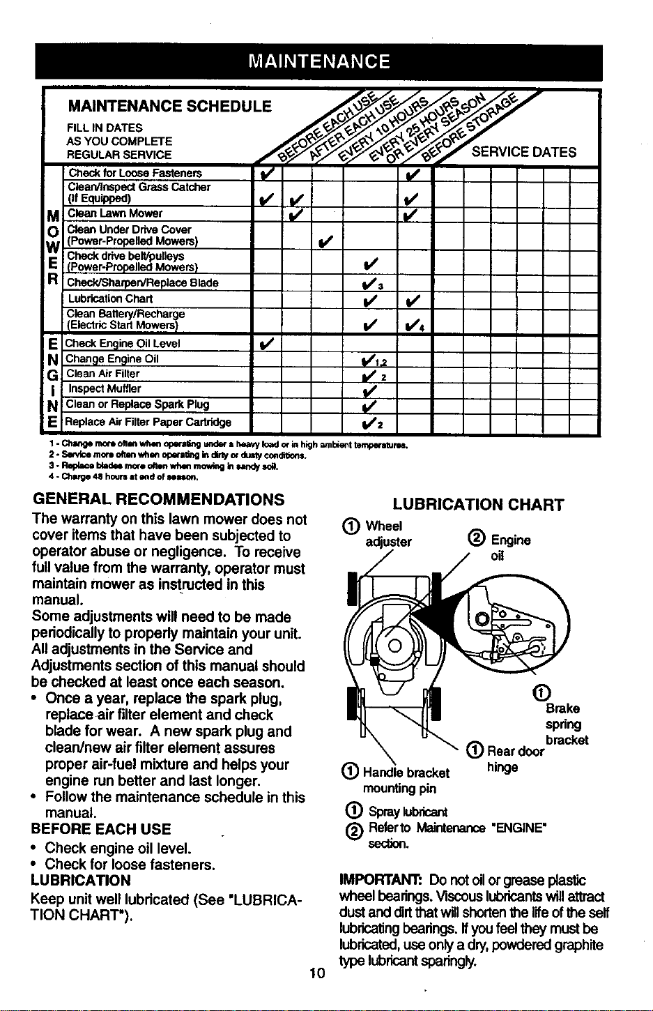
LUBRICATION CHART
(_) Wheel
adjuster (_) Engine
oil
(_ Handlebracket
mountingpin
® Spray
Brake
spring
_) Rear door bra_et
hinge
(_ Referto Maintenance"ENGINE"
section.
IMPORTANT: Do not oilor grease plastic
wheel bearings. Viscouslubricantswillattract
dust and dirtthatwillshortenthe lifeofthe self
lubricatingbearings. Ifyou feelthey must be
lubricated,use only a dry,powdered graphite
type lubricantsparingly.
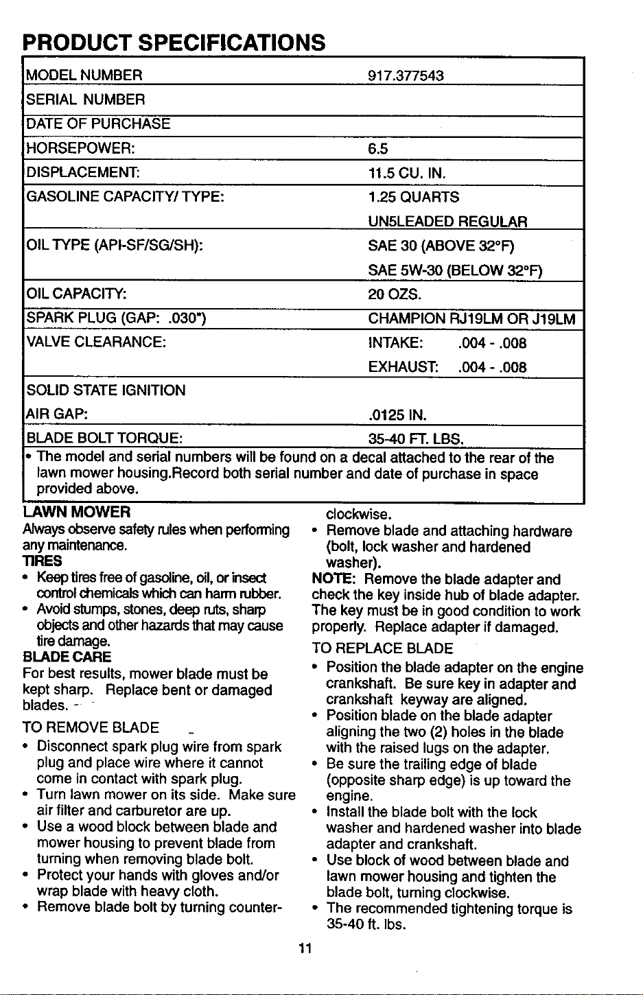
PRODUCT SPECIFICATIONS
MODEL NUMBER 917.377543
;ERIAL NUMBER
DATE OF PURCHASE
HORSEPOWER: 6.5
DISPLACEMENT: 11.5 CU. IN.
GASOLINE CAPACITY/TYPE: 1.25 QUARTS
UN5LEADED REGULAR
OIL TYPE (API-SF/SG/SH): SAE 30 (ABOVE 32°F)
SAE 5W-30 (BELOW 32°F)
OIL CAPACITY: 20 OZS.
SPARK PLUG (GAP: .030") CHAMPION RJ19LM OR J19LM
VALVE CLEARANCE: INTAKE: .004 - .008
EXHAUST: .004 - .008
SOLID STATE IGNITION
AIR GAP: .0125 IN.
BLADE BOLT TORQUE: 35-40 FT. LBS.
The model and sedal numbers will be found on a decal attached to the rear of the
lawn mower housing.Record both serial number and date of purchase in space
provided above.
LAWN MOWER
Always observe safety ruleswhen performing
any maintenance.
TIRES
• Keep tiresfree of gasoline, oil, or insect
controlchemicalswhich can harm rubber.
• Avoid stumps,stones,deep ruts,sharp
objectsand otherhazards that may cause
tire damage.
BLADE CARE
For best results, mower blade must be
kept sharp. Replace bent or damaged
blades. -
TO REMOVE BLADE
• Disconnect spark plug wire from spark
plug and place wire where it cannot
come in contact with spark plug.
• Turn lawn mower on its side. Make sure
air filter and carburetor are up.
• Use a wood block between blade and
mower housing to prevent blade from
turning when removing blade bolt.
• Protect your hands with gloves and/or
wrap blade with heavy cloth.
• Remove blade bolt by turning counter-
clockwise.
• Remove blade and attaching hardware
(bolt, lock washer and hardened
washer).
NOTE: Remove the blade adapter and
check the key inside hub of blade adapter.
The key must be in good condition to work
properly. Replace adapter if damaged.
TO REPLACE BLADE
• Position the blade adapter on the engine
crankshaft. Be sure key in adapter and
crankshaft keyway are aligned.
• Position blade on the blade adapter
aligning the two (2) holes in the blade
with the raised lugs on the adapter.
• Be sure the trailing edge of blade
(opposite sharp edge) is up toward the
engine.
• Install the blade bolt with the lock
washer and hardened washer into blade
adapter and crankshaft.
• Use block of wood between blade and
lawn mower housing and tighten the
blade bolt, turning clockwise.
• The recommended tightening torque is
35-40 ft. Ibs.
11
IMPORTANT: Blade bolt is grade 8 heat
treated.
TO SHARPEN BLADE
NOTE: We do not recommend sharpening
blade - but if you do, be sure the blade is
balanced.
Care should be taken to keep the blade
balanced. An unbalanced blade will cause
eventual damage to lawn mower or
engine.
• The blade can be sharpened with a file
or on a grinding wheel. Do not attempt
to sharpen while on the mower.
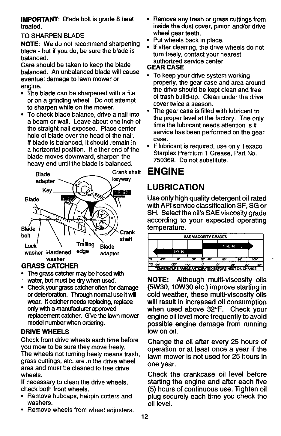
• To check blade balance, drive a nail into
a beam or wall. Leave about one inch of
the straight nail exposed. Place center
hole of blade over the head of the nail.
If blade is balanced, it should remain in
a horizontal position. If either end of the
blade moves downward, sharpen the
heavy end until the blade is balanced.
Blade Crankshaft
keyway
Blade
bolt
shaft
Lock Blade
washer Hardened edge adapter
washer
GRASS CATCHER
• The grass catcher may be hosed with
water, but mustbe dry when used.
• Check your grass catcher oftenfor damage
or deterioraUon. Through normal use itwill
wear. Ifcatcher needs replacing,replace
onlywith a manufacturerapproved
replacement catcher. Give the lawn mower
model number when ordering.
DRIVE WHEELS
Check front drive wheels each time before
you mow to be sure they move freely.
The wheels not turning freely means trash,
grass cuttings, etc. are in the drive wheel
area and must be cleaned to free drive
wheels.
If necessary to clean the drive wheels,
check both fro_t wheels.
• Remove hubcaps, hairpin cotters and
washers.
• Remove wheels from wheel adjusters.
• Remove any trash or grass cuttings from
inside the dust cover, pinion and/or drive
wheel gear teeth.
• Put wheels back in place.
• If after cleaning, the drive wheels do not
turn freely, contact your nearest
authorized service center.
GEAR CASE
• To keep your drive system working
properly, the gear case and area around
the drive should be kept clean and free
of trash build-up. Clean under the drive
cover twice a season.
• The gear case is filled with lubricant to
the proper level at the factory. The only
time the lubricant needs attention is if
service has been performed on the gear
case.
• If lubricant is required, use only Texaco
Starplex Premium 1 Grease, Part No.
750369. Do not substitute.
ENGINE
LUBRICATION
Use only high quality detergent oil rated
with API service classification SF, SG or
SH. Select the oil's SAE viscosity grade
according to your expected operating
temperature.
NOTE: Although multi-viscosity oils
(5W30, 10W30 etc.) improve starting in
cold weather, these multi-viscosity 0ils
will result in increased oil consumption
when used above 32°F. Check your
engine oil level more frequently to avoid
possible engine damage from running
low on oil.
Change the oil after every 25 hours of
operation or at least once a year if the
lawn mower is not used for 25 hours in
one year,
Check the crankcase oil level before
starting the engine and after each five
(5) hours of continuous use. Tighten oil
plug securely each time you check the
oil level.
12
TOCHANGEENGINEOIL
NOTE:Beforetippinglawnmowertodrain
oil,drainfuel tank by running engine until
fuel tank is empty.
• Disconnectspark plugwire from spark plug
and place wire where itcannot come in
contact with spark plug.
• Remove engine oilcap; lay aside on a dean
surface.
• T'_olawn mower on itsside as shown and
drain oilintoa suitable container. Rock lawn
mower back and forth to remove any oil
t_ insideof engine.
• W'_oeoffany spilledoilon lawn mower and
on side of engine.
• Fillengine with oil. Fillonlyto the =FULL"
lineon the dipstick. DO NOT overfill.
• Replace engine oilcap.
• Reconnect spark plug wire to spark plug.
Container
AIR FILTER
Your engine will not run properly and may
be damaged by using a dirty air filter.
Replace the air filter every year, more
often if you mow in very dusty, dirty
conditions. Do not wash air filter.
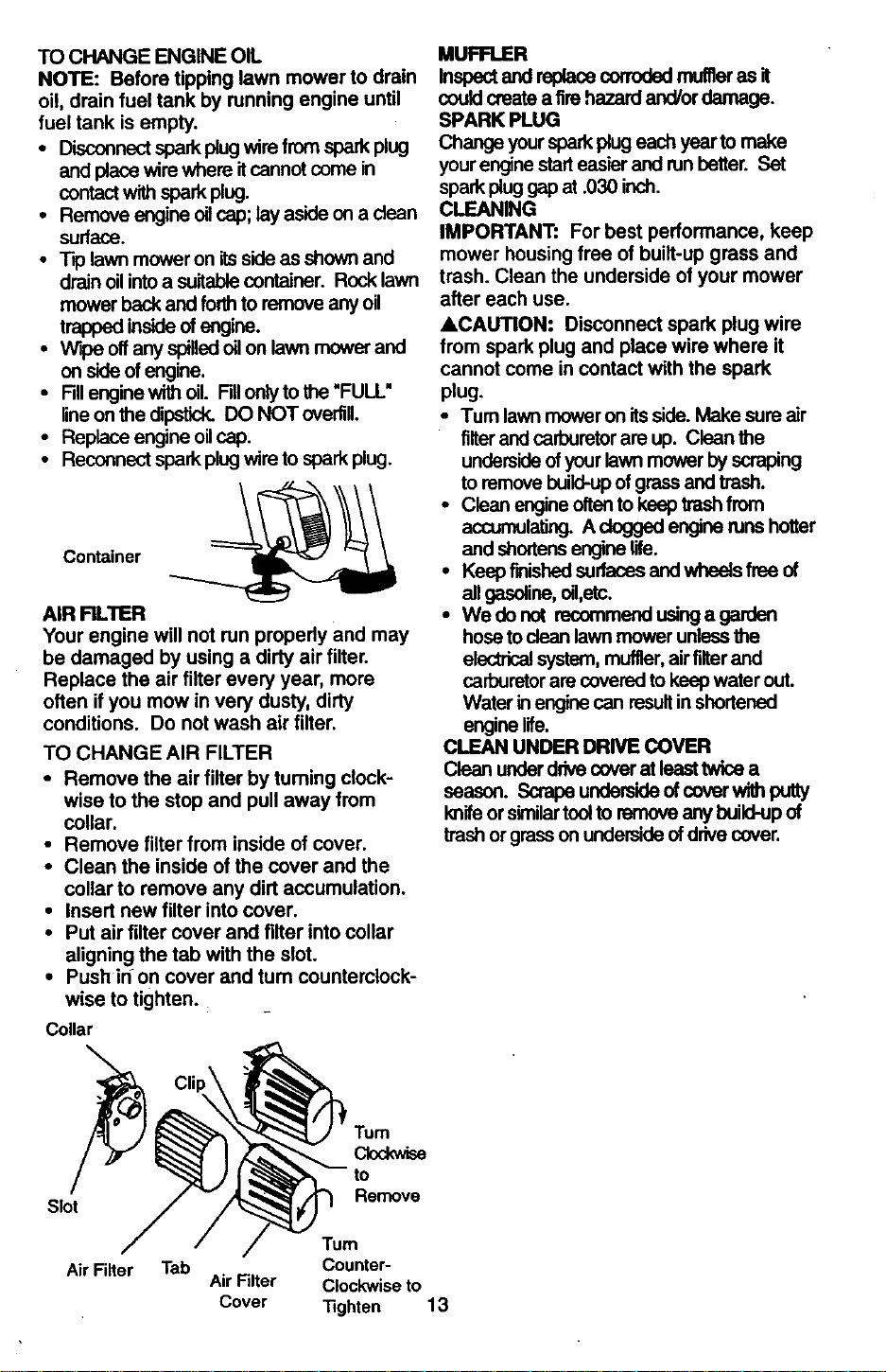
TO CHANGE AIR FILTER
• Remove the air filter by tuming clock-
wise to the stop and pull away from
collar.
• Remove filter from inside of cover.
• Clean the inside of the cover and the
collar to remove any dirt accumulation.
• Insert new filter into cover.
• Put air filter cover and filter into collar
aligning the tab with the slot.
• Push in on cover and tum counterclock-
wise to tighten.
Collar
MUFFLER
Inspectand replacecorroded muffleras it
couldcreate a fire hazard and/or damage.
SPARK PLUG
Change your sparkplug each yearto make
yourengine starteas'_r and runbetter. Set
spark plug gap at .030 inch.
CLEANING
IMPORTANT: For best performance, keep
mower housing free of built-up grass and
trash. Clean the underside of your mower
after each use.
ACAUTION: Disconnect spark plug wire
from spark plug and place wire where it
cannot come in contact with the spark
plug.
•Tum lawn mower on itsside.Make sure air
filterand carburetorare up. Clean the
undersideofyourlawnmower by scraping
toremove build-upofgrassand trash.
• Clean engine oftento keep trash from
accumulating. A dogged engine runshotter
and shortens engine life.
• Keep finishedsurfacas and wheels free of
all gasoline, oil,etc.
• Wedonot recommend usinga garden
hose toclean lawn mower unlessthe
electricalsystem, muffler,air filterand
carburetor are coveredto keep water out.
Water in engine can resultinshortened
engine life.
CLEAN UNDER DRIVE COVER
Clean underddve cover at leasttwlee a
season. Scrapa underside ofcover with putty
I_ife or similartoolto remove any build-upof
trash or grasson underside ofdrive cover.
Slot
Air Filter
Remove
"rum
Tab Counter-
Air Filter Clockwise to
Cover Tighten 13
ACAUTION: Before performing any
service and adjustments:
• Release control bar and stop engine.
• Make sure the blade and all moving
parts have completely stopped.
• Disconnect spark plug wire from spark
plug and place where it cannot come
in contact with plug.
LAWN MOWER
TO ADJUST CUTTING HEIGHT
See "TO ADJUST CUTTING HEIGHT" inthe
Operation sectionof this manual.
REAR DEFLECTOR
The rear deflector, attached between the rear
wheels ofyourlawn mower, is providedto
minimize the possibilitythatobjectswillbe
thrown out the rear ofthe lawn mower intothe
operator'smowing position, ffthe rear
deflectorbecomes d_na_d, it shouldbe
replaced.
TO REMOVE/REPLACE DRIVE BELT
• Remove drivecover. Remove belt by
pushing downon gear case pulleyand roll
belt off.
• Tum lawn mower on itsside with carburetor
and fuel cep up.
• Remove blade.
• Remove debris shield.
• Remove belt from engine pulley on
crankshaft.
• Installnew belt by reversingabove stepe.
• Always use factoryapproved beltto assure
and Ufe.
• Remove the starterrope guidefrom the
upper handle.
• Remove hairpincotters.
• Disconnectthe lower handle from the
handle brackets.
• Turn the handle over and reassemble the
hairpin cotters that have been removed.
• Reassemble the starter ropeguide.
• Reassemble the controls and the operator
presence controlbar to _ upper handle.
ACAUTION: The operator presence
control bar must pivot freely to permit
blade brake engagement when control bar
is released. Do not over tighten the
fasteners holding the controls to the upper
handle.
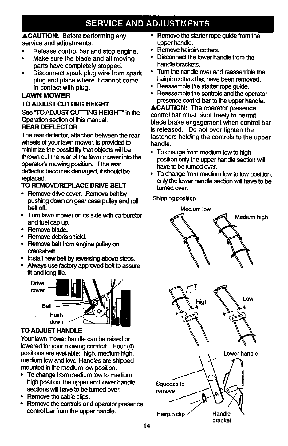
• To change from medium low to high
positiononly the upper handle section will
have to be tumed over.
• To change from medium towto lew posi_on,
only the lower handle sectionwill have to be
turned over.
Shippit_jposition
Mediumlow
high
Dd::rBe_ _High _ow
TOouAaDJwnUmSTowH,rND_ie_canbe raisedor Y__ _"__
lowered foryour mowing comfort. Four (4)
positionsare available: high,medium high,
medium lowand low. Handles are shipped
mounted inthe medium lowpos'_ion.
• To changefrom medium low to medium
high position, the upper and lower handle
sectionswill have to be tumed over.
• Remove the cable dips.
• Remove the controlsand operator presence
control bar from the upper handle.
14
Lower handle
Squeeze to _
bracket
ENGINE SPEED
Your engine speed has been factory set.
Do not attempt to increase engine speed
or it may result in personal injury. If you
believe that the engine is running too fast
or too slow, take your lawn mower to an
authorized service center for repair and
adjustment.
CARBURETOR
Your carburetor has a non-adjustable fixed
main jet for mixture control. If your engine
does not operate propedy due to sus-
pected carburetor problems, take your
lawn mower to an authorized service
center for repair and/or adjustment.
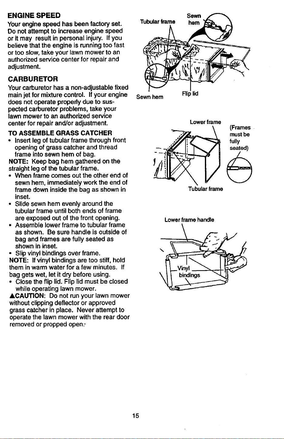
TO ASSEMBLE GRASS CATCHER
• Insert leg of tubular frame through front
opening of grass catcher and thread
frame into sewn hem of bag.
NOTE: Keep bag hem gathered on the
straight leg of the tubular frame.
• When frame comes out the other end of
sewn hem, immediately work the end of
frame down inside the bag as shown in
inset.
• Slide sewn hem evenly around the
tubular frame until both ends of frame
are exposed out of the front opening.
• Assemble lower frame to tubular frame
as shown. Be sure handle is outside of
bag and frames are fully seated as
shown in inset.
• Slip vinyl bindings over frame.
NOTE: If vinyl bindings are too stiff, hold
them in warm water for a few minutes. If
bag gets wet, let it dry before using.
• Close the flip lid. Flip lid must be closed
while operating lawn mower.
ACAUTION: Do not run your lawn mower
without clipping deflector or approved
grass catcher in place. Never attempt to
operate the lawn mower with the rear door
removed or propped open:
Sewn
Tubular frame hem
Sewn hem Rip lid
Lowerframe
Tubularframe
Lowerframehandle
\ Vinyl "_
(Frames
mustbe
fully
seated)
15
Immediately prepare your lawn mower for
storage at the end of the season or ifthe unit
willnot be used for 30 days or more.
LAWN MOWER
When lawn mower isto be storedfor a period
of time, clean itthoroughly,remove all dirt,
grease, leaves, eto. Store in a dean, dry area.
• Clean entirelawn mower (See "CLEANING"
inthe Maintenance section ofthismanual).
• Lubricateas shown inthe Maintenance
sectionofthis manual.
• Be sure thatall nuts,bolts,screws, and pins
are securelyfastened. Inspect moving
parts for damage, breakage and wear
Replace if necessary.
• Touch up all rustedor chippedpaint
surfaces; sand lightlybefore painting
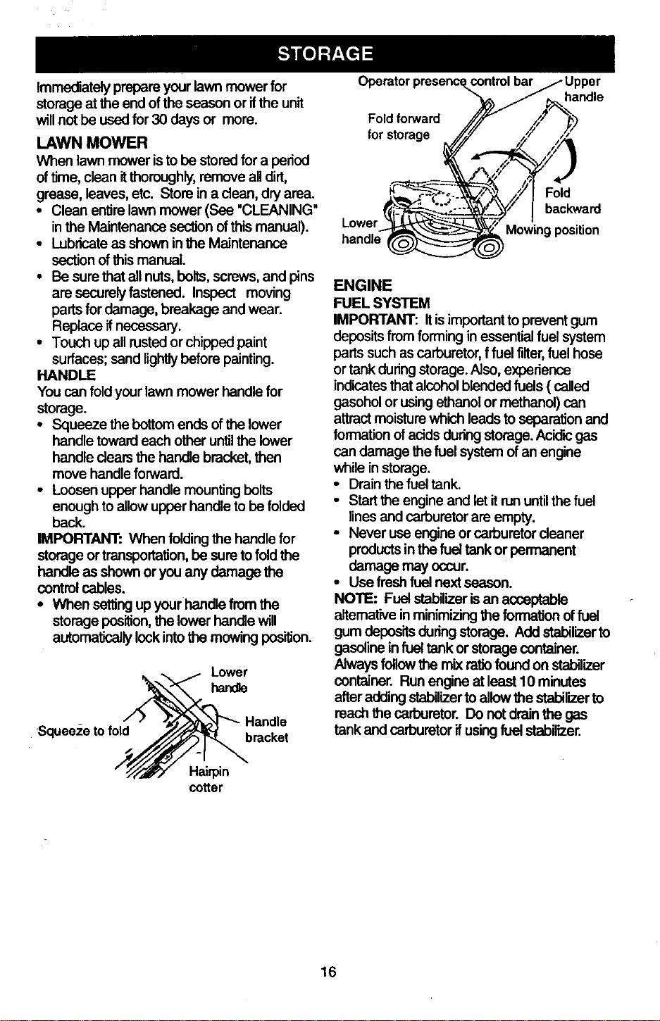
HANDLE
You can fold yourlawn mower handle for
storage.
• Squeeze the bottom ends ofthe lower
handle toward each other untilthe lower
handle dears the handle bracket, then
move handle forward.
• Loosen upper handle mountingbolts
enough to allowupper handle to be folded
beck
IMPORTANT: When foldingthe handle for
storage or transportation,be sure to foldthe
handle as shown oryou any damage the
controlcables.
• When settingup yourhandle from the
storageposition,the lower handle will
automaticallylockintothe mowing position
Squeeze to fold
Handle
bracket
Hai@n
cotter
control bar / Upper
Operatorpresence.__/ . handle
Fold forward //.//_ ,('_" _,_
I backward
..... %\_--_," l
Lower_ Mov_ingposition
handle
ENGINE
FUEL SYSTEM
IMPORTANT: Itisimportanttoprevent gum
depositsfrom forming in essentialfuel system
parts such as carburetor,f fuel tilter,fuel hose
or tankduring storage. Aleo, exper_eoce
indicatesthat alcohol blended fuels ( called
gasohol or usingethanol or methanol) can
attract moisturewhich leads to separationand
formation ofacids duringstorage. Acidicgas
can damage the fuel system of an engine
while instorage.
• Drain the fuel tank.
• Stad the engine and let it n._ untilthe fuel
lines and carburetor are empty.
• Never use engina or carburetor cleaner
products in the fuel tank or permanent
damage may occur.
• Use fresh fuel next seeson.
NOTE: Fuel stabilizerisan acceptable
aitemative inminimizing the formationoffuel
gum deposits during storage. Add stabilizerto
gasolinein fueltank or storagecontainer.
Always followthe mixratiofound on stabilizer
container. Run engine at least 10 minutes
after addingstabilizerto allowthe stabilizerto
reach the carburetor. Do not drain the gas
tank and carburetorifusingfuel stabilizer.
16
ENGINEOIL
Drainoil(withenginewarm)andreplacewith
deanengineoil.(See"ENGINE"inthe
Maintenancesectionofthis manual).
CYUNDER
• Remove spark plug.
• Pour one ounce (29 ml) of oilthrough spark
plughole intocylinder.
• Pullstarter handle slowlya few times to
distributeoil.
• Replace with new spark plug.
OTHER
• DOnot store gasolinefrom one season to
another.
• Replace your gasolinecan ifyour can starts
to rust. Rust and/ordirtin your gasolinewill
cause problems.
• If possible,store your unitindoorsand cover
it togive protection from dust and dirt.
• Cover yourunitwith a suitableprotective
cover that does not retainmoisture. Do not
use plastic. Plasticcannot breathe which
allowscondensationtoform and will cause
your unitto rust.
IMPORTANT: Never cover mower while
engine and exhaust areas are stillwarm.
ACAUTION: Never store the lawn mower
with gasoline in the tank inside a building
where fumes may reach an open flame or
spark. Allow the engine to cool before
storing in any enclosure.
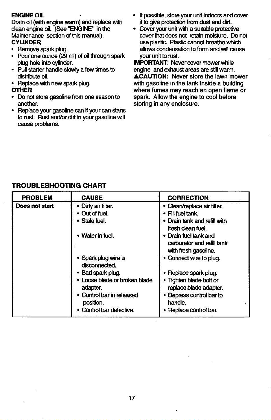
TROUBLESHOOTING CHART
PROBLEM
Does not start
CAUSE
• Dirtyair fiifer.
• Out offuel.
• Stale fuel.
• Water infuel.
• Sparkplug wireis
disconnected.
• Badsparkplug.
• Loosebladeor brokenblade
adapter.
• Controlbarin released
position.
• -Controlbardefective.
CORRECTION
• Clean/replace air fiifer.
• RII fuel tank.
• Drain tank and refillwith
fresh dean fuel.
• Drain fuel tank and
carburetorand refilltank
withfresh gasoline.
• Connect wire to plug.
• Replace spark plug.
• T_ghtenblade boltor
replaceblade adapter.
• Depress controlbar to
handle.
• Replace control bar.
17
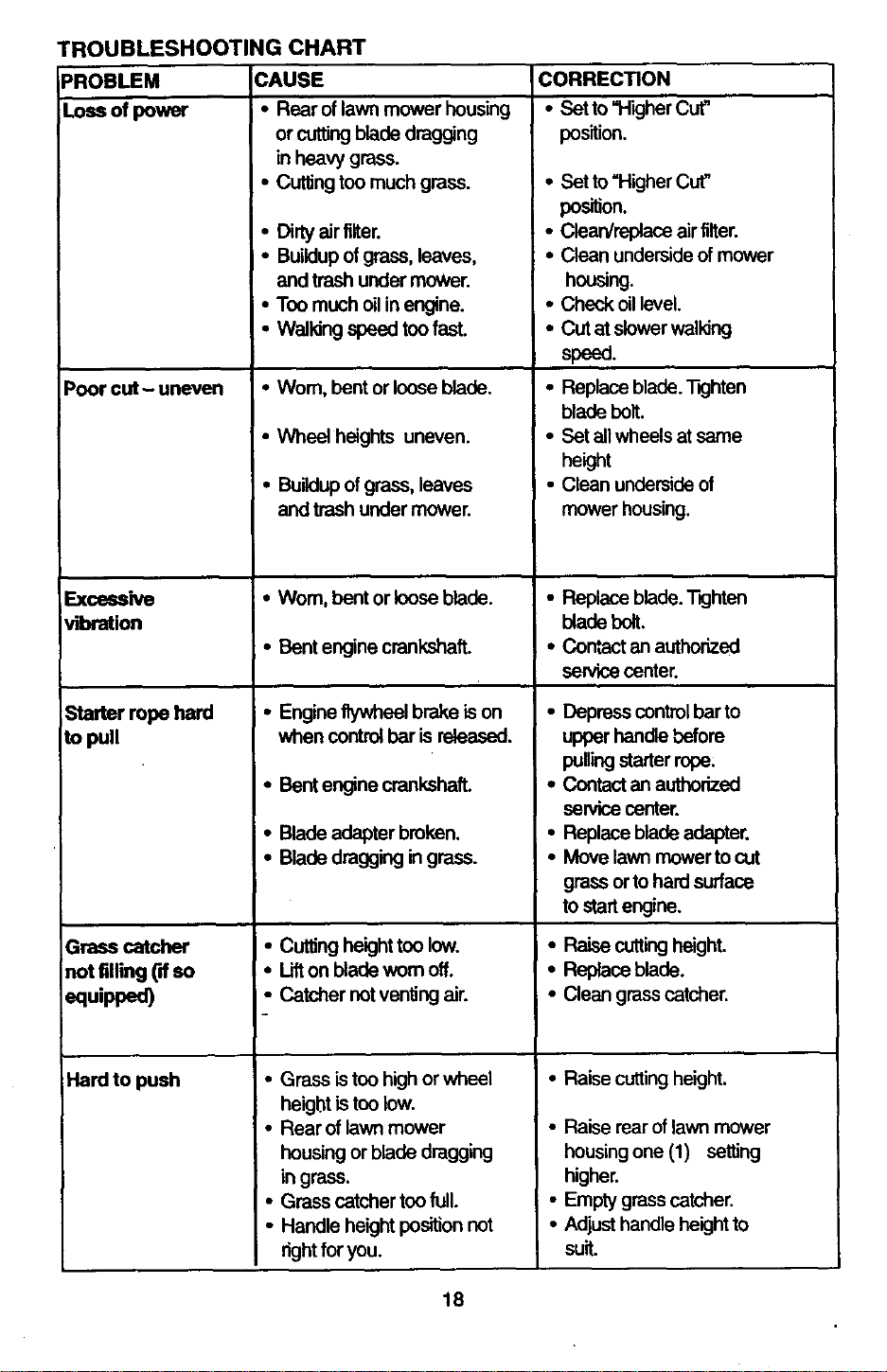
PROBLEM
Loss ofpower
TROUBLESHOOTING CHART
CAUSE
• Rear of lawn mower housing
or cutting blade dragging
in heavy grass.
• Cuttingtoo much grass.
Poor cut- uneven
Excessive
vibration
Starter rope hard
to pull
Grasscatcher
notfilling(ffso
equipped)
Hard to push
• Dirty airfilter.
• Buildupof grass, leaves,
and trash under mower.
• Too m_-'h oilin engine.
• Waildng speed too fast.
•Wom, bent or loose blade.
• Wheel heights uneven.
• Buildupof grass, leaves
and trash under mower.
• Wom, bent or loose blade.
• Bent engine crankshaft.
• Engine flywheel brake ison
when controlbar is released.
• Bent engine crankshaft.
• Blade adapter broken.
• Blade dragging in grass.
• Cuffingheight tee low.
• Lifton blade wom off.
• Catcher notventing air.
• Grass is too highor wheal
heightis tee low.
• Rear of lawn mower
housing or blade dragging
in grass.
• Grass catcher too full.
• Handle height positionnot
rightfor you.
CORRECTION
• Satto "Higher Cut"
pos'dion.
• Bet to =HigherCut"
position.
• Clean/replace air filter.
• Clean undersideofmower
housing.
• Check oillevel.
• Cut at slowerwalking
speed.
• Replace blade.T_jhten
blade belt.
• Set all wheels at same
height
• Clean undersideof
mower housing.
• Replace blade. T_htan
blade bolt.
• Contact an authorized
service center.
• Depress control barto
upper handle before
pullingstarter rope;
• Contactan authorized
service center.
• Replace blade adapter.
• Move lawn mower tocut
grass orto hard surface
to startengine.
• Raise cuttingheight.
• Replace blade.
• Clean grass catcher.
• Raise cutting height.
• Raise rearof lawn mower
housingone (1) setting
higher.
• Empty grasscatcher.
• Adjust handle heightto
suit.
18
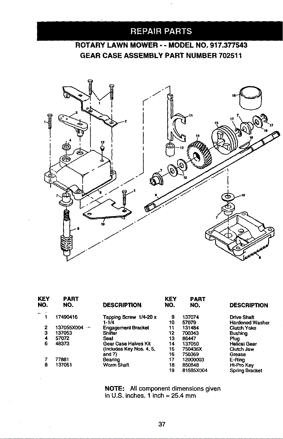
ROTARY LAWN MOWER - - MODEL NO. 917.377543
GEAR CASE ASSEMBLY PART NUMBER 702511
)651o
14
KEY PART
NO. NO.
- 1 17490416
2 137055X004 .'_
3 137053
4 57072
6 48373
7 77881
8 137051
KEY PART
DESCRIPTION NO, NO. DESCRIPTION
Tapping Screw 114-20 x 9 137074 Drive Shaft
1-1/4 10 57079 Hardened Washer
Engagement Bracket 11 131484 Clutch Yoke
Shifter 12 700343 Bushing
Seal 13 86447 Plug
Gear Case Halves Kit 14 137050 Helical Gear
(InCludeS Key Nos. 4, 5, 15 750436X Clutch Jaw
and 7) 16 750369 Grease
Beadng 17 12000003 E-Ring
Worm Shaft 18 850848 Hi-Pro Key
19 S1585X004 Spring Bracket
NOTE: All component dimensions given
in U.S. inches, 1 inch = 25.4 mm
37
38
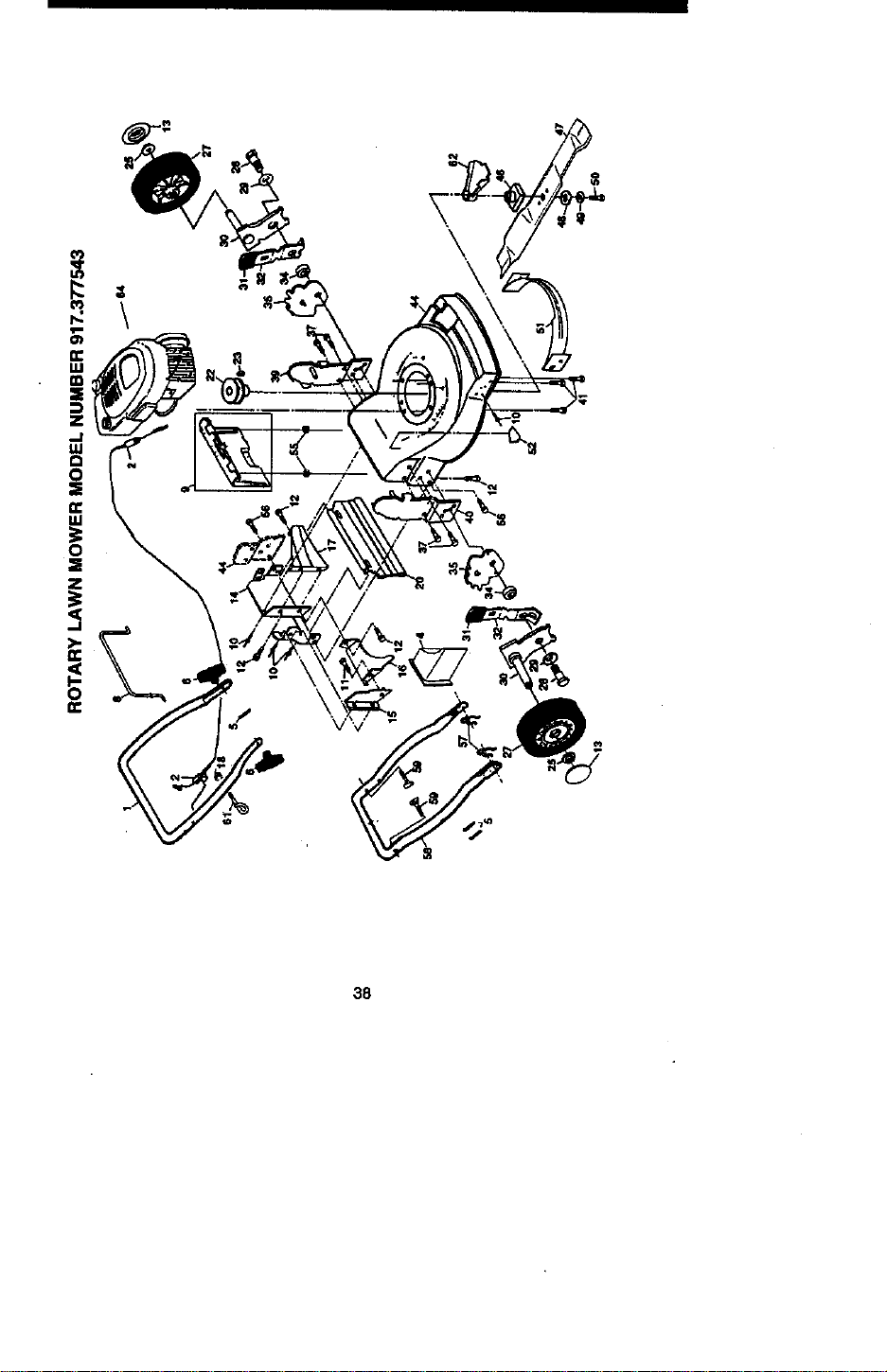
ROTARY LAWN MOWER MODEL NUMBER 917.377543
co
CD
KEy
NO.
1
2
4
6
6
8
g
10
11
12
13
14
15
16
17
18
2O
22
23
25
27
28
29
3O
31
32
34
35
37
39
4O
PART
NO.
165451X479
166577
15O425
66426
136376
145793
151023
128415
13O03O
STD512505
77400
156374X479
7003O5X479
133190X479
140661X479
636O1
14O54O
85543
67677
83923
151158
142748
62335
145S35X004
701037
73O331X004
14663O
700_?.6X607
150078
151512X479
151511x47g
KEY PART
DESCRIPTION NO. NO. DESCRIP_ON
UpperHandle
MEngtneZoneControlCable
ulcherPlug
WireTie
LHandta Knob
ControlBar
Rear DoorKit
PopRivet
Se_fTappingScrew #10-24x 5/8
HexTappingScreww/scms 1/4-20x 1/2
Hubcap
Backplata
Side Baffle
DischargeBaffle
Rear Baffle
Kep=Locknut1/4-20
Rear Skirt
EnginePulley
Hi-ProKey #506
HexFlangeNet
Wheel
ShoulderBolt3/8-16x 1
BetlevilleWeshar
AxleAm1
SelectorKnob
Setecto¢Spdng
Spacer
WheelAdjustingBracket
ThreadCuttingScreww/Barns5/16-18x3/4
HandleBracketAssembly(Left)
HandleBcacketAssembly(Right)
41 1504O6
44 161769
46 851514
47 157101
48 851074
49 850263
50 851084
51 165548
52 85463
55 751592
56 88652
57 51793
58 157081X479
59 131959
61 132001
62 134612
64 ......
- - 161058
•. 166080
Hex Head Thread Rolling Screw 3/8-16 )( 1-1/B
Lawn Mower Housing (JncL Key #14, 15, 51)
Blade Adapter
Blade 22"
Hardened Washer
Helicet Washer 3/8-24 x I •3/8 Gr, 8
Hex Head Machine Screw 3/8-24 x 1-3/8 Gr. 6
Front Baffle
Danger Decal
Locknut 3/8-16
Hinge Screw 1/4-20 x 1-1/4
Hairpin Cotter
Lower Handle
Handle Bolt
Rope Guide
Debds Sh[eJd
Engine - (See Breakdown)
Tecumseh Model No,143.996510
Warning Decal (Not Shown)
Owner's Manual (Englis_Spanish)
Available accessories not included with lawn mower:
.. 71 33303 Clipping Detlectot
.. 71 33623 Gas Can (2,6 gal.)
•. 71 33500 Fuei StabiJIzer
-. 71 33300 SAE 3OW Oil (20 oz.)
-. 71 33417 Dust Shield
-. 7133316 Mower Cover
-. 71 33723 High Wheel Kit
40

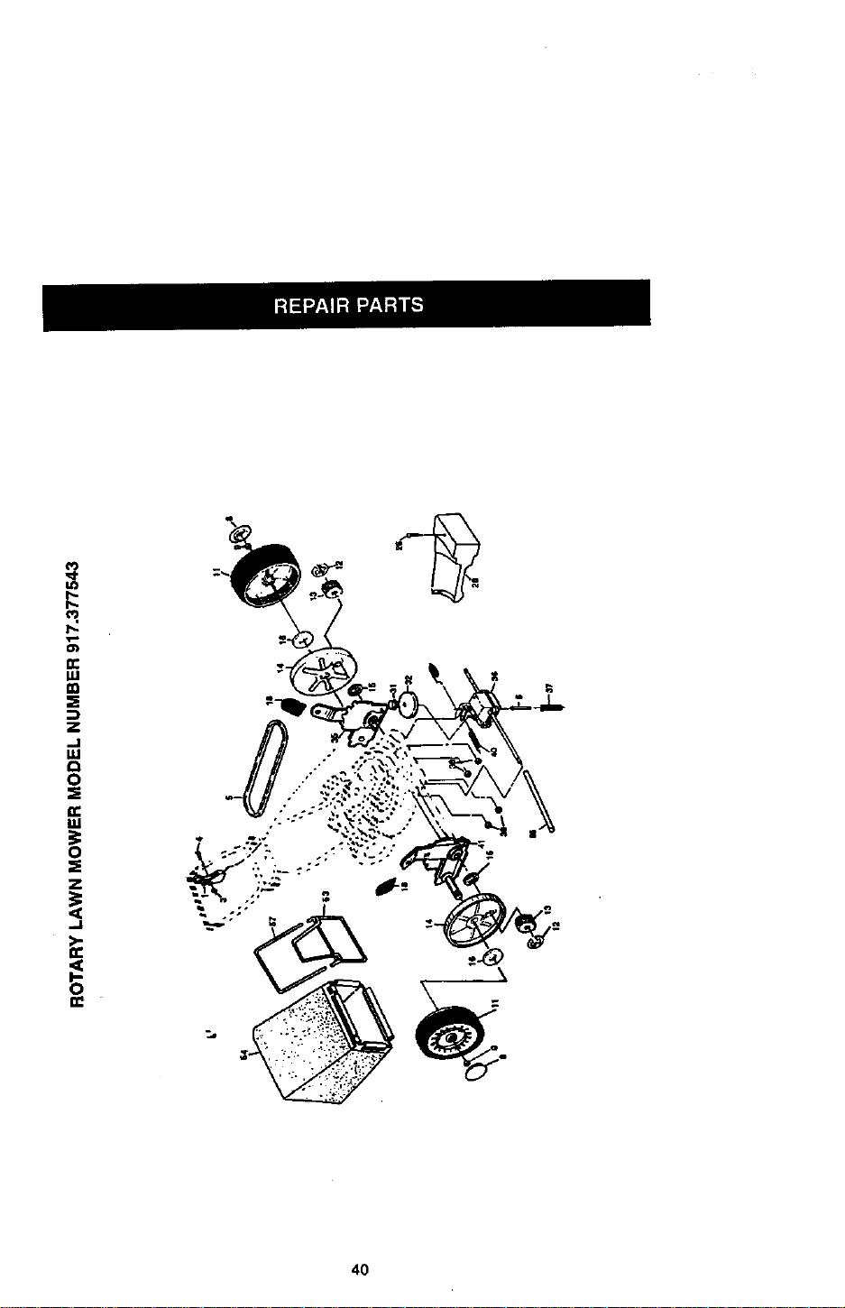
ROTARY LAWN MOWER MODEL NUMBER 917.377543
KEY PART
NO, NO. DESCRIPTION
KEY PART
NO. NO. DESCRIPTION
_" 28 154990
1 145755 C_trOI Cable Assembly 31 132010
3 751152 Locknut #10-24 32 137052
4 158755 Pan Head Machine Screw 1/4 x 2,12 35 151521
5 145527 V-_t 36 702511
6 150495 Spring Retainer 37 137090
5 77400 , Hubcap 38 63601
9 145212 Flanged Nut 40 75192
11 151156 Wheel & Tire AssembJy 41 151520
12 12000058 E-Ring 53 144747
13 137054 Pinion 54 166069
14 88080 Dust Cover 55 86012
15 88118 Felt Weeher 57 144748
16 67725 Washer 1/2 x 1-1/2 x,134
15 701037 Selector Knob
26 143603 Pan Heed Tapping Screw #10-24 x 2-3/4
Drive Cover
Hex Flange Nut
Ddve Pulley
Wheel Adjuster Assemb;y (Left)
Gear Case Assembly
Spring
Nut
Spring
Wheel Adjuster Assembly (Right)
Frame Throat
Grassheg Assembly
Drivechaft Cove,,
Gmssheg Tube
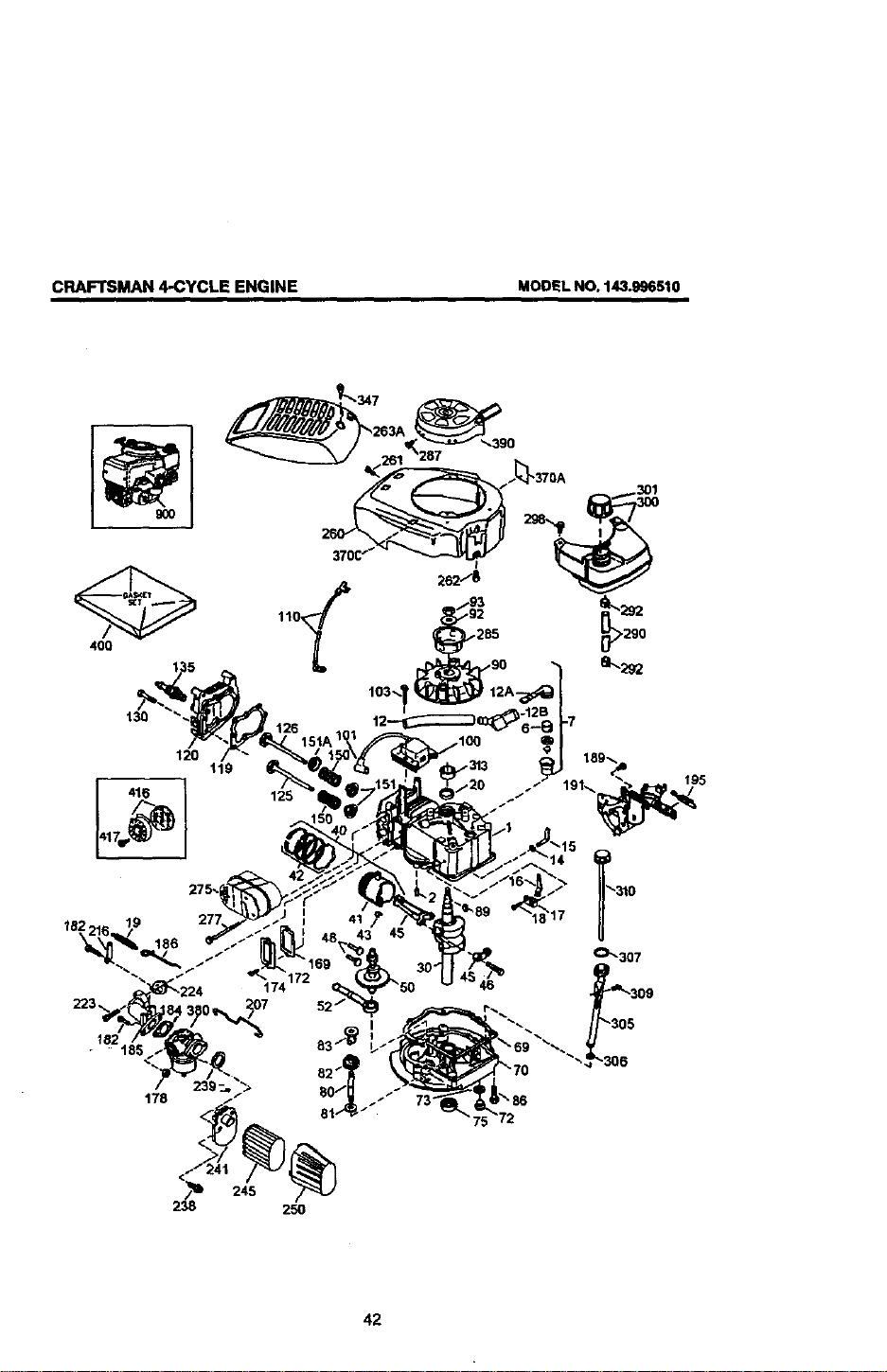
CRAFTSMAN 4-CYCLE ENGINE MODEL NO, 143.996510
400
130
120
416 ]
11g
.285
18 19
174
238 250
73
292
290
42
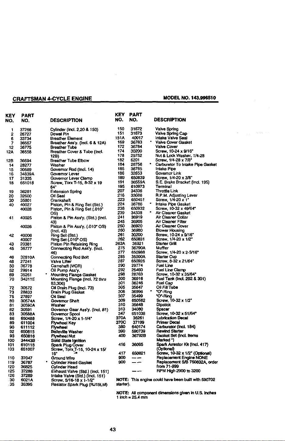
CRAFTSMAN 4-CYCLE ENGINE
MODEL NO. 143.996510
KEY PART KEY PART
NO. NO. DESCRIPTION NO. NO. DESCRIPTION
1 37266 Cylinder (Incl. 2,20 & 150) t50 31672 Valve Swing
2 26727 Dowel Pin t61 31673 Valve Spring Cap
6 33734 Breather Element 151A 40017 Intake Valve Seal
7 36557 Breather Ass_/. (incl. 6 & 12A) 169 36783 * Valve Cover Gasket
12 36775 Breatber Tube t72 36784 Valve Cover
12A 36658 Breather Cover & Tube (Incl. t74 30200 Screw, 10-24 x 9/16"
12B) t78 29752 Nut & Lock Washar, 1/4-28
12B 36694 Breather Tube Elbow t 82 6201 Screw, 1/4-28 x 7/8"
14 28277 Washer 184 26756 • Carburetor To Intake Pipe Gasket
15 30589 Governo_ Rod (Incl. 14) 185 36785 intake Pipe
16 34839A Govemo_ Lever 186 32653 Govemor Link
17 31335 Governor L_NerClamp 189 650839 Screw, 1/4-20 x 3/8"
18 651618 Screw, To(x T-15, 8-32 x 19 191 36559A S.E. Brake Bracket (Incl. 196)
64" 195 610973 Terminal
19 36281 Extension Spring 207 34336 ThrotfteLink
20 32600 Oil Seal 216 33086 R.P.M. Adjusting Lever
30 35801 Crankshaft 223 650451 Screw, 1/4-20 x 1"
40 40027 Piston, Pin & Ring Set (Std.) 224 36766 " Intake Pipe Gasket
40028 Piston, Pin & Ring Set (.010" 238 650932 Screw, 10-32 x 49/64"
OS) 239 34336 " Air Cleaner Gasket
41 40025 Piston & Pin Ass_/, (Std.) {Incl. 241 36918 Air Cleaner Cut]ar
43) 245 36905 Air Cleaner Filter
40026 Piston & Pin Ass_.. (.010" OS) 250 36_0 Air Cleaner Cover
(Incl. 43) 260 36980 Blower Housing
42 40006 Ring Set (Std,!. 261 30200 Screw, 10-24 x 9/16"
40007 Ring Set (.010 OS) 262 650831 Screw, 1/4-20 x 1/2"
43 20381 Piston Pin Retaining Ring 263A 36921 Starter Grill
45 36777 Connec_ng Rod ASS'y. (Incl. 275 36790A Muffler
46) 277 650988 Screw, 1/4-20 x 2-5/16"
46 32610A Connecting Rod Bolt 285 35000A Starter Cup
48 27241 Valve L_ter 287 650926 Screw, 8-32 x 21/64"
SO 36778 Camshaft (MCR) 2gO 29774 Fuel
52 29914 Oit Pump/_ss _/. 292 26460 Fuel Line Clamp
69 35261 * Mounting Flange Gasket 298 28763 Screw, 10-32 x 35/64"
70 34311E Mounting Flange (Ind. 72 thru 300 36916 Fuel Tank {Ind. 292 & 301 )
83,306) 301 36246 Fuel Cap
72 30572 Oil Drain Plug (thcl. 73) 305 35647 Oil Fill Tube
73 28833 Drain Plug Gasket 306 36996 • "O-Ring
75 27897 O_ Seal 307 35499 "(_-Rtog
80 30574A Governor Shaft 309 650562 Screw, 10-32 x 1/2"
81 30590A Washer 310 35648 Dips6dx
82 30591 Governor Gear Ass"/. (Ind. 61) 313 34080 Spacer
83 30588A Governor Spool 347 651038 Screw, 10-32 x 51/64"
86 650488 Screw, 114-20 x 1-1/4" 370A 36261 LubdcaKonDecal
89 611004 Rywbeel Key 370C 37199 Primer Dotal
90 611112 P"l_heel 380 640174 Car_ (IrmL 184)
92 650815 Sellevllle Washer 3_O 590739 Rewind Starter
93 650616 Flywheel Nut 400 36792B Gasket Set (Incl. Items
100 34443B - Solid State Ignition Marked ")
101 610116 Spark Pleg Covet 416 36_85 Sflark Attestor lot (Ind. 417)
f03 651007 Screw, Torx T-15, 10-24 x 15/ (Op_onal)
16" 417 65_21 Screw, 10-32 x 1/2" (Op_onal)
110 37047 Ground Wire 900 -- -- Replacement Engine NONE
119 36787 * C'/6nder Read Gasket 9GO ---- Reptacement S/B 750832A, ocder
f2O 36825 Cylinder Head from 71-999
125 37288 Exhaust Valve (Std.) (Ind. 161) -- _ RPM High 2900 to 3200
126 37289 Intake Valve (Ski. (Incl. 151 )
30 6021A Screw, 5/ 6-18 x 1-1/2" NOTE: "i_is engine could have been bui6 with 590702
35 35395 Reslator Spark Plug (FU19LM) starter).
NOTE: All component dimensions given in U.S. Inches
1 inch = 25.4 mm
43
CRAFTSMAN4-CYCUEENGINE MODEL NO. 143.996510
44
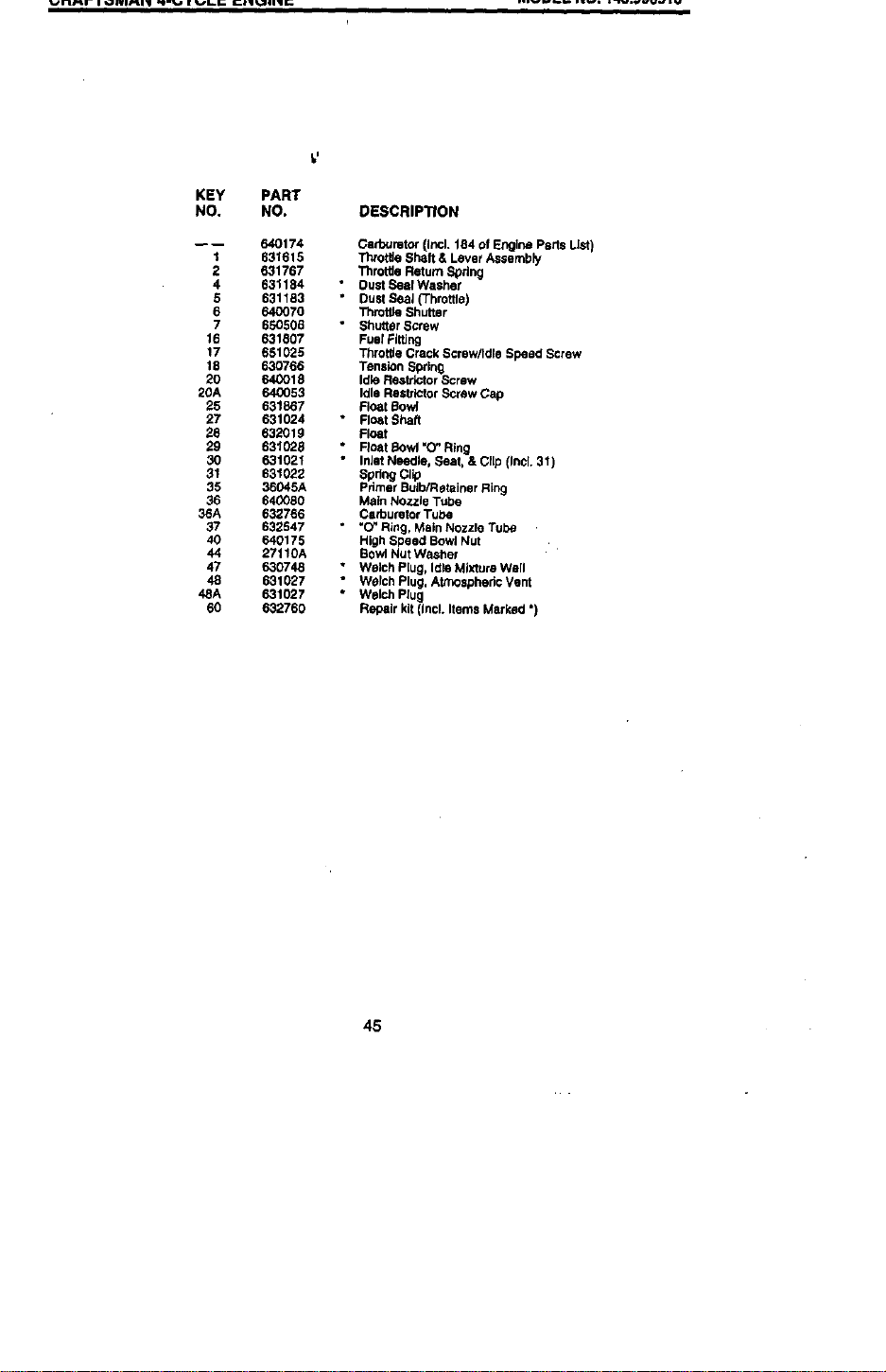
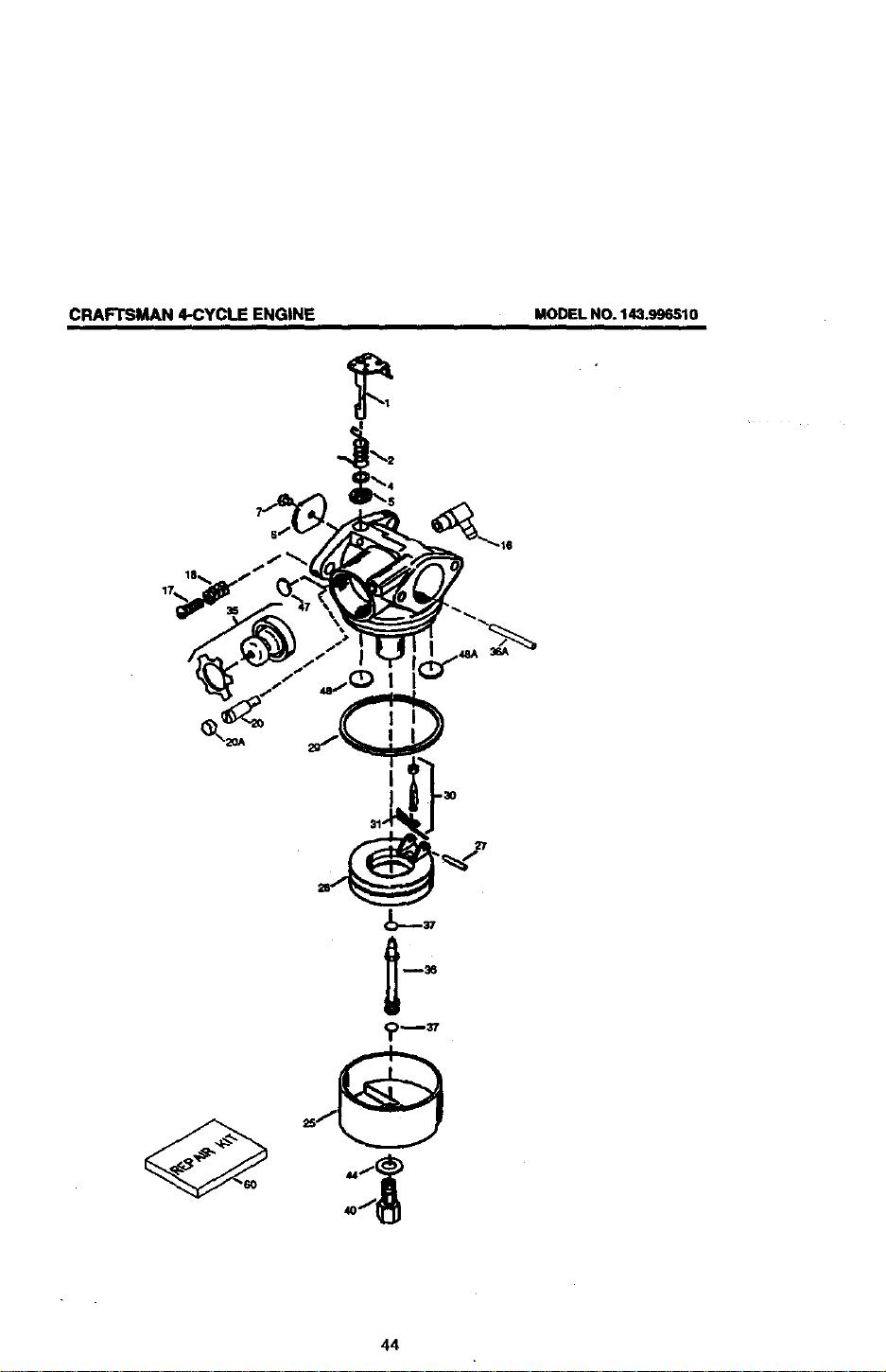
CRAFTSMAN 4-CYCLE ENGINE MODELNO. 143.996510
KEY PART
NO. NO. DESCRIPTION
-- 640174 Carburetor (Ir_,l. 184 of Engine Perts LiStI
1 631615 Thtot6e Shaft & Lever Assembly
2 631767 Throttle Return Spdng
4 631184 " Dust Seal Washer
5 631183 " Dust SeaJ (Throttle)
6 640070 Throltle Shutter
7 650506 " Shutter Screw
16 631807 Fuel Flffing
17 661025 Throt_e Crack Screw/Idle Speed Screw
18 630766 Tension Swing
20 640016 Idk_ResViotor Screw
20A 640053 Idle Restdctor Screw Cap
25 631867 Fleat Sowl
27 631024 ° Float Shaft
28 63201 g Float
29 631028 * Float Bowl =O' Ring
30 631021 " Inlet Needle, Seat, & Clip (Incl. 31)
31 631022 Spdng Cl_p
35 36045A Pdmer Bulb/Releiner Ring
36 640080 Main Nozzle Tube
36A 632766 CeYouretor Tube
37 632547 • "O" Ring, Main Nozzle Tube
40 640175 High Speed Bowl Nut
44 27110A Bowl Nut Washer
47 630748 * Welch Plug, Idle Mixture Well
48 631027 " Welch Plug, Atmosphadc Vent
48A 631027 * Welch Plug
60 632760 Repair kit (incl. Items Marked ")
45
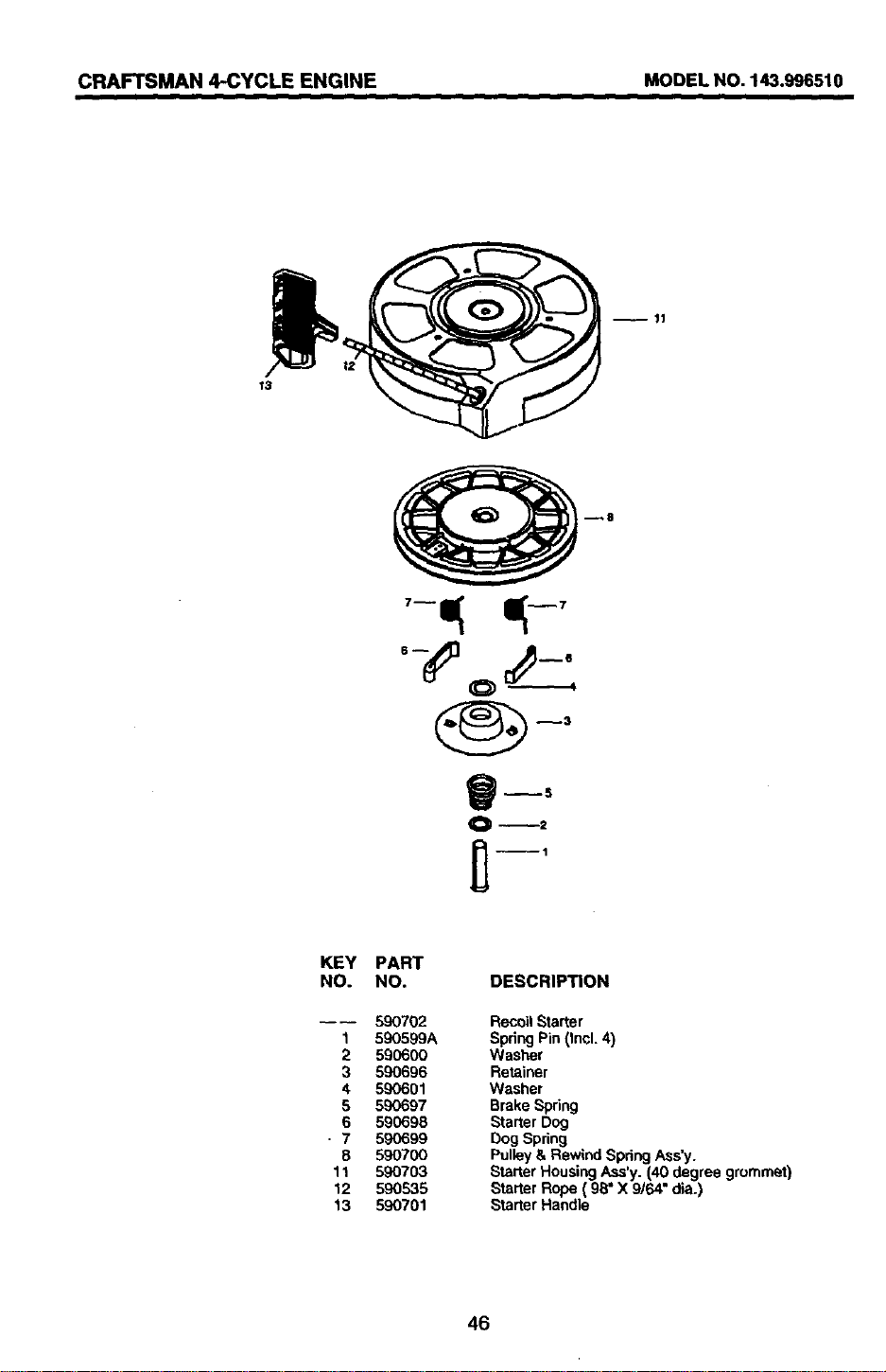
CRAFTSMAN 4-CYCLE ENGINE MODEL NO. 143.996510
O. 143.996510
u 11
r3
KEY
NO.
1
2
3
4
5
6
7
8
11
12
13
PART
NO. DESCRIPTION
---- 590702 Recoil Starter
590599A Spring Pin (Incl. 4)
590600 Washer
590696 Retainer
590601 Washer
590697 Brake Spring
590698 Starter Dog
590699 Dog Spring
590700 Pulley & Rewind Spring Ass'y.
590703 Starter Housing Ass'y. (40 degree grommet)
590535 Starter Rope ( 98" X 9/64" dia.)
590701 Starter Handle
46
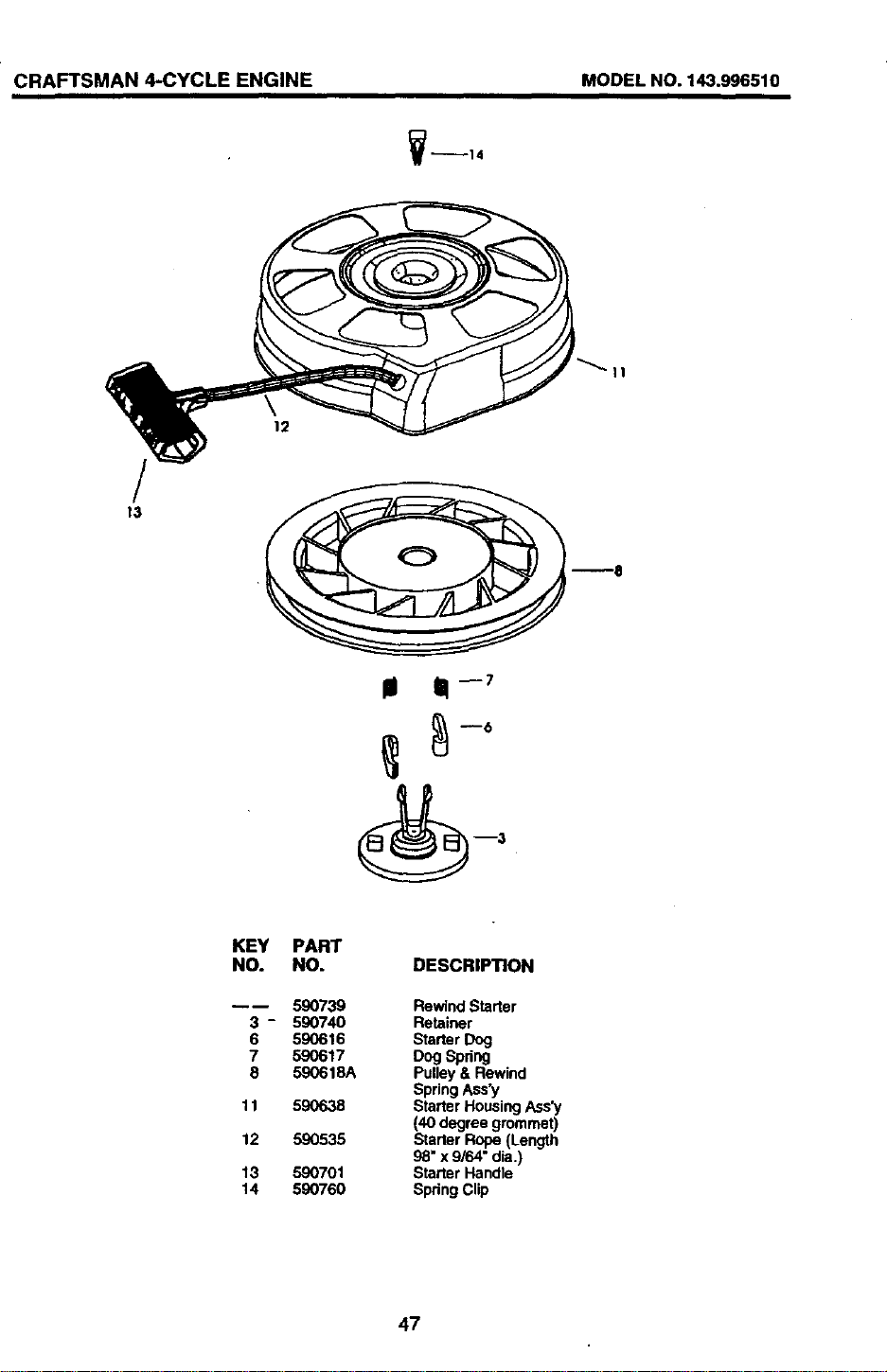
CRAFTSMAN 4-CYCLE ENGINE MODEL NO. 143.996510
_14
/
13
12
_a
III 11_7
KEY PART
NO. NO.
-- 590739
3- 590740
6 590616
7 590617
8 590618A
11 590638
12 590535
13 590701
14 590760
DESCRIPTION
RewindStarter
Retainer
StarterDog
Dog Spdng
Pulley& Rewind
SpringAss'y
StarterHousingAss'y
(40 degree grommet)
StarterRope(Length
98" x 9/64" dia.)
Starter Handle
SpringClip
47
Forthe repair or replacement parts you need
delivered directly to your home
Call 7 am - 7 pro, 7 days a week
1-800-366-PART
(1-800-366-7278)
Para ordenar piezas con entrega a
domicilio - 1-800-659-7084
For in-house major brand repair service
Call 24 hours a day, 7 days a week
1-800-4-REPAIR
(1-800-473-7274)
Para pedir servicio de reparaci6n a
domicilio - 1-800-676-5811
For the location of a Sears Parts and
Repair Center in your area
Call 24 hours a day, 7 days a week
1-800-488-1222
For information on purchasing a Sears
Maintenance Agreement or to inquire
about an existing Agreement
Call 9 am - 5 pm, Monday-Saturday
1-800-827-6655
When requesting service or ordering
parts, always provide the following
information:
• Product Type • Part Number
• Model Number • Part Description
SKARS
America's Repair Specialists
166080 10.14.98 VB/SV Printedin U.S.A.