Loading ...
Loading ...
Loading ...
Fill Line
Fig. 22
4. Refill the crankcase with
3.04 fl.oz. (90 ml) of SAE 30
SF, SG, SH oil.
NOTE: Use the bottle and
spout saved from initial
use to measure the
correct amount of oil.
The top of the label on
the bottle measures
approximately 3.04 fl.oz.
(90 ml) (Fig. 23). Check
the level, See Checking
the Oil Level. If the level
is low, add a small
amount of oil and
recheck. Do not overfill
(Fig. 22).
5. Replace the oil fill plug.
6. Reconnect the spark plug boot.
AIR FILTER MAINTENANCE
Cleaning the Air Filter Fig. 23
-- i_[_ WARNING: To avoid serious personal injury, always turn the 2.
unit off and allow it to cool before cleaning or maintaining it.
First, Check Fuel
Old fuel is usually the reason for improper unit performance. Drain and refill
the tank with fresh fuel prior to making any adjustments. Refer to Oil and
Fuel Information.
Second, Clean Air Filter
The condition of the air filter is important to the operation of the unit. A dirty
air filter will restrict air flow. This is often mistaken for an out of adjustment
carburetor. Check the condition of the air filter before adjusting the idle
speed screw. Refer to Air Filter Maintenance.
Third, Adjust Idle Speed Screw
_ ARNING: The cutting attachment may spin during idle speed
adjustments. Wear protective clothing and observe all safety
instructions to prevent serious personal injury.
If, after checking the fuel and cleaning the air filter, the engine still will not
idle, adjust the idle speed screw as follows:
1. Start the engine and let it run Idle Adjustment
at a high idle for a minute to Screw
warm up. Refer to
Starting/Stopping
Instructions.
Release the throttle trigger
and let the engine idle. If the
engine stops, insert a small
phillips in between the Air
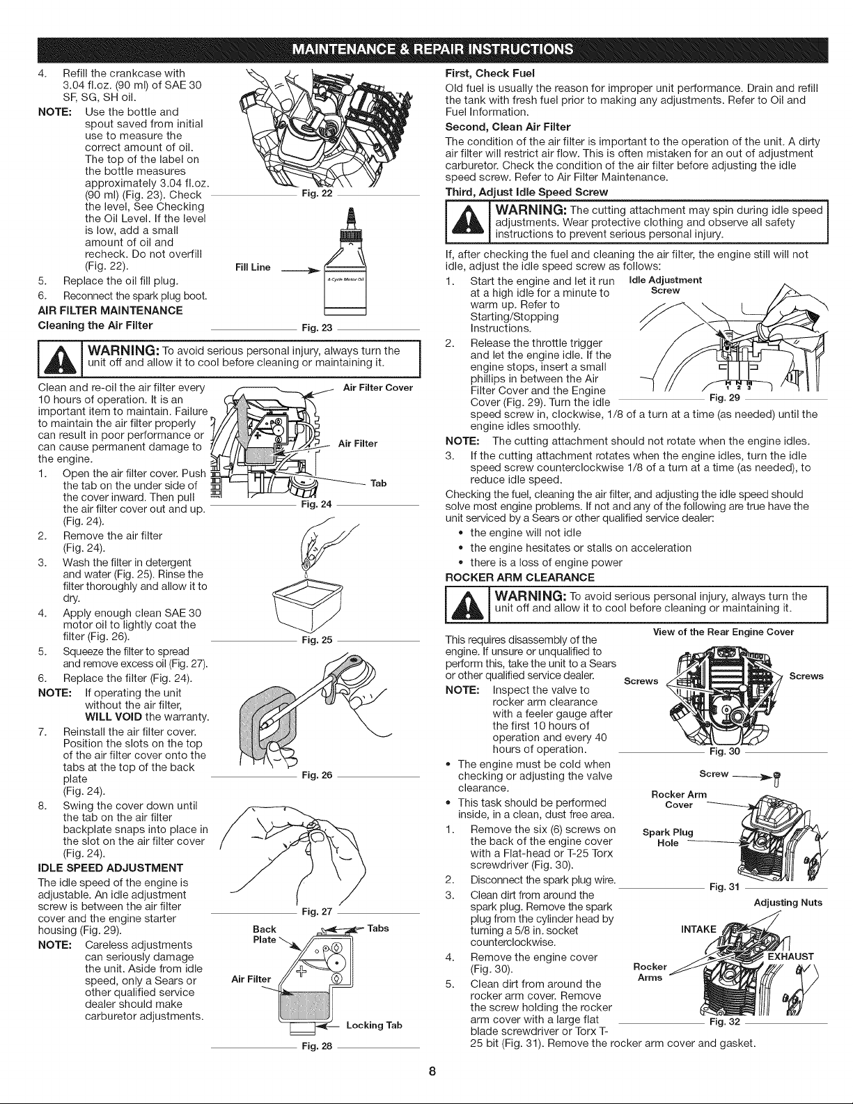
Clean and re-oil the air filter every
10 hours of operation. It is an
important item to maintain. Failure
to maintain the air filter properly
can result in poor performance or
can cause permanent damage to
the engine.
1. Open the air filter cover. Push
the tab on the under side of
the cover inward. Then pull
the air filter cover out and up.
(Fig. 24).
2. Remove the air filter
(Fig. 24).
3. Wash the filter in detergent
and water (Fig. 25). Rinse the
filter thoroughly and allow it to
dry.
4. Apply enough clean SAE 30
motor oil to lightly coat the
filter (Fig. 26).
5. Squeeze the filter to spread
and remove excess oil (Fig. 27).
6. Replace the filter (Fig. 24).
NOTE: If operating the unit
without the air filter,
WILL VOID the warranty.
7. Reinstall the air filter cover.
Position the slots on the top
of the air filter cover onto the
tabs at the top of the back
plate
(Fig. 24).
8. Swing the cover down until
the tab on the air filter
backplate snaps into place in
the slot on the air filter cover
(Fig. 24).
iDLE SPEED ADJUSTMENT
The idle speed of the engine is
adjustable. An idle adjustment
screw is between the air filter
cover and the engine starter
housing (Fig. 29).
NOTE: Careless adjustments
can seriously damage
the unit. Aside from idle
speed, only a Sears or
other qualified service
dealer should make
carburetor adjustments.
Fig. 24
Air Filter Cover
Air Filter
Tab
Fig. 25
Fig. 26
Fig. 27
Fig. 28
Filter Cover and the Engine
Cover (Fig. 29). Turn the idle Fig. 29
speed screw in, clockwise, 1/8 of a turn at a time (as needed) until the
engine idles smoothly.
NOTE: The cutting attachment should not rotate when the engine idles.
3. If the cutting attachment rotates when the engine idles, turn the idle
speed screw counterclockwise 1/8 of a turn at a time (as needed), to
reduce idle speed.
Checking the fuel, cleaning the air filter, and adjusting the idle speed should
solve most engine problems. If not and any of the following are true have the
unit serviced by a Sears or other qualified service dealer:
• the engine will not idle
the engine hesitates or stalls on acceleration
there is a loss of engine power
ROCKER ARM CLEARANCE
I A WARNING: To avoid serious personal injury, always turn the
_un t off and a ow it to cool before cleaning or maintaining it.
View of the Rear Engine Cover
This requires disassembly of the
engine. If unsure or unqualified to
perform this, take the unit to a Sears
or other qualified service dealer.
Screws
NOTE: Inspect the valve to
rocker arm clearance
with a feeler gauge after
the first 10 hours of
operation and every 40
hours of operation.
The engine must be cold when
checking or adjusting the valve
clearance.
Rocker Arm
,, This task should be performed Cover
inside, in a clean, dust free area.
1. Remove the six (6) screws on Spark Plug
the back of the engine cover Hole
with a Flat-head or T-25 Torx
screwdriver (Fig. 30).
2. Disconnect the spark plug wire.
Fig. 31
3. Clean dirt from around the
spark plug. Remove the spark
plug from the cylinder head by
turning a 5/8 in. socket INTAKE
counterclockwise.
4. Remove the engine cover EXHAUST
(Fig. 30). Rocker
Arms
5. Clean dirt from around the
rocker arm cover. Remove
the screw holding the rocker
arm cover with a large flat Fig. 32
blade screwdriver or Torx T-
25 bit (Fig. 31). Remove the rocker arm cover and gasket.
Screws
i
Adjusting Nuts
Loading ...
Loading ...
Loading ...