Loading ...
Loading ...
Loading ...
10 11
INSTALLATION INSTALLATION
Wiring connection for gas cooker
To allow for disconnection of the appliance after installation,
the plug must be accessible after installation�
If the supply cord is damaged, it must be replaced by the
manufacturer, its service agent or similarly qualified persons
in order to avoid a hazard�
Gas connection
Read these points before connecting to the gas supply:
• The cooker inlet connection point has a ½" BSP external
thread� See diagram below�
• An NG regulator or a LPG test point fitting is supplied�
• It is recommended to fit the regulator or test point fitting
to the appliance connection point, then fit either hard
piping or a high level flexible connection (AS/NZS 5601�1
clauses 5�9 and 6�10�1�9) which is then attached to the
consumer hard piping�
• Ensure installation allows withdrawal of appliance�
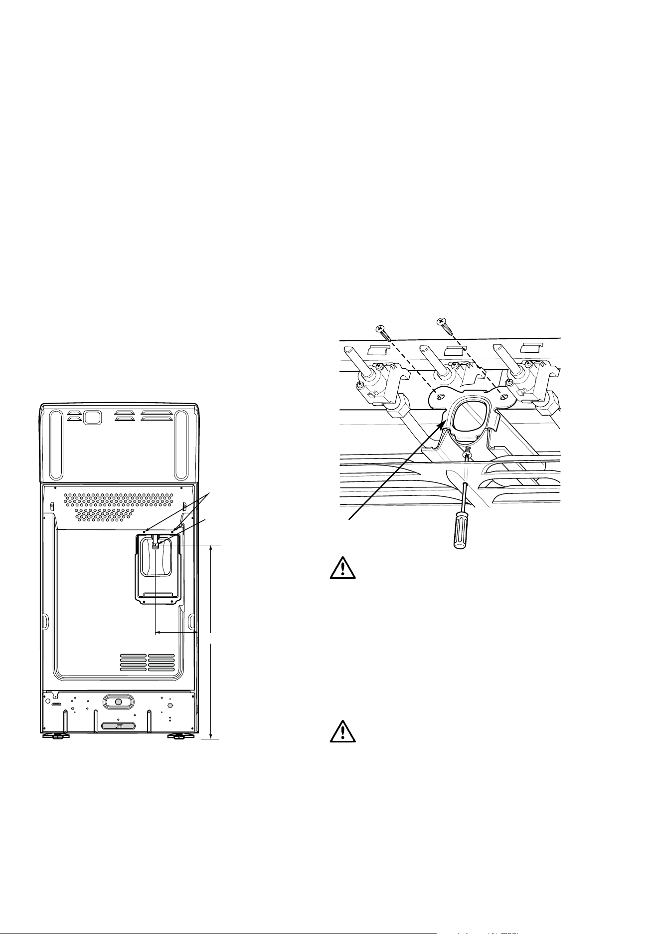
Restraining device
anchor points
Gas connection
point
650mm
150mm
Operation on universal LPG/propane
1� The appliance inlet fitting provided MUST be orientated
so that the pressure nipple is accessible�
2� The inlet fitting has ½" BSP internal thread at the inlet
and outlet�
Operation on SNG
• If the cooker is to be used with SNG, then the grill burner
MUST be modified by the replacement of the shutter,
which fits into the throat of the grill burner�
• A conversion kit can be obtained by contacting the
Customer Care Centre�
Restraining Device
Anchor Points
Connection
Gas
Point
150mm
650mm
Grill shutter
WARNING
WARNING
Disconnect electric power before removing control panel�
1� Remove the control panel�
2� Remove the existing NG shutter securing screw (refer to
diagram above) and slide upwards to disengage from
grill burner�
3� Slide the SNG shutter into position and secure with
screws�
Testing the gas cooker
WARNING
WARNING
You MUST test the cooker after installation, before you hand
it over to the customer.
You MUST have a manometer and a connecting tube.
GAS TYPE NATURAL GAS UNIVERSAL LPG PROPANE
Supply pressure at inlet to appliance
regulator (if fitted)
1�13 (kPa)
Minimum
2�75* (kPa) 2�75* (kPa)
Operating pressure at
appliance test point
1�00 (kPa) 2�75 (kPa) 2�75 (kPa)
* If the regulator is placed upstream of the cooker inlet, as is normal for cookers operating on LPG, then the supply pressure and
operating pressure are the same�
The following table shows the injector sizes for each burner�
INJECTOR NATURAL GAS UNIVERSAL LPG PROPANE
Low heat burner 1�00 mm 0�55 mm 0�62 mm
Medium heat burner 1�35 mm 0�70 mm 0�82 mm
High heat burner 1�60 mm 0�90 mm 0�95 mm
Intense heat wok burner 1�75 mm 1�00 mm 1�00 mm
Grill – main injector 1�50 mm 0�82 mm 0�82 mm
Oven – main injector 1�60 mm 0�82 mm 0�95 mm
Oven – bypass screw 0�73 mm 0�45 mm 0�45 mm
Checking pipe size
To work out a suitable pipe size for connection use the information in this table�
NATURAL GAS UNIVERSAL LPG PROPANE
Configuration
STD
Hob
WOK Hob
STD
Hob
WOK
Hob
STD
Hob
WOK
Hob
Hourly gas consumption for
cooker
58�1MJ 60�2MJ 45�7MJ 48�2MJ 56�5MJ 58�3MJ
Also use information about the length of the run, number of
elbows, tees and bends, the available service pressure and
the supply requirements� AS/NZS 5601�1 will help you with this
matter�
Operation ON NG
• The appliance regulator MUST be orientated so that the
pressure nipple is accessible�
• The arrow showing the direction of flow MUST be
pointed correctly�
• The regulator has a ½” BSP internal thread at the inlet
and outlet�
Gas requirements
This appliance must be installed by an authorised person,
according to all codes and regulations of:
• AS/NZS 5601�1 (particular attention to clause 6�10�1
and figure 6�3 on page 97, and clause 6�10�1�11)
• Local gas fitting regulations, municipal building codes
and other statutory regulations�
Unpacking
When packaging is removed from product you will notice
there are several items nested in the packaging base�
The burner crowns, burner caps and trivets can be fitted to
the hob�
The regulator or test point fitting installation is described in the
front of the manual with UNPACKING�
The cookers come in three gas types:
Natural gas, Propane and Universal LPG� If the cooker is
required to use ULPG, a conversion kit can be obtained by
contacting the Customer Care Centre for details� Before
installation, check that the cooker is suitable for the gas supply
by looking at the data plate behind the bottom of the oven
door�
The following table shows the supply and operating pressures
for various supplies�
Restraining Device
Anchor Points
Connection
Gas
Point
150mm
650mm
NG Regulator
Gas flow
Pressure test
point
1/2" BSP
Internal thread
INSTALLATION
Loading ...
Loading ...
Loading ...