
SEAl, S
®
MODEL NUMBER 917.252561 OWNER'SMANUAL
oAssembly
o Operation
o Customer Responsibilities
o Service and Adjustments
° Repair Parts
®
Conver'l:ibie
CAUTION: Read and follow all safety rules and instructions before operating this equipment.
FOR CONSUMER ASSISTANCE HOT LINE, CALL THIS TOLL FREE NUMBER: 1-800-659-59t7
_ ,,, ....... ,,L ,............... _, • ,,, .....

SAFETY RULES
Safe Operation Practices for Ride-On Mowers
IMPORTANT: THiS CUTTING MACHINE iS CAPABLE OF AMPUTATING HANDS AND FEET AND THROWING OBJECTS.
FAILURE TO OBSERVE THE FOLLOWING SAFETY INSTRUCTIONS COULD RESULT iN SERIOUS INJURY OR DEATH
I. GENERAL OPERATION
. Read, understand, and follow all instructions in the manual
and on the machine before starting
• Only allow responsible adults, who are familiar with the
instructions, to operate the machine
o Clear the area of objects such as rocks, toys, wire, etc,
which could be picked up and thrown by the blade
o Be sure the area is clear of other people before mowing, Stop
machine if anyone enters the area.
• Never carry passengers.
• Do not mow in reverse unless absolutely necessary Always
look down and behind before and while backing.
o Be aware of the mower discharge direction and do not point
it at anyone Do not operate the mower without either the
entire grass catcher or the guard in place,
. Slow down before turning.
= Never leave a running machine unattended, Always turn off
blades, set parking brake, stop engine, and remove keys
before dismounting.
• Turn off blades when not mowing.,
° Stop engine before removing grass catcher or unclogging
chute.
= Mow only in daylight or good artificial light
- Do not operate the machine while under the influence of
alcohol or drugs
. Watch for traffic when operating near or crossing roadways
= Use extra care when loading or unloading the machine into
a trailer or truck
Ii. SLOPE OPERATION
Slopes are a major factor related to loss-of-control and
tipover accidents, which can result in severe injury or death_
All slopes require extra caution, If you cannot back up the
slope or if you feel uneasy on it, do not mow it.
DO:
° Mow up and down slopes, not across.
o Remove obstacles such as rocks, tree Iimbs, etc.
• Watch for holes, ruts, or bumps Uneven terrain could
overturn the machine Talt grass can hide obstacles
. Use slow speed.. Choose a low gear so that you will not have
to stop or shift while on the slope.
• Follow the manufacturer's recommendations for wheel
weights or counterweights to improve stability.
° Use extra care with grass catchers or other attachments
These can change the stability of the machine.
= Keep all movement on the slopes s/ow and gradual. Do not
make sudden changes in speed or direction.
° Avoid starting or stopping on a slope If tires lose traction,
disengage the blades and proceed siowly straight down the
slope_
DO NOT:
o Do not turn on slopes unless necessary, and then, turn slowly
and gradually downhill, if possible
° Do not mow near drop-offs, ditches, or embankments. The
mower could suddenly turn over if a wheel is over the edge
of a cliff or ditch, or if an edge caves in.
• Do not mow on wet grass Reduced traction could cause
sliding
o Do not try to stabilize the machine by putting your foot on the
ground.
o Do not use grass catcher on steep slopes
III. CHILDREN
Tragic accidents can occur if the operator is not alert to the
presence of children. Children are often attracted to the
machine and the mowing activity., Never assume that
children will remain where you last saw them.
,, Keep children out of the mowing area and under the watchful
care of another responsible adult,
° Be aled and turn machine off if children enter the area.
. Before and when backing, look behind and down for small
children.
- Never carry children, They may fall off and be seriously
injured or interfere with safe machine operation.
° Never allow children to operate the machine
- Use extra care when approaching blind corners, shrubs,
trees, or other objects that may obscure vision
IV. SERVICE
° Use extra care in handling gasoline and other fuels, They are
flammable and vapors are explosive,
Use only an approved container
Never remove gas cap or add fuel with the engine
running. Allow engine to cool before refueling, Do not
smoke
Never refuel the machine indoors,,
Never store the machine or fuel container inside where
there is an open flame, such as a water heater,,
° Never run a machine inside a closed area
° Keep nuts and bolts, especla]ly blade attachment bolts, tight
and keep equipment in good condition
° Never tamper with safety devices. Check their proper
operation regularly
. Keep machine free of grass, leaves, or other debris build-up.,
Clean oil or fuel spillage Allow machine to cool before
storing
° Stop and inspect the equipment if you strike an object
Repair, if necessary, before restarting.
° Never make adjustments or repairs with the engine running.
,, Grass catcher components are subject to wear, damage, and
deterioration, which could expose moving parts or allow
objects to be thrown. Frequently check components and
replace with manufacturer's recommended pads, when nec-
essary
° Mower blades are sharp and can cut. Wrap the blade(s) or
wear gloves, and use extra caution when servicing them.
,, Check brake operation frequently. Adjust and service as
required.
"'IHH ' I'r'"r
Look for this symbol to point out im _
portant safety precautions, it means
CAUTION!!! BECOME ALERTtt! YOUR
SAFETY IS INVOLVED.
&
CAUTION: Always disconnect spark plug
wire and placewire where it cannot contact
spark plug in order to prevent accidental
starting when setting up, transporting,
adjusting or making repairs°
2
WARNING A
The engine exhaust from this product con-
tains cliemicals known to the State of Califor-
nia to cause cancer, birth defects, or other
reproductive harm.

CONGRATULATIONS on your purchase of a Sears
Tractor. It has been designed, engineered and manufac-
tured to give you the best possible dependability and
performance.,
Should you experience any problem you cannot easily
remedy, please contact your nearest Sears Authorized
Service Center/Department, We have competent, well-
trained technicians and the proper tools to service or repair
this tractor
Ptease read and retain this manual The instructions wilt
enable you to assemble and maintain your tractor properly,
Always observe the "SAFETY RULES",
MODEL
NUMBER 917.252561
SERIAL
i NUMBER
DATEOFPURCHASE
THE MODEL AND SERIAL NUMBERS WILL BE FOUND
ON A PLATE UNDER THE SEAT.
YOU SHOULD RECORD BOTH SERIAL NUMBER AND
DATE OF PURCHASE AND KEEP iN A SAFE PLACE
FOR FUTURE REFERENCE,
MAINTENANCE AGREEMENT
A Sears Maintenance Agreement is available on this prod-
uct Contact your nearest Sears store for details.
CUSTOMER RESPONSIBILITIES
o Read and observe the safety rules.
o Follow a regular schedule in maintaining, caring for and
using your tractor.
• Follow the instructions under "Customer Responsibili-
ties" and "Storage" sections of this owner's manual
LIMITED TWO YEAR WARRANTY ON
PRODUCT SPECIFICATIONS
HORSEPOWER: 1g 0
GASOLINE CAPACITY 3 5 GALLONS
AND TYPE: UNLEADED REGULAR
OIL TYPE (APi-SF/SG): SAE 30 (above 32°F)
SAE 5W-30 (below 32°F)
OIL CAPACITY: 3.0 PINTS
SPARK PLUG: CHAMPION RJ-19LM
(GAP: 030") STD361458
VALVE CLEARANCE: INTAKE: 004" - 006"
EXHAUST: 007"- 009"
GROUND SPEED (MPH): FORWARD:
1st 1 14
2nd 1 50
3rd 2.34
4th 3 50
5th 4 50
6th 5 70
REVERSE: t 80
TIRE PRESSURE: FRONT: 14 PSI
REAR: 10 PSI
CHARGING SYSTEM: 3 AMPS BATTERY
5 AMPS HEADLIGHTS
BLADE BOLT TORQUE: 30-35 FT LBS
WARNING: This tractor is equipped with an internal
combustion engine and should not be used on or near any
unimproved forest-covered, brush-covered or grass-cov-
ered land unless the engine's exhaust system is equipped
with a spark arrester meeting applicable local or state laws
(if any). If a spark arrester is used, it should be maintained
in effective working order by the operator
In the state of California the above is required by law
(Section 4442 of the California Public Resources Code)
Other states may have similar taws,. Federal laws apply on
federal lands. A spark arrester for the muffler is available
through your nearest Sears Authorized Service Center/
Department (See REPAIR PARTS section of this manual).
i i iiiillllllllll, iiiilll,,lll i
CRAFTSMAN RIDING EQUIPMENT
For two (2) years from the date of purchase, if this Craftsman Riding Equipment is maintained, lubricated and tuned up according
to the instructions in the owner's manual, Sears will repair or replace, free of charge, any parts found to be defective in material or
workmanship.
This Warranty does not cover:
. Expendable items which become worn during normal use, such as blades, spark plugs, air cleaners, belts, etc
• Tire replacement or repair caused by punctures from outside objects, such as nails, thorns, stumps, or glass.
- Repairs necessary because of operator abuse, negligence, improper storage or accident or the failure to maintain the
equipment according to the instructions contained in the owner's manual
- Riding equipment used for commercial or rental purposes
LIMITED 90 DAY WARRANTY ON BATTERY
For ninety (g0) days from dale of purchase, if any battery included with this riding equipment proves defective in material or
workmanship and our testing determines the battery will not hold a charge, Sears wi!l replace the battery at no charge
IN-HOME WARRANTY SERVICE ON YOUR CRAFTSMAN RIDING EQUIPMENT IS AVAILABLE AT NO-CHARGE FOR 30
DAYS FROM THE DATE OF PURCHASE PLEASE CONTACT YOUR NEAREST SERVICE CENTER, AFTER 30 DAYS FROM
THE DATE OF PURCHASE, WARRANTY SERVICE IS AVAILABLE BY TAKING YOUR CRAFTSMAN RIDING EQUIPMENT TO
YOUR NEAREST SEARS SERVICE CENTER. (iN-HOME WARRANTY SERVICE WILL STILL BE AVAILABLE AFTER 30 DAYS
FROM THE DATE OF PURCHASE BUT A STANDARD TRIP CHARGE WILL APPLY,) THIS WARRANTY APPLIES ONLY
WHILE THIS PRODUCT iS IN THE UNtTED STATES
This Warranty gives you specific legal rights, and you may also have other rights which may vary from state to state.
SEARS, ROEBUCK AND CO., D/8t7 WA, HOFFMAN ESTATES, iL 60179
i iiiii iiN,i,i
TABLE OF CONTENTS
SAFETY RULES ............................................................ 2
PRODUCT SPECIFICATIONS ...................................... 3
CUSTOMER RESPONSIBILITIES ...................... 3, 15-18
WARRANTY ....................... :.......................................... 3
TRACTOR ACCESSORIES .......................................... 5
ASSEMBLY .................................................................. 7-9
OPERATION ............................................................ 10-14
MAINTENANCE SCHEDULE ..................................... 15
SERVlCE AND ADJUSTMENTS ........................... 19-24
STORAG E .................................................................... 25
TROUBLESHOOTING ........................................... 26-27
REPAIR PARTS - TRACTOR ................................ 30-47
REPAIR PARTS - ENGINE .................................... 48-53
PARTS ORDERING/SERVICE ............... BACK COVER
INDEX
A
Accessories ................................... 5
Adjustments:
Brake ........................................... 21
Carburetor ........................ 24
Mower
FronFTo-Back ................... 20
Side-To-Side ................... 20
Throttle Control Cable .......... 23
Air Filter, Engine ................ t7-18
Air Screen, Engine .......................... 18
Assembly ............................................ 7-9
B
Battery:
Charging ............................ 8
Cleaning .............................. 17
Starting with Weak Battery .... 22
Storage ............................................. 25
Terminals ........................................ 17
Belt:
Motion Drive
Removal/Replacement ...... 2t
Mower Blade(s)
Removal/Replacement ........ 21
Blade:
Sharpening .................................. 16
Replacemenl .............................. 16
Blake Adjustment ................. 21
C
Carburetor Adjustment ................. 24
Controls, Tractor ...................... 11
Customer Responsibilities .......... 15-18
Engine:
Air Filter .....................................
Air Screen, Engine ................ 18
Cooling Fins, Engine ............... 18
Engine Oil ............................ 17
Fuel Filter ......................... 18
Spark Plug(s) ............................. 18
Tractor:
Battery ................................... 17
Blade .................................. l 6
Lubrication Chart ...................... 15
Maintenance Schedule ............ 15
Tire Care ..................... 8,16,22
Transaxfe ................... 17
Cutting Height, Mower ................... 12
E
Electrical:
interlocks and Relays ........... 23
Schematic ............................ 29
Wiring Diagram ........................... 30
Engine:
Air Filter ................................. 18
Air Screen ........................................ 18
Cooling Fins, Engine ............... !8
Oil Change ..................................... 17
Oil Level ........................... 13,17
Oil Type ...................................... 17
Preparation ......................... 13
Repair Parts ............................ 30-47
Starting ................................... 14
Storage ................................. 25
F
Filter:
Air Filter ............................ 17-18
Fuel .................................... 17-18
Fuel:
Type ......................................... 13
Storage ........................................ 25
Fuse ........................................ 23
H
Hood Removal/Installation ................ 23
L
Leveling Mower Deck ....................... 20
Lubrication:
Chart ............................. 15
Maintenance Schedule ............... 15
Mower:
Adjustment, Front-to-Back ........ 20
Adjustment, Side-to-Side ...............20
Blade Sharpening ....................... 16
Blade Replacement ................ 16
Cutting Height ................ 12
Installation .................................... 19
Operation ............................. 13
Removal .............................. lg
Mowing Tips ...................................... 14
Muffler ............................................. 18
Spark Arrester .............................. 3,40
O
Oi!:
Cold Weather Conditions ........ 13,17
Engine .................................. 13,17
Storage .................................... 25
Operation ....................................... 10-14
Operating Mower .................... 13
Options:
Accessories .................................... 5
Spark Arrester .................... 3,40
P
Parking Brake ............................. 12
Parts Bag ............................................. 6
Parts, Replacement/Repair 30-47
Product Specifications ......................... 3
R
Repair Parts .................................... 30-47
S
Safety Rules ............................... 2
Seat ................................................ 8
Service and Adjustments ................. 19-24
Carburetor ................................ 24
Fuse ................................................ 23
Hood Removal/Installation ..... 23
Motion Drive Belt
Remova!/Replacement ........... 21
Mower Belt(s)
Removal/Replacement ........ 21
Mower Adjustment
Front-to-Back ........................... 20
Side-to-Side .............................. 20
Mower Removal .............................. 19
Tire Care ....................... 8,16,22
Slope Guide Sheet ................. 55
Spark Plug(s) .................................. 18
Specifications .................................... 3
Starting the Engine ................. 13-14
Steering Wheel ............................ 7,22
Stopping the Tractor ............................. 12
Storage ........................................... 25
T
Throttle Control Cable Adjustment .... 23
Tires ........................................... 8,16,22
Trouble Shooting Chart ............ 26-27
Transaxle ................................ 17
W
Warranty ........................................ 3
Wiring Diagram ........................ 29
Wiring Schematic ............................... 30
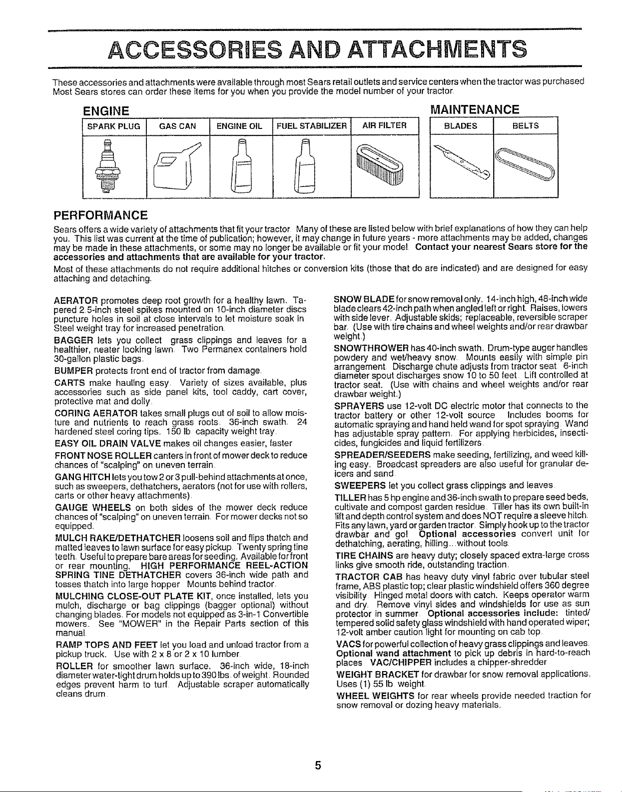
ACCESSORIES AN ATTACHMENTS
These accessories and attachments were available through most Sears retail outlets and service centers when the tractor was purchased
Most Sears stores can order these items for you when you provide the model number of your tractor.
ENGINE MAINTENANCE
SPARK PLUG GAS CAN ENGINE OIL FUEL STABILIZER AIR FILTER BLADES BELTS
PERFORMANCE
Sears offers a wide variety of attachments that fit your tractor Many of these are listed below wlth brief explanations of hew they can help
you. This list was current at the time of publication; however, it may change in future years - more attachments may be added, changes
may be made in these attachments, or some may no longer be available or fit your model Contact your nearest Sears store for the
accessories and attachments that are available for your tractor,
Most of these attachments do not require addltional hitches or conversion kits (those that do are indicated) and are designed for easy
attaching and detaching.
AERATOR promotes deep root growth for a healthy lawn. Ta-
pered 2 5-inch steei spikes mounted on lO-inch diameter discs
puncture holes in soit at close intervals to let moisture soak in
Steel weight tray for increased penetration.
BAGGER lets you collect grass clippings and leaves for a
healthier, nearer looking lawn Two Permanex containers hold
30-gallon plastic bags.
BUMPER protects front end of tractor from damage.
CARTS make hauling easy. Variety of sizes available, plus
accessories such as side panel kits, tool caddy, cart cover,
protective mat and deity.
CORING AERATOR takes small plugs out of soil to allow mois-
ture and nutrients to reach grass roots. 36-inch swath. 24
hardened steel coring tips. 150 lb capacity weight tray.
EASY OIL DRAIN VALVE makes oil changes easier, faster
FRONT NOSE ROLLER canters infront of mower deck to reduce
chances of "scalping" on uneven terrain
GANG HITCH lets you tow 2 or3 pull-behind attachments at once,
such as sweepers, dethatchers, aerators (not for use with rollers,
carts or other heavy attachments).
GAUGE WHEELS on both sides of the mower deck reduce
chances of "scalping" on uneven terrain. For mower decks not so
equipped_
MULCH RAKF_JDETHATCHER loosens soil and flips thatch and
matted leaves to lawn surface for easy pickup Twenty spring line
teeth. Useful to prepare bare areas for seeding. Available for front
or rear mounting. HIGH PERFORMANCE REEL-ACTION
SPRING TINE DETHATCHER covers 36-inch wide path and
tosses thatch into large hopper Mounts behind tractorr
MULCHING CLOSE-OUT PLATE KIT, once installed, lets you
mulch, discharge or bag clippings (bagger optional) without
changing blades. For models not equipped as 3-in-1 Convertible
mowers.. See "MOWER" in the Repair Parts section of this
manuaf
RAMP TOPS AND FEET let you load and unload tractor from a
pickup truck.. Use with 2 x 8 or2 x 10 lumber
ROLLER for smoother lawn surface. 36-inch wide, 18-inch
diameterwater-tight drum holds up to 390 tbs. of weight Rounded
edges prevent harm to turf Adjustable scraper automaticafly
cleans drum
SNOW BLADE for snow removal only. 14-inch high, 48-inch wide
blade clears 42-inch path when angled left or right. Raises, lowers
with side lever Adjustable skids; replaceable, reversible scraper
bar. (Use with tire chains and wheel weights and/or rear drawbar
weight )
SNOWTHROWER has 40-inch swath.. Drum-type auger handles
powdery and wet!heavy snow Mounts easily with simple pin
arrangement Discharge chute adjusts from tractor seat 6-inch
diameter spout discharges snow 10 to 50 feet Lift controlled at
tractor seat. (Use with chains and wheel weights and/or rear
drawbar weight°)
SPRAYERS use 12-volt DC electric motor that connects to the
tractor battery or other 12-veil source lndudes booms for
automatic spraying and hand held wand for spot spraying Wand
has adjustable spray pattern. For applying herbicides, insecti-
cides, fungicides and liquid fertilizers.
SPREADER/SEEDERS make seeding, fertilizing, and weed kill-
ing easy. Broadcast spreaders are also useful for granular de-
icers and sand
SWEEPERS iet you collect grass clippings and Ieaves
TILLER has 5 hp engine and 36-inch swath to prepare seed beds,
cultivate and compost garden residue Tilter has its own built-in
lift and depth control system and does NOT require a sleeve hitch.
Fits any lawn yard or garden tractor Simply hook up to the tractor
drawbar and go! Optional accessories convert un t for
dethatching, aerating, hilling rrWithouttoots.
TIRE CHAINS are heavy duty; closely spaced extra-large cross
links give smooth ride, outstanding traction
TRACTOR CAB has heavy duty vinyF fabric over tubular steel
frame, ABS plastic top; clear plastic windshield offers 360 degree
visibility Hinged metal doors with catch. Keeps operator warm
and dry. Remove vinyl sides and windshields for use as sun
protector in summer Optional accessories include: tinted/
tempered solid safety glass windshield with hand operated wiper;
12-volt amber caution light for mounting on cab top
VACS for powerful collection ef heavy grass clippings and leaves
Optional wand attachment to pick up debris in hard-to-reach
places VAC/CHIPPER includes a chipper-shredder
WEIGHT BRACKET for drawbar for snow removal applications.
Uses (1) 55 Ib weight.
WHEEL WEIGHTS for rear wheels provide needed traction for
snow removal or dozing heavy materials..
5

CONTENTS OF HARDWARE PACK
;1_:;_ .................. ,,,,,,,.............,,,,,,,,,,,,,, ........ ,,,,
, i
Parts Bag contents shown full size
©
(2) Sheet
Metal
Screws
#10-16 x t/2
(1) Locknut 3/8-24
(1) Large Flat Washer
i,,n,,ll , i i ,i i i ,i
(t) Shoulder Bolt 5/16-18 (1) Hex Bolt 1/2-13 x 1
@
O
(1) Lock Washer t/2
(1) Washer 17/32 x 1-3/16 x 12 Gauge
(2) Screws #10 x 5t8 (2) Lock Washers #10 _-}
(2) Weld Nuts #t0
"_=,,,,.J(2) Washers 3/16 x 3/4 x 16 Gauge
.i,._ll[Ui
(2) Hex Bolts 1/4-20 x 3/4
(2) Hex Nuts 1/4-20
(2) Washers 9/32 x 5/8 x t6 Gauge
(2) Lock Washers t/4
,i, i ,,,,i,iiii1,,,,i,i ,, ii i,
Parts packed separately in carton
Seat
Steering
Wheel
Parts Bag
_ Mulcher
Plate
Video
Cassette
Steering
Boot
Manual
Parts bag contents not shown full size
Wheels
(2) Shoulder (2) Washers 3/8
Bolts x 7/8 x 14 Gauge
Steering _ (2) Center-
Wheel \_J lock Nuts
Adapter
@ teering
Bushing
Assemblys
(2) Keys
_ Steering Wheel
Insert
Slope Sheet
6
ASS LY
Your new tractor has been assembled at the factory with exception of those parts left unassembled for shipping purposes.
To ensure safe and proper operation of your tractor, all parts and hardware you assemble must be tightened securely., Use
the correct tools as necessary to insure proper tightness.
TOOLS REQUIRED FOR ASSEMBLY
A socket wrench set will make assembly easier. Standard
wrench sizes are listed,
(1) 5/16" wrench (1) 9/16" wrench
(2) 7t16" wrenches (1) Phillips screwdriver
(1) 1/2" wrench Utility knife
(1) 3/4" wrench Tire pressure gauge
(1) 3/4" socket with drive ratchet
When right and left hand is mentioned in this manual, it
means when you are in the operating position (seated
behind the steering wheel),,
TO REMOVE TRACTOR FROM CARTON
UNPACK CARTON
o Remove al! accessible loose parts and parts cartons
from carton (See page 6).
• Cut, from top to bottom, along lines on all four corners
of carton, and lay panels flato
o Check for any additional loose parts or cartons and
remove
BEFORE ROLUNG TRACTOR OFF SKID
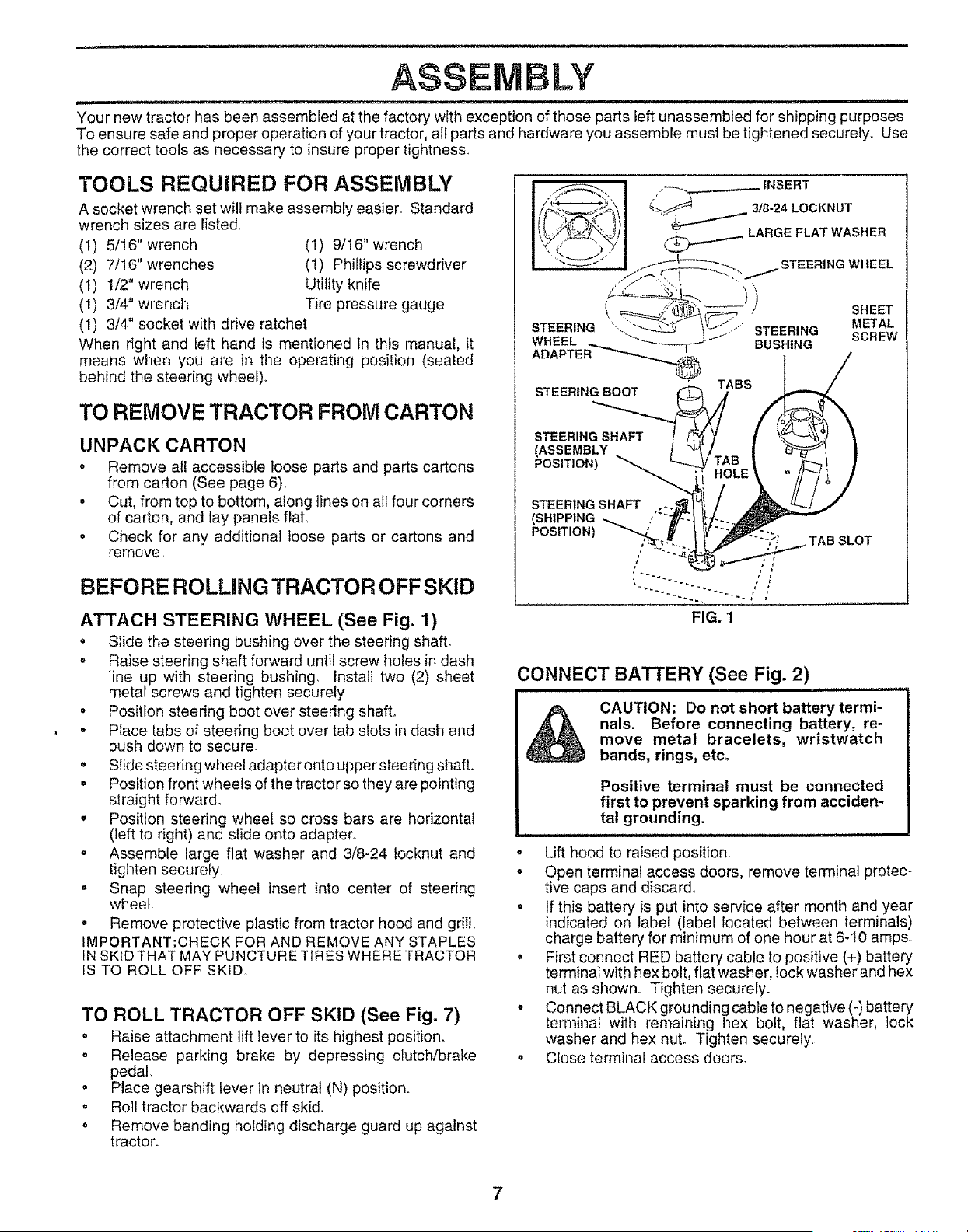
ATTACH STEERING WHEEL (See Fig. 1)
• Slide the steering bushing over the steering shafL
o Raise steering shaft forward until screw holes in dash
line up with steering bushing, Install two (2) sheet
metal screws and tighten securely,
o Position steering boot over steering shaft.
• Place tabs of steering boot over tab slots in dash and
push down to secure.
o Slide steering wheel adapter onto upper steering shaft.
. Position front wheels of the tractor so they are pointing
straight forward.
• Position steering wheel so cross bars are horizontal
(left to right) and slide onto adapter.
o Assemble large flat washer and 3/8-24 Iocknut and
tighten securely.
o Snap steering wheel insert into center of steering
wheel,
o Remove protective plastic from tractor hood and grill,
IMPORTANT:CHECK FOR AND REMOVE ANY STAPLES
IN SKID THAT MAY PUNCTURE TIRES WHERE TRACTOR
IS TO ROLL OFF SKID.
TO ROLL TRACTOR OFF SKID (See Fig. 7)
o Raise attachment lift lever to its highest position.
. Release parking brake by depressing clutch/brake
pedal,
• Place gearshift lever in neutral (N) position.
= Roll tractor backwards off skid.
o Remove banding holding discharge guard up against
tractor.
STEERING SHAFT
(ASSEMBLY
POSITION)
STEERING SHAFT
(SHIPPING ,,:Z:
POSITION) ""'--.--.
TAB SLOT
CONNECT BATrERY (See Fig. 2)
&
CAUTION: Do not short battery termi-
nals. Before connecting battery, re-
move metal bracelets, wristwatch
bands, rings, etc.
Positive terminal must be connected
first to prevent sparking from acciden-
tal grounding.
- Lift hood to raised position
o Open terminal access doors, remove terminal protec-
tive caps and discard°
o If this battery is put into service after month and year
indicated on label (label located between terminals)
charge battery for minimum of one hour at 6_10 amps,
, First connect RED battery cable to positive (+) battery
terminal with hex bolt, flat washer, lock washer and hex
nut as shown_ Tighten securely.
o Connect BLACK grounding cable to negative (-) battery
terminal with remaining hex bolt, fiat washer, lock
washer and hex nuL Tighten securely,
Close terminal access doors.
7
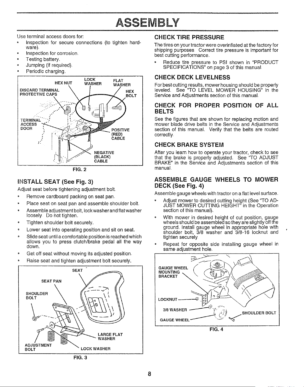
Use terminal access doors for:
o Inspection for secure cennections (to tighten hard_
ware).
• inspection for corrosion.
, Testing battery..
o Jumping (if required).
• Periodic charging,
HEX NUT
DISCARDTERMINAL
PROTECTIVE CAPS
LOCK FLAT
WASHER WASHER
ASSEMBLY
CHECK TIRE PRESSURE
The tires on your tractor were overinfiated at the factory for
shipping purposes Correct tire pressure is important for
best cutting performance.,
o Reduce tire pressure to PSI shown in "PRODUCT
SPECIFICATIONS" on page 3 of this manual
CHECK DECK LEVELNESS
For best cutting results, mower housing should be properly
HEX leveled. See "TO LEVEL MOWER HOUSING" in the
BOLT Service and Adjustments section of this manual.
CHECK FOR PROPER POSITION OF ALL
TERMINAL*" --t
ACCESS
DOOR :
POSITIVE
(RED)
CABLE
NEGATIVE
(BLACK)
CABLE
FIG. 2
See the figures that are shown for replacing motion and
mower blade drive belts in the Service and Adjustments
section of this manual. Verify that the belts are routed
correctly,
CHECK BRAKE SYSTEM
After you learn how to operate your tractor, check to see
that the brake is properly adjusted, See "TO ADJUST
BRAKE" in the Service and Adjustments section of this
manual
INSTALL SEAT (See Fig. 3)
Adjust seat before tightening adjustment bolt,
. Remove cardboard packing on seat pan_
= Place seat on seat pan and assemble shoulder boil
= Assemble adjustment bolt, lock washer and flat washer
loosely Do not tighten.
o Tighten shoulder bolt securely.
o Lower seat into operating position and sit on seat.
o Slide seat until a comfortable position is reached which
allows you to press clutch/brake pedal all the way
down.
o Get off seat without moving its adjusted position.
o Raise seat and tighten adjustment bolt securely.
SEAT
SEAT PAN
SHOULDER
BOLT
I
LARGE FLAT
WASHER
ADJUSTMENT
BOLT LOCK WASHER
ASSEMBLE GAUGE WHEELS TO MOWER
DECK (See Fig. 4)
Assemble gauge wheels with tractor on a flat level surface..
o Adjust mower to desired cutting height (See ''TO AD-
JUST MOWER CUTTING HEIGHT" in the Operation
section of this manual)°
o With mower in desired height of cut position, gauge
wheels should be assembled so they are slightly off the
ground. Install gauge wheel in appropriate hole with
shoulder bolt, 3/8 washer and 3/8-16 Iocknut and
tighten securely
- Repeat for opposite side installing gauge wheel in
same adjustment hole.
GAUGE WHEEL t2
MOUNTING
BRACKET
LOCKNUT
3/8 WASHER _J"_"'_"_"
GAUGE WHEEL _
FIG. 4
FIG. 3
_ u i , inll lUl, nllllnllllllUl I II',l,,l_J I i i
ASSEMBLY
. ,t i i l i ...............................................................................................
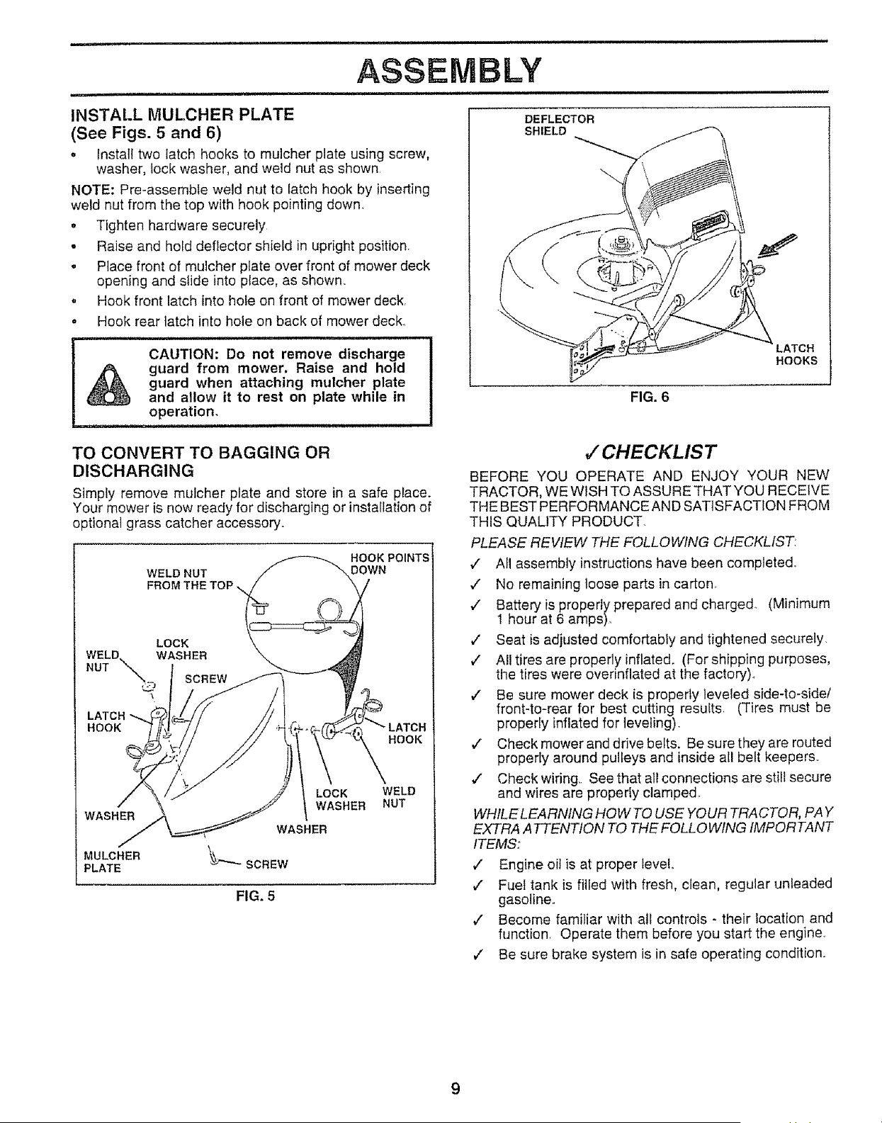
INSTALL MULCHER PLATE
(See Figs. 5 and 6)
o Install two latch hooks to mulcher plate using screw,
washer, lock washer, and weld nut as shown
NOTE: Pre-assemMe weld nut to latch hook by inserting
weld nut from the top with hook pointing down,
• Tighten hardware securely
° Raise and hold deflector shield in upright position,
o Place front of mulcher plate over front of mower deck
opening and slide into place, as shown.
. Hook front latch into hole on front of mower deck,
• Hook rear latch into hole on back of mower deck_
............................................... ii,
CAUTION: Do not remove discharge
guard from mower, Raise and hold
guard when attaching mulcher plate
and allow it to rest on plate while in
operation.
DEFLECTOR
SHIELD
FIG. 6
HOOKS
TO CONVERT TO BAGGING OR
DISCHARGING
Simply remove mulcher plate and store in a safe place.
Your mower is now ready for discharging or installation of
optional grass catcher accessory.
WELD NUT
FROM
HOOK POINTS
DOWN
LOCK
WELD. WASHER
NUT _ I
I SCREW
LATCH_
HOOK LATCH
HOOK
WASHER
MULCHER
PLATE
LOCK
WASHER
WELD
NUT
FIG. 5
,/CHECKLIS T
BEFORE YOU OPERATE AND ENJOY YOUR NEW
TRACTOR, WE WISH TO ASSURE THAT YOU RECEIVE
THE BEST PERFORMANCE AND SATISFACTION FROM
THIS QUALITY PRODUCT.
PLEASE REVIEW THE FOLLOWING CHECKLIST:
v" All assembly instructions have been completed.
v" No remaining loose parts in carton,
,/ Battery is properly prepared and charged (Minimum
I hour at 6 amps),
v" Seat is adjusted comfortably and tightened securely
€" A!l tires are properly inflated. (For shipping purposes,
the tires were overinfiated at the factory)_
,/ Be sure mower deck is properly leveled side-to-side/
front-to-rear for best cutting results, (Tires must be
properly inflated for leveling).
,/ Check mower and drive betts. Be sure they are routed
properly around pulleys and inside all belt keepers,,
,/ Check wiring. See that all connections are still secure
and wires are properly clamped
WHILE LEARNING HOW TO USE YOUR TRACTOR, PAY
EXTRA A TTENTION 70 THE FOLLO WING IMPORTANT
ITEMS:
¢' Engine oit is at proper level
,/ Fuel tank is filled with fresh, clean, regular unleaded
gasoline,,
€" Become familiar with all controls - their location and
function Operate them before you start the engine.
,/ Be sure brake system is in safe operating condition.

OPERATIO
These symbols may appear on your tractor or in literature supplied with the producL Learn and understand their meaning
BATTERY
ENGINE ON
REVERSE
CAUTION OR FORWARD SLOW
WARNING
ENGINE OFF OIL PRESSURE CLUTCH LIGHTS OFF
,,e,
FAST
LIGHTS ON
FUEL
X
CHOKE
MOWER HEIGHT DIFFERENTIAL PARKING BRAKE UNLOCKED
LOCK LOCKED
MOWER LIFT
REVERSE NEUTRAL
ATTACHMENT
CLUTCH ENGAGED
N L o;!
HIGH LOW PARKING BRAKE
÷
ATTACHMENT
CLUTCH DISENGAGED
IGNITION
DANGER, KEEP HANDS AND FEET AWAY
HYDROSTATIC FREE WHEEL
(Hydro Modelsonly)
10
i in, I III
OPERATION
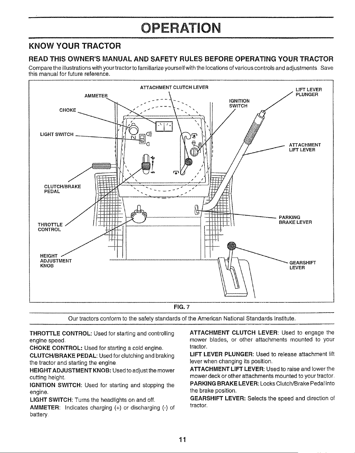
KNOW YOUR TRACTOR
READ THIS OWNER'S MANUAL AND SAFETY RULES BEFORE OPERATING YOUR TRACTOR
Compare the illustrations with your tractor to familiarize yourself with the locations of various controls and adjustments Save
this manual for future reference.,
CHOKE
LIGHT SWITCH
CLUTC_BRAKE
PEDAL
THROTTLE
CONTROL
AMMETER
ATTACHMENT CLUTCH LEVER
IGNITION
SWITCH
LIFT LEVER
PLUNGER
ATTACHMENT
LIFT LEVER
PARKING
BRAKELEVER
HEIGHT
ADJUSTMENT
KNOB
-,GEARSHIFT
LEVER
FIG. 7
Our tractors conform to the safety standards of the American National Standards Institute.
THROTTLE CONTROL: Used for starting and controlling
engine speed.
CHOKE CONTROL: Used for starting a cold engine..
CLUTCH/BRAKE PEDAL: Used for clutching and braking
the tractor and starting the engine
HEIGHT ADJ USTMENT KNOB: Used to adjust the mower
cutting height.
IGNITION SWITCH: Used for starting and stopping the
engine_
LIGHT SWITCH: Turns the headlights on and off.
AMMETER: Indicates charging (+) or discharging (-) of
battery
ATrACHMENT CLUTCH LEVER: Used to engage the
mower blades, or other attachments mounted to your
tractor,
LIFT LEVER PLUNGER: Used to release attachment lift
lever when changing its position,
ATTACHMENT LIFT LEVER: Used to raise and lower the
mower deck or other attachments mounted to your tractor.
PARKING BRAKE LEVER: Locks Clutch/Brake Pedal into
the brake positiOn.r
GEARSHIFT LEVER: Selects the speed and direction of
tractor_
11
Uq"Hli,,i, "hi ,,, U
OPERATAON
lUU ,H,,UlU ,, , i
i ,,111 ...................... i
The operation of any tractor can result in foreign objects thrown into the eyes, which
can result in severe eye damage. Always wear safety glasses or eye shields while
operating your tractor or performing any adjustments or repairs. We recommend a
wide vision safety mask over the spectacles or standard safety glasses,
........................... i, i, i i1,, nUll,
HOW TO USE YOUR TRACTOR
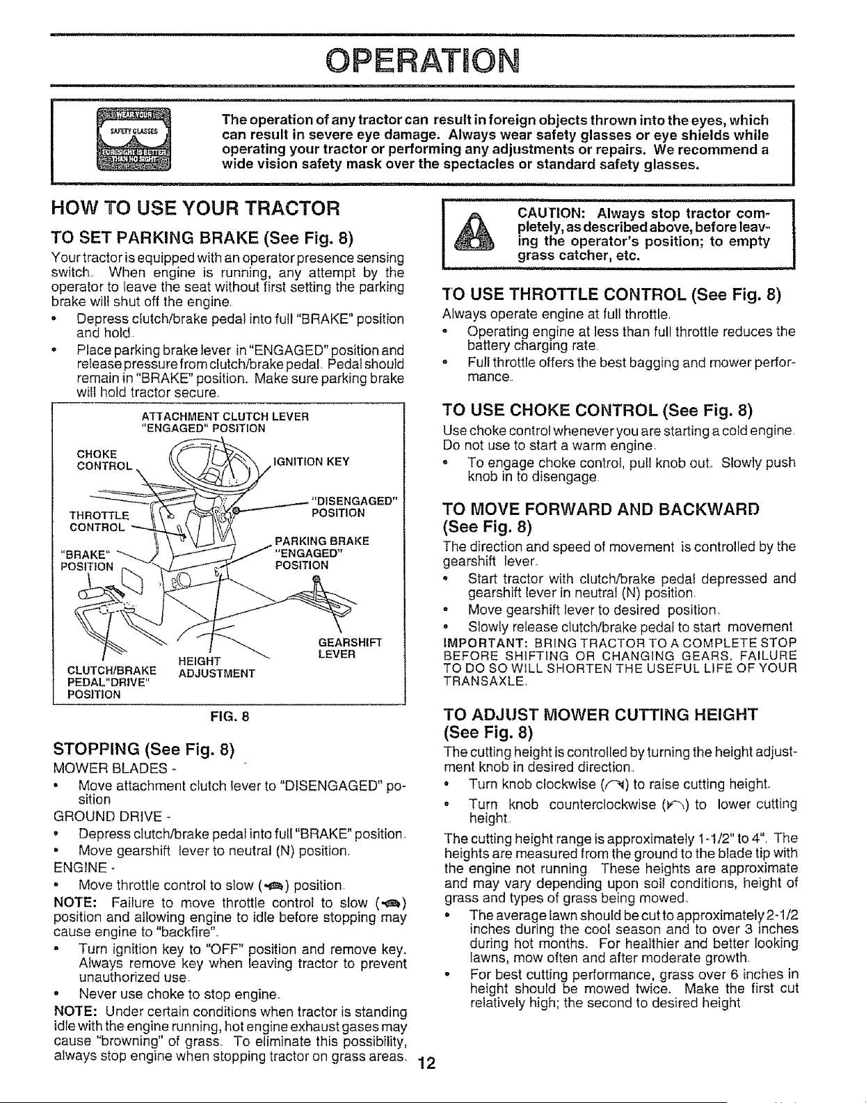
TO SET PARKING BRAKE (See Fig. 8)
Your tractor is equipped with an operator presence sensing
switch., When engine is running, any attempt by the
operator to ieave the seat without first setting the parking
brake wilt shut off the engine,
• Depress clutch/brake pedal into full "BRAKE" position
and hold,
• Place parking brake lever in "ENGAGED" position and
release pressu re from dutch/brake pedal Pedal should
remain in "BRAKE" position,, Make sure parking brake
will hold tractor secure.,
ATTACHMENT CLUTCH LEVER
_'ENGAGED" POSITION
CHOKE
CONTROL IGNITION KEY
THROTTLE
CONTROL
"BRAKE"
POSITION
_IGAGED"
POSITION
POSITION
CLUTCHfBRAKE
PEDAL"DRIVE"
POSITION
HEIGHT
ADJUSTMENT
GEARSHIFT
LEVER
FIG. 8
STOPPING (See Fig. 8)
MOWER BLADES -
• Move attachment clutch lever to "DISENGAGED" po-
sition
GROUND DRIVE -
• Depress clutch/brake pedal into full "BRAKE" position.
. Move gearshift lever to neutral (N) position,
ENGINE
- Move throttle control to slow (,_m_)position
NOTE: Failure to move throttle control to slow (_)
position and allowing engine to idle before stopping may
cause engine to "backfire".
. Turn ignition key to "OFF" position and remove key.
Always remove key when leaving tractor to prevent
unauthorized use.
° Never use choke to stop engine.
NOTE: Under certain conditions when tractor is standing
idle with the engine running, hot engine exhaust gases may
cause "browning" of grass,, To eliminate this possibility,
always stop engine when stopping tractor on grass areas, 12
CAUTION: Always stop tractor com-
pletely, as described above, before leav-
ing the operator's position; to empty
grass catcher, etc.
"['O USE THROTTLE CONTROL (See Fig. 8)
Always operate engine at full throttle,
- Operating engine at less than full throttle reduces the
battery charging rate.
o Full throttle offers the best bagging and mower perfor-
mance..
TO USE CHOKE CONTROL (See Fig. 8)
Use choke control whenever you are starting a cold engine,
Do not use to start a warm engine,
o To engage choke control, pull knob out, Slowly push
knob in to disengage
TO MOVE FORWARD AND BACKWARD
(See Fig. 8)
The direction and speed of movement is controlled by the
gearshift lever,
o Start tractor with clutch/brake pedal depressed and
gearshift lever in neutral (N) position
- Move gearshift lever to desired position,
o Slowly release clutch/brake pedal to start movement
IMPORTANT: BRING TRACTOR TO A COMPLETE STOP
BEFORE SHIFTING OR CHANGING GEARS, FAILURE
TO DO SO W_LL SHORTEN THE USEFUL LIFE OF YOUR
TRANSAXLE.
TO ADJUST MOWER CUTTING HEIGHT
(See Fig. 8)
The cutting height is controlled by turning the height adjust-
ment knob in desired direction,,
- Turn knob clockwise (F_I) to raise cutting heighL
= Turn knob counterclockwise (F_,) to lower cutting
height,
The cutting height range is approximately 1-1/2" to 4", The
heights are measured from the ground to the blade tip with
the engine not running These heights are approximate
and may vary depending upon sol! conditions, height of
grass and types of grass being mowed,
. The average lawn should be cut to approximately 2-1/2
inches during the coot season and to over 3 inches
during hot months. For healthier and better looking
lawns, mow often and after moderate growth,
. For best cutting performance, grass over 6 inches in
height should be mowed twice. Make the first cut
relatively high; the second to desired height
OPERATmON
,i ,i,1,,,,,ml ii, Ul,, H
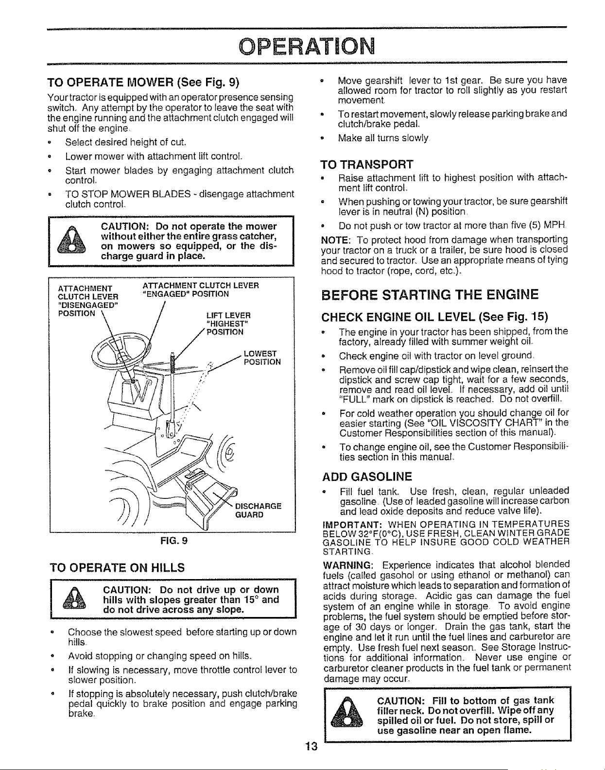
TO OPERATE MOWER (See Fig. 9) . Move gearshift lever to 1st gear. Be sure you have
allowed room for tractor to roll slightty as you restart
Your tractor is equipped with an operator presence sensing movement,
switch. Any attempt by the operator to leave the seat with
the engine running and the attachment clutch engaged will • To restart movement, slowly release parking brake and
shut off the engine, clutch/brake pedal.,
o Select desired height of cut. ° Make all turns slowly
• Lower mower with attachment lift control.
o Start mower blades by engaging attachment clutch TO
control. "
- TO STOP MOWER BLADES - disengage attachment
clutch control
i iiiiii
CAUTION: Do not operate the mower
without either the entire grass catcher,
on mowers so equipped, or the dis-
charge guard in place.
ATTACHMENT CLUTCH LEVER
"ENGAGED" POSITION
LIFI" LEVER
"HIGHEST"
- LOWEST
.._ POSITION
DISCHARGE
GUARD
FIG. 9
TO OPERATE ON HILLS
i, UUUll, iiim, i i i
°°"°''"ve °r"°wnI
hills with slopes greater than 15 ° and
do not drive across any slope.
o
o
e
Choose the slowest speed before starting up or down
hills
Avoid stopping or changing speed on hills.
If slowing is necessary, move throttle control lever to
slower position.
If stopping is absolutely necessary, push clutch/brake
pedal quickly to brake position and engage parking
brake.
!3
TRANSPORT
Raise attachment lift to highest position with attach-
ment lift control.
, When pushing or towing your tractor, be sure gearshift
lever is in neutral (N) position
, Do not push or tow tractor at more than five (5) MPH
NOTE: To protect hood from damage when transporting
your tractor on a truck or a trailer, be sure hood is closed
and secured to tractor. Use an appropriate means of tying
hood to tractor (rope, cord, etc.).
BEFORE STARTING THE ENGINE
CHECK ENGINE OIL LEVEL (See Fig. 15)
,, The engine in your tractor has been shipped, from the
factory, already filled with summer weight oil
o Check engine oil with tractor on level ground,
. Remove oil fill cap/dipstick and wipe clean, reinsert the
dipstick and screw cap tight, wait for a few seconds,
remove and read oil level If necessary, add oil until
"FULL" mark on dipstick is reached. Do not overfill..
, For cold weather operation you should change oil for
easier starting (See "OIL VISCOSITY CHART" in the
Customer Responsibilities section of this manual).
o To change engine oil, see the Customer Responsibili-
ties section in this manual.
ADD GASOLINE
° Fill fuel tank,, Use fresh, clean, regular unleaded
gasoline (Use of leaded gasoline will increase carbon
and lead oxide deposits and reduce valve life).
IMPORTANT: WHEN OPERATING iN TEMPERATURES
BELOW 32°F(0°C), USE FRESH, CLEAN WINTER GRADE
GASOLINE TO HELP iNSURE GOOD COLD WEATHER
STARTING.
WARNING: Experience indicates that alcohol blended
fuels (called gasohot or using ethanol or methanol) can
attract moisture which leads to separation and formation of
acids during storage. Acidic gas can damage the fuet
system of an engine while in storage To avoid engine
problems, the fuel system should be emptied before stor-
age of 30 days or longer,, Drain the gas tank, start the
engine and let it run until the fuel lines and carburetor are
empty. Use fresh fuel next season,, See Storage Instruc -
tions for additional information. Never use engine or
carburetor cleaner products in the fuel tank or permanent
damage may occur,
u,L ,,uluuJ_u_ _wl,u_ ill iI if
CAUTION: Fill to bottom of gas tank
filler neck. Do not overfill. Wipe off any
spilled oil or fuel. Do not store, spilt or
use gasoline near an open flame.
OPERATION
TO START ENGINE (See Fig. 8)
When starting engine for the first time or if engine has run
out of fuel, it will take extra cranking time to move fuel from
the tank to the engine
o Depress clutch/brake pedal and set parking brake
. Place gearshift lever in neutral (N) position,
• Move attachment clutch to "DISENGAGED" position.
° Pull choke control out to choke (N) position for cold
engine start, For warm engine start do not use choke
control
o Move throttle control to midway between fast (,@) and
slow (,_) positions.
o Insert key into ignit!on and turn key clockwise to"START"
position and release key as soon as engine starts. Do
not run starter continuously for more than fifteen
seconds per minute. If engine does not start after
several attempts, move throttle control to fast (,t_)
position, wait a few minutes and try again_
, When engine starts, slowly push choke control in.
o Move throttle control to fast (,_) position..
o Allow engine to warm up for a few minutes before
engaging drive or attachments.
NOTE: If at a high altitude (above 3000 feet) or in cold
temperatures (below 32°F), the carburetor fuel mixture
may need to be adjusted for best engine performance. See
"TO ADJUST CARBURETOR" in the Service and Adjust-
ments section of this manual.
MOWING TiPS
= Tire chains cannot be used when the mower housing
is attached to tractor.
* Mower should be properly leveled for best mowing
performance. See "TO LEVEL MOWER HOUSING" in
the Service and Adjustments section of this manual.
° The left hand side of mower should be used for trim-
ming
o Drive so that clippings are discharged onto the area
that has been cut. Have the cut area to the right of the
machine. This will result in a more even distribution of
clippings and more uniform'cutting
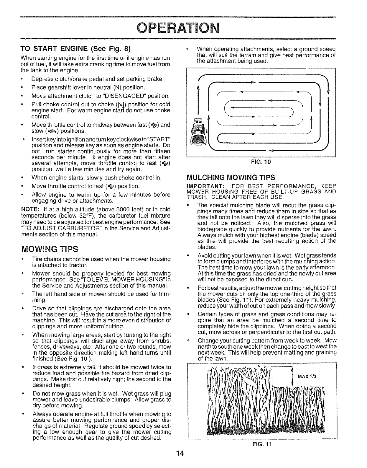
, When mowing large areas, start by turning to the right
so that clippings will discharge away from shrubs,
fences, driveways, etc. After one or two rounds, mow
in the opposite direction making left hand turns until
finished (See Fig. 10 ).
o If grass is extremely tall, it should be mowed twice to
reduce load and possible fire hazard from dried clip-
pings. Make first cut relatively high; the second to the
desired height..
o Do not mow grass when it is wet. Wet grass will plug
mower and leave undesirable clumps. Allow grass to
dry before mowing.
o Always operate engine at ful! throttle when mowing to
assure better mowing performance and proper dis-
charge of material Regulate ground speed by select-
ing a low enough gear to give the mower cutting
performance as welt as the quality of cut desired
o When operating attachments, select a ground speed
that will suit the terrain and give best performance of
the attachment being used°
C
iL,,,J
FIG. 10
MULCHING MOWING TIPS
IMPORTANT: FOR BEST PERFORMANCE, KEEP
MOWER HOUSING FREE OF BUILT-UP GRASS AND
TRASH CLEAN AFTER EACH USE
• The special mulching blade will recut the grass clip-
pings many times and reduce them in size so that as
they fall onto the lawn they will disperse into the grass
and not be noticed Also, the mulched grass will
biodegrade quickly to provide nutrients for the lawn.
Always mulch with your highest engine (blade) speed
as this will provide the best recutting action of the
blades.
o Avoid cutting you rlawn when it is wet. Wet grass tends
to form clumps and interferes with the mulching action
The best time to mow your lawn is the early afternoon.
At this time the grass has dried and the newly cut area
will not be exposed to the direct sun.
,, For best results, adjust the mower cutting height so that
the mower cuts off only the top one-third of the grass
blades (See Fig. 11)o For extremely heavy mulching,
reduce your width of cut on each pass and mow slowly
- Certain types of grass and grass conditions may re-
quire that an area be mulched a second time to
completely hide the ctippings. When doing a second
cut, mow across or perpendicular to the first cut path_
o Change your cutting pattern from week to week. Mow
no rth to south one week then change to east to west the
next week. This will help prevent matting and graining
of the lawn.
_1 MAX It3
FIGo 11
14
.................. i i1,11, ,lU,,,ll,,llll,,U,,
CUSTOMER RESPONSIBILITmES
j i , ilU.i iiiiiillll, i iii ,lllll.ll.Ulmllll..
_M'AINTENANCE SCHEDULE ..... J__o_ _0_I _"
AS YOU COMPLETE 0 _"_ R- R- R, _ R, 0
sERV,CE
i
--_e (3pera[i0n
h_eck Tire Pressure 6#4
T I Check for Loose Fasteners
R Shaken/ReplaceMower Btad'es
cA Lubrication Chart '........
T Check Battery LeveVRecharge
0 Clean Battery and Terminals
a CheckTransaxle Cooting
Adjust Blade Belt(s) Tension
Adjust Motion Drive Belt(s) Tension
Check Engine Oil Level
Change Engine Oil _#'
Clean Air Filter
E
N Clean Air,Screen
G Inspect MuffiedSparkArrester
| Replace Oil Filter (If equipped)
Clean Engine Cooling'Fins .........
Replace Spark Plug
Replace Air Filter Paper Cartridge
Replace Fuel Filter
V'7 v'
v'4
v' v'
v'
.... ,. ,,. ,,,_1_5 ...._.,.L, i
....... _1,2,3
V'2
e"
V'
1 - Change more often when operating under a heavy [oad or in high ambient temperatures
2 - Service more often when operating in dirty or dusty conditions
3 - If equipped with o_ifilter, change oil every 50 hours
4 - Replace blades more often when mowing in sandy soil
J
. I
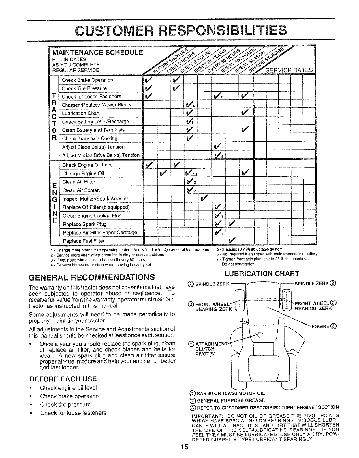
GENERAL RECOMMENDATIONS
The warranty on this tractor does not cover items that have
been subjected to operator abuse or negligence, To
receive full value from the warranty, operator must maintain
tractor as instructed in this manual.
Some adjustments will need to be made periodically to
properly maintain your tractor,
All adjustments in the Service and Adjustments section of
this manual should be checked at least once each season
o Once a year you should replace the spark plug, clean
or replace air filter, and check blades and belts for
wear° A new spark plug and clean air filter assure
proper air-fuel mixture and help your engine run better
and last [onger.
v' t .....
(_) SPINDLE
(_ FRONT
BEARING ZERK
(9
CLUTCH
PIVOT(S)
5 - If equipped wilh adjustable system
6 _ Not required if equ}pped with maintenance4ree battery
7 - T_ghlen front axle pivot bolt Io 35 ft -Ibs maximum
Do not overtighten
LUBRICATION CHART
IDLE ZERK(_)
FRONT WHEEL(_)
BEARING ZERK
ENGINE(_)
BEFORE EACH USE
. Check engine oil level,
- Check brake operation.,
o Check tire pressure.
. Check for loose fasteners.
15
L
(_SAE 30 OR 10W30 MOTOR OIL
(_) GENERAL PURPOSE GREASE
(_) REFER TO CUSTOMER RESPONSIBILITIES "ENGINE" SECTION
IMPORTANT: DO NOT OIL OR GREASE THE PIVOT POINTS
WHICH HAVE SPECIAL NYLON BEARINGS VISCOUS LUBRI-
CANTS WILL ATTRACT DUST AND DIRT THAT WILL SHORTEN
THE LIFE OF THE SELF-LUBRICATING BEARINGS, IF YOU
FEEL THEY MUST BE LUBRICATED, USE ONLY A DRY, POW-
DERED GRAPHITE TYPE LUBRICANT SPARINGLY

CUSTO RESPON BmLIT ES
........................................ ii ii, ,i, ,111ii ii
TRACTOR
Always observe safety rules when performing any mainte-
nance
BRAKE OPERATION
If tractor requires more than six (6) feet stopping distance
at high speed in highest gear, then brake must be adjusted.
(See "TO ADJUST BRAKE" in the Service and Adjust-
ments section of this manual).
TIRES
o Maintain proper air pressure in all tires (See "PROD-
UCT SPECIFICATIONS on page 3 of this manuat)_
o Keep tires free of gasoline, oil, or insect control chemi-
cals which can harm rubber..
. Avoid stumps, stones, deep ruts, sharp objects and
other hazards that may cause tire damage.
TO SHARPEN BLADE (See Fig. 13)
Care should be taken to keep the blade balanced. An
unbalanced blade will cause excessive vibration and even-
tual damage to mower and engine.
, The blade can be sharpened with a file or on a grinding
wheel. Do not attempt to sharpen while on the mower
° To check blade balance, you will need a 5/8" diameter
steel bolt, pin, or a cone balancero (When using a cone
bafancer, follow the instructions supplied with bat-
ancer).
o Slide blade on to an unthreaded portion of the steel bolt
or pin and hold the bolt or pin parallel with the ground.
If blade is balanced, it should remain in a horizontal
position., tf either end of the blade moves downward,
sharpen the heavy end until the blade is balanced,.
NOTE: Do not use a nail for balancing blade. The lobes of
the center hole may appear to be centered, but are not.
BLADE CARE
For best results mower blades must be kept sharp, Re-
place bent or damaged blades..
BLADE REMOVAL (See Fig. 12)
= Raise mower to highest position to allow access to
blades,,
• Remove hex bolt, lock washer and fiat washer securing
blade
, Install new or resharpened blade with trailing edge up
towards deck as shown,
, Reassemble hex bolt, lock washer and flat washer in
exact order as shown.
o Tighten bolt securely (30-35 Ft Lbs, torque).
IMPORTANT: BLADE BOLT IS GRADE 8 HEAT TREATED
NOTE: We do not recommend sharpening blade- but ifyou
do, be sure the blade is balanced.
MANDREL
ASSEMBLY
FLAT WASHER
_._ BLADE
LOCK WASHER _.'_-._,- _TRAILING EDGE
'A GRADE 8 HEAT TREATED BOLT CAN BE IDENTIFIED
BY SIX LINES ON THE BOLT HEAD.
FIG. 12
,/
CENTER _""_'C <_"
FIG. 13
BATTERY
Your tractor has a battery charging system which is suffi-
cient for normal use° However, periodic charging of the
battery with an automotive charger will extend its life.
• Keep battery and terminals clean..
o Keep battery bolts tight.
o Keep small vent holes open.
. Recharge at 6-10 amperes for I hour.
TO CLEAN BATTERY AND TERMINALS
Corrosion and dirt on the battery and terminals can cause
the battery to "leak" power.
= Remove terminal guard.
. Disconnect BLACK battery cable first then RED bat-
tery cable and remove battery from tractor.
= Rinse the battery with plain water and dry
° Clean terminals and battery cable ends with wire brush
until brighL
• Coat terminals with grease or petroleum jelly
o Reinstall battery (See "CONNECT BATTERY" in the
Assembly section of this manual).
16
i,iiii i i ill
,iu,ill
i i illll i,ill,llll ..................................... i llllll,
CUSTOMER RESPONSIBULITUES
ii ,i ii,ll,lllllll,lll
V-BELTS
Check V-belts for deterioration and wear after100 hours of
operation and replace if necessary_ The belts are not
adjustable,, Replace belts if they begin to slip from wear.
TRANSAXLE COOLING
Keep transaxle free from buifd-up of dirt and chaff which
can restrict coolingo
ENGINE
LUBRICATION
Only use high quality detergent oil rated with API service
classification SF or SG.. Select the oil's SAE viscosity
grade according to your expected operating temperature
SAE VISCOSITY GRADES
°F -2o° o° _o" 32° 4d_ soo _oo i_o;--
°c -doo .20° .18o oo l'oo _0o =oo !0:
TEMPERATURE RANGE ANTICIPATED BEFORE NEXT OIL CHANGE
NOTE: Although multi-viscosity oils (5W30, 10W30 etco)
improve starting in cold weather, these multi-viscosity oils
wi{l result in increased oil consumption when used above
32°F. Check your engine oi] level more frequently to avoid
possible engine damage from running low on oil.
Change the oil after the first two hours of operation and
every 25 hours thereafter or at least once a year if the
tractor is not used for 25 hours in one year.
Check the crankcase oil level before starting the engine
and after each eight (8) hours of operation. Tighten oil fill
cap/dipstick securely each time you check the oil IeveL
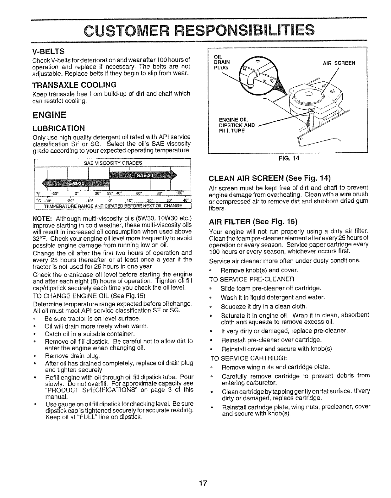
TO CHANGE ENGINE OIL (See Fig.15)
Determine temperature range expected before oil change.
Alf oil must meet AP1 service classification SF or SGo
, Be sure tractor is on level surface.
o Oil will drain more freely when warm.
o Catch oil in a suitable container.
° Remove oit fill dipstick° Be careful not to aIIow dirt to
enter the engine when changing oil.
o Remove drain plug.
, After oil has drained completely, replace oil drain p{ug
and tighten securely.
o Refill engine with oil through oil fill dipstick tube. Pour
slowty. Do not overfill. For approximate capacity see
"PRODUCT SPECIFICATIONS" on page 3 of this
manual.
o Use gauge on oil fill dipstick for checking level Be sure
dipstick cap is tightened securely for accurate reading.
Keep oil at "FULL" line on dipstick.
OIL
DRAIN
PLUG
AIR SCREEN
ENGINE OIL
DIPSTICK AND
FILL TUBE
FIG, 14
CLEAN AIR SCREEN (See Fig. 14)
Air screen must be kept free of dirt and chaff to prevent
engine damage from overheating_ Clean with a wire brush
or compressed air to remove dirt and stubborn dried gum
fibers.
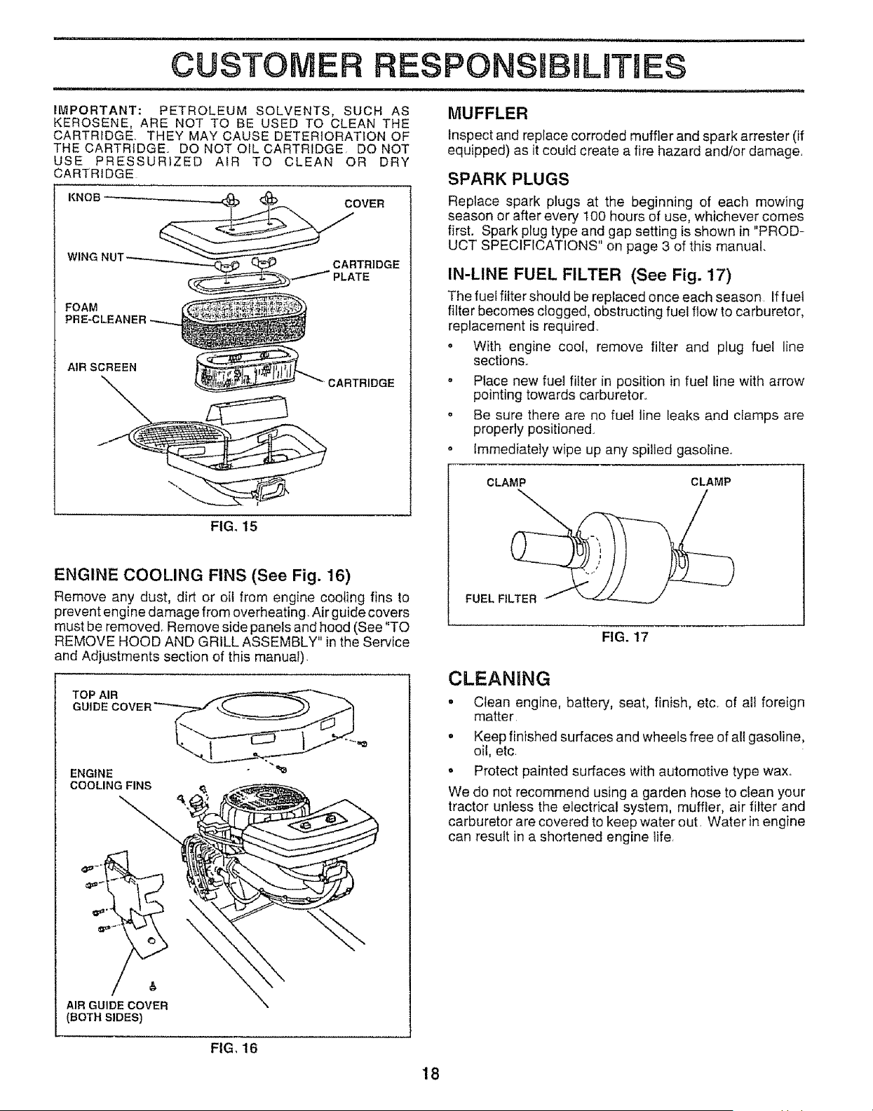
AIR FILTER (See Fig. 15)
Your engine will not run properly using a dirty air filter_
Clean the foam pre-cleaner element after every 25 hours of
operation or every season. Service paper cartridge every
100 hours or every season, whichever occurs first.
Service air cleaner more often under dusty conditions.
- Remove knob(s) and cover_
TO SERVlCE PRE-CLEANER
, Slide foam pre-cleaner off cartridge.
o Wash it in liquid detergent and water
o Squeeze it dry in a clean cloth.
• Saturate it in engine oil Wrap it in clean, absorbent
cloth and squeeze to remove excess oil.
• if very dirty or damaged, replace pre-cleaner.
• Reinstall pre-cleaner over cartridge.
o Reinstall cover and secure with knob(s)
TO SERVICE CARTRIDGE
° Remove wing nuts and cartridge plate.
= Carefully remove cartridge to prevent debris from
entering carburetor.
° Clean cartridge by tapping gently on flat surface. If very
dirty or damaged, replace cartridge.
• Reinstall cartridge plate, wing nuts, precleaner, cover
and secure with knob(s)
17
CUSTO RESPONSDBmL TIE
IMPORTANT: PETROLEUM SOLVENTS, SUCH AS
KEROSENE, ARE NOT TO BE USED TO CLEAN THE
CARTRIDGE THEY MAY CAUSE DETERIORATION OF
THE CARTRIDGE DO NOT OIL CARTRIDGE DO NOT
USE PRESSURIZED AIR TO CLEAN OR DRY
CARTRIDGE
FOAM
PRE-CLEANER
AIR SCREEN
FIG. 15
ENGINE COOLING FINS (See Fig. 16)
Remove any dust, dirt or oit from engine cooling fins to
prevent engine damage from overheating. Air guide covers
must be removed. Remove side panels and hood (See '*TO
REMOVE HOOD AND GRILL ASSEMBLY" in the Service
and Adjustments section of this manual)
TOP AIR
ENGINE
COOLING FINS
_4_ -" L._. _
/,
AIR GUIDE COVER
(BOTHSIDES)
FIG, 16
MUFFLER
Inspect and replace corroded muffler and spark arrester (if
equipped) as it could create a fire hazard and/or damage
SPARK PLUGS
Replace spark plugs at the beginning of each mowing
season or after every 100 hours of use, whichever comes
first. Spark plug type and gap setting is shown in "PROD-
UCT SPECIFICATIONS" on page 3 of this manual
IN-LINE FUEL FILTER (See Fig. 17)
The fuel filter should be replaced once each season Iffuel
filter becomes clogged, obstructing fuel flow to carburetor,
replacement is required.
o With engine cool, remove filter and plug fuel line
sections..
• Place new fuel filter in position in fuel line with arrow
pointing towards carburetor.
o Be sure there are no fuel line leaks and clamps are
properly positioned.
o Immediately wipe up any spilled gasoline°
CLAMP CLAMP
FUEL FILTER
FIG. 17
CLEANING
• Clean engine, battery, seat, finish, etc. of all foreign
matter
o Keep finished surfaces and wheels free of all gasoline,
oil, etc
• Protect painted surfaces with automotive type wax.
We do not recommend using a garden hose to clean your
tractor unless the electrical system, muffler, air filter and
carburetor are covered to keep water out Water in engine
can result in a shortened engine life.
18
=,,=,,,= ..................... =, , 'HH
SERVICE, AND ADJUSTMENTS
1,, i = 11
i ii, iiii _ ,M,I,
CAUTION: BEFORE PERFORMING ANY SERVICE OR ADJUSTMENTS:
= Depress clutchlbrake pedal fully and set parking brake.. Place gearshift lever in neutral (N) position.
o Place attachment clutch in "DISENGAGED" position.
• Turn ignition key "OFF" and remove key.
. Make sure the blades and all moving parts have completely stopped.
° Disconnect spark plug wire from spark plug and place wire where it cannot come in contact with
plug,
TRACTOR
CLUTCH LEVER
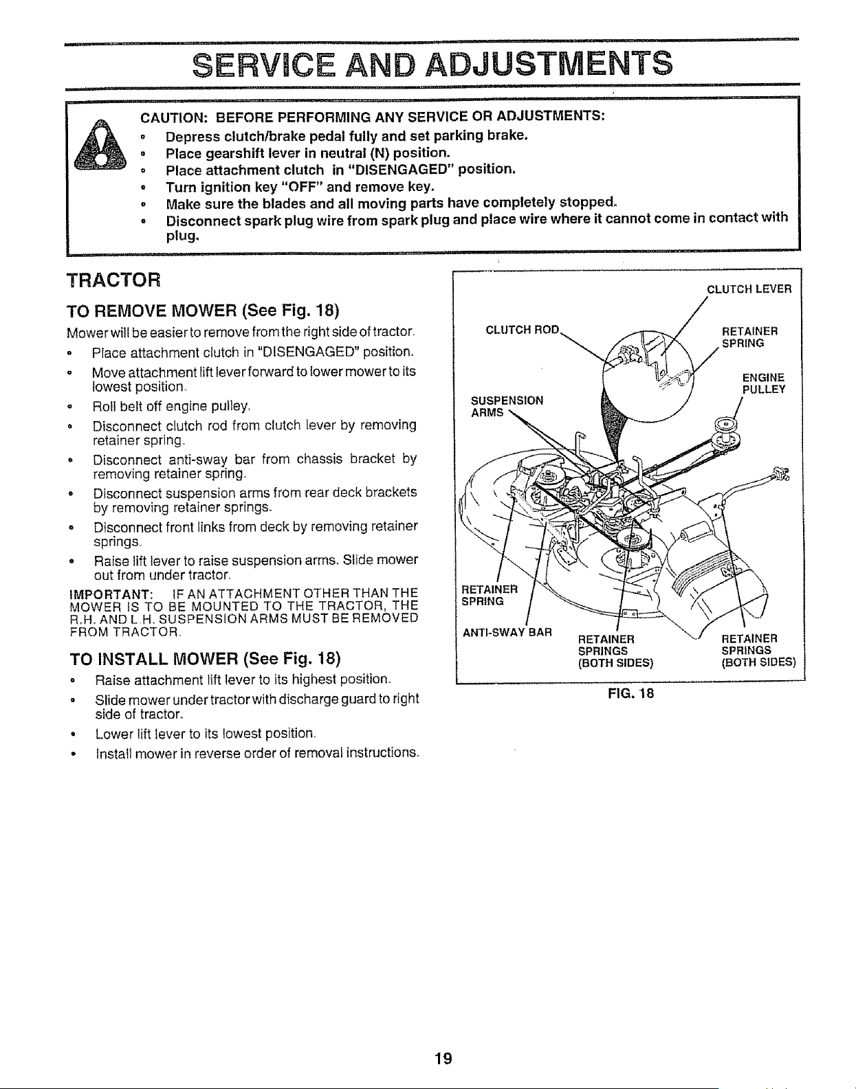
TO REMOVE MOWER (See Fig. 18)
Mower will be easier to remove from the right side of tractor.
o Place attachment clutch in "DISENGAGED" position,,
o Move attachment lift lever forward to Iower mower to its
!owest position°
o Roll bett off engine pulley,
° Disconnect clutch rod from clutch lever by removing
retainer spring,,
,, Disconnect antFsway bar from chassis bracket by
removing retainer spring.,
o Disconnect suspension arms from rear deck brackets
by removing retainer springs_
o Disconnect front links from deck by removing retainer
springs.,
• Raise lift lever to raise suspension arms. SNde mower
out from under tractor_
IMPORTANT: IF AN ATTACHMENT OTHER THAN THE
MOWER IS TO BE MOUNTED TO THE TRACTOR, THE
R.H, AND L,H. SUSPENSION ARMS MUST BE REMOVED
FROM TRACTOR.,
TO INSTALL MOWER (See Fig. 18)
o Raise attachment lift lever to its highest position°
• Slide mower under tractorwith discharge guardto right
side of tractor.
• Lower lift lever to its lowest position,.
• Install mower in reverse order of removal instructions_
Cl RETAINER
SPRING
SUSPENSION
ARMS
ENGINE
PULLEY
RETAINER
SPRING
ANTI-SWAY BAR
RETAINER RETAINER
SPRINGS SPR|NGS
(BOTH SIDES) (BOTH SIDES)
FIG. 18
19
SERVmCE AN
TO LEVEL MOWER HOUSING
Adjust the mower while tractor is parked on level ground or
driveway, Make sure tires are properly inflated (See
"PRODUCT SPECIFICATIONS" on page 3 of this manual).
If fires are over or underinfiated, you wilt not properly adjust
your mower
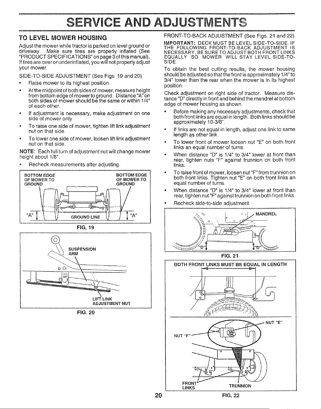
SIDE-TO-SIDE ADJUSTMENT (See Figs 19 and 20)
o
Raise mower to its highest position.
At the midpoint of both sides of mower, measure height
from bottom edge of mower to ground Distance"A" on
both sides of mower should be the same or within 1/4"
of each other.
o If adjustment is necessary, make adjustment on one
side of mower only
o To raise one side of mower, tighten lift link adjustment
nut on that side
° To lower one side of mower, loosen lift link adjustment
nut on that side.
NOTE: Each full turn of adjustment nut will change mower
height about 1/8"..
o Recheck measurements after adjusting.
BOTTOM EDGE BOTTOM EDGE
OF MOWER TO OF MOWER TO
GROUND GROUND
LIFT LINK
ADJUSTMENT NUT
FIG. 19
SUSPENSION
ARM
FIG. 20
ADJU ;TMENTS
i
FRONT-TO-BACK ADJUSTMENT (See Figs° 21 and 22)
IMPORTANT; DECK MUST BE LEVEL SIDE-TO-SIDE. iF
THE FOLLOWING FRONT-TO-BACK ADJUSTMENT IS
NECESSARY, BE SURE TO ADJUST BOTH FRONT LINKS
EQUALLY SO MOWER WILL STAY LEVEL SIDE-TO-
SIDE
To obtain the best cutting results, the mower housing
should be adjusted so that the front is app roximately 1/4" to
3/4" lower than the rear when the mower is in its highest
position°
Check adjustment on right side of tractor.. Measure dis-
tance "D" directly in front and behind the mandrel at bottom
edge of mower housing as shown
• Before making any necessary adjustments, check that
both front finks are equal in length. Both iinks should be
approximately 10-3f8".
• If links are not equal in length, adjust one tink to same
iength as other tink
o To lower front of mower loosen nut "E" on both front
links an equal number of turns
° When distance "D" is 1/4" to 3/4" lower at front than
rear, tighten nuts "F" against trunnion on both front
links.
o To raise front of mower, loosen nut "F" from trunnion on
both front links. Tighten nut "E" on both front links an
equal number of turns.
- When distance "D" is 1/4" to 3/4" lower at front than
rear, tighten nut"F" against trunnion on both front links.
o Recheck side-to-side adjustment.
:;_, % Io ,_o_ MANDREL
//;'/I --
-_ ,_ _ 4,'_" _
FIG. 21
BOTH FRONT LINKS MUST BE EQUAL IN LENGTH
,_ NUT "E"
l
LINKS TRUNNION
20 FIG. 22
i, i,u,lu ii ,,i,i,u,,
SERVNCE AND ADJUSTMENTS
i, nll,l,,i,,,mp ull
WITHPARKING BRAKE "ENGAGED"
, irll,l,q i¸ i,,,
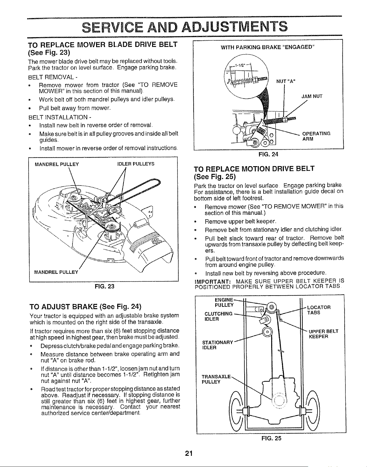
TO REPLACE MOWER BLADE DRIVE BELT
(See Fig. 23)
The mower blade drive belt may be replaced without toois_
Park the tractor on level surface, Engage parking brake.
BELT REMOVAL -
o Remove mower from tractor (See "TO REMOVE
MOWER" in this section of this manual)
- Work belt off both mandrel pulleys and idler pulleys.
• Pull belt away from mower.
BELT INSTALLATION -
• Install new belt in reverse order of removal
o Make sure belt is in all pulley grooves and inside all belt
guides.
• Install mower in reverse order of removal instructions.
NUT "A"
M NUT
ERATING
OL_ ARM
FIG, 24
MANDREL PULLEY
IDLER PULLEYS
/
MANDREL PULLEY
FIG, 23
TO REPLACE MOTION DRIVE BELT
(See Fig. 25)
Park the tractor on level surface Engage parking brake
For assistance, there is a belt installation guide decal on
bottom side of left footrest.
- Remove mower (See "TO REMOVE MOWER" in this
section of this manual.)
o Remove upper belt keeper,,
o Remove belt from stationary idler and clutching idler,
• Pull belt slack toward rear of tractor. Remove belt
upwards from transaxte pulley by deflecting belt keep-
ers.
° Pull belt toward front of tractor and remove downwards
from around engine pulley,
o Install new belt by reversing above procedure,,
IMPORTANT: MAKE SURE UPPER BELT KEEPER IS
POSITIONED PROPERLY BETWEEN LOCATOR TABS
TO ADJUST BRAKE (See Fig. 24)
Your tractor is equipped with an adjustable brake system
which is mounted on the right side of the transaxle
if tractor requires more than six (6) feet stopping distance
at high speed in highest gear, then brake must be adjusted
o Depress clutch/brake pedal and engage parking brake,.
. Measure distance between brake operating arm and
nut "A" on brake rod.
• If distance is other than 1-tt2", loosen jam nut and turn
nut "A" until distance becomes 1-1/2", Retighten jam
nut against nut "A",
o Road test tractor for proper stopping distance as stated
above. Readjust if necessary. If stopping distance is
still greater than six (6) feet in highest gear, further
maintenance is necessary, Contact your nearest
authorized service center/departmenL
ENGINE--,--.._
PULLEY
CLUTCHING_.,,,,
IDLER
STATIONARY /
IDLER
PULLEY
_........L_
_LOCATOR
FIG, 25
21
SERVICE AND ADJUSTMENTS
TO ADJUST STEERING WHEEL ALIGNMENT
If steering wheel crossbars are not horizontal (left to right)
when wheels are positioned straightforward, remove steer-
rng wheel and reassemble per instructions in the Assembly
section of this manuaL,
FRONT WHEEL TOE,,IN/CAMBER
The front wheel toe-in and camber are not adjustable on
your tractor,_ If damage has occurred to affect the front
wheel toe-in or camber, contact your nearest authorized
service center
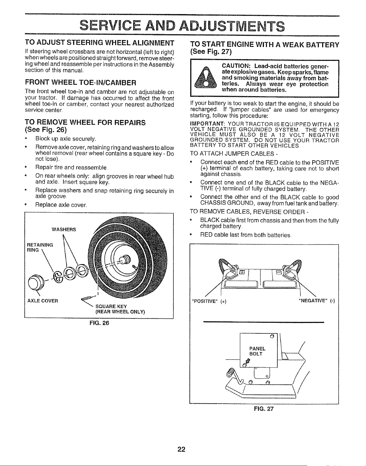
TO REMOVE WHEEL FOR REPAIRS
(See Fig. 26)
Block up axle securely,
o Remove axle cover, retaining ring and washers to allow
whee! removal (rear wheel contains a square key - Do
not {ose)
= Repair tire and reassemble
o On rear whee{s only: align grooves in rear wheel hub
and axle. Insert square key_
. Reptace washers and snap retaining ring securely in
axle groove.
o Replace axle cover.
WASHERS
RETAINING
RING
AXLE COVER
I
(REAR WHEEL ONLY)
FIG. 26
TO START ENGINE WITH A WEAK BATTERY
See Fig. 27)
,,,i,in,,ll i, lU,,, i, , u
CAUTION: Lead-acid batteries gener-
ate explosive gases, Keep sparks, flame
and smoking materials away from bat-
teries. Always wear eye protection
when around batteries.
.................. ii ll,i n, i
If your battery is too weak to start the engine, it should be
recharged, Lf "jumper cabies" are used for emergency
starting, follow this procedure:
IMPORTANT: YOUR TRACTOR IS EQUIPPED WITH A 12
VOLT NEGATIVE GROUNDED SYSTEM, THE OTHER
VEHICLE MUST ALSO BE A 12 VOLT NEGATIVE
GROUNDED SYSTEM. DO NOT USE YOUR TRACTOR
BATTERY TO START OTHER VEHICLES
TO ATi-ACH JUMPER CABLES -
• Connect each end of the RED cable to the POSITIVE
(+) terminal of each battery, taking care not to short
against chassis,
° Connect one end of the BLACK cable to the NEGA-
TIVE (-) terminal of fully charged battery..
• Connect the other end of the BLACK cable to good
CHASSIS GROUND, away from fuel tank and battery..
TO REMOVE CABLES, REVERSE ORDER -
° BLACK cable first from chassis and then from the fuf]y
charged battery.
o RED cable last from both batteries,
"POSITIVE" (+) "NEGATIVE"(-)
0
PANEL
BOLT
FIG. 27
22
..... , , nl,, iluu
SERVICE AND ADJUSTMENTS
,11 , i,,i,,, n,u,i
TO REPLACE HEADLIGHT BULB ENGINE
. Raise hood.
o Pull bulb holder out of the hole in the backside of the
grill
o Replace bulb in holder and push bulb holder securely
back into the hole in the backside of the grill.
- Close hood..
INTERLOCKS AND RELAYS
Loose or damaged wiring may cause your tractor to run
poorly, stop running, or prevent it from starting.
° Check wiring. See electrical wiring diagram in Repair
Parts section of this manual..
TO REPLACE FUSE
Replace with 30 amp automotive-type plug-in fuse. The
fuse holder is located behind the dash,
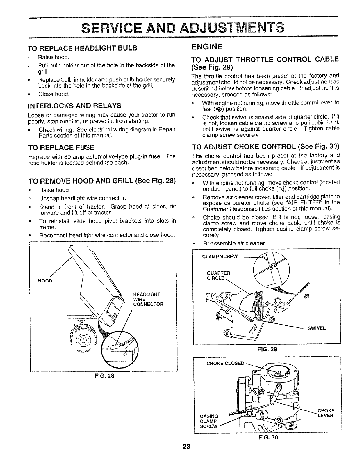
TO REMOVE HOOD AND GRILL (See Fig. 28)
o Raise hood
= Unsnap headlight wire connector.
. Stand in front of tractor, Grasp hood at sides, tilt
forward and lift off of tractor.
o To reinstall, slide hood pivot brackets into slots in
frame,
• Reconnect headlight wire connector and close hood.
HOOD
HEADLIGHT
WIRE
CONNECTOR
FIG. 28
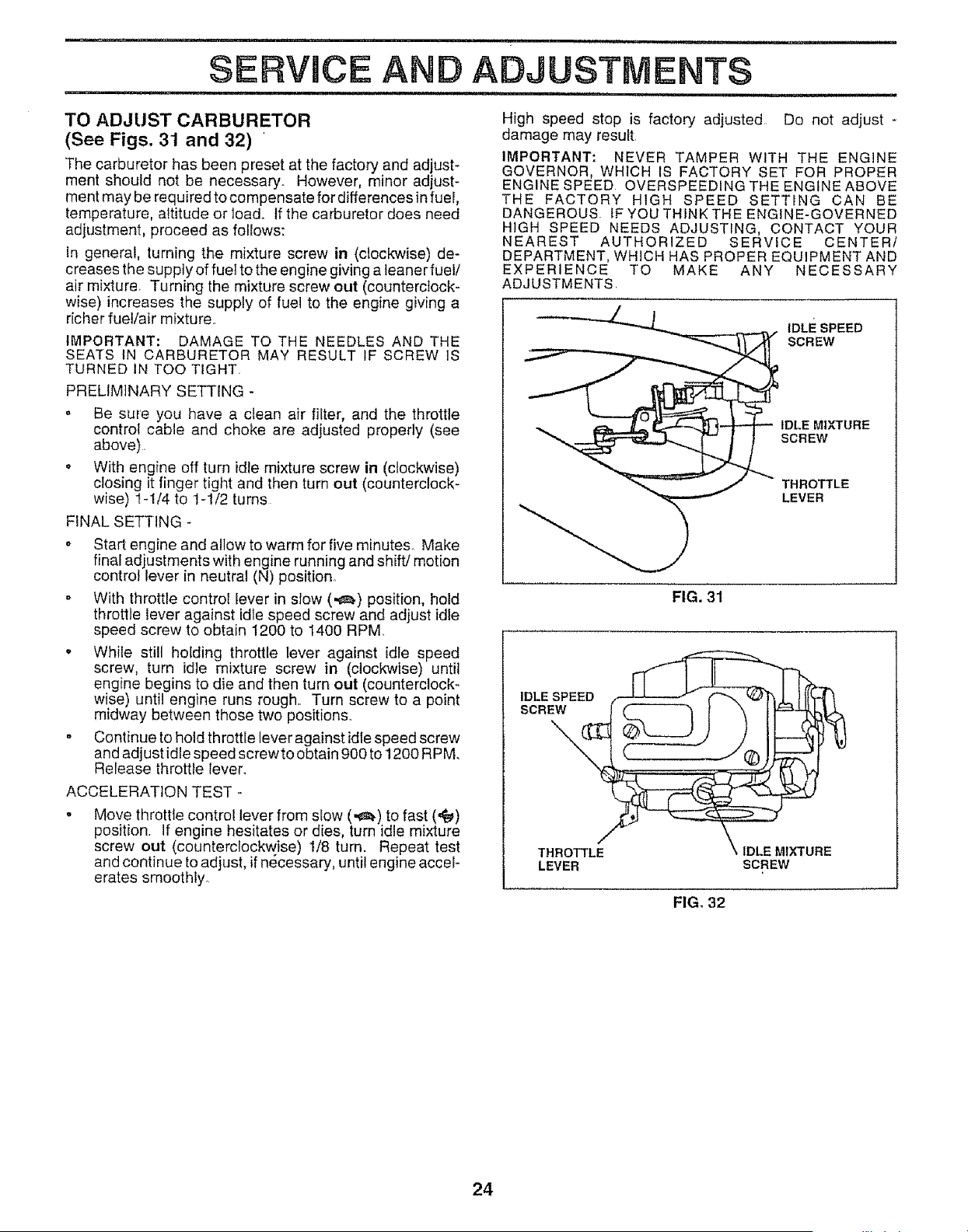
TO ADJUST THROTTLE CONTROL CABLE
(See Fig. 29)
The throttle control has been preset at the factory and
adjustment should not be necessary, Check adjustment as
descnbed below before loosening cable If adjustment is
necessary, proceed as follows:
o With engine not running, move throttle control lever to
fast (,_) position.
° Check that swivel is against side of quarter circle. If it
is not, loosen cable clamp screw and pull cable back
until swivel is against quarter circle Tighten cable
clamp screw securely.
TO ADJUST CHOKE CONTROL (See Fig. 30)
The choke control has been preset at the factory and
adjustment should not be necessary. Check adjustment as
described below before loosening cable, If adjustment is
necessary, proceed as follows:
o With engine not running, move choke control (located
on dash panel) to full choke (N) position,
o Remove air cleaner cover, filter and cartridge plate to
expose carburetor choke (see "AIR FILTER" in the
Customer Responsibilities section of this manual).
o Choke should be closed If it is not, loosen casing
clamp screw and move choke cable until choke is
completely closed Tighten casing clamp screw se-
curely,
= Reassemble air cleaner,
CLAMP SCREW
QUARTER
SWIVEL
FIG, 29
CHOKE CLOSED
CASING
CLAMP
SCREW I-_
CHOKE
LEVER
FIG. 30
23
SERVICE AN ADJUSTMENTS
TO ADJUST CARBURETOR
(See Figs. 31 and 32) '
The carburetor has been preset at the factory and adjust-
ment should not be necessary. However, minor adjust-
ment may be required to compensate for differences in fuel,
temperature, attitude or load. If the carburetor does need
adjustment, proceed as follows:
In general, turning the mixture screw in (clockwise) de-
creases the supply of fuet to the engine giving a leaner fuel/
air mixture Turning the mixture screw out (counterclock-
wise) increases the supply of fuel to the engine giving a
richer fuel!air mixture.
IMPORTANT: DAMAGE TO THE NEEDLES AND THE
SEATS IN CARBURETOR MAY RESULT IF SCREW IS
TURNED IN TOO TIGHT.
PRELIMINARY SETTING -
o Be sure you have a clean air filter, and the throttle
control cable and choke are adjusted properly (see
above).
o With engine off turn idle mixture screw in (clockwise)
closing it finger tight and then turn out (counterclock-
wise) I-1/4 to 1-1/2 turns
FINAL SETTING -
o Start engine and allow to warm for five minutes. Make
final adjustments with engine running and shift/motion
control lever in neutral (N) position.
- With throttle control lever in slow (,_) position, hold
throttle lever against idle speed screw and adjust idle
speed screw to obtain t200 to 1400 RPM
o While still holding throttle lever against idle speed
screw, turn idle mixture screw in (clockwise) until
engine begins to die and then turn out (counterclock-
wise) until engine runs rough. Turn screw to a point
midway between those two positions.
o Continue to hold throttle lever against idle speed screw
and adjust idle speed screwto obtain 900 to 1200 RPM.
Release throttle lever.
ACCELERATION TEST -
Move throttle control lever from slow (.e_) to fast ('#e_)
position. If engine hesitates or dies, turn idle mixture
screw out (counterclockwise) 1/8 turn. Repeat test
and continue to adjust, if nr_,cessary, until engine accel-
erates smoothly.
High speed stop is factory adjusted Do not adjust -
damage may result
IMPORTANT: NEVER TAMPER WITH THE ENGINE
GOVERNOR, WHICH IS FACTORY SET FOR PROPER
ENGINE SPEED OVERSPEEDING THE ENGINE ABOVE
THE FACTORY HIGH SPEED SETTING CAN BE
DANGEROUS. IF YOU THINK THE ENGINE-GOVERNED
HIGH SPEED NEEDS ADJUSTING, CONTACT YOUR
NEAREST AUTHORIZED SERVICE CENTER/
DEPARTMENT, WHICH HAS PROPER EQUIPMENT AND
EXPERIENCE TO MAKE ANY NECESSARY
ADJUSTMENTS
IDLE SPEED
SCREW
IDLE MIXTURE
SCREW
THROTTLE
LEVER
FIG. 31
THROTTLE
LEVER
IDLE MIXTURE
SCREW
FIG, 32
24
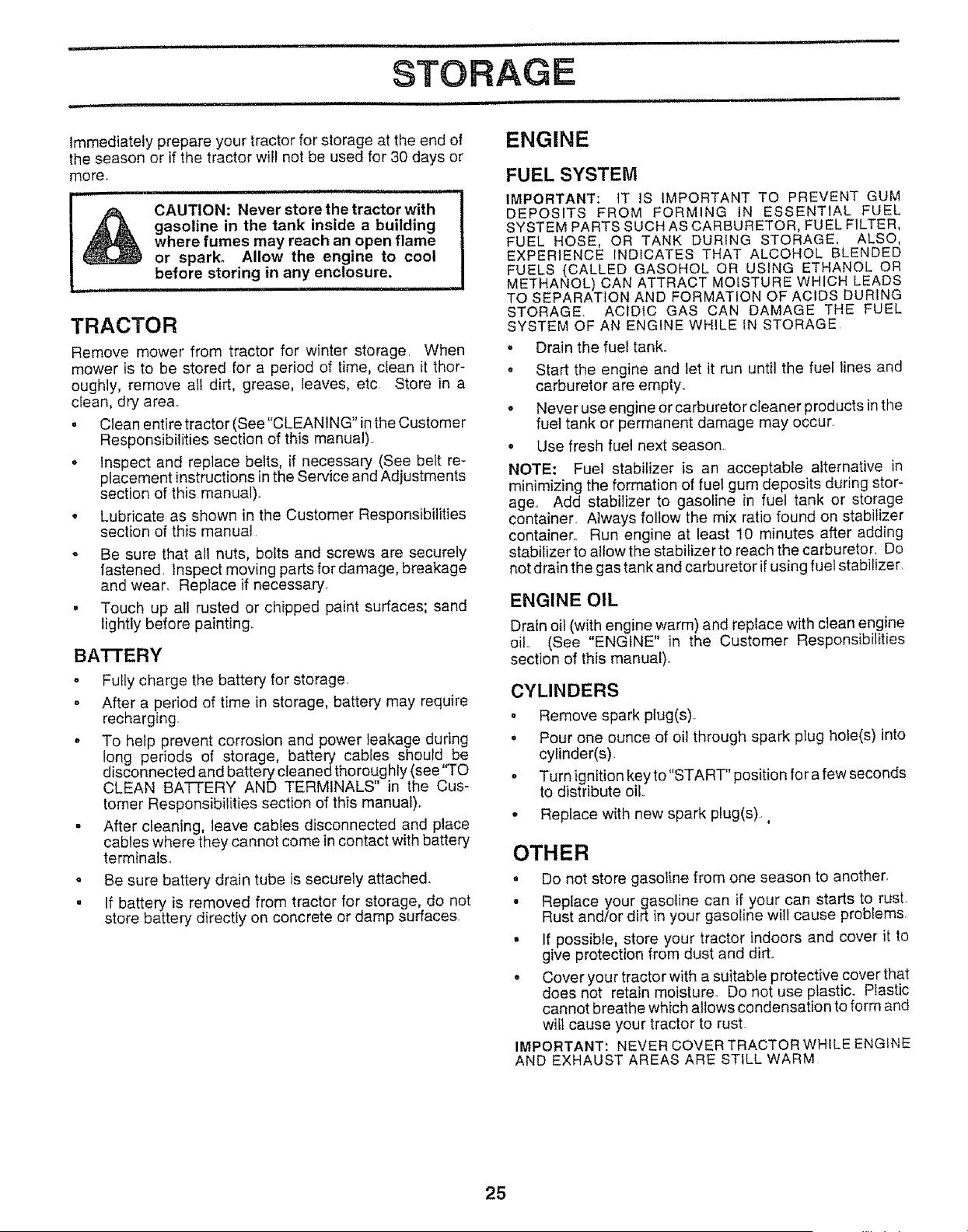
Immediately prepare your tractor for storage at the end of ENGINE
the season or if the tractor wilt not be used for 30 days or
more..
t& CAUTION: Never store the tractor with I
gasoline in the tank inside a building !
where fumes may reach an open flame i
or spark. Allow the engine to cool I
before storing in any enclosure. |
-I
TRACTOR
Remove mower from tractor for winter storage. When
mower is to be stored for a period of time, clean it thor-
oughly, remove nil dirt, grease, leaves, etc Store in a
clean, dry area..
. Clean entire tractor (See"CLEANING" in the Customer
Responsibilities section of this manual)
• Inspect and replace belts, if necessary (See belt re-
placement instructions in the Service and Adjustments
section of this manual).,
o Lubricate as shown in the Customer Responsibilities
section of this manual
• Be sure that all nuts, bolts and screws are securely
fastened. Inspect moving partsfordamage, breakage
and wear. Replace if necessary.
• Touch up all rusted or chipped paint surfaces; sand
lightly before painting.
BA'N'ERY
, Fully charge the battery for storage.
o After a period of time in storage, battery may require
recharging.
o To help prevent corrosion and power leakage during
long periods of storage, battery cables should be
disconnected and battery cleaned thoroughly (see''TO
CLEAN BATTERY AND TERMINALS" in the Cus-
tomer Responsibilities section of this manuaf)_
° After cleaning, leave cables disconnected and place
cables where they cannot come in contact with battery
terminals_
o Be sure battery drain tube is securely attached.
= If battery is removed from tractor for storage, do not
store battery directly on concrete or damp surfaces
FUEL SYSTEM
IMPORTANT: IT IS IMPORTANT TO PREVENT GUM
DEPOSITS FROM FORMING iN ESSENTIAL FUEL
SYSTEM PARTS SUCH AS CARBURETOR, FUEL FILTER,
FUEL HOSE, OR TANK DURING STORAGE. ALSO,
EXPERIENCE INDICATES THAT ALCOHOL BLENDED
FUELS (CALLED GASOHOL OR USING ETHANOL OR
METHANOL) CAN ATTRACT MOISTURE WHICH LEADS
TO SEPARATION AND FORMATION OF ACIDS DURING
STORAGE. ACIDIC GAS CAN DAMAGE THE FUEL
SYSTEM OF AN ENGINE WHILE tN STORAGE
. Drain the fuel tank.
o Start the engine and let it run until the fuel lines and
carburetor are empty.
• Never use engine or carburetor cleaner products in the
fuel tank or permanent damage may occur
• Use fresh fuel next season,
NOTE: Fuel stabilizer is an acceptable alternative in
minimizing the formation of fuel gum deposits during stor-
age Add stabilizer to gasoline in fuel tank or storage
container, Always follow the mix ratio found on stabilizer
container° Run engine at least 10 minutes after adding
stabilizer to allow the stabifizer to reach the carburetor, Do
not drain the gas tank and carburetor if using fuel stabilizer.
ENGINE OIL
Drain oil (with engine warm) and replace with clean engine
oil. (See "ENGINE" in the Customer Responsibilities
section of this manual)..
CYLINDERS
o Remove spark plug(s)o
• Pour one ounce of oil through spark plug hole(s) into
cylinder(s),
= Turn ignition key to"START" position for a few seconds
to distribute oil
o Replace with new spark plug(s) ,
OTHER
° Do not store gasoline from one season to another,
• Replace your gasoline can if your can starts to rust
Rust and/or dirt in your gasoline will cause problems,
• If possible, store your tractor indoors and cover it to
give protection from dust and dirt.
• Cover your tractor with a suitable protective cover that
does not retain moisture. Do not use plastic. Plastic
cannot breathe which allows condensation to form and
will cause your tractor to rust.
IMPORTANT: NEVER COVER TRACTOR WHILE ENGINE
AND EXHAUST AREAS ARE STILL WARM
25

TRO LESHOOTING POINTS
PROBLEM CAUSE CORRECTION
Wilt not start
Hard to start
Engine will not turn over
Engine clicks but will not
start
Loss of power
i i
Excessive vibration
1 Out of fuel
2 Engine not "CHOKED" properly
3 Engine flooded
4 Bad spark plug
5 Dirty air filter
6 Dirty fuel filter
7 Water in fuel
8 Loose or damaged wiring
9 Carburetor out of adjustment
10 Engine valves out of adjustment
1 Dirty air filter
2 Bad spark plug
3 Weak or dead battery
4 Dirty fuel filter
5 Stale or dirty fuel
6 Loose or damaged wiring.
7 Carburetor out of adjustment
Engine valves out of adjustment,
1 Clutch/brake pedal not depressed,
2, Attachment clutch is engaged
3 Weak or dead battery
4 Blown fuse
5 Corroded battery terminals
6 Loose ordamaged wiring
7 Faulty ignition switch
8 Faulty sotenoid or starter,
9 Faulty operator presence switch(es)
1 Weak or dead battery.
2 Corroded battery terminals
3 Loose or damaged wiring
4 Faulty solenoid or starter
1 Cutting too much grass/too fast
2 Throttle in "CHOKE" position
3 Buitd-up of grass, leaves and trash under mower
1 FIll fuel tank
2 See 'q'O START ENGINE" in Operation section
3 Wait several minutes before attempting to start
4 Replace spark p_ug
5 Clean/replace air filter
6 Replace fuel filter
7 Drain fuel tank and carburetor, refill tank with flesh
gasoline and replace fuel tilter
8 Check all wiring
9 Contact an authorized service center/department
I0 Contact an aufhorized service center/departmenl
1 Clean/replace air filter
2 Replace spark plug
3 Recharge or replace battery
4 Replace fuel filter
5. Drain fuel tank and refill with fresh gasoline
6, Check all wiring
7 Contact an authorized service center/department
8 Contact an authorized service center/department
1 Depress clutch/brake pedal
2. Disengage attachment clutch
3 Recharge or replace battery
4 Replace fuse
5. Clean bafiery terminals
6 Check all wiring
7 Check/replace ignition switch
8 Check/replace solenoid or starter
9 Contact an authorized service center/department
1 Recharge or replace battery
2 Clean battery terminals
3 Check el! wiring
4 Check/replace solenoid or starter
I Set in "Higher Cut" posifion!reduce speed
2 Adjust throttle control
3 Clean underside of mower housing
4 Dirty air filter.
5 Low oil level/dirty oil
6 j=aulty spark plug
7 Dirty fuel filter
8 Stale or dirty rue!
9 Waterin fuel
10 Spark plug wire Eoose
11 Dirty engine air screen/fins
12 Dirty/clogged muffler
i 13 Loose or damaged wiring
i 14 Carburetor out of adjustment,
i 15 Engine valves out of adjustment
1 Worn, bent or loose blade
2 Bent blade mandrel
3 Loose/damaged part(s)
4 Clean/replace air filter
5 Check oil level/change oil
6 Clean and regap or change spark plug
7 Replace fuet filter
8 Drain fuel tank and refill with fresh gasoline
9 Drain fuel tank _nd carburetor, refill tank with fresh
gasoline and replace fuel filter
10 Connect and tighten spark plug wire
11 Clean engine air screen/fins
12 Clean/replace muffler
13 Check all wiring
14 Contact an authorized service center/department
15 Contact an authorized service center/department
1, Replace blade Tighten blade boft
2 Replace blade mandrel
3 Tighten toose part(s) Replace damaged parts
26

TRO LESHOOTiNG POINTS
PROBLEM
Engine continues to run
when operator ]eaves seat
with attachment clutch
engaged
Poor cut - uneven
Mower blades will not
rotate
Poor grass discharge
Headlight(s) not working
(if so equipped)
i .........................
Battery will not charge
Engine "backfires"
when turning engine
"OFF"
CAUSE
, Hml,u,,,,,, H,I,
t Faulty operator-safety presence contrOt system
1 Worn, bent or ioose blade
2 Mower deck notlevel
& Buildup el grass, _eaves, and trash under mower
4 Bent blade mandrel,
5 Cfogged mower deck vent holes from buildup of
grass, leaves, and trash around mandrels
t. Obstruction in clutch mechanism
2 Worn/damaged mower drive belt
3 Frozen idler pulley
4 Frozen blade mandrel
1. Engine speed too stow
2 Travel speed too fast
3 Wet grass
4 Mower deck not Ievel
5 Lowluneven tire air pressure
6 Worn, bent ortoose blade
7 Buildup of grass, leaves and trash under mower
8 Mowerdrive belt worn
9 BIades improperly installed
10 tmproperb]ades used
11 Clogged mower deck vent holes from buildup of
grass, leaves, end trash around mandrels
1 Switch is "OFF"
2. Bulb(s) burned out
3 Faully light switch
4. Loose or damaged wiring
5 Blown fuse
! Bad battery celt(s)
2 Poor cabie connections
3 Faulty regulator (if so equipped).
4 Faulty alternator
Engine throttle control not sat at "SLOW"
position for 30 seconds before stopping engine_
CORRECTION
H,, ,re,u,, ,,,,,
1 Check wiring, switches end connections If not
corrected, contact an authorized service center/
department
1 Replace blade Tighten blade bolt
2 Level mower deck
3 Clean underside of mower housing
4 Replace blade mandrel
5 Clean around mandrels to open vent holes
1 Remove obstruction.
2 Replace mower drive belt
3. Replace idler pulley
4 Replace blade mandrel
1 Place throttle control in "FAST" position
2 Shift to slower speed
3 Atlow grass to dry before mowing
4 Level mower deck
5 Check tires for proper air pressure
6 Replace/sharpen blade Tighten blade bolt
7 Clean underside of mower housing
8 Replace mower drive belt,
9 Reinstall blades sharp edge down
10 Replace with blades listed in this manual
11 Clean around mandrels to open vent hoieS
1 Turn switch "ON"
2 Replace bulb(s)
3 Check!replace llght switch
4 Check wiring end connections.
5 Replace fuse
1 Repiace battery
2. Check/clean all connections
3 Replace regulator
4 Replace alternator
Move throttle control to "SLOW" position and allow
to idle for 30 seconds before stopping engine
27

SERVICE NOTES
28
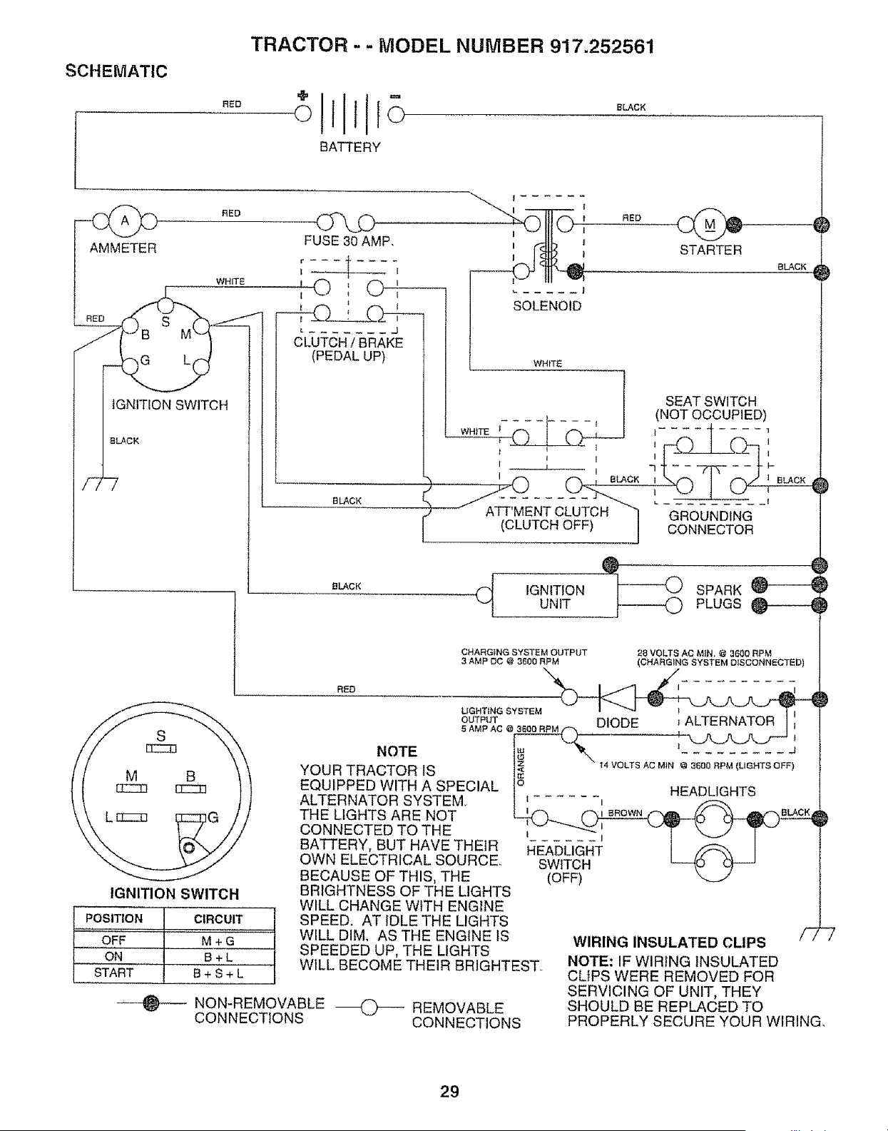
RED
SCHEMATIC
TRACTOR - - MODEL NUMBER 917.252561
÷1 °
oliio
BATTERY
BLACK
AMMETER
G
IGNITION SWITCH
BLACK
RED
WHITE
FUSE 30 AMP.
I { I
I
'O',
1
CLUTCH t BRAKE
(PEDAL UP)
BLACK
1 ......
..... J
SOLENOID
RED
STARTER
BLACK
WHITE
t SEAT SWITCH
_ _ _ (NOT OCCUPIED)
W._TE_ ,-_ I _ : I _.... 4 .... '
':L1---P--k,-_Z-T--" ,_7 I C_-_'
t I I I
, ..... i ('7 ("7_ _ BL_CK _\r'_ " _" ,"-',/ J BLACK
' /-L___L:'_____ i .'_J ! _ ',
/ ^ -l-,r t L ........
3 ATTMENTOLUTC."7 GROUNDING
l (CLUTCH OFF) ] CONNECTOR
8LACK
_C_ IGNITION _)_ SPARK
UNIT PLUGS
CHARGING SYSTEM OUTPUT
3 AMP DC @ 3600 RPM
28 VOLTS AC MIN, @ 3600 RPM
(CHARGING SYSTEM O_SCONNECTED)
IGNITION SWITCH
POSITION
OFF
ON
...........START
CIRCUIT
M+G
B+L
B+S+L
BRIGHTNESS OF THE LIGHTS
WILL CHANGE WtTH ENGINE
SPEED. AT IDLE THE LIGHTS
WILL DIM. AS THE ENGINE tS
SPEEDED UP, THE LIGHTS
WILL. BECOME THEIR BRIGHTEST_
NON-REMOVABLE _ REMOVABLE
CONNECTIONS CONNECTIONS
WIRING INSULATED CLIPS /7
NOTE: IF WIRING INSULATED
CLIPS WERE REMOVED FOR
SERVICING OF UNIT, THEY
SHOULD BE REPLACED TO
PROPERLY SECURE YOUR WIRING.
29
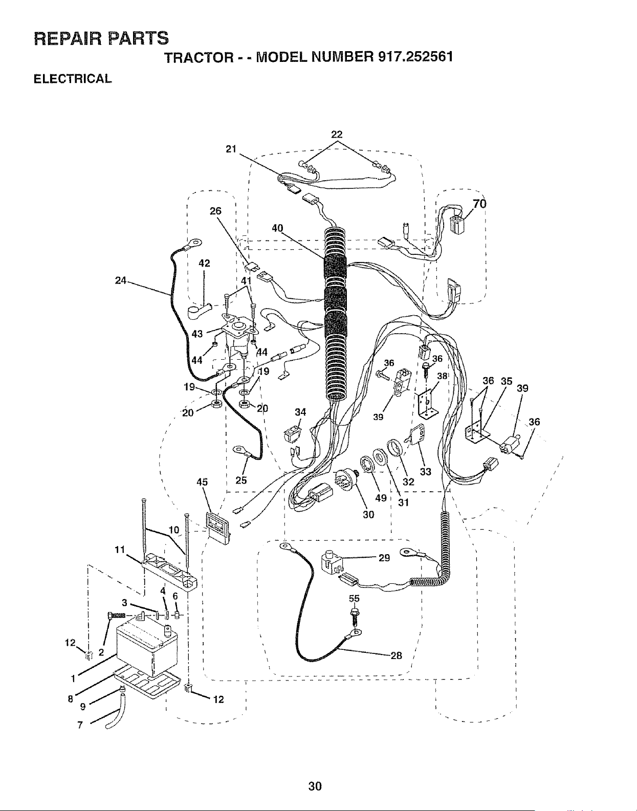
REPADR PARTS
TRACTOR -- MODEL NUMBER 917.252561
ELECTRICAL
11
" i
3
22
42
41
36
36 35
• _20
I I
: I
45 / 25
\
34
39
32
31
30
39
30

REPAIR PARTS
TRACTOR -- MODEL NUMBER 917.252561
ELECTRICAL
KEY PART
NOr NO. DESCRIPTION
1 146140
2 74760412
3 19091016
4 10040400
5 121264X
6 73220400
7 7697J
8 7603J
9 109596X
10 145211
11 145209
I2 145769
19 10090400
20 73350400
21 136850
22 4152J
24 4206J
25 146148
26 108824X
28 145491
29 121305X
30 144921
31 140400
32 141226
33 140403
34 110712X
35 108236X
36 17021008
38 140336
39 109553X
40 146057
41 71110408
42 131563
43 145673
44 73640400
45 121433X
49 11151000
55 17490508
70 140413
Batten!
Bolt, Hex 1/4_20 x 3/4
Washer 9/32 x 5/8 x 16 Gauge
Washer, Lock t/4
Caps, Battery
Nut, Hex 1/4-20
Tube
Tray, Battery
Clamp, Hose
Bolt, Btr Front 1/4-20 x 7-1/2
Holddown Battery Dash Mount
Nut, Push Nylon Battery Front 1/4
Washer, Lock !/4
Nut, Hex, Jam 1/4-20
Harness, Light Socket (With Bulbs)
Light Bulb
Cable, Battery
Cable, Battery
Fuse
Cable, Ground
Switch, Seat
Switch, Ignition 3 Position
Nut, Ignition Switch
Cover, Ignition Switch
Key, Molded, Craftsman
Switch, Light
Bracket, Switch
Screw, Hex, Tapping #10-24 x !/2
Bracket, Switch interlock
Switch, Interlock, Attachment Clutch
Harness, Ignition
Bolt BIk Fin Hex 1/4-20 UNC x 1/2
Cover, Terminal
Solenoid
Nut Keps BIk Hex 1/4-20 UNC
Ammeter Rectangular 6 Amp
Washer Lock Internal Tooth 5/8
Screw Thd rol 5/16-18 x 1/2
Harness, Engine
NOTE: All component dimensions given in U,S. inches
1 inch = 25,4 mm
3'1
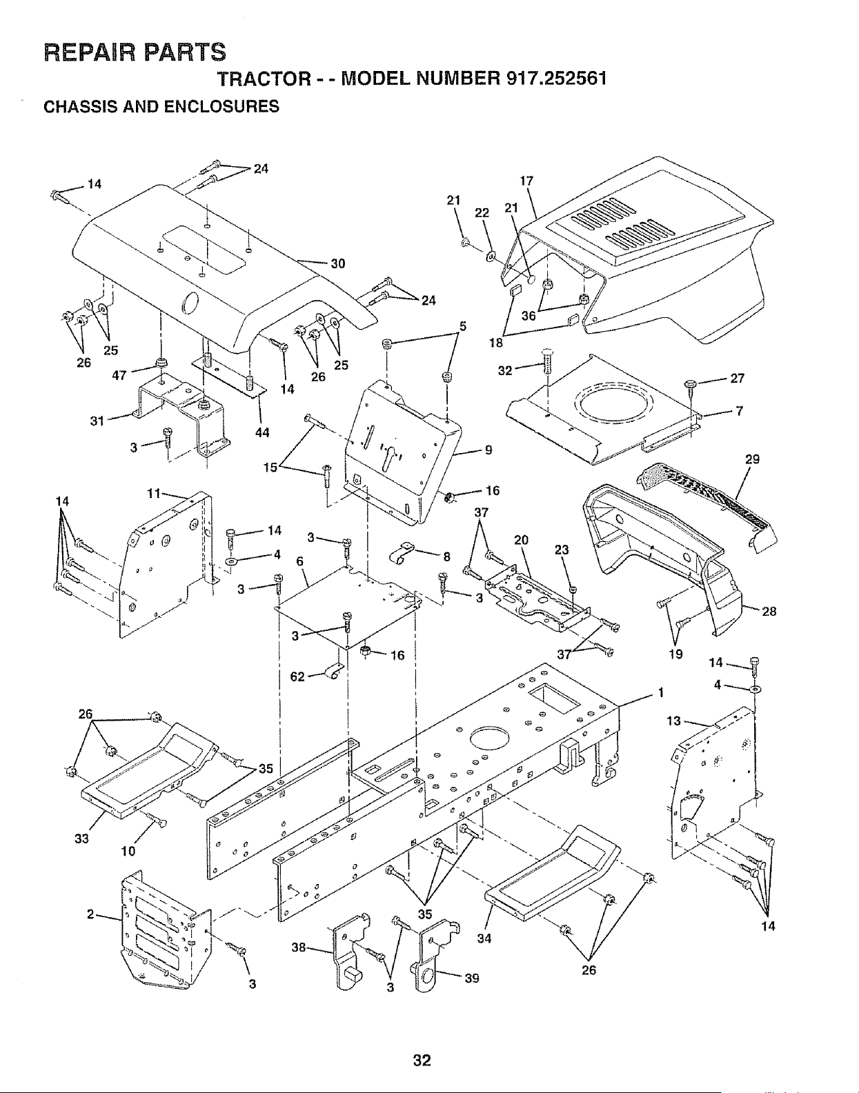
REPARR PARTS
TRACTOR -- MODEL NUMBER 917.252561
CHASSIS AND ENCLOSURES
I
5
26
47
31
14
26
33
10
24
44
4
4
3
30
17
26
25
18
6
29
1
14
26
32
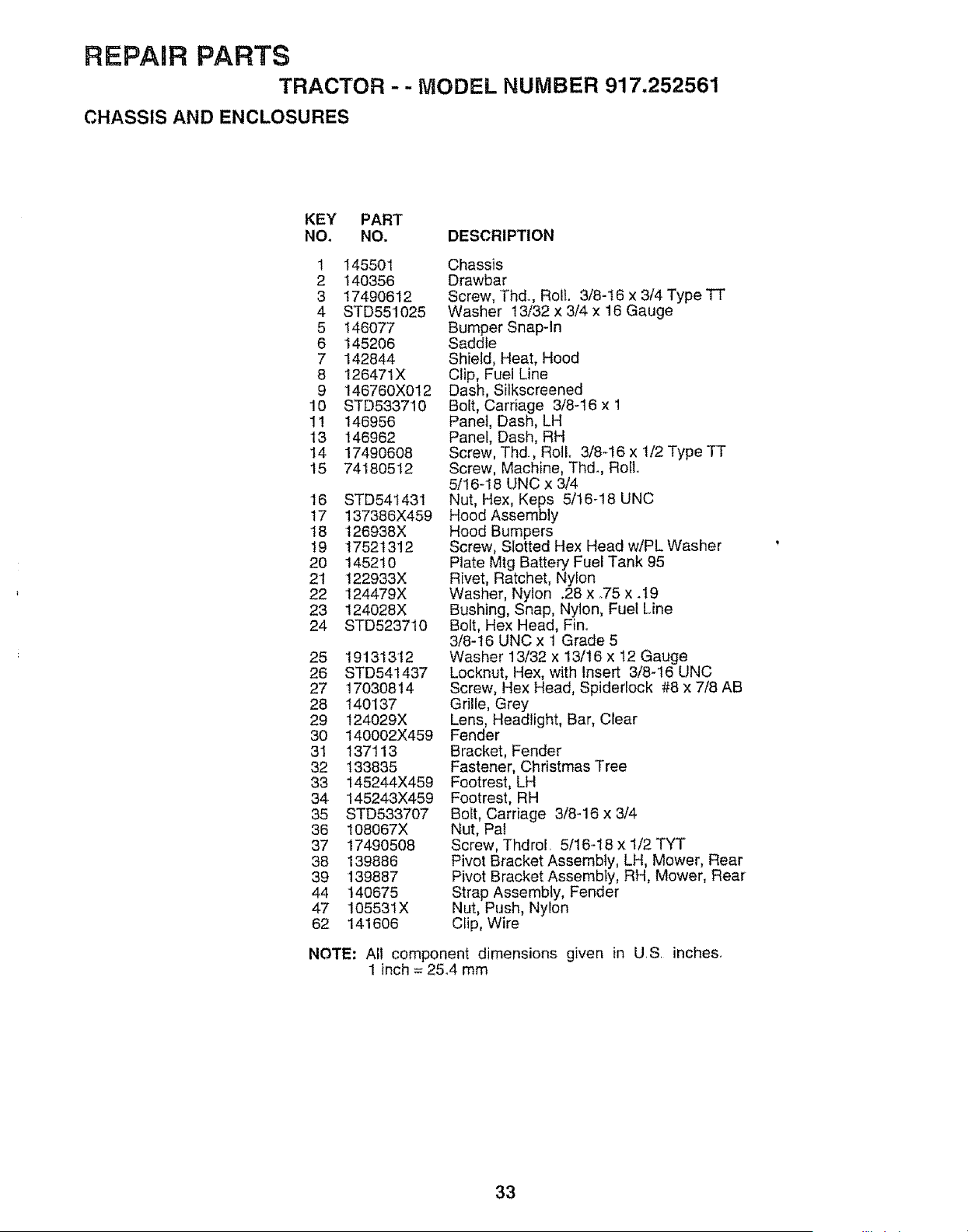
REPAIR PARTS
TRACTOR - - MODEL NUMBER 917,252561
CHASSIS AND ENCLOSURES
KEY PART
NO. NO. DESCRIPTION
1 145501
2 140356
3 1749O612
4 STD551025
5 146077
6 145206
7 142844
8 126471X
9 146760X012
10 STD533710
1! 146956
13 146962
t4 17490608
15 74180512
16 STD541431
17 137386X459
18 t26938X
19 17521312
20 145210
2't 122933X
22 124479X
23 124028X
24 STD523710
25 191313+12
26 STD541437
27 17030814
28 140137
29 124029X
30 t40002X459
3I 137113
32 133835
33 145244X459
34 145243X459
35 STD533707
36 I08067X
37 17490508
38 139886
39 139887
44 140675
47 105531X
62 141606
Chassis
Drawbar
Screw, Thd+, Roll 3/8-t6 x 3/4 Type TT
Washer 13/32 x 3/4 x 18 Gauge
Bumper Snap-In
Saddle
Shield, Heat, Hood
Clip, Fuel Line
Dash, Silkscreened
Bolt, Carriage 3/8-16 x 1
Panel, Dash, LH
Panel, Dash, RH
Screw, Thd, Roll. 3/8-16 x 1/2 Type TT
Screw, Machine, Thd+, RoIL
5/16-18 UNC x 3/4
Nut, Hex, Keps 5/16+18 UNC
Hood Assembly
Hood Bumpers
Screw, Slotted Hex Head w/PL Washer
Plate Mtg Battery Fuel Tank 95
Rivet, Ratchet, Nylon
Washer, Nylon +28x +75x .I9
Bushing, Snap, Nylon, Fuel Line
Bolt, Hex Head, Fin°
3/8-16 UNC x 1 Grade 5
Washer 13/32 x 13/16 x 12 Gauge
Locknut, Hex, with Insert 3/8+16 UNC
Screw, Hex Head, Spidertock #8 x 7/8 AB
Grille, Grey
Lens, Headlight, Bar, Ctear
Fender
Bracket, Fender
Fastener, Christmas Tree
Footrest, LH
Footrest, RH
Bolt, Carriage 3/8-16 x 3/4
Nut, Pal
Screw, ThdroE+ 5/16+18 x 1/2 TYT
Pivot Bracket Assembly, LH, Mower, Rear
Pivot Bracket Assembly, RH, Mower, Rear
Strap Assembly, Fender
Nut, Push, Nylon
Ciip, Wire
NOTE: All component dimensions given in U,S, inches+
1 inch = 25,4 mm
33
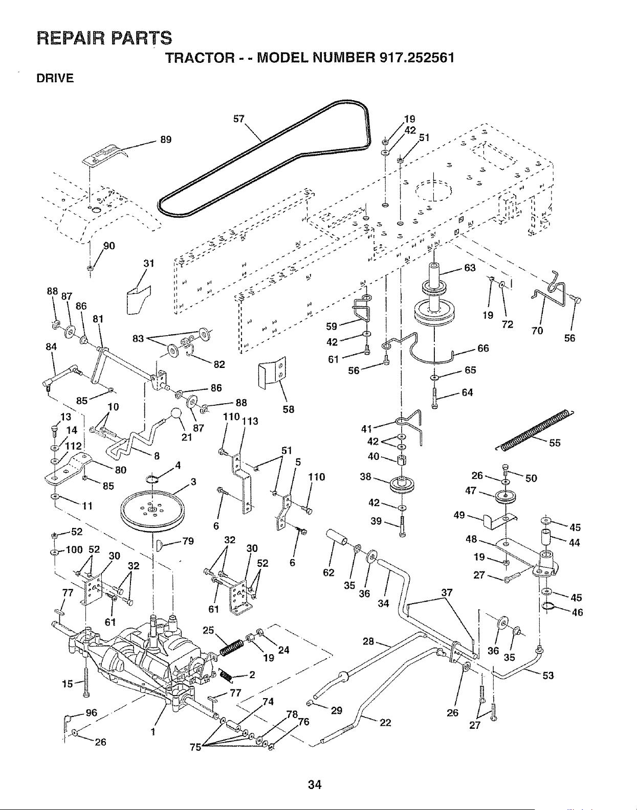
REPAIR PARTS
TRACTOR - - MODEL NUMBER 917.252561
DRIVE
88 87
84
13
86
81
51
5
6
32
// 30 2
42 >_
61 _
5611 •
64
tlO
62
35
36
34
56
22
26
27
34
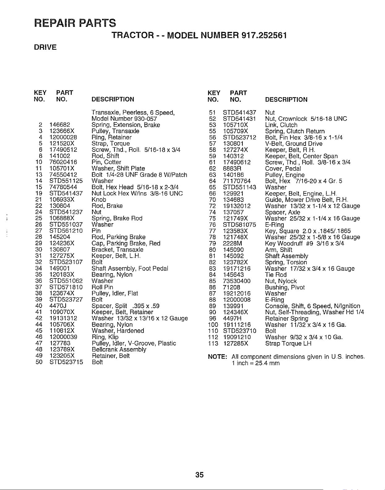
REPARR PARTS
TRACTOR -- MODEL NUMBER 917.252561
DRIVE
KEY PART KEY PART
NO, NO. DESCRIPTION NO. NO, DESCRIPTION
Transaxle, Peerless, 6 Speed, 51 STD541437
Model Number930-057 52 STD541431
2 146682 Spring, Extension, Brake 53 105710X
3 123666X Pulley, Transaxle 55 105709X
4 12000028 Ring, Retainer 56 STD523712
5 121520X Strap, Torque 57 130801
6 17490512 Screw, Thd+, Roll 5/16-18 x 3/4 58 127274X
8 141002 Rod, Shift 59 140312
10 76020416 Pin, Cotter 61 17490612
11 105701X Washer, Shift Plate 62 8883R
13 74550412 Bolt '1/4-28 UNF Grade 8 W/Patch 63 140186
14 STD551125 Washer 64 71170764
15 74780544 Bolt, Hex Head 5/16-18 x 2-3/4 65 STD55t143
19 STD541437 Nut Lock HexW/lns 3/8-16 UNC 66 129921
21 106933X Knob 70 134683
22 130804 Rod, Brake 72 19132012
24 STD541237 Nut 74 137057
25 106888X Spring, Brake Rod 75 t21749X
26 STD551037 Washer 76 STD581075
27 STD561210 Pin 77 I23583X
28 145204 Rod, Parking Brake 78 t21748X
29 124236X Cap, Parking Brake, Red 79 2228M
30 130807 Bracket, Transaxle 80 145090
31 127275X Keeper, Belt, L.H_ 81 145092
32 STD523107 Bolt 82 123782X
34 149001 Shaft AssembIy, Foot Pedal 83 19171216
35 120183X Bearing, Nylon 84 145643
36 STD551062 Washer 85 73530400
37 STD571810 Roll Pin 86 71208
38 123674X Pulley, idler, Flat 87 19212016
39 STD523727 Bolt 88 12000008
40 4470J Spacer, Split .395 x.59 89 139991
41 109070X Keeper, Belt, Retainer 90 124346X
42 19131312 Washer 13/32 x 13/16 x 12 Gauge 96 4497H
44 105706X Bearing, Nylon 100 19111216
45 110812X Washer, Hardened 110 STD523710
46 12000039 Ring, Klip 112 19091210
47 127783 Pulley, Idler, V-Groove, Plastic 113 127285X
48 123789X Bellcrank Assembly
49 123205X Retainer, Belt
50 STD523715 Bolt
Nut
Nut, Crownlock 5/16-18 UNC
Link, Clutch
Spring, Clutch Return
Bolt, Fin Hex 3/8-16 x 1-1/4
V-Belt, Ground Drive
Keeper, Belt, R.H_
Keeper, Belt, Center Span
Screw, Thd, ROilr. 3/8-16 X 3/4
Cover, Pedal
Pulley, Engine
Bolt, Hex 7/16-20 x 4 Gr. 5
Washer
Keeper, Belt, Engine, L.H+
Guide, Mower Drive Belt, R.H
Washer 13/32 x 1-1/4 x 12 Gauge
Spacer, Axle
Washer 25/32 x 1-1/4 x 16 Gauge
E-Ring
Key, Square 2+0 x .1845/+1865
Washer 25/32 x 1-5/8 x 16 Gauge
Key Woodruff #9 3/16 x 3/4
Arm, Shift
Shaft Assembly
Spring, Torsion
Washer 17/32 x 3/4 x 16 Gauge
Tie Rod
Nut, Nylock
Bushing, Pivot
Washer
E-Ring
Console, Shift, 6 Speed, N/Ignition
Nut, Self-Threading, Washer Hd 1/4
Retainer Spring
Washer 11/32 x 3/4x 16 Ga..
Bolt
Washer 9/32 x 3/4 × 10 Ga_
Strap Torque LH
NOTE: All component dimensions given in U.S. inches.
1 inch = 25.4 mm
35
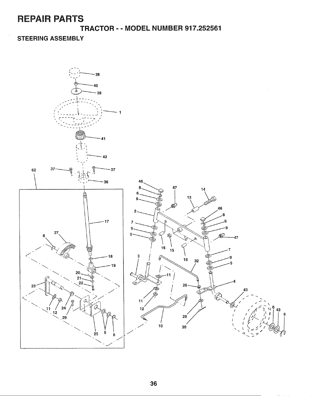
REPAIR PARTS
TRACTOR -- MODEL NUMBER 917.252561
STEERING ASSEMBLY
41
l i
t
27
47
43
36
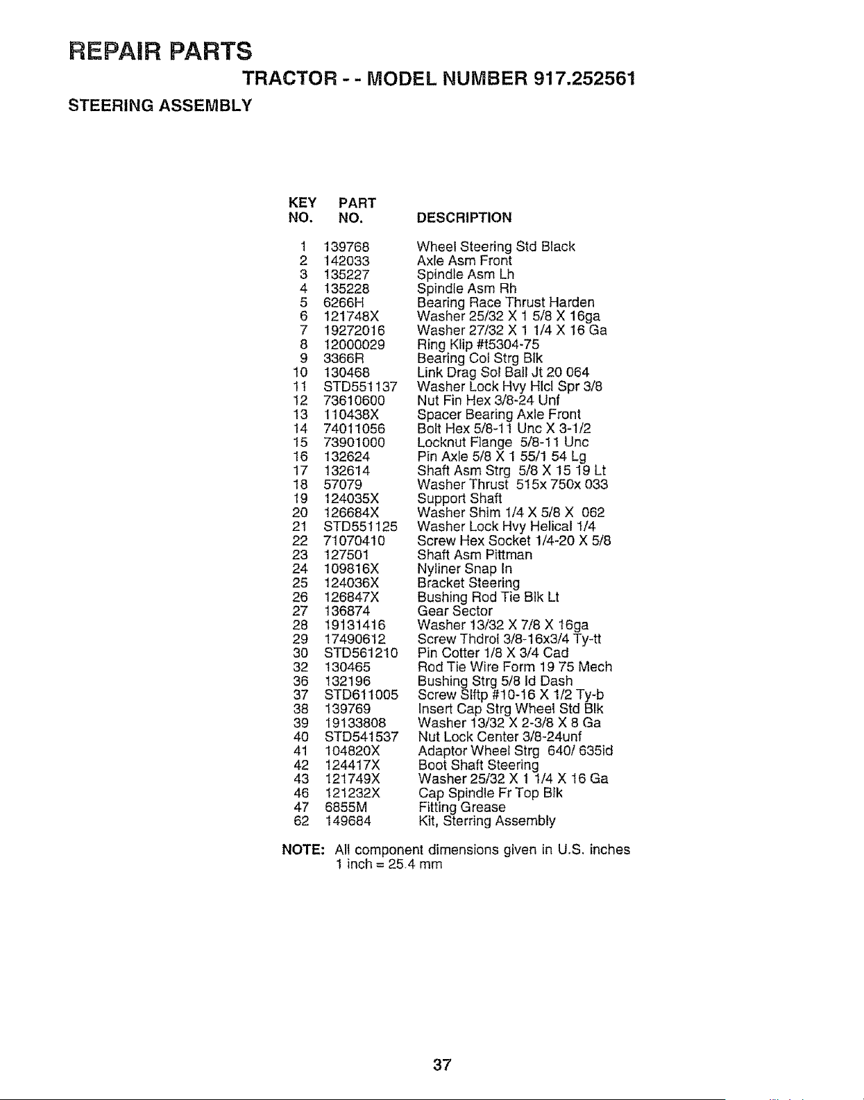
REPAIR PARTS
TRACTOR -- MODEL NUMBER 917.252561
STEERING ASSEMBLY
KEY PART
NO. NO. DESCRIPTION
1 139768
2 142033
3 135227
4 135228
5 6266H
6 121748X
7 19272016
8 12000029
9 3366R
10 130468
11 STD551137
12 73610600
13 110438X
14 74011056
15 73901000
16 132624
17 132614
18 57079
19 124035X
20 126684X
21 STD551125
22 71070410
23 127501
24 109816X
25 124036X
26 126847X
27 136874
28 19131416
29 17490612
30 STD561210
32 130465
36 132196
37 STD61!005
38 139769
39 19133808
40 STD541537
41 104820X
42 124417X
43 I21749X
46 121232X
47 6855M
62 149684
Wheel Steering Std Black
Axle Asm Front
Spindle Asm Lh
Spindle Asm Rh
Bearing Race Thrust Harden
Washer 25/32 X 1 5/8 X 16ga
Washer 27/32 X 1 1/4 X 16 Ga
Ring Klip #t5304-75
Bearing Cot Strg B1k
Link Drag Sol Ball Jt 20 064
Washer Lock Hvy HIcl Spr 3/8
Nut Fin Hex 3/8-24 Unf
Spacer Bearing Axle Front
Bolt Hex 5/8-11 Unc X 3-1/2
Locknut Flange 5/8-11 Unc
Pin Axle 5/8 X 1 55/1 54 Lg
Shaft Asm Strg 5/8 X !5 19 Lt
Washer Thrust 515x 750x 033
Support Shaft
Washer Shim 1/4 X 5/8 X 062
Washer Lock Hvy Helical 1/4
Screw Hex Socket 1/4-20 X 5/8
Shaft Asm Pittman
Nyliner Snap in
Bracket Steering
Bushing Rod Tie Blk Lt
Gear Sector
Washer 13/32 X 7/8 X t6ga
Screw Thdrol 3/8-16x3/4 Ty-tt
Pin Cotter 1/8 X 3/4 Cad
Rod Tie Wire Form 19 75 Mech
Bushing Strg 5/8 ld Dash
Screw SIftp #10-16 X 1/2 Ty-b
Insert Cap Strg Wheel Std BIk
Washer 13/32 X 2-3/8 X 8 Ga
Nut Lock Center 3/8-24unf
Adaptor Wheel Strg 640/635id
Boot Shaft Steering
Washer 25/32 X 1 t/4 X 16 Ga
Cap Spindle Fr Top Bfk
Fitting Grease
Kit, Sterring Assembly
NOTE: All component dimensions given in U.S. inches
1 inch = 25.4 mm
37
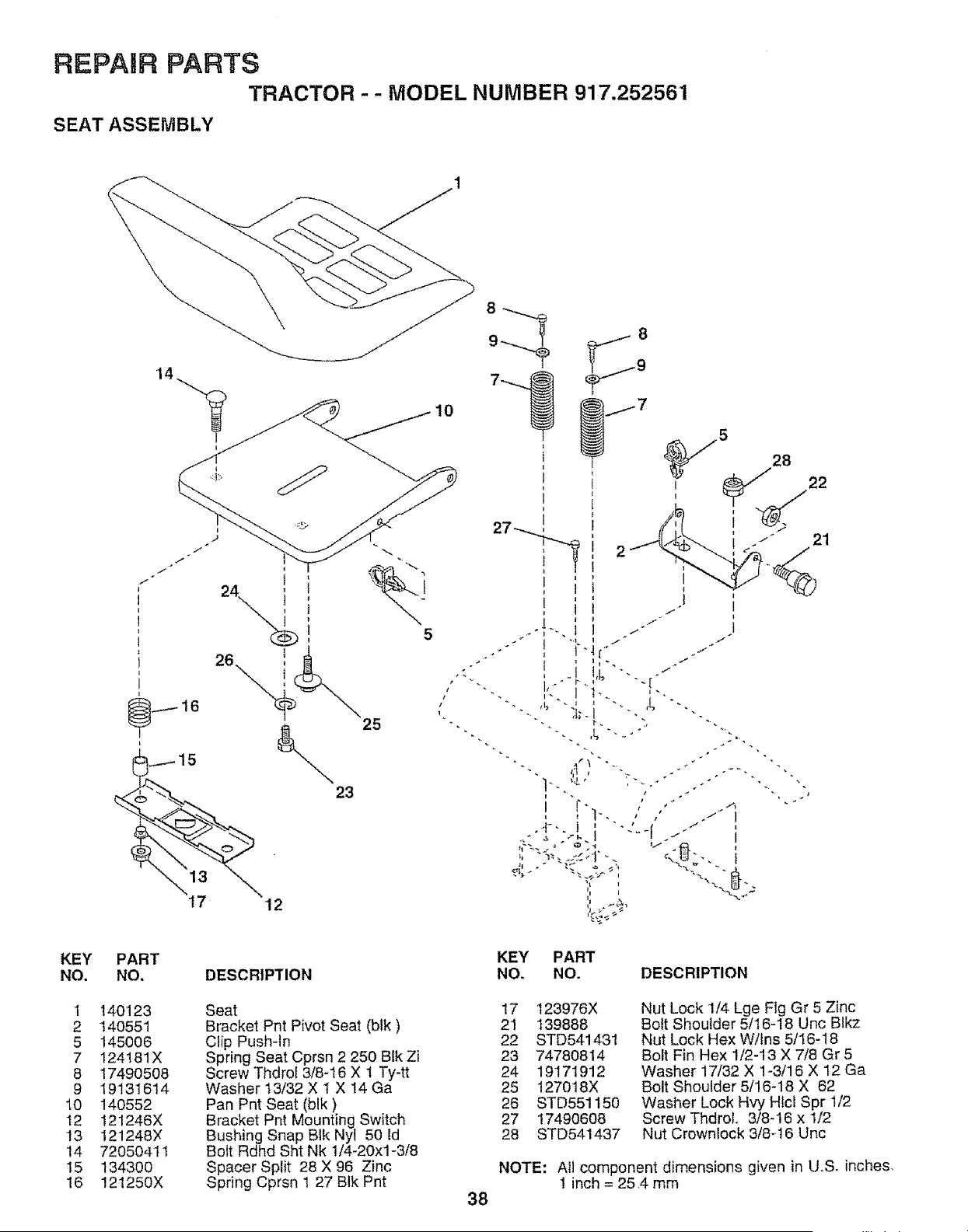
REPAIR PARTS
TRACTOR -- MODEL NUMBER 917.252561
SEAT ASSEMBLY
i
KEY PART
NO. NO,
1 140123
2 140551
5 145006
7 124181X
8 17490508
9 19131614
10 140552
12 121246X
13 121248X
14 72050411
15 134300
16 121250X
5
25
23
DESCRIPTION
Seat
Bracket Pnt Pivot Seat (blk)
Clip Push-In
Spring Seat Cprsn 2 250 BIk Zi
Screw Thdrot 3/8-16 X 1 Ty-tt
Washer 13/32 X 1 X 14 Ga
Pan Pnt Seat (blk)
Bracket Pnt Mounting Switch
Bushing Snap BIk Nyl 50 Id
Bolt Rdhd Sht Nk 1/4-20xl-3/8
Spacer Split 28 X 96 Zinc
Spring Cprsn 1 27 BIk Pnt
28
KEY PART
NO_ NO. DESCRIPTION
38
17 123976X
21 139888
22 STD541431
23 74780814
24 19171912
25 127018X
26 STD551150
27 17490608
28 STD541437
Nut Lock 1/4 Lge Fig Gr 5 Zinc
Bolt Shoulder 5/16-18 Unc Blkz
Nut Lock Hex W!Ins 5/16-18
Bolt Fin Hex 1/2-13 X 7/8 Gr 5
Washer 17/32 X 1-3/16 X 12 Ga
Bolt Shoulder 5/!6-18 X 62
Washer Lock Hvy HIcl Spr 1/2
Screw ThdroL 3/8-16 x 1/2
Nut Crownlock 3/8-16 Uric
NOTE: All component dimensions given in LJ.S. inches,
1 inch = 25,4 mm
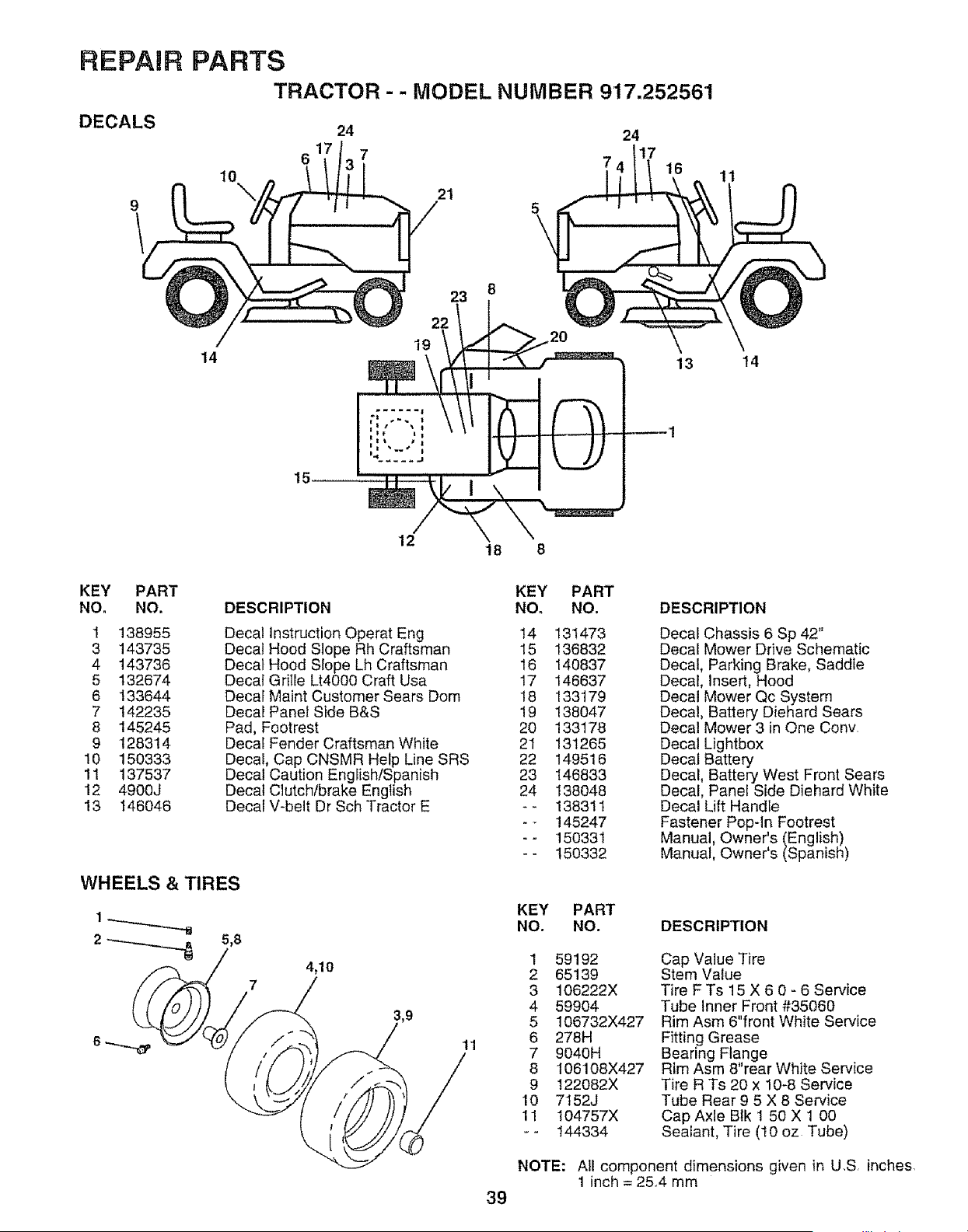
REPAIR PARTS
TRACTOR - - MODEL NUMBER 9'17.252561
DECALS
24 24
6 7 7
16
11
14
23
22
t9
13 t4
15
12
18 8
KEY PART
NO. NO.
1 138955
3 143735
4 143736
5 132674
6 133644
7 142235
8 145245
9 128314
10 150333
11 137537
12 4900J
13 146046
DESCRIPTION
Decal Instruction Operat Eng
Decal Hood Slope Rh Craftsman
Decal Hood Slope Lh Craftsman
Decal Grille Lt4000 Craft Usa
Decal Maint Customer Sears Dora
Decal Panel Side B&S
Pad, Footrest
Decal Fender Craftsman White
Decal, Cap CNSMR Help Line SRS
Decal Caution English/Spanish
Decal Clutch/brake English
Decal V-belt Dr Sch Tractor E
WHEELS & TIRES
5,8
4,10
KEY PART
NO. NO.
14 131473
15 136832
16 140837
17 146637
18 133179
19 138047
20 133178
21 131265
22 149516
23 146833
24 138048
-- 138311
-- 145247
-- 150331
-- 150332
DESCRIPTION
Decal Chassis 6 Sp 42"
Decal Mower Drive Schematic
Decal, Parking Brake, Saddle
Decal, Insert, Hood
Decal Mower Qc System
Decal, Battery Diehard Sears
Decal Mower 3 in One Conv,
Decal Lightbox
Decal Battery
Decal, Battery West Front Sears
Decal, Panel Side Diehard White
Decal Lift Handle
Fastener Pop-In Footrest
Manual, Owner's (English)
Manual, Owner's (Spanish)
11
KEY PART
NO. NO. DESCRIPTION
1 59192
2 65139
3 106222X
4 59904
5 106732X427
6 278H
7 9040H
8 106108X427
9 122082X
10 7152J
11 104757X
-- 144334
Cap Value Tire
Stem Value
Tire F Ts 15 X 6 0 - 6 Service
Tube inner Front #35060
Rim Asm 6"front White Service
Fitting Grease
Bearing Flange
Rim Asm 8"rear White Service
Tire R Ts 20 x 10-8 Service
Tube Rear 9 5 X 8 Service
Cap Axle Blk 1 50 X 1 00
Sealant, Tire (10 oz Tube)
NOTE: All component dimensions given in U,S, inches.
1 inch = 25.4 mm
39
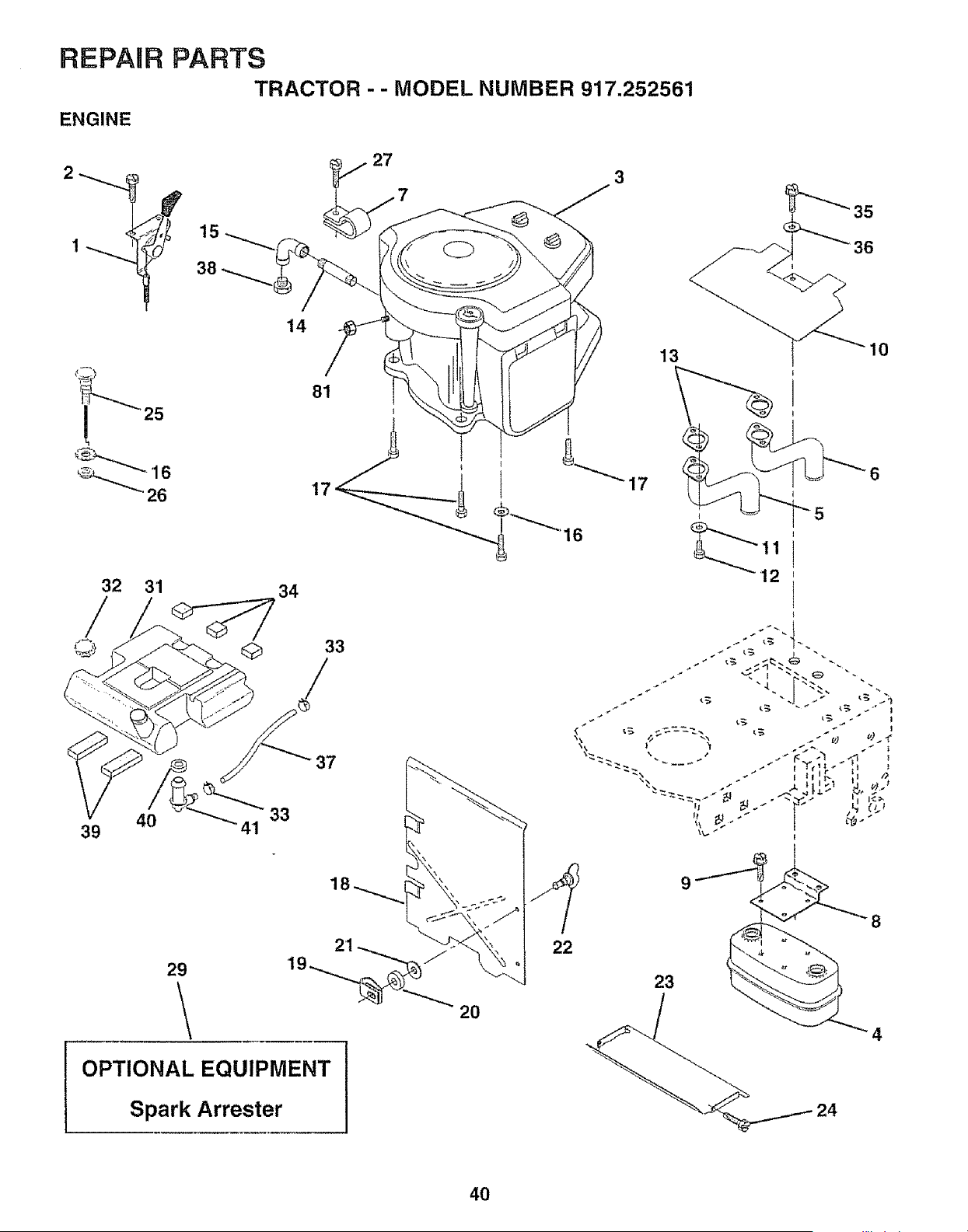
REPAUR PARTS
TRACTOR - - MODEL NUMBER 917.252561
ENGINE
15
27
7
35
36
32 31
© Q
39 4O 41
14
13
10
©
34
33
/
37
33
29
\
21
OPTIONAL EQUIPMENT
Spark Arrester
2O
22
23
4O
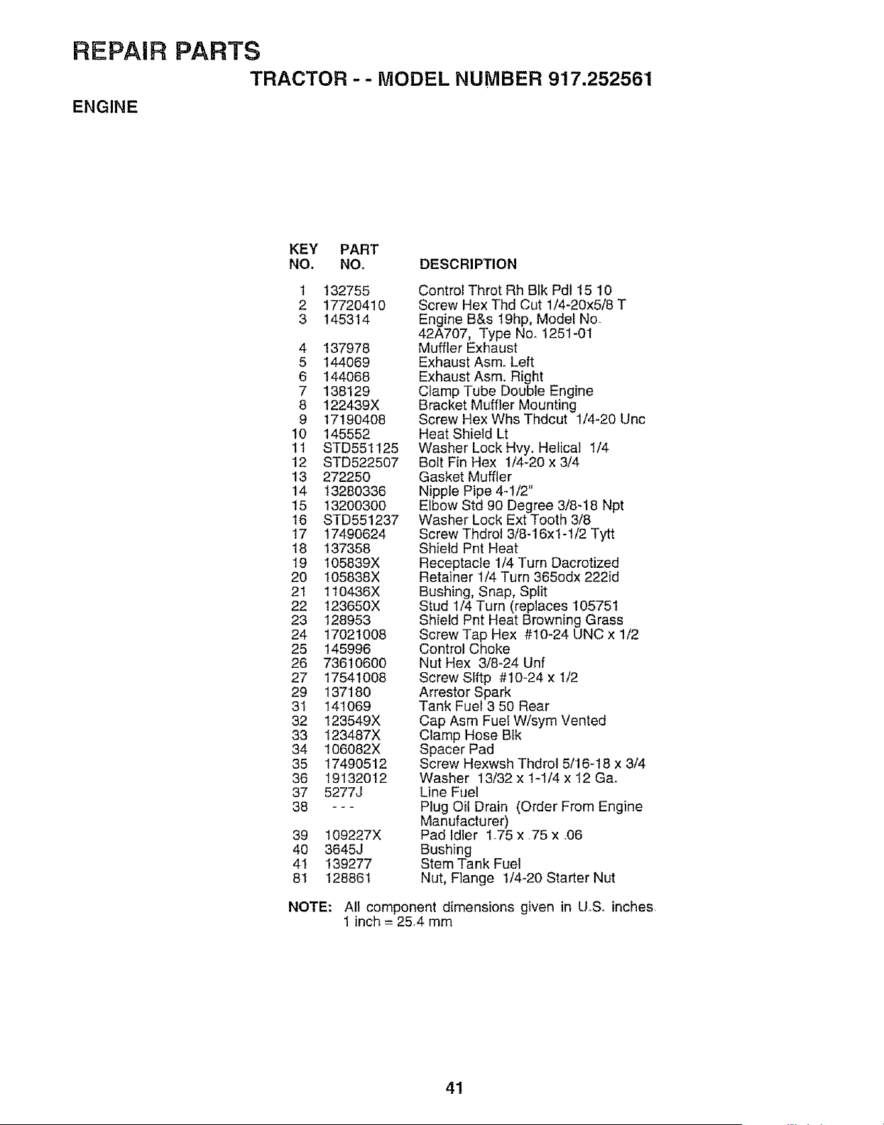
REPAIR PARTS
TRACTOR -- MODEL NUMBER 917.252561
ENGINE
KEY PART
NO. NO. DESCRIPTION
I
2
3
132755
17720410
145314
4 137978
5 144069
6 144O68
7 138129
8 122439X
9 17190408
10 145552
11 STD551125
12 STD522507
13 272250
14 13280336
15 13200300
16 STD551237
17 17490624
18 137358
19 105839X
20 t05838X
21 1t0436X
22 123650X
23 128953
24 17021008
25 145996
26 73610600
27 17541008
29 137180
3I 141069
32 123549X
33 123487X
34 106082X
35 17490512
36 19132012
37 5277J
38 ---
39 109227X
40 3645J
41 139277
81 128861
Control Throt Rh Blk Pd115 10
Screw Hex Thd Cut 1/4-20x5/8 T
Engine B&s 19hp, Model No.
42A707, Type No, 1251-01
Muffler Exhaust
Exhaust Asm. Left
Exhaust Asm. Right
Clamp Tube Double Engine
Bracket Muffler Mounting
Screw Hex Whs Thdcut 1/4-20 Unc
Heat Shield Lt
Washer Lock Hvy, Helical 1/4
Bolt Fin Hex 1/4-20 x 3/4
Gasket Muffler
Nipple Pipe 4-!/2"
Elbow Std 90 Degree 3/8-18 Npt
Washer Lock Ext Tooth 3/8
Screw Thdrol 3/8-16x1-1/2 Tytt
Shield Pnt Heat
Receptacle 1/4 Turn Dacrotized
Retainer t/4 Turn 365odx 222id
Bushing, Snap, Split
Stud 1/4 Turn (replaces 105751
Shield Pnt Heat Browning Grass
Screw Tap Hex #10-24 UNC x 1/2
Control Choke
Nut Hex 3/8-24 Unf
Screw Slftp #10-24 x I/2
Arrestor Spark
Tank Fuel 3 50 Rear
Cap Asm Fuel W/sym Vented
Clamp Hose Btk
Spacer Pad
Screw Hexwsh Thdrot 5116-18 x 3/4
Washer 13/32 x 1-1/4 x 12 Gao
Line Fuel
Plug Oil Drain (Order From Engine
Manufacturer)
Pad Idler 1.75 x .75 x .06
Bushing
Stem Tank Fuel
Nut, Flange 1/4-20 Starter Nut
NOTE: All component dimensions given in U.S. inches,
1 inch = 25,4 mm
41
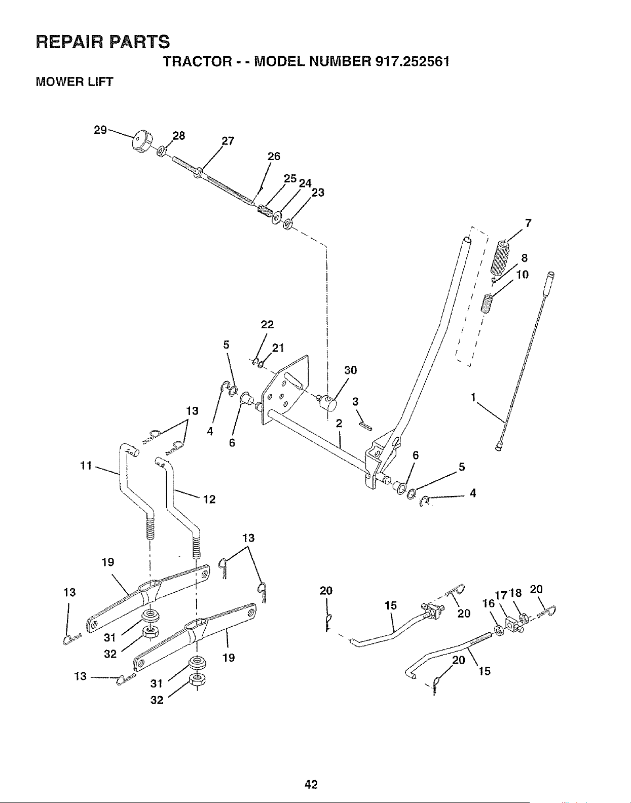
REPAIR PARTS
TRACTOR - - MODEL NUMBER 917.252561
MOWER LIFT
1'1
19
'13
28 27
/ 26
'13
4
6
12
22
21
13
31 _ 19
32
2O
6
15
7
!
II 1"
l
t
1 I
42
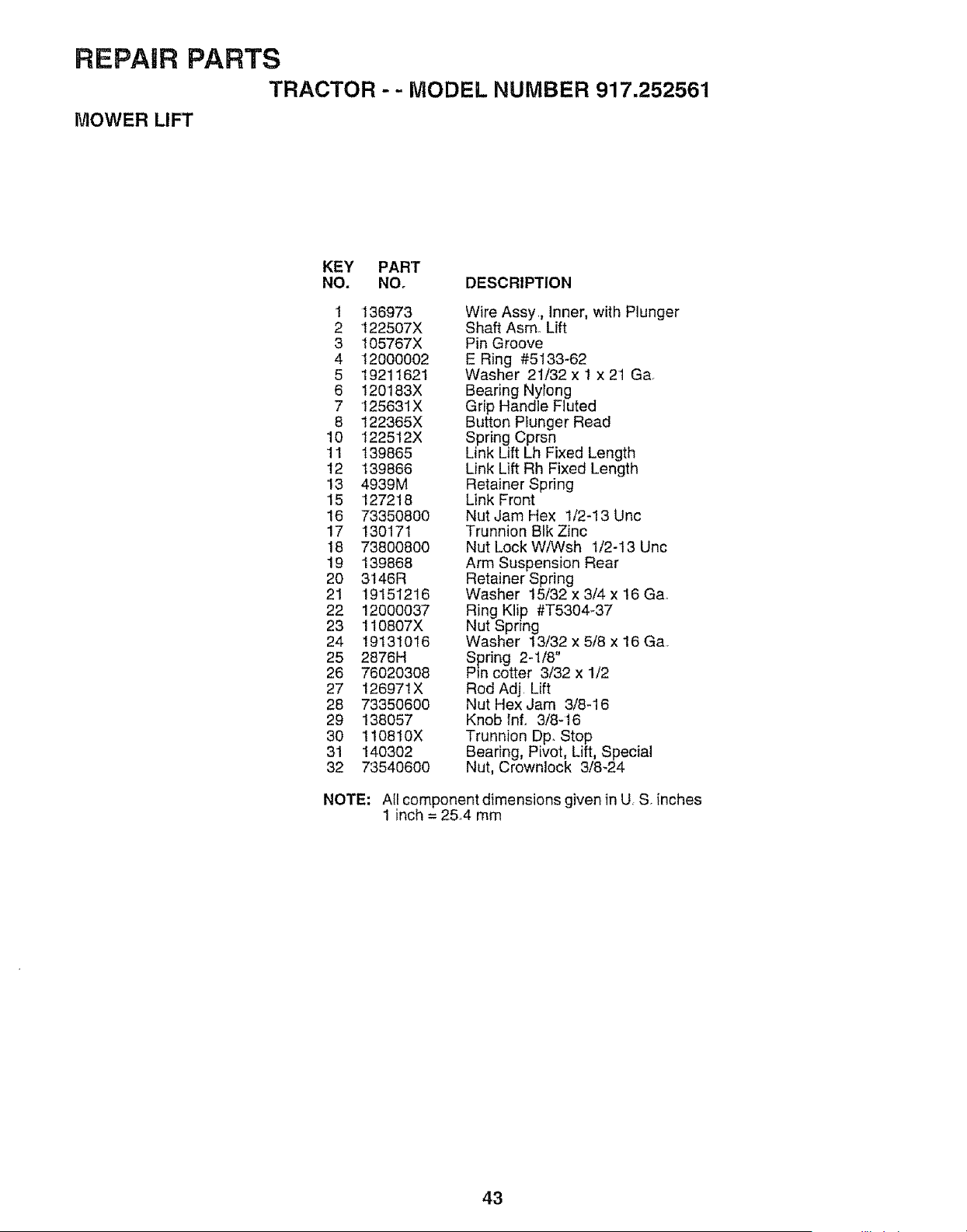
REPAIR PARTS
TRACTOR -- MODEL NUMBER 917.252561
MOWER LIFT
KEY PART
NO. NO. DESCRIPTION
1 136973
2 122507X
3 105767X
4 12000002
5 19211621
6 120183X
7 125631X
8 t22365X
10 122512X
11 139865
t2 139866
13 4939M
15 127218
16 73350800
17 130171
18 73800800
19 139868
20 3t46R
21 19151216
22 12000037
23 110807X
24 19131016
25 2876H
26 76020308
27 126971X
28 73350600
29 138057
30 110810X
31 140302
32 73540600
Wire Assy,, lnner, with Plunger
Shaft Asmo Lift
Pin Groove
E Ring #5133-62
Washer 21/32 x 1 x 21 Ga,
Bearing Nytong
Grip Handle Fluted
Button Ptunger Read
Spring Cprsn
Link Lift Lh Fixed Length
Link Lift Rh Fixed Length
Retainer Spring
Link Front
Nut Jam Hex 1/2-13 Unc
Trunnion BIk Zinc
Nut Lock W/Wsh 1/2-13 Unc
Arm Suspension Rear
Retainer Spring
Washer 15/32 x 3/4 x 16 Gao
Ring Klip #T5304-37
Nut Spring
Washer 13/32 x 5/8 x t6 Ga,
Spring 2q/8"
Pin cotter 3/32 x 1/2
Rod Adj, Lift
Nut Hex Jam 3/8-16
Knob lnf,, 3/8q6
Trunnion Dp, Stop
Bearing, Pivot, Lift, Special
Nut, Crownlock 3/8-24
NOTE: Ail component dimensions given in U S. inches
1 inch = 2&4 mm
43
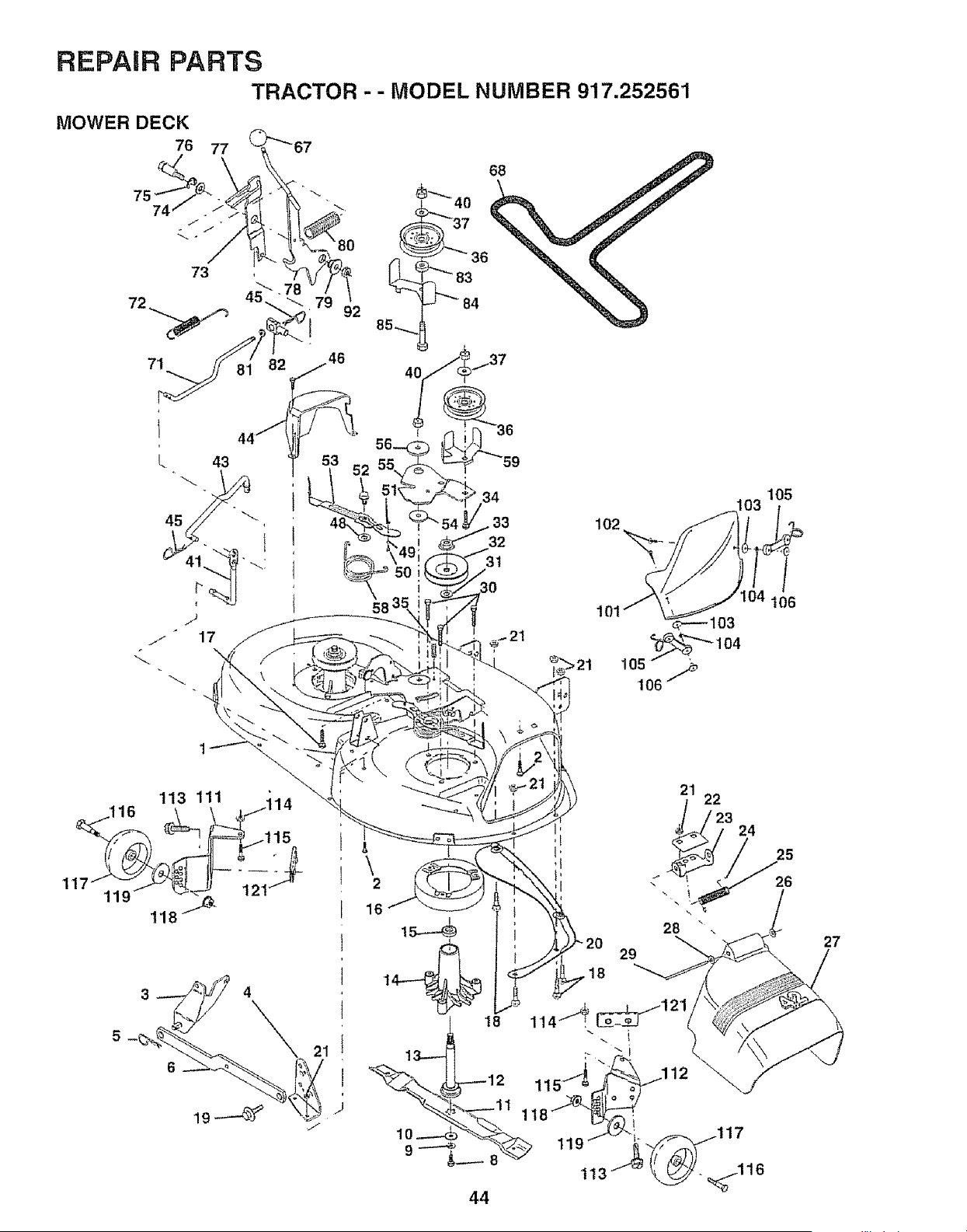
\
\
\\
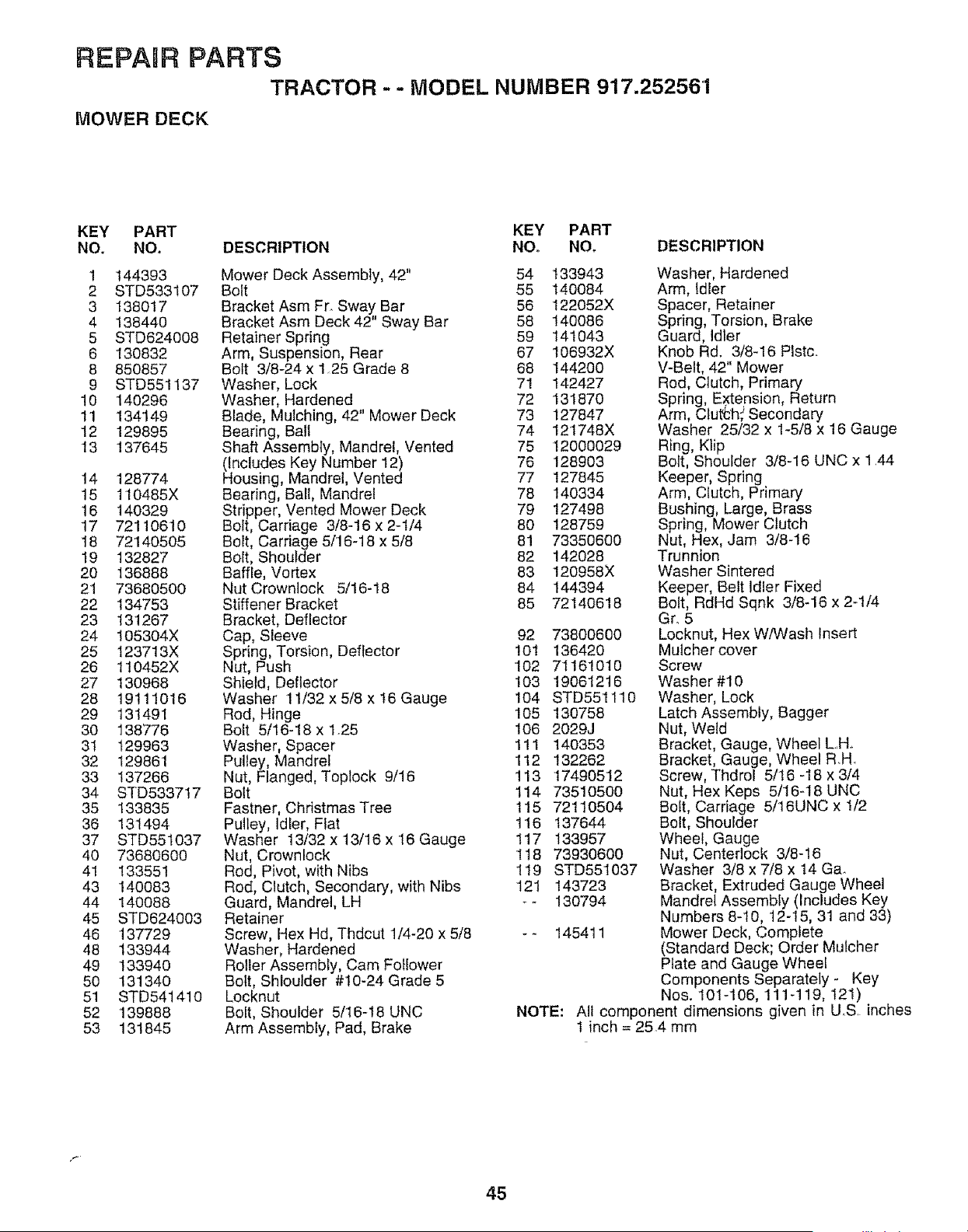
REPAIR PARTS
TRACTOR -- MODEL NUMBER 917.25256'1
MOWER DECK
KEY PART KEY PART
NO. NO. DESCRIPTION NO. NO. DESCRIPTION
1 144393
2 STD533107
3 138017
4 138440
5 STD624008
6 130832
8 850857
9 STD551137
10 140296
11 134'149
12 129895
13 137645
14 128774
15 110485X
16 140329
17 72110610
I8 72140505
19 132827
20 136888
21 73680500
22 134753
23 13'1267
24 105304X
25 123713X
26 110452X
27 130968
28 19111016
29 131491
30 138776
31 129963
32 129861
33 137266
34 STD5337t7
35 133835
36 131494
37 STD551037
40 73680600
41 133551
43 140083
44 140088
45 STD624003
46 137729
48 133944
49 133940
50 131340
51 STD541410
52 139888
53 131845
Mower Deck Assembly, 42" 54
Bolt 55
Bracket Asm Fr. Sway Bar 56
Bracket Asm Deck 42" Sway Bar 58
Retainer Spring 59
Arm, Suspension, Rear 67
Bolt 3/8-24 x 1.25 Grade 8 68
Washer, Lock 71
Washer, Hardened 72
Blade, Mulching, 42" Mower Deck 73
Bearing, Ball 74
Shaft Assembly, Mandrel, Vented 75
(Includes Key Number 12) 76
Housing, Mandrel, Vented 77
Bearing, Ball, Mandrel 78
Stripper, Vented Mower Deck 79
Bolt, Carriage 3/8-16 x 2-1/4 80
Bolt, Carriage 5/'16-18 x 5/8 8!
Bolt, Shoulder 82
Baffle, Vortex 83
Nut Crownlock 5/16-18 84
Stiffener Bracket 85
Bracket, Deflector
Cap, Sleeve 92
Spring, Torsion, Deflector 10I
Nut, Push 102
Shield, Deflector 103
Washer 11/32 x 5/8 x I6 Gauge 104
Rod, Hinge 105
Bolt 5/i6-18 x 1.25 106
Washer, Spacer 111
Pulley, Mandrel 112
Nut, Flanged, Toplock 9/16 !13
Bolt 114
Fastner, Christmas Tree 115
Pulley, Idler, Fiat 116
Washer 13/32 x 13/16x 16 Gauge 117
Nut, Crownlock 118
Rod, Pivot, with Nibs '119
Rod, Clutch, Secondary, with Nibs 121
Guard, Mandrel, LH _-
Retainer
Screw, Hex Hd, Thdcut 1/4-20 x 5/8 - -
Washer, Hardened
Roller Assembly, Cam Follower
Bolt, SHoulder #10-24 Grade 5
Locknut
Bolt, Shoulder 5/16-18 UNC NOTE:
Arm Assembly, Pad, Brake
133943
140084
122052X
140086
141043
106932X
144200
142427
131870
127847
121748X
12000029
128903
127845
140334
127498
128759
73350600
142028
120958X
144394
72140618
73800600
136420
71161O1O
19061216
STD551110
130758
2029J
140353
132262
17490512
73510500
72110504
137644
133957
73930600
STD551037
143723
130794
145411
Washer, Hardened
Arm, Idler
Spacer, Retainer
Spring, Torsion, Brake
Guard, Idler
Knob Rd. 3/8-16 Plstc.
V-Belt, 42" Mower
Rod, Clutch, Primary
Spring, Extension, Return
Arm, ClutCh,_Secondary
Washer 25/32 x 1_5/8 x 16 Gauge
Ring, Klip
Bolt, Shoulder 3/8-16 UNC x 1 44
Keeper, Spring
Arm, Clutch, Primary
Bushing, Large, Brass
Spring, Mower Clutch
Nut, Hex, Jam 3/8-16
Trunnion
Washer Sintered
Keeper, Belt Idler Fixed
Bolt, RdHd Sqnk 3/8-16 x 2-1/4
Gr. 5
Locknut, Hex W/Wash Insert
Mulcher cover
Screw
Washer #10
Washer, Lock
Latch Assembly, Bagger
Nut, Weld
Bracket, Gauge, Wheel L.H.
Bracket, Gauge, Wheel RH
Screw, Thdrol 5/16 -18 x 3/4
Nut, Hex Keps 5/16-t8 UNC
Bolt, Carriage 5/16UNC x 1/2
Bolt, Shoulder
Wheel, Gauge
Nut, Centerlock 3/8-16
Washer 3/8 x 7/8 x 14 Ga.
Bracket, Extruded Gauge Wheel
Mandrel Assembly (Includes Key
Numbers 8-I0, 12-15, 31 and 33)
Mower Deck, Complete
(Standard Deck; Order Mulcher
Plate and Gauge Wheel
Components Separately- Key
Nos. 101-106, 111-119, t21)
A!l component dimensions given in US inches
1 inch = 25.4 mm
45
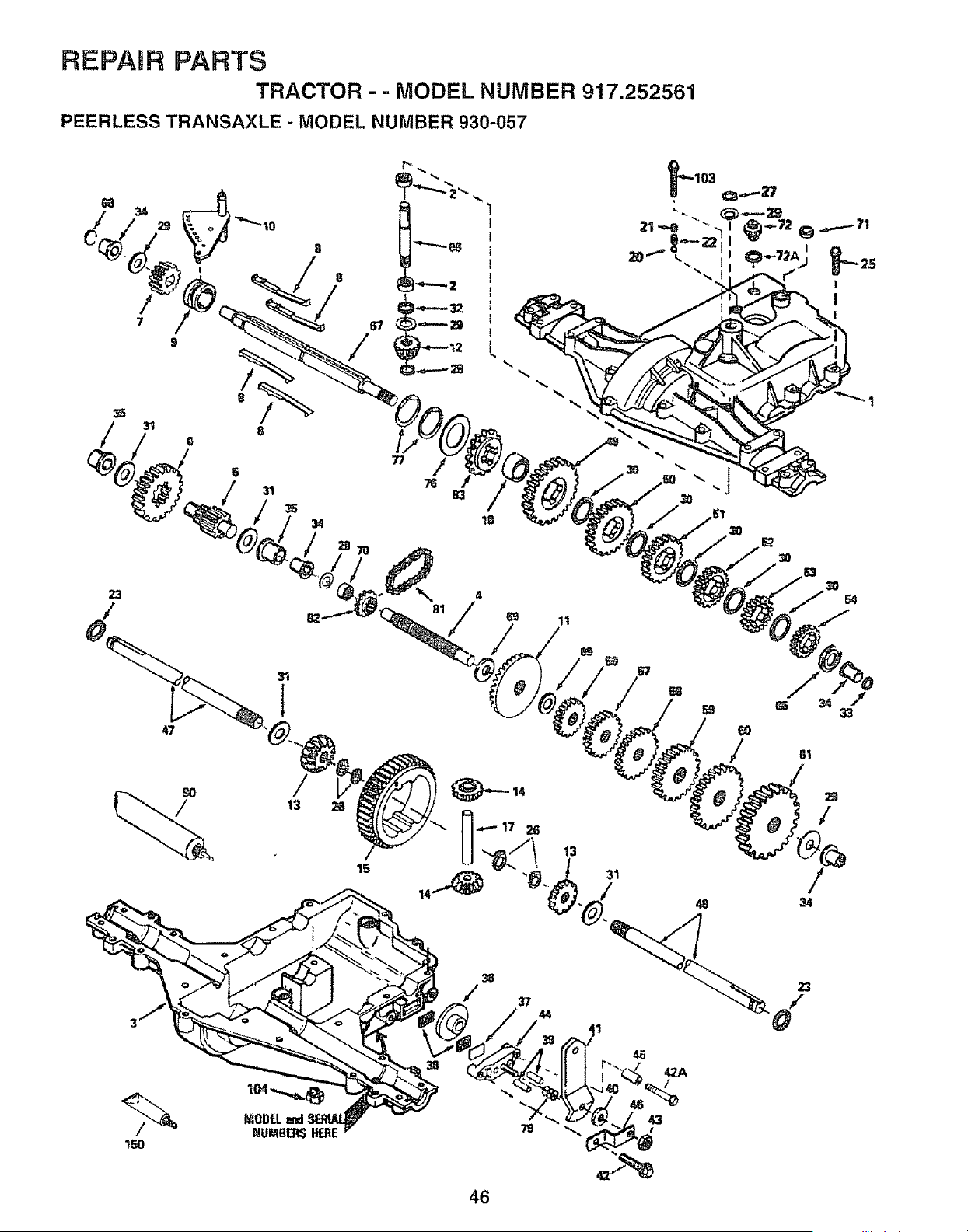
REPAIR PARTS
TRACTOR -- MODEL NUMBER 917.252561
PEERLESS TRANSAXLE - MODEL NUMBER 930-057
5
31
35
34
15
3O
11
61
45
42A
/
43
79
46
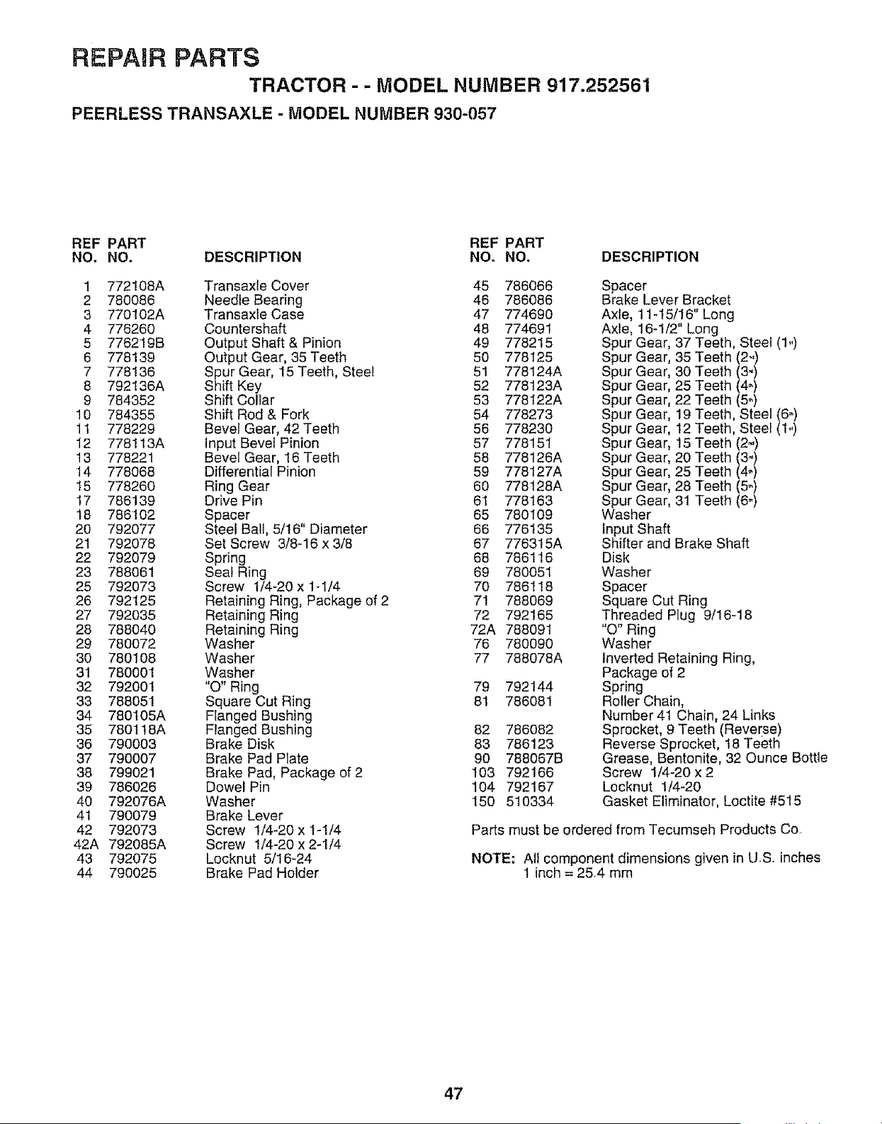
REPAIR PARTS
TRACTOR - - MODEL NUMBER 917.252561
PEERLESS TRANSAXLE - MODEL NUMBER 930-057
REF PART REF PART
NO. NO. DESCRIPTION NO. NO. DESCRIPTION
1 772108A Transaxle Cover 45 786066
2 780086 Needle Bearing 46 786086
3 770102A Transaxle Case 47 774690
4 776260 Countershaft 48 774691
5 776219B Output Shaft & Pinion 49 778215
6 778139 Output Gear, 35Teeth 50 778125
7 778136 Spur Gear, 15 Teeth, Steel 51 778124A
8 792136A Shift Key 52 778123A
9 784352 Shift Collar 53 778t22A
10 784355 Shift Rod & Fork 54 778273
11 778229 Bevel Gear, 42Teeth 56 778230
12 778113A Input Bevel Pinion 57 778151
13 778221 Bevel Gear, 16 Teeth 58 778126A
t4 778068 Differential Pinion 59 778127A
15 778260 Ring Gear 60 778128A
17 786139 Drive Pin 61 778t63
18 786'102 Spacer 65 780109
20 792077 Steel Ball, 5/16" Diameter 66 776t 35
21 792078 Set Screw 3/8-16 x 3/8 67 776315A
22 792079 Spring 68 786116
23 788061 Seal Ring 69 780051
25 792073 Screw 1/4-20 x 1-1/4 70 786118
26 792125 Retaining Ring, Package of 2 7t 788069
27 792035 Retaining Ring 72 792165
28 788040 Retaining Ring 72A 788091
29 780072 Washer 76 780090
30 780108 Washer 77 788078A
31 780001 Washer
32 792001 "O" Ring 79 792144
33 788051 Square Cut Ring 81 786081
34 780105A Flanged Bushing
35 780118A Flanged Bushing 82 786082
36 790003 Brake Disk 83 786123
37 790007 Brake Pad Plate 90 788067B
38 799021 Brake Pad, Package of 2 103 792166
39 786026 Dowel Pin 104 792167
40 792076A Washer 150 510334
41 790079 Brake Lever
42 792073 Screw 1/4-20 x 1-I/4
42A 792085A Screw 1/4-20 x 2-1/4
43 792075 Locknut 5/16-24
44 790025 Brake Pad Holder
Spacer
Brake Lever Bracket
Axle, 11-15/16" Long
Axle, t6-1/2" Long
Spur Gear, 37 Teeth, Steel (1.)
Spur Gear, 35 Teeth (2_)
Spur Gear, 30 Teeth (3-)
Spur Gear, 25 Teeth (4_)
Spur Gear, 22 Teeth (5_)
Spur Gear, 19 Teeth, Steel (6_)
Spur Gear, 12 Teeth, Steel (1.)
Spur Gear, 15 Teeth (2")
Spur Gear, 20 Teeth (3-)
Spur Gear, 25 Teeth (4-)
Spur Gear, 28 Teeth (5_)
Spur Gear, 31 Teeth (6-)
Washer
Input Shaft
Shifter and Brake Shaft
Disk
Washer
Spacer
Square Cut Ring
Threaded Plug 9/16-18
"0" Ring
Washer
Inverted Retaining Ring,
Package of 2
Spring
Roller Chain,
Number 41 Chain, 24 Links
Sprocket, 9 Teeth (Reverse)
Reverse Sprocket, t8 Teeth
Grease, Bentonite, 32 Ounce Bottle
Screw 1/4-20 x 2
Locknut 1/4-20
Gasket Eliminator, Loctite #515
Parts must be ordered from Tecumseh Products Co,
NOTE: All component dimensions given in US., inches
1 inch = 25,4 mm
47
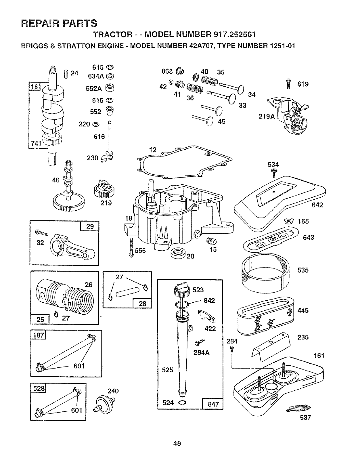
REPAIR PARTS
TRACTOR -- MODEL NUMBER 917.252561
BRIGGS & STRATTON ENGINE - MODEL NUMBER 42A707, TYPE NUMBER 1251-01
601
601
1
15
165
535
523 ........i
i 284 235
T
525
524 O
643
537
642
t61
48
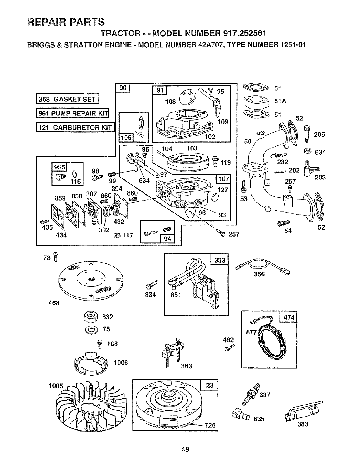
REPAIR PARTS
TRACTOR -- MODEL NUMBER 917,252561
BRIGGS & STRATTON ENGINE - MODEL NUMBER 42A707, TYPE NUMBER 1251-01
t 358 GASKET SE T ]
[861 PUMP REPAIR KI] 1
[121 CARBURETOR KIT
B7
859
901
95
394
108
104 103
102
_119
78
468
434
392
117
334 851
332
Q 75
188
@ 1006
726
93
%_ 257
51
51A
232
_=_ 202
257
54
356
482
337
_635
52
205
634
52
383
49
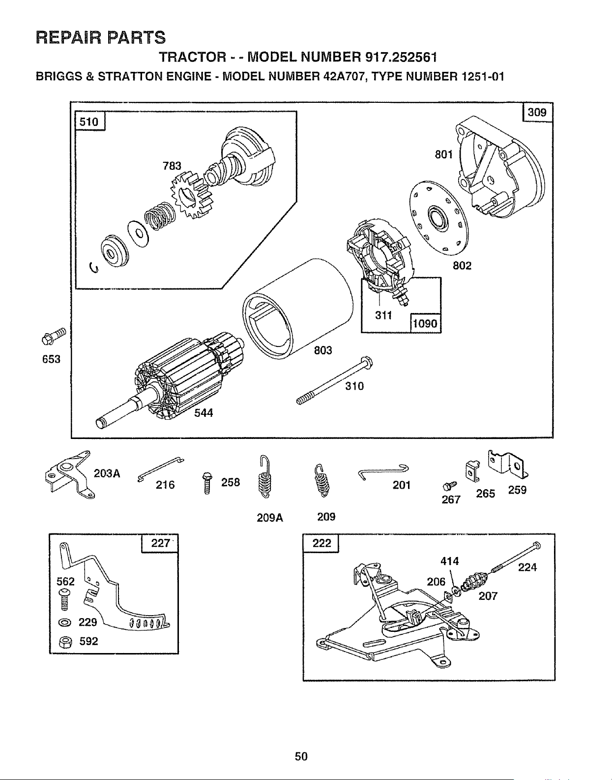
REPAIR PARTS
TRACTOR -- MODEL NUMBER 917.252561
BRIGGS & STRATTON ENGINE - MODEL NUMBER 42A707, TYPE NUMBER 1251-01
_) 229
O 592
783
801
803
802
311
209A 209
201
_' 265 259
267
414
224
206
207
50
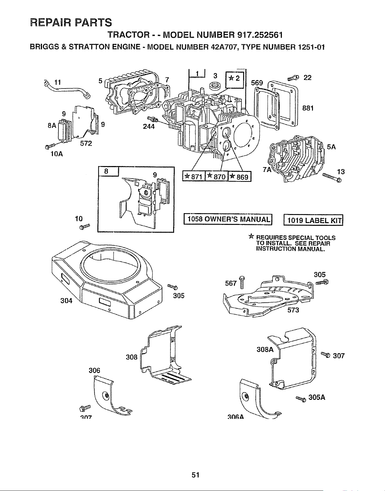
REPAIR PARTS
TRACTOR - - MODEL NUMBER 917.252561
BRIGGS & STRA_ON ENGINE - MODEL NUMBER 42A707, TYPE NUMBER 1251-01
9
8A 9 244
572
10A
10
304
7
3
22
881
[Ios8OWNeR'sM_NUAL]IIO_''_BELK'TI
REQUIRES SPECIAL TOOLS
TO INSTALL. SEE REPAIR
INSTRUCTION MANUAL.
305
305
308
306
"1137
308A
307
305A
51
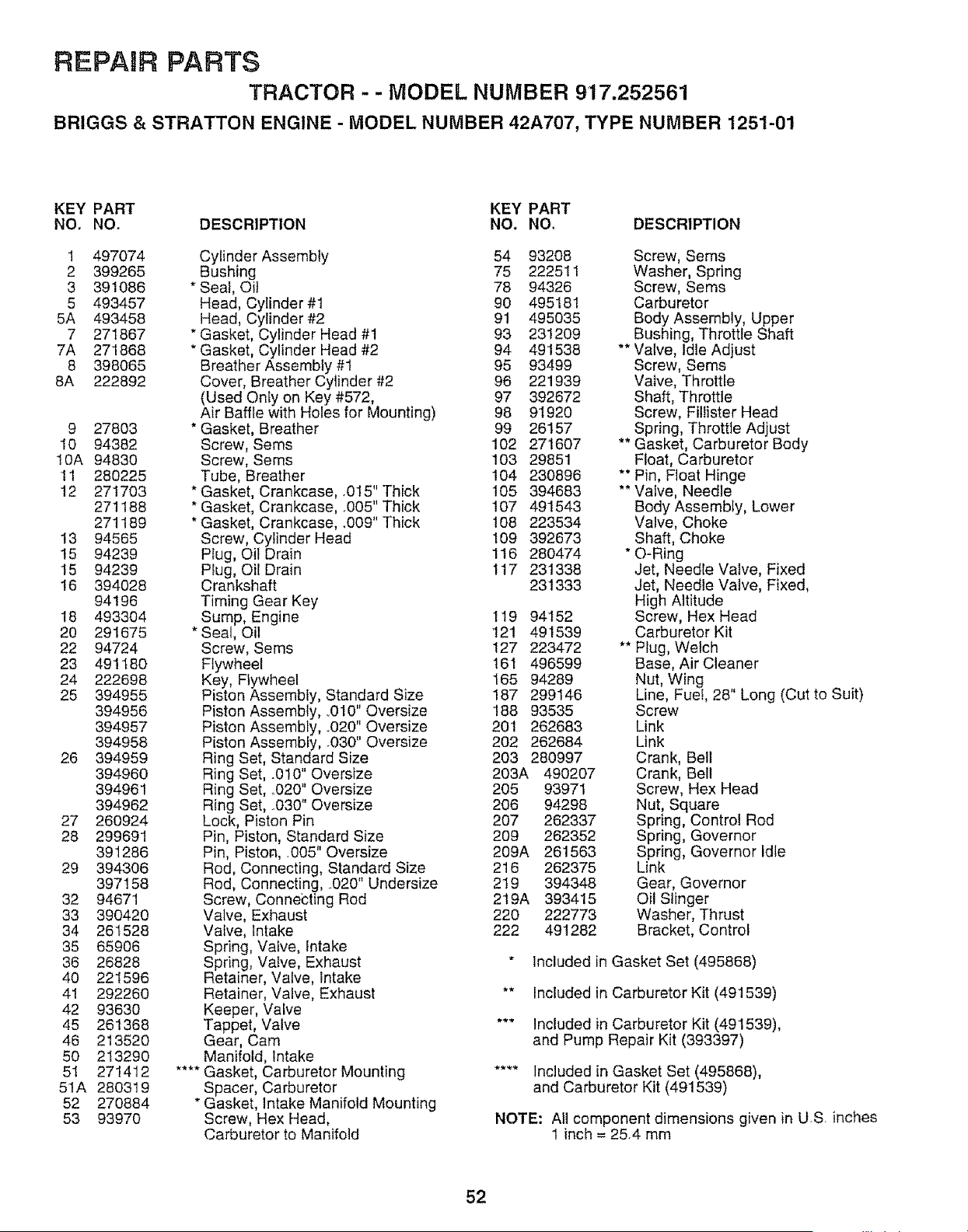
REPAIR PARTS
TRACTOR - - MODEL NUMBER 917.252561
BRIGGS & STRATTON ENGINE - MODEL NUMBER 42A707, TYPE NUMBER 1251-01
KEY PART KEY PART
NO, NO, DESCRIPTION NO. NO. DESCRIPTION
1 497074
2 399265
3 391086
5 493457
5A 493458
7 271867
7A 271868
8 398065
8A 222892
9 27803
10 94382
10A 94830
!1 280225
12 271703
271188
271189
13 94565
15 94239
15 94239
16 394028
94196
18 493304
20 291675
22 94724
23 491180
24 222698
25 394955
394956
394957
394958
26 394959
394960
394961
394962
27 260924
28 299691
391286
29 394306
397158
32 94671
33 390420
34 261528
35 65906
36 26828
40 221596
41 292260
42 93630
45 261368
46 213520
50 213290
51 271412
51A 280319
52 270884
53 93970
Cylinder Assembly 54 93208 Screw, Seres
Bushing 75 222511 Washer, Spring
* Seal, Oil 78 94326 Screw, Sems
Head, Cylinder #1 90 495181 Carburetor
Head, Cylinder #2 91 495035 Body Assembly, Upper
* Gasket, Cylinder Head #t 93 231209 Bushing, Throttle Shaft
* Gasket, Cylinder Head #2 94 491538 ** Valve, Idle Adjust
Breather Assembly #1 95 93499 Screw, Seres
Cover, Breather Cylinder #2 96 221939 Valve, Throttle
(Used Only on Key #572, 97 392672 Shaft, Throttle
Air Baffle with Holes for Mounting) 98 9'I920 Screw, Fillister Head
* Gasket, Breather 99 26157 Spring, Throttle Adjust
Screw, Sems 102 271607 ** Gasket, Carburetor Body
Screw, Sems 103 29851 Float, Carburetor
Tube, Breather 104 230896 ** Pin, Float Hinge
* Gasket, Crankcase, .015" Thick 105 394683 ** Vafve, Needle
* Gasket, Crankcase, ..005" Thick 107 491543 Body Assembly, Lower
* Gasket, Crankcase, _009" Thick 108 223534 Valve, Choke
Screw, Cylinder Head 109 392673 Shaft, Choke
Plug, Oil Drain 116 280474 * O-Ring
Plug, Oil Drain 1t7 231338 Jet, Needle Valve, Fixed
Crankshaft 231333 Jet, Needle Valve, Fixed,
Timing Gear Key High Altitude
Sump, Engine 119 94152 Screw, Hex Head
* Seal, Oil 121 491539 Carburetor Kit
Screw, Sems 127 223472 ** Plug, Welch
Flywheel 161 496599 Base, Air Cleaner
Key, Flywheel 165 94289 Nut, Wing ,
Piston Assembly, Standard Size 187 299146 Line, Fuel, 28' Long (Cut to Suit)
Piston Assembly, ,010" Oversize 188 93535 Screw
Piston Assembly, °020" Oversize 201 262683 Link
Piston Assembly, .030" Oversize 202 262684 Link
Ring Set, Standard Size 203 280997 Crank, Bell
Ring Set, .010" Oversize 203A 490207 Crank, Belt
Ring Set, _020" Oversize 205 93971 Screw, Hex Head
Ring Set, ,030" Oversize 206 94298 Nut, Square
Lock, Piston Pin 207 262337 Spring, Control Rod
Pin, Piston, Standard Size 209 262352 Spring, Governor
Pin, Piston, ,005" Oversize 209A 261563 Spring, Governor Idle
Rod, Connecting, Standard Size 216 262375 Link
Rod, Connecting, ,020" Undersize 219 394348 Gear, Governor
Screw, Connecting Red 219A 393415 Oil Slinger
Valve, Exhaust 220 222773 Washer, Thrust
Vatve, Intake 222 491282 Bracket, Control
Spring, Valve, Intake
Spring, Valve, Exhaust * Included in Gasket Set (495868)
Retainer, Valve, Intake
Retainer, Valve, Exhaust "* Included in Carburetor Kit (491539)
Keeper, Valve
Tappet, Valve *** Included in Carburetor Kit (491539),
Gear, Cam and Pump Repair Kit (393397)
Manifold, Intake
.... Gasket, Carburetor Mounting .... Included in Gasket Set (495868),
Spacer, Carburetor and Carburetor Kit (491539)
* Gasket, Intake Manifold Mounting
Screw, Hex Head, NOTE: All component dimensions given in U-S. inches
Carburetor to Manifold 1 inch = 25.4 mm
52

REPAIR PARTS
TRACTOR - - MODEL NUMBER 917.252561
BRIGGS & STRATTON ENGINE - MODEL NUMBER 42A707, TYPE NUMBER 1251-01
KEY PART KEY PART
NOo NO. DESCRIPTION NO. NO. DESCRIPTION
224 94297 Screw, Pan Head 562 93853 Bolt, Governor Lever
227 491297 Lever Assembly, Governor 567 93777 Screw, Hex Head,
229 222289 Washer Back Plate to Cyiinder
230 223882 Washer, Governor Crank, Inside 569 272645 * Gasket, Base
235 224995 Shield, Fuel Spray 572 224816 Baffle, Air, Cylinder #2
240 394358 Filter, Fuel 573 491304 Plate, Back
244 230318 Connector, Fuel Line 592 92278 Nut, Hex.
257 93897 Screw, Sems 601 93053 Clamp, Hose
258 93949 Screw, Seres 615 94296 Retainer, E-Ring
259 223890 Bracket, CaMe 616 491530 Crank, Governor
265 221535 Clamp, Casing 634 271013 ** Washer, Throttle Shaft
267 94906 Screw, Seres 634A 491287 * Seal, Governor Shaft
284 94264 Screw, Hex Head 635 66538 Boot, Spark Plug
284A 93469 Screw, Hex Head 642 225008 Cover, Air Cleaner
304 495588 Housing, Blower, Red 643 496700 Plate, Air Cleaner
305 94786 Screw, Seres 653 93585 Screw, Hex Head
305A 93343 Screw, Seres 726 391362 Gear, Ring
306 222846 Shietd, Cylinder (Includes Mounting Parts)
306A 223734 Shield, Cylinder 741 262989 Gear, Timing
307 94386 Screw, Self-Tapping 783 280104 Gear, Starter
308 224774 Cover, Air Guide 801 394860 Cap, Drive
308A 224775 Cover, Air Guide 802 497607 Cap, End
309 497596 Motor, Starter 803 497604 Housing, Starter
310 497602 Boft, Thru 819 94675 Screw, Hex Head
3II 497608 Brush Set 842 270920 * Seal, Cap
332 230674 Nut, Hex 847 495715 Tube Assembly, Oil
333 394891 Armature, Magneto 851 221798 Termina!, Cable
334 93381 Screw, Sems 858 270989 *** Diaphragm, Carburetor
337 802592 Plug, Spark 859 271025 *** Gasket, Pump
356 494705 Wire, Stop 860 261358 *** Spring, Diaphragm
358 491856 Gasket Set 861 393397 Repair Kit, Pump
363 19203 Flywheel Puller 868 393606 Seal, Valve
383 89838 Wrench, SparkPlug 869 261463 Seat, Valve, Intake
387 280197 Body, Pump 870 213316 Seat, Valve, Exhaust
392 261395 *** Spring, Diaphragm 871 261961 Bushing, Guide (Exhaust Only)
394 270988 *** Diaphragm, Carburetor 231218 Bushing, Guide (Intake, Brass)
414 220680 Washer 877 393456 Wire, Alternator
422 222875 Bracket, Oil Fli! 881 495901 Plate, Cover
432 221377 *** Cap, Spring 955 397882 Plug and Seal, Solenoid
434 223688 Cover, Diaphragm 1005 281053 Fan, Flywhee!
435 93829 Screw, Diaphragm Cover 1006 224413 Retainer, Fan
445 394019 Filter, Air 1019 496726 Label Kit
468 224521 Screen, Rotating 1058 272112 Owner's Manual
474 393474 Alternator, Dual Circuit 1090 497605 Retainer, Brush
482 93621 Screw, Seres
510 497606 Drive, Starter " lnc!uded in Gasket Set (495868)
523 494947 Cap, Oil Fill
524 271157 * Seal, Fill Tube ** included in Carburetor Kit (491539)
525 495348 Tube, Oil Fill (includes Seals)
528 393815 Pipe, Fuel "** Included in Carburetor Kit (491539),
534 94823 Screw, Air Cleaner and Pump Repair Kit (393397)
535 271271 Filter, Air
537 271411 .... Gasket, Air Cleaner .... Included in Gasket Set (495868),
544 497603 Armature, Starter and Carburetor Kit (491539)
552 262332 Lower Bushing, Governor
552A 262331 Upper Bushing, Governor NOTE: AII component dimensions given in US. inches
556 93585 Screw, Hex Head 1 inch = 25..4 mm
53

SERVICE NOTES
54

SUGGESTED GUIDE FOR S6GHTING SLOPES FOR SAFE OPERATION
O1
O1
SIGHTING
ONLY RIDE UP AND DOWN HILL,
NOT ACROSS HILL
SIGHT AND HOLD THIS LEVEL WITH
SKY LINE OR TREE.
,, ,,,,,,,,,,,
A Operate your Tractor up and down the face of slopes (not
I
,_k greater than 15°), never across the face. Make turns gradu-
1
_ ally to prevent tipping or loss of control. Exercise extreme
caution when changing direction on slopes.

OWNER'S
UAL
MODEL NO.
917.252561
IF YOU NEED
REPAIR SERVICE
OR PARTS:
FOR REPAIR SERVICE, CALL
THiS TOLL FREE NUMBER:
1-800-4-REPAIR
(1-800-473-7247)
FOR REPLACEMENT PARTS
INFORMATION AND
ORDERING, CALL THIS
TOLL FREE NUMBER:
1-800-FON-PART
(1-800-366-7278)
FOR CONSUMER ASSISTANCE
HOT LINE, CALL THIS
TOLL FREE NUMBER:
1-800-659-5917
®
19 HP TWIN CYLINDER
ELECTRIC START
3 in One Convertible
42" MOWER
6 SPEED TRANSAXLE
LAWN TRACTOR
Each tractor has its own model number Each engine has
its own model number.
The model number for your tractor will be found on the
_odel plate located under the seat.
The model number for your engine will be found on the
blower housing of the engine
All parts listed herein may be ordered from any Sears,
Roebuck and Co, Service Center/Department and most Re-
tail Stores
WHEN ORDERING REPAIR PARTS, ALWAYS GIVE THE
FOLLOWING INFORMATION:
PRODUCT - TRACTOR
• MODEL NUMBER - 917.252561
• ENGINE MODEL NO.._ 42A707, TYPE NO. 1251-01
• PART NUMBER
• PART DESCRIPTION
Your Sears merchandise has added value when you
consider Sears has service units nationwide staffed with
Sears trained technicians._o professional technicians
specifically trained to insure that we meet our ptedge to
you, we service what we sell.
150331 06.23°95 KFSW Printed in U.SoA.


