Loading ...
Loading ...
Loading ...
I "Jllll+[_ :11:ts]lJl I1: =i :r_*!:j
The router accessory Converts your Cutting Tool into a
small hobby plunge router that iscapable of handling
small _" shank router bits as well as the spiral cutting bit.
The tiltingbase is ideal for bevel cutting. The plunge
feature allows you to pre-set up to three different cutting
depths.
IA,WARNS"G1
Unplug the tool from the power source before
changing accessories, changing bits and making
adjustments.
Before turning the tool ON, check to make sure the
bit and all accessory fasteners are securely
tightened.
ROUTER ACCESSORYINSTALLA_ON
1, Remove any occesso_ already installed on the tool
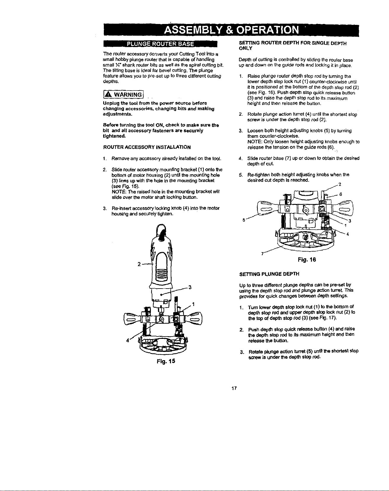
2. Slide router acceesory mounting bracket (1) onto the
bottom of motor housing (2) until the mounting hole
(3) lices up with the hole in the mounting bracket
(see Fig. 15).
NOTE: The raised hole in the mounting bracket will
slide over the motor shaft locking button.
3. Re-insert accessory locking )mob (4) into the motor
housing and securely tighten.
SETTING ROUTER DEPTH FOR SINGLE DEPTH
ONLY
Depth of cutting is controlled by sliding the muter base
up and down on the guido rods and locking it in place.
1.
Raise plunge router depth stop rod by turning the
lower depth stop look nut (1) counter-clockwise until
it is positioned at the bottom of the depth stop rod (2)
(see Fig. "t6). Push depth stop quick release button
(3) and raise the depth stop rod to its maximum
height and then release the button.
2. Rotate plunge action turret (4) untilthe shortest stop
screw is under the depth stop rod (2).
3.
Loosen both height adjusting knobs (5) by turning
them counter.clookwise.
NOTE: Only loosen height adjusting knobs enough to
release the tension on the guide rods (6).
Slide router base (7) up or down to obtain the desired
depth of cut,
5. Re-tighten both height adjusting knobs when the
desired cut depth is reached.
Fig. 15
Fig. t6
SE'I'flNG PLUNGE DEPTH
Up to three different plunge depths c_n be preset by
using the depth stop rod and plunge sction turret, This
provides for quick changes between depth settings.
1. Turn lowerdepthstoplock nut(1) to the bottomof
depthstop rodand upperdepthstoplock nut (2) to
the topofdepthstoprod(3) (see Fig.17).
2. Push depth stop quick release button (4) and raise
the depth stop rod to its maximum height and then
relerase the button.
3. Rotateplungeactionturret (5) unBthe shorteststop
screwIsunderthe depthstoprod.
17
Loading ...
Loading ...
Loading ...