Loading ...
Loading ...
Loading ...
_HI:._]m::l'_o41JW|l_[_[eLWlle]
CIRCLE CUTTING GUIDE OPERATFON
),A WARNING I
Unplug the tool from tt3epower source before
changing accessories, changing bits and making
adjustments.
Before turning the tool ON, check to make sure bit
and all accessory fasteners are securely tightened.
1. Mark the centre of the circle you wish to cut on the
workpiece and drill a 6 mm or 151_"pilot hole.
2. Adjust Guttingbit depth to 118"longer than the
thickness of the material being cut (see Fig. 5).
3. Adjust the circle cutting guide radios by loosening
pivot point knob, sliding it to the correct circle radius
and re-tightening in the desired location.
NOTE: Check circre cutting guide radius setting by
measuring from the pivot point to the outside of the
spiral bit.
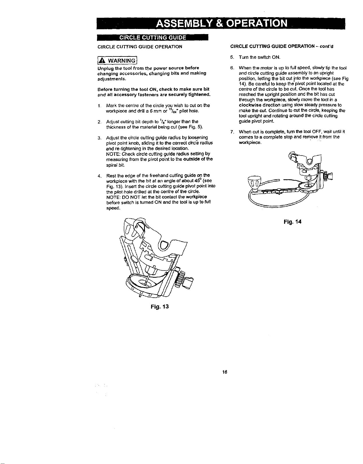
4. Rest the edge of the freehand cuffing guide on the
workp=ece wuththe b t at an angle of about 45 (see
Fig, 13)• Insert the circle cutting guide pivot point into
the pilot hole drilled at the centre of the circle.
NOTE: DO NOT let the bit contact the workpiece
before switch is turned ON and the tool isup to furl
speed.
Fig. 13
CIRCLE CUTTING GUIDE OPERATION - cont'd
5. Turn the switch ON.
6.
7.
When the motor is up to fullspeed, slowly tip the tool
and circle cutting guide assembly to an Upright
position, letting the bit cut nte the workpiece (see Fig
f4J. Be careful to keep the p vo point ocated at the
centre of the circle to be cut. Once the tool has
reached the upright position and the bit has cut
through the workpiece, slowly move the tool in a
clockwise direction using slow steady pressure to
make the cut. Continue tocut the circle, keeping the
tool upright and rotating around the circle cutting
guide pivot point.
When cut is complete, turnthe tool OFF, wait until it
comes to a complete stop and remove it from the
workpiece.
Fig. 14
16
Loading ...
Loading ...
Loading ...