Loading ...
Loading ...
Loading ...
8
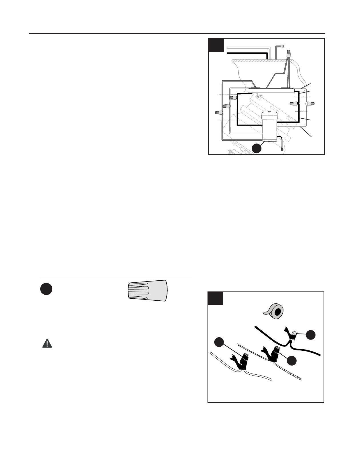
WIRING
1.
Wire Connector x 3
Hardware Used
AA
Make the necessary wiring connections for
remote control operation as detailed below and
in the figure. For each wire connection, use one
of the wire connectors (AA), (L), making sure to
screw wire connector on in a clockwise
direction.
CAUTION: Assistance from another person is
recommended for this step.
Connect all GROUND (GREEN) wires together
from fan and mounting plate (A) to
BARE/GREEN supply wire from ceiling.
Connect BLACK wire (labeled AC IN L) from
remote control receiver (M) to BLACK supply
wire from ceiling.
Connect WHITE wire (labeled AC IN N) from
remote control receiver (M) to WHITE supply
wire from ceiling.
Connect WHITE wire (labeled TO MOTOR N)
from remote control receiver (M) to WHITE wire
from motor housing (D).
Connect BLACK wire (labeled TO MOTOR L)
from remote control receiver (M) to BLACK wire
from motor housing (D).
Connect BLUE wire (labeled FOR LIGHT) from
remote control receiver (M) to BLUE wire from
motor housing (D).
Wrap electrical tape around each individual wire
connector (AA), (L) down to the wire.
WARNING: Make sure no bare wire or wire
strands are visible after making connections.
Place green and white connections on opposite
side of box from the black and blue (if applicable)
connections.
Turn spliced/taped wires upward and gently push
wires and wire connectors into outlet box.
2.
2
AA
AA
AA
M
1
WHITE SUPPLY WIRE
BLACK SUPPLY WIRE
BLACK
BLACK
WHITE
BLUE
BLUE
WHITE
BLACK
AC IN L
WHITE
AC IN N
WHITE
GROUND (GREEN OR BARE)
GROUND
(GREEN OR BARE)
BLACK
FROM
RECEIVER
FROM
FAN
FROM
RECEIVER
FROM
CEILING
Loading ...
Loading ...
Loading ...