OWNER'S MANUAL

CAUTION
RISKOFELECTRICSHOCK
DONOTOPEN
CAUTION: TO REDUCE THE RISK OF
ELECTRIC SHOCK, DO NOT REMOVE
COVER (OR BACK). NO USER-SERVICEABLE
PARTS INSIDE. REFER SERVICING TO
QUALIFIED SERVICE PERSONNEL.
• Explanation of Graphical Symbols
The lighming flash with arrowhead symboh wilhin an
equilateral triangle, is imended 1o alerl you to the
prescnce of uninsulated "dangerous voltage" wilhin
lhe producl_s enclosure lhal may be of sufficient
magnitude to conslitute a risk of electric shock to
persons,
The exclanlation poinl within an equilateral triangle
is inlended to alert you to lhe presence of important
operating and maimenance (sel_'icing) instruclkms in
the literature accompanying the appliance,
1 Read Instructions All the safety and operating instructions
should be read belore the product is operated.
2 Retain Instructions The safety and operating instructions
should be retained lk_rluture rel-ereuce.
3 Heed Warnings All warnings on the product and in the
operating instructions should be adhered to.
4 Follow Instructions All operating and use instructions
should be followed.
5 Cleaning Unplug this product fi'om the wall outlet before
cleaning. Do not use liquid cleaners or aerosol cleaners.
6 Attachments Do not use attachments not recommended by
the product manulhcmrer as they may cause hazards.
7 Water attd Moisture Do not use this product near water
for example, near a bath tub. wash bowl. kitchen sink. or
laundry tub: in a wet basement: or near a swimming pool:
and the like.
8 Accessories Do not place this product on an unstable cart.
stand, tripod, bracket, or table. The product may f:dh
causing serious it_iury to a child or adult, and serious
damage to the product. Use only with a cart. stand, tripod,
bracket, or table recommended by the manulhcmrer, or sold
with the product. Any mounting of the product should
follow the manulhcturer's instructions, and should use a
mounting accessory recommended by the manufacturer.
9 A product and cart combination should be moved with care.
Quick stops, excessive lbrce, and uneven surlaces may
cause the product and cart combination to
overturn.
10 Ventilation Slots and openings in the cabinet are provided
lor ventilation attd to ensure reliable operation of the
product and to protect it from overheating, and these
openings must not be blocked or covered. The openings
should never be blocked by placittg the product on a bed.
solid, rug, or other similar surface. This product should not
be placed in a builtdn installation such as a bookcase or rack
unless proper ventilation is provided or the manufacturer's
instructions hme been adhered to.
11 Power Sources This product should be operated only from
the type of power source indicated on the marking label. If
you are not sure of the type of power supply to your home.
consult your product dealer or local power company. For
products intended to operate from battery power, or other
sources, refer to the operating instructions.
12 Grounding or Polarization This product may be equipped
with a polarized alternating current line phtg (a plug having
one blade wider than the other). This plug will fit into the
power outlet only one way. This is a safety feature. If you
are unable to insert the plug fully into the outlet, try
reversing the plug. If the plug should still fail to fit. contact
your electrician to replace your obsolete outlet. Do not
defeat the safety purpose of the polarized plug.
13 Power-Cord Protection Power-supply cords should be
routed so that they are not likely to be walked on or pinched
by items placed upon or against them, paying particular
attention to cords at plugs, convenience receptacles, and the
point where they exit from the product.
14 Lightning For added protection lor this product during a
lightning storm, or when it is left unattended and unused for
long periods of time. unphtg it trom the wall outlet attd
disconnect the antenna or cable system. This will prevent
damage to the product due to lightning and power-line
surges.
1S Power Lines An outside antenna system should not he
located in the vicinity of overhead power lines or other
electric light or power circuits, or where it can fall into such
power lines or circuits. When installing an outside autmma
system, extreme cltre should be taken to keep from touching
such power lines or circuits as contact with them might be
latah
16 Overloading Do not overload wall outlets, extension
cords, or integral convenience receptacles as this can result
in a risk of fire or electric shock.
17 Ot_ject and Liquid Entry Never push objects of arty kind
into this product through openings as they may touch
dangerous voltage points or short-out parts that could result
in a fire or electric shock. Never spill liquid of any kind on
the product.
18 Servicing Do not attempt to service this product yourself
its opening or removing covers may expose you to
dangerous voltage or other hazards. Refer all servicing to
qualified service personnel.
19 Damage Requiring Service Unplug this product from the
wall outlet and refer servicing to qualified service personnel
under the lollowiug conditions:
a) When the power-supply cord or plug is damaged,
b) If liquid hits been spilled, or ot_iects haxe fallen into the
product.
c) If the product hits been exposed to rain or water.
Caution-i

d) If the product does not operate normally by following 24
the uperating instructions. Adjust unly those controls
that are covered by the operating instructions as an
improper adjustment of other controls may result in
damage and will often require extensive work by a
qualified technician to restore the pruduct to its normal
operation.
e) If the product has been dropped or damaged in any
way, and
f) When the pruduct exhibits a distinct change in perfor-
mance - this indicates a need fl+rservice.
20 Replacement Parts When replacement parts are required.
be sure the service technician has used replacement parts
specified by the manuDcturer or haxe the same
characteristics as the urigiual part. Unauthorized
substitutions may result in fire. electric shock, or other
hazards.
21 Safety Check Upon completion ol any service ur repairs to
this product, ask lice service lechuician Io perlornc safety /-f
checks Io determine Ihal Ihe product is in pruper operating
condition. /"
22 Wall ur Ceiling Mounting The unit should be mounted
to a wall or ceiling only as recommended by the
maRclfactclrer.
ELEOTIqlC
23 Heat The product should be situated away fi'om heal SERWCE
sources such as radiators, heat registers, stuves, ur other
products (including amplifiers) that produce heat.
Note to CATV system installer:
This reminder is provided to call the CATV system
installer's attention to Article 820-40 of the NEC that
provides guidelines for proper grounding and, in
particular, specifies that the cable ground shall be
connected to the grounding system of the building, as
close to the point of cable entry as practical.
Outdoor Antenna Grounding If an outside antenna or
cable system is connected tu the product, be sure the antmma
or cable system is grounded so as to provide some
protection against voltage surges and built-up static charges.
Article 810 of the National Electrical Code. ANSI/NFPA 7(1.
provides infonnatiun with regard to proper grounding of the
mast and supporting structure, grounding of the lea&in wire
to an antenna discharge unit. size of grounding cunductors.
locatiun of antenna discharge unit. cunuection to grounding
electrudes, and requirements for the grounding electrode.
EXAMPLE OF ANTENNA GROUNDING
(NEC SECTION 810_0)
(NEC SECTION 810_1)
NEC NATIONAL ELECTRICALCODE
ELECTRODE SYSTEM
(NEC ART 25O PARTH)
FCC INFORMATION (for US customers)
1 IMPORTA.NT NOTI(-E: DO NOT MODIFY THIS
UNIT!
This product, when installed as indicated in the
instructions cuntained in this manual, meets FCC
requirements. Modificatiuns not expressly approved by
Yamaha may void yuur authority, granted by the FCC. to
use the product.
IMPORTANT: When connecting this product to
accessuries and/or another pruduct use only high quality
shielded cables. Cahlc/s supplied with this product MUST
be used. Follow all installation instructions. Failure to
fl)llow instructions could void your FCC authorization tu
use this pruduct in the USA.
NOTE: This product has been tested and found to comply
with the requirements listed in FCC Regulations. Part 15
lot Class "B" digital devices. Compliance with these
requirements provides a reasonable level uf assurance thai
your use of this product in a residential environment will
not result in harmlul interference with other electrunic
devices.
This equipment generates/uses radio li'equencies and. if
not installed and used according to the instructions fuund
in the users manual, may cause interference harmlul to the
operation of other electronic devices.
Compliance with FCC regulations does not guarantee that
interli_rence will not uccur in all installations. If this
product is louud to he the source of interference, which
can be determined by turning the unit "OFF" and "ON".
please try to eliminate the problem by using one of the
following measures:
Relocate either this product or the device that is being
affected by the interlcrence.
Utilize puwer outlets that are on dilti_rent branch (circuit
breaker ur flise) circuits or install AC line filter/s.
In the case of radio or TV interference, relucate/reurient
the antenna. If the antenna lead-in is 30(1 uhm ribbon lead.
change the leadqn to cuaxial type cable.
If these corrective measures do not produce satislactory
results, please contact the lucal retailer mlthorized to
distribute this type of product. If you can not locate the
appropriate retailer, please contact Yamaha Electrunics
Corp.. U.S.A. 6660 Orangethorpe Ave.. Buena Park. CA
90620.
The above statements apply ONLY to those products
distributed by Yamaha ( orporation of America or its
subsidiaries.
Caution-ii
1 To assure the finest performance, please read this manual
carefully. Keep it in a safe place for future reference.
2 Install this sound system in a well retaliated, cool. dry, clean
place away t'rom direct sunlight, heat sources, vibration.
dust. moisture, and/or cold. Allow ventilation space of at least
30 cm on the top, 20 cm on the lell and right, and 20 cm on
the back of this unit.
3 Locate this unit away from other electrical appliances, motors.
or transformers to avoid humming sounds.
4 Do not expose this unit to sudden temperature changes lhom
cold to hot. and do not locate this unit in an mwironment with
high humidity (i.e. a room with a humidifier) to prevent
condensation inside this unit. which may cause an electrical
shock, fire. damage to this unit. and/or personal injury.
5 Avoid installing this unit where loreign ohjects may fall onto
this unit and/or this unit may be exposed to liquid dripping or
splashing. On the top of this unit. do not place:
Other components, as they may cause damage and/or
discoloration on the surface of this unit.
Burning ot_jects (i.e. candles), as they may cause fre.
damage to this trait, and/or personal injury.
Containers with liquid in them. as they may fall and liquid
may cause electrical shock to the user and/or damage to
this unit.
6 Do m)t cover this unit with a newspaper, tablecloth, curtain.
etc. in order not to obstruct heat radiation. If the temperature
inside this unit rises, it may cause fire. damage to this unit.
and/or personal il_jury.
7 Do not plug in this unit to a wall outlet tmtil all connections
are complete.
8 Do not operate this unit upside-down. It may overheat.
possibly causing damage.
9 Do not use lorce on switches, knobs and/or cords.
10 When discommcting the power cable from the wall outlet.
grasp the plug; do not pull the cable.
11 Do not clean this trait with chemical solvents: this might
damage the finish. Use a clean, dry cloth.
12 Only voltage specified on this unit must be used. Using this
unit with a higher voltage than specified is dangerous and may
cause fire, damage to this unit. and/or personal injury. Yamaha
will I_otbe held responsible lot any damage resulting from use
of this unit with a voltage other than specified.
13 To prevent damage by fghtning, keep the power cord and
outdoor antelmas disconnected lrom a wall outlet or the unit
during a lightning storm.
14 Do not attempt to modil} or fix this unit. Contact qualified
Yamaha service personnel when any service is needed. The
cabinet should never be opened lk_rany reasons.
15 When not planning to use this unit fw long periods of time
(i.e. vacation), disconnect the AC power plug lhom the wall
outlet.
16 Install this unit near the AC outlet and where the AC power
plug can be reached easily.
17 Be sure to read the "TROUBLESHOOTING" section on
common operating errors belore concluding that this unit is
faulty.
18 Belore moving this unit, press MASTER ON/OFF to release it
outward to the OFF position to turn off this unit. and then
disconnect the AC power plug from the AC wall outlet.
19 VOLTAGE SELECTOR (Asia and Genera] models only)
The VOLTAGE SELECTOR on the rear pane] of this unit
must be set for your local main voltage BEFORE plugging
into the AC wall outlet. Voltages are:
Asia model ............................ 2201230 240 V AC. 50160 Hz
General model ........ 1101120/2201230 240 V AC. 50160 Hz
20 The batteries shall not be exposed to excessive heat such as
sunshine, fire or like.
WARNING
TO REDUCE THE RISK OF FIRE OR ELECTRIC
SHOCK, DO NOT EXPOSE THIS UNIT TO RAIN
OR MOISTURE.
As long as this unit is connected to the AC wall outlet,
it is not disconnected from the AC power source even
if you turn offthis unit by MASTER ON/OFF. In this
state, this unit is designed to consume a very small
quantity of power.
FOR CANADIAN CUSTOMERS
To prevent electric shock, match wide blade of plug to
wide slot and fully insert.
This Class B digital apparatus complies with Canadian
ICES-003.
POUR LES CONSOMMATEURS CANADIENS
Pour (viter les chocs _lectriques, iutroduire la lame la
plus large de la fiche duns ht borne correspondante de
lu prise et pousser jusqu'au fond.
Cet appareil numdrique de la classe Best conforme :_
la norme NMB-003 du Canada.
IMPORTANT
Please record the serial number of this unit in the space
below.
MODEL:
Serial No.:
The serial number is located on the rear of the unit.
Retain this Owner's Manual in a safe place for future
reference.
Caution-iii

Notice ....................................................................... 2
Features ................................................................... 3
Supplied accessories .................................................. 3
Getting started ........................................................ 4
Quick start guide .................................................... 5
Connections ........................................................... 11
Optimizing the speaker setting
for your listening room .................................... 28
Using AUTO SETUP .............................................. 28
j
Selecting the SCENE templates ........................... 33
Selecting the desired SCENE template .................... 33
Creating your original SCENE templates ................ 36
Playback ................................................................ 37
Basic procedure ....................................................... 37
Selecting the MULTI CH INPUT conlponent ......... 38
Selecting the front speaker set ................................. 38
Selecting audio input jacks (AUDIO SELECT) ...... 39
Displaying the current status of this unit
oil a video monitor ............................................... 39
Using your headphones ............................................ 40
Muting the audio output ........................................... 40
Playing video sources
in the background of an audio source .................. 40
Displaying the input source iolormatiou ................. 40
1Jsing the sleep timer ............................................... 41
Sound field programs .......................................... 42
Selecting sound field programs ............................... 42
Sound field program descriptions ............................ 42
El_joyiug unprocessed input sources
(Straight decoding mode) .................................... 47
Using audio features ............................................. 48
Enjoying pure hiq'i sound ........................................ 48
Adjusting the tonal quality ....................................... 48
Adjusting the speaker level ...................................... 48
Enjoying multi-channel sources
in 2-channel stereo ............................................... 49
Selecting the night listening mode ........................... 49
FM/AM tuning ...................................................... 51t
Automatic tuning ..................................................... 50
Manual tuning .......................................................... 50
Automatic preset tuning ........................................... 51
Manual preset tuning ............................................... 51
Selecting preset stations ........................................... 52
Exchanging preset stations ...................................... 52
XM Satellite Radio tuning ................................... 53
Connecting the XM Mini-Tuner Dock .................... 53
Activating XM Satellite Radio ................................ 54
Basic XM Satellite Radio operations ....................... 54
Setting the XM Satellite Radii) preset ch:mnels ...... 56
Displaying the XM Satellite Radio information ...... 57
[?sing iPod TM .......................................................... 58
Controlling iPod':" ................................................... 58
Recording .............................................................. 60
Advanced sound configurations ........................... 61
Changing sound field parameter settings ................. 61
Selecting decoders ................................................... 66
Customizing this unit (MANUAL SETUP) ......... 69
Using SET MENU ................................................... 71
1 SOUND MENU .................................................... 72
2 INPUT MENU ...................................................... 78
3 OPTION MENU ................................................... 81
Remote control features ........................................ 84
Using the remote control
liarthe SCENE ligature......................................... 84
Controlling this unit, a TV,
or other components ............................................ 85
Setting remote control codes ................................... 87
Resetting all remote c/mtrol codes ........................... 88
[?sing multi-zone configuration ............................ 89
Connecting Zone 2................................................... 89
Controlling Zone 2 ................................................... 90
Advanced setup ...................................................... 92
Using the advanced setup ........................................ 92
*_D @ * $= * @
Troubleshooting ..................................................... 96
Resetting the system ............................................ 103
Glossary ................................................................ 104
Sound field program information ...................... 106
Parametric equalizer information ..................... 107
Specifications ....................................................... 108
Index ..................................................................... 110
(at the end of this manual)
Front panel ................................................................ i
Remote control ....................................................... ii
List of remote control codes ................................. iii
"@SPEAKERS" or "@ DVD" (example) indicates the
name of the parts on the fi'ont panel or the remote controh
Refer to the attached sheet or the pages at the end of this
manual for the information about each position of the parts.
11
1En

About this manual
• -",;"-indicates a tip fl)r your operation.
• Some uperatious can be performed by using either the
buttons uu the flout panel or the ones on the remote
contruh In case the button names dit'li:r between the l?ont
panel and the remote contrul, the button name (m the
remote control is given in parentheses.
• This manual is printed prior to production. Design and
specifications are subject to change in part as a result of
improvements, etc. In case of differences between the
manual and product, the product has priority.
• "@ SPEAKERS" or "@ DVD" (example) indicates the
name uf the parts on the front panel or the rcmute controh
Relcr to the attached sheet ur the pages at the end of this
manual for the information about each position of the
parts.
• The symbol "_, " with page number(s) indicates the
corresponding reference page(s).
We Want You Listening For A Lifetime
Yalnaha and the Electronic Industries Association's
Consun_er Electronics Group want you to get the
most out ofyottr equipment by playing it at a safe
leveh One that lets the sound come through loud and
_,_,_._LISTENI_Gclear without annoying_ blarin_ or distortion and,
most importantly, without affecting yottr sensitive
hearing. Since hearing damage fi:om loud sounds is often
undetectable until it is too late. Yamaha and the Electronic
Industries Association's Consumer Electronics Group
recomlnend you to avoid prolonged exposure from excessive
volmne lex els.
DIGITAL.EX
Manufactured under license frum Dulby Laburatories.
"Dulby". "Pru Logic". and Ihe double-D symbol are trademarks
171Dolby Laboraluries.
_dl-tS
DTS_ES [NEO:6196/24. Product "DTS" and "DTS-ES INEO:6"
are registered trademarks of DTS. lnc.
"96/24" is a trademark of DTS. Inc.
iPodTM
"iPud" is a tradmnark t)1 Apple Computer. Inc.. registered in the
U.S. and other countries.
H mr
"HDMI". the "HDMI" logo and "High-Definition Multimedia
lnterlbce" are trademarks or registered trademarks of HDMI
Licensing LLC.
SILENT TM
CINEMA
"SILENT CINEMA" is a trademark uf YAMAHA
CORPORATION.
,XN 7! XM MiniorunEr
The XM name and related logos are registered trademarks 01XM
Satellite Radiu Inc.
neural
SURROUNO
Nmlral Surro/lnd rxl name :rod related lugos are trademarks owue(l
by Neural Audio Corporation.
2 En

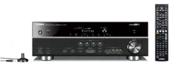
Built-in 7-channel power amplifier
• Miuimuna RMS uutput pu'_rer
(20 Hz to 20 kHz, 0.06% THD, 8 _--))
Front: 90 W + 90 W
Center: 90 W
Surround: 90 W + 90 W
Surround back: 90 W + 9(1W
SCENE function
• 18 preset SCENE templates l_r _arious situations
• 4 original SCENE templates lk)r customizing capability
• Controlling Yamaha SCENE control signal support
component (some models only) working with the SCENE
flmction
Sound field programs
• Proprietary Yamaha technolog_ lot the creation of s(mnd
fields
• Compressed Music Enhancer mode to improve the somld
quality of compression artifacts (such as the MP3 format) to
that of a high-quality stere()
• Dolby Digital/Dolby Digital EX decoder
• DTS/DTS-ES Matrix. Discrete. DTS Neu:6.
DTS 96124 decoder
• Dolby Pro Logic/Dolby Pro Logic II/Dolby Pro Logic llx
decoder
• Neural Surround decoder
• Virtual CINEMA DSP
• SILENT CINEMA
Sophisticated FM/AM tuner
• 40-stafion random and direct preset tuning
• Automatic preset tuning
• Preset station shifting capability (preset editing)
XM Satellite Radio
• XM Satellite Radio tuning capahilit_ (using the "XM Mini-
Tmmr Dock" sold separately)
• Neural Surround decoder to play back the XM HD content of
XM Satellite Radio broadcasts in multi-chammls, resulting in
a lull surround sound experience
• XM Satellite Radio information displaying capability
HDMI (High-Definition Multimedia Interface)
• HDMI interface lot standard, enhanced or high-definition
video (inchldes 1080p vide() signal transmission) as well as
multi-channel digital audiu based on HDMI version 1.2a
iPod controlling capability
• DOCK termilml tu connect a Y:mmha )Pod unixersal dock
(such as the YDS-IO, sold separately), which supports )Pod
(Click and Wheel), )Pod nanu, and )Pod mini
• Playback information displaying capability
• Battery charging capability
Other features
• YPAO (Y:mmha Parametric Room Acoustic Optimizer) for
automatic speaker setup
• 192-kHz/24-bit D/A converter
• OSD (on-screen display) menus that allow you to optimize
this unit to suit your individual audiovisual system
• 5.1 or 7. l-channel additional input.jacks lbr discrete multi-
chalmel input
• S-video signal input/output capability
• Component video inpuffuutput capability includes
(3 COMPONENT VIDE() INs and 1MONITOR OUT)
• Digital video signal conversion (composite video ++ S-video
> component vide()) capability for monitor out
• Optical and coaxial digital audio signal .jacks
• Pure Direct mode lor pure hi-fi sound for all sources
• Cinema and music night listening modes
• Remote control with preset remote control codes capability
• Zone 2 custom installation lacility
• Zone switching capability between the main zone and Zone 2
using ZONE CONTROL
• Bi-amplificatiun connection capability
• Sleep timer
Check that you received all of the following parts.
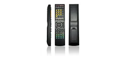
Remote control Batteries (2)
(AA, R6, UM-3)
Optimizer microphone
The lorm of the supplied accessuries varies depending on the models.
AM loop antenna
Indoor FM antenna
3 En

• Installing batteries in the remote control
@
1
2
Take off the battery compartment cover.
Insert the two supplied batteries
(AA, R6, UM-3) according to the polarity
markings (+ and -) on the inside of the
battery compartment.
Snap the battery compartment cover back
into place.
• Change all of the batteries if you notice the following
c(mditions:
the operation range of the remote control decreases.
the @TRANSMIT indicator does not flash or its light
becomes dim.
• Do not use an old battery together with a new one.
• Do not use dil]i_rent types of batteries (such as alkaline and
manganese batteries) together. Read the packaging carefully as
these different types of batteries may have the same shape and
color.
• lfthe batteries have leaked, dispose of thmn immediately. Avoid
touching the leaked material or letting it come into contact with
clothing, etc. Clean the battery compartmm]t thoroughly before
installing new batteries.
• Do not throw away batteries with general house waste: dispose
of them correctly in accordance with your local regulations.
• If the remote control is without batteries for more than 2
minutes, or if exhausted batteries remain in the rmnote control.
the ccmtents of the memory may be cleared. When the mmnory
is cleared, insert new balteries, set up the rmnote control code
and program any acquired functions that may have been
cleared.
• VOLTAGE SELECTOR
(Asia and General models only)
The VOLTAGE SELECTOR on the rear panel of
this unit must be set for your local voltage
BEFORE plugging the power cable into the AC
wall outlet. Improper setting of the VOLTAGE
SELECTOR may cause damage to this unit and
create a potential fire hazard.
Rotate the VOLTAGE SELECTOR clockwise or
counterclockwise to the correct position using a
straight slot screwdriver.
Voltages are as follows:
Asia model ......................... 2201230-240 V AC, 50160 Hz
General model ...... 1101120/2201230_40 V AC, 50160 Hz
_==== VOLTAGE
SELECTOR
.........Voltage indication
4 En

The following steps describe the easiest way to enjoy DVD movie playback in your home theater.
Video monitor
Front left
speaker
Front right
speaker
Subwoofer
Surround right
speaker
In these steps, you need the following supplied
accessories.
AM loop antenna
Indoor FM antenna
speaker
DVD player
Surround left
speaker
Surround back
right speaker
Surround backleft
speaker
The t_llowing items are not included in the package of this
unit.
Speakers
Front speakers .................................... 2
Center speaker ................................... 1
Surround speakers ............................. 4
Select magnetically shielded speakers. The
minimum required speakers are two front speakers.
The priority of the requirement of other speakers is
as follows:
1. Two surround speakers
2. Center speaker
3. One (or two) surround back speaker(s)
Cl Active subwoofer .................................... t
Select an active subwoofer equipped with an RCA
input ,jack.
CI Speaker cables ........................................ 7
CI Subwoofer cable ..................................... t
Select a monaural RCA cable.
DVD player ............................................... 1
Select DVD player equipped w,ith coaxial digital
audio output jack and composite video output
.jack.
Video monitor ........................................... 1
Select a TV monitor, video monitor or proiector
equipped with a composite video input jack.
CI Video cable .............................................. 1
Select an RCA composite video cable.
Digital coaxial audio cable ..................... 1
Enjoy DVD playback!
SEn
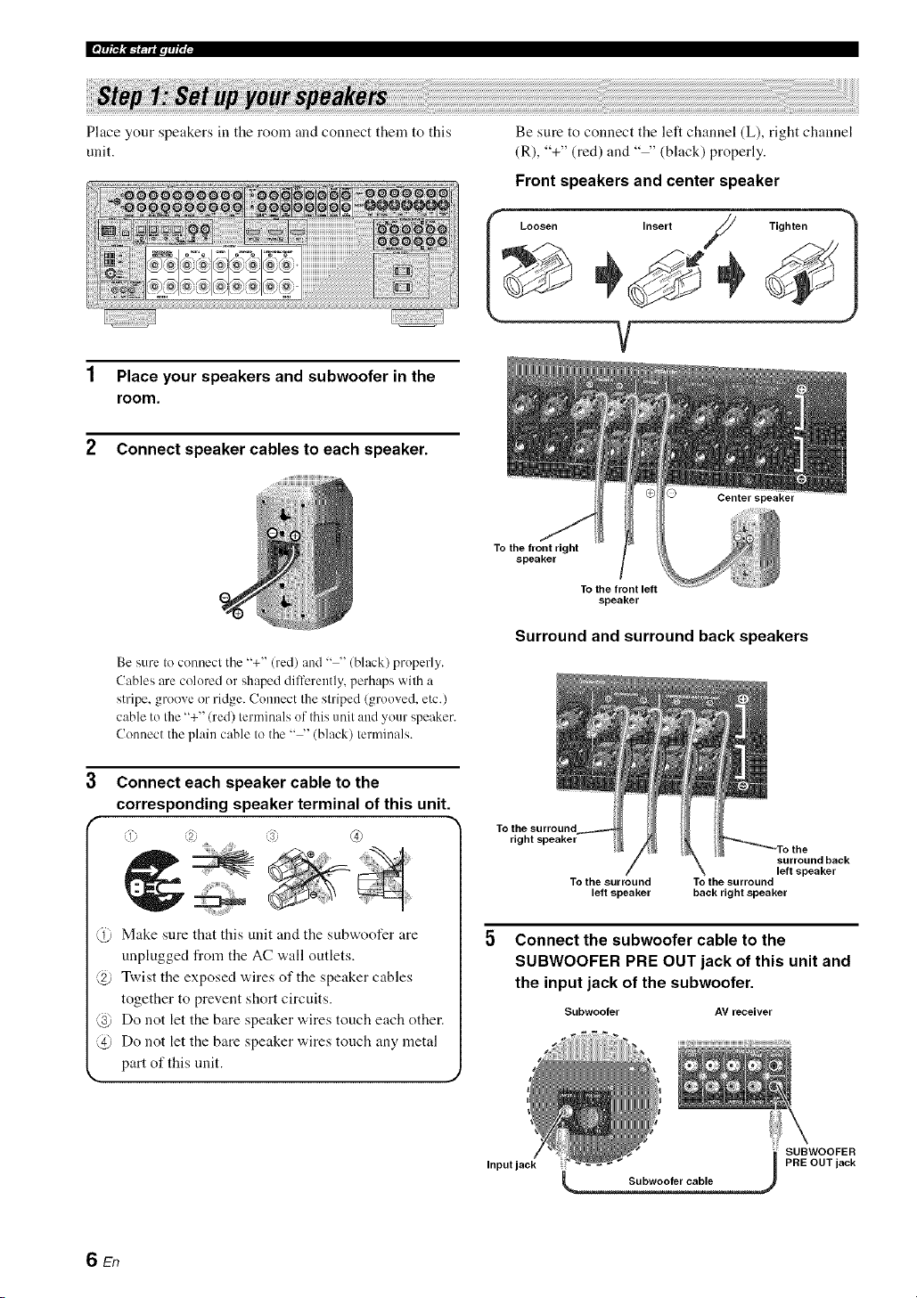
Ifp_t_,_-r. a.lqi'; i-
Place your speakers in the rooln and connect theln to this
unit.
1 Place your speakers and subwoofer in the
room.
2 Connect speaker cables to each speaker.
Be sure to connect the left channel (L), right channel
(R), "+" (red) and .... (black) properly.
Front speakers and center speaker
L..... ,nser;/ Tighten )
V
Be sure to connect the "+" (red) and .... (black) properly.
Cables are colored or shaped dilTerently, perhaps with a
stripe, groove or ridge. Connect the striped (grooved, etc.)
cable to the "+" (red) terminals of this unit and your speaker.
Connect the plain cable to the .... (black) terminals.
Connect each speaker cable to the
corresponding speaker terminal of this unit.
i 2. s; (4)
Make sure that this unit and the subwoofer are
unplugged from the AC wall outlets.
@ Twist the exposed wires of the speaker cables
together to prevent short circuits.
@ Do not let the bare speaker wires touch each other.
@ Do not let the bate speaker wires touch any metal
part of this unit.
To the front right
speaker
To the front left
speaker
Surround and surround back speakers
To the surround
right speaker
surround back
left speaker
To the surround To the surround
left speaker back right speaker
Connect the subwoofer cable to the
SUBWOOFER PRE OUT jack of this unit and
the input jack of the subwoofer.
Subwoofer AV receiver
SUBWOOFER
Input jack PRE OUT jack
6 En
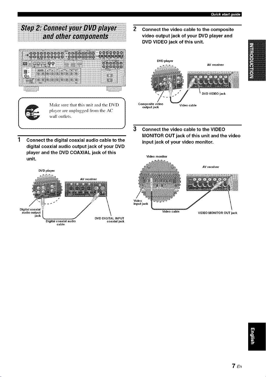
2 Connect the video cable to the composite
video output jack of your DVD player and
DVD VIDEO jack of this unit.
DVD player
AV receiver
_ Make sure that this unit and the DVD
player are unphigged from the AC
wall ontlets.
Connect the digital coaxial audio cable to the
digital coaxial audio output jack of your DVD
player and the DVD COAXIAL jack of this
unit.
DVD player
AV receiver
Composite video Video cable
output jack
jack
Connect the video cable to the VIDEO
MONITOR OUT jack of this unit and the video
input jack of your video monitor.
Video monitor
AV receiver
d_/
Digital coaxial
audio output
jack DVD DIGITAL INPUT
Digital coaxial audio coaxial jack
cable
Video
input jack
Video cable
VIDEO MONITOR OUT jack
7En

Ifp_,_-r.a.l.fi'; i-
4 Connect the supplied AM loop antenna and
indoor FM antenna to this unit.
See page 24 for tile connection information.
_M loop antenna
Indoor FM antenna
I Open the lever _ '(;rt Close the lever 1
The wire of the AM loop aotenna does not have any polarity and
you can connect either end of the wire to AM or GND terminal
Assembling the supplied AM loop antenna
5 Connect the power plug of this unit and other
components into the AC wall outlet.
This unit is equipped with AC OUTLET(S) for the power supply
of the other components (except Korea model). See page 24 for
details.
• For further connections
• Using the other kind of speaker
combinations
_ P. 12
• Connecting a video monitor via various
ways of the connection
_ P. 18
• Connecting a DVD player via various ways
of the connection
_ P. 19
• Connecting a DVD recorder or a digital
video recorder
_ P. 20
• Connecting a set-top box
_-_ P. 20
• Connecting a CD player, an MD recorder or
a turntable
_._ P. 21
• Connecting an external amplifier
_ P. 22
• Connecting a DVD player via analog multi-
channel audio connection
_ P. 22
• Connecting a Yamaha iPod universal dock
_ P. 23
• Using the REMOTE IN/OUT jacks
_ P. 23
• Using the VIDEO AUX jacks on the front
panel
_ P. 23
• Connecting an outdoor FM/AM antenna
_ P. 24
• Connecting the XM Mini-Tuner Dock
_ P. 53
The type of the power plug is difli:rent depending on the models.
SEn

Check the type of the connected speakers.
If the speakers are 6 ohm speakers, set "SP IMR" to
"6_QMIN" before using this unit (see page 25). 4 ohm
speakers can be also used as the front speakers (see
page 93).
1 Turn on the video monitor connected to this
unit.
2 Press @MASTER ON/OFF inward to the ON
position on the front panel.
'7'/R_!c_f.pf_q
Start playback of the desired DVD on your
player.
If the connected DVD pla_er is a Yanmha product and has
capability of the SCENE control signals with the REMOTE
OUT j,ck of this unit (see page 23), this unit can
automatically activate the DVD player and start playback
when you press the @SCENE1 button. Refer to the
instruction manual of the DVD player for flmher
inlornmtion.
5 Rotate @VOLUME to adjust the volume.
3
Press @SCENE1 button.
"DVD Viewing" appears in the front panel display,
and this unit automatically optimize own status for
the DVD playback.
The indicator on the selected SCENE button lights up while
this unit is in the SCENE mode.
When you change the input source or sound field program.
the SCENE mode is deactivated, and the indicator on the
selected SCENE button turns ofl.
• Using the other SCENE buttons
In the following cases, try pressing the corresponding
SCENE button to enjoy the playback of the desired
sources.
Case A: "I want to listen to a nmsic disc from the
connected DVD player as the background
music for this room..."
Press @SCENE2 (or
@SCENE2) to select "Disc
Listening".
Case B: "I want to watch a TV program..."
Press @SCENE3 (or
@SCENE3) to select "TV
Viewing".
Case C: "I want to listen to a music program of the
FM/AM radio station..."
Press @SCENE4 (or
@SCENE4) to select "Radio
Listening".
9En

Ifp_,_mla.l,fi'; i-
• To use the "TV Viewing" template (Case B), you must connecl
a salellile receiver, a cable TV receiver or an HDTV decoder Io
this unit in advance. See page 20for details.
• To use the "Radio Listening" template (Case C), you haxe to
tune into the desired radio station. See pages 5(1to 52 for the
tuning information.
• To achieve the best possible reception, orient the connected AM
loop antenna, or atljust the position of the end of the indoor FM
antenna.
--'4_'--
If you cannot findthe desired situation, you can select and change
the assigned SCENE template for the SCENE buttons. See
page 33 for details.
• After using this unit...
Press _)MAIN ZONE ON/OFF to set this unit to
the standby mode.
• Customizing the SCENE templates
• Using various SCENE templates
r_ p. 33
• Creating your original SCENE templates
r,_ p. 36
• Using various input sources
• Basiccontrols of this unit
r_ p. 37
• Enjoying FM/AM radio programs
_ P. 50
• Enjoying XM Satellite Radio programs
_ P. 53
• Using your iPod with this unit.
_ P. 58
This unit is set to the standby mode and consumes a small
amount of power in order to receive infrared signals from
the remote control. To turn on this unit from the standby
mode, press the desired @SCENE buttons (or
(_SCENE) or @MAIN ZONE ON/OFF on the front
panel (or @POWER on the remote control). See page 25
for details.
• Using various sound features
• Using various sound field programs
_ P. 42
• Using the pure direct mode for high fidelity
sound
_-_ P. 48
• Customizing the sound field programs
_> P. 61
• Adjusting the parameters of this unit
• Automatically optimizing the speaker
parameters for your listening room
(AUTO SETUP)
_ P. 28
• Manually adjusting various parameters of
this unit manually
_,_ P. 71
• Setting the remote control
_._ P. 84
• Adjusting the advanced parameters
r.> p. 92
• Additional features
Automatically turning off this unit
_> P. 41
10 En

_iack
(U.S.A. and Canada
models only)
Connect the XM Miui-
Ttmer Dock (sold
separalely).
R 53
DOCK terminal
('onuect a Yamaha iPod
universal dock
(sold separately).
R 23
CH INPUT jacks
Counecl the input source
cmnponeul equipped with the
multi-channel output .jacks.
P. 22
(Video jacks '7
Couuect the video cable
plugs. . -.
o@@@@@
°'°%@@@@@@@@@@
Dw ou, " wR ou,
%
jacks
Connect the digital audio
cable plugs.
P. 19-21
Connecl the speakers.
® ® ®°°@® ®i
I I
I
VOLTAGE SELECTOR
(Asia and General models
only)
R 4
AC OUTLET(S)
R 24
Connect the FM and AM
auleuua.
P. 24
REMOTE IN/OUT jacks
Couuect Ihe reulote con/rul
input and output jacks of the
Va/i/aha compoueuls.
P. 23
11 En
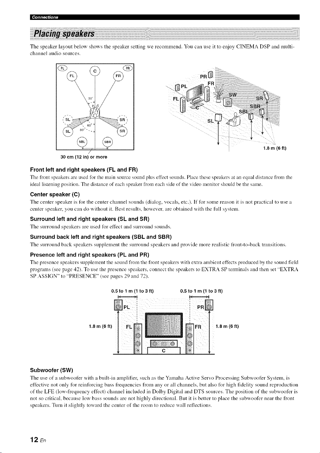
The speaker layout below shows the speaker setting we recomnlend. You can use it to enjoy CINEMA DSP and multi-
channel audio sources.
QD
/
30 cm (12 in) or more
_F
FL
1.8 m (6 ft)
Front left and right speakers (FL and FR)
The front speakers are used for the main source sotmd plus effect sonnds. Place these speakers at an equal distance from the
ideal listening position. The distance of each speaker from each side of the video monitor should be the same.
Center speaker (C)
The center speaker is for the center channel sounds (dialog, vocals, etc.). If for some reason it is not practical to use a
center speaker, you can do without it. Best results, however, are obtained with the full system.
Surround left and right speakers (Sk and SR)
The surround speakers are used I\_r effect and surround sounds.
Surround back left and right speakers (SBL and SBR)
The surround back speakers supplement the surround speakers and provide more realistic flout-to-back transitions.
Presence left and right speakers (PL and PR)
The presence speakers supplement the sound from the front speakers with extra ambient effects produced by the sound field
programs (see page 42). To use the presence speakers, connect the speakers to EXTRA SP terminals and then set "EXTRA
SP ASSIGN" to "PRESENCE" (see pages 29 and 72).
1.8 m (6 ft)
0.5 to 1 m (1 to3 ft) 0.5 to 1 m (1 to 3 ft)
I I
1.8 m (6 ft)
Subwoofer (SW)
The use of a snbw, oofer w,ith a built-in amplifier, such as the Yamaha Active Servo Processing Subwoofer System, is
effective not only for reinforcing bass frequencies from any or all channels, but also for high fidelity sound reproduction
of the LFE (low-frequency effect) channel included in Dolby Digital and DTS sources. The position of the subwoofer is
not so critical, because low bass sounds are not highly directional. But it is better to place the subwoofer near the front
speakers. Turn it slightly toward the center of the room to reduce wall reflections.
12 En

Be sure to connect the left channel (L), right channel (R), "+" (red) and "-" (black) properly. If the connections are faulty,
this unit cannot reproduce the input sources accurately.
Caution
• Before connecting the speakers, make sure that this unit is turned off (see page 25).
• Do not let the bare speaker wires touch each other or let them touch any metal part of this unit. This coukt damage
this unit and/or the speakers. If the speaker wires are short-circuited, "CHECK SP WIRES" appears in the front
panel display when you turn on this unit.
• Use the magnetically shielded speakers. If this type of speaker still creates interference with the monitor, place the
speakers away from the monitor.
• If you are to use 6 ohm speakers, be sure to set "SP IMR" to "6f2 MIN" before using this unit (see page 25). 4 ohm
speakers can be also used as the front speakers (see page 93).
A speaker cord is actually a pair of insulated cables running side by side. Cables are colored or shaped dilt'erently, perhaps with a stripe,
groove or ridge. Connect the striped (grooved, etc.) cable to the "+" (red) terminals of this unit and your speaker. Connect the plain cable
to the .... (black) terminals.
EXTRA SP terminals
Connect the alternative li'ont speaker system (FRONT B), presence speakers or Zone 2 speakers.
To select the function of the speakers commcted to the EXTRA SP terminals, set the "EXTRA SP
ASSIGN" parameter in "SOUND MENU" (see page 72).
You can also select the function of the speakers connected to the EXTRA SP terminals in "AUTO
SETUP" (see page 29).
Subwoofer
Right Left
Front speakers
(FRONT A)
Right Left
Surround speakers
Center speaker
Right Left
Surround back speakers
When you use single surround back speaker, connect
the speaker to the lefl SURROUND BACKterminal
(SINGLE).
13 En
|'=.Jffft_vJf_
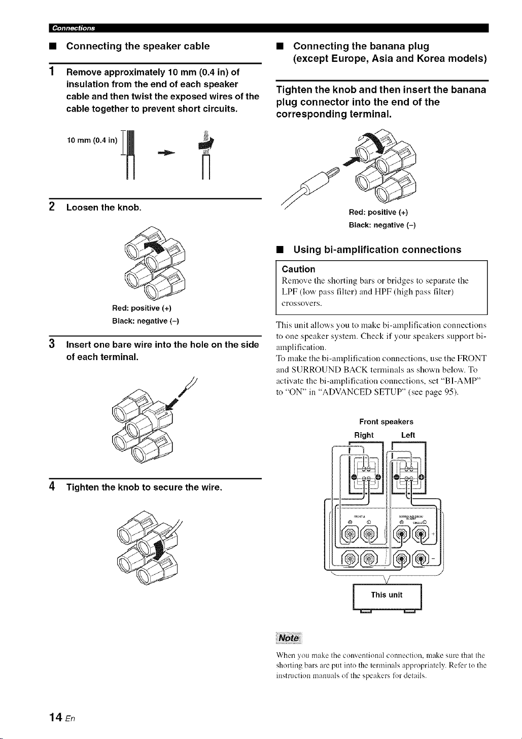
• Connecting the speaker cable
Remove approximately 10 mm (0.4 in) of
insulation from the end of each speaker
cable and then twist the exposed wires of the
cable together to prevent short circuits.
2 Loosen the knob.
Red: positive (+)
Black: negative (-)
Insert one bare wire into the hole on the side
of each terminal.
4 Tighten the knob to secure the wire.
• Connecting the banana plug
(except Europe, Asia and Korea models)
Tighten the knob and then insert the banana
plug connector into the end of the
corresponding terminal.
Bed: positive (+)
Black: negative (-)
• Using bi-amplification connections
Caution
Remove the shorting bars or bridges to separate the
LPF (low pass filter) and HPF (high pass filter)
crossovers.
This unit allows you to make bi-amplification connections
to one speaker system. Check if your speakers support bi-
amplification.
To make the bi-amplification connections, use the FRONT
and SURROUND BACK terminals as shown below. To
activate the bi-amplification connections, set "BI-AMP"
to "ON" in "ADVANCED SETUP" (see page 95).
Front speakers
Right Left
--V oo3
@ © @ _I._LE@
®&-
x/
When you make the conventional connection, make sure that the
shorting bars are put into the lerminals appropriately. Refer Io Ihe
instruction mammls of the speakers lot details.
14 En

.qlflI_f|qP
Audio jacks and cable plugs Video jacks and cable plugs
DIGITALAUDIO
© @
©©
/White/ /Red/
t t
Left and right
analog audio
cable plugs
DIGITAL
COAXIAL
©
/Orange)
t
Coaxial
digital audio
cable plug
OPTICAL
t
Optical
digital
audio cable
plug
COMPONENT VIDEO
VIDEO S VIDEO Y PB PR
© @oo©
(Yellow) (Green) /Blue) /Red)
t t t t t
Composite S-video Component
video cable cable plug video cable
plug plugs
• Audio jacks
This unit has three types of audio jacks. Connection
depends on the availability of audio ,jacks on your other
components.
AUDIO jacks
For couventional aualog andio signals tral:lsmitted via left
and right analog audio cables. Connect red plugs to the
right .jacks and white plugs to the left jacks.
DIGITAL COAXIAL jacks
For digital audio signals transmitted via coaxial digital
audio cables.
DIGITAL OPTICAL jacks
For digital audio signals trausmitted via optical digital
audio cables.
• You can use the digital jacks to input PCM, Dolby Digital and
DTS bitstreams. When you connect components to both the
COAXIAL and OPTICAL jacks, priority is given to the signals
input at the COAXIAL jack. All digital input jacks are
compatible with digital signals with up to 96 kHz of sampling
frequency.
• Pull out the cap fi'om the optical .jack before you connect the
fiber optic cable. Do not discard the cap. When you are not
using the optical .jack, be sure to put the cap back in place. This
cap protects the .jack from dust.
• Video jacks
This unit has three types of video jacks. Connection
depends on the availability of input .jacks on your video
monitor.
VIDEO jacks
For conventional composite video signals transmitted via
composite video cables.
S VIDEO jacks
For S-video signals, separated into the luminance (Y) and
chrominance (C) video signals transmitted on separate
wires of S-video cables.
COMPONENT VIDEO jacks
For component video signals, separated into the
luminance (Y) and chrominance (Pro PIO video signals
transmitted on separate wires of component video cables.
This unit is equipped with the video conversion fimction. See
pages 17 and 81 for details.
15 En

[[¶qlfli_'_ffql_
• HDMI compatibility with this unit
Audio signal Audio signal Compatible
HDMI
types formats
components
2oh Linear PCM 2ch. 32-192 kHz. CD. DVD-Video.
16/20/24 bit DVD-Audio. etc.
Multbch Linear 8ch. 32-192 kHz. DVD-Audio. etc.
PCM 16/20/24 bit
DSD 2/5. lch. 2.8224 SAC[). etc.
MHz. 1 bit
Bitstream Dolby Digitah DTS DVD-Video. etc.
This unit's HDMI interface is based on the t_llowing
standards:
• HDMI Version 1.2a (High-Definition Multimedia
Interface Specification Version 1.2a) licensed by
HDMI Licensing, LLC.
• HDCP Revision 1.1 (High-bandwidth Digital
Content Protecfion System Revision 1.1) licensed
by Digital Content Protecfion, LLC.
• When CPPM copy-protected DVD audio is played back. video
and audio signals may not be output depending on the type of
the DVD player.
• This unit is not compatible with HDCP-incompatible HDMI or
DVI components.
• You can check the potential problem about the HDMI
connection (see p_ge 41 ).
• HDMI jack and cable plug
HDMI cable plug
• We recommend using an HDMI cable shorter than 5 meters (16
feet) with the HDMI logo printed on it.
• Use a conversion cable (HDMI jack <_- DVI-D jack) to connect
this unit to other DVI components.
Notes
• Do not disconnect or connect the cable or turn off the power of
the HDMI components connected to the HDMI OUT jack of
this unit while data is being transferred. Doing so may disrupt
playback or cause noise.
• Audio signals input at input jacks other than the HDMI IN 1 or
HDMI IN 2 jack of this unit cannot be digitally output at the
HDMI OUT jack.
• If you turn off the power of the video monitor connected to the
HDMI OUT jack via a DVI connection, this unit may lail to
establish the connection to the component.
16 En
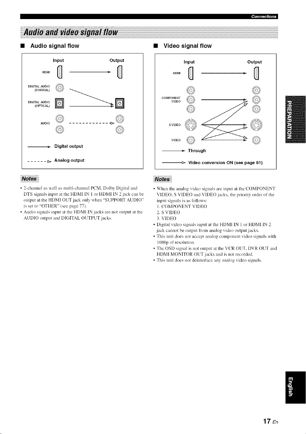
.qlfl|_f|qlb
Audio signal flow
Input
HDMI
DIGITAL AUDIO
(COAXIAL)
DIGITAL AUDIO
(OPTICAL)
©
Output
AUDIO
--._- Digital output
...... _. Analog output
Note
• 2-channel as well as molti-chaonel PCM. Dolby Digital and
DTS signals inpot at the HDMI IN 1 or HDMI IN 2jack can be
output at the HDMI OUT jack only when "S1JPPORT AUDIO"
is set to "OTHER" (see page 77).
• Audio signals input at the HDMI IN .jacks are not output at the
AUDIO output and DIGITAL OUTPUT jacks.
• Video signal flow
Input
HDMI
Output
cooPo,ya o'© ©
SVIDEO
© ©
-_ Through
--=_'- Video conversion ON (see page 81)
• When the analog video signals are input at the COMPONENT
VIDE(). S VIDEO and VIDEO jacks, the priGrity Grder of the
input signals is as follows:
1. COMPONENT VIDEO
2. S VIDEO
3. VIDEO
• Digital video signals input at the HDMI IN 1 or HDMI IN 2
jack cannot be output from anah)g video output jacks.
• This unit clods not accept anah)g component videG signals with
1080p of resolution.
• The OSD signal is nGt output at the VCR OUT. DVR OUT and
HDMI MONITOR OUT jacks and is not recorded.
• This unit dGes not deinterlace any analog video signals.
17En
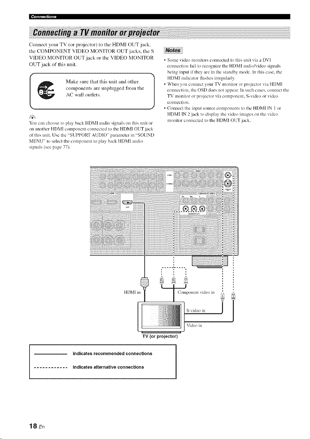
Connect your TV (or proiector) to the HDMI OUT jack,
the COMPONENT VIDEO MONITOR OUT jacks, the S
VIDEO MONITOR OUT jack or the VIDEO MONITOR
OUT jack of this unit.
Make sure that this unit and other
components are unplugged from the
AC wall outlets.
You can choose to play back HDMI audio signals on this unit or
on another HDMI component connected to the HDMI OUT.jack
of this unit. Use the "SUPPORT AUDIO" parameter in "SOUND
MENU" to select the component to play back HDMI audio
signals (see page 77).
• Some video monitors connected to this unit via a DVI
connection lhil to recognize the HDMI audio/video signals
being input if they are in the standby mode. In this case. the
HDMI indicalor flashes irregularly.
• When you colmect your TV monilor or projector via HDMI
conneclion, the OSD does not appear. In such cases, connect the
TV monitor or projector via component. S-video or video
conneclion.
• Connecl the input source components to the HDMI IN 1 or
HDMI IN 2 j:Jck to disphq the video im:_,qeson the video
monitor connected to the HDMI OUT j:Jck.
HDMI in
J;;k T
S-video in i /
Video in
TV (or projector)
indicates recommended connections
indicates alternative connections
18 En

I _ Make sure that this unit and other l
J
components are unplugged from the
AC wall outlets.
Notes
• When "VIDE() CONV." is set to "OFF" (see page NIL be sure
to make the same type of video connections as those made for
your TV (see page 18). For example, if you connected your TV
to the VIDEO MONITOR OUT jack of this unit. connect your
other components to the VIDEO jacks.
• When "VIDEO CONV." is set to "ON" (see page 81), the
converted video signals are output only at the MONITOR OUT
.jacks. To record a source, make the same type of video
com_ections between each component.
• To make a digital connection to a component other than the
delimit component assigned to each DIGITAL INPUT or
DIGITAL OUTPUT jack, select the corresponding setting for
"OPTICAL OUT". "OPTICAL IN". or "COAXIAL IN" in "110
ASSIGNMENT" (see page 78).
• If you connect your DVD player to both the DIGITAL INPUT
(OPTICAL) and the DIGITAL INPUT (COAXIAL)jacks.
priority is given to the signals input at the DIGITAL INPUT
(COAXIAL) jack.
• Connecting a DVD player
!
DVD player
Op!ical ?ul VMeo oul
I HDMI O/l[[ I Componenl vMeo
I 1
indicates recommended connections
indicates alternative connections
19 En

• Connecting a DVD recorder, PVR or VCR
Audio oul
__ Audi_, ill
DVD recorder, PVR or VCR
Video out S-video out
S-video in
Video in
Audio oul
k_
DVD recorder, PVR
• Connecting a set-top box
Satellite receiver, cable TV
receiver or HDTV decoder
|
.L I 1-- Com_,oo_n_,'_d_.oou*|
/
20 En

• Connecting audio components
No es;
• To make a digital c(mnection to a component other than the delhult component assigned to each the DIGITAL INPUT jack or the
DIGITAL OUTPUT jack. select the corresponding setting fl)r "OPTICAL OUT". "OPTICAL IN". or "COAXIAL IN" in "I/O
ASSIGNMENT" (see page 78).
• Connect your turntable to the GND terminal of this unit to reduce noise in the signah However, you m:_yhear less noise without the
connection to the GND terminal fl)r some turntables.
• The PHONO jacks are only compatible with a turntable with an MM or a high-output MC cartridge. To connect a turntable with a low-
output MC cartridge to the PHONO jacks, use an in-line boosting transformer or an MC-head amplifier.
• When you connect both the DIGITAL INPUT (OPTICAL)jack and the DIGITAL INPUT (COAXIAL)jack to an audio component.
the priority is given to the DIGITAL INPUT (COAXIAL)jack.
Turntable CD player
CD recorder, MD
recorder ortape deck
indicates recommended connections
indicates alternative connections
21 En
[[¶'tfff|_f|'tfF
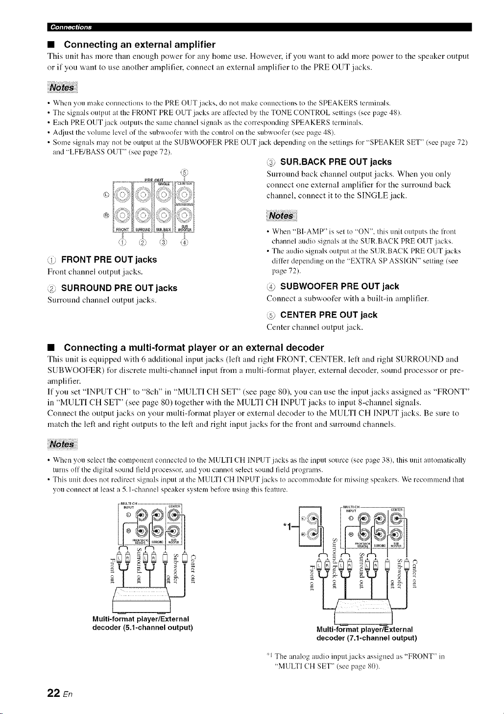
• Connecting an external amplifier
This unit has more than enongh power for any home use. Ho'a, ever, if you want to add more power to the speaker output
or if you want to use another amplifier, connect an external amplifier to the PRE OUT jacks.
• When you make connections to the PRE OUT jacks, do not make connections to the SPEAKERS terminals.
• The signals output at the FRONT PRE OUT jacks are afli:cted by the TONE CONTROL settings (see page 48).
• Each PRE OUT jack outputs the same channel signals as the corresponding SPEAKERS terminals.
• A(ljust the vohnne level of the subwooli:r with the control on the subwoofcr (see page 48).
• Some signals may not be output at the SUBWOOFER PRE OUT jack depending on the settings for "SPEAKER SET" (see page 72)
and "LFE/BASS OUT" (see page 72).
@ SUR.BACK PRE OUT jacks
Surround back channel output jacks. When you only
connect one external amplifier for the surround back
channel, connect it to the SINGLE jack.
©
®
@ FRONT PRE OUT jacks
Front channel output jacks.
@ SURROUND PRE OUT jacks
Surround channel output jacks.
• When "BI-AMP" is set to "ON', this unit outputs the front
channel audio signals at the SUR.BACK PRE OUT jacks.
• The audio signals output at the SUR.BACK PRE OUT jacks
differ depending on the "EXTRA SP ASSIGN" setting (see
page 72).
@ SUBWOOFER PRE OUT jack
Connect a subwoofer with a built-in amplifier.
@ CENTER PRE OUT jack
Center channel output jack.
• Connecting a multi-format player or an external decoder
This unit is equipped with 6 additional input jacks (left and right FRONT, CENTER, left and right SURROUND and
SUBWOOFER) for discrete multi-channel input from a nmlti-format player, external decoder, sound processor or pre-
amplifier.
If you set "INPUT CH" to "8ch" in "MULTI CH SET" (see page 80), you can use the input jacks assigned as "FRONT"
in "MULTI CH SET" (see page 80) together with the MULTI CH INPUT jacks to input 8-channel signals.
Connect the output jacks on your mnlti-format player or external decoder to the MULTI CH INPUT jacks. Be sure to
match the left and right outputs to the left and right input jacks for the front and surround channels.
Notes
• When you select the component connected to the MULTI CH INPUT jacks as the input source (see page 38), this unit automatically
turns off the digital sound field processor, and you cannot select sound field pr()grams.
• This unit does not redirect signals input at the MULTI CH INPUT jacks to accommodate for missing speakers. We recommend that
you connect at least a 5. I-channel speaker system before using this feature.
Multi-format player/External
decoder (5.1-channel output)
Multi-format player/External
decoder (7.1-channel output)
'1 The analog audio input jacks assigned as "FRONT" in
"MULTI CH SET" (see page 80).
22 sn
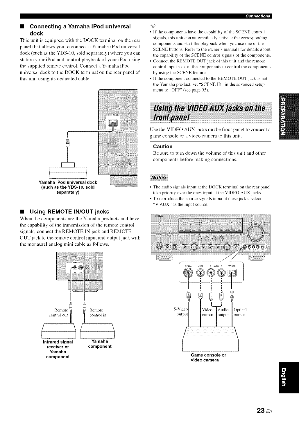
• Connecting a Yamaha iPod universal
dock
This unit is equipped with tile DOCK tertninal on tile rear
panel that allows you to connect a Yamaha iPod universal
dock (such as the YDS-10, sold separately) where you can
station your iPod and control playback of your iPod using
the supplied remote control. Connect a Yamaha iPod
universal dock to the DOCK terminal on the rear panel of
this unit using its dedicated cable.
• Using REMOTE IN/OUT jacks
When the components are the Yamaha products and have
the capability of the transmission of the remote control
signals, connect the REMOTE IN jack and REMOTE
OUT jack to the remote control input and output jack with
the monaural analog mini cable as follows.
,qffl|_If|'tP
• If the components hme the capahility of the SCENE control
signals, this unit can autonmtically activate the corresponding
components and start the playback when you use one of the
SCENE buttons. Reler to the owner's manuals lot details about
the capability of the SCENE control signals of the components.
• Connect the REMOTE OUT jack of this unit and the remote
control input jack of the components to control the components
by using the SCENE feature.
• If the component connected to the REMOTE OUT jack is not
the Yamaha product, set "SCENE IR" in the advanced setup
menu to "OFF" (see page 95).
Use the VIDEO AUX jacks on the front panel to connect a
game console or a video camera to this unit.
Caution
Be sure to turn down the volume of this unit and other
components before making connections.
• The audio signals input at the DOCK terminal on the rear panel
take priority over the ones input at the VIDEO AUX jacks.
• To reproduce the source signals input at these.jacks, select
"V-A13X" as the input source.
Relnole
c°nR':_;t_;:_[ I control in
(
Infrared signal Yamaha
receiver or component
Yamaha
component
S-Vide,
outpul
Optical
output
Game console or
video camera
23 En

[[¶qcfli_'_f|ql_
Both FM and AM indoor antennas are supplied with this
unit. Connect each antenna correctly to the designated
terminals. In general, these antennas should provide
sufficient signal strength.
_%,.
See page 8 for connection information of the supplied indoor FM
antenna and AM loop antenna.
• The AM loop antenna should be placed away from this unit.
• The AM loop antenna should always be connected, even if an
outdoor AM antenna is connected to this unit.
• A properly installed outdoor antenna provides clearer reception
than an indoor one. If you experience poor reception quality,
install an outdoor antenna. Consult the nearest authorized
Yamaha dealer or service center about outdoor antennas.
AM loop
antenna
(supplied)
Indoor FM
extended ouldoors hOl/l a
Willdow.
Ground (GND terminal)
For maximum satcly und mininmm interlcrcnce, connect the
antenna GND terminal to a good earth ground. A good elu'lh
ground is a melal strike driven into moisl earlh.
(U.S.A. model)
To the AC wall outlet
• AC OUTLET(S) (SWITCHED)
U.K. and Australia models ..................................... l outlet
Korea model ............................................................... None
Other models ......................................................... 2 outlets
Use these outlet(s) to supply power to any connected
components. Connect the power cable of your other
components to these outlet(s). Power to these ontlet(s) is
supplied when the main zone or Zone 2 is tnrned on.
However, power to these outlet(s) is cut off when the main
zone and Zone 2 are turned off or when (@MASTtZR ON/
OFF on the front panel is pressed and released outward to
the OFF position. For information on the maxinmm power
or the total power consumption of the components that can
be connected to these outlet(s), see "Specifications" on
page 108.
Memory back-up
The memory back-np circuit prevents the stored data
from being lost even if this unit is in the standby mode.
However. the stored data will be lost in case the power
cable is disconnected from the AC wall outlet or if the
power supply is cut off t_r more than one week.
24 En

.qlfli_'af|°/l_
Caution
If you are to use 6 ohm speakers, set "SP IMR" to
"60-- MIN" as follov,,s BEFORE using this unit. 4 ohm
speakers can be also used as the front speakers.
1 Make sure this unit is turned off,
Refer to the right cohmm for details.
2
3
Press and hold @TONE CONTROL on the
front panel and then press @MASTER ON/
OFF inward to the ON position to turn on this
unit.
This unit turns on, and the advanced setup menu
appears in the front panel display.
Rotate the @PROGRAM selector on the
front panel to select "SP IMP,".
"SP IMP." and the current speaker impedance setting
("8f2 MIN") appear in the front panel display.
4 Press @TONE CONTROL on the front
panel repeatedly to select "60- MIN".
5 Press @MASTER ON/OFF on the front
panel to release it outward to the OFF
position to save the new setting and turn off
this unit.
The selting you made is reflecled next lime you turn on this
unil.
• Turning on this unit
Press @MASTER ON/OFF on the front panel
inward to the ON position to turn on this
unit,
When you turns on this unit by pressing @MASTER
ON/OFF, the main zone is turned on.
When you mrn on Ilaisunit. there will be a 4 I(15_second delay
belore this unit can reproduce sound.
• Turning off this unit
Press @MASTER ON/OFF on the front panel
again to release it outward to the OFF
position to turn off this unit,
• @MAIN ZONE ON/OFF on the front panel as well as
@POWER and (_)STANDBY oi/the remote control are
operational only when @MASTER ON/OFF is pressed
inward to the ON position.
• As usual, we recommend using the standby mode to turn off this
unit.
• Set the main zone to the standby mode
Press @MAIN ZONE ON/OFF
(or @STANDBY) to set the main zone to the
standby mode.
In the standby mode, this unit consumes a small amount of
power in order to receive infrared signals from the remote
control.
• Turning on the main zone from the
standby mode
Press @MAIN ZONE ON/OFF (or @POWER)
to turn on the main zone.
• You can also turn (1I/the main zone by pressing (_SCENE (or
@SCENE) buttons.
• When you turn on this unit. there will be a 4 to 5_second delay
before this unit can reproduce sound.
• These buttons are operational only when (_ MASTER ON/
OFF is pressed inward to the ON position.
gl
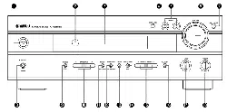
25 En
[[¶'tfffi_f|'tf_
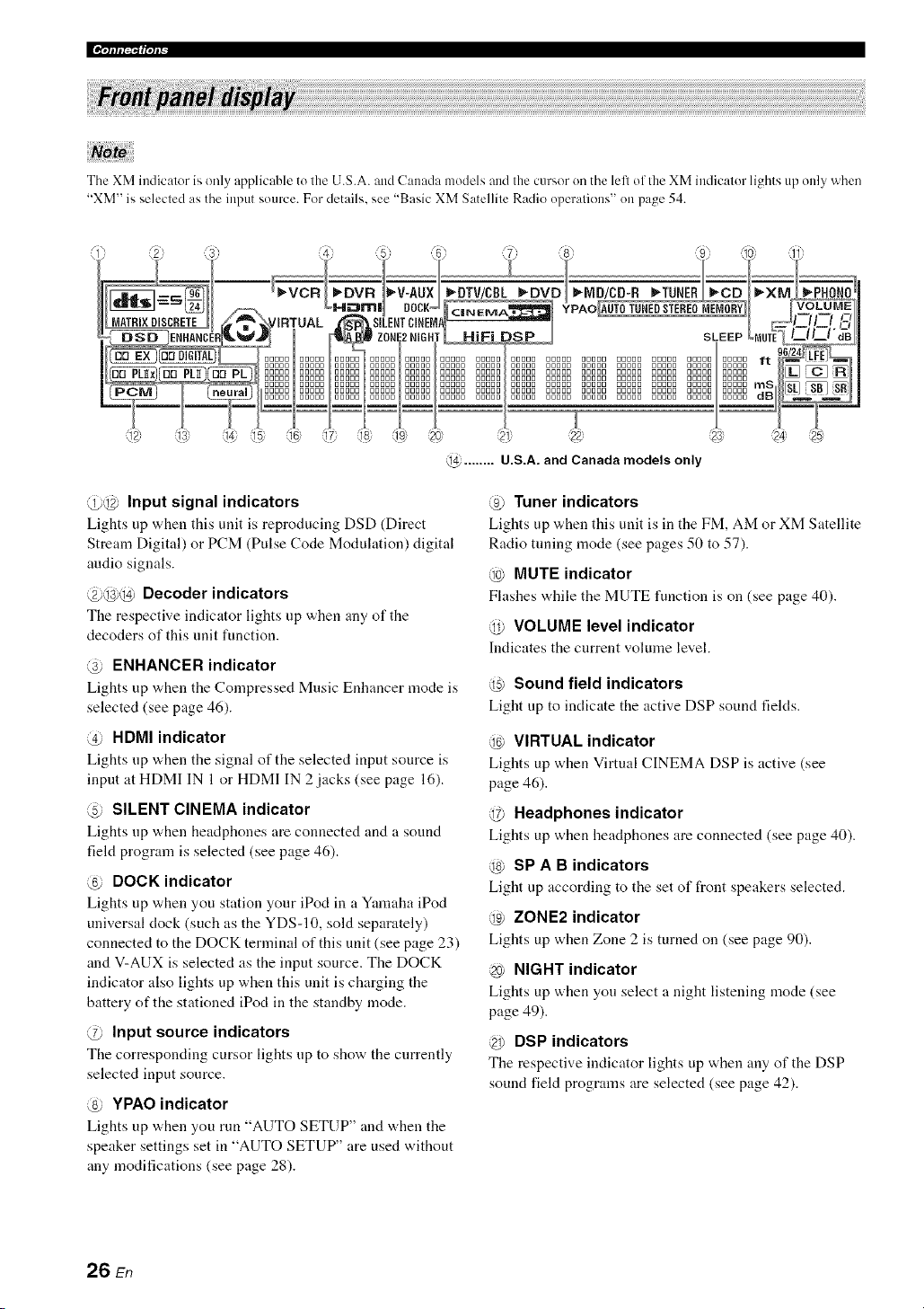
The XM indicator is only applicable to the U.S.A. and Canada models and the cursor on the left of the XM indicator lights up only when
"XM" is selected as the input source. For details, see "Basic XM Satellite Radio operations" on page 54.
@ ........ U.S.A. and Canada models only
@@ Input signal indicators
Lights up when this unit is reproducing DSD (Direct
Stream Digital) or PCM (Pulse Code Modulation) digital
audio signals.
@@@ Decoder indicators
The respective indicator lights up when any of the
decoders of this unit function.
@ ENHANCER indicator
Lights up when the Compressed Music Enhancer mode is
selected (see page 46).
@ HDMI indicator
Lights up v,,hen tile signal of the selected input source is
input at HDMI IN 1 or HDMI IN 2 jacks (see page 16).
@ SILENT CINEMA indicator
Lights up when headphones are connected aM a souM
field program is selected (see page 46).
@ DOCK indicator
Lights up when you station your iPod in a Yamaha iPod
universal clock (such as the YDS-10, sold separately)
connected to the DOCK terminal of this unit (see page 23)
and V-AUX is selected as the input source. The DOCK
indicator also lights up when this unit is charging the
battery of the stationed iPod in the standby mode.
@ Input source indicators
The corresponding cursor lights up to show the currently
selected input source.
@ YPAO indicator
Lights up v,,hen you run "AUTO SETUP" and "a,hen tile
speaker settings set in "AUTO SETUP" are used without
any modifications (see page 28).
@ Tuner indicators
Lights up when this unit is in tile FM, AM or XM Satellite
Radio tuning mode (see pages 50 to 57).
@ MUTE indicator
Flashes "a.hiletile MUTE functiou is on (see page 40).
@ VOLUME level indicator
Indicates tile current volmne leveh
@ Sound field indicators
Light up to indicate the active DSP sound fields.
@ VIRTUAL indicator
Lights up when Virtual CINEMA DSP is active (see
page 46).
@ Headphones indicator
Lights up when headphones are connected (see page 40).
@ SP A B indicators
Light up according to the set of front speakers selected.
@ ZONE2 indicator
Lights up when Zone 2 is turned on (see page 90).
@ NIGHT indicator
Lights up when you select a night listening mode (see
page 49).
@ DSP indicators
Tile respective indicator lights up when any of the DSP
sound field programs are selected (see page 42).
26 En

@ Multi-information display
Shows the name of the current sound field program and
other information when adjusting or changing settings.
@ SLEEP indicator
Lights up while the sleep timer is on (see page 41).
@ 96/24 indicator
Lights up when a DTS 9(,/24 signal is input to this unit.
@ Input channel and speaker indicators
LFE indicator
====_====::3 "=Presence speaker indicators
[_ [_ [_l lnput ch mnel indic,lors
_ _ Surr_ und back speaker indical( rs
LFE indicator
Lights up when the input signal contains the LFE
signal.
Input channel indicators
Indicate the channel components of tile current digital
input signal.
Presence and surround back speaker
indicators
Light up according to tile number of presence and
surround back speakers set for "EXTRA SP ASSIGN"
(see page 72) and "SB L/R SP" (see page 73) in
"SOUND MENU" when this unit is in the auto setup
(see page 28) or the speaker level setting in "SOUND
MENU" (see page 74) procedure.
-#:
• You can make settings for surround back speakers autonlatically
by running "AUTO SETUP" (see page 28) or manually by
a@lsting settings for "SB L/R SP" (see page 73) in "SOUND
MENU".
• To use the presence speakers, set "EXTRA SP ASSIGN" to
"PRESENCE" (see pages 29 or 72).
.qfllqlffql_-
The remote control transmits a directional infrared ray.
Be sure to aim the remote control directly at the remote
control sensor on this unit during operation.
Remote control sensor
Approximately 6 m (20 ft)
[. ]_=J
Infrared window (@)
Outputs infrared coutrol signals. Aim this window at tile
component you want to operate.
@TRANSMIT indicator
Flashes while tile remote control is sending infrared
signals.
Operation mode selector (@)
The function of some buttons depends oil tile operation
mode selector position.
AMP
Operates the amplifier function of this unit.
SOURCE
Operates tile component selected with an input
selector button (see page 86).
TV
Operates the TV assigned to either DTV/CBL or
PHONO (see page 85).
• Do not spill water or other liquids on the remote control
• Do not drop the remote control.
• Do not leave or store the remote control in the lbllowing types
of conditions:
places of high hunlidity, such as near a bath
places of high temperatures, such as near a heater or stove
places of extremely low temperatures
dusty places
• To set the remote control codes for other components, see
page 87.
27 En

This unit employs the YPAO (Yamaha Parametric Room Acoustic Optimizer) technology which lets you avoid
troublesome listening-based speaker setup and achieves highly accurate sound adjustments automatically. The supplied
optimizer microphone collects al_ld this unit analyzes the sound your speakers produce in your actual listening
euviroument.
2 Oonnectthesupp.edopt,mizermicrophone
i!! !=ii!!!!
to the OPTIMIZER MIC jack on the front
panel.
• Be advised that it is nornml lk)r h)ud test tones to be output
during the "AUTO SETUP" procedure.
• Tu achieve the best results, make sure the room is as quiet as
possible while the "AUTO SETUP" procedure is in progress. If
there is too much ambient noise, the results may not be
satishtctory.
"4¢--
• You can run "AUTO SETUP" using the system menu that
appears in the OSD or in the front panel display. This manual
uses the OSD illustratiuns tu explain the "AUTO SETUP"
procedure.
• Bekwe perfornfing operations, set the uperation mode selectur
on the remote control to (_)AMP.
• This unit uses the speakers counected to the FRONT A speaker
ternfinals as the front speakers lor the a@lstment.
Make sure of the following check points
before starting the AUTO SETUP operations.
Speakers are connected appropriately.
Headphones are disconnected from this unit.
This unit and the video monitor are turned on.
[71 The connected subwoofer is turned on and the
volume level is set to about halfway (or slightly
less).
[71 The crossover frequency controls of the
connected subwoofer is set to the maximum.
The room is sufficiently quiet.
Omni-directional
II _ microphone
The follovdng menu screen appears on the video
monitor.
gUTO: ItEIqU
+ EXTRI:I SP PSSiGlfl
ZOMI:-2 ?FFZUT E:
F'RFSEI4C:E MOIIE
SETLIp ....... I:IUTO
E g!....... 141:ITLIIRI:IL
STJ:flRT
[,,k]/["F] _LIpi[/c,_,!rl
[*I]/[> ] _Seiec't
Place the optimizer microphone at your
normal listening position on a flat level
surface with the omni-directional
microphone heading upward.
Optimizermicrophone
It is recomnmnded that you use a tripud (etc.) tu affix the
optimizer microphone at the same height as your ears would be
when you are seated in your listening position. Yuu can use the
attached screw of a tripod (etc.) to fix the optimizer microphone
to the tripod (etc.).
28 En

)117111111t'41almldal:lt._leI:_ll;(;lJ.'_:IQ_Ylel#llli_(;IJIlallllgelelli
4
Press @<:3 / L> to select the desired setting
for "EXTRA SP ASSIGN" and then press @V.
Extra speaker assignment
E::.:TH:;I:A:!!;?A:!!;:!;iSH
Selects the thnction of the speakers connected to the
EXTRA SP terminals.
Choices: FRONT B, ZONE2, PRESENCE, NONE
• When you use the alternative front speaker
system (see page 38)
Select "FRONT B".
• When you use the Zone 2 speakers (see
page 90)
Select "ZONE2" to set the function of the speakers
to the Zone 2 speakers. This unit drives the Zone 2
speakers by using the internal amplifier.
• When you use the presence speakers (see
page 12)
Select "PRESENCE" to set the function of the
speakers to the presence speakers.
• When you do not use the EXTRA SP
terminals
Select "NONE" to deactivate the EXTRA SP
terminals.
No!a::
If you select "ON" in "BI-AMP" (see page 95), you cannot
select "PRESENCE" or "ZONE2" in "EXTRA SP
ASSIGN".
Press @<1 / E> to select "SETUP".
Choices: AUTO, RELOAD, UNDO, DEFAULT
• Select "AUTO" to automatically run the entire
"AUTO SETUP" procedure.
• Select "RELOAD" to reload the last "AUTO
SETUP" settings and override the previous
settings.
• Select "UNDO" to undo the last "AUTO SETUP"
settings and restore the previous settings.
• Select "DEFAULT" to reset the "AUTO SETUP"
parameters to the initial factory settings.
Press @<:3/ _ to select the desired setting of
"EQ" and then press @V.
Parametric equalizer type i!!(;!
Parametric equalizer adjusts the level of the specified
frequency bands. This unit automatically selects the
crucial frequency bands for the listening room and
adjusts the level of the selected frequency bands to
create a cohesive sound fiekt in the room. You can
select the type of the parametric equalizer adjustment
from the following choices.
Choices: NATURAL, FLAT, FRONT
• Select "NATURAL" to average out the frequency
response of all speakers with higher frequencies
being less emphasized. Recommended if the FLAT
setting sounds a little harsh.
• Select "FLAT" to average the frequency response
of all speakers. Recommended if all of your
speakers are of similar quality.
• Select "FRONT" to adjust the frequency response
of each speaker in accordance with the sound of
your front speakers. Recommended if your front
speakers are of much higher quality than your other
speakers.
Press (_V to select "START" and then press
@IENTIER to start the setup procedure.
This unit starts the auto setup procedure. Loud test
tones are output from each speaker during the auto
setup procedure. Once all items are set, the
"AUTO:RESULT" display appears in the OSD.
• During the auto setup procedure, do not perform any
operation on this unit.
• We recommend getting out of the room while this unit is in
the auto setup procedure. It takes approximately 3 mimltes
lk_rthis unit to complete the auto setup procedure.
• "RELOAD" or "UNDO" is axailable only when you have
previously run "AUTO SETUP" and confirmed the results.
• "RELOAD" or "UNDO" is not available when you change
the setting of "BI-AMP" in the advanced setup (see
page 95) or "EXTRA SP ASSIGN" in "SOUND MENU"
(see page 72).
29 En

olFil, t _ u rolia.-_ .i_ m_t-_ _.ao .11_ii,1ol riml_li;llllao ||Olql r
This unit performs the following checks:
Speaker wiring i,iiRiN(!!i
Checks "a.hich speakers are connected and the
polarity of each speaker.
Speaker size SiZE
Checks the frequency response of each speaker mid
sets the appropriate low-frequency crossover for each
channel.
Speaker distance [:,i STI::iNCE
Checks the distance of each speaker from the
listening position and adjusts the timing of each
channel.
Equalizing m,_ h',_ r'::=r_h':::
Checks and adjusts the tonal characteristics of all the
speakers by the setting of"EQ".
Speaker level LEUEL
Checks and adjusts the volume level of each speaker.
The display changes as follows.
I_LITCI_HENLI
EXTF:P SF' PSSiGM
ZOHF2 )FROIIT E:
F'RESEHCE HOHE
SETLIP....... PLITO
Eg!....... 14PTUIRJqL
÷ STPRT
L,k] '["_] ::UF @o_,:n
["4_ '["_'] ; Se i ,>:;[.
€
glLITCI_C:HI_C:K
II'4IT il41_ IZ iIflG
÷ UIRII4G
SIZE 'DiSTgIIIC:E
Eg!UglL IZ IHG
LEHEL
C:HECI: C:H=C:EilTEIR
illii ........
[.,k] : E::_:i [.
I:ILITCI_RI_SLILT
÷ RESULT
SF' : 3,4/0,, I
DIST: 14, O, 17d_,ft
LUL ; -9,0"_6,,5,:._EI
)SET C:I:II_C:EL
[±]/[_] _ LIFiDo_,!r_
[EHTER ]_ Errter
The results displayed under "RESULT" are as
follows.
Number of speakers SP
Displays the number of speakers connected to this
unit in the following order:
Fmnt/Back/Subwoofer
Speaker distance i):i:S"F
Displays the speaker distance from the listening
position in the following order:
Closest speaker distance/Farthest speaker distance
Speaker level Li.,il....
Displays the speaker output level in the follov,'ing
order:
Lowest speaker output level/Highest speaker output
level
• If "E-10:INTERNAL ERROR" appears during the testing
procedure, restart from step 4.
• If you selected "RELOAD" ill step 4. no test tones are
output.
• If an error occurs during the "AUTO:CHECK" procedure.
the setup procedure is canceled and all error screen
appears. For details, see "If an error screen appears" on
page 32.
• When this unit detects potential problems during the
"AUTO SETUP" procedure. "WARNING" and the
number of warning messages appears in the above of
"RESULT" (see page 32).
• Depending on the listening environment. "SWFR
PHASE:REV" appears during the "AUTO:CHECK"
procedure and "SUBWOOFER PHASE" iLL"SOUND
MENU" (see page 74) is automatically set to
"REVERSE".
Press @ENTER to display the setup results
in detail.
gLITCI_RESLILr
RESULT
SF' : 3,4/0, I
DiST; 14,0/17,0;t
I_UL : -9,0'+6,,5dB
)SET C PI4C:EL
[_] /[% : UF !Dot,_r,
[ EI4TER ] : Er,ter
€
RESLILT ::[dI IRI MS
FR Cil,JTi_. ...... CIK
V
[<]/[i_] : Select
[ EHTER ] : lie [ LII'Iq
30 En

)1171_llllt'41almldal:lt._leI:_;I;(;lJ.'_:IQ_Ylel#llli_(;IJIlallllgelelli
Press _)<_ / _> repeatedly to toggle between
the setup result displays.
Results of the speaker
connection and wiring
Results of the speaker
distance from the
listening position
Results of the setting of
each speaker size
Results of the parametric
equalizerof eachspeaker
Results of the speaker
output level
If you arc not satisfied with the results or want to manually
a(ljust each parameter, run "MANUAL SETUP" (see
page 69).
• The distances displayed in the "DISTANCE' results may
be longer than the actual distance depending on the
characteristics of your subwoofer.
• In the "EQ" results, different values may be set tot the
same frequency to provide finer adjustments.
10 Press @IENTIER to return to the top
"AUTO:RESULT" display.
#UTO_ RESULT
÷ RESULT
DIST_ 14_8,'17_8ft
LUL : .-'?.8,'._{...'_dB
I:SET [:_HC:EL
[_.] ['_'] _iUF 'l}o_,:n
[ El'IT E[R] _ Enter
11 Make sure the pointer is pointing at "SET"
and "CANCEL" and then press _)<l / c> to
select "SET" or "CANCEL".
glLITO_F:ESLILf
RESUL T
SF' : 3/_/0. t
Di:_T: 14.0,17_Oft
LUL : "-9.0/+6_5dE:
÷ I:SET CI_I_[:EL
[El'ITErR] _Enter
Choices: SET, CANCEL
• Select "SET" to confirm the "AUTO SETUP"
results.
• Select "CANCEL" to cancel the "AUTO SETUP"
results.
12 Press (_ENTIER to confirm your selection.
The top "SET MENU" display appears in the OSD.
SET MIENLI
÷ ,gUTO SETUP
,HIzIHUI:ILSE'rUp
"S iGIqlZILIIqFO
[.,_] / [',r] _UF,'[!o_,,r_
[EIJEIR] :En+.er
13 Press @SIEI" MIENU to exit from "SET
MENU".
14
Disconnect the optimizer microphone from
this unit.
The optimizer microphone is sensitive to heat. Keep it
away from direct sunlight and do not place it on top
of this unit.
If you change speakers, speaker positions, or the layout of
your listening environment, run "AUTO SETUP" again to
recalibrate your system.
I
31 En
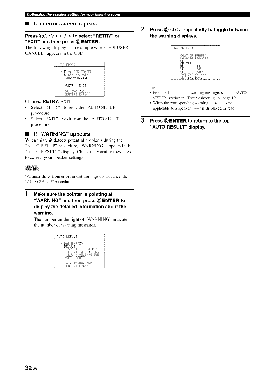
• If an error screen appears
Press @A / V / <1/ E> to select "RETRY" or
"EXIT" and then press @ENTER.
The follovdng display is an example "a,here "E-9:USER
CANCEL" appears in the OSD.
I:ILITCI_ERRCIR
÷ E-9_USER C:AIqCEL
Dolq _t oPer _lt e
_llq9 _ulqc t iolq _
iRETRY E'gZT
[ EI4TER ]_Enter
Choices: RETRY,EXIT
• Select "RETRY" to retry the "AUTO SETUP"
procedure.
• Select "EXIT" to exit from the "AUTO SETUP"
procedure.
• If"WARNING" appears
When this unit detects potential problems during the
"AUTO SETUP" procedure, "WARNING" appears in the
"AUTO:RESULT" display. Check the warning messages
to correct your speaker settings.
Press @<1 / _> repeatedly to toggle between
the warning displays.
idARHI HG;id-i
O]UT 0F F'HASE;
ee,!_Pl' :-=e Ch _dqlqei
FL --
CEHTER
F'L PR
SL SIR
SBL SI.:_R
[..4]' [_] _Select
[EHTER ] : Return
• For details about each warning message, see the "AUTO
SETUP" section in "Troubleshooting" on page 101.
• When the corresponding warning message is not
applicable to a speaker, " --' is displayed instead.
Press @ENTER to return to the top
"AUTO:RESULT" display.
Warnings diller from errors in that warnings do not cancel the
"AUTO SETUP" procedure.
Make sure the pointer is pointing at
"WARNING" and then press @ENTER to
display the detailed information about the
warning.
The number on the right of "WARNING" indicates
the number of warning messages.
AUTO: RESULT
+ I_JI_RHI 1'4G( Z ::,
RESULT
SF' = 3,4/0. i
DiST_ 14JZ_i17,0_t
LHL ; .-9=0'+6,,5dB
?SET C:l:llE:E L
[1] 'IT] _Lh: '[/o_,!n
[ EIqTER ]: Enter
32 En

This unit is equipped with 18 preset SCENE templates t_r
various situations of using this unit. As the initial factory
setting, the follov,,ing SCENE templates are assigned to
each SCENE button:
SCENE 1 : DVD Viewing
SCENE 2: Disc Listening
SCENE 3: TV Viewing
SCENE 4-: Radio Listening
If you want to use other SCENE templates, you can select
the desired SCENE templates from the SCENE template
library and assign the templates to the selected SCENE
buttons on the front panel and the remote control.
Select the desired SCENE
template
SCENE template library
(Image)
Assign the
SCENE
template to the
SCENE button
Press and hold the @SCENE (or @SCENE)
button for 3 seconds.
Tile indicator on tile selected SCENE button on tile
front panel starts to flash, and the name of the
currently assigned SCENE template appears in the
front panel display.
3 seconds 3 seconds
Front panel
or
Remote control
Rotate the @INPUT selector (or set the
operation mode selector to @AMP and then
press @<:1 / C>) to select the desired
template.
r"d ir'.= h.i.-.., , .; .-.. i i.; ....., :
L.""."L" _ i=...='.. ." & =::7 "..-" & =:::'=.=.=
3
Press the @SCENE (or @SCENE) button
again to confirm the selection.
The selected SCENE temphtte is assigned to the
SCENE button.
Front panel
or
Remote control
• If you do not carry out any operation within 30 seconds
l]'om the last operation in these steps, this procedure is
automatically canceled.
• Once the desired SCENE templates are assigned to the
corresponding SCENE buttons, you need to set the input
source of the SCENE template on the remote control. See
page 84 lor details.
Flashes
i"=i ii"z i i.; .-*._ =.; _...._"_
L""."L." "'.-" & =:::'=.=.=& _ i :::=
33 En
• Which SCENE template would you like to select?
Which source do you like to
play back?
_,_{ Video sources
(DVD video,
Recorded video)
Which component do you
like for playback? SCENE templates
DVD DVD Viewing
DVD Movie Viewing
DVD Live Viewing
DVR DVR Viewing
DVD Disc Hifi Listening
Music Disc Listening
Disc Listening
CD CD Hifi Listening
CD Listening
CD Music Listening
TUNER (FM/AM) Radio Listening
XM XM Listening
_'f Music discs (CD,
SACD or DVD-Audio)
_/_I Radio programs
Default
SCENE buttons
©
©
iPod
To et!joy XM Satellite Radio programs, you need to connect
the XM Mini-Tuner Dock (sold separately) and activate the service (see
DOCK iPod Listening
To listening to the iPod, you need Io connecl a Yamaha iPod universal
dock (sold separately) Io this unil (see page 58).
,<_f TV programs ]_,_¢<_{ DTV/CBL TV Viewing i
TV Sports Viewing i
_/_f Video t_,_,_,_,_¢1 V-AUX Action Game Playing
i
games
j -
RPG Playing i
_{ Vinyl records }_,_,_! PHONO LP Record Listening i
You can creale your original SCENE templates by' editing the preset SCENE templates. See page 36 for details.
34 En
• Preset SCENE templates descriptions
Tile illustrations of tile SCENE button ill tile following table indicate tile assigned SCENE buttons as tile default setting.
SCENE template
DVD Movie Viewing
DVD Live Viewing
DVR Viewing
Disc Hifi Listening
Music Disc
Listening
Input source
DVD*I
DVD*I
DVR
DVD*I
DVD*I
Playback mode
MOVIE
Sci-Fi
ENTERTAINMENT
Music Video
MOVIE Drama
PURE DIRECT
STEREO
2ch STEREO
Features
Select this SCENE template when you play back movies on
your DVD phlyer.
Select this SCENE template when you enjoy the music live
video on your DVD player.
Select this SCENE template when you play back movies on
your digital video recorder.
Select this SCENE template when you enjoy the high
fidelity sound of the music discs on your DVD player.
Select this SCENE template when you play back music
discs on your DVD player.
Disc Listening DVD*I STEREO Selectthis SCENEtemplateWhenyou play backmusic, •
____ 7ch STEREO I s{?urces°!!YOUrDVDp!ayeras!hebackgr°und mus!c
CD Hifi Listening CD.1 PURE DIRECT Select tiffs SCENE template when you enjoy the high
fidelity sound of the music discs on your CD player.
CD Listening CD .1 STEREO Select this SCENE template when you play back music
2ch STEREO discs on your CD player.
CD Music Listening CD .1 STEREO Select this SCENE template when you play back music
7oh STEREO source on your CD player as the background music.
Radio Lstening TUNER MUSIC Selectthi_SCENEtemplatewhmyouenjoyFMor AM
I I ENHANCER radio programs.
I 7Oh Enhancer i
XM Listening XM MUSIC Select tiffs SCENE tcmph,te when you enjoy XM Satellite
ENHANCER Radio programs.
7ch Enhancer
iPod Listening DOCK (V-AUX) MUSIC Select tiffs SCENE tcmph,te when you play back music on
ENHANCER your iPod stationed in a Yamaha iPod universal dock.
7ch Enhancer
TV Sports Viewing DTV/CBL ENTERTAINMENT Select this SCENE tcmph,te when you enjoy sports
Sports programs on your TV.
Action Game V-AUX*2 ENTERTAINMENT Select this SCENE template when you play action games
Playing Action Game such as car racing and FPS games.
RPG Playing V-AUX*2 ENTERTAINMENT Select tiffs SCENE template when you play role-playing
Roleplaying Game games.
LP Record Listening PHONO PURE DIRECT Selectthis SCENE template when you play back vinyl
records on your turntable.
When the connected DVD player or CD player has the
capability of the SCENE control signals and is connected to
the REMOTE OUT jack of this unit. this unit operates the
DVD player or CD player worked with the SCENE features.
I
'2 You can select "V-AUX" as the input source even if your iPod I
is stationed in the Yamaha Universal Dock connected to this
I
unit. When the SCENE mode is deaclivaled and your iPod is
stationed in the Yamaha Universal Dock. this unit selects
"DOCK" as the input source automatically.
35 En
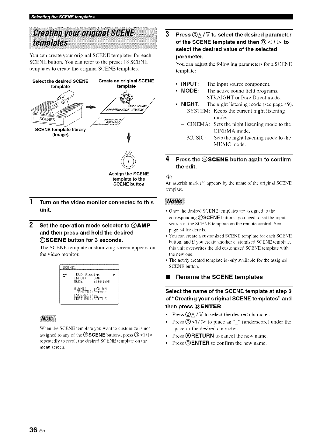
You call create your original SCENE templates for each
SCENE button. You can refer to the preset 18 SCENE
templates to create the original SCENE templates.
Select the desired SCENE
template
SCENE template library
(Image)
Create an original SCENE
template
4!,z_
Assign the SCENE
template to the
SCENE button
1 Turn on the video monitor connected to this
unit.
2 Set the operation mode selector to @AMP
and then press and hold the desired
@SCENE button for 3 seconds.
The SCENE template customizing screen appears on
the video monitor.
SCENEi
_4 DUb Ui eJ.Jin'_q
,¢ IIJPUT: DUD
HODD: STRAIGHT
HIGHT; S','STEI'I
[ EIJTER ] _ Rename
[ SC:EId---t ] _ SET
[,RI_TiJRH] : STATLIS
When the SCENE template you want to customize is not
assigned to any of the @SCENE buttons, press @<1 / C>
repeatedly to recall the desired SCENE template on the
nlell/1 screen.
Press @A / V to select the desired parameter
of the SCENE template and then @<3 / c> to
select the desired value of the selected
parameter.
You can adjust the following parameters for a SCENE
template:
• INPUT: The input source component.
• MODE: The active sound field programs,
STRAIGHT or Pure Direct mode.
• NIGHT: The night listening mode (see page 49).
SYSTEM: Keeps the current night listening
mode.
CINEMA: Sets the night listening mode to the
CINEMA mode.
MUSIC: Sets the night listening mode to the
MUSIC mode.
4 Press the @SCENE button again to confirm
the edit.
.,&
An asterisk mark (",')appears by the name ofthe original SCENE
tmnplate.
• Once the desired SCENE templates are assigned to the
corresponding @SCENE buttons, you need to set the input
source of the SCENE tmnplate on the remote control. See
page 84 lot details.
• You can create a customized SCENE template for each SCENE
button, and if you create another customized SCENE template,
this unit overwrites the old customized SCENE tmnplate with
the new one.
• The newly created template is only available for the assigned
SCENE button.
• Renamethe SCENE templates
Select the name of the SCENE template at step 3
of "Creating your original SCENE templates" and
then press @ENTER.
• Press @A/ Vto select the desired character.
• Press @<3 / C> to place an "" (underscore) under the
space or the desired character.
• Press @RETURN to cancel the new name.
• Press @ENTER to confirm the new name.
36 En

Caution
Extreme caution should be exercised when you play
back CDs encoded in DTS. If you play back a CD
encoded in DTS on a DTS-incompatible CD player,
you will only hear some unwanted noise that may
damage your speakers. Check whether your CD player
supports CDs encoded in DTS. Also, check the sound
output level of your CD player before you play back a
CD encoded in DTS.
To play [)TS-encoded CDs when using a digital audio
connectiou, set "DECODER MODE" in "INPUT MENU" to
"DTS" berate the playback (see page 80).
Belk_reperforming operations, set the operation mode selector on
the remote control to (_AMP.
2
Turn on the video monitor connected to this
unit.
-#:
See page 40 to display the input source inlk_rmation.
Rotate the @INPUT selector (or press one
of the input selector buttons (@)) to select
the desired input source.
The uame of the curreutly selected input source
appears in the front panel display for a few seconds.
Availableinputsources
i vcR Dw v-Au× DW_SL _DVD MDICD-R 10_ER CD XM PHON_
%
J
..... = ...... . J "..
Currently selected input
source
The corresponding input selector hutton on the remote
control 173rthe currently selected input source lights tip lor
approximately 5 seconds after you press any buttons on the
remote control, showing which source component is
currently being operated.
Start playback on the selected source
component or select a broadcast station.
• Refer to the operating instructions for the source
component.
• See page 50 for details about tuning instructions.
• See page 54 for details about XM Satellite Radio
tuning instructions.
Rotate @VOLUME (or press @VOLUME +/
-) to adjust the volume to the desired output
level.
• See page 48 to a_liust the level of each speaker.
• This does not affect the AUDIO OUT (REC) level.
• You can set the initial volume level and maximum volume
level (see page 77).
Rotate the @PROGRAM selector (or press
one of the sound field program selector
buttons ((_)) repeatedly) to select the desired
sound field program.
The uame of the selected sound field program appears
in the front panel display. See page 42 for details
about sound field programs.
:iii:,:::.:i.-V :i.
Currently selected _ound field program
Sound field programs cam/ot be selected when the
component connected to the MULTI CH INPUT jacks is
selected as the input source (see pa_e 38).
• Choose a sound field program based on your listening
prel'crence, not merely on the name of the program.
• When you select an input source, this unit automatically
selects the last sound fieM program used with the
corresponding input source.
• To display information about the currently selected sound
field program in the OSD. see page 61 for details.
37 En

Ila/,_.'N-4¸
• A quick guide to contents
See
When you want to...
page
Enjoy pure hi-fi stereo sound 48
A_!iust tile tonal quality of the front speakers 48
A([just tile parameters of sound field programs 61
Enjoy sources with a wide dynamic range at night 49
Use headphones 40
Enjoy multi-channel sources in 2Mmnnel stereo 49
Select a decoder to play back sources with 66
Automatically set this unit to file standby mode 41
Use this feature to turn the front speaker system (FRONT
A and/or FRONT B) on or oft'.
Press @SPEAKERS on the front panel
repeatedly to turn on or off the set of front
speakers connected to the FRONT A and/or
EXTRA SP speaker terminals.
The active front speaker set changes as follows:
I FRONT A___) FRONT B l
FRONT A
OFF _--- and
FRONT B
Use this feature to select the component connected to the
MULTI CH INPUT jacks (see page 22) as the input
SOl.lrCe.
Rotate the @INPUT selector to select MULTI CH
(or @MULTI Clt IN).
"MULTI CH" appears in the front panel disphty.
Use "MULTI CH SET" menu in "INPUT MENU' to set the
parameters Ii)r MULTI CH INPUT (see page 80).
Note
Sotmd field programs :rod the night listening mode cannot be
selected when the component connected to the MULTI CH
INPUT jacks is selected as the input source.
• FRONT A and B or FRONT B setting is not available when
"EXTRA SP ASSIGN' is set to "PRESENCE", "ZONE 2" or
"NONE" (see page 72).
• Turn off the volume level of this refit when you switch the front
speaker setting.
• Using the Zone B feature
When you set "FRONT B" to "ZONE B" (see page 72),
you can use the speakers connected to the EXTRA SP
speaker terminals in another morn (Zone B).
Press @SPEAKERS on the front panel
repeatedly to turn on or off the Zone B speakers.
When you activate the Zone B speakers, all the speakers in
the main room are muted.
• You cannot activate both the main room and Zone B speakers
simultaneously.
• If you select CINEMA DSP sound field program and activate
the Zone B speakers, Virtual CINEMA DSP activates
automatically (see page 46).
38 En

_FF/,'.!rr._;
This unit comes with a variety of input jacks. Use this
feature (audio input jack select) to switch between input
jacks when more than one input jack is assigned to as the
same input source.
_.,#._
• Wc recommend setting the audio input.jack select to "AUTO"
ill nlost cases.
• You call adjust the def:mlt audio input jack select of this nnit by
using "AUDIO SELECT" in "OPTION MENU" (see page 82).
Press @AUDIO SELECT (or @AUDIO SEL)
repeatedly to select the desired audio input jack
select setting.
Available input sources
vcR Dw v-Au× DW_SL _DW MDJ_D-R m_ER CD XM _DN
" 1........... i ....... =
I H ==$;:=i::2i_,== i"iLJ i .LJ
Currently selected audio input jack select setting
174U"['0 Automalically selects input signals in the
R)llowing order:( 1/ HDMI 12) Digilal
signals 13) Analog signals
i..._rkM_..,__a.'r Selects only HDMI si_lmls.. When HDM1
signals are nol inpul, no sound is output.
,...-...,m_"=.'"'u"'_"=...,=_o"r',...,__ Automalicallv selects input signals in the
following order: ( 1) Digital signals input
at the COAXIAL jack. (2) Digilal signals
inpul at the OPTICAL jack. When no
signals are input, no sound is outpul.
r".q'%i..i_",i".,r"n....,...-.._'%":5 Selects only analog signals. If no analog
signals are input, no sound is output.
You can display the operating information of this unit on a
video monitor.
1 Turn on the video monitor connected to this
unit.
2 Set the operation mode selector to @AMP
and then press (_DISPLAY on the remote
control.
The current status screen appears in the OSD.
STI:ITLIS UCIL_-4€_,, @dB
MOUIE
5ci-Fi
I HF'UT_ DUI)
I:I_:EEL: HDHi
HIGHT; OFF
You can select the amount of time that the current status is
displayed ill the OSD by using the "OSD-AMP" parameter
ill "OPTION MENU" (see page 81).
Note
The OSD signal is not output al the VIDEO oulput jacks and
will nol be recorded.
This feature is not available when no digital input jacks
(OPTICAL. COAXIAL and HDMI) are assigned. In addition.
HDMI is not available as an audio input jack select setting when
the HDMI IN l and HDMI IN 2.jacks arc not used. Use "I/O
ASSIGNMENT" in "INPUT MENU" to reassign the respective
input jack (see page 78).
39 En
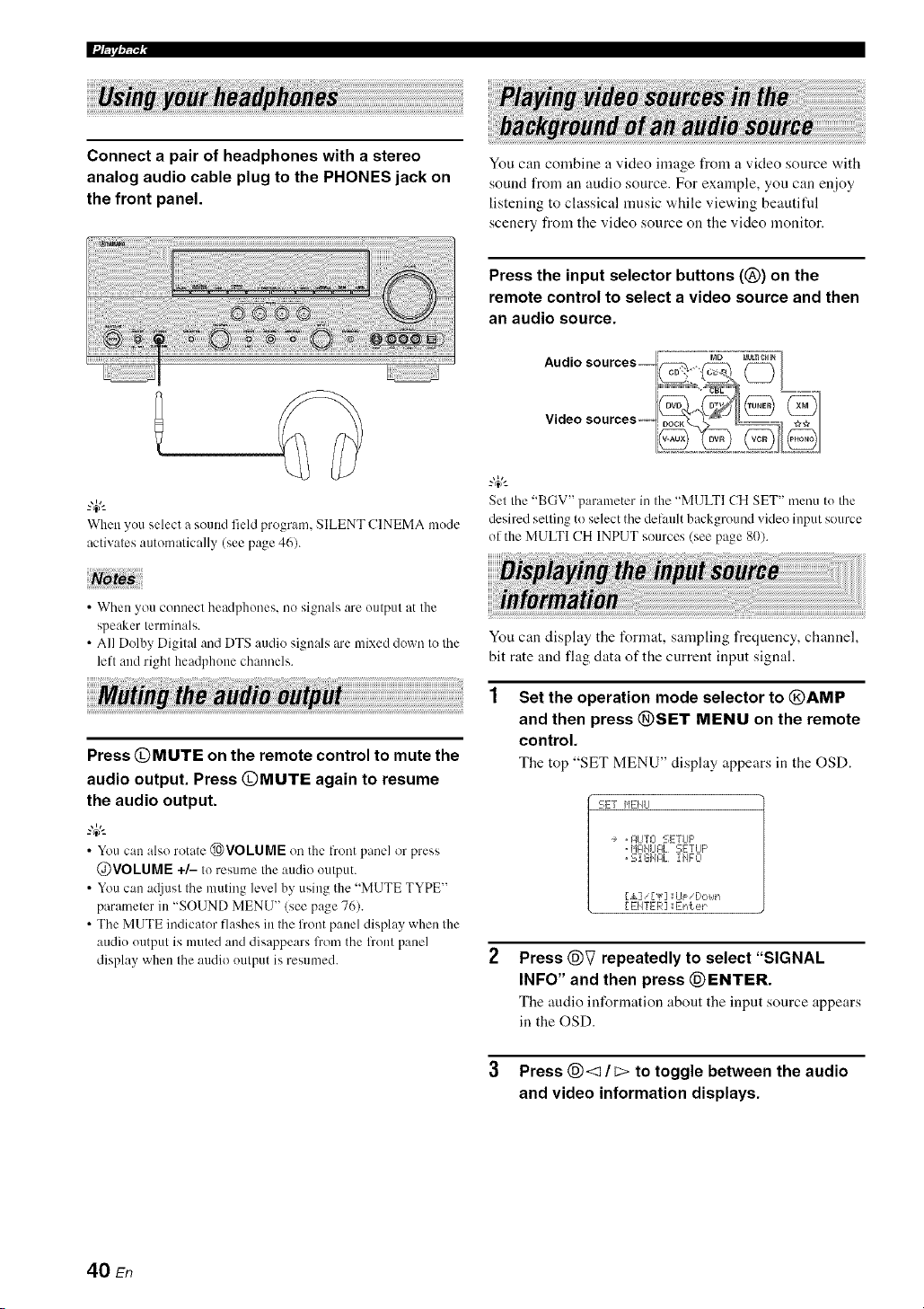
Connect a pair of headphones with a stereo
analog audio cable plug to the PHONES jack on
the front panel.
You can combine a video image from a video source with
sound from an audio source. For exainple, yon can enjoy
listening to classical music while viewing beautifid
scenery from the video source on the video monitor.
Press the input selector buttons (@) on the
remote control to select a video source and then
an audio source.
When youselect a sound field program. SILENT CINEMA mode
activates automatically (see page 46).
Set the "BGV" parameter in the "M1JLTICH SET" menu to the
desired settingto selectthe delault background video input source
of the MULTI CH INPUT sources (see page 80).
• When you connect headphones, no signals are output at the
speaker terminals.
• All DolbyDigital and DTS audio signals are mixed down to lhe
left and right headphone channels.
Press @MUTE on the remote control to mute the
audio output. Press @MUTE again to resume
the audio output.
_%,._
• You can also rotate @VOLUME on the front panel or press
@VOLUME +/- to resumethe audio output.
• Youcan a(liustthe muting level by using the "MUTE TYPE"
parameterin "SOUND MENU" (see page76).
• The MUTE indicator flashes in the front paneldisplay when the
audio output is muted and disappears from the flout panel
display when the audio output is resumed.
You can display the format, sampling frequency, channel,
bit rate and flag data of the current input signal.
Set the operation mode selector to @AMP
and then press @SET MENU on the remote
control.
The top "SET MENU" display appears in the OSD.
5E! HEI Itl
, glJTO SETLIF'
, HglI4LIFIL SETUP
, Si GIJI:IL I 1,4FO
[,&] ['lr] _iJF 'l]ot, ll'i
[ EIITER ] :IEnter
Press @V repeatedly to select "SIGNAL
INFO" and then press @ENTER.
The audio information about the input source appears
in the OSD.
3 Press @<1 / _ to toggle between the audio
and video information displays.
40 En

_FIT/,,.!rr-,_;
4 Press @SET MENU on the remote control
again to exit from "SET MENU".
• Audio information
i:::'i"li:::'h'ii"l"i" Signal fOFlIlat. Vv'hcn thi_; ul]il canl]ot dLqcct a
i ,..q'.A li"_ _
digilal signal, il aulomatically swilchcs Io
analog input.
....,::['i"li','ii:::,i,r...q,_....._.H,..._'ri..i_'::: The l]Lllllberof samples per second taken from
a conlinuous signal Io make a discrete signal.
,...ql=q'J_"lki M i::'i_r"iH i ".q..._.... The number of source channels ill tile inpul
signal (fionl/surround/LFE). For example, a
mulli-channel soundtrack wilh 3 front
channels, 2 surround channels and LFE, is
displayed as "31210.1".
_...,i:::'._.'r"r'_::,,"¢r_::'_r..r'.,__.... The number of bits passing a given poillt per
second.
li::'il..,m,...i_"'_'::: Fhtg dala encoded in DTS, Dolbv Digital or
PCM signals tirol cue Ihis unil to automalically
switch decoders.
"---" appears when this ttnil cannot display the corresponding
information.
• Video information
Hi){"[]i {:;i:i!![:!!i,, Rcsoltltion or"the HDMI sign:ds input or
output at the HDMI IN/OUT jacks of this
unit.
Hi){"i]i {!!!IP.F;?.II){:?. Error message for HDMI sourcesor
connected HDMI devices. See page 101
for details.
Use this feature to automatically set the main zone to the
standby mode alter a certain amount of time. The sleep
timer is useful when you are going to sleep while this unit
is playing or recording a source. The sleep timer also
automatically turns off any external components
connected to the AC OUTLET(S) (see page 24).
Set the operation mode selector to @AMP and
then press @SLEEP repeatedly to set the
amount of time.
Each time you press @SLEEP, the front panel display
changes as shown below.
/71/717 Tii: '17
The SLEEP indicator flashes while you are switching the
amount of time for the sleep timer. Once the sleep timer is
set, the SLEEP indicator lights up in the front panel
display, and the display returns to the selected sound field
program.
Flashes
SLE_
Lights up
SLEEP
¢" 'T' ["_ ¢"_ T (" _ _ "r' _ I .....
• Canceling the sleep timer
Press (_)SLEEP on the remote control repeatedly
until "SLEEP OFF" appears in the front panel
display.
Disappears
:iii;i....iiiilEF::' 0F::F:
The SLEEP indicator turns oft', and "SLEEP OFF"
disappears from the front panel display after a few
seconds.
"4¢--
The sleep timer setting can also be canceled by pressing
@STANDBY (or @MAIN ZONE ON/OFF) to set the main
zone to the standby mode.
41 En
This unit is equipped with a variety of precise digital decoders that allow you to enioy multi-channel playback from
almost any stereo or multi-channel sound source. This unit is also equipped with a Yamaha digital sound field processing
(DSP) chip containing several sound fiekt programs which you can use to enhance your playback experience.
• The Yamaha HiFi DSP sound field programs recreate real-world acoustic environments made fronl precise measurenmnts taken in
actual concert halls, music venues, movie theaters, etc. Thus. you may notice variations in the strength of the reflections coming fi'om
the front, back. left and right.
• You can change sound field parameters. See page 61 for details.
Rotate the (}9PROGRAM selector (or set the
operation mode selector to @AMP and then
press one of the sound field selector buttons ((_)
repeatedly).
The name of the selected sound field program appears in
the front panel display and in the OSD.
Noto
• When you selecl an input source, this trait automatically selecls
the last sound field progrmn used with lhe corresponding input
SOtlrce.
• Sound field programs cannot be selected when the component
connected to the MULTI CH INPUT.jacks is selected as the
input source (see page 38).
• When you play back DTS 96/24 sources with ally sound field
program, this unit applies the selected program without
activating the DTS 96/24 decoder.
• Sampling frequm_cies higher than 48 kHz are sampled down to
48 kHz or lower and then sound field programs are applied.
• When the sampling frequency of the input sources are higher
than 96 kHz. this unit does not apply ally sound field programs.
Selecl a sound field progran/based on your listening prel-erence, not merely on Ille name ol Ille program, etc.
CINEMA DSP
Remote control Category of the Name of the Created sound or
button program program fields HiFi DSP
-I ..... ! "
(?9 H,:<E
This program clearly reprodnces tl_e finely elabomled sound design of Ille latest science fiction and special effects l_'alming movies
Yotl can enioy a variel_ of cinemalographically cleated viHnal space_ leproduced with clem sepmalion belween dialog, sound efl_cls and
I>ackgl otllld music
DSP LEVEL P.ROOM SIZE S. ROOM SIZE
P.INIT.DLY S.INIT. DLY SB INf. DLY
i
Available sound field parameters (see page 63)
SB ROOM SIZE
DIALG. LIFT
!
Program description
Sound field indicators
Presence sound field
. Listening position
Surround left C_,_ Surround
ri_hl
sound field sound field
Surround back sound field
42 En

• For audio music sources
-#..
Rrffgiff:/_'.l.,o.,,_.,,_
• The available sound field parameters dillcr depending oil the settings of the speakers.
• "DIALG.LIFT" is available only when "EXTRA SP ASSIGN" in "SPEAKER SET" is set to "PRESENCE" (see page 72).
CLASSICAL _"'i ,"_':::":::''i",='_",i H,::_ I I 'I i"] r"li ,ii'_ 'i _",I'_ []
Q7 } ...............,......................,, HiFi DSP
This soundfield sinm]atesa concert hall with approximately 2500 seatsin Munich. using stylish wood for the interior finishing asnormal
standardsfor Europeanconcert halls. Fine. beautifil] reverberationsspreadrichly, creating a cahning atmosphere.The listener's villual seatis
at the center left of the arena.
DSP LEVEL ROOM SIZE DIALG.LIFT
INIT. DLY LIVENESS
[ 1..........1 " [Q_) ...............,.....................,, HiFi DSP
This is an approximately 170()-seated, middle-sized concert hall with a shoebox shape that is traditional in Vienna. Pillars and ornate car_ ings
create extremely complex reflections from all around the audience, producing a very fllll, rich sound.
DSP LEVEL ROOM SIZE DIALG.LIFT
INIT. DLY LIVENESS
CLASSICAL I"'i r'l=:::'_:::' '}'l=.l"li I :h,:::_i','ll"il::_J ,'* []
Q) ..........."'..................."'.................... HiFi DSP
This program creates a relatively _xide space with a high ceiling like an audience hall in a palace. It offers pleasant reverberations that are
suitable for courtly music and chamber music.
DSP LEVEL LIVERESS REV.DELAY DIALG.LIFT
INIT. DLY REV.TIME REV. LEVEL
......... 1 .. [(_ ........",,........................................... [] HiFi DSP
This program simulates a live house with a low ceiling and homey atmosphere. A realistic, live sound field features powerful sound as if the
listener is in a row in front of a small stage.
DSP LEVEL ROOM SiZE DIALG.LIFT
INIT. DLY LIVENESS
'ih e ...... il_e.ii.:.,i:..i."e
LIVE/CLUB i T i i]:::' ,,q"q i ii:::, l,=:,r,t*:,:._...i []
(_ ........".",.......................... HiFi DSP
This is the sound field of a rock music live house in Los Angeles, with approximately 46(1 seats. The listener's virtual scat is at the center left
of the hall.
DSP LEVEL ROOM SIZE REV.TIME REV. LEVEL
INIT. DLY LIVENESS REV.DELAY DIALG.LIFT
[ I ....... 1 " [
LIVE/CLUB i T i ii:::' ..'a=q i ii:::' "F_"]I:::' Hr't'l',]',l"ff,=l 'I i"ll:::, []
Q_) .........,,................................ HiFi DSP
This is Ihe sound field at stage front in The Bottom Line, a famous New Yorkjazz chlb. The floor can scat 300 people to the lefi and right in a
sound field offering real and vibrant sound.
DSP LEVEL ROOM SIZE DIALG.LIFT
INIT. DLY LIVENESS
43 En
l',-x,lrlit, it_!l;I,,illi, llqli/_
• For various sources
Notes
• The available sound field parameters and the created sound fields differ depending on the input sources and the settings of this unit.
• "DIALG.LIFT" is available only when "EXTRA SP ASSIGN" in "SPEAKER SET" is set to "PRESENCE" (see page 72).
.........1 l- I " 1
Q9 Ei"4TERTI::4:i:i"4MEI".iT ::::,i:::.o i.%:iii. _._ [C,N_MA_
This progrum allows the listeners to enjoy stereo sport broadcasts and studio variety programs with enriched live feeling. In sports broadcasts,
the voices of the commentator and sportscaster are positioned clearly at the center while the atmosphere of the stadium expands in an
optimum space to offi:r the listeners with a feeling of presence in the stadium.
DSP LEVEL P. ROOM SIZE S. ROOM SIZE SB ROOM SIZE
P. INIT. DLY S. INIT. DLY SB INI. DLY DIALG.LIFT
.........1 [ ........ j A [(_ Ei.4TERTF4:i:i.4MEbiT H,....,..,,...,_...,H.:::,,.,.,.... {,,_._ I,:,,,,,_,,.,,A.2_
This sound field has been suitable for action games such as car racing and FPS games. It uses the reflection data that limits the effects range
per channel in order to off'ora powerfld playing environment with a beingqhere feeling by enhancing various effects tones while maintaining
a clear sense of directions.
DSP LEVEL P. ROOM SIZE S. ROOM SIZE SB ROOM SIZE
P. INIT. DLY S. INIT. DLY SB INI. DLY DIALG.LIFT
.........1 t " 1(_ Ei.4IERII::4]:i.4MEbiT ;;:,:::,:i.,_?F::i.a'::<i.r,g):!!iar,_,_ _,,,_._ Ic=,_g_ll
This sound field has been suitable for role-playing and adventure games. It combines the sound field el'l_,ctsfor movies and the sound field
designs for "Action Game" to represent the depth and 3D feeling of the field during play, while ofl_:ring movie-like surround effects in the
movie scenes in the game.
DSP LEVEL P. ROOM SIZE S. ROOM SIZE SB ROOM SIZE
P. INIT. DLY S. INIT. DLY SB INI. DLY DIALG.LIFT
• For visual sources of music
Notes
• The available sound field parameters and the created sound fields differ depending on the input sources and the settings of this unit.
• "DIALG.LIFT" is available only when "EXTRA SP ASSIGN" in "SPEAKER SET" is set to "PRESENCE" (see page 72).
.........1 l ....... I " 1(29 i!!:HrE):_m=,':i:i.iME)..rr""'.":::.",. '.'",',:',' {@} )_,_.m_
This sound field offers an image of a concert hall for live performance of pop, rock and jazz music. The listener can indulge oneself in a hot
live space thanks to the presence sound field that emphasizes the vividness of vocals and solo play and the beat of rhythm instruments, and to
the surround sound field Ihat reproduces the space of a big live halh
DSP LEVEL P. ROOM SIZE S. ROOM SIZE SB ROOM SIZE
P. INIT. DLY S. INIT. DLY SB INI. DLY DIALG.LIFT
44 En

• For movie sources
Youcan select the desired decoder used with following sound field program (except "Mono Movie"). See page 66 for details.
• The available sound field parameters and the created sound fields difli:r depending on the input sources and the settings of this unit.
• "DIALG.LIFT" is available only when "EXTRA SP ASSIGN" it/"SPEAKER SET" is set to "PRESENCE" (see page 72).
..... [ I ...... 1 [
This program creates a sound field emphasizing the surrounding fi:eling without disturbing the original acoustic positioning of multi-dlannel
audio such as Dolby Digital and DTS. It has been designed with the concept of "an ideal movie theater", in which the audience is surrounded
by beautiful reverberations from the left, right and rear.
DSP LEVEL S. ROOM SIZE SB INI. DLY SB LIVENESS
S. INIT. DLY S.LIVENESS SB ROOM SIZE DIALG.LIFT
......[ 1 1 " [
This program represents the spectacular feeling of large-scale movie productions.
It reproduces a broad theater sound field matching the cinemascope and wider-screen movies with all excellent dynamic range from very
small to extremely large sound.
DSP LEVEL P. ROOM SIZE S. ROOM SIZE SB ROOM SIZE
P. INIT. DLY S. INIT. DLY SB INI. DLY DIALG.LIFT
..... [ 1 1 " [
................................ _.€,,_ i_,._,,=m=
This program clearly reproduces the finely elaborated sound design of the latest science fiction and special efli:ctsqcaturing movies.
You can mtioy a variety of cinematographically created virtual spaces reproduced with clear separation between dialog, sound effects and
background music.
DSP LEVEL P. ROOM SIZE S. ROOM SIZE SB ROOM SIZE
P. INIT. DLY S. INIT. DLY SB INI. DLY DIALG.LIFT
..... [ 1 1 " [Q_) M0Ui i!!: ch..4,..,,:::,_...,.i..,_...,.... _,_.,_ io,,,_,,,,A.:_
This program is ideal fi_r precisely reproducing the sound design of action and adventure movies.
The sound field restrains rexerberations but puts emphasis on reproducing a powerful space expanded widely to the lefi and right. The
reproduced depth is also restrained relatively to ensure the separation between audio channels and the clarity of the sound.
DSP LEVEL P. ROOM SIZE S. ROOM SIZE SB ROOM SIZE
P. INIT. DLY S. INIT. DLY SB INI. DLY DIALG.LIFT
......[ 1 1 " [(Z) i,i,:::,,..J:i:E: i:::,,.-._,,...,._..., C@.} >''_""..,._
This sound field features stable reverberations that match a wide range of movie genres from serious dramas to musicals and comedies. The
re'_erberations are modest but offer all optimum 3D feeling, reproducing effects tones and background music softly but cubically around clear
words and center positioning ill a way that does not fatigue the listener even afier long hours of viewing.
DSP LEVEL P. ROOM SIZE S. ROOM SIZE SB ROOM SIZE
P. INIT. DLY S. INIT. DLY SB INI. DLY DIALG.LIFT
..... A
IIOVIE Ml"ii i T i:::' l"]i"li"ll='i P'h"ti.j 'I I:::' [] I ClNEIMiA_
i l_,J',/,i, i ....
This progrlim is provided for reproducing lilOnil/iril] video sources such :is a classic lnovie ill :111atmosphere of ii good old lnovie theater.
The program produces the optimum expansion and reverberation to the original audio to create a comfortable space with a certain sound
depth.
DSP LEVEL ROOM SIZE REV.TIME REV. LEVEL
INIT. DLY LIVENESS REV.DELAY DIALG.LIFT
45 En
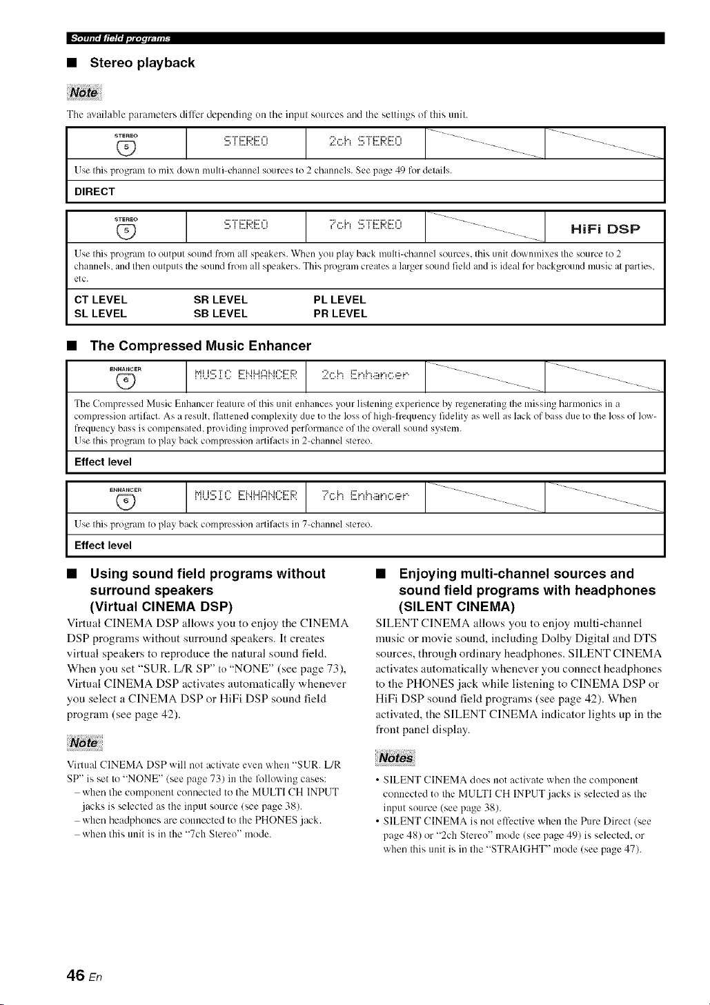
Ix, irlir, lt_l',l,,li, lfllil-
• Stereo playback
The available pal'ameters dilfer depending on the inpul sources and the settings ol this unit.
Use Ihis program Io mix down multi=channel sources to 2 channels. See page 49 for details.
DIRECT
...... 1 [ J 1
,: "r'i:::'i::,i:::'r, '7,".i.",'::7i7::'i:;?i:I"I .... _--
HiFi DSP
Use Ihis l_rogram Io outpul sound from all speakers. When you play back multi-channel sourcl:s, Ihis unit downmixes Ihe source to 2
channels, and Ihenoulpuls the sound from all speakers. This program creates a larger sound field an(l is ideal for background music al parties,
etc.
CT LEVEL SR LEVEL PL LEVEL
SL LEVEL SB LEVEL PR LEVEL
• The Compressed Music Enhancer
1 [ J----
_._.c_ i.,.iii,::rT,". i::ri..ii...i,",i..ir'i::ri:::,";:',".h i:::'i',i",.:::,_",,".,:::,_"
Q_ I l_.,i,.J ,i, _.,, i..i 'ii ii,,_i _.,,i,.=i,><
The Compressed Music Enhancer feature of this unit enhances your listening experience by regenerating the missing harmonics in a
compr_:ssion artil,_ct. As a result, flattened complexity due to the loss of high-frequency fidelity as well as lack of bass due to the loss of low-
frquency bass is compensated, providing improved performance of the overall sound system.
Use this program to play back compression artil,_cts in 2-channel stereo.
Effect level
ENHANCER
O
Use Ihis program Io play back compression arlifacls in 7-channel stereo.
Effect level
1 [ J........ 1 ]
/
• Using sound field programs without
surround speakers
(Virtual CINEMA DSP)
Virtual CINEMA DSP allows you to enjoy the CINEMA
DSP programs without surround speakers. It creates
virtual speakers to reproduce the natural sound field.
When you set "SUR. L/R SP" to "NONE" (see page 73),
Virtual CINEMA DSP activates automatically whenever
you select a CINEMA DSP or HiFi DSP sound field
program (see page 42).
Note
Virtual CINEMA DSP will not :_ctivate even when "SUR. L/R
SP" is set to "NONE" (see page 73) in the following cases:
when the component connected to the MULTI CH INPUT
jacks is selected as the input source (see page 38).
when headphones are connected to the PHONES jack.
when this unit is in the "7ch Stereo" mode.
• Enjoying multi-channel sources and
sound field programs with headphones
(SILENT CINEMA)
SILENT CINEMA allow,s yon to enjoy multi-channel
music or movie sound, including Dolby Digital and DTS
sources, through ordinary headphones. SILENT CINEMA
activates automatically whenever you connect headphones
to the PHONES jack while listening to CINEMA DSP or
HiFi DSP sound field programs (see page 42). When
activated, the SILENT CINEMA indicator lights up in the
front panel display.
• SILENT CINEMA does not activate when the component
connected to the MULTI CH INPUT.jacks is selected as the
input source (see page 38).
• SILENT CINEMA is not ell-cctive when the Pure Direct (see
page 48) or "2ch Stereo" mode (see page 49) is selected, or
when this unit is in the "STRAIGHT" mode (see page 47).
46 En

When this unit is in the "STRAIGHT" mode, 2-channel
stereo sources are output from only the front left and right
speakers. Multi-channel sources are decoded straight into
the appropriate channels without any additional effect
processing.
Press @STRAIGHT (or @STRAIGHT) to select
"STRAIGHT".
.::_ i r_:.H J. C:U"i i
• Deactivating the "STRAIGHT" mode
Press @STRAIGHT (or @STRAIGHT) so that
"STRAIGHT" disappears from the front panel
display.
The sound effect is turned back on.
47 En
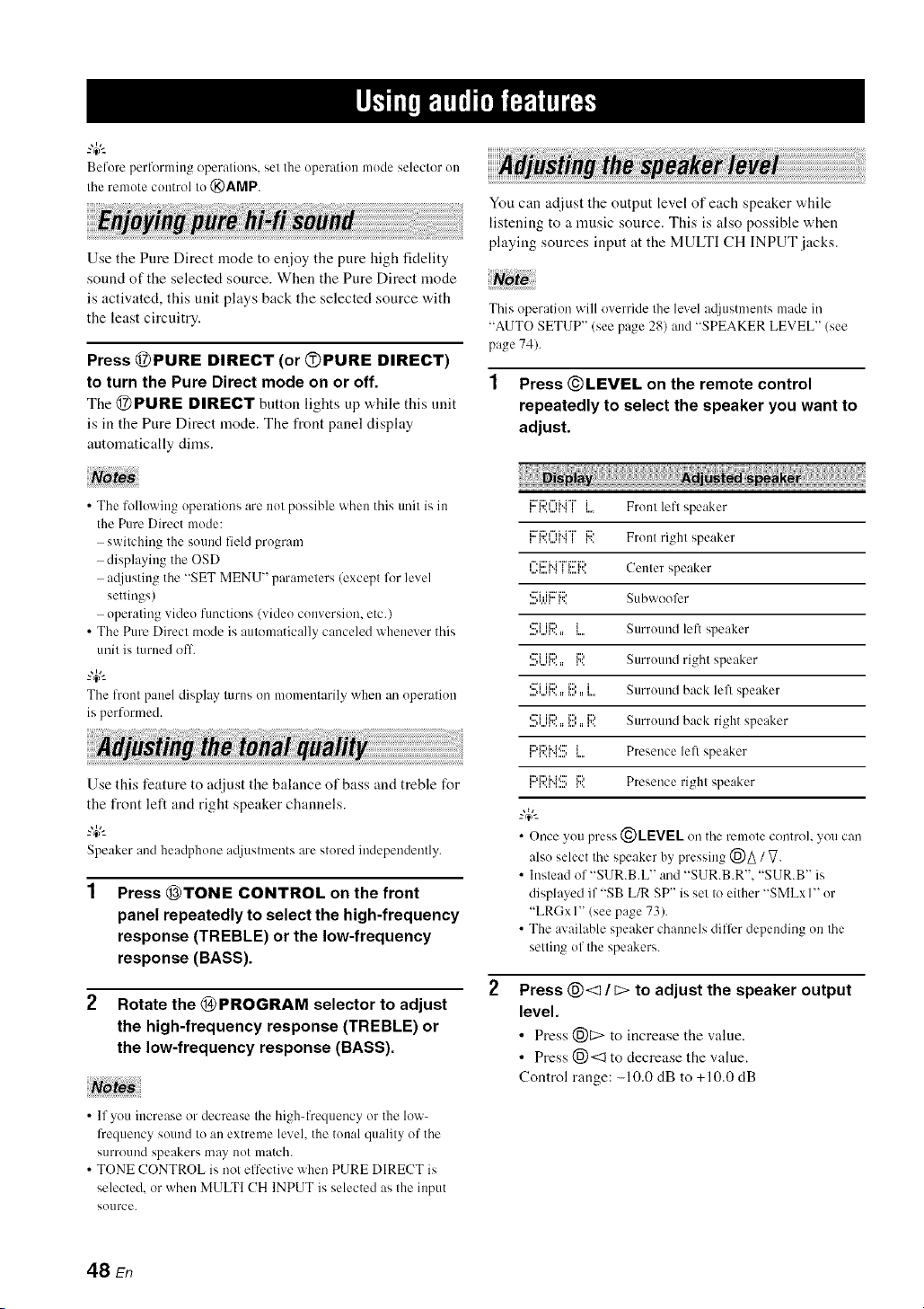
Before perfcwming operations, set Ille operation mode selector on
Itae remote control to @AMP.
Use the Pure Direct mode to enjoy the pure high fidelity
sound of the selected source. When the Pure Direct mode
is activated, this unit plays back the selected source with
the least circuitry.
Press @PURE DIRECT (or OPURE DIRECT)
to turn the Pure Direct mode on or off.
The @PURE DIRECT button lights up while this unit
is in the Pure Direct mode. The front panel display
automatically dinas.
You can adjust the output level of each speaker while
listening to a music source. This is also possible when
playing sources input at the MULTI CH INPUT jacks.
This operation will override Ihe level a@lstmenls made in
"AUTO SETUP" (see page 28) and "SPEAKER LEVEL" (see
page 74).
1 Press ©LEVEL on the remote control
repeatedly to select the speaker you want to
adjust.
• The following operations are not possible when this trait is in
the Pure Direct mode:
switching the sound field program
displaying the OSD
atliusting the "SET MENU" parameters (except fl)r level
settings)
operating video functkms (video conversion, etc.)
• The Pure Direct mode is automatically canceled whenever this
unit is turned off.
"4¢--
The front p:mel display turns on moment:wily whm_ :m operation
is performed.
Use this feature to adjust the balance of bass and treble for
the front left and right speaker channels.
"4¢'-
Speaker and headphone a@lstments are stored inclependm/tly.
Press @TONE CONTROL on the front
panel repeatedly to select the high-frequency
response (TREBLE) or the low-frequency
response (BASS).
Rotate the @ PROGRAM selector to adjust
the high-frequency response (TREBLE) or
the low-frequency response (BASS).
• If you increase or decrease the high-frequency or the low-
l?equency sound to an extreme level, the tonal quality of the
surround speakers may not match.
• TONE CONTROL is not elt'ective when PURE DIRECT is
selected, or when MULTI CH INPUT is selected as the input
source.
Ii:::'E)¢"li..i"i"l'..'...q ",' I Ii.... Front lefl speaker
li::'_:::'"%'i°i"v......,".,i v..i:::' Front right speaker
' "_""_' _"_.... C p k
,...._....i".,__....v.. enler s ea er
,...i.,,... ,..., Subwoofer
....,*.,.q v,,
................'::_1ii:?.. { Surround left speaker
,:::'iii:::, _::, Surround right speaker....,*,..q',, :: i%
,:::_ii:::,_::, i Surround back left speaker
....,*...q',, :: i..., :: i....
,::?i iiD i1::, iD Surround back right speaker....,*...q',, :: i..., :: v,,
,i::'i:::'i"i'::rr..,_....,_i Presence lefl speaker
,c:'_::'i"_':::'r..,_....,r.._::' Presence righl speaker
_.,&
• Once you press (_)LEVEL on the remote control, you can
also select the speaker by pressing (_)_ / V.
• Instead of "SUR.B.L" and "SUR.B.R'. "SUR.B" is
displayed if "SB L/R SP" is set to either "SMLxI" or
"LRGxI" (see page 73).
• The available speaker chammls differ depending on the
setting of the speakers.
Press @<1 / c> to adjust the speaker output
level.
• Press (_)C> to increase the value.
• Press 1_)<::1to decrease the value.
Control range: -10.0 dB to +10.0 dB
48 En
P_Tffl.m_lrt.l_lt_s_t_
You can mix clown multi-channel sources to 2 channels
and enjoy playback in 2-channel stereo.
Press ®STEREO on the remote control
repeatedly to select "2ch Stereo".
--'4:--
• YO/1 can use a s/lbwoofer with tiffs prugrmn whm) "LFE/BASS
OUT" is set to "SWFR" or "BOTH" (see page 74).
• You can also select the "2ch Stere()" mode by rotating the
@ PROGRAM selector on the front panel.
• See page 66 lot details about lhe parameters of lhe "2ch Stereo'
mode.
• You cannot use the night listening modes in the lollowiug
cases:
when the Pure Direct mode (see page 48) is selected.
when the component connected to the MULTI CH
INPUT jacks is selected as the input source (see
page 38).
when headphones are connected to the PHONES .jack.
• The night listening modes may vary in effectiveness
dependiug on the input source and surround sound settings
yOU use.
The night listening modes are designed to improve
listenability at lower volumes or at night.
1 Press ®NIGHT on the remote control
repeatedly to select "NIGHT:CINEMA" or
"NIGHT:MUSIC".
2
Choices: NIGHT:CINEMA, NIGHT:MUSIC, OFF
• Select "NIGHT:CINEMA" when watching films to
reduce the dynamic range of film soundtracks and
make dialog easier to hear at lower volumes.
• Select "NIGHT:MUSIC" when listening to music
sources to preserve ease-of-listening for all sounds.
• Select "OFF" if you do not want to use this feature.
--'4:--
When a night listening mode is selected, the NIGHT
indicator lights up in the l?ont panel display.
Press @<1 / c> to adjust the effect level while
"NIGHT:CINEMA" or "NIGHT:MUSIC" is
displayed in the front panel display.
F" r', r', ....... L _ , , '_ ==_..4T F.,
E_.T' T' _:::=L., L, ==L.._..._ .i. =, i'i .i.i... _
Choices: MIN, MID,MAX
• Select "MIN" for minimum compression.
• Select "MID" for standard compression.
• Select "MAX" for maximum compression.
--'4:--
"NIGHT:CINEMA" and "NIGHT:MUSIC" a@lstments are
stored independm/tly.
49 En

There are 2 tuning methods: at]tomatic and manual. Automatic tuning is effective when station signals are strong and
there is no interference. If the signal from the station you want to select is weak, tune into it manually. You can also use
the automatic and manual preset tuning features to store up to 40 stations (AI to ES: 8 preset station numbers in each of
the 5 preset station groups). Furthermore, you can recall any preset stations and exchange the assignment of two preset
stations with each other.
Orient the connected FM and AM anlennas JOl*lhe best reception.
Automatic tuning is effective when station signals are
strong and there is no interference.
1 Rotate the @INPUT selector on the front
panel to select "TUNER" as the input source.
2 Press @FM/AM to select the reception band.
"FM" or "AM" appears in the front panel display.
3 Press @TUNING AUTO/MAN'L so that the
AUTO indicator lights up in the front panel
display.
Lights up
_:i[iUi" V ,;;:=,;;:===..-" _ H i.=:..
NOcolon (:)
It" a colon (:) appears in the front panel display, tuning
is not possible. Press @PRESET/TUNING to turn
the colon (:) off.
Press @PRESET/TUNING/CH <:3 / C> once
to begin automatic tuning.
When this unit is tuned into a station, the TUNED
indicator lights up and the frequency of the received
station is shown in the front panel display.
• Press @C> to tune into a higher freqnency.
• Press @<1 to tune into a lower frequency.
If the signal received from the station you want to select is
weak, tune into it manually.
Manually tuning into an FM station automatically switches the
tuner to monaural reception to increase the signal qualily.
Rotate the @INPUT selector on the front
panel to select "TUNER" as the input source.
Press @FM/AM to select the reception band.
"FM" or "AM" appears in the front panel display.
Press @TUNING AUTO/MAN'L so that the
AUTO indicator disappears from the front
panel display.
i"il IV" i'i ,.::=,..:=== 7 = Vii"i.=:..
NO colon (:)
lfa colon (:) appears in the front panel display, tuning
is not possible. Press @PRESET/TUNING to turn
the colon (:) off.
Press @PRESET/TUNING/CN <1 / [> to
tune into the desired station manually.
_.,#._
Hokl down the button to contilme searching.
50 En
Nr_T?_l_,rt_ff_,
You can use the automatic preset tuning feature to store up
to 40 FM stations with strong signals (AI to ES: 8 preset
station numbers in each of the 5 preset station groups) in
order. You can then recall any preset station easily by
selecting the preset station number.
1 Rotate the @INPUT selector on the front
panel to select "TUNER" as the input source.
2 Press @FM/AM to select "FM" as the
reception band.
"FM" appears in the front panel disphty.
3
Press and hold @MEMORY for more than 3
seconds.
The preset station number as well as the MEMORY
and AUTO indicators flashes. After approximately 5
seconds, automatic presetting starts from the current
frequency and proceeds toward higher frequencies.
Flashes
_"_i"i =, Z':. *i C:,g:, ,7. :.*L.... -
___== _ _ i :,,.=:,,.= := ,,-" _ H L=L.
Flashes
When automatic preset tuning is completed, the front
panel display shows the frequency of the last preset
station.
_.,#._
• You can specil}, the preset number from which this unit
stores FM stations. Press @AIBICIDIE and then
@PRESET/TUNING/CH <:1/ E> repeatedly after you
perlk_rm step 3 to select the preset station number under
which the first station will be stored.
• You can begin tuning toward lower lbequencies to store
FM stations autonmtically. Press @PRESET/TONING
so that the colon (3 disappears lhom the lhont panel
display and then press @PRESET/TLINING/CH <:1alter
pressing and holding @MEMORY for more than 3
seconds.
• Any stored station data existing under a preset station
number is cleared when you store a new station under the
santo preset station utlmber.
• If the number of received stations does not reach 4(1(E8),
automatic preset tuning automatically stops after
searching lot all the available stations.
• Only FM stations with sufficient signal strength are stored
automatically by autonmtic preset tuning. If the station
you want to store is weak in signal strength, tune into it
manually and store it as described in "Manual preset
tuning" below.
You can also store up to 40 stations (AI to ES: 8 preset
station numbers in each of the 5 preset station groups)
manually.
1 Tune into a station.
See page 50 for tuning instructions.
2 Press @MEMORY on the front panel.
The MEMORY indicator flashes in the front panel
display for approximately 10 seconds.
..... MEMORY .....
Flashes
Press @A/BIClDIE repeatedly to select a
preset station group (A to E) while the
MEMORY indicator is flashing.
The selected preset station group letter appears.
Check that the colon (:) appears in the front panel
display.
Flashes
_"= =, ::7:. *i ,:::-:::, ,::'. :.*L_.-
;"= " " _ i :.,.=:.,.= == .,-" _ H L=:..
=
Preset station Colon (:)
group
51 En
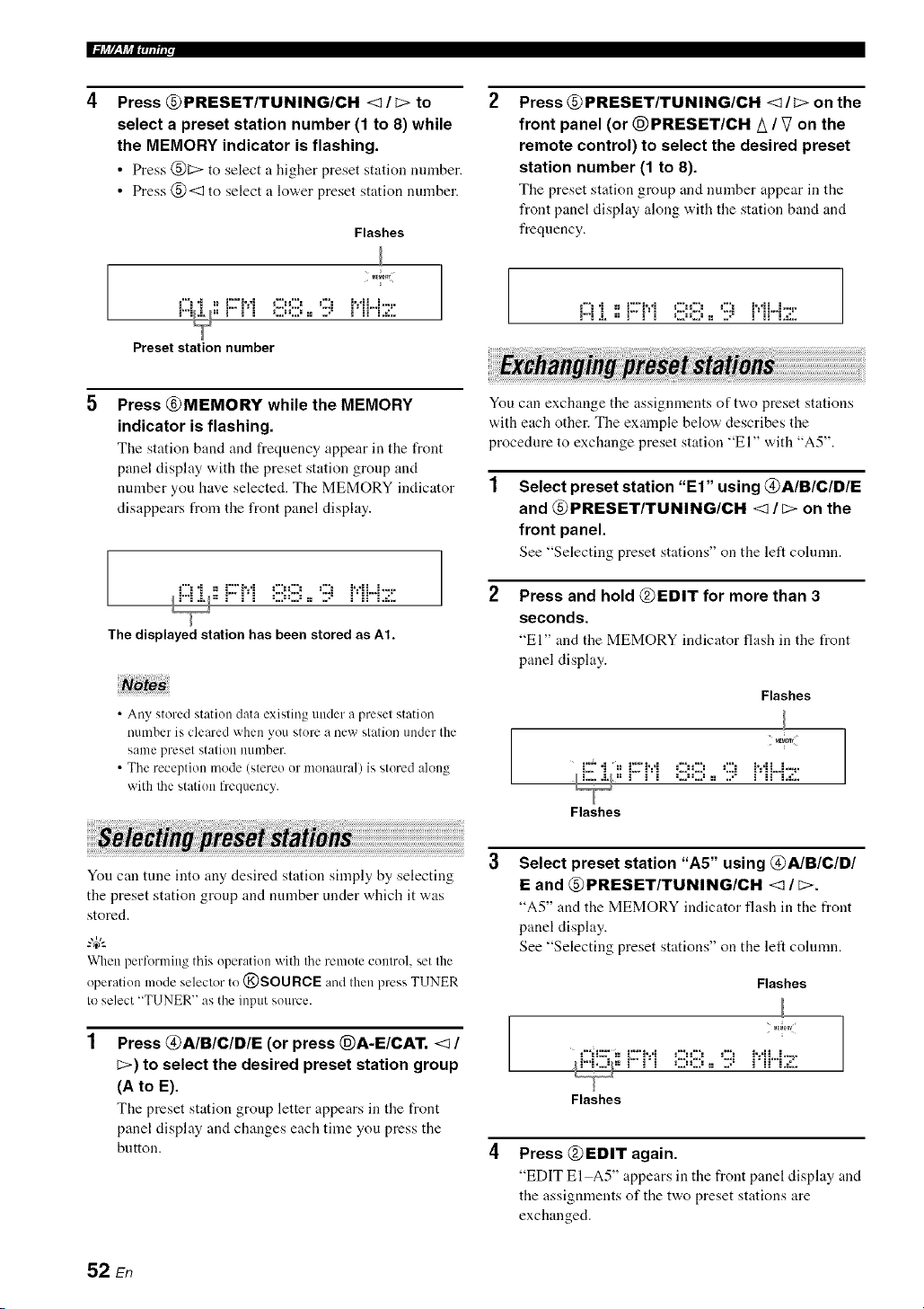
I.%_ f/__YJ_Em;lur
Press @PRESET/TUNING/CH <1 / C> to
select a preset station number (1 to 8) while
the MEMORY indicator is flashing.
• Press @[::> to select a higher preset station mnnber.
• Press @<1 to select a lower preset station number.
Flashes
M_M_RY
Preset station number
Press @PRESET/TUNING/CH <1/C> on the
front panel (or @PRESET/CH A / V on the
remote control) to select the desired preset
station number (1 to 8).
The preset station group and uumber appear in the
front panel display along with the station band and
frequency.
!-! "i =_iZ'?:*i OO ,2! i':*ii...i-._-
F"i & == _ _ i :,..=:,..= := ,.-" _ H L=L.
Press @MEMORY while the MEMORY
indicator is flashing.
The station band and frequency appear ill the front
panel display with the preset station group and
nmnber you have selected. The MEMORY indicator
disappears from the front panel display.
._"!"i ==.Z'.v i OO ,7. i'dL.i.-_-
I_ == _ _ i :,..=:,..= := ,.-" _ H L:L.
The displayed station has been stored as At.
• Any stored station data existing under a preset station
number is cleared when you store a new station under the
same preset station nllmber.
• The reception mode (stereo or monaural) is stored along
with lhe station frequency.
You can exchange tile assignmeuts of two preset stations
w,ith each other. The example below describes the
procedure to exchange preset station "El" with "A5".
Select preset station "El" using @A/B/C/DIE
and @PRESET/TUNING/CH <1/C> on the
front panel.
See "Selecting preset stations" on the left cohnnn.
Press and hold @EDIT for more than 3
seconds.
"El" and the MEMORY indicator fhtsh in the t_ont
panel display.
Flashes
MEM_nY
{:2""i =, {Z'i'=*i OO ,:2E :.*L._...
I L... &/== _ _ i :,..=:,..= := ,." _ i_ L=L.
Flashes
You can tune into any desired station simply by selecting
the preset station group and number under which it was
stored.
When performing this operation with the remote control, set the
operation mode selector to @SOURCE and then press TUNER
to select "TUNER" as the input source.
Press @AIBICID/E (or press @A-E/CAT. <1 /
C>) to select the desired preset station group
(A to E).
Tile preset station group letter appears in tile front
panel display and changes each time you press the
button.
Select preset station "A5" using @A/B/C/D/
E and @PRESET/TUNING/CH <1 / _>.
"A5" and tile MEMORY indicator flash ill the t¥ont
panel display.
See "Selecting preset stations" on the left cohmm.
Flashes
M_RY
i_l = _ _ i :,..=:,..= := ,.-" _ H L=L.
Flashes
Press @EDIT again.
"EDIT El A5" appears in the front panel disphty and
the assignments of the two preset stations are
exchanged.
52 En

XM Satellite Radio offers an extraordinary variety of commercial-free music, plus the best in sports, news, talk and
entertainment. XM is broadcast in superior digital audio from coast to coast. From rock to reggae, from classical to hip
hop, XM has something for every music fan. XM's dedication to playing the richest selection of music is matched by its
passion for live sporting events, talk radio, up-to-the-minute news, stand-up comedy, chiktren's programming, and much
more.
For U.S. customers, information about XM Satellite Radio is available online at wwv<xmradio.conl.
For Canadian customers, information about XM Canada is online at www.xmradio.ca.
This unit is equipped with the Neural Surround decoder that plays back the XM HD surround sound content of the XM
Satellite Radio broadcasts in multi-channels, resulting in a fldl surround sound experience.
The XM Satellite Radio service is only available in the 48 contiguous United States (not available in Alaska and Hawaii) and Canada.
• Information from XM Satellite Radio Inc.
Hardware and reqnired monthly subscription sold separately. Other fees and taxes, inclnding a one-time activation tee
may apply. Subscription fee is consumer only. All fees and programming subject to change. Subscriptions subject to
Customer Agreement available at xmradio.com (US residents) and xmradio.ca (Canadian residents). Only available in
the 48 contiguous United States and Canada. _32006 XM Satellite Radio Inc. All rights reserved. All other trademarks are
the property of their respective owners.
Connect the XM Mini-Tnner and the XM Dock (sold
separately) to the XM jack on the rear panel of this unit.
For details, see the operating instructions provided with
the XM Mini-Tnner Dock.
iiiiiiiiiiiil;i_iiiiiiiiiiiiiiiiiiiiiiiiiiiiiiiil
[
7
XM Mini-Tuner and XM Dock
(sold separately)
• To ensure optimal reception of the XM Satellite Radio signals.
the XM Mini-Tuner Dock must be placed at or near a southerly
facing window with no obstacles in the path to the sky. You can
molult it illdoors or outdoors.
• Use the "XM ANTENNA" parameter in "OF_ION MENU"
(see page 83) to display the XM Satellite Radio reception level
in the OSD. For the best reception, orient the commcted the XM
Mini-Tinier so that a value of 60_/_or more is displayed.
If "CHECK ANTENNA" appears in the front panel display, the
XM Mini-Tmmr Dock may not be connected to the XM jack on
the rear panel of this unit properly.
53 En

Once you have installed the XM Mini-Tuner Dock,
inserted the XM Mini-Tuner, connected the XM Dock to
your XM Ready@ home audio system, and installed the
antenna, you are ready to subscribe and begin receiving
XM programming. There are three places to find your
eight character XM Radio ID: on the XM Mini-Tuner, on
the XM Mini-Tuner package, and on XM Channel 0.
Record the Radio ID in the following eight squares for
reference.
[][][][][][][][]
The XM Radio ID does not use the letters "I". "O". "S" or "F".
Activate your XM Satellite Radio service in the U.S. ouline at
http:l/www.xmradio.com/or call 1-800-XM-RADIO (1-800-967-
2346). You will need a m:tjor credit card. XM will send a signal
li'om the satellites to activate the full chamml lineup. Activation
normally takes 10 to 15 minutes, but during peak busy periods
you may need to keep your XM Ready home audio systmn on for
up to an hour. When you can access the full channel lineup on
your XM Ready home audio system you are done. For more
iulormatiou or to subscribe in Canada. visit XM on the Web at
www.xmradio.ca or call XM's Listener Care at 1-877-GET-
XMSR (I-877-438-9677).
Before perli_rmiug operations, set the operation mode selector on
the remote control to @SOURCE.
1 Rotate the @INPUT selector (or press
@XM) to select "XM" as the input source.
The cursor on the left of the XM indicator lights up in
the front panel display and the XM Satellite Radio
information (such as channel number, channel name,
category, artist name, or song title) l\_r the currently
selected channel appears in the front panel display.
Lights up
EZ 77;i;7
When you select "XM" as the input source, this unit
automatically recalls the previously selected channel.
Note
The XM Satellite Radio signals cmmot be output at the
AUDIO OUT (REC) jacks.
Search for a channel by using one of the XM
Satellite Radio search modes.
• To select a channel from the all channel list, see
"All Channel Search mode" on page 55.
• To select a channel by category, see "Category
Search mode" on page 55.
• To select a channel from the preset channels, see
"Preset Search mode" on page 55.
• To select the desired channel directly by entering
the channel number, see "Direct number access
mode" on page 55.
-#.
• You can use the Neural Surround decoder to ei_ioy the XM
HD surround sound content of the XM Satellite Radio
broadcasts in multi-channels (see page 67).
• You can set the XM Satellite Radio preset channels (see
page 56).
• You can display the XM Satellite Radio iuli_rmatiou in the
front panel display or in the OSD (see page 57).
54 En

Before performing operations, set the operation mode selector
on the remote control to @SOURCE.
• All Channel Search mode
1 Press @SEARCH MODE (or @SRCH
MODE) repeatedly to select "ALL CH
SEARCH".
2 Press @PRESET/TUNING/CH <1/C> (or
@PRESET/CH /_ / V) repeatedly to search
for a channel within all channels.
• Youcan search for a channel quickly by pressing and
holding @PRESET/TUNING/CH <3/ t::>(or
@PRESET/CH A / V).
• To display the XM Radio ID numher displa>ed in the l?ont
panel display, selectchannel "0".
• Category Search mode
1 Press @SEARCH MODE (or @SRCH
MODE) repeatedly to select "CAT SEARCH".
2 Press @CATEGORY (or @A-E/CAT. <1 / C>)
repeatedly to change the channel category.
3 Press @PRESET/TUNING/CH <1 / C> (or
@PRESET/CH A / V) repeatedly to search
for a channel within the selected channel
category.
"4¢--
Youcan search lor a channel quickly by pressing and
holding @PRESET/TUNING/CH <3 / _ on the front
panel(or @PRESET/CH A / V on theremotecontrol).
• Preset Search mode
Prior to selecting it preset channel in the Preset Search
mode, yon must preset XM Satellite Radio channels. For
details, see "Setting the XM Satellite Radio preset
channels" on page 56.
"4¢--
The initial factory setting of all preset channels (AI to E8) is
"[001] Preview".
1 Press @SEARCH MODE (or @SRCH
MODE) repeatedly to select "PRESET
SEARCH".
2 Press @CATEGORY (or @A-E/CAT. <1 / _)
repeatedly to change the preset channel
group (A to E).
1
Press @PRESET/TUNING/CH <1 / _> (or
@PRESET/CH A / V) repeatedly to change
the preset channel number (1 to 8).
4¢--
You can also select the preset channel number directly by
pressing the numeric buttons (1 to 8) (1_)).
Direct number access mode
Press @SRCH MODE on the remote control
repeatedly to select "ALL CH SEARCH" or
"CAT SEARCH".
Press the numeric buttons (@) to enter the
desired three-digit channel number.
For example, to enter the number 123, press the
numeric buttons ((_)) as shown below.
ENTERTAIN
CLASSICAL LIV_CLUB
%-.-%--%
The display changes as follows.
.::i::.::Hi::...........i
.." ',..'hi ".. .....i ":=
% :' ": i i ," ,L .=1,,
./ '.2M ',. i ">":!'
% :"':i i ," ,L ,::., ',J
• To enter a one<ligit or two-digitchannel number, press the
numeric buttons (@) on the remote control and then press
@ENT to confirm the input number.
• Instead of pressing @ENT to tune into the channel
immediately, you can wait a few seconds until this unit
confirms the entered channel number.
• If nobutton is pressed within a few seconds alter you enter
a one-digit or two-digit number, this unit automatically
confirms the entered channel number.
• Pressing a button other than the numeric buttons ((g))or
@ENT cancels the Direct Number Access mode
procedure.
55 En

IF[4J_7_lM_;_Ttr.Jt#umr,
You can use this feature to store up to 40 XM Satellite
Radio channels (AI to ES: 8 preset channel numbers in
each of the 5 preset channel groups). You can then recall
any preset channel easily by selecting the preset channel
group and number as described in "Preset Search mode"
on page 55.
Search for a channel you want to set as a
preset channel by using one of the XM
Satellite Radio search modes.
See "Basic XM Satellite Radio operations" on
page 54 for details.
L :L.="T ",,J ,J ='"=i _=,,.=
Currently selected channel number
Press @MEMORY (or (_XM MEMORY).
The MEMORY indicator flashes in the front panel
display for approximately 10 seconds.
.....MEMORY.....
Flashes
You musl proceed Io and carry out steps 3 through 5 while
Ihe MEMORY indicator is flashing in the fronl panel
display'.
Press @CATEGORY (or @A-E/CAT. <1 / _>)
repeatedly to select a preset channel group
(A to E) while the MEMORY indicator is
flashing.
The preset chanuel group letter appears in tile front
panel display.
Flashes
Press @PRESET/TUNING/CH <I / E>
(or @PRESET/CH A / V) repeatedly to select
a preset channel number (1 to 8) while the
MEMORY indicator is flashing.
The preset chanuel number appears in the front panel
display.
Flashes
Currently selected preset channel number
Press @MEMORY (or (E)XM MEMORY) to
set the selected XM Satellite Radio channel
as a preset channel while the MEMORY
indicator is flashing.
A colon (:) appears next to tile preset channel number
for confirmation, and the MEMORY indicator turns
off in the front panel display.
.'% I"' I: I ........... _ _ _..I I t
m " 'm . J L,'m g J, ., _ :,: i: i m
I
Colon (:)
Once you set a new presel channel, the one previously
stored in the same presel channel group and immber is
cleared.
,,,,E_0_!....
Currently selected preset channel group
56 En
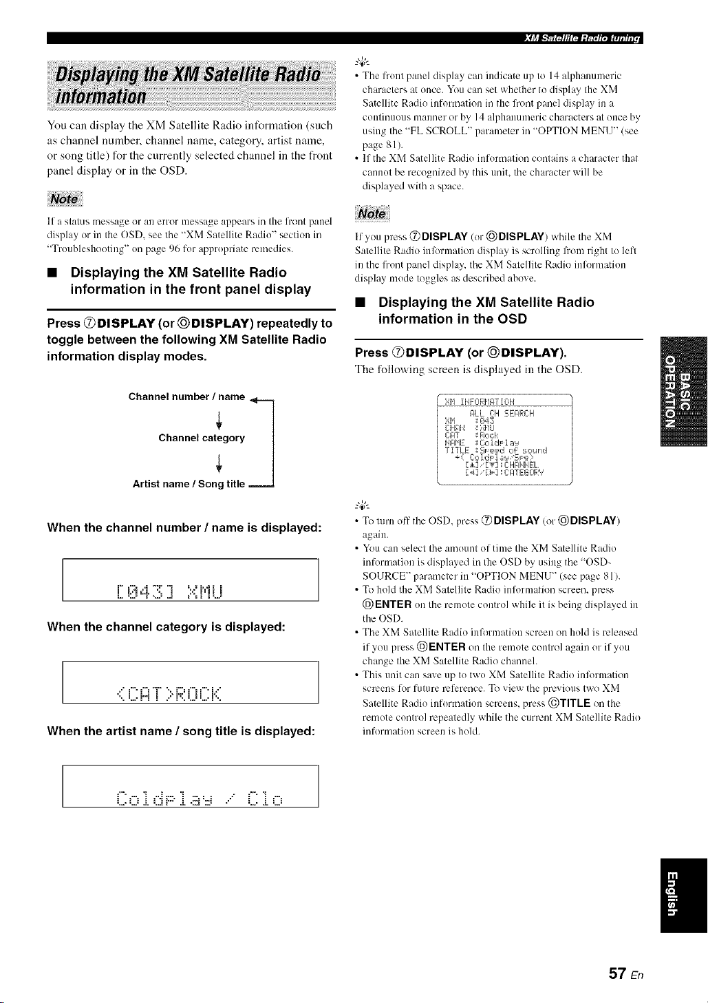
You can display the XM Satellite Radio information (such
as channel nmnber, channel name, category, artist name,
or song title) for the currently selected channel in the front
panel display or in the OSD.
If a stalus message or an error message appears in the lront panel
display or in Ihe OSD, see the "XM Satellite Radii)" section in
"Troubleshooting" on page 96 for appropriate remedies.
• Displaying the XM Satellite Radio
information in the front panel display
Press @DISPLAY (or @DISPLAY) repeatedly to
toggle between the following XM Satellite Radio
information display modes.
Channel number/iame
When the channel number / name is displayed:
r" t'::i...i "T 'i =...=i.=.ii i
L. =L.="T ",,J J ='"=i _=,,.=
When the channel category is displayed:
.:" f" f"_T ":, i:.::'f"i f" i.:"
When the artist name / song title is displayed:
• The front panel display can indicate up to 14 alphalmmeric
characters at once. You can set whether to display the XM
Satellite Radio information in the front par]el display in a
continuous manner or by 14 alphanumeric characters at once by
using the "FL SCROLL" parameter in "OPTION MENU" (see
page 81).
• If the XM Satellite Radio information contains a character that
cannot be recognized by this unit, the character will be
displayed with a space.
If you press @ DISPLAY (or @DISPLAY) while the XM
Satellite Radii) information display is scrolling from right to left
in the front panel display, the XM Satellite Radio inlormation
display mode toggles as described above.
• Displaying the XM Satellite Radio
information in the OSD
Press @DISPLAY (or _)DISPLAY).
The follow,ing screen is displayed in the OSD.
}',1'] II@-0RMgT I0H
#LL C:H EEARCH
};I'1 ; ¢_43
CHAI4 ; ',>41,1LI
ClOT _ Rock
HI31'IE ; Cc,ldF la'_
TITLE _Sl=k=,ed of :_ound
+( C:o IdF 1 _=,'_'SJ:e ?
[_] '[T] 11C:HGIHIqEL
r_/] _r>] : CATEGOR','
• To turn off the OSD, press @ DISPLAY (or @DISPLAY)
again.
• You can select the amount of time the XM Satellite Radio
inlonnation is displayed irathe OSD by using the "OSD-
SOURCE" parameter in "OPTION MENU" (see page 81).
• To hold the XM Satellite Radio inlormation screen, press
@ENTER on the remote control while it is being displayed in
the OSD.
• The XM Satellite Radio inlbrmation screen on hold is released
if you press @ENTER on the remote control again orif you
change the XM Satellite Radio channeh
• This unit can save up to two XM Satellite Radii) inlbrmation
screens lot future reference. To view the previous two XM
Satellite Radio information screens, press @TITLE on the
remote control repeatedly while the current XM Satellite Radio
information screen is hold.
Col. dF::.i ... C i o
I
57 En

Once you have stationed your iPod in a Yamaha iPod universal clock (such as the YDS-10, sold separately) connected to
the DOCK terminal of this unit (see page 23), you can enjoy playback of your iPod using the supplied remote control.
You can also use the Compressed Music Enhancer mode of this unit to improve the sound quality of the compression
artifacts (such as the MP3 format) stored on your iPod (see page 46).
• Only iPod (Click and Wheel), iPod nano. and iPod mini are supported.
• Some features may not be compatible depending on the model or the software version of your iPod.
• For a complete list of the remote control 15ulctions used to control your iPod. see the "iPod" column ill "Controlling other
components" on page 86.
• For a complete list of status messages that appear in the front panel display and ill the OSD. see the "iPod" section in
"Troubleshooting" on page 101.
• Once the connection between your iPod and this unit is complete. "iPod connected" appears ill the front panel display and the DOCK
indicator lights up ill the fi'ont panel display.
• Only the analog audio and video signals of your iPod are input at the DOCK terminal, and the analog audio signals can be output at the
analog AI JDIO O1JT (REC)jacks lor recording.
• Your iPod battery is automatically charged when your iPod is stationed iraa Yamaha iPod universal dock connected to the DOCK
terminal of this unit as long as this unit is turned on. You call also select whether this unit charges the battery of the stationed iPod or
not when this unit is irathe standby mode by selecting the "STANDBY CHARGE" parameter ill "OPTION MENU" (see page 83). The
DOCK indicator turns on while this unit charges Ihe battery of the connected iPod whm/this unit is in the standby mode.
You can control your iPod when "V-AUX" is selected as
the input source. The operations of your iPod can be done
with the aid of the OSD of this unit (menu browse mode)
or without it (simple remote mode).
• Controlling iPod in the simple remote
mode
You can perform the basic operations of your iPod (play,
stop, skip, etc.) using the supplied remote control withont
the aid of the OSD of this nnit.
• You can view the photos or vide() clips stored on your iPod.
• Operations call be also done with the controls on your iPod.
• Controlling iPod in the menu browse
mode
You can perform the advanced operations of your iPod
using the supplied remote control with the aid of the OSD
of this unit. You can browse the songs stored on yonr iPod
in the OSD. Further, you can change or adjust settings for
your iPod to suit your personal preferences.
"4:--
• The name of the song being played also appears in the front
panel display according to the "FL SCROLL" parameter ill
"OPTION MENU" (see page 81).
• You can select the amount of time the iPod menu and play
information is displayed in the OSD by using the "OSD-
SOURCE" in "OPTION MENU" (see page 81).
• Operations cannot be done with the controls on your iPod.
• The YAMAHA logo appears ill the display window of your
iPod.
• There are some characters that cannot be displayed ill the front
panel display or ill the OSD of this unit. Those characters are
replaced with underscores "".
• The "Settings" parameters can be changed or atliusted only in
the OSD. Press ENTER on the remote control to toggle between
the "Settings" parameter settings.
• You cannot browse the photos or video clips stored on your
iPod in the OSD. Use the simple remote mode to enjoy
watching the photos or video clips stored on your iPod.
58 En
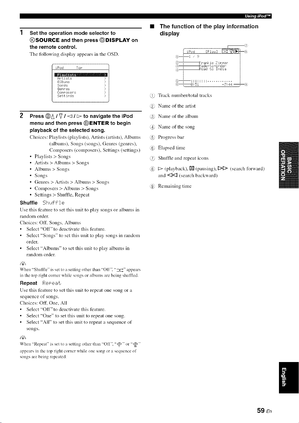
Set the operation mode selector to
@SOURCE and then press @DISPLAY on
the remote control.
The t_llowing display appears in the OSD.
iPod TOF
Rr {i:_ts
R ik,uI,_:-=
L-Op_F O:_ _-2,1":==
Sett ing_
2 Press @A / V / <:1 / _> to navigate the iPod
menu and then press (_ENTER to begin
playback of the selected song.
Choices: Playlists (playlists), Artists (artists), Albums
(albums), Songs (songs), Genres (genres),
Composers (composers), Settings (settings)
Playlists > Songs
Artists > Albums > Songs
Albums > Songs
Songs
Genres > Artists > Albums > Songs
Composers > Albums > Songs
Settings > Shuffle, Repeat
Shuffle :!!;i"iu'F"f:'].e
Use this feature to set this tlnit to play songs or albums in
random order.
Choices: Off. Songs, Albums
• Select "Off"to deactivate this feature.
• Select "Songs" to set this unit to play songs in random
order.
• Select "Albums" to set this unit to play albums in
random order.
"4_':
When "Shuffle" is set to a setting uther than "Off". "7_r_" appears
in the top right corner while sungs or albums are being shullled.
Repeat i:;i:e F:e.i#:,
Use this feature to set this unit to repeat one song or a
sequence of songs.
Choices: Off. One, All
• Select "Off"to deactivate this feature.
• Select "One" to set this unit to repeat one song.
• Select "All" to set this unit to repeat a sequence of
songs.
When "Repeat" is set to a setting other than "()ff'_ "@" or "_"
appears in the top right corner while une song or a sequence uf
songs are being repeated.
q--/lipii'd;t';llr
The function of the play information
display
@ Track number/total tracks
@ Name of the artist
@ Name of the album
@ Name of the song
@ Progress bar
@ Elapsed time
@ Shuffle and repeat icons
@ t::> (playback), 00 (pausing), 12>[:> (search forward)
and <:1<3 (search backward)
@ Remaining time
59 En

Recording adjustments and other operations are performed from the recording components. Refer to the operating
instructions for those components.
Caution
The DTS signal is a digital bitstream. Attempting to digitally record the DTS bitstream will result in noise being
recorded. Theret_re, if you want to use this unit to record sources encoded in DTS, the following considerations and
adjustments need to be made. To play DTS-encoded DVDs and CDs (when using a digital audio connection) on your
DTS-compatible player, follow its operating instructions to make a setting so that the analog signal will be output
from the player.
• When this unit is set to the standby mode, you cannot record between other components connected to this unit.
• TONE CONTROL (see page 48) and VOLUME settings, the speaker level (see page 74) and the sound field programs (see page 42)
do not affect recorded materiah
• The source connected to the MULTI CH INPUT jacks of this unit cannot be recorded.
• The XM Satellite Radio signals cannot be output at the AUDIO OUT (REC) jacks.
• Digital signals input at the DIGITAL INPUT jacks are not output at the analog AUDIO OUT (REC).jacks li)r recording. Likewise,
analog signals input at the AUDIO IN jacks are not output at the DIGITAL OUTPUT jack. Therefore, if your source component is
connected to provide only digital or analog signals, you can only record digital or analog signals.
• A give)) input source is not output on the same OUT (REC) channeh
• S-video and composite vide() signals pass independently through the vide() circuits of this unit. Therefure, when recording or dubbing
video signals input from a video source component that provides only an S-video or a composite video signal, you cat) only record an
S-video or a composite video signal on your VCR.
• The analog audio signals input at the DOCK terminal cat) be output at the analog AUDIO OUT (REC) jacks for recording.
• Check the copyright laws in your country to record l?om CDs, radio, etc. Recording of copyrighted material may infringe copyright
l:_ws.
Do a test recording before you start an actual recording.
If you play back a video source that uses scrambled or encoded signals to prevent it from being dubbed the picture
itself may be disturbed due to those signals.
1
2
Turn on all the connected components.
Rotate the @INPUT selector (or press one
of the input selector buttons (@)) to select
the source component you want to record
from.
3 Start playback on the selected source
component or select a broadcast station.
4 Start recording on the recording component.
60 En
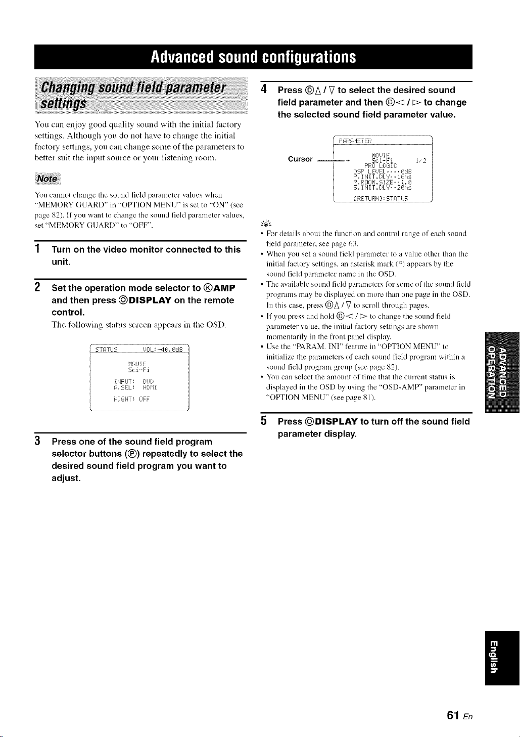
You can enjoy good quality sound with the initial fi_ctory
settings. Although you do not have to change the initial
factory settings, you can change some of the parameters to
better suit the input source or your listening room.
You cannot change the sound field parameter values when
"MEMORY GUARD" in "OPTION MENU" is set tu "ON" (see
page 82). If you want to change the suund field parameter values,
set "MEMORY GUARD" to "OFF".
1 Turn on the video monitor connected to this
unit.
2 Set the operation mode selector to @AMP
and then press _DISPLAY on the remote
control.
The following status screen appears in the OSD.
L--TPTLJS OOL_ .-40_ OdE:
HOUI E
Sci-Fi
ilIpLI]: DUD
I:1, EEL:= HDI'Ii
HIGHT_ OFF
3
Press one of the sound field program
selector buttons (®) repeatedly to select the
desired sound field program you want to
adjust.
4 Press @A / V to select the desired sound
field parameter and then @< / E> to change
the selected sound field parameter value.
Cursor
I/2
F'RO LOGIC
DSF' LEUEL. ,,..OdG
F',iHIT. I)L%, iGm:_
F',ROOII,,SiZE_, i, O
S,,I lqiT,,DLV,, 20ms
II_:ETLJI_:Iq]_STF4TUS
• Fordetails abuut the function and control range uf each sound
field parameter, see page 63.
• When you set a sound field parameter to a value other than the
initial factury settings, an asterisk mark (% appears by the
sound field parmneter name in the OSD.
• The available suund field parameters lbr some of the suund field
programs may be displayed on mute than une page in the OSD.
lu this case, press @A / V to scroll through pages.
• If you press and hold @<1 / E> to change the sound field
parameter value, the initial factory settings are shown
momentarily in the front panel display.
• Use the "PARAM. INI" lcature in "OPTION MENU" tu
initialize the parameters of each sound field program within a
sound field program group (see page 82).
• You can select the amuunt uf time that the current status is
displayed in the OSD by using the "OSD-AMP" parameter in
"OPTION MENU" (see page 81).
5 Press _DISPLAY to turn off the sound field
parameter display.
I
61 En

• Basic configuration of sound field
programs
_.,4_,.
To oh:rage sound fiehl p:lrameter settings, see page 61 lor details.
Each sound field program has some parameters defining
the characteristics of the program. To customize the
selected sound field program, adjust "DSP LEVEL" and/
or "DIALG.LIFT" first, and then try other parameters.
Adjusting the effect sound level of the sound
field programs (DSP LEVEL)
Sound field programs add effect sounds (DSP effect
sounds) to the original source sound to create sound field
in the listening room. Use the "DSP LEVEL" parameter to
adjust the level of the effect sounds.
Adjusting the vertical dialogue position
(DIALG.LIFT)
Use this feature to adjust the vertical position of the
dialogues in movies. The ideal position of the dialogues is
at the center of the video monitor screen.
ideal
dialogue
position.
If the dialogues are heard at the lower position of the video
monitor screen, increase the value of "DIALG.LIFT".
@
The DSP effect
sound level is low.
The DSP effect sound
level is high.
Adjust "DSP LEVEL" asfollows:
Increase the value of "DSP LEVEL" when
• The effect sound of the selected sound field
program is too weak.
• You cannot recognize any difference between the
sound field programs.
Decrease the value of "DSP LEVEL" when
• The sound is vague.
• You feel that the additional sound effect is
excessive.
Control range: 6 dB to +3 dB
Move up to the ideal dialogue position.
Choices: O, 1, 2, 3, 4, 5
"0" (initial setting) is the lowest position, and "5" is the
highest position.
• "DIALG.LIFT" is only available only "EXTRA SP ASSIGN"
is set to "PRESENCE" (see page 72).
• You cannot move the dialogue position down lrom the initial
dialogue position.
62 En

• Sound field parameters for the advanced configurations
Use tile following sound field parameters to custcmfize sound field programs in detail.
-#.
To change sound field parameler sellings, see page 61 lor details.
Ti..iT"i" P',i LJ
.LH.L _ =r L..'L...
i:::'.. Ti'._TT ,. i":_i_.,._
_ii? _i_i_i_i_'_i_ i_,_i _i
....,:= ._.H.L I _=k=q..., i
_?_;ii_ _i_i_i_i _ i_,_i _i
....'L.' .LH .t. =: L.'L. i
Initial delay. Presence. surround, and surround back sound field initial delay. Changes the
apparent distance l)'om the source sound by atljustiug the delay between the direct sound and the
first reflection healxl by the listener. The smaller the value, the closer the sound soul_e seems to
the listener.
?4;'-
When you adjust the initial delay parameters, \x,realso reconmaend a;ljusting the corresponding
roonl size parameters likewise. This atljustn/eut is especially effective for the CINEMA DSP
progran/s.
Control range: 1 Io 99 ms (INIT.DLY and P.INIT.DLY)
1to 49 ms (S.INIT.DLY and SB INI.DLY)
Time
Delay
,0
Reflection face
Source SOUlld
i,/
In refleclions
i
Time
Delay
9 "
2
Time
Delay
Small value= I ms Largevalue= 99 ms
63 En

_ii_iii_ iiii_i_i_i i_i _iii_ _i_"_ ill:_
[ Ti..[F:'Hi:::'c:;,::_
':_..i T1.ji:::'H F:'::_':::;
,::=i=, i Ti ii='i..ii::,='4:'
Room size. Presence. surround, and surround back room size. A@lsts the apparent size of the
surround sound field. The larger the value, the larger the surround sound field becomes. As the
som]d is repeatedly reflected around a room. the larger the hall is. the longer the time between
the original reflected sound and the subsequent reflections. By controlling the time between the
reflected sounds, you can change the apparent size of the virtual vemm. Changing this parameter
from one to two doubles the apparent length of the room.
-"4;'-
When you a@lst the room size parameters, we also recommend adjusting the corresponding
inifial delay parameters likewise. This adjustment is especially effective Dr the CINEMA DSP
programs.
Control range: 0.1 Io 2.0
Source gOuI)d
Time Time Time
Sound source
_), i j j, i j
Small vahle =/).l Large value = 2.0
Liveness. Surround and surround back sound field liveness. Atliusts the reflecfivity of the virtual
walls in the hall by changing the rate at which the early reflections decay. The early reflections of
a sound source decay much faster in a room with acoustically absorbent wall surfaces than in one
which has highly reflective surl:.ces. A room with acoustically absorbent surl_ces is relcrred to
as "dead". while a room with highly reflective surfaces is referred to as "live". This parameter
lets you at{just the early reflection decay rate and thus the "liveness" of the room.
Control range: 0 Io 10
aa ead
Time
I Small reflecled
I sound
Small value = 0
Source sound
Time Time
Large value = 10
64 En

iD_:Fi i "7 T _,'ii::?
Reverberation time. Attiusts the amount of time taken lor the dense, subsequent reverberation
sound to decay by 60 dB at I kHz. This changes the apparent size of the acoustic environmmlt
over all extremely wide range. Set a longer reverberation time for "dead" sources and listening
room environments, and a shorter time lot "live" sources and listening room environments.
Control range: 1.0 to 5.0 s
i:?i:::'i.j.. f')i:::'il:'ac)
Reverberation Source sound Reverberalion
_i II.... Early reflectit ns
60 dB
Bi,,
I_l I d
REV.T|ME REV.TIMEREV.TIME
SOt l( S )t rce
! Short
-
÷
Small value = 1.0 s Large vahle = 5.0 s
Reverberation delay. Adjusts the lime difference between rice heginning of the direcl sound and
lice beginning of lice reverberation sound. The larger the value, the later Ihe reverberation sound
begins. A later reverberation sound makes you feel as if you are ill a larger acoustic environment.
Control range: 0 Io 250 ms,
"7j [ Source soun(.]
k I
(dB)
60 dB
Time
L .L
REV.DELAY REV.TIME
iDi2'i i i i:::'i ii:::<i
l'><l,,,,'v< =: i,,,,i,,,,'.,,'i,,,,i, Reverberation leveh Ac/jusls the volume of the reverberation sound. The larger the value, the
stronger tile reverberation becomes.
Control range: 0 to 100%
Source Sotlnd
_EVEL Time
65 En

2,:::.1_ :!!:;i:e i..e o
i", T iD i:::'l"' "i"
L..' .I. I'><I....',,,, I
7',:::.i_ :!!:;Le r.,i?o
i"'"i" i i:::'i ii:::'i
,.... I L...L...'...<I....I
,:::'i i i:::'i ii:::'i
....'L... I....L...'..*<L. I
,:::'i:::, i i:::'i ii:::'i
,:::'i:::, i i:::'i ii:::'i
....'L.' L.. I....'..*<L. I ....
i:::,i i i:::'i ii:::'i
I L... L...I....'..*<L.I ....
i:::,i:::, i i:::'i ii:::'i
I I'.. L..L...'./L**I
'.? r'.P'i I" i."d"i .::M._u".g:, i._,
7,:::.hEi ,h?.,i>:::ei._.
2-channel stere() direct. Bypasses Ihe decoders and the DSP processors of this mill for pure hi-fi
stere() sound v,'hen playing 2-channel analog sources.
Choices: AUTO,OFF
• Select "AUTO" to bypass the decoders, the DSP processors and the tone control circuitry only
when "BASS" and "TREBLE" are set to 0 dB (see page 48).
• Select "OFF" not to bypass the decoders, the DSP processors and the tone control circuitry
when "BASS" and "TREBLE" are set to 0 dB.
• When multi-chamlel signals (Dolby Digital and DTS) are input, they are downmixed to 2
channels and output lhom the front lell and right speakers.
• The low-frequency signals input lhom the front left and right speakers are redirected to the
subwoofcr in the lollovdng cases:
"LFE/BASS OUT" is set to "BOTH" (see page 72).
"FRONT SP" is set to "SMALL" (see page 73) and "LFE/BASS OUT" is set to "SWFR"
(see page 72).
7-chamml stereo center, surround lelt. surround right, surround back. presence left and presence
right levels. Attjusts the volume level of each channel in the %channel stere() mode. The
available parameters difler depending on the setting of the speakers.
Control range: 0 to I OOC/<
2-chamml and 7-channel Cmnpressed Music Enhancer effect level The lfigh-frequmlcy signals
of some sources may be emphasized too nmch. In Ibis case. set the eflecl level to "LOW".
Choices: HIGH, LOW
• Select "HIGH" lor a high elfect leveh
• Select "LOW' for a low effect level
• Selecting decoders used with sound
field programs (Decoder Type)
Use this feature to select the desired decoder used with
MOVIE sound field programs (except "Mono Movie").
See page 45 for details about MOVIE sound fiekt
program.
Available decoders
i:::ii_::il"l i t"11'::<< Ti"' Dolby Pm Logic processing lor any
i l'..,.J L...'..."..I.L'....
soLirces
Dolby Pro Logic IIx (or Dolby Pro
i:::,iT 'r.. i"i,",_..,'i ,::a Logic lI) processing lor movie
i:::'i'[ T ?"i,",_.>_'i ,::a sources. The Pro Logic llx decoder
........................ is not available when "SB L/R SP"
is set to "NONE" (see page 73).
) SS _r • '
l"4eO',',6 1:'i i.",,:::,iv_.:::, DTS pr( ce ine fol movie sources
• Selecting decoders for 2-channel
sources (surround decode mode)
Use this feature to play back sources with selected
decoders. You can play back 2-channel sources on multi-
channels.
Set the operation mode selector to @AMP and
then press (_SUR. DECODE repeatedly on the
remote control to select the desired surround
decoder.
You can select from the following modes depending on the
type of source you are playing and your personal
preference.
-#-
Youcan change the decoder parameter settings. Press DISPLAY
and then (_)_ / V repeatedly on the remote control to select the
desired decoder parameter. You can change the value of the
selected parameter by pressing (_)<d / [::>repeatedly on the
rmnote control.
66 En
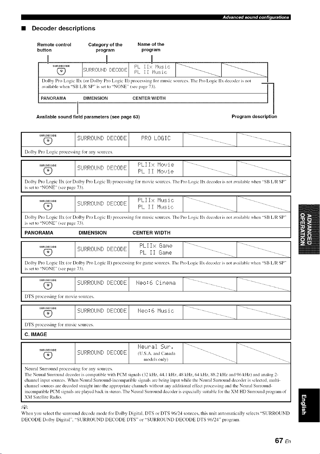
• Decoder descriptions
Remote control Category of the Name of the
button program program
I I !
sources. The Pro Logic |lx decoder is nol
_"°_°°°_(_ .>",,_'-'1-"....._''_' [:,EK:OF)E F:'L_"L"'[_[i >:i,,.M:,_i.i c:,_'_.'_'::.:/..... __ __
Dolhy Pro Logic IIx (or Dolby Pro Logic I1) processing for music
available when "SB L_ SP" is set Io "NONE" (see page 73). ] ]
'1
PANORAMA DIMENSION CENTER WIDTH
i
Available sound field parameters (see page 63) Program description
Dolby Pro Logic processing for any sources.
..........Q_) :!!;i...ll',::l',::l...ll...ll".ll..:,i;'ECO[;' F::'L.ii N,:::,,...,:i.e
Dolhy Pro Logic Ilx (or Dolby Pro Logic 11)processing lor movie sources. The Pro Logic llx decoder is not available when "SB L/R SP"
is set to "NONE _!see page 73).
1 [ I:::'L.i[ ]i?.::ML.J:_II.:i.,_; J .............. I ...........................
..........Q_) Si...i{:;i:i:;31.)Lii'.i[)[)i!!(_:0[)i!!! i:::'i T T Hi J.:::.i,". ...........
Dolby Pro Logic llx or Dolbv Pro Logic 11)processing for music sources. The Pro Logic llx decoder is nol available when "SB L/R SP"
is set to "NONE _!see page 73).
PANORAMA DIMENSION CENTER WIDTH
i;,EC0[;,E F::'L.i i ::.::(!).ii_i',',iil,-................... -........... _..................
_..o_ooo_ Si...iRF;;31.)i...ibi[) i:::'i T T l'::i.::,i',',,:::,
Dolby Pro Logic Ilx (or Dolby Pro Logic 11)processing liar game sources. The Pro Logic llx decoder is not available when "SB L_ SP"
is set to "NONE _(see page 73).
DTS processing for movie sources.
..........[s,R:,H:c,:cc,1 1.......-_ [--......
DTS processing for music sources.
C. IMAGE
SUB.DECODE ,::."i ii:::,i:::,l"li ii..ir'._ r'.,i::h"._"ff'.,i:::" "_.
Q_) ...."...'_".J".'...'_...'_'JJ..=" _.."J..,.'...'_..."-."J.... !U.S.A. and Canada -_ --_
models only) "_-
Neural Surround processing liw any sources.
The Neural Surround decoder is compatible with PCM signals (32 kHz, 44.1 kHz, 48 kHz, 64 kHz. 88.2 kHz and 96 kHz) and analog 2-
channel input sources. When Neural Surround-incompatible signals are being input while the Neural Surround decoder is selected, multi-
channel sources are decoded straight into the appropriate channels without any additional effect processing and the Neural Surround-
incompatible PCM signals are played back in stereo. The Neural Surround decoder is especially suitable for the XM HD Surround program of
XM Satellite Radio.
When you select the surround decode mode for Dolby Digital. DTS or DTS 96/24 sources, this unil automalically selecls "SURROUND
DECODE Dolby Digital". "S1JRRO1JND DECODE DTS" or "SURROUND DECODE DTS 96124" program.
67 En

Decoder parameter descriptions
F::'F;?.Cl LCl(!!i ]i C ]i ]i ;.: Mi...i!il.:i. c Pro Logic [Ix Music and Pro Logic 1I Music panorama. Sel]ds stereo signals Io the stlrround speakers as
F::'F;I:Cl LCl(!!i ]i C ]i ]i i"ii..4:iil.J. c well as Ihe fronl speakers for a wraparound effect.
r"u ",...,_'..r"u_r"., Choices: OFF, ON
F:i:;b::)LO(!!i:[C :[:[':: M_is:b::.
l°,'l.=::Ul..J...li.::iI L: I .{, I"I_..4:111.:l.,:::.
r',, T i,,'ii;:'i,, i ,:::' T i"li,, i
F:i:;b:::lLO(!!i:[C :[:[':: M_i.,.ii:i.,:::.
i..,ll..,,_l i _11..:_1 = _ _ ]"]i,i,:::.'ll",
i"'i:::'M"i%::'i:::, i.i T r',,"r'i...i
_". T i.,'i_"H':::i:::"
Pro Logic I[x Music and Pro Logic 1I Music dimension. Adjusts the sound field either towards the front
or towards the rear.
Control range: 3 (towards the rear) to +3 (towards the front)
Initial setting: STD (standard)
Pro Logic llx Music and Pro Logic [1Music center width. Moves the center channel output completely
towards the center speaker or towards the front left and right speakers. A larger value moves the center
chmmel output towards the front left and right speakers.
Control range: 0 (center channel sound is output only from the center speaker) to
7 (center cllannel sound is output only from the front left and right speakers)
Initial setting: 3
DTS Neo:6 Music center image. Adjusts the front left and right channel output relative to the center
channel to nlake the center channel more or less dominant as necessary.
Control range: 0.0 to 1.0
lnilial selting: 0.3
68 En
You call use the following parameters ill "SET MENU" to adjust a variety of system settings and customize the way tiffs
unit operates. Change the initial settings (indicated in boM under each parameter) to reflect the needs of your listening
environtnent.
• Auto setup ,....i"r,-,,::=::v,_i:::,
Use this feature to automatically adjust speaker and system parameters (see page 28).
• Manual setup i"il:::li"iUi::IL:!!!;E7[i...ii:::'
Use this feature to manually adjust speaker and system parameters.
Sound menu :[ Sl]i..jl..l[:, M[!!]"4U
Use this menn to manually adjust any speaker settings, alter the quality and tone of the sound output by the system or
compensate for video signal processing delays when using LCD monitors or projectors.
_",'., ,:::'i:::,i:::',"_i...'c'i:::,,:::'_:::'"r Selects tile size of each speaker, tile speakers for low-lYequency signal oulput, tile crossover 72
frequency and tile assignment of tile EXTRA SP lerminal.
...........................................i:::I"?'::_i:::'{:::'lTai.::'i:::'i:;?i l':::'i.Ji:::'i A({iusts Ihe output level of each speaker. 74
,...._"''.,,:::'i:::,.......,__....r"T,:::'"r ,"_i..h".i::r._.....,_ r".,_'_,...._.. Acliusts Ihe distance of each speaker. 75
_....r"..."i...,.:.:,...,r ".q....i::r_"li i¢"_i Ta._:..."2i...r..i:ri1::, A(!iusts Ihe tonal qualily of Ihe center speaker. 75
E>LF'E I....E?.)i!!EI.... Acliusts Ihe output level of Ihe LFE channel for Dolby Digital or DTS signals. 76
li:::'..'%i..='i'%i"lM,"M','il1'H",q i T.I.'....'"` I'.. r"HiD l", H I'::: i::7",%.I ,'.... A(!iusts Ihe dynamic range of Dolby Digital or DTS signals. 76
,..._.."r".,,...,_...'._.,...,_':::" ,"_iJr'.,T_", ....,_...':::'i:::'T_ A(liusts Ihe muting level, audio delay maximum vohlme level and initial vohlme level. 76
L.i ", i..Jr",h'i T <:Ti:::'"r
_..'__...'__._. ....,_...._ Selects the componenl Io play back HDMI audio signals. 77
]i ) [!!_?:','T'[? !!!J...iR ,, Selects the mode of Ihe decoders for the 6. I17. I-channel playback. 77
Input menu ":' .i.i..iiDii-i.. i.,=ii:::.i..iii
Use this meillJ to manually reassign the input/output jacks, select the input mode or rename the input source.
r"l..'l"'% ._..'T..' i",,...,r"l ..., ...., ._.*...l_ 'l li", ,7 ,::7 T i':::i.. i i',=ii:::' i..i "i"II...._'l _ Assigns tile inptll/output jacks of this ullit according to Ihe COlilponenl to be used. 7g
_...,.." a. _ '=_ ,..., = r.a..._ '=r"H _ .... Changes the name of Ihe illput sotlrce. 79
,...._"'.."'...",...,_....,...,_iff"_i i ih'ii:::'H...."ri:::,_r.. Ta.=M_ A(!just s tile otltptll volume of each input source. _0
r'.,".,i".,i:::'_".¢5r'.,i:::'i:::, i.,.i_"d".,i:::' Selecls Ihe input mode for Ihe sources connected Io the DIGITAL INPUT jacks on Ihe rear
panel of this unit.
i:::'',, i.,_iii "r T ,==i..a,:::'ixr"i"
_.....:__,...,_...._ ._. ,...q_ ....,_...._ Sets tile inpul channel numbers and olher parameters of Ihe multi channel inlxlt. 80
69 En
Option menu ":r ,%i;::,"i"'i*,"lMi'di;::'i..iii
Use this menu to manually adjust the optional system parameters.
r"ll"l.." i..='i%a.T....,__:::'i1::,ii...r"ii"0..i] ....,i....'::'ii::'"r'_ Adjusts the brighlness of the display and convel[ s video signals. 81
i:::,".,i.,_i:ri.,.i,",i:::,_.._,':::ii,",i:::,i"., 82
_...,..'__....__,...,_',_ ,.._,...,r"_'.._..= Locks sound field progralll paran/elers and other "SET MENU ' sellings.
*....l"'.."r".',...,l...'¢"liir'., T.I.'...'¢'I....u.... l... I....'....*:::'i::7i i;::'_"' "i"_ Designales tile default audio input jack select setting lk)l Ihe input sources when you lurn on 82
the power of Ihis unil.
r'., "., i2q"d2,1"d',_ 'i' i..i T _2
_...'..'i r".,_'..ml_,, .i.i".,._ Initializes Ihe paralnelers of a group of sound field programs.
i:::'","::=I'=IMi::: ' ":, ,2:'i:::'"i" AdjuslstheZone2paramelers. g2
i:::' ", :.iM i::)¢"lr'., T ¢"1 *:::'i::F"i"
..',"a _ _'..r".,_...'._.,..., ....,_..._ Displays the currenl receplion level of Ihe XM Salellite Radio signals. 83
12:", i",_%l"'i..",:::'i2'"i" Selects whelher Ibis unit char_es Ihe battelv of Ihe connected iPod or not when this Ullit is ill
_,,,I," L,'*=,,*_,,,'I", *,,,=I,,,,, " _ 83
the slandby mode.
• Signal information C'r,':.':Jr._,",_'J'_..JJ:::,'_,
Use this feature to check audio and video signal information (see page 40).
70 En
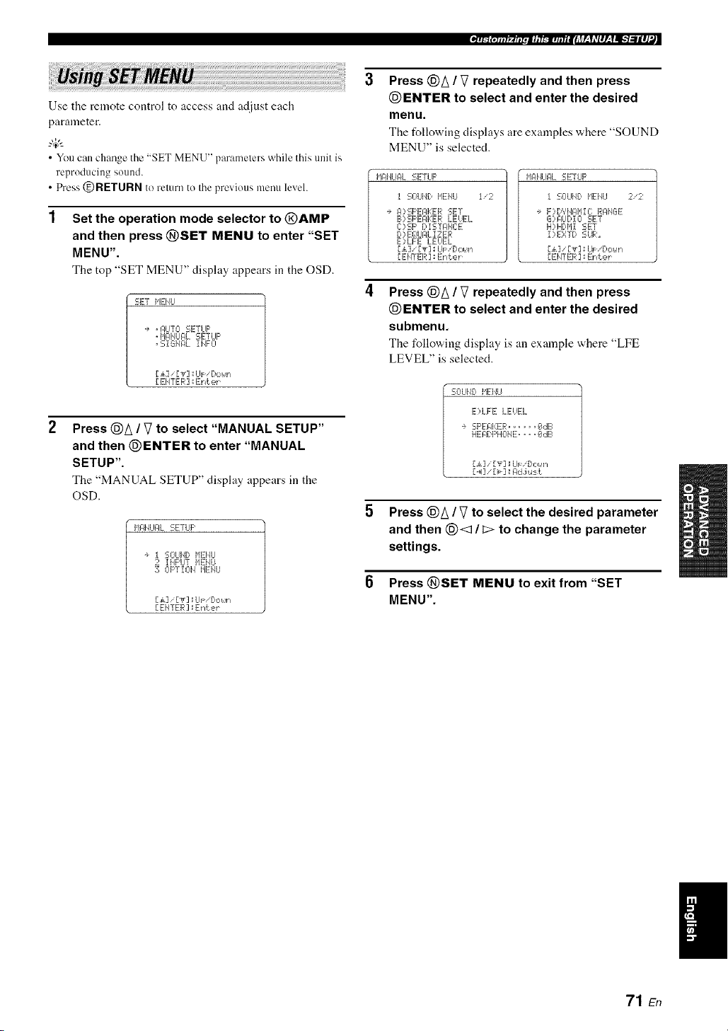
_T_{qllf_.fllpli, l_-m,l,liilJ_r-_1*Vlll-_11-qillll'._
Use the remote control to access and adjust each
parameter.
• You can change the "SET MENU" parameters while this unit is
reproducing sound.
• Press @RETURN to remm to the previous menu level.
Set the operation mode selector to @AMP
and then press @SET MENU to enter "SET
MENU".
The top "SET MENU" display appears in the OSD.
SET MENU
1+ . I:/IJTL-I SETUP
" MANUAL SETUP
" SiGI/AL IIqFO
[,_k] ['_r] _UF 'Do_,,'l
[ EHTER ] _Eniek
2
Press @A / V to select "MANUAL SETUP"
and then @ENTER to enter "MANUAL
SETUP".
The "MANUAL SETUP" display appears in the
OSD.
II_IqLIALSETLIP
÷ I SOUI,41:,HEHLI
2 IMI:'LITIqENU
30I:'TIOI_ HEMU
[£] /[T] _UF!Dot,!n
[EHTER] _Enter
Press @A / V repeatedly and then press
@ENTER to select and enter the desired
menu.
The following displays are examples where "SOUND
MENU" is selected.
HAI'IUAL SETLIF'
I SOLIND HEI,IU I/2
÷ I:I::,SI-_EPI:EI_ISET
B) SI-_EFIKEI;ILEUEL
C)SF' I;,iSTPI'E:E
D::,Eg!UI:JLI ZER
E:,LFE LEUEL
[£] [Y]_UF 'Do_,'n
[EHTER ] _Enter
MAI,ILIALSETLIF'
1 SOLIND MENU 2/2
÷ F)D',IHI:]IqlC RAMGE
G)pLIDIO SET
H)iHDIdl SET
I)EXTD SUR_
[£] / [Y] _UF,'Do_,'n
[EIITER] _IEnter
Press @A / V repeatedly and then press
@ENTER to select and enter the desired
submenu.
The following display is an example where "LFE
LEVEL" is selected.
SO LIIE:,I'IEI_U
E)LFE LEUEL
÷ SP EFII:::ER ...... _dl-I
HEADF'HCIIE .... _#!dB
[i] ["_]_IiJF [:'OI,qn
[ _I] [_] _I:ldJ,.l:-=k
Press @A / V to select the desired parameter
and then (_< / _> to change the parameter
settings.
Press @SET MENU to exit from "SET
MENU".
I
71 En

ILT_ _.1. t _ u r•iCEt _ ,u n EIJTJLqLq#L'YI_-_l#J:L
Use this feature to manually adjust speaker settings or
compensate for video signal processing delays when using
LCD monitors or projectors. Most of the SOUND MENU
parameters are set automatically when you run AUTO
SETUP (see page 28).
I,Jg41qLIF4L SETUP
I SOUI_I) I,tEl_tl I'2
+ I:I?SF'EAKER SET
B)SF'EPKER kEHI_:L
C)SF' Di STPHCE
D )EQLIFILIZER
E)KFE LEUEL
[ ak] '[',_'] : UF '[lo_._n
[EHTER ] :Enter
MIqI,ILIPL SETLIF'
I SOLII_D MEMU 2/2
÷ F)DYHI:tI'IIC RRMGE
G)PLIDIO SET
H) HDI'il SET
I)EXTD SUR.
[ak] ['_']_UF 'Dc,_,'n
[EHTER ] ::Enter
• Speaker settings """':::i:::'c''"i"c'i:::',:::'_::'"r
Use this feature to manually adjust any speaker settings.
SOLIH) l,tEiqLI
÷ EXTRP SF' PSSIGI4
ZOI4E2 ;FROI4T B
PRESEHC:E HOME
FROI,4T B .....FROHT
F'RI ORi r','_ ........
Z OHIE2 SET
M,:,i. F'v._i ] .=J:,le
Extra speakers assignment EXFRI::i :!!!;[::'gl:!!!;S]:(!!ii"i
Selects the function of the speakers connected to the
EXTRA SP terminals.
Choices: FRONT B, ZONE2, PRESENCE, NONE
When you use the alternative front speaker
system (see page 38)
Select "FRONT B".
When you use the Zone 2 speakers (see
page 90)
Select "ZONE2" to set the function of the speakers to
the Zone 2 speakers.
When you use the presence speakers (see
page 12)
Select "PRESENCE" to set the function of the
speakers to the presence speakers.
When you do not use the EXTRA SP terminals
Select "NONE" to deactivate the EXTRA SP
terminals.
FRONT B speakers setting F'ROiqT" B
The "FRONT B" parameter is awdlable only when you set
"EXTRA SP ASSIGN" to "FRONT B".
Use this feature to select the location of the FRONT B
speakers.
Choices: FRONT, ZONE B
• Select "FRONT" to turn FRONT A and B on or off
when the FRONT B speakers are set in the main room.
• Select "ZONE B" if the FRONT B speakers are set in
another room. If FRONT A is turned off and FRONT B
is turned on, all the speakers including the subwoofer
in the main room are nmted and this unit outputs sound
at the FRONT B terminals only.
• If you connect headphones to tire PHONES jack ofthis uniL the
sound is output fi'om both the headphones and tire EXTRA SP
lerminals when "FRONT B" is set to "ZONE B".
• If a DSP program is selected when "FRONT B" is set to
"ZONE B". Ihis unit automatically enters tile Virtual CINEMA
DSP mode (see page 46).
Presence/Surround back channel priority
i:)i:::, T i"_i::) T "i" L J
Tire "PRIORITY" parameter is available only when you
set "EXTRA SP ASSIGN" to "PRESENCE".
Use this feature to prioritize either the presence or the
surround back speakers when playing sources that contain
surround back channel signals using the CINEMA DSP
sound field programs.
Choices: PRNS, SUN. B
• Select "PRNS" to use the presence speakers even when
surround back channel signals are input. The signals
for the surround back channels will be output from the
surround speakers.
• Select "SUR. B" to use the surround back speakers
w,hen surround back channel signals are detected in a
CINEMA DSP program. The presence channel signals
are output from the front speakers.
• This parameter shares the value with the "EXTRA SP
ASSIGN" parameter it] "AUTO SETUP".
• If you select "ON" it] "BI_AMP" (see page 95), you cannot
select "PRESENCE" or "ZONE2" in "EXTRA SP ASSIGN".
• Aller changing the "EXTRA SP ASSIGN" setting, carry out
"AUTO SETUP" again (See page 28).
72 En
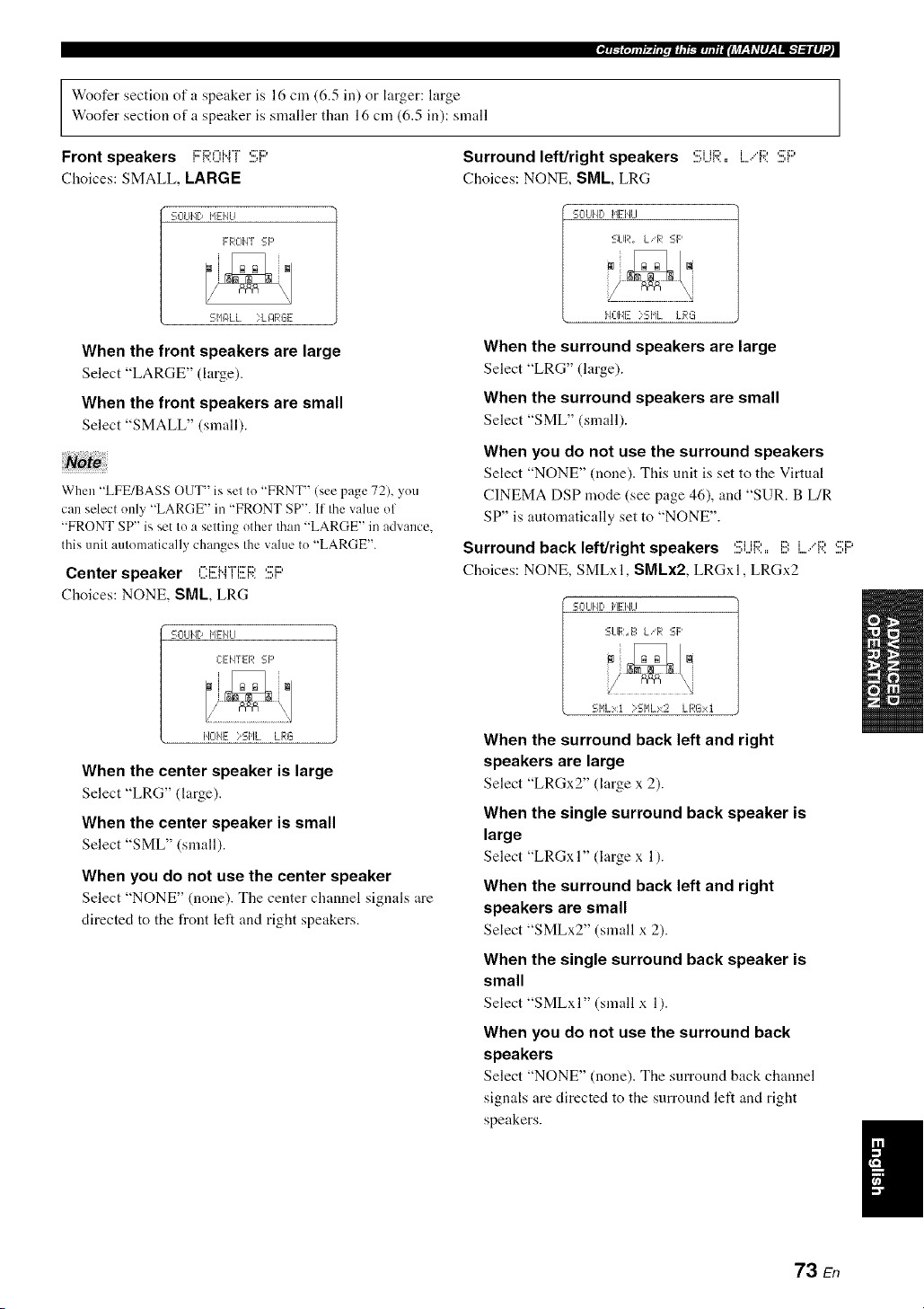
Woofer section of a speaker is 16 cm (6.5 in) or larger: large
Woofer section of a speaker is smaller than 16 cm (6.5 in): small
Front speakers i:::R0i"4[ :!!;i:::'
Choices: SMALL, LARGE
Surround left/right speakers 5i..jR:, L,"F;?.:!!!;i::'
Choices: NONE, SML, LRG
SOUl,It) HEHU
FROIq_ :-F'
SNgILL ?L J:IRGE
When the front speakers are large
Select "LARGE" (large).
When the front speakers are small
Select "SMALL" (small).
No!
When "LFE/BASS OUT" is set to "FRNT" (see page 72), you
can select only "LARGE" in "FRONT SP". If the value of
"FRONT SP" is set to a setting other than "LARGE" in advance.
this unit automatically changes the value to "LARGE".
Center speaker CEMTEF;?.:!!!;i:::'
Choices: NONE, SML, LRG
SOLIHD HEHLI
CEIq_ER SF'
HOHE >SHL LRG
When the center speaker is large
Select "LRG" (large).
When the center speaker is small
Select "SML" (small).
When you do not use the center speaker
Select "NONE" (none). The center channel signals are
directed to the front left and right speakers.
SOUI'IDHID,ILl
SLIR. LiR SF'
lqOIqE?SIqL LRL_
When the surround speakers are large
Select "LRG" (large).
When the surround speakers are small
Select "SML" (small).
When you do not use the surround speakers
Select "NONE" (none). This unit is set to the Virtual
CINEMA DSP mode (see page 46), and "SUR. B L/R
SP" is automatically set to "NONE".
Surround back left/right speakers :!;i...ii:;i:,,i!!:L,"R 5i::'
Choices: NONE, SMLxl, SMLx2, LRGxl, LRGx2
SCILII,4DHEIqLI
SLIR.E=L!R SF'
SI'ILxt )SHLx2 LRGxt
When the surround back left and right
speakers are large
Select "LRGx2" (large x 2).
When the single surround back speaker is
large
Select "LRGxI" (large x 1).
When the surround back left and right
speakers are small
Select "SMLx2" (small x 2).
When the single surround back speaker is
small
Select "SMLxI" (small x 1).
When you do not use the surround back
speakers
Select "NONE" (none). The surround back chmmel
signals are directed to the surround left and right
speakers.
I
73 En

LFE/Bass out i...,F:i!!!;.'[!!:I::ISSOU[
Use this feature to select the speakers that output the LFE
(low-frequency effect) and the low-frequency signals.
Choices: SWFR, FRNT, BOTH
S CILl[i[:,I,IEI,4LI
LFE EIIqSSOLIT
SI,!FRFF:IIT;q_OTH
When a subwoofer is connected to this unit
and you want to get natural bass sound
Select "SWFR" (subv,,oofer). The LFE signals as well
as the low-frequency signals of other speakers set to
"SML" (or "SMALL") are directed to the subwoofer.
When a subwoofer is connected to this unit
and you want to get rich bass sound
Select "BOTH" (both). The low-frequency signals of
any source are output from the subwoofer. The LFE
signals as well as the low-frequency signals of other
speakers set to "SML" (or "SMALL") are directed to
the subwoofer. The low-frequency signals of the front
left and right channels are directed to the front left and
right speakers and the subwoofer regardless of the
"FRONT SP" setting.
When you do not use a subwoofer
Select "FRNT" (front). The LFE signals, the
low-frequency signals of the I_ont left and right
channels, and the low-frequency signals of other
speakers set to "SML" (or "SMALL") are all directed
to the front left and right speakers regardless of the
"FRONT SP" setting.
Bass crossover ,-.J:::,,...,,:::.,:::,.-,_ii::ri:::=
Use this feature to select the crossover frequency of all the
speakers set to "SML" (or "SMALL") or to "NONE" in
"SPEAKER SET" (see page 73). All frequencies below
the selected frequency will be sent to the subwoofer or to
the speakers set to "LRG" (or "LARGE") in "SPEAKER
SET" (see page 73).
Choices: 40Hz, 60Hz, 80Hz, 90Hz, 100Hz, 110Hz,
120Hz, 160Hz, 200Hz
SL-IUIJD HIEI4U
C RClSSCII lEfT:
FREg!,'.. ;_I_lqz
Subwoofer phase Si..jI!!!:WII)ITjF:I!!!F;?.F:II..iASE
Use this feature to svvitch the phase of your sub'a.oofer it"
bass sounds are lacking or unclear.
Choices: NORMAL, REVERSE
S CILIIiE:,I,IEI,_LI
SUEIL,4OCIFERFIHPSE
;q_L-IR['II:ILREUERSE
• Select "NORMAL" if you do not want to reverse the
phase of your subwoofer.
• Select "REVERSE" to reverse the phase of your
subwoofer.
• Speaker level 1!3)SF'i!!EAKEF;;:i....EUEL
Use this feature to manually adjust the output level of each
speaker.
Control range: -10.0 to +10.0 dB
Control step: 0.5 dB
Initial setting: 0.0 dB
SOUHb MEI'ILI
E'?SPEgI<ER LEUEL I/2
- .............................+
÷ FL. .... !!.....
FR ..... ii.....
C:..... I1.....
S[_JlZR..... [[.....
li::ri_. Fronl left speaker
i::'Dv.. Fronl right speaker
,...."= Center speaker
,::7i.ii:::'i:::, Su bwoofcr
'.!!i{.... Surround left speaker
'.!ii?. Surround righl speaker
....,:::_::,i:::,,_...,_... Surround back righl speaker
....,:::'i:::,i,_...,_ Surround back left speaker
1:::4_.... Presence left speaker
""v...... Presence righl speaker
• The available speaker channels differ depending on the setting
of the speakers.
• Instead of"SBL" and "SBR". "SB" is displayed if"SB.L/R SP"
is set to either "SMLxI" or "LRGx 1" (see page 73).
74 En

• Speaker distance C):!!!;F::'[:,iSTANCE
Use this feature to manually adjust the distance of each
speaker and the delay applied to the respective channel.
Ideally, each speaker should be the same distance from the
main listening position. However, this is not possible in
most home situations. Thus, a certain amount of delay
must be applied to the sound from each speaker so that all
sounds will arrive at the listening position at the same
time.
SOUHD IdEHU
C:)SF' DiSTAHCE 1/2
÷ Lll'/l "/ ........ feei
FRI:J'/T L,.. iP. Of_:
FROI4T R... 16, 8ft
CENTER .... 18.8ft
St,JFR...... i@. E_fk
[ak] [.4_.]:IUFiDoNr_
Unit i..jlq]:[
Choices: meters (m), feet (ft)
Initial setting:
[U.S.A. and Canada models]: feet (ft)
[Other modelsl: meters (m)
• Select "meters" to adjust speaker distances in meters.
• Select "feet" to adjust speaker distances in feet.
Speaker distances
Control range: 0.30 to 24.00 m (1.0 to 80.0 ft)
Control step: 0.10 In (0.5 ft)
Initial setting:
FRONT L/FRONT R/CENTER/SWFR/SUR. L/SUR. R/
PRNS L/PRNS R: 3.00 In (10.0 ft)
SB L/SB R: 2.10 In (7.0 ft)
li::'i:::'l"ii"i"J"l',,t..'l'I _ l.i Fron{ left speaker
...........J::rJ:;?nJ".J"[J:;) Flonl right speaker
C:i!!EI".i"T'i!!Ei;;: Cenler speaker
,::2i,ii:::'_:::' Subwoofer
,:7i it:::, i Surround lel_ speaker
....,::Ti,,,,.,{,,,ii:::,,, _',,i:::' Surrotlnd right speaker
....,:::'D,I...,l..i Surround back lel_ speaker
....,:::i:::,,u., _i:::".. Surround back right speaker
i:M:::'i..i':::'v..H....,_i Presence ]el_ speaker
i:::,i:::,i..i,:::'r..H....,_'..[::' Presence right speaker
_"r_jOtllf_.fiipii, l_.l,l,liilJ_r-_Idlll-_lll-'t:lll]'._
• Equalizer [:,::,i!!!(;!LiAL]:;E:i!!!R
Use this feature to select the parametric equalizer or the
graphic equalizer.
Equalizer type select iE(;! 'i;?i:::'l!!!::!!!;E:i...,i!!!C]
Use this feature to select the type of equalizer.
Choices: AUTO PEQ, CENTER GEQ, EQ OFF
SOLIHD I,tEIqLI
D)EG!UPL iZER
Eg_ TYPE SELECT
+ CENTER GEg_
[.&]iU_ ] _C:T 6Eg!
D4],'[_]: Seiect
• Select "AUTO PEQ" to use the parametric equalizer
adjusted in "AUTO SETUP" (see page 28).
• Select "CENTER GEQ" to adjust the built-in 5-
frequency band graphic equalizer so that the tonal
quality of the center speaker matches that of the front
left and right speakers. Press (_)A / _7 to display the
graphic equalizer screen.
• Select "EQ OFF" to deactivate the equalizing feature.
When you carl')' out "AUTO SETUP" in advance (see page 28),
"AUTO PEQ" is automatically selected as the delaull setting.
Test tone "i"i::",::,""i"
i L......, i
SOLIIqD NEHLI
e TES T ::OFF OH
1@Eqqz .. @,.. 8dl-.
3E#3Hz .. dl. " " 8dB
lkHz .. dl... 8rib
3kHz ...[k,. @dB
l@kHz: ,. fib ' " EIdB
[.k] ["_]:=iJi= '[>oun
Use this feature to make adjustments for "CENTER GEQ"
while listening to a test tone.
Choices: OFF, ON
• Select "OFF" to stop test tones and output the currently
selected source component.
• Select "ON" to output test tones from the center and
front left speakers.
• The :rvailable speaker channels differ depending on the setting
of the speakers.
• Instead of "SB L" and "SB R". "SB" is displayed if "SB L/R
SP" is set to either "SMLx I" or "LRGx I" (see page 73).
75 En
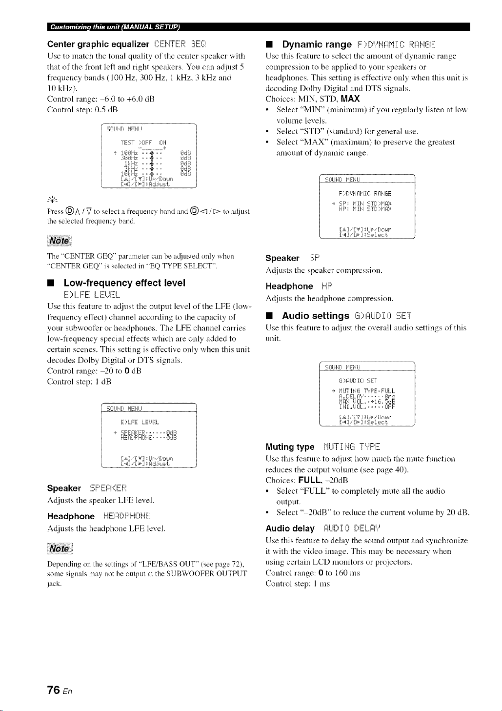
Ee_n/_(.s.t_ur.mcEt_,unEIiTJf-qLqlL'Yl_llJ_
Center graphic equalizer C:EHFER GEQ
Use to match the tonal quality of the center speaker with
that of the front left and right speakers. You can adjust 5
frequency hands (100 Hz, 300 Hz, 1 kHz, 3 kHz and
10 kHz).
Control range: -6.0 to +6.0 dB
Control step: 0.5 dB
'=-ClUIID HEIqLI
TEST :::01:1: J:_ll
- ............. +
+ lOOHz . ..ii... OdE_
3001Hz .. "!I" " " OdB
IkHz ...!1... OdB
:31::iHz: ...!i... OdE_
lOkHz ..... I : OdE1
Fh'ess(_)A / _7to selecl a fi'equencyband and (_) <::1/ L:>to a@mt
Ihe selecled frequency band.
Note
The "CENTER GEQ" parameler can be a@mted only when
"CENTER GEQ" is selecled in "EQ TYPE SELECT".
• Low-frequency effect level
E ::'LF:'E LEVEl
Use this feature to adjust the output level of the LFE (low-
frequency effect) channel according to the capacity of
your subwoofer or headphones. The LFE channel carries
low-frequency special effects which are only added to
certain scenes. This setting is effective only when this unit
decodes Dolby Digital or DTS signals.
Control range: _0 to 0 dB
Control step: 1 dB
SOL¢ID I,IEIqU
E)LFE LEVEL.
+ SF'EIqKER...... OdE
HEI:IDF'HOHE.... OdE
[A] '[',r7 _U_ bc..s,
[ _13'[>3 : gd J u:_t
Speaker ..........................
Adjusts the speaker LFE level.
Headphone iJi::?f..,r'.,i:::,i..Jf",Mix?
Adjusts the headphone LFE level.
Depending on Ihe settings of "LFE/BASS OUT" (see page 72),
some signals may notbe output al the SUBWOOFER OUTPUT
jack.
• Dynamic range F:>E:,YHI::iMiCRI::iNGE
Use this feature to select the amount of dynamic range
compression to be applied to your speakers or
headphones. This setting is effective only when this unit is
decoding Dolby Digital and DTS signals.
Choices: MIN, STD, MAX
• Select "MIN" (minimum) if you regularly listen at low
volume levels.
• Select "STD" (standard) for general use.
• Select "MAX" (maximum) to preserve the greatest
amount of dynamic range.
SOLIIID IqEHLI
F)DYH@11C RI:IHGE
+ SF'_: MIH STD?HF4X
HI:': b11H STI)::HI_',r
[_I] '[>] :Select
Speaker SF::'
Adjusts the speaker compression.
Headphone HF::'
Adjusts the headphone compression.
• Audio settings G::,f::it..ii:::,:[OSET
Use this feature to adjust the overall audio settings of this
unit.
SOUI'4D lql:-I4U
G )I:IUDIO SET
+ HUTIHG "TYF'E.FULL.
I:1. OELI:I', '_ ..... _,P/::-
1,1t:1_iUEII_.. +I L:,.5dB
1141.UOL.. .... OFF
[,,_.]'['_"] ::UF 'l)ot.!n
['<] '[_'] :Selec[
Muting type Mi i"f ' T Me::: "i%Ji:::,i:::
Use this feature to adjust how much the nmte function
reduces the output vohnne (see page 40).
Choices: FUll,-20dB
• Select "FULL" to completely mute all the audio
output.
• Select "-20dB" to reduce the current volume by 20 dB.
i"li ii",l i i'_1 i",liiii'i i"li,,i
Audio delay ,...,,...,,.................,....,....,....,,
Use this feature to delay the sound output and synchronize
it with the video image. This may be necessary when
using certain LCD monitors or proiectors.
Control range: 0 to 160 ms
Control step: 1 ms
76 En

Maximum volume i'J@:: i K)J......
Use this feature to set tile maxinmn] "volume level in tile
main zone. This feature is usefid to avoid the unexpected
loud sound by mistake. For example, the original volume
range is 16.5 dB to -80.0 dB. However, when "MAX
VOL." is set to -5.0 dB, the vohnne range becomes
-5.0 dB to -80.0 dB.
Control range: 16.5 dB, 15.0 dB to 30.0 dB
Control step: 5.0 dB
• When this unit is ill the auto setup procedure, the volume level
is automatically set to 0 dB regardless ol Ilaecurrenl "]',,.'lAX
VOL.' setting.
• The "MAX VOL." setting takes priorily over Ihe "Inilial
Volume" setling. For example, il "INI VOL." is sel Io 20.0 dB
and "MAX VOL" is sel to 30.0 dB. the volume level is
automatically set to 30.0 dB when you turn on the power of
flais unit nexl time.
• Use "MAX VOL." in "ZONE2 SET" Io set Ihe initial volume
level in Zone 2 (see page 83).
initial volume rM'r i il",i
.L I 'i .t. %"_...'L.,,=
Use this feature to set the volume level of the main zone
when the power of this unit is turned on.
Choices: Oft =,-80.0 dB to +16.5 dB
Control step: 0.5 dB
Note,,
• The "MAX VOL." setting takes priority over the "INI VOL."
setting.
• Use "INI VOL." ill "ZONE2 SET" to set the initial volume level
in Zone 2 (see page 83).
• HDMI setting u,,ur,h,r ,:::,::r
Use this feature to select the component to play back
HDMI audio signals.
SOUHD I'lEIqU
H)HDHI SET
SLIpF'ORT I:ILIDI 0_I
RX.-UE,61
[4] _[>] _:Eeiect
[ ENTER ] _Return
Support audio :!!!;i...iF::'F:'Cff;UFl:ii..jl:::,]:(?
Use this feature to select whether to play back HDMI andio
signals on this unit or on another HDMI component connected
to the HDMI OUT.jack on the rear panel of this nnit.
Choices: RX-V661, OTHER
• Select "RX-V661" to play back HDMI audio signals
on this unit. The HDMI audio signals input at the
HDMI IN jacks of this unit are not output to the HDMI
component connected to the HDMI OUT jack on the
rear panel of this unit.
• Select "OTHER" to play back HDMI audio signals on
another HDMI component connected to the HDMI
OUT jack.
_T_(,illf_.fll_,ii, l_'=,t,liilJ_r-'fdlll-'fll_'t=llll'._
Tile HDMI video signals input at the HDMI IN I or HDMI IN 2jack
of Ihis unit are always outpul al the HDMI OUT jack of Ihis unit.
• Extended surround decoders
T :=i:::=.:.:FTT:_':::;iii:;?,.
Use this feature to enjoy 6.1/7. l-channel playback for
multi-channel sources using the Dolby Pro Logic Ilx,
Dolby Digital EX or DTS-ES decoders by using the
connected surround back speakers.
SOLIND 1,1EHLI
I)EXTD SUR,,
÷ HODE ........ I:ILI_0
[4]' [>] :Select
Mode MOC'F'
Use this feature to select the mode of the decoder driving.
Choices: AUTO, ON, OFF
• Select "AUTO" to activate the optimum decoder to
play back the signal in 6.1/7.1 channels when a signal
flag that can be recognized by this unit is input.
• Select "ON" to play back multi-channel sources using
the selected decoder type in "TYPE".
• Select "OFF" not to use the decoders to create 6.1/7.1
channels.
Decoder type ,.i..i..ii:::,i:::lII I,
SOUH) NENLI
i)EXTD SUR,,
+ NODE .......... 01'4
T','F'E... F'L TL:d'lo,Jie
[,,k] [',r]aL]_: D,:,_,q-*
- 7 -- *
Use this feature to select the decoders used to play back
multi-channel sources when you select "ON" in "MODE".
Choices: PLIIxMovie, PLllxMusic, EX/ES, EX
• Select "PLIIxMovie" to play back Dolby Digital or
DTS signals in 7.1 channels using the Pro Logic lIx
movie decoder.
• Select "PLIIx Music" to play back Dolby Digital or
DTS signals in 6.1/7.1 channels using the Pro Logic IIx
music decoder.
• Select "EX/ES" to play back Dolby Digital or DTS
signals in 6.1/7.1 channels using the Dolby Digital EX
or DTS-ES decoder.
• Select "EX" to play back Dolby Digital or DTS signals
in 6.1/7.1 channels using the Dolby Digital EX
decoder.
I
77 En

Use this feature to activate the desired decoder manually when
this unit caunot detect the signal flag encoded to the input sources
correctly.
• The available decoders vary depending on the setting of the
speakers and the input sources.
• 6.117. l-channel playback is not possible in the lollowing cases:
when "SUR. L/R SP" (see page 73) or "SUR. B L/R SP" (see
page 73) is set to "NONE".
when the component connected to the MULTI CH INPUT
jacks is being played.
when the source being played does not contain surround leR
and right channel signals.
when a Dolby Digital KARAOKE source is being played.
when this unit is in the stereo playback, Compressed Music
Enhancer (see page 46) or Pure Direct (see page 48) mode.
when "BI-AMP" is set to "ON" (see page 95).
• When this unit is turned off. this setting will be reset to
"AUTO".
Use this menu to reassign the input/output jacks, select the
input mode or rename the input source.
MgNUF4L SETUP
2 INPUT MEHU
÷ Iq)I '0 PSSIGIqMEIqT
B) i HF'UT REHglHE
C) OOL LIHE "rR IIq
D)DECODER MODE
E)HLILTI OH SET
L,_,]/["_]::LIFiDo_m
[ EHTER ]:Enter
• Input/output assignment
l::i::,:i:..'0 ASSi 8i@iiEi"iT
Use this feature to assign the input/output jacks according
to the component to be used if the initial settings of this
unit do not correspond to your needs. Change the
following parameters to reassign the respective jacks and
effectively connect more components.
Once the input/output jacks are reassigned, you can select
the corresponding component by using the INPUT
selector on the front panel (or the input selector buttons on
the remote control).
-#-
Theinput source name in parentheses indicates the deNult
assigned input source.
For COMPONENT VIDEO jacks A, B and C
Ci"il:::'M"F-U :i:MF:q...ri"
Choices: IAI DVD, I)TV/CBL V-AUX,I)VR, VCR
[B] DVD, DTV/CBL V-AUX, DVR, VCR
[C] DVD, DTV/CBL, V-AUX, DVR, VCR
INPUT MEIqLI
C:III-_i,IT.-iJ IIqpLI_
+ [1:1] ..... DUD
( gIUBI :'
[ B ] ..... DTH C:BL
(DTU 'EBL )
[O] ..... DUR
( DOR )
78 En

For OPTICAL OUTPUT jack 1
i=_:::,"i " T ¢"=_"fi _"li r'F
Choices: (1) PHONO, CD, MD/CD-R, DVD, DTV/CBL,
V-AUX, VCR, DVR
INPUT HEHLI
OF'T IC:PL OUT
•_ <I::, ..... HD C:[_-R
<Hb!C:D-R )
_(qllf_.[ll[,ii, l_-m,miilJ_V-_f*Vlll-_fllg't_llll'._
For HDMI IN jacks 1 and 2 ,, ,,,.i Jr,hi r ,.,_ri'_
Choices: [INI] DVD, DTV/CBL, V-AUX, DVR, VCR
[IN2] DVD, DTV/CBL, V-AUX, DVR, VCR
iHPLI_ HEHLI
HDHi IH
÷ [IIU]... DUD
< DVD ?
[ I H2 ]... DTU. L-:E'L
(DTi 'L-,BL )
• You cannot select a specific item more than once lbr the same
lype of jack.
• When you connect a component Io both the DIGITAL INPUT
(COAXIAL) and DIGITAL INPUT (OPTICAL)jacks, priority
is given Io the signals inpul at the DIGITAL INPUT
((?()AXIAL) jack.
For OPTICAL INPUT jacks 2, 3 and 4
i=_=, "F T {"' {"H TM
Choices: (2) PHONO, CD, MD/CD-R, DVD, DTV/CBL,
DVR, VCR
(3) PHONO, CD, MD/CD-R, DVD, DTV/CBL,
DVR, VCR
(4) PHONO, CD, MD/CD-R, DVD, DTV/CBL,
DVR, VCR
iHPLI7 HEIfiU
OPT iCIqL ilq
•_ <:2) ..... HI) CI:,-R
,:HI! _C:D-R )
(3) ..... Dub
,: DUD ?
<4 ? ..... DTU/CBL
([,TU 'L-:BL)
For COAXIAL INPUT jacks 5 and 6 COAX i F4L ]Hi
Choices: (5) PHONO, CD, MD/CD-R, DVD, DTV/CBL,
V-AUX, DVR, VCR
(6) PHONO, CD, MD/CD-R, DVD, DTV/CBL,
V-AUX, DVR, VCR
• Input rename i::,,Ti..ii::,ir'Fi:::,i:::'i..ii"]h'ii='L.'."a.H.q _...'_ F'._....H.q".q H....
Use this feature to change the name of the input source
that appears in the OSD and in the front panel display.
T -I T
AJ] J, 1,1EIJU
E[:,INPUT REIII:IHE
[)]J[) =:)I,l', I [)1)[)
[_4] '[> ]:: F'o_it ion
[,,k]' ['_'] _121"1-=11_
• This li:ature is uselal when you change the input or output
assignment lor digital jacks and component video input jacks.
• You can only rename DOCK whet] iPod is stationed in the
Yamaha Universal Dock connected to this unit.
1 Press one of the input selector buttons (@)
on the remote control to select the input
source you want to change the name of.
2 Press @< / L> to place the "_" (underscore)
under the space or the character you want to
edit.
3 Press @/\ / V to select the character you
want to use and then press @<1 / L> to move
to the next space.
I IqF'LIT HEHLI
[:OIqX I IqL IN
<6) ..... DUD
< DUb )
• You cat] use tip to 8 characters for each input.
• Press @V to change the character in the lollowing order.
or press @A to go in the reverse order:
A to Z. 0 to 9. a to z. symbols (#. *.. +. etc.), space.
4 Repeat steps 1 through 3 to rename each
input source.
5 Press @ENTER on the remote control to exit
from "INPUT RENAME".
!
79 En

Ee_/_.l.l_ur.mcEl_,unEIJTJLqdLI1-_Yl_ll)_
• Volume Trim C:;,UOLJ...iI,IE'ii:;;'.:i:i,i
Use this featnre to adjust the output level of each input
source. This is useful if you want to balance the level of
each input source to avoid sudden changes in volume
when switching between input sources.
Choices: XM, TUNER, PHONO, CD, MD/CD-R, DVD,
DTV/CBL, VCR, DVR, V-AUX, DOCK,
MULTI CH
Control range: 6.0 to +6.0 dB
Control step: 0.5 dB
Initial setting: 0.0 dB
1 HFILIT HEHLI
C:)UCIL UHE TRIM
IqY DUll
DUD -; g,, @dB
['_]/[_] ::gdJusL
[ FIlETLIFJ'4 ] _ E:< i t
• Youcan a([just the value for DOCK only when iPod is stationed
to the Yamaha Universal Dock connected to this unit.
• The default name ("DVD" in the display example above) and
the new name ("MY DVD") of the selected input source
appears in the OSD.
• Decoder mode r',l',li'%i::'l",f-ff%i:::'ciMl"lr',li::"
I HF'LIT 1,1EHLI
D?DECCIDER I'IODE i/2
÷ )I_UT[, LFIST
C:D .... PUTO
MD 'C:D-R .... I_LITO
DUE> .... I_LITCI
[ag] '['Jf] :IUp 'bciwlq
['<1 '[_1 ;Seiect
Decoder select mode
Use this feature to designate the default decoder mode for
the input sources connected to the DIGITAL INPUT jacks
when you turn on the power of this unit.
Choices: AUTO, LAST
• Select "AUTO" to if you want this unit to
automatically detect the type of input signals and select
the appropriate decoder mode.
• Select "LAST' to if you want this unit to automatically
select the last decoder mode used for the connected
input source.
DTS decoder prioritize setting
Choices: AUTO, DTS
• Select "AUTO" if you want this nnit to automatically
detect input signal types and select the appropriate
input mode.
• Select "DTS" if you want this unit to select DTS as the
input mode.
• Multi channel input settings
i::: ", Mi {i *'i" T f"L.i ,::?_:::'"i"
L*=..'IH..q.-I .L _...ql ...'L._
Use this feature to set the function of the multi channel
input.
iIqPLITIfiEHLI
DMLILTI CH SET
÷ E:SU..... L#ST
IIqFILITCH ..... 6CH
[a_.]/D_'] _Ur_i[ICiWn
[ '_'_] ,' [>] _Setect
BGV i!!!:EIU
Use this feature to select the video source played in the
background of the sources input from the MULTI CH
INPUT jacks.
Choices: DVD, DTV/CBL, V-AUX, DVR, VCR, LAST,
OFF
• Select "LAST" to set this unit to automatically select
the last selected video source as the background video
SOl.lrce.
• Select "OFF" to set this unit not to play the video
source in the background.
Input channels il..iF'i.jTCH
Use this setting to select the number of channels input
from an external decoder.
Choices: 6CH, 8CH
• Select "dCH" if you input 6-channel signals.
• Select "SCH" if you input 8-channel signals.
Front input l:::'i;;'.l:?l".i"i"
IIqFILITHEHLI
E?IflLIL'TIC:H SET
÷ E:SH..... L#ST
I HFIUT C:H..... :SC:H
FROHT" " DUD
[ ,l_,] ' ['1_ _] 11UF 'Dol,!jq
[W]i[>]_Select
If you selected 8ch in "INPUT CH", you can select the
analog jacks at which the front signals from an external
decoder will be input.
Choices: CD, MD/CD-R, DVD, DTV/CBL, V-AUX,
DVR, VCR
-#-
Seepage 22 Ii)r the connection inR)rmation.
The "FRONT" parameter appears only when you set "INPUT
CH" to "8CH".
80 En

Use this menu to adjust the optional system parameters.
HPHLIPL SETLIFI HI:IHLIpL SETUP
S ClFITiClN I'IEHU t!2 3 OPTION HEHLJ 2/2
÷ Iq::,DI:_F'LI:]',' :3lET ÷ E::,ZOME2 SL:T
B)I'iEI'IOR', I GLIpRD F?'!J,1 R_[,IZO SET
C:)PLIDIO SELECT G:II:I0Cl: :_ET
D:,F'J:]RPH_ 1111
r EMTER] _En't er r EMTER] _Erl_ ,-=,r
• Display settings """_"_":::_::'_"""" i:::'i:::-'r'
OPTIOH I,IIEHLI OPTION I,iIEI_LI
121>r)ISPLP_ I SET i/2 121)r)isI--ILI21_I SI_:T 2/2
÷ DIHHER ......... C_ ÷ CISD-SCILIRCE_30:=_
HIDEO C:OMU_ _ _OH CISD-FIHFI_..... 3_,:_
OSD SHIFT ...... _, FL SC:I_:CILL,..C:OHT
[._k]/['_r] _Ur_i[iCl_,!n [._k]/['_r] _Ur_i[iCl_,!n
[_]/[_] _Se]ec t [_]/[_] _Se]ec t
Dimmer J:::,:[i"iJ"ii!!!:i:;;'.
Use this feature to adjust tile brightness of the front panel
display.
Control range: 4 to 0
Control step: 1
• Press @<1 to make the front panel display dimmer.
• Press (_)C> to make the front panel display brighter.
Video conversion i.):i:[:,lEO (.'::OMU=,
Use this feature to set whether to convert the video signals
input at the VIDEO, S VIDEO and COMPONENT
VIDEO jacks.
Choices: ON, OFF
• Select "ON" to convert composite, S-video and
component video signals interchangeably.
• Select "OFF" not to convert any signals.
• This unit does not convert 480 line vide() signals and 576 line
vide() signals interchangeably.
• The converted video signals are only output at the MONITOR
O1JT jacks. When recording a video source, you must make the
same type of video c(mnections between each component.
• When composite video or S-video signals fi'om a VCR are
converted to component video signals, the picture quality may
suffer depending on your VCR.
• 1Jnconventional signals input at the composite video or S-video
jacks cam]ot be converted or may be output abnormally. In such
cases, set "VIDE() CONV." to "OFF".
• When non-standard video signals (such as vide() signals from a
game console) are input, this unit may not convert the signals
even if you set "VIDEO CONV." to "ON".
OSD shift I"l':::'J", <::'i...iT i:::"i"
Use this feature to adjust the vertical position of the OSD.
Control range: -5 (upward) to +5 (downward)
Control step: 1
Initial setting: 0
• Press 1_)<1 to raise the position of the OSD.
• Press (_)C> to lower the position of the OSD.
Source feature OSD display time
I"l C' r %.....<::' i"l i ii:::, l". i:::"
u ..q.." ..H-"..II"J.H ....
Use this feature to set the amount of time to display the
XM Satellite Radio information or iPod menu in the OSD
after you perforn] a certain operation.
Choices: ON, 10s, 30s
• Select "ON" to display the OSD continuously during
an operation.
• Select "10s" to turn off the OSD 10 seconds alter you
perform a certain operation.
• Select ._0s to turn oil the OSD. 0 seco Ms alter you
perform a certain operation.
Amplifier function OSD display time
u-,q.," r"H ii
Use this feature to set tile amount of time to displa), the
status and sound fiekt parameters information screen after
you perform a certain operation.
Choices: ON, 10s, 30s
• Select "ON" to display the OSD constantly during an
operation.
• Select "10s" to turn off the OSD 10 seconds alter you
perform a certain operation.
• Select ._0s to turn oil the OSD. 0 seco Ms alter you
perform a certain operation.
Front panel display scroll m I:::1'%[::11"1iii L...,uH'.J-q..l ....
Use this feature to set whether to display the information
(such as a song title or a channel name) in the front panel
display in a continuous manner or by the first 14
alphanumeric characters alter scrolling all characters once
when "XM" or "DOCK" is selected as the input source.
Choices: CONT, ONCE
• Select "CONT" to display the operation status in the
front panel display in a continuous manner.
• Select "ONCE" to display the operation status in the
front panel display by the first 14 alphanumeric
characters alter scrolling all characters once.
I
81 En
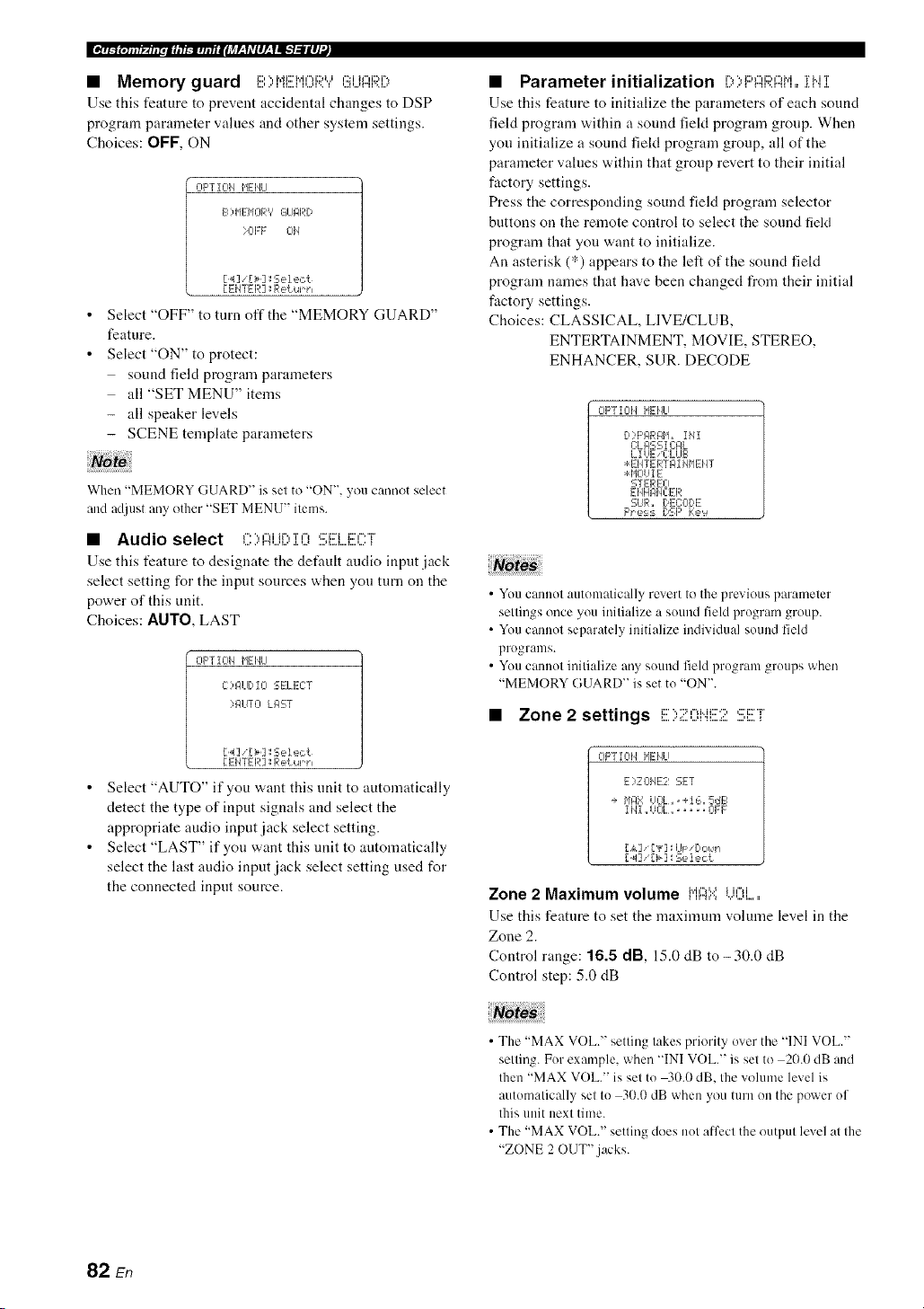
• Memory guard i:::,",,i.di:::'h.i¢"li::)tJ¢:::ih"d::M%
Use this feature to prevent accidental changes to DSP
program parameter values and other system settings.
Choices: OFF, ON
CIpTZCII_ HEIfiLI
F2) HEHORV GI_IIqRD
>0EF Cll/
[4]i[>]:Seiect
[EHTER ]:Return
Select "OFF" to turn off the "MEMORY GUARD"
feature.
Select "ON" to protect:
sound field program parameters
all "SET MENU" items
- all speaker levels
- SCENE template parameters
Wherl "MEMORY GUARD" is set to "ON", you cannot select
and adjust any other "SET MENU" items.
• Audio select ,".'.,,",J_r'.,'r,-,,:::J::r_c','-'r
Use this feature to designate the default andio input.jack
select setting for the input sources when you turn on the
power of this unit.
Choices: AIITO, LAST
CIF'T I CII_ HEIfiLI
C)121 [ I-- SELECT
>IqUTO LI:IST
[4] _[>]:Seiect
[ ENTER ]:Return
Select "AUTO" if you want this unit to automatically
detect the type of input signals and select the
appropriate audio input jack select setting.
Select "LAST" if you want this unit to automatically
select the last audio input jack select setting used for
the connected input source.
• Parameter initialization i)>I:::'i::IF;?J::?M=,iMi
Use this feature to initialize the parameters of each sound
feld program within a sound fiekt program group. When
you initialize a sound fiekt program group, all of the
parameter values within that group revert to their initial
factory settings.
Press the corresponding sound field program selector
buttons on the remote control to select the sound field
program that you want to initialize.
An asterisk (*) appears to the left of the sound field
program names that have been changed from their initial
factory settings.
Choices: CLASSICAL, LIVE/CLUB,
ENTERTAINMENT, MOVIE, STEREO,
ENHANCER, SUR. DECODE
CIF'TIC¢/ MEHLI
[,:'F'I_RI_H_ iMI
C:L#SS 1C:#L
LIUE _C:LLIB
:÷:EHTERTI_I MHEHT
:* HCIUI E
STEREO
EHHF41qC:ER
CUR. DEC:OI)E
F'_e:_:_DSF' Ke'_
• You cannot automatically revert to the previous parameter
settings once you initialize a sound field program group.
• You cannot separately initialize individual sound field
programs.
• You cannot initialize any sound feld program groups when
"MEMORY GUARD" is set to "ON".
• Zone 2 settings I;;;'",";:'I=,Mi;;;'';,(;;'i;;2"i"
OPTION HEHLI
E)ZOIqE2 SET
+ I'iFIX UOL,,+16,5dB
11'41,,UCIL,,, .... 01:F
L&] ['v] l:U_: [:',::,_.'l
[ _1] [>] : Se lect
Zone 2 Maximum volume l"il::iY,i...il:.'.',,i.....
Use this feature to set the nmximum volume level in the
Zone 2.
Control range: 16.5 dB, 15.0 dB to-30.0 dB
Control step: 5.0 dB
• The "MAX VOL." setting takes priority over the "INI VOL."
setting. For example, when "INI VOL." is set to 2(1.0dB and
then "MAX VOL." is set to 40.0 dB. the volume level is
automatically set to 30.0 dB when you turn on the power of
this unit next time.
• The "MAX VOL." setting does not alfcct the output level at the
"ZONE 2 OUT".jacks.
82 En

Zone 2 Initial volume iN]I UOi......
Use this feature to set the vohnne level of Zone 2 when the
power of this unit is turned on.
Choices: Off, -80.0 dB to +16.5 dB
Control step: 0.5 dB
• The "MAX VOL." setting takes priority over the "INI VOL."
setting.
• When you select "FRONT B', "PRNS" or "NONE" in
"EXTRA SP ASSIGN" (see page 72), "Zone 2 SP Not
Assigned" appears in the OSD and the "ZONE2 SET"
parameter is not available.
• The "INI VOL." setting does not affect the output level at the
"ZONE 2 OUT".jacks.
• XM Radio setting i::..,,...q.di:::,¢"H%'r,",c'i::'"F
OF'TIOH HEHU
F)',,q'l R61DiO SET
XH 61NTENNJq... 95'.
[ EHTER ] _Re{ur h
XM Radio antenna :::**i"il::i{".iFi!!!{".il".il::i
Use this feature to check the current reception level of the
XM Satellite Radio signals (see page 53). For the best
reception, orient the XM Mini-Tuner so that a value of
60% or more is displayed here.
Display status: NONE, 0 to 100%
_(qllf_.[ll[,li, mm,u#ilJ_r-_f,Vlll-_flg't:llll'._
• iPod universal dock setting ,:::,,rv,,'J..",:::'i::n
OPTIOH HENLI
6) bOC:K SET
STIqI'JDB'?C:HIqRGE_
IqUTO
[.4]/[> ] _Select.
[ ENTER ] : Return
Charge on standby C'"f',",Mr'.,i:::,i.J,'=q.J,",i:::,,':::i:::'
Use this feature to select whether this unit charges the
battery of the stationed iPod or not w,hen this unit is in the
standby mode (see page 58).
Choices: AUTO, OFF
• Select "AUTO" to charge the battery of the stationed
iPod when this unit is turned on and in the standby
mode.
• Select "OFF" to charge the battery of the stationed
iPod only when this unit is turned on.
"NONE" is displayed iflhe XM Mini-Tuner Dock is not
connecled to Ihis unil. In lhis case, check the anlenna connections
(see page 53).
I
83 En

In addition to controlling this unit, the remote control can also operate other audiovisual components made by Yamaha
and other manufacturers. To control your TV or other components, you must set up the appropriate remote control code
for each input source (see page 87).
• Controlling the input source
components in the SCENE mode
You can operate both this unit and the input source
component by using the remote control. You must set the
appropriate remote control code for each input source in
advance (see page 87).
1 Press the desired @SCENE button on the
remote control.
2 Press the desired buttons in the * area below
to control the input source component of the
selected SCENE template.
• Setting the input source of the
customized SCENE template on the
remote control
If you customize tile input source of the selected SCENE
template, you must set the input source of the SCENE
template on the remote control to operate the input source
component correctly.
1 Press the desired @SCENE button on the
remote control.
2 Press and hold the @SCENE button and the
desired input selector button (®).
Tile @TRANSMIT indicator flashes twice.
3 Keep holding down the buttons pressed in
step 2 until the @TRANSMIT indicator
flashes twice again.
SOURCE
If the setting of the input source is not successlul, the
@TRANSMIT indicator flashes repeatedly. In this case.
repeat the setup procedure.
SCENE
buttons
' These buttons control the input source componenl. See page 86
lk)r details ol Ihe funclion of each button.
84 En
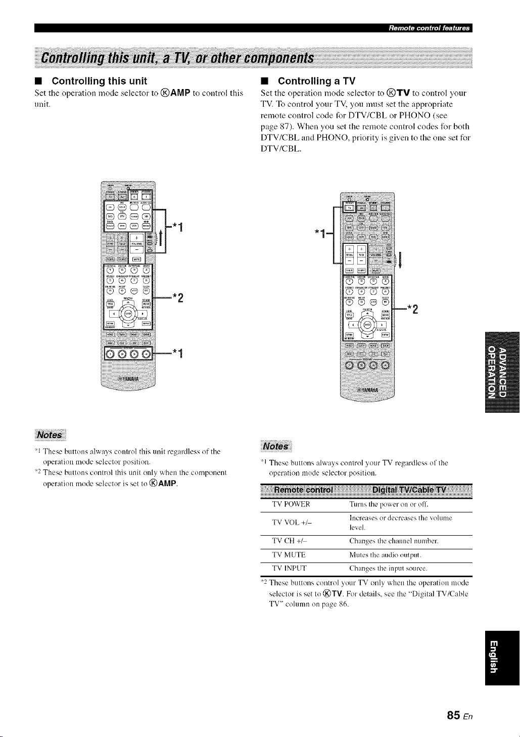
• Controlling this unit
Set the operation mode selector to @AMP to control this
unit.
• Controlling a TV
Set the operation mode selector to (_TV to control yonr
TV. To control your TV, you nmst set the appropriate
remote control code for DTV/CBL or PHONO (see
page 87). When you set the remote control codes for both
DTV/CBL and PHONO, priority is given to the one set for
DTV/CBL.
Q_QO
Q@O@
m. 2
m. 1
"1=
'1 These buttons always control this unit regaMless of the
operation mode selector position.
2 These buttons control this unit only when the component
operation mode selector is set to (_)AMP.
"1 These buttons always control your TV regardless of the
operation mode selector position.
TV POWER Turns the power on or off.
Increases or decreases tile volume
TV VOL +_
level.
TV CH +1 Changes the channel number.
TV MUTE Mutes the audio output.
TV INPUT Changes the input source.
"2 These buttons control your TV only when the operation mode
selector is set Io (_)TV. For details, see the "Digital TV/Cab]e
TV" column on page 86.
85 En

• Controlling other components
Set the operation mode selector to @SOURCE to control
other c()mponents selected with tile input selector button_
You must set the appropriate remote control code for each
input source in advance (see page 87). The following table
shows the function of each control button used to control
other components assigned to each input selector button.
Be advised that some buttons may not correctly operate
the selected component.
The remote control has 10 modes (input areas) to control
components so that the rmnote control can operate up to l0
di fli:rent components.
OOOO
©@@®
,_ AV POWER Power 1 Power _:1 Power *2 Power _ 1 Power * l Power _ l
'_ I-9,(1, +1(1 Numeric Numeric Numeric Numeric Numeric Numeric Preset slations
buoons buoons bum)ns butmns buttons buttons (1-8)
'_ TlTLE Title Band
'_ PRESET/CH Lip VCR channel Up Preset up (1-8) Lip
A up
PRESET/CH VCR channd Preset down
V Down down Down (1-8) Down
Preset down
A-E/CAT. <:] Le]l Lelt /A-E) Previous menu
A-E/CAT. C> Righl Righl Preset up Sub_quent
/A-E) menu
ENTER Enter Enter Sub_quent
lIl@l]ll
'_ RETURN Return Return
'@) REC Disc skip
(player) Rec Rec _'2 Disc skip Rec
Rec (recorder)
Play
Phty Phty Play 2 Play Play Play /Play/pause) 4
<3<1 Search Search Search Search Search Search Search
backward backward backward _2 backward backward backward backward 3
Search lk)rward Search lk_rward Searchlorward Search Iorward Search lorward Search lorward Searchlk)rward
2 '3
Patlse
Drl Pause Pause Pause '2 Pause Pause Pause
/Play/pause) 4
{<:]<l Skip backward Skip backward Skip backward Skip backward Skip backward Skip backward Skip backward
DE>[ Skip Iorward Skip Iorward Skip Iorward Skip Iorward Skip Ibrward Skip Ibrward Skip Ibrward
2
1-7 Stop Stop Stop *2 Slop Slop Stop Stop
'_ ENT Tille/lndex Enler Enler Chapter/Time hldex Index
'_ MENU Menu Menu Previous menu
'_ DISPLAY Display Display Display Display Display Display Disphty
'1 This button is operational only when the original remote control supplied with the component has a POWER button.
2 These buttons operate your VCR or DVD recorder only when you set the appropriate remote control code fl)r DVR (see page 87).
Press and hold to search backward or forward.
4 Simple remote mode (see page 58).
86 En
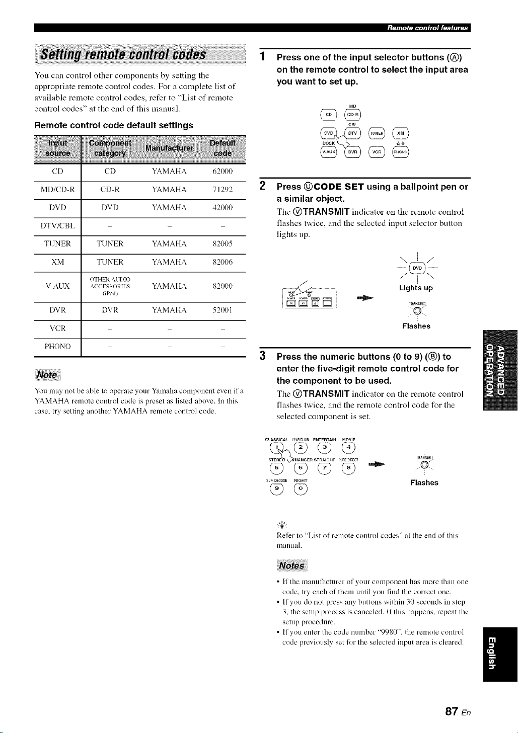
iPllil"l l_li_'ql I fi"t I[_'lfft|fi ,
You can control other components by setting the
appropriate remote control codes. For a complete list of
available remote control codes, refer to "List of remote
control codes" at the end of this manual.
Remote control code default settings
CD CD YAMAHA 621R)0
MD/CD-R CD-R YAMAHA 71292
DVD DVD YAMAHA 42(_I0
DTV/CBL
TUNER TUNER YAMAHA 82005
XM TUNER YAMAHA 82006
OTHER AUDIO
V-AUK AC'CI SSORII S YAMAHA 82(_)0
(iPod}
DVR DVR YAMAHA 521_11
VCR
PHONO
You may not be able to operate yOtll"Yamaha conlponenl even if a
YAMAHA remote control code is preset as listed above. In this
case. try selling another YAMAHA remote control code.
Press one of the input selector buttons (@)
on the remote control to select the input area
you want to set up.
CBL
(5 9@
Press @CODE SET using a ballpoint pen or
a similar object.
The @TRANSMIT indicator on the remote control
flashes twice, and the selected input selector button
lights up.
\E/
Lights up
TRA_SMI!
Flashes
Press the numeric buttons (0 to 9) ((_) to
enter the five-digit remote control code for
the component to be used.
The @TRANSMIT indicator on the remote control
flashes twice, and the remote control code for the
selected component is set.
CLASSICAL LE_OLIIB ENTI_RTAIN MOVIE
R S T PU_D_CT
q9 q9 q9
su_ oEe,0_ NIGHT
(9(9
TRagSMR
•"_ 50:1¸
Flashes
Refer to "List of remote control codes" al the end of this
manual.
• If the manufacturer of your componer/t has more thall one
code. try each of them until you find the correct one.
• If you do not press any buttons within 30 seconds in step
3. the setup process is canceled. If this happens, repeat the
setup procedure.
• If you enter the code number "9980". the remote control
code pmvkmsly set lor the selected input area is cleared.
87 En

Use this feature to clear all the remote control codes
previously set and reset all of them to the initial factory
settings.
Press @CODE SET using a ballpoint pen or
a similar object.
The @TRANSMIT indicator on the remote control
flashes twice.
TRA_rmIT
Flashes
Press the numeric buttons (®) to enter the
code number "9981".
The @TRANSMIT indicator on tire remote control
flashes twice, and all the remote control codes
previously set are cleared and reset to the initial
factory settings.
CLASSICAL LIV_CLUB ENTERTAIN MOVIE
SUR DEeX_DE NIGHT
TIIA,NSNI_
Flashes
If you do not press any buttons within 30 seconds after step
2. the clearing process is canceled. In this case. repeat the
clearing procedure.
88 En

This unit allows you to configure a multi-zone audio system. The Zone 2 feature allows you to set this unit to reproduce
separate input sources in the main zone and the second zone (Zone 2). You can control this unit from the second zone
using the supplied remote control.
Only analog signals are sent to the second zone. Any source you want to listen to in the second zone must he
connected to the analog AUDIO IN jacks of this unit.
You need the following additional equipment to use the nmlti-zone flmctions of this unit:
• An infrared signal receiver in the second zone.
• An infrared signal emitter in the main zone. This emitter transmits the infrared signals from the remote control via the
infrared signal receiver in the second zone to a CD player or a DVD player, etc. in the main zone.
• An amplifier and speakers in the second zone.
• Since there are many possible ways to commct and use this unit in a multi-zone configuration, we recommend that you consult with
your nearest authorized Yamaha dealer or service center about the Zone 2 connections that best meet your requirements.
• Some Yamaha models are able to connect directly to the REMOTE.jacks of this unit. If you own these products, you may not need to
use an infl'ared signal emitter. Up to 6 Yamaha components can be connected as shown below.
REMOTE REMOTE REMOTE REMOTE
,N,,. O0T'N"!__ __ OOT .....,,-
o I
Infrared signal This unit Yamaha Yamaha
receiver component component
• Using the external amplifier
Connect the amplifier/receiver in the second zone and other components to this unit as follows.
%
Main zone
I
DVD player This unit
/- Infrared signal cmillcr
(u
From the ZONE 2 OUT jacks
Amplifier
Second zone
(Zone 2)
From the REMOTE OUT jacks From the REMOTE IN jacks
To avoid mmxpecled noise. DO NOT USE the Zone 2 feature with CDs encoded in DTS.
.... Infrared signal receiver
89 En
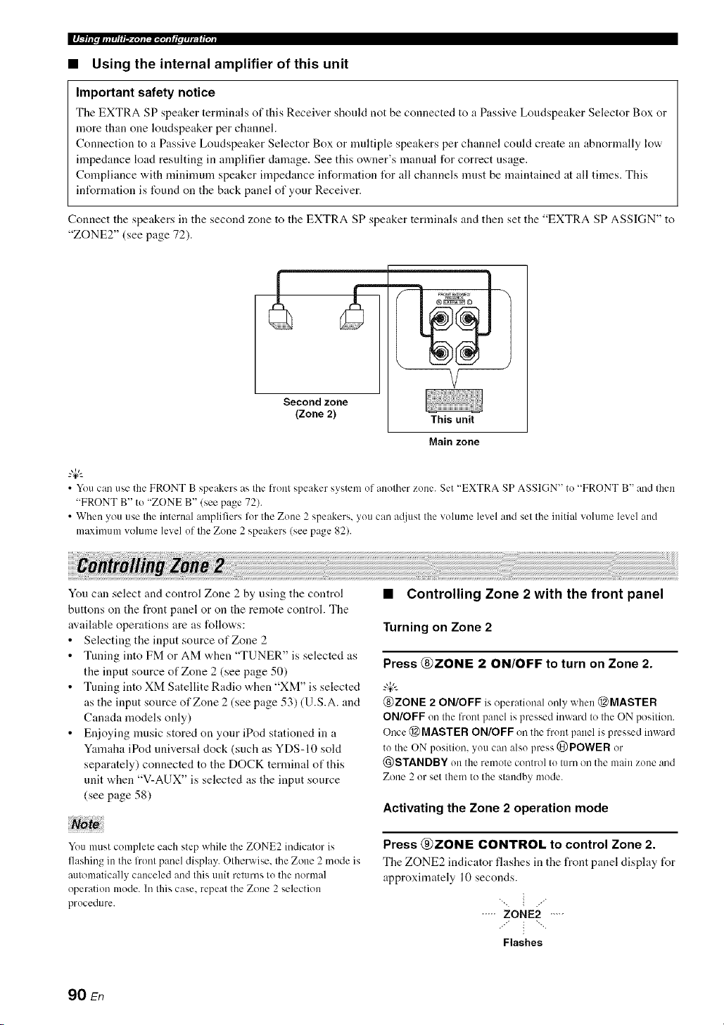
_ |.glIi II IIi i I #/I'1 _-_'llllalll'IIJi I III I #ltl I I llJl
• Using the internal amplifier of this unit
Important safety notice
The EXTRA SP speaker terminals of this Receiver should not he connected to a Passive Loudspeaker Selector Box or
more than one loudspeaker per channel.
Connection to a Passive Loudspeaker Selector Box or multiple speakers per channel could create an abnormally low
impedance load resulting in amplifier damage. See this owner's manual for correct usage.
Compliance with minimum speaker impedance information l\_r all channels must be maintained at all times. This
inff_rmation is found on the hack panel of your Receiver.
Connect the speakers in the second zone to the EXTRA SP speaker terminals and then set the "EXTRA SP ASSIGN" to
"ZONE2" (see page 72).
Second zone
(Zone 2)
This unit
Main zone
• You can use the FRONT B speakers as the front speaker system of another zone. Set "EXTRA SP ASSIGN" to "FRONT B" and then
"FRONT B" to "ZONE B" (see page 72).
• When you use the internal amplifiers lot the Zone 2 speakers, you can attiust the volume level and set the initial w)lume level and
maximum volume level of tile Zone 2 speakers (see page 82).
You can select and control Zone 2 by using the control
buttons on the front panel or on the remote control. The
available operations are as follows:
• Selecting the input source of Zone 2
• Tuning into FM or AM when "TUNER" is selected as
the input source of Zone 2 (see page 50)
• Tuning into XM Satellite Radio when "XM" is selected
as the input source of Zone 2 (see page 53) (U.S.A. and
Canada models only)
• Enjoying music stored on your iPod stationed in a
Yamaha iPod universal clock (such as YDS-10 sold
separately) connected to the DOCK terminal of this
unit when "V-AUX" is selected as the input source
(see page 58)
You must complete each step while the ZONE2 indicator is
flashing in the l?ont panel display. Otherwise, the Zone 2 mode is
automatically canceled and this unit returns to the normal
operation mode. In this case, repeat the Zone 2 selection
procedure.
• Controlling Zone 2 with the front panel
Turning on Zone 2
Press @ZONE 2 ON/OFF to turn on Zone 2.
@ZONE 2 ON/OFF is operational only when @MASTER
ON/OFF on the front panel is pressed inward to the ON position.
Once @ MASTER ON/OFF on the front panel is pressed inward
to the ON position, you carl also press @POWER or
@STANDBY on the remote control to turn on the main zone and
Zone 2 or set them to the standby mode.
Activating the Zone 2 operation mode
Press @ZONE CONTROL to control Zone 2.
Tile ZONE2 indicator flashes in the front panel display for
approximately 10 seconds.
"_ i ./
..... ZONE2 ....
:'" i "'"
Flashes
90 En

Operale the lollowing operalions after activating the Zone 2
operalion mode.
Operating Zone 2
Rotate the @INPUT selector to select the
desired input source while the ZONE2 indicator
is flashing in the front panel display.
• Select "TUNER" as the input source to use the TUNER
features in Zone 2. For details about the TUNER
operations, see "FM/AM tuning" on page 50.
• Select "XM" as the input source to use the XM
Satellite Radio features in Zone 2. For details about the
XM Satellite Radio operations, see "XM Satellite
Radio tuning" on page 53.
• Select "V-AUX" as the input source to use iPod
features in Zone 2. For details about the iPod
operations, see "Using iPod TM''on page 58.
Set Zone 2 to the standby mode
Press @ZONE 2 ON/OFF to set Zone 2 to the
standby mode.
• Setting the remote control to the Zone 2
mode
The remote control is originally set to the main mode to
control the main zone. To control Zone 2 with the remote
control, you must first set the remote control to the Zone 2
mode.
Press @CODE SET using a ballpoint pen or
a similar object.
The @TRANSMIT indicator on the remote control
flashes twice.
TRAQ_MIT
Flashes
2 Press the numeric buttons (®) to enter the
code number "9992".
CLASSICAL LiVFJCLVB ENTERTAIN MOVIE
STEREO E T PURE_¢I TRA_SMI1
SURDECODE NIGHT
F,ashes
Wl.._llafm|lHIl_"Xelal:.iDqolallfmlIIt;tt[oll
• Controlling Zone 2 with the remote
control
Turning on Zone 2
Press and hold @POWER or @STANDBY and
then press @,;,_,:_to set the remote control to the
Zone 2 mode.
• Press @POWER when the main zone is turned on.
• Press @STANDBY when the main zone is turned ofl.
The @TRANSMIT indicator on the remote control lights
up while the remote control is set to the Zone 2 mode.
While holding
> down
or
%-
Lights up
• When the rmnote control is set to the Zone 2 mode.
@POWER, @STANDBY, @VOLUME */-, C)MUTE, :rod
the input selector buttons are set to control Zone 2. However.
the rest of the remote control buttons remain in the main mode.
• The remote control automatically exits from the Zone 2 mode in
the lollowing cases:
when you do not make any operations within 10 seconds after
the remote control is set to the Zone 2 mode.
when you press a remote control button other than
@POWER, @STANDBY, @VOLUME */-, (_)MUTE,
and the input selector buttons.
Activating the Zone 2 operation mode
Press @POWER to turn on Zone 2.
Operating Zone 2
Press one of the input selector buttons (@) to
select the desired input source of Zone 2.
Setting Zone 2 to the standby mode
Press @STANDBY to set Zone 2 to the standby
mode.
91 En
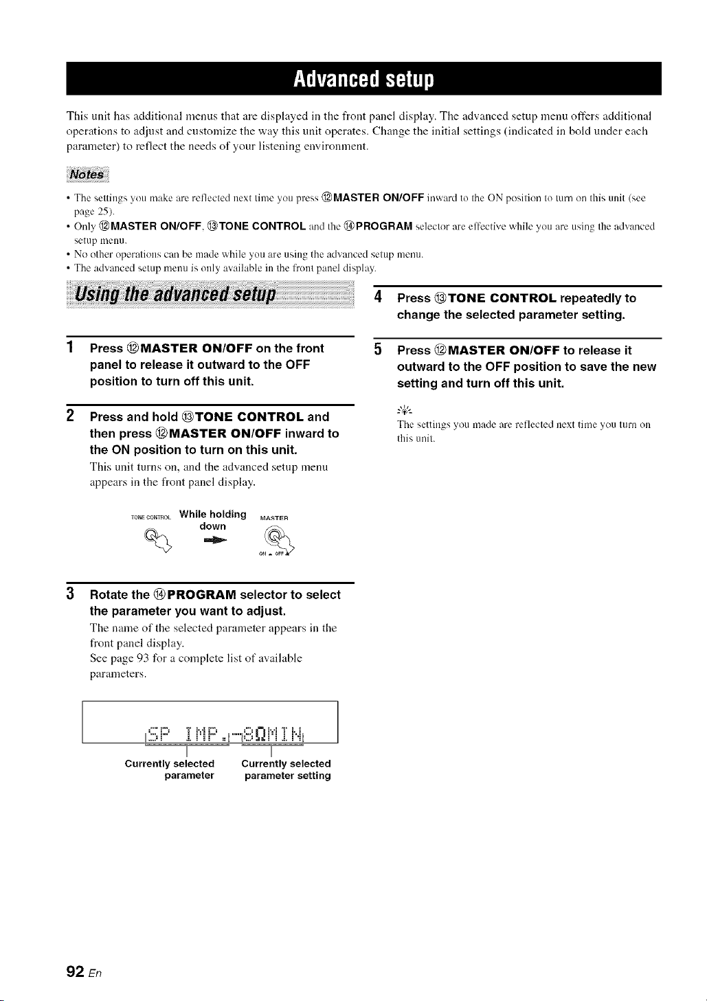
This unit has additional menus that are displayed in the front panel display. The advanced setup menu offers additional
operations to adjust and customize the way this unit operates. Change the initial settings (indicated in bold under each
parameter) to reflect the needs of your listening environment.
• The settings you make are reflected next time you press @MASTER ON/OFF inward to the ON position to turn on this unit (see
page 25).
• Only @MASTER ON/OFF, @TONE CONTROL and the @PROGRAM selector are effective while you are using the advanced
setup nmnn.
• No other operations can be made while you are using the advanced setup menu.
• The advanced setup menu is only available in the front panel display.
_ th_ __ 4 Press(_)TONE CONTROL repeatedlyto
change the selected parameter setting.
Press (_MASTER ON/OFF on the front
panel to release it outward to the OFF
position to turn off this unit.
Press and hold _)TONE CONTROL and
then press (_MASTER ON/OFF inward to
the ON position to turn on this unit.
This unit turns on, andthe advanced setup menu
appears in the front panel display.
Press (_MASTER ON/OFF to release it
outward to the OFF position to save the new
setting and turn off this unit.
-&
The settings you made are reflected next timeyou turn on
this tmil.
Rotate the (_ PROGRAM selector to select
the parameter you want to adjust.
The name of the selected parameter appears in the
front panel display.
See page 93 for a complete list of available
parameters.
.,,,. =,% ,:, =..: =,%
Currently selected Currently selected
parameter parameter setting
92 En

(, • 9_
See pa_.e . h)r the operalicm of the advanced setup.
• Speaker impedance ................
*...i..., i r,'ll..,
....,_ a.l II •
Use this feature to set the speaker impedance of this unit
so that it matches that of your speakers.
Choices: 8_Q MIN 6_Q MIN
• Select "8f2 MIN" to set the speaker impedance to 8 f2
• Select "6f2 MIN" to set the speaker impedance to 6 L)
8__)MIN
6_ MIN
Front
If you use one set (A or B),
the impedance of each
speaker must be 8 t) or
higher.
If you use two sets (A and
B), the impedance of each
speaker must be 16 t) or
higher."
Center
The impedance of each
Surround speaker must be 8 _ or
higher.
Surround back
Front
If you use one set (A or B),
the impedance of each
speaker must be 4 t) or
higher.
If you use two sets (A and
B), the impedance of each
speaker must be 8 t) or
higher.
Center
The impedance of each
Surround speaker must be 6 _ or
higher.
Surround back
• Remote control AMP ID i:;?.EMI;'TEl:ir"il:::'
Use this feature to set the AMP ID of this unit t_r remote
control recognition. This feature is useful when you
operate this unit and the other Yamaha receivers/
amplifiers in the same room separately.
Choices: ID1, ID2
• Select "lDl" when the remote control AMP ID code is
set to "00001 ".
• Select "lD2" when the remote control AMP ID code is
set to "00002".
Setting remote control AMP ID codes
You need to set the remote control AMP ID code for the
remote control.
Press @CODE SET using a ballpoint pen or
a similar object.
The @TRANSMIT indicator on the remote control
flashes twice.
mA_SMIT
Flashes
Press the numeric buttons (®) to enter the
code number "00001" or "00002".
The @TRANSMIT indicator on the remote control
flashes twice, and the AMP ID code is changed.
CLASSICAL LIV_CLUB ENTERTAIN MOVIE
STEREO E T TRA_SMI_
$U_,DE_0DE
Flashes
'_ The Canada model canm)t use two separate speaker systems
(A and B) simullaneously when "SP IMP." is set to "8f2MIN".
• User presets i::)i:::,c',i::'i::_'Ti r,,L,,,,,,q,,,, i
Use this feature to reset all the parameters of this unit to
the initial factor), settings (see page 103).
Choices: CANCEL, RESET
• Select "CANCEL" not to reset any parameters of this
unit.
• Select "RESET" to reset the parameters of this unit.
Noia :
• This setting completely resets all the parameters of this unit
including the "SET MENU" parameters.
• The initial lhctory settings are activated next time you turn on
this unit.
00001 To operate this unil using IDI
(inilial setting) the defauh code. /inilial setting)
00002 To operate this unil using ID2
an a]lernalive code.
_1 The rmnole conlrol setting
2 The selting of this trail
93 En

1
See pa_.e . for [he operation of the advanced setup.
• Remote control TUNER ID F;;:i!!:MOTi!!!:iq...ii..i
Use this feature to set the TUNER ID of this unit for
remote control recognition.
Choices: ID1, ID2
• Select "IDI" when the remote control TUNER ID code
is set to "82005".
• Select "ID2" when the remote control TUNER ID code
is set to "81949".
Setting remote control TUNER ID codes
You need to set the remote control TUNER ID library
code for the remote control.
Press @TUNER to select "TUNER" as the
input source.
%
Press @CODE SET using a ballpoint pen or
a similar object.
The @TRANSMIT indicator on the remote control
flashes twice.
TRA_SNI_
Flashes
Press the numeric buttons (®) to enter the
code number "82005" or "81949".
The @TRANSMIT indicator on the remote control
flashes twice, and the TUNER ID code is changed.
CLASSICAL LEad/CLUB ENTERTAIN MOVIE
STER _',_, '_N HA N C ER STRAIGHT PU_ D_x '], _ TRA_SNI!
SU_[ECOE_ NIGHT "_,j]," :
@ Flashes
• Remote control XM ID REi407E :@i
(U.S.A. and Canada models only)
Use this feature to set the XM ]D of this unit for remote
control recognition.
Choices: ID], ID2
• Select "IDI" when the remote control XM ID code is
set to "82006".
• Select "ID2" when the remote control XM ID code is
set to "82007".
Setting remote control XM ID codes
You need to set the remote control XM ID code for the
remote control.
1 Press @XM to select "XM" as the input
source.
%
Press @CODE SET using a ballpoint pen or
a similar object.
The @TRANSMIT indicator on the remote control
flashes twice.
TRANSMIT
1
Flashes
Press the numeric buttons (®) to enter the
code number "82006" or "82007".
The @TRANSMIT indicator on the remote control
flashes twice, and the XM ID code is changed.
CLASSICAL UV_OLUB ENTERTAIN MOVIE
STEREO ENHAi_t_'],STRAIGHT pU_ENREC'_ TRA_iSNI_
$UR DE¢09E NIGHT
@ @. F,ashes
82005 To operale this unil using [DI
(initial selting) Ihe defaull code. (initial selting)
81949 To operale this unil using ID2
an allernalive code.
'1 The remote control selling
'2 The setting of this unit
82006 To operate this unit using IDI
(initial setting) the default code. (initial setting)
.................................................................................................
82(t(}7 To operate Ihis unit using ID2
an alternative code.
'1 The remote control setting
'2 The setting of this trait
94 En

(, • 9_
See pa_.e , lot the operalion of the advanced setup.
• SCENE IR code setting :!!!;_2i!!!l..ii!!:]:R
Use this feature to output the remote control signals at the
REMOTE OUT jack automatically when this unit is in the
SCENE mode.
Choices: ON, OFF
• Select "ON" when the component connected to the
REMOTE OUT jack is the Yamaha component and has
the capability of the SCENE control signals. This unit
automatically sends the remote control signals to the
component.
• Select "OFF" when the component connected to the
REMOTE OUT jack is not the Yamaha component and
does not have the capability of the SCENE control
signals.
=T;i'tqli'i'fiplC_|q,
11noises are output when you operate the SCENE function, set
"SCENE IR" to "OFF".
• Bi-amplifier setting ,...,_:::'.,.'r""i"D,...,,,,
Use this feature to activate or deactivate the bi-amplifier
function (see page 14).
Choices: ON. OFF
• Select "ON" if you want to activate the bi-amplifier
flmction. "SUR. B L/R SP" is set to NONE"
automatically, and this unit outputs the front channel
audio signals at the SURROUND BACK speaker
terminals.
• Select "OFF" if you want to deactivate the bi-amplifier
/unction.
When "BI-AMP" is sel Io "ON", you can only selecl "FRONT B"
or "NONE" in "EXTRA SP ASSIGN" (see page 72).
• Tuner frequency step '{i..j
(Asia and General models only)
Use this feature to set the tuner frequency step according
to the t_equency spacing in your area.
Choices: AM10/FM100, AM9/FM50
• Select "AMI0/FMI00" for North, Central and South
America.
• Select "AM9/FM50" for all other areas.
95 En
Refer to the table below when this unit does not function properly. If the problem you are experiencing is not listed below
or if the instruction below does not help, turn off this unit, disconnect the power cable, and contact the nearest authorized
Yamaha dealer or service center.
• General
This unit fails to turn Tile power cable is not connected or the Connect the power c_d_le firmly.
on or enters the plug is not completely inserted.
standby mode soon
alter the power is The spealkcr impedance scqting is Set Ihc speaker impedance to malch 5r_ll" speakers. 25
turned on. incorrect.
The protection circuitry has been Make sure that all speaker wire connections on this 13
activated, unit and on all speakers are secure and that the wires
for each connection do not touch anything other than
their respective connections.
This unit has been exposed to a strong Set this unit to the standby mode, disconnect the
external electric shock (such as lightning power c_d_le, plug it back in afler 3(1 seconds and dlen
or strong static electricity), use this unit normally.
No sound. Incorrect input or output cable Connect the c_d_les properly. If the problem persists, 18-23
connections, the cables may be defective.
The optimizer microphone is connected. Disconnect the optimizer microphone. 3 I
Audio input jack select is set to "HDMI', Set Audio input jack select to "AUTO". 39
"COAX/OPT" or "ANALOG".
Audio input jack select is set to Set Audio input jack select to "AUTO" or 39
"ANALOG" while playing a source "COAX/OPT'.
encoded in Dolby Digital or DTS.
No appropriate input source has been Select an appropriate input source with the INPUT 37.38
selected, selector on the front panel/or the input selector
buttons on the remote control).
Speaker connections are not secure. Secure the connections. 13
The front speakers to be used have not Select the front speakers by pressing @SPEAKERS 38
been selected properly, on the front panel repeatedly.
The volume is turned down. Turn up the vohlme.
The sound is muted. Press @MUTE or @VOLUME +/- on the remote 40
control to resume audio output and then a(!iust the
volume.
Signals Ihis unit cannot reproduce arc. Play a source whose signals can be reproduced by this
being input from a source component, unit.
such as a CD-ROM
The HDMI components connected to this Connect HDMI components that support the HDCP 16
unit do not support the HDCP copy copy protection standards.
protection standards.
"SUPPORT AUDIO" is set to "OTHER" Set "SUPPORT AUDIO" to "RX-V661" in 77
and "HDMI" audio signals are not being "MANUAL SETUP".
played back on this unit.
No picture. The output and input l_r the picture are Set "V CON',/." to "ON" or connect your source 8 I
connected to difli_.rent types of video components in the same way as you connect your
jacks, video monitor to this unit.
Non-standard video signals are input.
96 En
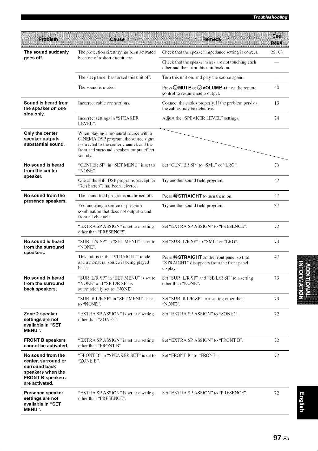
The sound suddenly
goes off.
The protection circuitry has been activated
because of a short circuit, etc.
Check that the speaker impedance setting is correct. 25.93
Check that the speaker wires are not touching each
other and then turn this unit back on.
The sleep timer has turned this unit off. Turn this unit on, and play the source again.
The sound is muted. Press (DMUTE or @VOLUME +/- on the remote 40
control to resume audio output.
Sound is heard from Incorrect cable comlections. Connect the cables properly. If the problem persists, 13
the speaker on one the cables may be deli:ctive.
side only.
Incorrect settings in "SPEAKER A([just the "SPEAKER LEVEL" settings. 74
LEVEL".
Only the center When playing a monaural source with a
speaker outputs CINEMA DSP program, Ihe source signal
substantial sound, is directed Io Ihe center channel, and Ihe
fronl and surround speakers outpul effect
sounds.
No sound is heard "CENTER SP" in "SET MENU" is set to Set "CENTER SP'' to "SML" or "LRG'L 73
from the center "NONE".
speaker.
One of the HiFi DSP programs (except for Try another sound field program. 42
"7ch Stereo") has been selected.
No sound from the The sound field programs are turned oil'. Press @STRAIGHT to turn them on. 47
presence speakers.
You arc using a source or program Try another sound field program. 37
combination that does not output sound
liom all channels.
"EXTRA SP ASSIGN" is set to a setting Set "EXTRA SP ASSIGN" to "PRESENCE". 72
other than "PRESENCE".
No sound is heard "SUR. L/R SP" in "SET MENU" is set to Set "SUR. L/R SP" to "SML" or "LRG'. 73
from the surround "NONE".
speakers.
This unit is in the "STRAIGHT '' mode Press @STRAIGHT on the liont panel so that 47
and a monaural source is being played "STRAIGHT" disappears from the front panel
back. display.
No sound is heard "SUR. L/R SP" in "SET MENU" is set to Set "SUR. L/R SP" and "SB L/R SP" to a setting 73
from the surround "NONE" and "SB L/R SP" is other than "NONE".
back speakers, automatically set to "NONE".
"SUR. B [JR SP" in "SET MENU" is set Set "SUR. B L/R SP" to a setting other than 73
to "NONE". "NONE".
Zone 2 speaker "EXTRA SP ASSIGN" is set to a setting Set "EXTRA SP ASSIGN" to "ZONE2". 72
settings are not other than "ZONE2".
available in "SET
MENU".
FRONT B speakers "EXTRA SP ASSIGN" is set to a setting Set "EXTRA SP ASSIGN" to "FRONT B'. 72
cannot be activated, other than "FRONT B'.
No sound from the "FRONT B" in "SPEAKER SET_' is set to Set "FRONT B" to "FRONT". 72
center, surround or "ZONE B'.
surround back
speakers when the
FRONT B speakers
are activated.
Presence speaker "EXTRA SP ASSIGN" is set to a setting Set "EXTRA SP ASSIGN" to "PRESENCE". 72
settings are not other Ihan "PRESENCE".
available in "SET
MENU".
97 En

IIT;Tfi,3F_b'7;T_hl r
No sound is heard "LFE/BASS OUT" in "SET MENU" is Set "LFE/BASS OUT" to "SWFR" or "BOTH". 72
from the subwoofer, set to "FRONT" when a Dolby Digital or
DTS signal is being phlyed.
"LFE/BASS OUT" in "SET MEN U" is Set "LFE/BASS OUT" to "BOTH". 72
set to "SWFR" or "FRONT" when a 2-
channel source is being played.
Tile source does not contain low-
fiequency signals.
Dolby Digital or DTS Tile connected component is not set to Make an appropriate setting 12)llowing the operating
sources cannot be output Dolby Digital or DTS digital instructions for your component.
played. (Dolby Digital signals.
or DTS indicator in
the front panel Audio input jack select is set Io Set Audio inpul jack select to "AUTO". 39
display does not light "ANALOG".
up.)
A humming sound is Incorrect cable connections. Connect the :radio cables firmly. If the problem
heard, persists, the cables may be defective.
No connection from Ihe turntable to Ihe Connect the grounding cable of your turntable to the 2 I
GND terminal. GND temdnal of this unit.
The volume level is The record is being played on a turntable Connect your turntable to tiffs unit tlmmgh an MC- 2 I
low while a record is with an MC cartridge, head amplifier.
being played.
The volume level The component connected to the AUDIO Turn on tile power of the component.
cannot be increased, OUT (REC) jacks of this unit is turned
or the sound is off.
distorted.
The sound effects It is not possible to record the sound
cannot be recorded, effects with a recording component.
A source cannot be The source component is not connected to Connect the source component to tile DIGITAL 19, 21
recorded by a digital the DIGITAL INPUT jacks of tiffs unit. INPUT jacks.
recording component
connected to the Some components cannot record Dolby
DIGITAL OUTPUT Digital or DTS sources.
jack.
A source cannot be The source comlxmcnt is not connected to Connect the source component to the analog AUDIO 2 I
recorded by an the analog AUDIO IN .jacks of tiffs unit. IN jacks.
analog component
connected to the
AUDIO OUT (REC)
jacks.
The sound field "MEMORY GUARD" in "SET MENU _ Set "MEMORY GUARD" to "OFFL 82
parameters and some is set to "ON".
other settings of this
unit cannot be
changed.
This unit does not The internal microcomputer has been Disconnect the power cable from the AC wall outlet
operate properly, fiozen by an external electric shock (such and then plug it in again after about 30 seconds.
as lightning or excessive static electricity)
or by a power supply with low voltage.
No sound is heard The HDMI component does not accept Ihe Convert the multi_channel audio signals to the 2-
from the connected multi-channel audio signals, channel audio signals at tile source component such
HDMI component, as a DVD player.
98 En
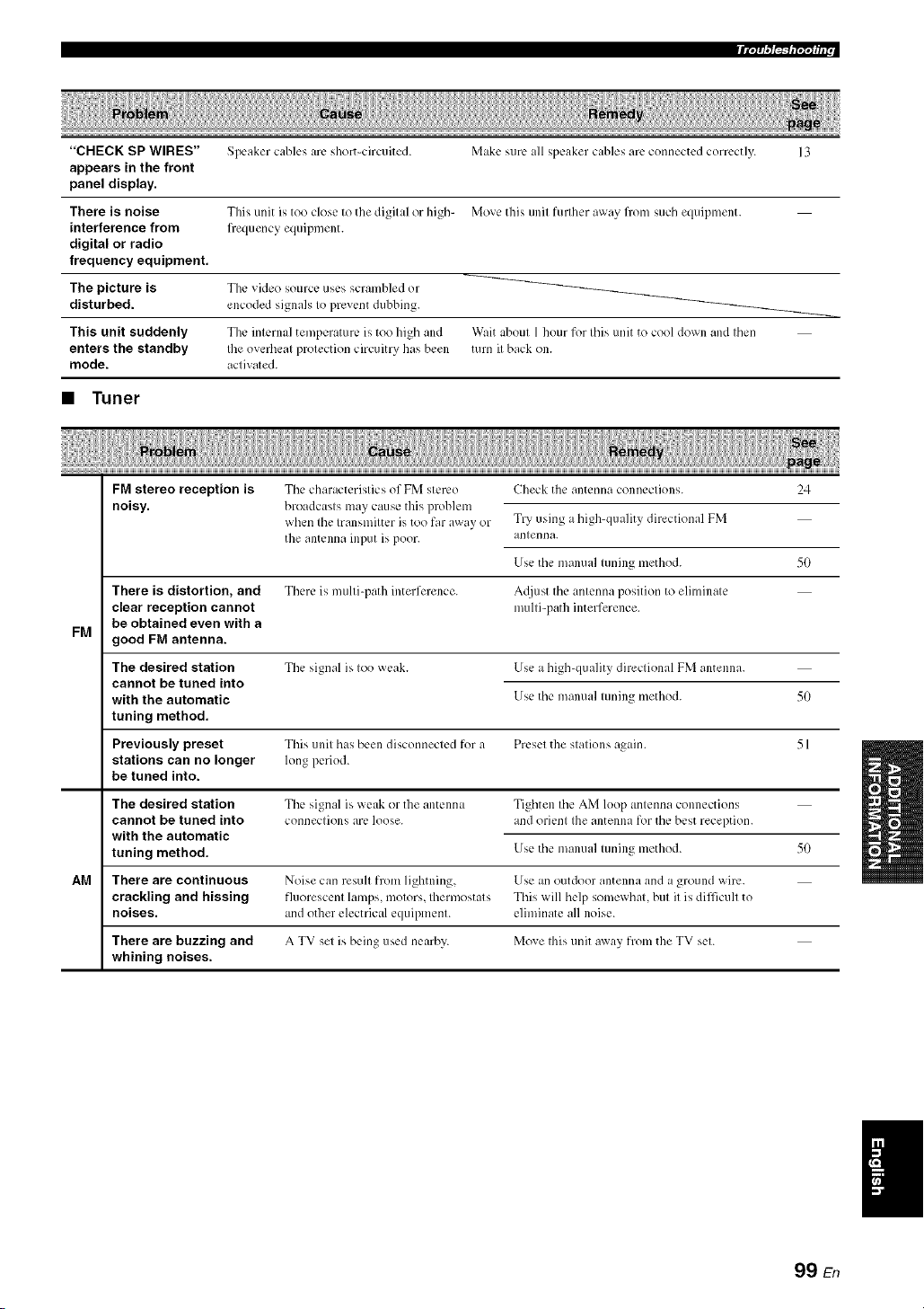
"CHECK SP WIRES"
appears in the front
panel display.
There is noise
interference from
digital or radio
frequency equipment.
The picture is
disturbed.
This unit suddenly
enters the standby
mode.
Speaker cables arc short-circuited.
This unit is too close to the digital or high-
frequency equipment.
The video source uses scrambled or
encoded signals to prevent dubbing.
The internal temperature is too high and
Ibe overheat protection circuitry has been
activated.
Make sure all speaker cables arc connected correctly.
Move this unit furlher away flom such equipment.
Wait about 1 hour for this unit to cool down and then
turn it back on.
• Tuner
FM
AM
FM stereo reception is
noisy.
There is distortion, and
clear reception cannot
be obtained even with a
good FM antenna.
The desired station
cannot be tuned into
with the automatic
tuning method.
Previously preset
stations can no longer
be tuned into.
The characteristics of FM stereo
broadcasts may cause this problem
when the transmitter is too far away or
the antenna input is poor.
There is multi-path interference.
The signal is too weak.
Check the antenna connections. 24
Try using ahigh-quality directional FM
antenna.
Use the manual tuning method. 50
A_[just the antenna position to eliminate
multi-path interference.
Use a high-quality directional FM antenna.
Use the manual tuning method. 50
The desired station
cannot be tuned into
with the automatic
tuning method.
This unit has been disconnected for a Preset the stations again. 51
long period.
The signal is weak or the antenna Tighten the AM loop antenna connections
connections arc, loose, and orient the antenna lk_rthe best reception.
Use the manual tuning method. 50
There are continuous Noise can result from lightning, Use an outdoor antenna and a ground wire.
crackling and hissing fluorescent lamps, motors, thermostats This will help somewhat, but it is difficult to
noises, and other electrical equipment, eliminate all noise.
There are buzzing and A TV set is being used nearby. Move this unit away from the TV set.
whining noises.
99 En

m Ir'/;_ ,"/i_'ql"l';l_ i i r
• XM Satellite Radio
If an operation takes longer than usual or an error occurs, one of tile following messages may appear in tile front panel
display. In this case, read the cause and follow the corresponding remedies.
,-q...ii:::'t-q...',"lHTC'i..ii..il", The XM Mini-Tuner and XM Dock f/re Check XM Mini-Tuner and XM Dock connections 53
,...i H.. ,....i '.. r".q "., i L.. i ".q ".q'l
nol connecled to Ihe XM .iack of Ihis unil and orienl for the best reception level.
or do not work properly.
,...+_iii:::,i",,"+"i"_....r...,i .i.i"v..aTi..h':.': The XM user encryption code is being Wait unti] the encryplion code ix tlpdaled.
updated.
lit"+1"1_*...t....+t::r.I.T*...HC:i"i¢"+i".q".q.... The sivnal is too weak. Adjust the orientation of the XM Mini-Tuner for the 53
besl reception level.
1....0{:::11_)]i 1'..11!_ Ittakes longer Ihan four seconds lk)raudio Wait until Ihe decoding process has finished.
or lext data Io be decoded.
,-_::'i:::'_","ri:::, The xm Sate]lile Radio channel vou Check tile channel number a_ain or select another
,...q i m a. v. ....
selected is nol currenlly broadcasting any XM Salellite Radio channel.
signals.
"'...r.,__...,i.,.i_...'................. The Channel Stalion ID (SID) is no longer
available.
............... .." -.............. No artisl name or song litle ix available.
':;iC:{:::ITi::................ No channels are available for Ihe selected Selecl anolher channel category by, pressing 55
calegory. @CATEGORY on the fronl panel (or @A-E/CAT.
<:3/[::>on Iheremole control) repeatedly.
• Remote control
The remote control Wrong dislance or angle. The remole conlro] will functk)n wilhin a maximum
does not work or range of 6 m (20 fl) and no more Ihan 30 degrees off- 27
function properly, axis flom Ihe fro]it panel.
Direct sunlighl or lighting (l¥om an Reposition this unit.
ire'crier lype of fluorescent lamp, elc.) is
slriking the remote connol sensor of this
unil.
The baneries are weak. Replace all balleries.
The operation mode seleclor ix sel
incorrectly.
Set the operation mode selector correctly.
When operating this unit, set it to the @AMP
positkm.
Whenoperatingthe component selectedby the input
selectorbutton, setit to II_e_)SOURCE position.
When operating the TV set in the DTV or PHONO
area, set it to the (_)TV position.
The remote control code was not correctly Set the remote control code correctly using "List of
87
set. remote control codes" at the end of this manual.
Try setting another code of the same manufacturer
using "List of remote control codes" at the end of this 87
ii/antla].
The ID code of Ihe remote conlro] and Ihe Match the remole conlrol ID of Ihis unil wilh the
remote control ID of dais unil do not corresponding remote conlrol ID code. 93
l_lalcll.
100 En
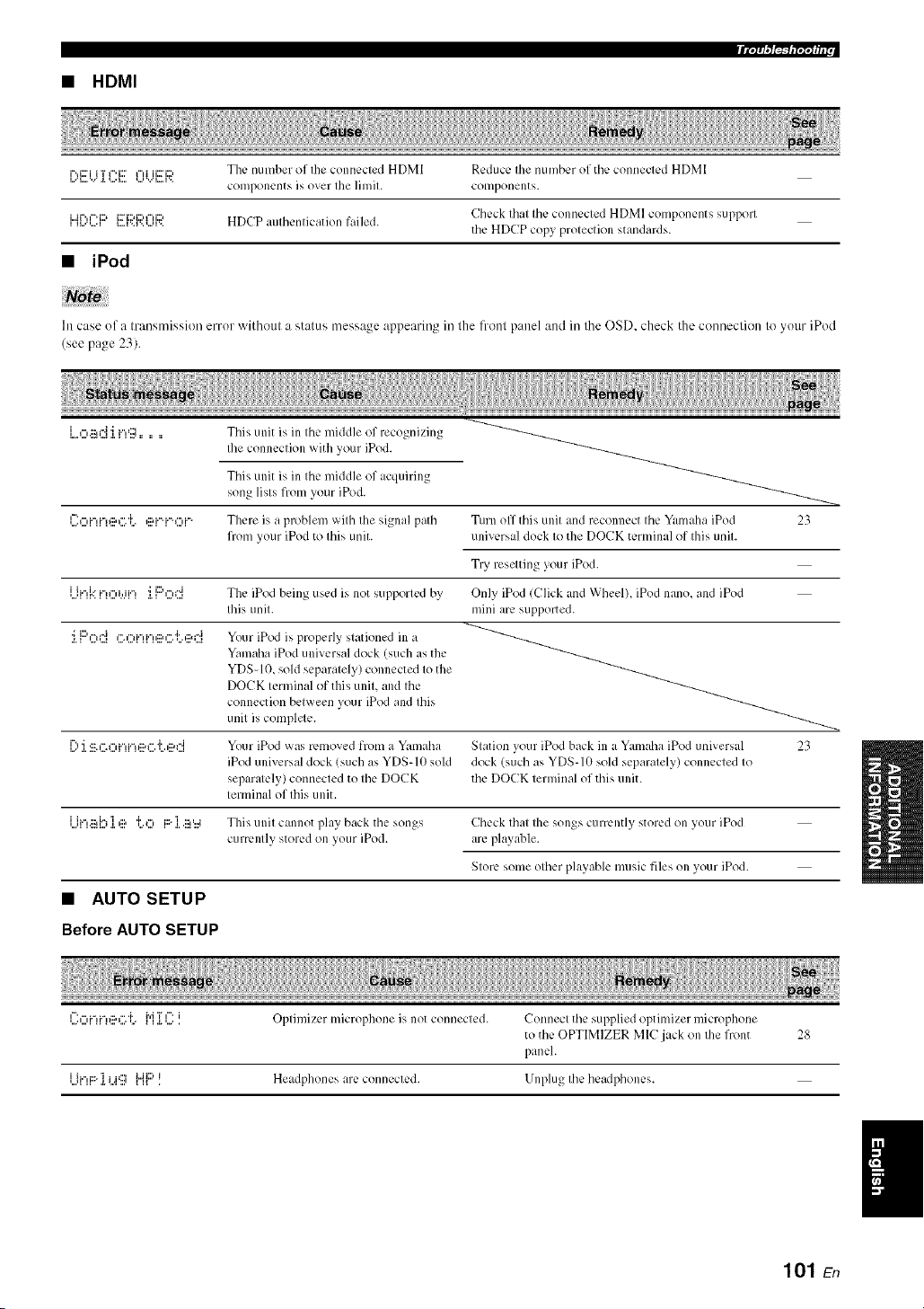
• HDMI
i%i='i i T I"'i=' I"d ii:_iD ThL, number of [lie connL, L-led HDM[ RL'dLIcL' [lle [ILII]]bL'r of [ILL' conneclL, d HD]_I
components i'; over Ihe ]imil. componems.
i.jr..,¢-q::> i:::_i::M:::u...d:::, Cll¢ck Illal I11¢ conn¢cled HDMI COlilpon_:nts SUll)porl
i ,...',....i i....v,v..,...,v, HDCP aulbcnlication failed.
the HDCP copy proleclion standards.
• iPod
In case of a transmission error without a status message appearing in lhe lronl panel and in lhe OSD. check the conneclion to your iPod
(see pa,*e _3)
Tiffs unit is in the middle of recognizing
Ihe connection with your iPod.
Tiffs unit is in the middle of acquiring
song lists from your iPod.
l::o[.-H.-!@G 'i.. @[.-q.-.O[.-, There is a problem with the signal path Turn off this unit and reconnect the Yal_mhaiPod 23
from your iPod to this unit. universal dock to the DOCK terminal of this unit.
Try reselting your iPod.
Ui",kn,:::,_.,.in:i.F'od The iPod being used is not supporled by' Only' iPod (Click and Wheel), iPod nano, aM iPod
Ibis unil. mini are supported.
J.1:::'0(7{,".,"ii.",F,,::a,".'l'.,::ar4Your iPod is properly slationed ill a
Yamaha iPod universal dock (such asthe
YDS-10, sold separalely) connected Io the
DOCK lerminal of tiffs unil, and Ihe
connection belween your iPod and Ibis
unil is complele.
[) 'i ':::.,"=_",F',i"n::a_".']'.,::M"[ Your iPod was removed from a Yan]aha Slation your iPod back ill a Yamalla iPod universal 23
iPod universal dock (such as YDS-lit sokl (lock (such as YDS-lit sold separalelv connected Io
separalely) connecled to Ibe DOCK the DOCK lernfinal of this unit.
lerminal of lifts unit.
Ili.",.:::d.'lI_:::,"I'._",J:::.I .:::_,..4 Tiffs unil canllot play back the songs Check Ibal Ihe songs currently stored on your iPod
currenlly stored on your iPod. are playable.
SIore some olber playable music files on your iPod.
• AUTO SETUP
Before AUTO SETUP
l":_"d"d"lg:,_".'L {"[]i I:::.i Oplimizer microphone is not connecled. Connecl the supplied optimizer microphone
to the OPTIMIZER MIC jack on Ihe front 28
panel.
]...............iF'H:::"'[ i .iC:] _i_kiD.{ Headphones are connecled. Unplug Ibe headphones.
101 En
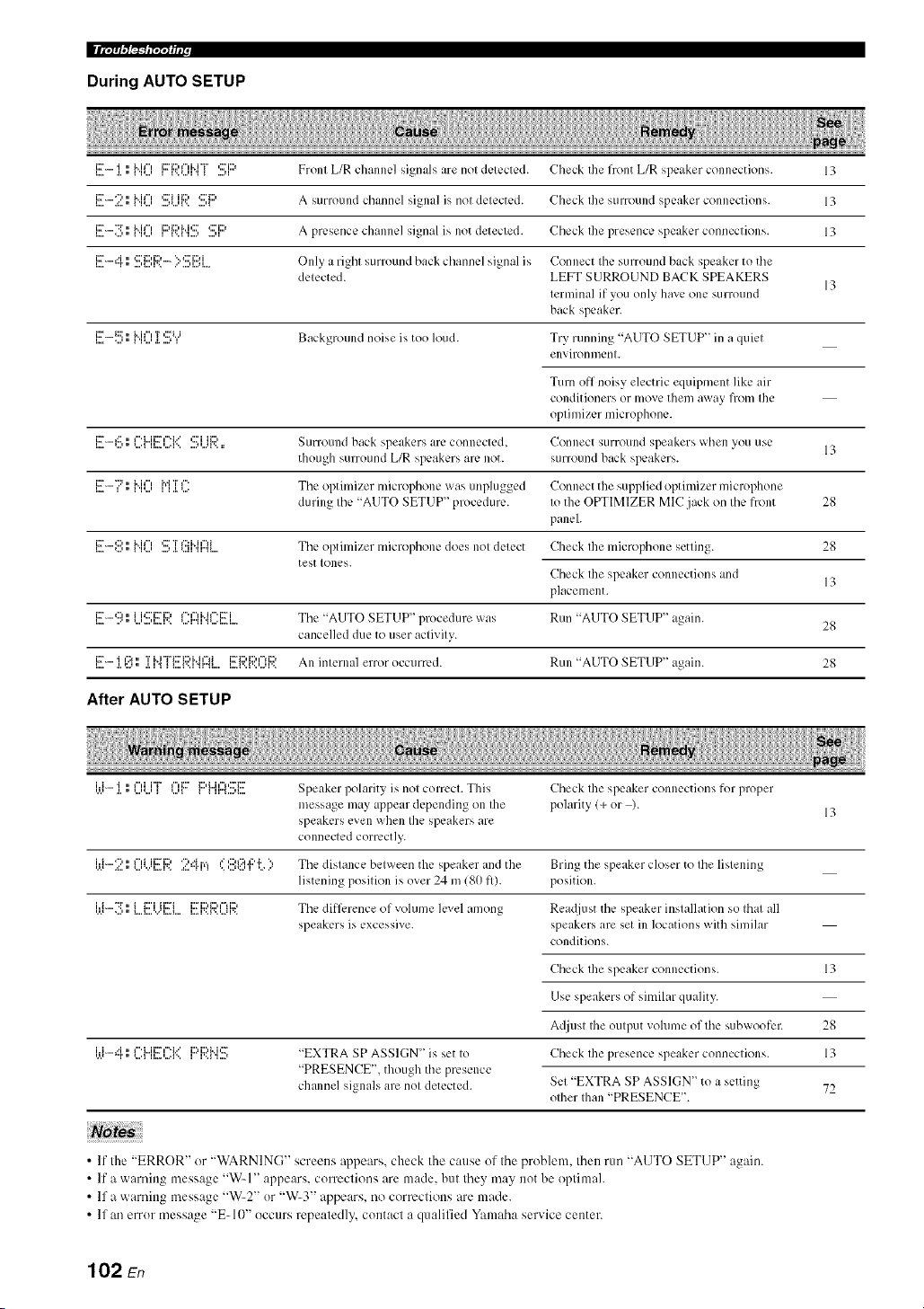
II i'/;'/'t/,"/_'2_I"/';Y_ i i r
During AUTO SETUP
l....i::_".... .l.'i,,"I 'l_...'i.. i i"i li::_'ii::'I"ii"i"i"l'..'...'l_ _ ....q'::'i::) Front L/R chtlnllL'] signals< ;/re no[ dL'I L'CIL'd. Check [he front L/R speaker conllL'ction s. 13
l..,.i:_''"":'.=:.." I 'I'...'i.. i i"i ....'*...'I'..'::ri ii:::, ....' I*:::'i1::, A Stlrl()[lll(l channel si_n{/]_ is nol delected. Check Ihe stlrroulld speaker conllection s. 13
l..,=i2_''"":i'....'." I 'l'...'i..ii", 1i2)i12'M,2_'_..._'_....' ....'_':::'i:::' A presence chanlle] signal is not detected. Check Ihe presence speaker connections. 13
=..,=i:r"i"r•" ...,<::'ii::'i::'_...,r.. ..'"':::'i:::'i....,=....=.... O nl'_e a right stlrround back channel sivnal is Connect Ihe surround back speaker to tile
delected. LEFT SURROUND BACK SPEAKERS
13
lerminal if you only hmre one surround
back speaker.
_..,.i:::_.._::::....,."_'_M_",....,a.'r.....':::'_'._ Background noise is too loud. Try running "AUTO SETUP" in a quiel
enx, il-on n/enl.
Turn off noisy electric equipn]ent like air
conditioners or move them _I_-x,r_IN frolll Ihe
oplinfizer microphone.
i::r....._:::,, I"'i...ii::ri'_'i.. ' ,::."i ii:::, SLIrroulld back speakers ;ire connected, Connect surroulld speakers when vou use
though surround L/R speakers are not. surround back speakers.
i!!7 l; Nil) M ]iC: Tile optimizer lnicrol)hone was unplugged Connect the supplied optimizer microl)hone
during Ihe "AUTO SETUP" procedure. Io the OPTIMIZER MIC jack on Ihe front 28
panel.
l..,=iX[''"':::"...'." I 'I'...'i.. i i"i ...."27T.I.'...I I1'2:b.i i"li"Ir"ll .... Tile optimizer lllicrophone does no[ delect Check Ihe lllicrophone setting. 28
test Iones.
Check the speaker connections and
13
placement.
i::r......:::i, i i,:::'i::ri::> i".r'li..il".i::ri Tile '<AUTO SETUP" 1)rocedure was Run "AUTO SETUP" a¢_ain.
I"= "' " _"1"'11"=I'>" _"'I"_I _"'I"=I _ 28
cancelled due to user aclivily.
iX['..... 'i i':_ ,, T i..i"i"i:::'i:::,i..ir'li i::_'i:::,i:::,i'=li::, All inlernal error occurred. RUII "AUTO SETUP" a_ain. 28
i...= .i.,:..H, .i.i_ _i....i...i_i.._... l...=l...l...,...q.>.
After AUTO SETUP
'.'.=i'i"".l.'i." =..."...'l"iii"i"_ _...'ll"ii:::'li:::'i"ii"l'::'ii::'_u".'....'_ Speaker polarity is nol Col-reel. This Check Ihe speaker connections for proper
inessage may appear depending on file polarity (+ or ).
13
speakers evell when Ihe speakers _lle
connected correctly.
i.ti-2 l; 0i...i[!!
Use this feature to reset all the parameters of this unit to the initial factory settings.
• This procedure completely resets all the parameters of this unit including the "SET MENU" parameters. However, the advanced setup
menu parameters will not be initialized.
• The initial lhctory settings are activated next time you turn on this unit.
-#-
Tocancel the initialization procedure at any time without making any changes, press @MASTER ONIOFF on the front panel to
release it outward to the OFF position.
1 Press @MASTER ON/OFF on the front
panel to release it outward to the OFF
position to turn off this unit.
2
Press and hold @TONE CONTROL and
then press @MASTER ON/OFF inward to
the ON position to turn on this unit.
This unit turns on, and the advanced setup menu
appears in the front panel display.
3 Rotate the @PROGRAM selector to select
"PRESET".
4 Press @TONE CONTROL repeatedly to
select "RESET".
Select "CANCEL" to cancel the initialization procedure
withont making any changes.
Press @MASTER ON/OFF to release it
outward to the OFF position to confirm your
selection and turn off this unit.
103 En
• Bi-amplification connection
A bi-amplification connection uses tw,o amplifiers for a
speaker. One amplifier is connected to the woofer section
of a loudspeaker while the other is connected to the
combined mid and tweeter section. With this arrangement
each amplifier operates over a restricted frequency range.
This restricted range presents each amplifier with a much
simpler job and each amplifier is less likely to influence
the sound in some way. The internal crossover of the
speaker consists of a LPF (low pass filter) and a HPF (high
pass filter). As its name implies, the LPF passes
frequencies below a cutoff and rejects frequencies above
the cutoff frequency. Likewise, the HPF passes
frequencies above its cutoff.
• Component video signal
With the component video signal system, the video signal
is separated into the Y signal for the lmninance and the PB
and Pit signals for the chrominance. Color can be
reproduced more faithfully with this system because each
of these signals is independent. The component signal is
also called the "color difference signal" because the
lmninance signal is subtracted from the color signal. A
monitor with component input jacks is required in order to
output component signals.
• Composite video signal
With the composite video signal system, the video signal
is composed of three basic elements of a video picture:
color, brightness and synchronization data. A composite
video jack on a video component transmits these three
elements combined.
• Dolby Digital
Dolby Digital is a digital surround sound system that gives
you completely independent nmlti-channel audio. With 3
front channels (front L/R and center), and 2 surround
stereo channels, Dolby Digital provides 5 full-range audio
channels. With an additional channel especially for bass
effects, called LFE (Low Frequency Effect), the system
has a total of 5.l-channels (LFE is counted as 0.1
channel). By using 2-channel stereo for the surround
speakers, more accurate moving sound effects and
surround sound environment are possible than with Dolby
Surround. The wide dynamic range from maxinmm to
minimum volmne reproduced by the 5 full-range channels
and the precise sound orientation generated using digital
sound processing provide listeners with unprecedented
excitement and realism. With this unit, any sound
environment from monaural up to a 5.1-channel
configuration can be freely selected for your enjoyment.
• Dolby Digital EX
Dolby Digital EX creates 6 full-bandwidth output
channels from 5.l-channel sources. This is clone using a
matrix decoder that derives 3 surround channels from the
2 in the original recording. For the best results, Dolby
Digital EX shoukt be used with movie sound tracks
recorded with Dolby Digital Surround EX. With this
additional channel, you can experience more dynamic and
realistic moving sound especially with scenes with
"fly-over" and "fly-around" effects.
• Dolby Pro Logic II
Dolby Pro Logic II is an improved technique used to
decode vast numbers of existing Dolby Surround sources.
This new technology enables a discrete 5-channel
playback with 2 front left and right channels, 1 center
channel, and 2 surround left and right channels instead of
only 1 surround channel for conventional Pro Logic
technology. There are three modes available: "Music
mode" for nmsic sources, "Movie mode" for movie
sources and "Game mode" for game sources.
• Dolby Pro Logic IIx
Dolby Pro Logic lIx is a ne'a, technology enabling discrete
nmlti-channel playback from 2-channel or multi-channel
sources. There are three modes available: "Music mode"
for nmsic sources, "Movie mode" for movie sources (for
2-channel sources only) and "Game mode" for game
sources.
• Dolby Surround
Dolby Surround uses a 4-channel analog recording system
to reproduce realistic and dynamic sound effects: 2 front
left and right channels (stereo), a center channel for dialog
(monaural), and a surround channel for special sound
effects (monaural). The surround channel reproduces
sound within a narrow frequency range. Dolby Surround is
widely used with neatly all video tapes and laser discs,
and in many TV and cable broadcasts as well. The Dolby
Pro Logic decoder built into this unit employs a digital
signal processing system that automatically stabilizes the
volume on each channel to enhance moving sound effects
and directionality.
• DSD
Direct Stream Digital (DSD) technology stores audio
signals on digital storage media, such as Super Audio
CDs. Using DSD, signals are stored as single bit values at
a high-frequency sampling rate of 2.8224 MHz, while
noise shaping and oversampling are used to reduce
distortion, a common occurrence with very high
quantization of audio signals. Due to the high sampling
rate, better audio quality can be achieved than that offered
by the PCM format used for normal audio CDs.
104 En

• DTS 96/24
DTS 96/24 offers an unprecedented level of audio quality
for nmlti-channel sound on DVD video, and is filly
backward-compatible with all DTS decoders. "96" refers
to a 96 kHz sampling rate compared to the typical 48 kHz
sampling rate. "24" refers to 24-bit word length. DTS 96/
24 offers sound quality transparent to the original 9(,/24
master, and 96/24 5.1-channel sound with fill-quality fill-
motion video for nmsic programs and motion picture
soundtracks on DVD video.
• DTS (Digital Theater Systems) Digital
Surround
DTS digital surround was developed to rephtce the analog
soundtracks of movies with a 6.1 -channel digital sound
track, and is now rapidly gaining popularity in movie
theaters around the world. Digital Theater Systems Inc.
has developed a home theater system so that you can enjoy
the depth of sound and natural spatial representation of
DTS digital surround in your home. This system produces
practically distortion-free 6. l-channel sound (technically,
front left and right, center, surround left and right, and
LFE 0.1 (subwoofer) channels for a total of 5.1 channels).
This unit incorporates a DTS-ES decoder that enables 6. l-
channel reproduction by adding the surround back channel
to the existing 5.1-channel format.
• HDMI
HDMI (High-Definition Multimedia Interface) is tile first
industry-supported, uncompressed, all-digital audio/video
interface. Providing an interface between any source (such
as a set-top box or AV receiver) and an audio/video
monitor (such as a digital television), HDMI supports
standard, enhanced or high-definition video as well as
multi-channel digital audio using a single cable. HDMI
transmits all ATSC HDTV standards and supports 8-
channel digital audio, with bandwidth to spare to
acconnnodate future enhancements and requirements.
When used in combination with HDCP (High-bandwidth
Digital Content Protection), HDMI provides a secure
audio/video interface that meets the security requirements
of content providers and system operators. For fimher
int_rmation on HDMI, visit the HDMI website at "http://
www.hdmi.org/".
• LFE0.1 channel
This channel reproduces low-frequency signals. The
frequency range of this channel is from 20 Hz to 120 Hz.
This channel is counted as 0.1 because it only enforces a
low-frequency range compared to the full-range
reproduced by the other 5/6 channels in Dolby Digital or
DTS 5.1/6.1 -channel systems.
• Neo:6
Neo:6 decodes the conventional 2-channel sources for 6-
channel playback by the specific decoder. It enables
playback with the full-range channels with higher
separation just like digital discrete signal playback. There
are two modes available: "Music mode" for music sources
and "Cinema mode" for movie sources.
• Neural Surround
Neural Surround TM represents tile latest advancement in
surround technology and has been adopted by XM
Satellite Radio for digital radio broadcast of surronnd
recordings and live events in surronnd sound. Neural
Surround TM employs psychoacoustic frequency domain
processing which allows delivery of a more detailed sound
stage with superior channel separation and localization of
audio elements. System playback is scalable from 5.1 to
7.1 multi-channel surround playback.
• PCM (Linear PCM)
Linear PCM is a signal fommt under "a,hich an analog
audio signal is digitized, recorded and transmitted without
using any compression. This is used as a method of
recording CDs and DVD audio. The PCM system uses a
technique for sampling the size of the analog signal per
very small unit of time. Standing for "Pulse (.'ode
Modulation", the analog signal is encoded as pulses and
then modulated for recording.
• Sampling frequency and number of
quantized bits
When digitizing an analog audio signal, the number of
times the signal is sampled per second is called the
sampling frequency, while the degree of fineness when
converting the sound level into a numeric value is called
the number of quantized bits. The range of rates that can
be played back is determined based on the sampling rate,
while the dynamic range representing the sound level
difference is determined by the number of qnantized bits.
In principle, the higher the sampling frequency, the wider
the range of frequencies that can be played back, and the
higher the number of quantized bits_ the more finely the
sound level can be reproduced.
• S-video signal
With the S-video signal system, the video signal normally
transmitted using a pin cable is separated and transmitted
as the Y signal for the luminance and the C signal for the
chrominance through the S-video cable. Using the S
VIDEO jack eliminates video signal transmission loss and
allows recording and playback of even more beautifid
images.
105 En

• Elements of a sound field
What really creates tile rich, full tones of a live instrument
are the nmltiple reflections t'rom the walls of the room. In
addition to making the sound live, these reflections enable
us to tell where the player is situated as well as the size
and shape of the room in which we are sitting.
There are two distinct types of sound reflections that
combine to make up the sound field in addition to the
direct sound coming straight to our ears from the player's
instrument.
Early reflections
Reflected sounds reach our ears extremely rapidly (50 ins
to 100 ms after the direct sound), after reflecting from one
surface only (for example, from a wall or the ceiling).
Early reflections actually add clarity to the direct sound.
Reverberations
These are caused by reflections from more than one
surface (for example, from the walls, and the ceiling) so
numerous that they merge together to form a continuous
sonic afterglow. They are non-directional and lessen the
clarity of the direct sound.
Direct sound, early reflections and subsequent
reverberations taken together help us to determine the
subjective size and shape of the room, and it is this
information that the digital sound field processor
reproduces in order to create sound fiekts.
If you could create the appropriate early reflections and
subsequent reverberations in your listening room, you
would be able to create your own listening environment.
The acoustics in your room could be changed to those of a
concert hall, a dance floor, or a room with virtually any
size at all. This ability to create sound fields at will is
exactly what Yamaha has clone with the digital sound field
processoE
• CINEMA DSP
Since the Dolby Surround and DTS systems were
originally designed for use in movie theaters, their effect
is best felt in a theater having many speakers designed for
acoustic effects. Since home conditions, such as room
size, wall material, number of speakers, and so on, can
differ so widely, it is inevitable that there are differences in
the sound heard. Based on a wealth of actually measured
data, Yamaha CINEMA DSP uses Yamaha original sound
field technology to combine Dolby Pro Logic, Dolby
Digital and DTS systems to provide the audiovisual
experience of a movie theater in the listening room of your
own home.
• SILENT CINEMA
Yamaha has developed a natural, realistic sound effect
DSP algorithm for headphones. Parameters for
headphones have been set for each sound field so that
accurate representations of all the sound fiekt programs
can be enjoyed on headphones.
• Virtual CINEMA DSP
Yamaha has developed a Virtual CINEMA DSP algorithm
that allows you to er_joy DSP sound fiekt surround effects
even without any surround speakers by using virtual
surround speakers. It is even possible to enjoy Virtual
CINEMA DSP using a minimal two-speaker system that
does not include a center speaker.
106 En

This unit employs Yamaha Parametric Room Acoustic
Optimizer (YPAO) technology, together with the
Parametric EQ settings (see page 75), to optimize the
frequency characteristics of its parametric equalizer to
match your listening environment. YPAO uses a
combination of the following three parameters
(Frequency, Gain and Q factor) to provide highly precise
adjustment of the frequency characteristics.
• Frequency
This parmneter is adjustable in one-third octave
increments between 32 Hz and 16 kHz.
!w-,
• Gain
This parameter is adjustable in increments of 0.5 dB
between -20 and +6 dB.
=+6dB
• Q factor
The width of the specified frequency band is referred to as
the Q factor. This parameter is adjustable betw, een the
values 0.5 and 10.
+6 dB
YPAO adjusts frequency characteristics to suit your
listening requirements using a combination of the above
three parameters (Frequency, Gain and Q factor) for each
equalizer band in this unit's parametric equalizer. This unit
has 7 equalizer bands for each channel.
The use of multiple equalizer bands enables more precise
adjustments of frequency characteristics (as in Figure 2).
This is not possible using only a single equalizer band (as
in Figure 1).
Figure 1
Gain
Frequency
characteristic after
Band 1
correction
Frequency
Original fiequency
characlerislic
Figure 2
Gain
I
I
Frequency
characteristic afler
correction _ I Band 1
Frequenc;,
I .......... icy
*" "1" chan_/cristic
Band 2 I
107 En

AUDIO SECTION
• Minimum RMS Output Power for Front, Center, Surround,
Surround back
20 Hz to 20 kHz, 0.06% THD, 8 _ ...................................... 90 W
• Dynamic Power (IHF)
Front L/R, 8/6/4/2 _) ..................................... 120/155/190/235 W
• Maximum Usefid Output Power (JEITA)
[Asia, General, China and Korea models]
1 kHz, 10c_ THD, 6 _ ....................................................... 130 W
• Maximum Output Power [U.K., Europe and Asia models]
1 kHz, (t.7% THD, 4 t2 ...................................................... 14(1W
• Dynamic Headroom
8t) ....................................................................................... 1.4dB
• IEC Output Power [U.K., Europe and Asia models]
Front L/R, 1 kHz, 0.06c/; THD, 8 _) ................................... lit0 W
• Damping Factor (IHF)
Front L/R, SPEAKERS A, 20 Hz to 20 kHz, 8 t)
.................................................................................. 12(1 or more
• Input Sensitivity/Input hnpedance
PHONO (MM) ........................................................ 3.5 mV/47 kK)
CD, etc .................................................................. 2(t(t mV/47 k_)
MULTI CH INPUT ............................................... 200 mV/47 kK)
• Maximum Input Voltage
PHONO (MM)
1 kHz, 0. 1% THD .............................................. 60 mV or more
CD, etc.
Effect On, 1 kHz, 0.Sg THD ............................... 2.3 V or more
• Rated Output Voltage/Output hnpedance
OUT (REC) .......................................................... 200 mV/l.2 k_)
PRE OUT ................................................................. 1.0 V/I.2 kK)
SUBWOOFER (2ch Stereo, FRONT SP: SMALL)
................................................................................ l.tt V/I.2 kK)
ZONE 2 OUT ....................................................... 2(t(t mV/l.2 kK)
• Headphone Jack Rated Outpul/lmpedance
CD, etc. ( I kHz, 5(1 mV, 8 _)) ................................ 150 mV/100 _)
• Frequency Response
CD to Front L_. 10 Hz to 100 kHz
...................................................................................... +O/ 3 dB
• RIAA Equalization Deviation
PHONO (MM) ............................................................. 0 _+0.5 dB
• Total Harmonic Distorlion
PHONO (MM) to OUT (REC)
20 Hz to 20 kHz, 1 V ............................................ //.02c/; or less
CD, etc. to Front L/R
2ch Stereo, 20 Hz to 20 kHz, 50 W, 8 t) ............... t).//6c/; or less
• Signal to Noise Ratio (IHF-A Network)
PHONO (MM, 5 mV) to Front L_
[Australia, U.K., Europe, Korea and Asia models]
.............................................................................. 81 dB or more
[Other models] ....................................................... 86 dB or more
CD, etc. (Efli:ct Off, 250 mV) to Front L/R
............................................................................ 100 dB or more
• Residual Noise (IHF-A Network)
Front L/R ................................................................ 150 [_Vor less
• Channel Separation (1 kHz/lO kHz)
PHONO (shortened) to Front L_ ............... 60 dB/55 dB or more
CD, etc.
(5.1 kt) shortened) to Front L/R .............. 60 dB/45 dB or more
• Vohlme Control ....................................... MUTE/ 80dB to 16.5 dB
• Tone Control (Front L_)
BASS Boost/Cut ..................................................... -+lit dB/5//Hz
BASS Turnover Frequency ................................................. 350 Hz
TREBLE Boost/Cut .............................................. _+10 dB/20 kHz
TREBLE Turnover Frequency ........................................... 3.5 kHz
• Filter Characteristics (fc=40/60/80/90/1011/110/120/160/200 Hz)
H.RF.
(FRONT SP, CENTER SP, SUR. L/R SP, SUR. B L/R SP:
SMALL/SML) ............................................................ 12 dB/oct.
L.RE (Subwoofcr) ......................................................... 24 dB/oct.
VIDEO SECTION
• Video Fommt (Gray Back)
[U.S.A., Canada, General and Korea models] ..................... NTSC
[U.K., Europe, Australia, Asia and China models] ................ PAL
• Video Format (Video Conversion) ................................. NTSC/PAL
• Signal Level
Composite ................................................................. 1 Vp-p/75 _
S-video ............................ 1 Vp-p/75 t) (y), 0.286 Vp-p/75 t) (C)
Component ................... 1 Vp-p/75 _ (Y), 0.7 Vp-p/75 t) (PB/PR)
• Maximum Input Le,,el (Video Conversion Off)
............................................................................... 1.5 Vp-p or more
• Signal to Noise Ratio
.................................................................................... 50 dB or more
• Frequency Response (MONITOR OUT)
Component (Video Conversion Off)
............................................................... 5 Hz to 60 MHz, 3 dB
FM SECTION
• Tuning Range
[U.S.A. and Canada models] .......................... 87.5 to 107.9 MHz
[Asia and General models] ....... 87.5187.50 to 108.01108.00 MHz
[Other models] ............................................ 87.50 to 108.00 MHz
• 50 dB Quieting Sensitivity (IHF)
Mono ................................................................. 2.8 ]IV (20.2 dBf)
• Signal to Noise Ratio (IHF)
Mono/Sterco ............................................................. 73 dB/70 dB
• Harmonic Distortion (I kHz)
Mono/Sterco ......................................................................... tt.5c/;
• Antenna Input (unbahmced) .........................................................
AM SECTION
• Tuning Range
[U.S.A. and Canada models] .............................. 530 to 1710 kHz
[Asia and General models] ................. 5301531 to 17101161 I kHz
[Other models] .................................................... 531 to 1611 kHz
108 En

GENERAL
• PowerSupply
[U.S.A. and Canada models] ............................. AC 12(1V, 6(1Hz
[General model]
....................................... AC 110112012201230240 V, 5(t/6(t Hz
[Asia model]
..................................................... AC 2201230 24(1 V, 50160 Hz
[China model] .................................................... AC 22(1V, 5(1Hz
[Korea model] .................................................... AC 22(1 V, 60 Hz
[Australia model] ............................................... AC 24(1V, 5(1Hz
[U.K. and Europe models] ................................. AC 23(1 V, 50 Hz
• Power Consumption
[U.S.A. and Canada models] ................................. 38(1W1480 VA
[Other models] .................................................................... 390 W
• Standby Power Consumption ....................................... 0.1 W or less
• Maximum Power Consumption [General model only]
6ch, 10% THD .................................................................... 800W
• AC Outlets
[U.S.A., Canada, and China models]
.......................................................... 2 (Total 100 W maximum)
[Asia, General and Europe models] ...... 2 (Total 5(}W maximum)
[Australia and U.K. models] ............... I (Total 100 W maximum)
• Dimensions (W x H x D) ................................ 435 x 171 x 393 mm
(17-118 x 6-314 x 15-112in)
• Weight .............................................................. I1.6 kg (25 lbs 9 oz)
* Specifications are sut_ject to change without notice.
I
109 En

• Front panel

• Remote control
@

• Numerics
l SOUND MENU. M:mual setup ........ 69
2 INPUT MENU. Manual setup .......... 69
2ch Enhancer. Sound field program ....46
2ch STEREO. Sound field program ....46
3 OPTION MENU. Manual setup ....... 70
7ch Enhancer. Sound field program ....46
7ch STEREO. Sound field program ....46
96/24 indicator ..................................... 27
• A
A)DISPLAY SET. Option menu ......... 81
A)I/O ASSIGNMENT. Input menu ..... 78
A)SPEAKER SET. Sound menu ......... 72
AC OUTLET(S) (SWITCHED) .......... 24
Action Game. Sound field program ..... 44
Advanced setup .................................... 92
Advanced sound configurations ........... 61
Adventure. Sound field program ......... 45
ALL CH SEARCH. XM tuning ........... 55
All Channel Search mode.
XM tuning ....................................... 55
All remote control codes resetting ....... 88
AM antenna connection ....................... 24
AM tuning ............................................ 50
Amplifier fimction OSD display time.
Display settings ............................... 81
Audio cable plugs ................................ 15
Audio components connection ............. 21
AUDIO DELAY. Audio settings ......... 76
Audio delay, Audio settings ................. 76
Audio iulormation ................................ 41
Audio input jacks selection .................. 39
AUDIO jacks ....................................... 15
Audio jacks .......................................... 15
AUDIO SELECT ................................. 39
Audio select. Option menu .................. 82
Audio settings, Sound menu ................ 76
Audio signal flow. ................................ 17
AUTO SETUP ............................... 28.69
Auto setup ............................................ 69
AUTO: RESULT ................................. 3 I
Automatic preset tuning,
FM/AM tuning ................................. 51
Automatic tuning, FM/AM tuning ....... 50
Available decoders
with Sound field programs .............. 66
• B
B)INPUT RENAME. Input menu ....... 79
B)MEMORY GUARD.
Option menu .................................... 82
B)SPEAKER LEVEL. Sound menu ....74
Bass cross over. Speaker settings ........ 74
BGV. Multi channel input settings ...... 80
BI-AMP. Advanced setup .................... 95
Bi-Amplifier. Advanced setup ............. 95
• C
C)AUDIO SELECT. Option meuu ........
C)SP DISTANCE. Sound menu .......... 75
C)VOLUME TRIM. Input menu ......... 80
C.IMAGE. Decoder parameter ............ 68
Cable plugs ........................................... 15
CAT SEARCH. XM timing ................. 55
CD player cummction ........................... 21
Cellar Club. Sound field program ........ 43
CENTER GEQ, Equalizer .................... 76
Center graphic equalizer, Equalizer .....76
CENTER PRE OUT jack
connection ..........................................
CENTER SP. Speaker settings ............. 73
Center speaker level.
Sound field parameter ...................... 66
Center speaker, Speaker settings .......... 73
CENTER WIDTH.
Decoder parameter ........................... 68
Chamber. Sound field program ............ 43
Charge on standby,
iPod universal dock setting .............. 83
CLASSICAL. Sound field category .....43
CMPNT-V INPUT.
Input/output assignment ................... 78
COAXIAL IN.
Input/output assignment ................... 79
COAXIAL INPUT jack assignment.
Input/output assignment ................... 79
COMPONENT VIDEO jack assignment.
lnput/output assignment ................... 78
COMPONENT VIDEO .jacks .............. 15
Compressed Music Enhancer ............... 46
Compressed Music Enhancer effect level.
Sound field parameter ...................... 66
Connection. AM antenna connection ... 24
Connection. audio components ............ 21
Connection. CD player ......................... 21
Couuection.
CENTER PRE OUT.jack ...................
Connection. DVD player ...................... 19
Connection. DVD recorder .................. 20
Connection. External amplifier ..............
Connection. external decoder ............... 22
Connection. FM antenna ...................... 24
Connection.
FRONT PRE OUT jacks ....................
Connection. iPod universal dock ......... 23
Connection. MultM'ormat player ...........
Connection. Power cable ...................... 24
Connection, projector ........................... 18
Connection. PVR ................................. 20
Connection. set-top boxes .................... 20
Connection. speaker cable .................... 14
Connection.
SUBWOOFER PRE OUT jack ........ 22
Connection.
SUR.BACK PRE OUT.jacks .............
Connection,
SURROUND PRE OUT jacks ........ 22
Connection, Turntable ......................... 21
Connection, TV monitor ...................... 18
Connection, VCR ................................ 20
CROSSOVER. Speaker settings ......... 74
CT LEVEL. Sound field parameter ..... 66
Current status display .......................... 39
• D
D)DECODER MODE. Input menu ..... 81)
D)EQUALIZER. Sound menu ............ 75
D)PARAM.INI. Option menu ............. 82
Decoder descriptions ........................... 67
Decoder indicators ............................... 26
Decoder mode ...................................... 80
Decuder mode, Input menu ................. 80
Decoder select mode. Decoder mode .. 80
Decoder selection ................................ 66
Decoder type,
Extended surround decoders ........... 77
DIALG.LIFT.
Sound field parameter ..................... 62
Dialogue left.
Sound field parameter ..................... 62
DIGITAL COAXIAL jacks ................. 15
DIGITAL OPTICAL jacks .................. 15
DIMENSION. Decoder parameter ...... 68
DIMMER. Display settings ................. 81
Dimmer. Display settings .................... 81
Direct number access mode.
XM tuning ....................................... 55
DIRECT. Sound field parameter ......... 66
DISPLAY SET .................................... 81
Display settings, Option menu ............ 81
DIST. Auto setup result ....................... 30
DISTANCE. Auto setup parameter ..... 30
DOCK indicator .................................. 26
Drmna. Sound field prugrmn ............... 45
DSP eflizct level.
Sound field parameter ..................... 62
DSP indicators ..................................... 26
DSP LEVEL.
Sound field parameter ..................... 62
DTS decoder priuritize setting,
Decoder mode ................................. 80
DTS Neo:6 Music ................................ 68
DVD player connection ....................... 19
DVD recorder commction ................... 2(1
Dynamic range, Sound menu .............. 76
• E
E)LFE LEVEL, Sound menu .............. 76
E)MULTI CH SET, Input menu .......... 80
E)ZONE2 SET, Option menu ............. 82
ENHANCER indicator ........................ 26
ENTERTAINMENT,
Souud field category ....................... 44
EQ TYPE SELECT, Equalizer ............ 75
110En

EQ TYPE, Auto setup parameter ......... 29
Equalizer type select, Equalizer ........... 75
Equalizer, Sound menu ........................ 75
EQUALIZING,
Auto setup parameter ....................... 30
Extended surround decoders,
Sound menu ..................................... 77
External amplifier comlectiou .............. 22
External decoder commction ................ 22
EXTRA SP ASSIGN,
Auto setup parameter ....................... 29
EXTRA SP ASSIGN.
Speaker settings .................................
Extra speaker assignment.
Auto setup parameter ....................... 29
Extra speaker assignment,
Speaker settings ............................... 72
• F
F)DYNAMIC RANGE.
Sound menu ..................................... 76
F)XM RADIO SET. Option menu ....... 83
FL SCROLL. Display settings ............. 81
FM antenna .......................................... 24
FM antenna connection ........................ 24
FM tuning ............................................ 50
FRONT B speaker setting,
Speaker settings .................................
FRONT B speakers setting ....................
FRONT B, Speaker settings ................. 72
Front input,
Multi channel input settings ............ 80
Front panel display ............................... 26
Front panel display scroll,
Display settings ................................ 81
FRONT PRE OUT jack comlection ..... 22
FRONT SP. Speaker settings ............... 73
Front speaker set selection ................... 38
Front speakers, Speaker settings .......... 73
FRONT.
Multi channel input settings ............ 80
• G
G)AUDIO SET. Sound menu .............. 76
G)DOCK SET. Option menu ............... 83
• H
H)HDMI SET. Sound menu ................ 77
Hall in Munich.
Sound field program ........................ 43
Hall in Vienna.
Sound field program ........................ 43
HDMI ................................................... 16
HDMI IN jack assignment.
Inpul/output assignment .................. 79
HDMI IN. Input/output assignment ..... 79
HDMI indicator .................................... 26
HDMI setting, Sound menu ................. 77
HEADPHONE ..................................... 76
Headphone, Dynamic range ................. 76
HEADPHONE.
Low-frequency effect level .............. 76
Headphone.
Low-frequency effect level .............. 76
Headphones .......................................... 40
Headphones indicator ........................... 26
HP. Dynamic range .............................. 76
• I
I)EXTD SUR.. Sound menu ................. 77
Infrared window ................................... 27
INI VOL.. Audio settings ..................... 77
INI VOL.. Zone 2 settings .................... 83
INIT.DLY. Sound field parameter ....... 63
Initial delay, Sound field parameter .....63
Initial volume. Audio settings .............. 77
INPUT CH.
Multi chamml input settings ............. 80
Input channel and speaker indicators ...27
Input chamml indicators ....................... 27
Input channels.
Multi chamml input settings ............. 80
Input menu. Manual setup .................... 69
Input rename. Input menu .................... 79
Input signal indicators .......................... 26
Input source indicators ......................... 26
Input source inlormation display ......... 40
Input/output assignment, Input menu ...78
iPod universal dock commction ........... 23
iPod universal dock setting .................. 83
iPod universal dock setting,
Optkm menu ..................................... 83
iPod use ................................................ 58
• J
Jacks ..................................................... 15
• L
LEVEL. Auto setup parameter ............. 30
LFE indicator ....................................... 27
LFE/BASS OUT. Speaker settings ...... 74
LFE/Bass out, Speaker settings ............ 74
LIVE/CLUB, Sound field category ...... 43
LIVENESS. Sound field parameter .....64
Liveness. Sound field parameter .......... 64
Lowq?equency effect level.
Sound mmm ..................................... 76
LVL. Auto setup result ......................... 3(I
• M
Manual preset tuning,
FM/AM tuning ................................. 51
MANUAL SETUP ............................... 69
Manual setup ........................................ 69
Manual ttming, FM/AM tuning ............ 50
MASTER ON/OFF .............................. 25
MAX VOL.. Audio settings ................. 77
MAX VOL.. Zone 2 settings ................ 82
Maximum vohmm ................................ 77
Maximum volume. Audio settings ....... 77
Memory guard, Option menu ............... 82
MODE.
Extended surround decoders ............ 77
Mode. Extended surround decoders .....77
Mono Movie. Sound field program ...... 45
MOVIE. Sound field category ............. 45
MULTI CH INPUT
component selection ......................... 38
MULTI CH INPUT jacks .................... 22
Multi chmmel input settings,
Input mmm ....................................... 80
Multi-chamml source playback
in 2-channel stereo .......................... 49
Multi-chamml source playback
with headphones .............................. 46
Multi-fi)rmat player connection ........... 22
Multi-inli)rmation display ................... 27
MULTLZONE Configuration ............. 89
MUSIC ENHANCER.
Sound field category ........................ 46
Music Video. Sound field program ..... 44
MUTE .................................................. 40
MUTE indicator ................................... 26
Muting ................................................. 40
MUTING TYPE, Audio settings ......... 76
Muting type, Audio settings ................ 76
• N
Neo:6 Cinema. Decoder type ........ 66. 67
Neo:6 Music. Decoder type ................. 67
Neural Sur.. Decoder type ................... 67
NIGHT indicator ................................. 26
Night listening mode ........................... 49
Number of speakers.
Auto setup result .............................. 30
• O
Opemlion mode selector ...................... 27
OPTICAL IN,
Input/output assignment .................. 79
OPTICAL INPUT jack assignment.
Input/output assignment .................. 79
OPTICAL OUT.
Input/output assignment .................. 79
OPTICAL OUTPUT .jack assignment.
Input/output assigmnent .................. 79
OPTIMIZER MIC jack ........................ 28
Option mmm. Manual setup ................ 70
OSD SHIFT. Display settings ............. 81
OSD shill. Display settings ................. 81
OSD-AMP. Display settings ............... 8 I
OSD-SOURCE. Display settings ........ 81
Other components controlling
by remote control ............................ 86
Other components controlling,
Remote control ................................ 86
• P
P.INIT.DLY.
Sound field parameter ..................... 63
P.ROOM SIZE.
Sound field parameter ..................... 64
PANORAMA. Decoder parameter ...... 68
Parameter initialization.
Option menu .................................... 82
Parametric equalizer information ...... 107
Parametric equalizer type,
Auto setup parameter ...................... 29
Parametric equalizer.
Auto setup parameter ...................... 30
PHONES .jack ...................................... 40
PL 1I Game. Decoder type ................... 67
111En
l_._
PL I1 Movie. Decoder type .................. 67
PL I1 Music. Decoder type ................... 67
PL LEVEL. Sound field parameter ...... 66
Playing video suurces
in the background ............................ 40
PLII Movie. Decuder type ................... 66
PLIlx Game. Decoder type .................. 67
PLIlx Muvie. Decoder type ........... 66.67
PLIlx Music. Decoder type .................. 67
Power cable commctiun ....................... 24
PR LEVEL. Sound field parameter ..... 66
Presence and surround back speaker
indicators ......................................... 27
Presence lelt speaker level.
Suund field parameter ...................... 66
Presence right speaker level.
Suund field parameter ...................... 66
Presence sutmd field initial delay,
Sound field parameter ...................... 63
Presence sound field room size.
Suund field parameter ...................... 64
Presence/Surround back channel priority,
Speaker settings ............................... 72
Preset channel setting, XM tuning ....... 56
Preset SCENE templates ...................... 35
Preset Search mode. XM tuning .......... 55
PRESET SEARCH. XM tuning .......... 55
Preset statiun selection.
FM/AM tuning ................................. 52
Preset stations exchange,
FM/AM tuning ................................. 52
PRESET. Advanced setup ................... 93
PRIORITY. Speaker settings ............... 72
PRO LOGIC 11Music .......................... 68
PRO LOGIC llx Music ........................ 68
PRO LOGIC. Decoder type ........... 66.67
Projector cummction ............................ 18
Pure Direct ........................................... 48
Pure hi-fi suund .................................... 48
PVR com_ectiun ................................... 20
• R
Rear panel ..............................................
REMOTE AMP. Advanced setup ........ 93
Remote contrul AMP ID.
Advanced setup ............................... 93
Remote control code defimlt settings ... 87
Remote contrul codes .............................. i
Remote control cudes setting ............... 87
Remote control TUNER ID.
Advanced setup ............................... 94
Remote contrul XM ID.
Advanced setup ............................... 94
REMOTE IN/OUT jacks ..................... 23
REMOTE TUN. Advanced setup ........ 94
REMOTE XM. Advanced setup .......... 94
Rename. SCENE template ................... 36
Repeat .................................................. 59
Repeat, iPod playback .......................... 59
Resetting the system .......................... 103
REV.DELAY.
Suund field parameter ...................... 65
REV.LEVEL
Suund field parameter ...................... 65
REV.TIME.
Suund field parameter ...................... 65
Reverberation delay,
Suund field parameter ...................... 65
Reverberation level.
Sound field parameter ...................... 65
Reverberation time.
Suund field parameter ...................... 65
Roleplaying Game.
Sound field program ........................ 44
ROOM SIZE.
Sound field parameter ...................... 64
Room size. Sound field parameter ....... 64
• S
S VIDEO jacks ..................................... 15
S.INIT.DLY,
Suund field parameter ...................... 63
S.LIVENESS.
Sound field parameter ...................... 64
S.ROOM SIZE.
Sound field parameter ...................... 64
SB INI.DLY.
Suund field parameter ...................... 63
SB L/R SP. Speaker settings ................ 73
SB LEVEL.
Suund field parameter ...................... 66
SB LIVENESS.
Sound field parameter ...................... 64
SB ROOM SIZE.
Suund field parameter ...................... 64
SCENE 1 ................................................ 9
SCENE 2 ................................................ 9
SCENE 3 ................................................ 9
SCENE 4 ................................................ 9
SCENE IR code setting,
Advanced setup ................................ 95
SCENE IR. Advanced setup ................ 95
SCENE template rename ..................... 36
Sci-Fi. Sound field prugram ................. 45
Selectiun. Audio input jacks ................ 39
Selection. Front speaker set ................. 38
Selection.
MULTI CH INPUT component ....... 38
Selection. SCENE template ................. 33
SET MENU usage ................................ 71
Sebtop box conuectiun ......................... 20
Shullle. iPud playback ......................... 59
SILENT CINEMA ............................... 46
SILENT CINEMA indicator ................ 26
SIZE. Auto setup parameter ................. 30
SL LEVEL. Sound field parameter ...... 66
SLEEP indicator ................................... 27
Sleep timer ........................................... 41
Sound field indicators .......................... 26
Sound fiekl programs ........................... 42
Sound field prugrams
with headphones .............................. 46
Sound field programs
without surround speakers ............... 46
SOUND MENU. Manual setup .............
Sound menu. Manual setup .................. 69
Source li:ature OSD display time.
Display settings ................................ 81
SPA B indicators ................................ 26
SP IMP.. Advanced setup .................... 93
SP. Auto setup result ........................... 30
SP. Dynamic range .............................. 76
Speaker cable connection .................... 14
Speaker distance.
Auto setup parameter ...................... 30
Speaker distance. Auto setup result ..... 30
Speaker distance. Sound menu ............ 75
Speaker distances ................................ 75
Speaker impedance setting .................. 25
Speaker impedance.
Advanced setup ............................... 93
Speaker level adjustment ..................... 48
Speaker level.
Auto setup parameter ...................... 30
Speaker level. Auto setup result .......... 30
Speaker level. Sound menu ................. 74
Speaker settings, Suund inenu ............. 72
Speaker size. Auto setup parameter .... 30
Speaker wiring,
Auto setup parameter ...................... 3(I
Speaker, Dynamic range ...................... 76
SPEAKER.
Low-frequency effect level ............. 76
Speaker. Low-fi'equency effect level ... 76
Specifications .................................... 108
Spectacle. Sound field program ........... 45
Sports. Sound field program ................ 44
SR LEVEL. Sound field parameter ..... 66
Standard. Sound field program ............ 45
STANDBY CHARGE.
iPud universal dock setting ............. 83
Standby mode. Main zone ................... 25
Standby mode. Zuue 2 ......................... 91
STEREO. Sound field category ........... 46
STRAIGHT ......................................... 47
STRAIGHT mode ............................... 47
SUBWOOFER PHASE.
Speaker settings ............................... 74
Subwooler phase, Speaker settings ..... 74
SUBWOOFER PRE OUT jack
connection ....................................... 22
Supplied accessories .............................. 3
SUPPORT AUDIO. HDMI setting ..... 77
Support audio. HDMI setting .............. 77
SUR. L/R SP. Speaker settings ........... 73
SUR.BACK PRE OUT jack
connection ....................................... 22
Surround back lell/right speakers.
Speaker settings ............................... 73
Surround back suund field initial delay,
Sound field parameter ..................... 63
Surround back sound field liveness.
Sound field parameter ..................... 64
Surround back sound field room size.
Sound field parameter ..................... 64
Surruund back speaker level.
Sound field parameter ..................... 66
Surround decode mude ........................ 66
SURROUND DECODE.
Decoder category ............................ 67
Surround let't speaker level.
Sound field parameter ..................... 66
112En
Surround left/right speakers.
Speaker settings ............................... 73
SURROUND PRE OUT jack
connectioll ........................................ 22
Summnd right speaker level.
Sound field parameter ...................... 66
Surround sound field initial delay,
Sound field parameter ...................... 63
Surround sound field liveness.
Sound fieM parameter ...................... 64
Surround sound field room size.
Sound field parameter ...................... 64
• T
Test tone. Equalizer ............................. 75
TEST. Equalizer ................................... 75
The Bottom Line.
Sound field program ........................ 43
The Roxy Theatre.
Sound fieM program ........................ 43
Tonal quality a(ljustment ..................... 48
TRANSMIT indicator .......................... 27
Troubleshooting ................................... 96
TU. Advanced setup ............................ 95
Tuner frequency step,
Advanced setup ................................ 95
Tuner indicators ................................... 26
Turning off ........................................... 25
Turning on ............................................ 25
Turntable connection ............................ 21
TV Controlling, remote control ............ 85
TV monitor connection ........................ 18
TYPE,
Extended surround decoders ............ 77
• U
UNIT. Speaker distance ....................... 75
1Jnit, Speaker distance .......................... 75
Unprocessed input sources ................... 47
User presets. Advanced setup .............. 93
• V
VCR commction ................................... 20
VIDEO AUX .jacks .............................. 23
VIDEO CONV.. Display settings ........ 81
Video conversiou. Display settings ...... 81
Video inlkwmation ................................ 41
VIDEO jacks ........................................ 15
Video jacks ........................................... 15
Video signal flow ................................. 17
Video sources in the background ......... 40
Virtual CINEMA DSP ......................... 46
VIRTUAL indicator ............................. 26
VOLTAGE SELECTOR ........................ 4
Volume level ........................................ 30
VOLUME level indicator ..................... 26
Volume Trim, Input menu .................... 80
• W
WIRING. Auto setup parameter .......... 31)
• x
XM ANTENNA. XM Radio setting .... 83
XM Miui-Tuner Dock ......................... 53
XM Radio antenna.
XM Radio setting ............................ 83
XM Radio setting, Option menu ......... 83
XM satellite radio activation ............... 54
XM Satellite Radio display ................. 57
XM satellite radio tuning ..................... 53
• g
YPAO indicator ................................... 26
• z
Zone 2 .................................................. 89
Zone 2 Initial volume.
Zone 2 settings ................................ 83
Zone 2 Maximtlnl volume,
Zone 2 settings ................................ 82
Zone 2 settings, Option menu .............. 82
Zone B ................................................. 38
ZONE2 indicator ................................. 26
About this manual
• -"4r'- indicates a tip lot your operation.
• Some operations call be perlormed by using either the buttons on the fi'ont panel or the ones on the remote controh Ill case the
button names differ between the flout panel and the remote controh the button name oil the remote control is given in
parentheses.
• This manual is printed prior to production. Design and specifications are sut_ject to change ill part as a result of improvements.
etc. Iil case of diffi:rences between the manual and product, the product has priority.
• "@SPEAKERS" or "@DVD" (exanlple) indicates Ihe name ol file parts on tile front panel or the remote corltroh Relcr to Ihe
attached sheet or the pages at the end of this mmmal lot the information about each position of the parts.
• The symbol "_, " with page number(s) indicates the corresponding reference page(s).
113En

List of remote control codes
UNITED CABLE
CABLE TV RECEIVER m27< 10003
3M 10033 US ELECTRONICS
A-MARK 10008, 10144 10276, 10003,
ABC 10237, 10003, 111008
10008, 10033 V IDEOWAY IIXt011
ACCUPHASE 10003 ZENITH 111000, 10525,
ACORN 10237 10899
ACTION 10237
ACTIVE 10237
AMERICAST 10899 CABLE/PVR
ARCHER 10237 COMBINATION
BCC 10276 AMERICAST 10899
BELL SOUTH 10899 GENERAL INSTRUMENT
BRlTlSH TELECOM 10810
10003 JERROLD 10810
CENTURY 10008 MOTOROLA 11376, 10810
DIRECTOR 1t1476 PACE 11877, 10237
DX ANTENNA I 1500 PIONEER I 1877, 10877
FOSGATE 10276 SCIENTIFIC ATLANTA
FUJITSU 11497 11877, 10877
G E 10144 SON Y 11006
GENERAL INSTRUMENT SUPERCABLE 10276
10476, 10810, ZENITH 10899
10276, 100t13
GIBRALTER 10003
GOLDSTAR 10144 DBS/PVR
HITACHI 10003, 1011118, COMBINATION
10033 DIRECTV 11377, 10392,
INSIGHT 111476, 10810 10639, 11142,
JERROLD 10476, 10810, 11392, 11442,
10276, 10003 11640
MACOM 10033 DISH NETWORK SYSTEM
MEMOREX 10000 11505, 10775
MITSUBISHI 10003 DISHPRO 11505, 10775
MOTOROLA I 1376, 10476, ECHOSTAR 11505, 10775
10810, 10276 EXPRESSVU 10775
NEC 11496 HUGHES NETWORK SYSTEMS
NOVA VISION 10008 I 1142, 11442
NOVAPLEX 10008 PHILIPS I 1142, 11442
PACE I 1877, 1t1877, PROSCAN 10392
10237, 10008 RCA 11392
PANASONIC 1001111, 10008, SAMSUNG 11442
10144, 10107, SHARP 11489
10375, 11488 SONY 111639, 11640
PARAGON 10000, 10008,
10525
PENNEY 100110 SATELLITE RECEIVER
PHILIPS 11305, 10317 AIWA 11514, 11515
PIONEER 11877, 10877, ALPHASTAR 10772
10144, 10533, AUSTAR 10879
I 1021, 11500, BELL EXPRESSV U
I 1782 10775
PULSAR 10000 CHAPARRAL 10216
QUASAR 10000 DIRECTV 11377, 10392,
REGAL 10276 10566, 10639,
RUNCO 11)00(1 11639, II 142,
SAMSUNG 10003, 10144 10247, 10749,
SCIENTIFIC ATLANTA 11749, 10724,
11877, 10877, 10819, 11856,
10477, 10237, 11392, 11442,
10003, 10000, 11640
10008 DISH NETWORK SYSTEM
SONY 11006, 11460 11505, 1111115,
SPRUCER 10144 10775, 11775
STARCOM 101_13 DISHPRO I 1505, 111105,
SUMITOMO 11500, 115113 10775, 11775
SUPERCABLE 10276 DX ANTENNA 11530
TORX 101Xt3 ECHOSTAR 115115, 11005,
TOSHIBA 100110, 11509 10775, 11775
ESAT 10879
EXPRESSVU 10775, 11775
FOXTEL 10879, 11356
FUNAI I 1377
GE 10392. 10566
GOI 10775, 11775
HITACHI 10749, 10819,
10214, 11250,
11518, 11523,
11525
HOUSTON 10775
HTS 10775, 11775
HUGHES NETWORK SYSTEMS
11142, 10749,
11749, 11442
JVC 10775, 10492,
11507, 11531,
11532, 11775
LG I 1226
MAGNAVOX 10724. 10722
MASPRO 11520, 11531)
MATSUSHITA 10214
MEMOREX 10724
MITSUBISHI 10749
MOTOROLA 10856
NEC 10496, 1127t),
11519
OPTIMUS 10724
PACE I 1356
PANASAT 10879
PANASONIC 10247, 107t11,
10214, 11508,
11526, 11527,
11528
PAYSAT 1 t1724
PHILIPS 11142, 10749,
11749, 11t775,
10724, 10819,
10722, 11442
PIONEER I 1142, 11442
PROSCAN 10392, 10566
RADIOSHACK 10566. 10775
RCA 10392, 10566,
11142, 10775,
10855, 1t1143,
11392, 11442
SAMSUNG 11377, 11142,
11276, 11442
SANYO I 1219
SHARP 10494, 11489,
11513, 11517
SKY 10856
SONY 10639, 11639,
10163, 1t1275,
10294, 11524,
11640
STAR TRAK 10772
THOMSON 10392. 10566
TIVO 11142, 11442
TOSHIBA 1t1749, 11749,
10790, 1t1819,
11N86, 11285,
11501, 11516,
I 1530
UEC I 1356
ULTIMATETV 11392, 11640
UNIDEN 111724, 10722
ZENITH 1 t1856, 11856
TV
A-MARK 20047, 20054,
20160
ACCUSCAN 20047
ACTION 20030
ADMIRAL 20017, 20047,
20051,20054,
20093, 20179,
20180, 20264,
20463
ADVENT 20761,20783,
20815,20817,
20842
ADVENTURI 200011
AGNA 20150
AIKO 20092
AIWA 21180
AKAI 20030, 20060,
20145, 20672,
20702, 20812
ALARON 20170, 20179
ALBA 20037
ALBATRON 20700, 20843
ALFIDE 20672
ALLERON 20030, 20170
AMBASSADOR
20150
AMERICA ACTION
20180
AMERICAN HIGH
20000, 20060
AMSTRAD 20171
AMTRON 200011, 20180
ANAM 20180
ANAM NATIONAL
20161
AOC 20030, 20180
APEX DIGITAL20156, 20748,
20765, 20767,
20879
AUDINAC 20180
AUDIOVOX 20092, 20179,
20180, 20451,
20623, 20802,
20875
AVENTURA 20171
BAYCREST 20186
BAYSONIC 20180
BEAUMARK 20017, 20030,
20178,20179
BELCOR 20030
BELL & HOWELL
20054, 20093,
20154,20179
BENQ 21032
BRADFORD 20180
BROCKWOOD 20030, 20178
BROKSONIC 20180, 20236,
20463
BROTHER 20264
BYD:SIGN 21311"), 21311,
21485, 21486
CANDLE 20030, 20186
CAPEHART 20017, 20030,
20036, 20092,
20178
CARNIVALE 211/1311
iii

CARVER 20054, 20170
CCE 20037
CELEBRITY 21111110
CELERA 20765
CHANGHONG 20156, 20765,
20767, 20783
CINERAL 20092, 211451
CITEK 2111147
CITIZEN 2tttttt0, 20030,
20054, 20060,
20092, 211171,
20180, 20186,
211451,20463
CLARION 2t)180
CLASSlC 2111130, 201192
COLORTYME 20017, 20030,
20047, 20054,
20060, 20178
COMMERCIAL SOLUTIONS
20047, 21447
CONIC 20178
CONTEC 20180
CRAIG 20161,21}171,
20179, 21}180
CROSLEY 2tttttt0, 21111311,
20054, 20171,
20180
CROWN 20t)93, 2It180,
20672
CROWN MUSTANG
20672
CURTIS MATHES
21347, 21147,
20702, 20451,
20180, 20179,
20178, 20166,
20154, 20145,
20093, 200611,
20054, 20051,
20047, 201}37,
2111)30, 20111111
CXC 20180
DAEWOO 20036, 20092,
20178, 20264,
20451, 20623,
20661, 20672,
21661,21755,
21756
DAYTON 20092
DAYTRON 20030, 20036,
20092, 20178
[)ELL 21178
DENON 20145, 20511
DUMONT 20017,20178,
20180
DURABRAND 2It171,2It178,
20180, 20463_
21034
DWIN 20093
EATON 2t)t)60
ELECTROBAND
2/10tttt
ELECTROGRAPH
21755
ELECTROHOME
211000, 20030,
20150, 211154_
20178
EMERALD 20178
EMERSON 20036, 211047,
20150, 20154,
2It 170, 2It 171,
20178, 20179,
20180, 211236,
20451,20463,
20623
ENVISION 20030
ESA 20171, 20812
FISHER 211000, 20054,
2It 154
FORTRESS 20093
FUJITSU 20179, 20186,
20683, 20809,
20853, 21181,
21607
FUJITSU GENERAL
20186
FUNAI 20000, 2It 171,
20179, 20180,
20264, 20342
FUTURETECH
20180
GATEWAY 21755, 21756
GE 20000, 20030,
20047, 20051,
2111160, 20178,
20451,21147,
21347, 21447
GEMINI 20047
GENERAL 2t)186
GIBRA LTER 2t)000, 20017,
21)1)30
GOLDSTAR 2t)030, 20036,
20037, 20047,
2t)t)54,20178,
21378
GOODMANS 2t)037
GPX 2t) 179
GRADIENTE 20053, 201711
GRAN PRIX 20179
GRANADA 211037
GRUNDIG 2t)037, 20672,
20683, 20706
GRUNDY 20179, 211180
GRUNPY 21) 179, 20180
HALER 21034
HALLMARK 20178, 20179,
20180, 211236
HARLEY DAVIDSON
2011110, 201130,
2111160, 2It 178,
20179,201811
HARMANTKARDON
20054
HA RVA RD 20180
HAVERMY 20093
HEATHKIT 20017
HELLOS 20865
HELLO KITTY 20451
HISENSE 20748
HITACHI 2()000, 20017,
20036, 20047,
20051,20054,
20145, 20178,
20179, 21145,
21150, 21245,
21378
HYUNDAI 20849, 20865
ICE 20264
IMA 20178, 20179,
21) 180, 20236
lNFlNITY 211054
INNOVA 211037
lNSlGNlA 2t)171
lNTEQ 20017, 20145
JBL 20054
JCB 200011
JENSEN 20761,20815,
20817
JIL 20030
JINXING 20037
JUTAN 20030
JVC 20030, 2(1036,
20053, 20054,
20160, 20653,
20731, 21172,
21253, 21428
KAMP 20017, 21) 180
KAWASHO 20113(1
KEC 20060, 20180
KENWOOD 20030, 20180
KLH 20156, 20180,
20765, 211767
KLOSS 20030
KONKA 20180
KTV 200311, 21) 180,
20463
LARK 20154
LG 20030, 20054,
20060, 20178,
20442, 20700,
20856, 21178,
21265, 21378
LLOYD'S 20030, 20179,
20180, 20236
LOGI K 20179, 2It 180,
20236
LUMATRON 20037, 20264
LXI 20179, 20178,
20171, 20166,
20156, 211154,
20093, 21X160,
20054, 20053,
21X151, 20047,
21X137, 20036,
20030, 211017,
2/_Rt
MACY 20186
MAGNASONIC
20OO0, 20030,
20O54, 20O92,
20093, 211156,
20179
MAGNAVOX 21755, 21454,
21254, 20802,
20706, 20250,
20186, 211180,
20179, 20171,
20154, 20092,
21/0611, 20054,
201151, 20047,
20037, 20036,
20030, 21/000
MAJESTIC 201117
MARANTZ 211031), 2t)1137,
20054, 21171M_
21454
MARK 20037
MATSUl 20036, 2t)037
MATSUSHlTA 20051, 2t)161,
20250, 20650
MAXENT 21755, 21756
MEGAPOWER 20701)
MEGATRON 201M7, 2t)145,
20178
MEMOREX 21/030, 20037,
201511, 20154,
20178, 20179,
20180, 20463
MERMAID 2t)037
MGA 21)1130, 20151),
20178
MGN TECHNOLOGY
20178
MICRO GENIUS
20150
MIDLAND 20017, 20047,
2005 I
MINATO 20037
MlTSUBlSHl 2111130, 20036,
20093, 20151),
20154, 20161),
20178, 20251),
20836, 2115t),
21171,21182,
21250, 21522
MONIVISION 20700, 20843
MOTOROLA 2tIIt51,20054
20093, 20150
MTC 20030, 21111611,
20092, 20180
MULTlTECH 2t)179, 20181)
NAD 20156, 20166,
20178, 20866
NEC 20030, 201136,
20047, 211156,
20170, 20178,
20474, 207t)4,
21182, 21456,
2171)4
NETTV 21755
NIKKO 20030, 20092,
20178
NIKKODO 21)1)30, 20t)92,
20178
NISHI 21)1)30
NORCENT 20748, 20824
NTC 20092
NYON 2111100
ON WA 20180
OPTIM US 21)11311, 20t)93,
20151L 20154,
20166, 20178,
201811, 20251),
20650
OPTONICA 2t)093
ORION 20017,20178,
21)179, 20180,
211236, 20463_
21463
PACE 2t)092
PACIFlC 2111137
PALSONIC 20264
PANASONIC 2tIIIIt0, 21111311,
20051,201)54,
20156, 20161,
20236, 20250,
20650, 21168,
21175,21177
PANDA 211706
PAU SA 2It 179
PAXONIC 20030, 21111611
PCE 21)1)60, 20156,
20179
PENNEY 2t)tIIt0, 21)1)31),
20036, 20037,
20047, 20051,
21)(160, 211156,
20161,20178,
20250, 21347,
21378
PHILCO 2111130, 20054,
20145, 20179,
20186, 20463
iv

PHILIPS 2ttlt30, 2111137,
2ttlt54, 20171,
2(1186, 20690,
21254, 21454,
21455
PILOT 2ttlt30, 2111151,
20060, 20178
PIONEER 211166, 21t679,
211866, 212611
POLAROID 211765, 211865
PORTLAND 2ttlt92, 211451
PRECISION 211180, 211236
PRIMA 211761, 21t783,
211815,20817
PRINCETON 20700
PRISM 20051, 20250
PROSCAN 2111147, 21347,
21447
PROTEC 20037, 21t264
PROTON 2(1178
PROVISION 20037
PULSAR 20017, 20092
PULSER 2ttlt92, 211178
QUARTZ 21t150, 21t178
QUASAR 2ttlt51,211250,
21t650
R-LINE 21t037
RABB IT 20047
RADIOSHACK 20030, 20047,
211150, 20154,
211178, 201811
RCA 20001L 21tlt47,
211051,20054,
2ttlt90, 201193,
211178, 20679,
21047, 21147,
21247, 21347,
21447, 21547
REALISTIC 20030, 2111147,
2(1150, 20154,
211178,201811
REVOX 20037
RUNCO 20017, 2111130,
20060
SAMPO 2111130, 2ttlt47,
21755, 21756
SAMSUNG 20017, 2111130,
21tlt36, 20037,
211047, 20054,
2ttlt60, 20154,
211178, 211264,
211587, 20702,
20766, 20812,
21)814, 21060
SANKY 20030, 2ttlt60
SANSUI 2ttlt30, 20060,
211463
SANYO 20000, 2111136,
2ttlt37, 201147,
2ttlt54, 20088,
21t154, 20171,
211376, 21t424,
211463, 21179_
21755
SAVILLE 20060
SCOTCH 21t178
SCOTT 211030, 211178,
211179,201811,
21t236
SEARS 20179, 20178,
20171, 211166,
20156, 211154,
20093, 21t060,
201154, 201153,
20051, 2111147,
20037, 211036,
20030, 2tt1117,
20t)tt0
SHARP 21X136, 2/_}54,
21X}93, 211179,
20180, 2tt256,
20787, 21165
SHENG CHIA 2/_193
SHIVAKI 20037, 20178
SIEMENS 20145
SIGNATURE 2/_}30, 2/_147,
2/_}93, 211179
SIMPSON 2/_}30, 20178_
20186
SINGER 21X160, 2/_}92
SKY-NORTH 2/_}37
SOLAR [)RAPE
20000
SONY 200110, 201H 7,
201B6, 211053,
20150, 21t154,
21100, 21167,
2131111, 21651
SOUNDESIGN
20178, 211179,
20180, 211186
SPECTRAVISION
20156, 211178,
20179_ 211186
SQUAREVIEW
20171
SR2000 20154, 20171
SSS 2018(1
STAR LITE 20181t, 20236
STUDIO EXPERIENCE
20843
SUPERSCAN 201}93, 20864
SUPRE-MACY 20186
SUPREME 20000
SV2000 20054
SVA 20587, 20748,
20865, 20870,
20871
SYLVANIA 20000, 211030,
201B6, 20037,
20047, 20051,
20054, 20092,
20154, 20171,
20178, 211179,
20186
SYMPHONIC 20000, 211171,
20178, 211179,
20180
TANDY 20093
TATUNG 201100, 20037,
201151, 21756
TEAC 20037, 20154,
20264, 20706
TECHNICS 2(11151, 20054,
20250
TECHNOL ACE
20179
TECHNOVOX 201t31t
TECHWOOD 20051, 20060,
20250
TEKNlKA 2111154, 2011611,
201192, 211150,
20178, 211179,
201811, 20186_
21t463
TELECOLOR 2tttt17
TELEFUNKEN
20702
TELETON 21t186
TEVION 2ttlt37
THOMAS 2ttlt47. 20178
THOMSON 2ttlt47, 21447
TMK 211178,201811,
20236
TNCI 2ttlt 17
TOCOM 2(1156
TOSHIBA 217tt4, 21656,
21456, 21356,
21265, 21256,
21173, 21169,
21156,21145,
20845, 20650,
20509, 211264,
20166, 21t156,
21t154, 201511,
20145, 211060,
20036
TOTEVISION 2ttlt51
TOYOMENKA 21t178
TRUETONE 2ttlt51,202511
TVS 211463
ULTRA 20092
UNIVERSAL 2(11147
UNIVERSUM 20036, 201t37,
201711, 20264_
20474
V 21t864, 20885,
21755, 21756
VECTOR RESEARCH
20030
VICTOR 2(11136, 20053,
201611, 211653
VIDIKRON 21tlt54
VIDTECH 2111136. 20178
VIEWSONIC 20857, 20864,
20885, 21755
VIKING 2ttlt60
VISIO 21t864, 20885,
21755, 21756
VIZIO 211864, 20885_
21756
WARDS 200011, 20017,
20030, 20037,
21,_47, 20051,
201_54, 20093,
211154, 20166,
20178, 2t)179,
20186, 2t)236,
20866, 21156
WAYCON 20156
WELTON 21) 178
WESTINGHOUSE
20011(), 2t)451,
20885_ 211889
WHITE WESTINGHOUSE
20179, 20236,
20451, 211463,
20623, 2t)889
WORLD 2(1180, 20236,
20451, 211463
XR- 1000 211154, 2(1171,
211179, 2111811
YAMAHA 211030, 21t650,
211769, 214tt5,
21406, 214117,
21522
YORX 20030
ZENITH 2001X1, 20017,
2ttlt30, 2ttlt37,
2ttlt47, 2ttlt92,
21tlt93, 211145,
20160, 21t171,
211178, 211463,
211812, 21145,
21265
PVF1
ABS 31972
ALIENWARE 31972
CYBERPOWER
31972
DELL 31972
DIRECTV 30739
GATEWAY 31972
HEWLETT PACKARD
31972
HITACHI 31718
HOWARD COMPUTERS
31972
HP 31972
HUGHES NETWORK SYSTEMS
3t)739
HUMAX 3t)739
HUSH 31972
IBUYPOWER 31972
JVC 31279
LINKSYS 31972
MEDIA CENTER PC
31972
MICROSOFT 31972
MIND 31972
MITSUBISHI 31714
NIVEUS MEDIA
31972
NORTHGATE 31972
PANASONIC 311616, 31244,
31732, 318117,
31808, 3181)9
PHILIPS 31)618, 3t)739
PIONEER 31803
RCA 30880
REPLAYTV 3t)614, 30616
SAMSUNG 3t)739
SHARP 31742, 31810
SONIC BLUE 3t)614, 30616
SONY 3t)636, 31447,
31448, 31636,
31972
STACK 9 31972
SYSTEMAX 31972
TAGAR SYSTEMS
31972
TIVO 31)618, 3t)636,
3t)739
TOSHIBA 3t)828, 31008,
31739, 31972,
31996
TOUCH 31972
VICTOR 31706
VIEWSONIC 31972
VOODOO 31972
ZT GROUP 31972

VCR
A-MARK 30037, 30240,
30000
ABS 31972
ADMIRAL 30060, 30048,
30039, 30047,
30104, 311209
ADVENTURA 30037, 30240,
31_100
AIWA 30037, 311000,
30307, 30348,
31284, 31291,
31332, 31336
AKAI 30041
ALBA 30209
A LIENWARE 31972
ALLEGRO 30039
AMERICAN HIGH
30035, 3008 I
AMSTRAD 30000
ANAM NATIONAL
311226
ASHA 30240
ASTRA 30035, 30240
AUDIOVOX 30037, 30038
AVIS 30000
BEAUMARK 30240
BELL & HOWELL
30035, 30048,
30039, 311000,
30104
BROKSONIC 30184, 30121,
30209, 30348,
31479
CALIX 30037
CANDLE 30037, 30038
CANON 30035, 30034
CARRERA 30240
CARVER 30035, 30081
CITIZEN 30035, 30037,
30240, 3011110,
30209, 31278
CLASSIC 30037
COLORTYME 30060, 30035,
30045
COLT 30000
CRAIG 30037, 30047,
30240
CRITERION 30000
CROSLEY 30035, 30081,
30000
CURTIS MATHES
30060, 30035,
30162, 30240,
30000, 3004 I,
31035
CYBERNEX 30240
CYBERPOWER
31972
DAEWOO 30037, 30045,
31278
DAYTRON 30037
[)ELL 31972
DENON 30081, 30042
DERWENT 30041
DIRECTV 3t)739
DUAL 30000
DURABRAND 30039, 30038
DYNATECH 30240, 30000
ELECTROHOME
30060, 30037,
30240, 30000,
30043_ 30209
ELECTROPHONIC
30037
EMERALD 30184, 30121
EMEREX 30032
EMERSON 30037, 30184,
30240, 30000,
30121, 30043,
30209, 30348,
31278, 31479
FISHER 30039, 30047,
30000, 30104
FUJI 30035, 30033
FUJITSU 30045, 30000
FUNAI 30037, 30000,
31333
GARRARD 3001111
GATEWAY 31972
GE 300611, 30035,
30048, 30240,
30000, 30807,
31035, 31060
GEMINI 30060
GENERAL 30045
GENEXXA 30037, 30000
GO VIDEO 30240, 30614
GOLDSTAR 30035, 30037,
30039, 30000,
30038, 31237
GOODMANS 30037, 30081,
3001,_}
GRADIENTE 30000
GRANADA 30081, 30042
GRUNDIG 30081, 30034,
30226
HARLEY DAVIDSON
300110
HARMANTKARDON
30081, 30038
HEWLETT PACKARD
31972
HI-Q 30035, 30047,
3()01,_
HITACHI 30035, 30037,
30045, 30000,
30042, 30041,
30166, 31286,
31326, 31718
HOWARD COMPUTERS
31972
HP 31972
HUGHES NETWORK SYSTEMS
30042, 30739
HUMAX 30739
HUSH 31972
HYTEK 301M7, 3()01111
IBUYPOWER 31972
ITT NOKIA 30240, 30041
JANEIL 30240
JENSEN 30067, 30041
JVC 311067, 30041,
31279, 31299,
31329
KEC 30037
KENWOOD 30067, 30041,
30038
KODAK 30035, 30037
KTV 30000
LG 30037, 30240,
30038
LIFETEC 30348
LINKSYS 31972
LLOYD'S 30240, 30()/10
30038
LOEWE 30081
LOGIK 3t)240, 30000
LXI 30037, 300110,
30042, 30067
M ELECTRONIC
30240
MAGNASONIC
30037, 30240,
30000, 31278
MAGNAVOX 31X135, 30037,
30048, 30039,
30081, 30240,
3011110, 30226,
30618, 31781
MAGNIN 30240
MARANTZ 30035, 30081,
30038, 31381
MARTA 31X137
MATSUI 30037, 31)21N_
30348
MATSUSHITA 31X135, 30162,
30081, 30226
MEDlA CENTER PC
31972
MEDION 30348
MEI 31X135
MEMOREX 30035, 30162,
30037, 30048,
30039, 30047,
30240, 311000,
30104, 30209,
30307, 30348,
31237
METZ 31X137
MGA 30060, 30240,
31XI43
MGN TECHNOLOGY
30240
MICROSOFT 31972
MIDLAND 30240
MIND 31972
MINOLTA 31XI42
MITSUBISHI 311060, 30048,
30047, 30111111,
30042, 30067,
30043, 30041,
30807, 31343,
31714
MOTOROLA 30035, 30048
MTC 30240, 30000
MTX 30000
MULTITECH 30039, 3(t/}{}{I
NAD 30240, 301114
NEC 30104, 30067,
30041, 30038
NIKKO 30037
NIKKODO 30037
NIKON 30034
NISHI 30240
NIVEUS MEDIA
31972
NOBLEX 30240
NORTHGATE 31972
OLYMPUS 30035, 30162,
30104, 30226
OPTIMUS 31062, 30035,
31}162, 30037,
30048, 30047,
30240, 301}1}11,
301 (}4
ORION 30184, 30240,
30000, 30104,
30121, 30209,
31479
PANAMA 30035
PANASONIC 31062, 30035,
30162, 30000,
30225, 30226,
30614, 30616,
31035, 31244,
31292, 31308,
3173Z 31807,
31808, 31809
PENNEY 30035, 30162,
30037, 30047,
30081, 30240,
30000, 30042,
30067, 30038,
31035, 31237
PENTAX 30042
PHILCO 30035, 30081,
30000, 30209
PHILIPS 30035, 30162,
30048, 30081,
30045, 30000,
31120% 30034,
30616, 30618,
30739, 31381
PILOT 30037
PIONEER 30162, 30081,
3111142_ 3006Z
31803
POLK AUDIO 30081
PROFITRONIC
30240
PROSCAN 30060, 31060
PROTEC 3001Xt
PULSAR 30039, 30240
PULSER 30240
QUARTZ 30035, 30047
QUASAR 30035, 30162,
30226, 311135
RADIOSHACK
30035, 30162,
30037, 30048,
30047, 30240,
30000, 30104
RADIX 30037
RANDEX 30037
RCA 30060, 30035,
30048, 30240,
30045, 30000,
30042, 30166,
30807, 30880,
31035, 31060
REALISTIC 30035, 30162,
30037, 30048,
30047, 30240,
30000, 30104,
30121
REPLAYTV 30614, 311616
RICAV ISION 31972
RICOH 30034
RUNCO 30039
SAMSUNG 30060, 30240,
30045, 311000,
30038, 30739,
31014
SAMTRON 30240
SANKY 30048, 30039
SANSUI 30240, 30000,
30067, 30209,
30041, 31479
SANYO 30047, 30240,
30000, 30104,
31330, 31331
SCOTT 30184, 30045,
30121, 30043
vi

SEARS 30060, 301135,
311162, 301137,
30048, 30039,
30047, 30033,
3tt{145, 30tt{1{I,
30042, 30104,
30067, 30043,
30209, 30041,
311034, 31237
SHARP 30048, 30047,
30032, 30000,
30807, 31285,
31742, 318111
SHINTOM 30039, 311240,
30000
SHOGUN 311240
SIEMENS 30037, 3tt1{34
SIGNATURE 30060, 30035,
30037, 30048,
30000
SINGER 30037, 30240
SONIC BLUE 311614, 30616
SONY 30035, 3(11147,
30032, 30033,
30000, 301167,
30034, 30226,
311636, 31232,
31295, 31296,
31447, 31448,
31636, 31972
SOUNDMASTER
30000
STACK 9 31972
STS 30042
SV2000 3000_1
SVA 30000
SYLVANIA 30035, 30081,
30001L 301143.
31781
SYMPHONIC 311240, 30000
SYSTEMAX 31972
TAGAR SYSTEMS
31972
TANDY 30000, 3tlltl4
TATUNG 30048, 30081,
30001L 301167.
30041
TEAC 300111L 30067,
30041
TECHNICS 30035, 30162,
30037, 30tt01t
TEKNIKA 30035, 3ttlt37,
30000
TELECORDER 30240
TELEFUNKEN 3111141
THOMAS 3tt{1{1{I
THOMSON 30060, 30041
TIVO 311618, 30636,
311739, 31996
TMK 30240, 30000
TNIX 3(t037
TOCOM 311240
TOSHIBA 30240, 30(t45,
300011, 30042,
30043, 30209,
30041, 30828,
31t845, 31008,
31145, 31323,
31739, 31972,
31996
TOTEVISION 3ttlt37, 31t240
TOUCH 31972
TRIX 3t)1137
ULTRA 3t){145
UNITECH 3t1240
VECTOR 3{1{145
VECTOR RESEARCH
30184, 3tt1138
VICTOR 30067, 3{1{141,
31299, 31706
VIDEO CONCEPTS
30045
VIDEOMAGIC 30037
VIDEOSONIC 302411, 30000
VIEWSONIC 31972
VILLAIN 31Xt(1()
VOODOO 31972
WARDS 30_1611, 3{1{135,
3{1{137, 3111148,
3t1{147, 311081,
31X133, 30240,
301145, 3{1000,
3{1{142, 3tt{143,
3t11141, 30038
WHITE WESTINGHOUSE
30000, 302119
WORLD 30209
XR- 1000 30035, 30240,
311111111
YAMAHA 3{1{141, 3{1{138
ZENITH 3{1{137, 3{1{139,
3111133, 3tt11{1{I,
30209, 3tt{141,
3{1{134, 31479
ZT GROUP 31972
DVD PLAYER
3D LAB 40503, 40539
ACCURIAN 41416
ADVENT 41016
AIWA 40641
AKAI 40695, 40705,
40770, 411899
ALBA 40672, 411717
ALCO 40790
ALLEGRO 40869
AMPHION MEDIA WORKS
40872
AMW 40872
APEX DIGITAL
40533, 411672,
411717, 411755,
40794, 411796,
40797, 411830,
41004, 41020,
41056, 41061,
41100
ARRGO 41023
ASPIRE DIGITAL
41168
AUDIOVOX 40717, 40790
BEL CANTO DESIGN
41571
BLAUPUNKT 40717
BLUE PARADE40571
BLUE SKY 40695
BRANDT 40651
BROKSONIC 40695
BYD:SIGN 40872
CALIFORNIA AUDIO LABS
40490
CELESTIAL 41112tt
CENTREX 40672, 4111114
CINEA 411831
CINEVISION 40876.40869
CITIZEN 41003_ 41277
CLAIRTONE 411571
COBY 40778.41086.
41107
CRAIG 411831 KOSS 411651,41061
CREATIVE 40503. 40539 LASONIC 411627, 411798
CURTIS MATHES LECSON 41533
41087 LENOXX 41127
CYBERHOME 411816, 40874, LG 411591,411741,
41023, 41024, 40801,40869,
41117, 41129 416011
CYTRON 4tt7{15 LITEON 41058,41158,
DAEWOO 411784, 40705, 41416, 414411
40770, 411869, LOEWE 411741
41169, 41172 LOGIX 411783
DANSAI 40770 MAGNASONIC
DAYTEK 411872 411651,411675
DECCA 411770 MAGNAVOX 411503, 411539,
DENON 40490, 40634, 411646, 411675,
41282, 41634 411821,41268
DENVER 411778 MARANTZ 411503, 411539,
DIGITREX 411672 411675, 41627
DISNEY 40675. 41270 MCINTOSH 41533
DIVff)O 40705 MEDION 411651
DUAL 411675 MEMOREX 411695, 411831,
DURABRAND 41127 41270
DVD2000 4t1521 MICROSOFT 40522,41708
ELECTROHOME MINATO 411752
41{1{13 MINTEK 4t1839,4tt717
EMERSON 41t591,40675, MITSUBISHI 41521,41t521,
40821, 41268 41403, 41629
ENTERPRISE 411591 NAD 411591,411741
ENTIVO 4115113. 40539 NAIKO 411770
ENZER 411770 NEC 411785, 411869,
ESA 41t821.41268 414{14
FIRSTLINE 411651 NESA 411717
FISHER 40670 NEXXTECH 41402
FUNAI 411675, 41268 NORCENT 41 {103, 411872,
GATEWAY 41158 411117
GE 4t1522, 411815_ ONKYO 4t15113, 4t1627.
40717 4t1792, 41612,
GO VIDEO 40573, 40744. 41627
40717.411741. OPTIMUS 4t1571
40783.4t1869. ORION 41695
41tl44.41075. ORITRON 4t1651
41 t199, 41158. PALSONIC 4t1672
41304.41730 PANASONIC 4t1503, 4t1490,
GOLDSTAR 40741,4118t11, 4t1571,40703,
40869 411110, 411111,
GOODMANS 411790 41282, 41362,
GRADIENTE 404911.40651 41462, 41490,
GREENHILL 411717 41632, 41641,
GRUNDIG 411539.4(17115 41762
HARMANTKARDON PHILIPS 40503, 411539,
40582, 40702 411646, 411675,
HITACHI 411573, 40664, 411854, 41260,
41247, 41664_ 41267,41354
41764 PIANODISC 41024
HITEKER 411672 PIONEER 411525, 411571,
I-O DATA 41405 411631,411638,
ILO 41348 41475,41476,
INITIAL 411717 41571
INSIGNIA 41268 POLAROID 41020,411161,
INTEGRA 411571,40627, 41086
41634 POLK AUDIO 411539
IRT 411783 PORTLAND 411770
JBL 411702 PRESIDIAN 411675
JENSEN 411116 PRIMA 41016
JMB 411695 PROCEED 411672
JVC 411558, 40623, PROSCAN 411522
40867, 41164, PROVISION 411778
41241, 41275, QWESTAR 411651
41590. 41592. RADIONETTE 4t1741
41594 RADIOSHACK
KAWASA KI 40790 4t1571
KENWOOD 4t1490. 40534 RCA 4t1522, 40571.
KLH 411717. 40790. 411717, 4t179t),
41020. 41149 4t1822, 41t122,
KLOSS 4t1533 41132
vii

REA LlSTIC 40571
REOC 40752
RIO 40869
ROTEL 40623
ROWA 41004
SABA 4t)651
SAMPO 4t)752
SAMSUNG 4t)490, 40573,
40744, 40820,
40899, 411144,
41075, 41599
SANSUI 4t)695, 41695
SANYO 40670, 40675,
40695, 41583
SCHNEIDER 4t)783
SCHWAIGER 4t)752
SENSORY SClENCE
41158
SHARP 4t)630, 40675,
40752, 41256,
41556, 41642,
420t)2
SHARPER lMAGE
41117
SHERWOOD 4t)770
SHINSONIC 4t)533, 40839
SLlM ART 4t)784
SONIC BLUE 4t)573, 40783,
40869, 411199
SONY 4t)533, 41533,
40864, 40772,
41033, 41069,
41070, 41431,
41633
SUPERSCAN 4t)821
SVA 4t)717
SYLVANIA 4t)675, 4t)821,
41268
SYMPHONIC 40675,40821,
41268
TATUNG 411770
TEAC 40571,40717,
4079(t
TECHNICS 40490, 40703
TECHNIKA 40770
TEVION 40651
THETA DIGITAL
40571
THOMSON 411522
TOSHIBA 40503, 40573,
4{1539, 40695,
41045, 41154,
4151(t, 41595_
41639
UNIMAX 40770
UNIVERSUM 40591
URBAN CONCEPTS
40503, 40539
US LOGIC 40839
VENTURER 40790
VICTOR 41241,41597
WYSE 41652
XBOX 40522, 41708
YAMAHA 40490, 40539,
40545, 41282,
42000, 42(1{11
YAMA KAWA 40872
ZENITH 40503, 40591,
40741,40869
ZEUS 40784
LD PLAYER
AIWA 40203
CARVER 40064
DENON 40059, 40172,
40241
DISCO VISION
40023
FUNAI 40203
HITACHI 40023
KENWOOD 40236, 40258
MAGNAVOX 4t1{164, 40217_
40241
MARANTZ 40064
MITSUBISHI 40059, 4t)241
NAD 4t/1159
OPTIMUS 4t)1159
PANASONIC 4t)2tl4
PHlLlPS 4t)064
PIONEER 4t)1159, 40023,
4t)241
QUASAR 40204
REALISTIC 4t)2113
SEGA 4t)023
SHARP 40001
SONY 4t)193, 4t)201
TECHNICS 4t)2114
TOSHIBA 4tt1/59
VICTOR 4t)245
WARDS 4111159
YAMAHA 40217
DVD RECORDER
ACCURIAN 51411,
APEX DIGITAL
51056
ASPIRE DIGITAL
51168
COBY 51086
CYBERHOME 51129
DENON 50490
EMERSON 50675
FUNAI 50675
GATEWAY 51158
GO Vff)EO 50741, 51158,
513114,51730
HITACHI 51664, 51764
JVC 51164, 51275
LG 50741
LITEON 51158, 51416,
51440
MAGNAVOX 50646, 50675
MITSUBISHI 51629
PANASONIC 50490, 51t)10,
51011
PHlLlPS 50646
PIONEER 50631, 51475,
51476
POLAROID 511186
RCA 511522
SAMSUNG 50490
SENSORY SCIENCE
51158
SHARP 50630, 50675,
51556, 51642,
52002
SONY 511133, 51069,
51070, 51431
SYLVANIA 50675
TOSHIBA 51510, 51639
VICTOR 51275
YAMAHA 5211111
ZENITH 50741
CD PLAYER
ADC 6111118
ADCOM 60234
AIWA 60157
AKAI 60083, 60643,
61688
ALBA 611625
ANAM NATIONAL
60362
ARCAM 60157
AUDIO RESEARCH
60157
CAIRN 60157
CALIFORNIA AUDIO LABS
6111129_ 60303
CAMBRIDGE SOUNDWORKS
60157
CARVER 60157
CCE 60643
CLASSIC 61297
CURTIS MATHES
611{132
DENON 60873, 60626,
61111113,6111134_
60766
DKK 61_11R1
DMX ELECTRONICS
60157
FISHER 60000, 61325
GEMINI 60625
GENEXXA 6111132
GOLDSTAR 612118
GPX 61296
GRUNDIG 60157
HARMAN/KARDON
60100, 60157,
6{1{183, 61202
HITACHI 611(132
IN KEL 60157, 60180
INTEGRA 60101
JERROLD 61111113
JVC 6111132, 60072,
61294
KENWOOD 60681, 60826,
60626, 611(1(1(1,
6111129, 6111128,
60190, 61683
KOSS 61317
KRELL 60157
KYOCERA 6111118
LG 612118
LlNN 60157
LUXMAN 60328, 611489
MAGNAVOX 60157, 6111138,
60274
MARANTZ 611626, 60029,
60157, 6111138,
60180, 60373_
61N35
MATSUl 60157
MCS 6111129, 601N3
MEMOREX 611111111,6003Z
611468
MGA 611{183
MICROMEGA 60157
MIRO 6111111t)
MISSION 60157
MITSUBISHI 6111183, 60808
MODULAIRE 611{1{10,60032,
6111187, 60180,
611468
MTC 60625
NAKAMICHl 60147, 60373
NEC 60043, 60234
NIKKO 60362, 60625
NSM 60157
ONKYO 60868, 61327,
60101, 61685
OPTIMUS 61063, 60000,
60032, 60087,
60468
PANASONIC 60029, 60303,
60388, 60752,
61682
PENNEY 60029
PHILIPS 60626, 6t) 157,
60274
PIONEER 61063, 61062,
60032, 6108Z
60468
POLK AUDIO 60157
PROTON 60157
QED 60157
QUAD 60157
QUASAR 60029
RADIOSHACK 600111}, 60032,
60180, 60468
RCA 61062, 60032,
60053, 60468
REALISTIC 60000, 60032,
60087, 60180,
60468
REVOX 60157
ROKSAN 60435
ROTEL 60157
SAE 60157
SAMSUNG 60524
SANSUI 60000, 60157
SANYO 6001111, 60087
SHARP 60861,60034,
6018(}, 61684
SHERWOOD 61067, 60180
SHURE 60043
SONIC FRONTIERS
60157
SONY 60490, 60000,
60100, 61364,
60185, 61790
STS 60018
SUGDEN 60157
SYLVANIA 60157
SYMPHONIC 60180
TAG MCLAREN
60157
TANDY 60032
TDK 61208
TEAC 60490, 6t) 180,
611362
TECHNICS 60029, 60303
TECHWOOD 60303, 6t)362
THULE AUDIO
60157
TOSHIBA 61693, 61694
VICTOR 60072
WARDS 60032, 60157,
60053, 60087
YAMAHA 60490, 6t)868,
6t)888, 60036,
61292, 62000,
62001
YBA 60625
YORX 6001111
viii

CD RECORDER
CLASSIC 7 ] 297
DENON 70626
FISHER 71325
GPX 71296
HARMAN/KARDON
71202
JVC 71294
KENWOOD 70626
LG 71208
MARANTZ 70626
PHILIPS 70626
PIONEER 71062, 71087
RCA 70053
SONY 7t)t)00, 70100,
71364
TDK 71208
YAMAHA 70888, 7 ] 292
MD RECORDER
DENON 70873
KENWOOD 70681, 70826,
71683
ONKYO 70868, 71685
OPTIMUS 71063
PANASONIC 71682
PIONEER 71063
SHARP 70861, 71684
SHERWOOD 71067
SONY 70490, 71790
YAMAHA 70490, 70888,
72001
TAPE DECK
AIWA 71) ]97
DENON 70076, 70371,
70412
GARRARD 70308, 70309
JVC 70244, 70273
KENWOOD 70070, 70205,
70365
NIKKO 70365
ONKYO 70135, 70282
OPTIMUS 70027
PANASONIC 70229
PIONEER 70027, 70099
RCA 70027
SHARP 70205, 70371,
70412
SONY 70243, 70170,
70291
TEAC 70308, 711309,
70365
TECHNICS 70229
TECHNOVOX 70229
TECHWOOD 70365
VICTOR 70273
WARDS 70027
YAMAHA 70097, 70205,
70524
TUNER
ADC 80531
AIWA 81405,80158,
80121,81388,
81641
ALCO 81390
ANAM 816/}'), 81074
ARCAM 81189
AUDIO PRO 80148
AUDIOTRONIC
81189
AUDIOVOX 813911
BOSE 81229, 81933
CAPETRONIC 80531
CARVER 81189,80121
CURTIS MATHES
80014, 80080
DELPHI 81414, 81846
DENON 81360, 80121,
80386, 81142
EMERSON 81}531
FISHER 80219
GARRARD 80281
GOLDSTAR 81}281
GRUNDIG 80281
HARMAN/KARDON
80110
HITACHI 80386
INTEGRA 81}135, 80842,
81298, 81320
JBL 80110
JVC 81058, 80074,
80262, 80464,
81374, 81495,
81665
KAWASA KI 81390
KENWOOD 80027, 80186,
80262
KLH 81390
LG 80281
MAGNAVOX 81189, 81269,
80531, 81266
MARANTZ 81189, 81269,
80039, 81671
MCS 80039
MICROMEGA
81189
MYRYAD 81189
ONKYO 80135, 80380.
811842, 81298,
81320, 81677
OPTIMUS 81023, 8t)158.
8(11174, 80014,
80080, 80121,
80186, 80219,
80531, 81074
PANASONIC 81308, 81518,
801139, 80367,
81275, 81288,
81316, 81548,
81633, 81675,
81763, 81764
PENNEY 80039
PHILIPS 81189, 81269,
81266
PIONEER 81023, 801114,
80080, 80150,
80281, 80531,
80630, 81284,
81384, 81678
POLK AUDIO 81414
PROSCAN 81254
QUASAR 8{}(}39
RADIOSHACK
81609
RCA 81023, 81609,
81254, 80080,
80531, 81074,
813911, 81511
REALISTIC 81609, 80158,
80121, 80186
SANSUI 81189, 80148,
81764
SANYO 80219
SHARP 80186. 80262
SONIC 80281
SONY 81058, 81441,
81258, 81759,
81622, 80158,
81406, 81558,
81658, 81758,
81858
STEREOPHONICS
81023
TEAC 81074, 81390
TECHNICS 81308,81518,
80039, 81384,
81633, 81675
TECHWOOD 80281
THORENS 81189
TOSHIBA 80080, 80135,
80842
VENTURER 81390
VICTOR 80074
WARDS 80158, 80014,
80080
XM 81406, 81414,
81846
YAMAHA 81023, 80176,
80186, 80376,
81176, 81276,
81331, 81375,
821104
/TUNER ID1) 82005
/TUNER ID2) 81949
(XM ID1) 82006
/XM ID2) 82007
ZENITH 80281
OTHER AUDIO
ACCESSORIES
YAMAHA 82001. 82002
(iPod) 82000
ix

@YAMAHA
@2007 YAMAHA CORPOP-AqqON All rights reserved.
YAMAHA ELECTRONICS CORPORATION USA 6660 ORANGFTHORPE AVE, BUENA PARK, CAUF 90620, USA
YAMAHA CANADA MUSIC LTD, 135 MI£NER AVE, SCARBOROUGH, ONTARIO M1S 3R1, CANADA
YAMAHA ELECTRONIK EUROPA G,m,b.H, SIEMRNSSTR 22 34, 25462 RELUNGEN BEI HAMBURG, GERMANY
YAMAHA ELECTRONIQLIE FRANCE S.A, RUE AMBROISE CROIZAT BP70 CR©ISSY BEAUBOURG 77312 MARNE_LA VALLEE CEDEX02, FRANCE
YAMAHA ELECTRONICS (UK) LTD. YAMAHA HOUSE, 200 RICKMANSWORTH ROAD WATF©RD, HERTS WD 18 7GQ, ENGLAND
YAMAHA SCANDINAVIA A.B. J A WETTERGRENS GATA 1, BOX 30053, 400 43 V_,STRA PRO£UNDA, SWEDEN
YAMANA MUSIC AUSTRALIA FrY, LTD, 17_33 MARKET ST, SOUTH MELBOURNE, 3205 VIC, AUSTRALIA
YAMAHA COP.POP-ATION
Printed in Malaysia c WJ69940
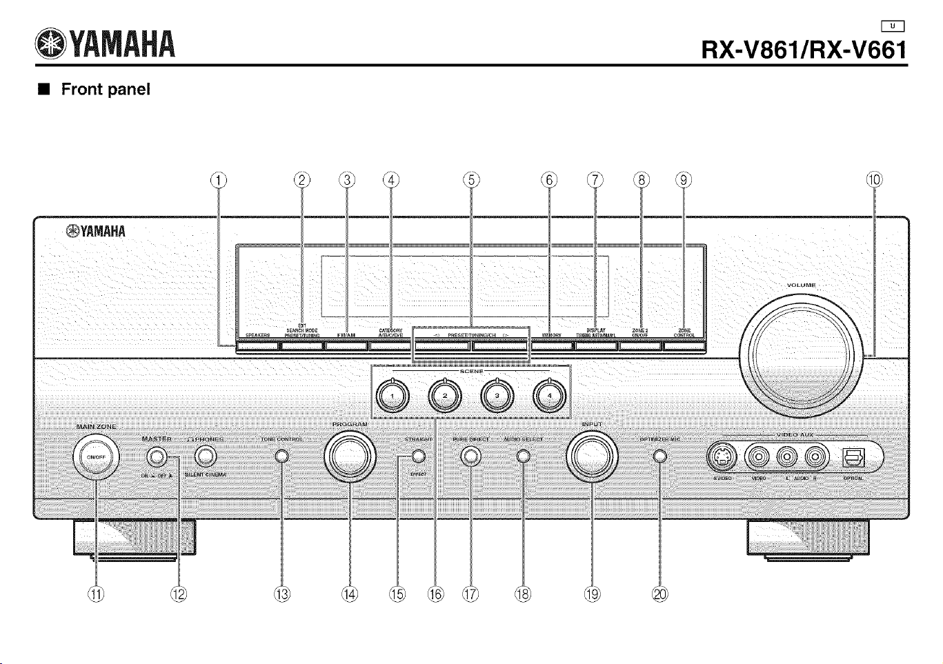
@YAMAHA
• Front panel
RX-V861/RX-V661
®YAMAHA
II J[ Jill J __
=
• Remote control
@
@
CLASSICAL UVE/CLUB ENTERTAIN MOVIE
STEREO_ E H_ERISTRAIGNT
NIGHT
YAMAHA CORPORATION
Printed in Malaysia C WK14480
@YAMAHA
RX-V661
Page 35 (footnote *2)
Incorrect
'2 You can selecl "V-AUX" as the input source even if your iPod is stationed in the Yamaha Universal Dock connected to this
unit. When the SCENE mode is deactivated and your iPod is stationed in the Yamaha Universal Dock, this unit selects
"DOCK" as the input source automatically.
Correct
You can select "V-AUX" as the input source even if your iPod is stationed in the Yamaha Universal Dock connected to this
unil.
YAMAHA CO P@ORATION
Printed in Malaysia cc WK52460