OWNER'S MANUAL
RISKOFELECTRICSHOCK
DONOTOPEN
CAUTION: TO REDUCE THE RISK OF
ELECTRIC SHOCK, DO NOT REMOVE
COVER (OR BACK). NO USER-SERVICEABLE
PARTS INSIDE. REFER SERVICING TO
QUALIFIED SERVICE PERSONNEL.
Explanation of Graphical Symbols
The lightning flash with arrowhead symbol,
within an equilateral triangle, is intended to alert
you to the presence of uninsulated "dangerous
voltage" within the product's enclosure that may
be of"sufficient magnitude to constitute a risk of
electric shock to persons.
The exclamation point within an equilateral
triangle is intended to alert you to the presence of
important operating and maintenance (servicing)
instructions in the literature accompanying the
appliance.
WARNING
TO REDUCE THE RISK OF FIRE OR ELECTRIC SHOCK,
DO NOT EXPOSE THIS UNIT TO RAIN OR MOISTURE.
1 Read Instructions -All the safety and operating instructions
should be read before the product is operated.
2 Retain Instructions - The safety and operating instructions
should be retained for future reference.
3 Heed Warnings - All warnings on the product and in the
operating instructions should be adhered to.
4 Follow Instructions - All operating and use instructions
should be followed.
5 Cleaning - Unplug this product from the wall outlet before
cleaning. Do not use liquid cleaners or aerosol cleaners.
Use a damp cloth for cleaning.
6 Attachments - Do not use attachments not recommended
by the product manufacturer as they may cause hazards.
7 Water and Moisture - Do not use this product near water -
for example, near a bath tub, wash bowl, kitchen sink, or
laundry tub; in a wet basement; or near a swimming pool;
and the like.
8 Accessories - Do not place this product on an unstable cart,
stand, tripod, bracket, or table. The product may fall,
causing serious injury to a child or adult, and serious
damage to the product. Use only with a cart, stand, tripod,
bracket, or table recommended by the manufacturer, or sold
with the product. Any mounting of the product should
follow the manufacturer's instructions, and should use a
mounting accessory recommended by the manufacturer.
A product and cart combination should be
moved with care. Quick stops, excessive
force, and uneven surfaces may cause the
product and cart combination to overturn.
10 Ventilation - Slots and openings in the cabinet are provided
for ventilation and to ensure reliable operation of the
product and to protect it from overheating, and these
openings must not be blocked or covered. The openings
should never be blocked by placing the product on a bed,
sofa, rug, or other similar surface. This product should not
be placed in a built-in installation such as a bookcase or
rack unless proper ventilation is provided or the
manufacturer's instructions have been adhered to.
11 Power Sources - This product should be operated only from
the type of power source indicated on the marking label. If
you are not sure of the type of power supply to your home,
consult your product dealer or local power company. For
products intended to operate from battery power, or other
sources, refer to the operating instructions.
12 Grounding or Polarization - This product may be equipped
with a polarized alternating current line plug (a plug having
one blade wider than the other). This plug will fit into the
power outlet only one way. This is a safety feature. If you
are unable to insert the plug fully into the outlet, try
reversing the plug. If the plug should still fail to fit, contact
your electrician to replace your obsolete outlet. Do not
defeat the safety purpose of the polarized plug.
13 Power-Cord Protection - Power-supply cords should be
routed so that they are not likely to be walked on or pinched
by items placed upon or against them, paying particular
attention to cords at plugs, convenience receptacles, and the
point where they exit from the product.
14 Lightning - For added protection for this product during a
lightning storm, or when it is left unattended and unused for
long periods of time, unplug it from the wall outlet and
disconnect the antenna or cable system. This will prevent
damage to the product due to lightning and powerqine
surges.
15 Power Lines - An outside antenna system should not be
located in the vicinity of overhead power lines or other
electric light or power circuits, or where it can fall into such
power lines or circuits. When installing an outside antenna
system, extreme care should be taken to keep from touching
such power lines or circuits as contact with them might be
fatal.
16 Overloading - Do not overload wall outlets, extension
cords, or integral convenience receptacles as this can result
in a risk of fire or electric shock.
17 Object and Liquid Entry - Never push objects of any kind
into this product through openings as they may touch
dangerous voltage points or short-out parts that could result
in a fire or electric shock. Never spill liquid of any kind on
the product.
18 Servicing - Do not attempt to service this product yourself
as opening or removing covers may expose you to
dangerous voltage or other hazards. Refer all servicing to
qualified service personnel.
19 Damage Requiring Service - Unplug this product from the
wall outlet and refer servicing to qualified service personnel
under the following conditions:
a) When the power-supply cord or plug is damaged,
b) If liquid has been spilled, or objects have fallen into
the product,
c) If the product has been exposed to rain or water,
ICAUTION
d) If the product does not operate normally by following
the operating instructions. Adjust only those controls
that are covered by the operating instructions as an
improper adjustment of other controls may result in
damage and will often require extensive work by a
qualified technician to restore the product to its
normal operation,
e) If the product has been dropped or damaged in any
way, and
OWhen the product exhibits a distinct change in
performance - this indicates a need for service.
20 Replacement Parts -When replacement parts are
required, be sure the service technician has used
replacement parts specified by the manufacturer or have
the same characteristics as the original part.
Unauthorized substitutions may result in fire, electric
shock, or other hazards.
21 Safety Check - Upon completion of any service or
repairs to this product, ask the service technician to
perform safety checks to determine that the product is in
proper operating condition.
22 Wall or Ceiling Mounting - The unit should be mounted
to a wall or ceiling only as recommended by the
manufacturer.
23 Heat - The product should be situated away from heat
sources such as radiators, heat registers, stoves, or other
products (including amplifiers) that produce heat.
Note to CATV system installer:
This reminder is provided to call the CATV system
installer's attention to Article 820-40 of the NEC that
provides guidelines for proper grounding and, in particular,
specifies that the cable ground shall be connected to the
grounding system of the building, as close to the point of
cable entry as practical.
24
___,T__'JIAVk'#lgtlle_'4i[elAvl¢
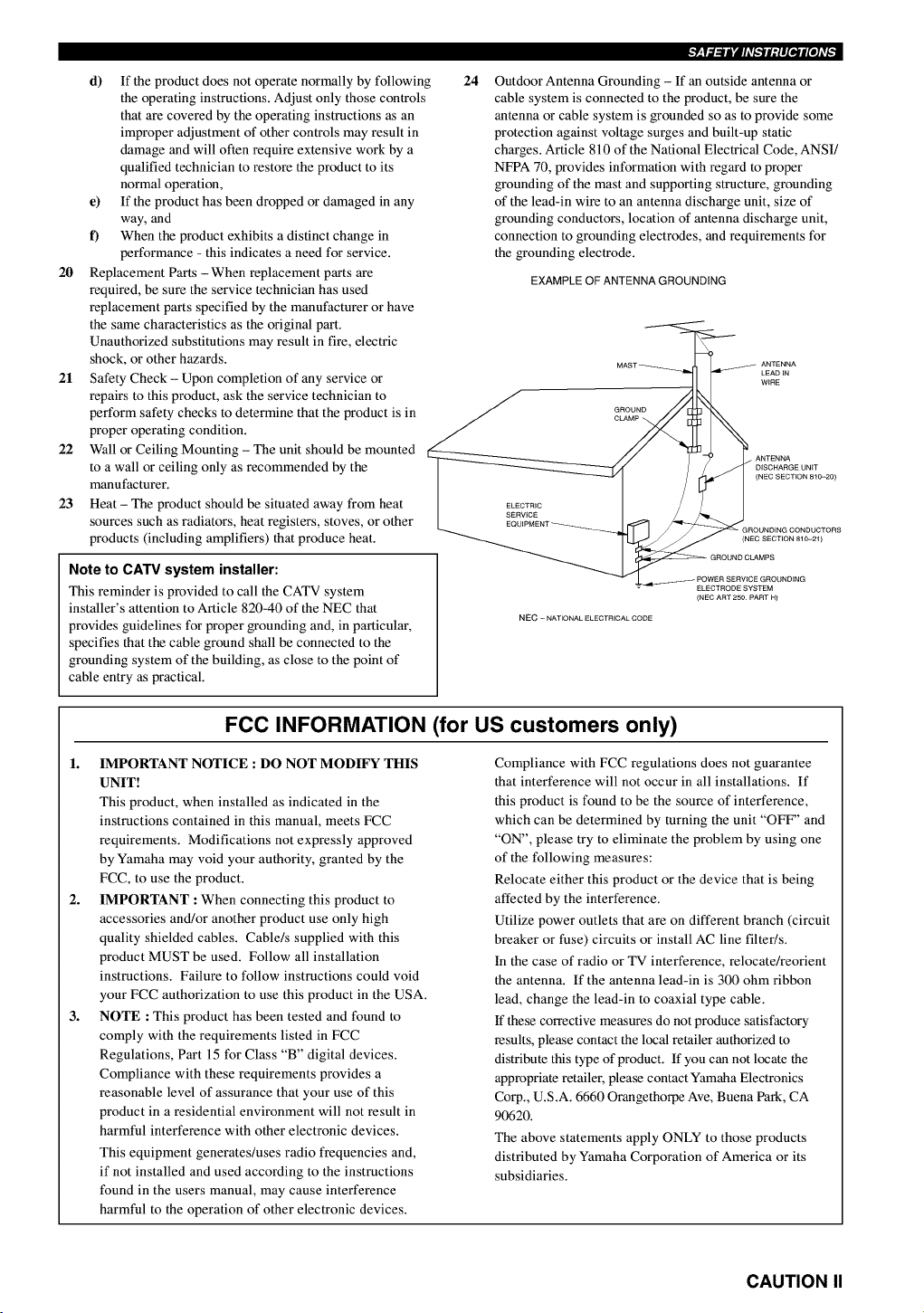
Outdoor Antenna Grounding - If an outside antenna or
cable system is connected to the product, be sure the
antenna or cable system is grounded so as to provide some
protection against voltage surges and built-up static
charges. Article 810 of the National Electrical Code, ANSI/
NFPA 70, provides information with regard to proper
grounding of the mast and supporting structure, grounding
of the lead-in wire to an antenna discharge unit, size of
grounding conductors, location of antenna discharge unit,
connection to grounding electrodes, and requirements for
the grounding electrode.
EXAMPLE OF ANTENNA GROUNDING
GROUND
CLAMP _,
ANTENNA
LEAD JN
WiRE
ELECTRIC
SERVICE
DISCHARGE UNiT
(NEC SECTION 810-20)
(NEC SECTION 810-21)
NEC -NATIONAL ELECTRICAL CODE
ELECTRODE SYSTEM
(NEC ART 250 PART H)
FOG INFORMATION (for US customers only)
1. IMPORTANT NOTICE : DO NOT MODIFY THIS
UNIT!
This product, when installed as indicated in the
instructions contained in this manual, meets FCC
requirements. Modifications not expressly approved
by Yamaha may void your authority, granted by the
FCC, to use the product.
2. IMPORTANT :When connecting this product to
accessories and/or another product use only high
quality shielded cables. Cable/s supplied with this
product MUST be used. Follow all installation
instructions. Failure to follow instructions could void
your FCC authorization to use this product in the USA.
3. NOTE :This product has been tested and found to
comply with the requirements listed in FCC
Regulations, Part 15 for Class "B" digital devices.
Compliance with these requirements provides a
reasonable level of assurance that your use of this
product in a residential environment will not result in
harmful interference with other electronic devices.
This equipment generates/uses radio frequencies and,
if not installed and used according to the instructions
found in the users manual, may cause interference
harmful to the operation of other electronic devices.
Compliance with FCC regulations does not guarantee
that interference will not occur in all installations. If
this product is found to be the source of interference,
which can be determined by turning the unit "OFF" and
"ON", please try to eliminate the problem by using one
of the following measures:
Relocate either this product or the device that is being
affected by the interference.
Utilize power outlets that are on different branch (circuit
breaker or fuse) circuits or install AC line filter/s.
In the case of radio or TV interference, relocate/reorient
the antenna. If the antenna lead-in is 300 ohm ribbon
lead, change the lead-in to coaxial type cable.
If these corrective measures do not produce satisfactory
results, please contact the local retailer authorized to
distribute this type of product. If you can not locate the
appropriate retailer, please contact Yamaha Electronics
Corp., U.S.A. 6660 Orangethorpe Ave, Buena Park, CA
90620.
The above statements apply ONLY to those products
distributed by Yamaha Corporation of America or its
subsidiaries.
CAUTION II
1 To assure the finest performance, please read this
manual carefully. Keep it in a safe place for future
reference.
2 Install this unit in a well ventilated, cool, dry, clean
place with at least 30 cm on the top, 20 cm on the
left and right, and 10 cm at the back of this unit
-- away from direct sunlight, heat sources,
vibration, dust, moisture, and/or cold.
3 Locate this unit away from other electrical
appliances, motors, or transformers to avoid
humming sounds. To prevent fire or electrical
shock, do not place this unit where it may get
exposed to rain, water, and/or any type of liquid.
4 Do not expose this unit to sudden temperature
changes from cold to hot, and do not locate this
unit in a environment with high humidity (i.e. a room
with a humidifier) to prevent condensation inside
this unit, which may cause an electrical shock, fire,
damage to this unit, and/or personal injury.
5 On the top of this unit, do not place:
- Other components, as they may cause damage
and/or discoloration on the surface of this unit.
- Burning objects (i.e. candles), as they may cause
fire, damage to this unit, and/or personal injury.
- Containers with liquid in them, as they may
cause electrical shock to the user and/or
damage to this unit.
6 Do not cover this unit with a newspaper,
tablecloth, curtain, etc. in order not to obstruct
heat radiation. If the temperature inside this unit
rises, it may cause fire, damage to this unit, and/or
personal injury.
7 Do not plug in this unit to a wall outlet until all
connections are complete.
8 Do not operate this unit upside-down. It may
overheat, possibly causing damage.
9 Do not use force on switches, knobs and/or cords.
10 When disconnecting the power cord from the wall
outlet, grasp the plug; do not pull the cord.
11 Do not clean this unit with chemical solvents; this
might damage the finish. Use a clean, dry cloth.
12 Only voltage specified on this unit must be used.
Using this unit with a higher voltage than
specified is dangerous and may cause fire,
damage to this unit, and/or personal injury.
YAMAHA will not be held responsible for any
damage resulting from use of this unit with a
voltage other than specified.
13 To prevent damage by lightning, disconnect the
power cord from the wall outlet during an
electrical storm.
14 Take care of this unit so that no foreign objects
and/or liquid drops inside this unit.
15 Do not attempt to modify or fix this unit. Contact
qualified YAMAHA service personnel when any
service is needed. The cabinet should never be
opened for any reasons.
16 When not planning to use this unit for long
periods of time (i.e. vacation), disconnect the AC
power plug from the wall outlet.
17 Be sure to read the "TROUBLESHOOTING" section
on common operating errors before concluding
that this unit is faulty.
18 Before moving this unit, press STANDBY/ON to set
this unit in the standby mode, and disconnect the
AC power plug from the wall outlet.
19 VOLTAGE SELECTOR (China and General models
only)
The VOLTAGE SELECTOR on the rear panel of this
unit must be set for your local main voltage
BEFORE plugging into the AC main supply.
Voltages are 110/120/220/240 V AC, 50/60 Hz.
This unit is not disconnected from the AC power
source as long as it is connected to the wall outlet,
even if this unit itself is turned off. This state is called
the standby mode. In this state, this unit is designed to
consume a very small quantity of power.
IMPORTANT
Please record the serial number of this unit in the
space below.
MODEL:
Serial No.:
The serial number is located on the rear of the unit.
Retain this Owner's Manual in a safe place for future
reference.
FOR CANADIAN CUSTOMERS
To prevent electric shock, match wide blade of plug to
wide slot and fully insert.
This Class B digital apparatus complies with Canadian
ICES-003.
We Want You Listening For A Lifetime
YAMAHA and the Electronic Industries Association's Consumer
Electronics Group want you to get the most out of your equipment
by playing it at a safe level. One that lets the sound come through
loud and clear without annoying blaring or distortion - and, most
importantly, without affecting your sensitive heating.
Since hearing damage from loud sounds is often
undetectable until it is too late, YAMAHA and the
Electronic Industries Association's Consumer
Electronics Group recommend you to avoid
prolonged exposure from excessive volume levels, r.l_lil_l.l_,=,_
III CAUTION
CONTENTS ............................................................ 1
FEATURES ............................................................. 2
GETTING STARTED ............................................ 3
Checking the package contents ................................. 3
Installing batteries in the remote control ................... 3
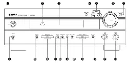
CONTROLS AND FUNCTIONS ......................... 4
Front panel ................................................................ 4
Remote control .......................................................... 6
Using the remote control ........................................... 7
Front panel display .................................................... 8
SPEAKER SETUP ................................................. 9
Speakers .................................................................... 9
Speaker placement .................................................... 9
Connecting the speakers .......................................... 10
CONNECTIONS .................................................. 13
Before connecting components ............................... 13
Connecting video components ................................ 14
Connecting audio components ................................ 16
Connecting the antennas ......................................... 17
Connecting an external decoder .............................. 18
Connecting the power supply cords ........................ 18
Turning on the power .............................................. 19
SPEAKER MODE SETTINGS .......................... 20
ADJUSTING SPEAKER OUTPUT LEVELS .. 21
Using the test tone ................................................... 21
BASIC PLAYBACK ............................................ 23
Input modes and indications .................................... 25
Selecting a sound field program .............................. 26
DIGITAL SOUND FIELD PROCESSING
(DSP) ................................................................. 29
Understanding sound fields ..................................... 29
Hi-Fi DSP programs ................................................ 29
CINEMA-DSP ...................................................... 30
Sound design of CINEMA-DSP ............................. 30
CINEMA-DSP programs ........................................ 32
TUNING ................................................................ 34
Automatic and manual tuning ................................. 34
Presetting stations .................................................... 35
Tuning in to a preset station .................................... 37
Exchanging preset stations ...................................... 37
SLEEP TIMER ..................................................... 38
Setting the sleep timer ............................................. 38
Canceling the sleep timer ........................................ 38
RECORDING ....................................................... 39
SET MENU ........................................................... 40
Adjusting the items on the SET MENU .................. 40
1 SPEAKER SET (speaker mode settings) ............ 41
2LFE LEVEL ........................................................ 43
3 SP DLY TIME (speaker delay time) ................... 43
4 D. RANGE (dynamic range) ............................... 44
5L/R BALANCE (balance of the main left and
right speakers) ..................................................... 44
6 HP TONE CTRL (headphone tone control) ........ 44
7 I/O ASSIGN (input/output assignment) .............. 44
8INPUT MODE (initial input mode) .................... 45
9 DISPLAY SET .................................................... 45
10MEM. GUARD (memory guard) ........................ 45
REMOTE CONTROL FEATURES ................... 46
Control area ............................................................. 46
Setting the manufacturer code ................................. 47
Clearing setup manufacturer codes ......................... 47
Controlling other components ................................. 48
ADJUSTING THE LEVEL OF THE EFFECT
SPEAKERS ....................................................... 49
ADJUSTING THE DELAY TIME ..................... 50
ADJUSTING THE PARAMETER SETTINGS
FOR PRO LOGIC II MUSIC ......................... 51
Changing parameter settings ................................... 51
PRO LOGIC II Music parameter descriptions ....... 51
TROUBLESHOOTING ...................................... 52
GLOSSARY .......................................................... 56
SPECIFICATIONS .............................................. 58
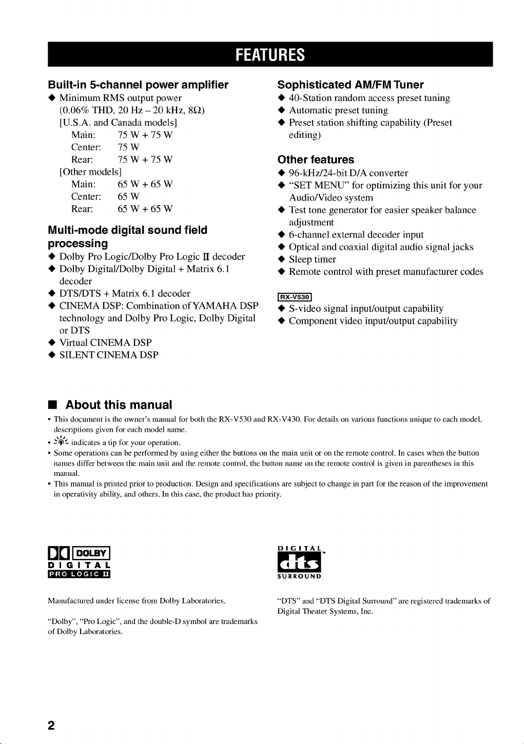
Built-in 5-channel power amplifier
• Minimum RMS output power
(0.06% THD, 20 Hz - 20 kHz, 8_2)
[U.S.A. and Canada modelsl
Main: 75 W + 75 W
Center: 75 W
Rear: 75 W + 75 W
[Other modelsl
Main: 65 W + 65 W
Center: 65 W
Rear: 65 W + 65 W
Multi-mode digital sound field
processing
• Dolby Pro Logic/Dolby Pro Logic 11decoder
• Dolby Digital/Dolby Digital + Matrix 6.1
decoder
• DTS/DTS + Matrix 6.1 decoder
• CINEMA DSP: Combination of YAMAHA DSP
technology and Dolby Pro Logic, Dolby Digital
or DTS
• Virtual CINEMA DSP
• SILENT CINEMA DSP
Sophisticated AM/FM Tuner
• 40-Station random access preset tuning
• Automatic preset tuning
• Preset station shifting capability (Preset
editing)
Other features
• 96-kHz/24-bit D/A converter
• "SET MENU" for optimizing this unit for your
Audio/Video system
• Test tone generator for easier speaker balance
adjustment
• 6-channel external decoder input
• Optical and coaxial digital audio signal jacks
• Sleep timer
• Remote control with preset manufacturer codes
• S-video signal input/output capability
• Component video input/output capability
• About this manual
• This document is the owner's manual for both the RX-V530 and RX-V430. For details on various functions unique to each model,
descriptions given for each model name.
• --"@"-indicates a tip for your operation.
• Some operations can be performed by using either the buttons on the main unit or on the remote control. In cases when the button
names differ between the main unit and the remote control, the button name on the remote control is given in parentheses in this
manual.
• This manual is printed prior to production. Design and specifications are subject to change in part for the reason of the improvement
in operativity ability, and others. In this case, the product has priority.
D0_ DIGIT AL
DIGITAL
Manufactured under license from Dolby Laboratories.
"Dolby", "Pro Logic", and the double-D symbol are trademarks
of Dolby Laboratories.
SURROUND
"DTS" and "DTS Digital Surround" are registered trademarks of
Digital Theater Systems, Inc.
2
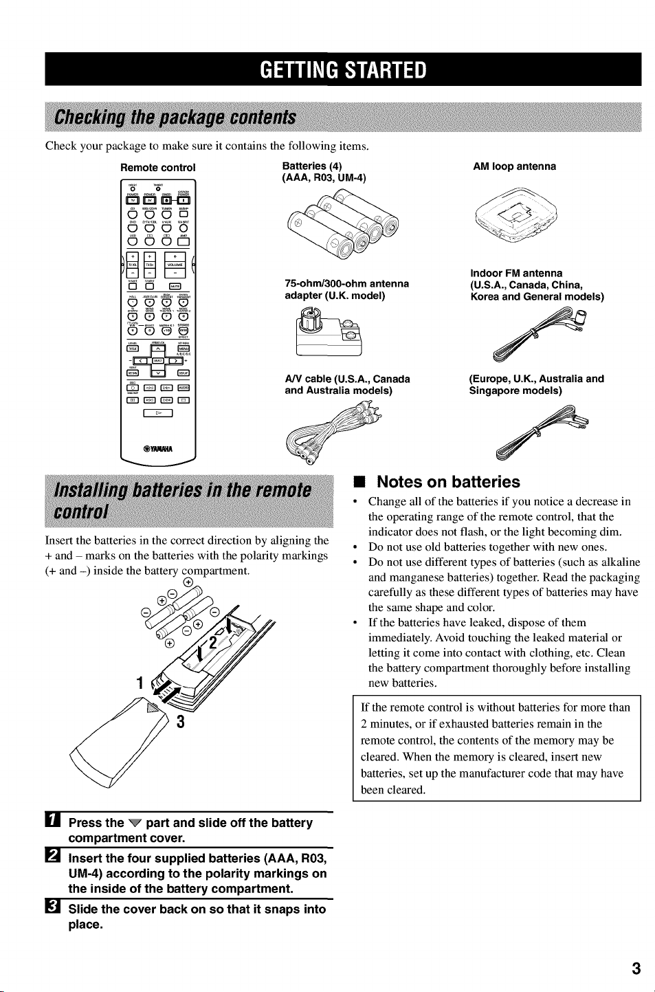
Check your package to make sure it contains the following items.
Remote control
O0_DO
O00Pl
_C90_
Batteries (4)
(AAA, R03, ua-4)
75-ohm/300-ohm antenna
adapter (U.K. model)
A/V cable (U.S.A., Canada
and Australia models)
Insert the batteries in the correct direction by aligning the
+ and - marks on the batteries with the polarity markings
(+ and -) inside the battery
AM loop antenna
Indoor FM antenna
(U.S.A., Canada, China,
Korea and General models)
(Europe, U.K., Australia and
Singapore models)
•Notes on batteries
• Change all of the batteries if you notice a decrease in
the operating range of the remote control, that the
indicator does not flash, or the light becoming dim.
° Do not use old batteries together with new ones.
° Do not use different types of batteries (such as alkaline
and manganese batteries) together. Read the packaging
carefully as these different types of batteries may have
the same shape and color.
° If the batteries have leaked, dispose of them
immediately. Avoid touching the leaked material or
letting it come into contact with clothing, etc. Clean
the battery compartment thoroughly before installing
new batteries.
If the remote control is without batteries for more than
2 minutes, or if exhausted batteries remain in the
remote control, the contents of the memory may be
cleared. When the memory is cleared, insert new
batteries, set up the manufacturer code that may have
been cleared.
[] Press the _part and slide off the battery
compartment cover.
[] Insert the four supplied batteries (AAA, R03,
UM-4) according to the polarity markings on
the inside of the battery compartment.
Slide the cover back on so that it snaps into
place.
3
ql
]
_S_NT
SWn_O
, ,I
8_s
L
U
T_ESL_
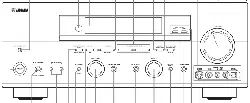
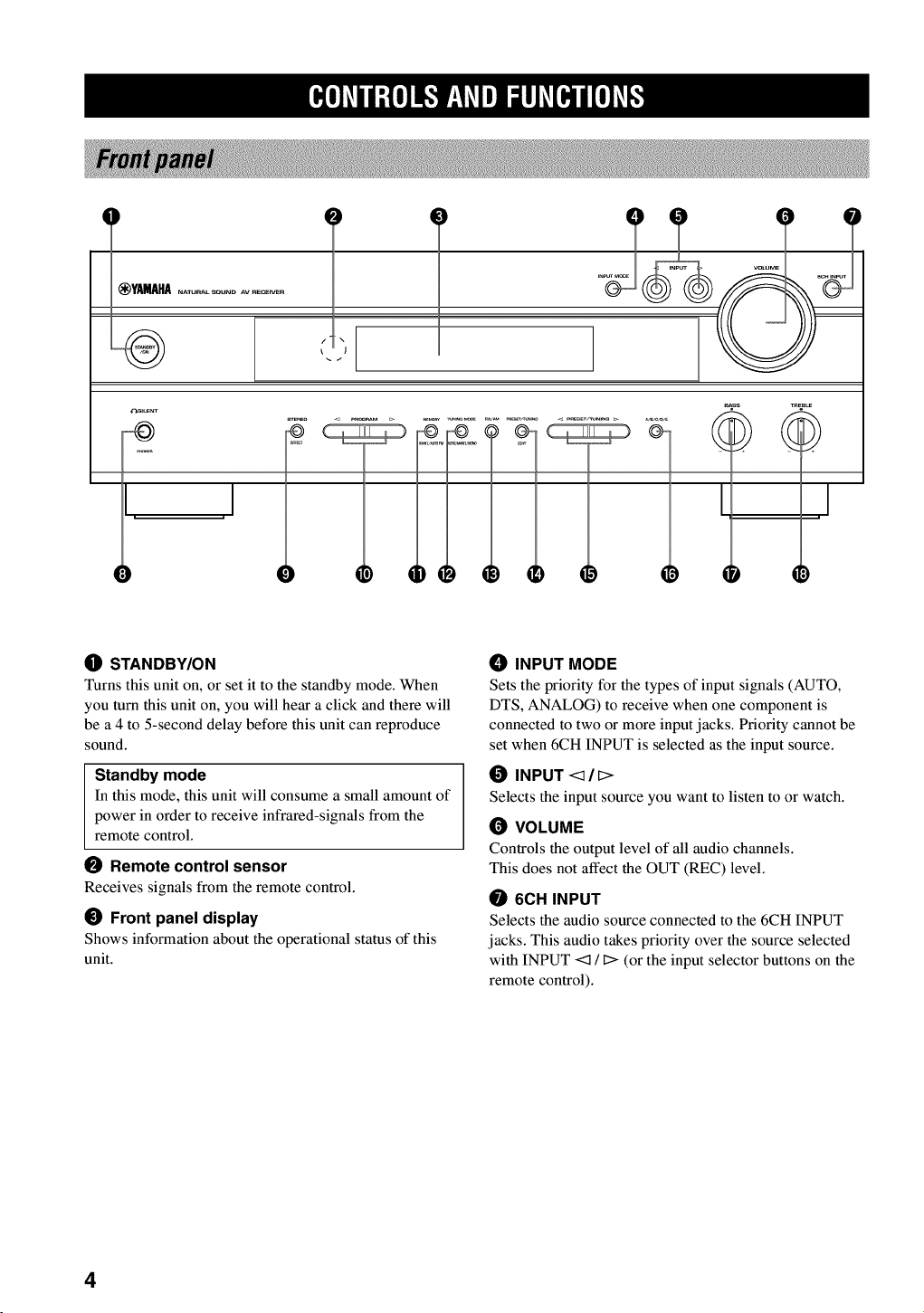
OSTANDBY/ON
Turns this unit on, or set it to the standby mode. When
you turn this unit on, you will hear a click and there will
be a 4 to 5-second delay before this unit can reproduce
sound.
Standby mode
In this mode, this unit will consume a small amount of
power in order to receive infrared-signals from the
remote control.
Remote control sensor
Receives signals from the remote control.
_) Front panel display
Shows information about the operational status of this
unit.
_) INPUT MODE
Sets the priority for the types of input signals (AUTO,
DTS, ANALOG) to receive when one component is
connected to two or more input jacks. Priority cannot be
set when 6CH INPUT is selected as the input source.
INPUT <_/_>
Selects the input source you want to listen to or watch.
(_ VOLUME
Controls the output level of all audio channels.
This does not affect the OUT (REC) level.
6CH INPUT
Selects the audio source connected to the 6CH INPUT
jacks. This audio takes priority over the source selected
with INPUT <1 !D(or the input selector buttons on the
remote control).
4
O _ SILENT (PHONES jack)
Allows you enjoy DSP effect for private listening with
headphones. When you connect headphones, no signals
are output to the speakers.
_) STEREO/EFFECT
Switches between normal stereo and DSP effect
reproduction. When STEREO is selected, 2-channel
signals are directed to the main left and right speakers
without effect sounds and all Dolby Digital and DTS
signals (except the LFE channel) are mixed down to the
main left and fight speakers.
_) PROGRAM <] /[>
Selects the DSP program.
0MEMORY (MAN'L/AUTO FM)
Stores the current station in the memory.
_) TUNING MODE (AUTO/MAN'L MONO)
Switches the tuning mode between automatic and manual.
_) FM/AM
Switches the reception band between FM and AM.
_) PRESET/TUNING (EDIT)
Switches the function of PRESET/TUNING <1 /C>
between selecting a preset station number and tuning (the
colon (:) turns on or off).
This button is also used to exchange the assignment of
two preset stations with each other.
_) PRESET/TUNING <:]/_>
Selects preset station numbers 1 to 8 when the colon (:)
appears in the front panel display.
Selects the tuning frequency when the colon (:) does not
appear.
@A/B/C/D/E
Selects preset station groups A to E.
,_m]Avlltr,{e]l_,"f_,yAVlll=71hV[Bjrl[e]Av_
(]_ BASS
Adjusts the low-frequency response for the main left and
right channels.
Turn fight to increase or turn left to decrease the low-
frequency response.
_) TREBLE
Adjusts the high-frequency response for the main left and
right channels.
Turn fight to increase or turn left to decrease the high-
frequency response.
5
mMo]Avlt_fo]lF.IP_,YAVl_i_lh_[_l[o]Av[_
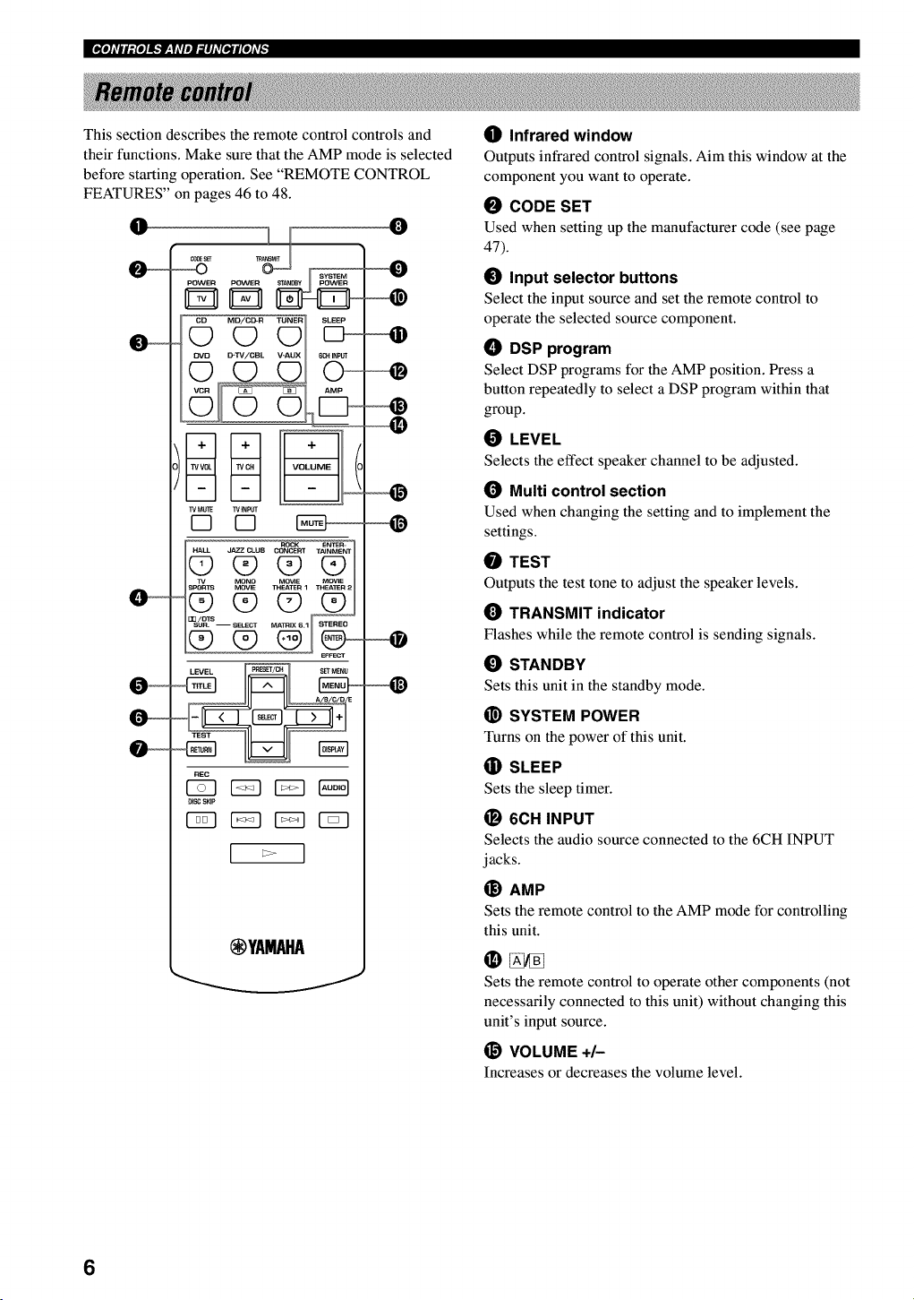
This section describes the remote control controls and
their functions. Make sure that the AMP mode is selected
before starting operation. See "REMOTE CONTROL
FEATURES" on pages 46 to 48.
O
__
,_T O_ SyBTEM
Q
TV M_E TVNPUT
ROCK ENTEn-
1v MONO MOVIE MOWE
_ i_1
REC
DISC SKIP
(_YAMAHA
0
_]) Infrared window
Outputs infrared control signals. Aim this window at the
component you want to operate.
0CODE SET
Used when setting up the manufacturer code (see page
47).
_) Input selector buttons
Select the input source and set the remote control to
operate the selected source component.
ODSP program
Select DSP programs for the AMP position. Press a
button repeatedly to select a DSP program within that
group.
0LEVEL
Selects the effect speaker channel to be adjusted.
(_ Multi control section
Used when changing the setting and to implement the
settings.
0TEST
Outputs the test tone to adjust the speaker levels.
TRANSMIT indicator
Flashes while the remote control is sending signals.
_) STANDBY
Sets this unit in the standby mode.
_) SYSTEM POWER
Turns on the power of this unit.
(]i) SLEEP
Sets the sleep timer.
_) 6ell INPUT
Selects the audio source connected to the 6CH INPUT
jacks.
_) AMP
Sets the remote control to the AMP mode for controlling
this unit.
Sets the remote control to operate other components (not
necessarily connected to this unit) without changing this
unit's input source.
@ VOLUME +/-
Increases or decreases the volume level.
6
_) MUTE
Mutes the sound. Press again to restore the audio output
to the previous volume level.
O STEREO/EFFECT
Switches between normal stereo and DSP effect
reproduction. When STEREO is selected, 2-channel
signals are directed to the main left and right speakers
without effect sounds and all Dolby Digital and DTS
signals (except the LFE channel) are mixed down to the
main left and fight speakers.
I_) SET MENU
Selects the SET MENU mode.
,gmIAVltt,{ellf,,"f_'yAVlDI._IhV[BJrI[e]AV_
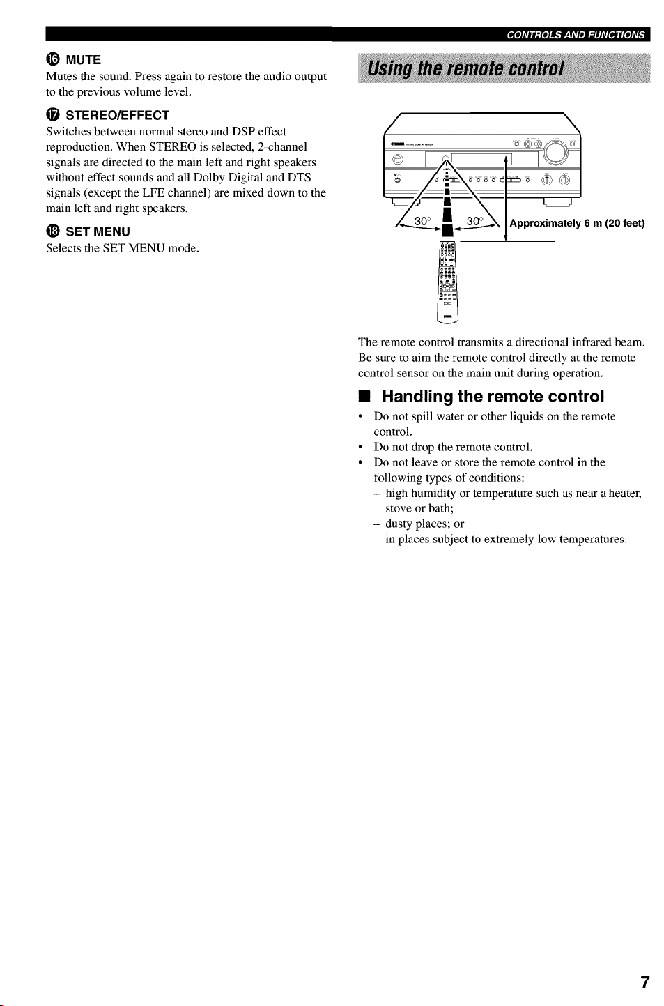
Approximately 6 m (20 feet)
The remote control transmits a directional infrared beam.
Be sure to aim the remote control directly at the remote
control sensor on the main unit during operation.
•Handling the remote control
• Do not spill water or other liquids on the remote
control.
• Do not drop the remote control.
• Do not leave or store the remote control in the
following types of conditions:
- high humidity or temperature such as near a heater,
stove or bath;
- dusty places; or
- in places subject to extremely low temperatures.
7
I[gl]#lt:{I]lk'f_Y#lml_]l]#[I,Jl[#]#_
I =x1 ,!vc.j v_Auxo.,v c=,ov°,=ojc ,TUNE.
I_ _I,_TS _BY_O°U]_ ] r_STEREOAUT_EU_pI_EUME
t l S'LENT " t' 12ENTE"TA'NMENTJ I|TUINED MEMORY _'_1_
I_LIN N N N N N N N N N N N N
i======"=="==="====="====="====="="========="=====!!!!!!_ !!!!!!!!!!!!!!!!!!! ============================Ed=
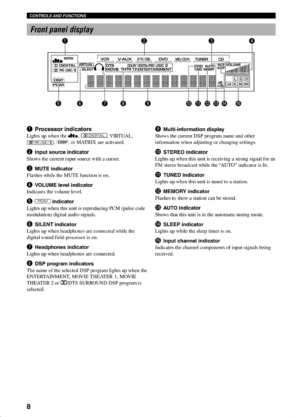
OProcessor indicators
Lights up when the _, (mDIGITAL 1, VIRTUAL,
(nn PROk0GIC/_), _ or MATRIX are activated.
OInput source indicator
Shows the current input source with a cursor.
_) MUTE indicator
Flashes while the MUTE function is on.
_) VOLUME level indicator
Indicates the volume level.
_indicator
Lights up when this unit is reproducing PCM (pulse code
modulation) digital audio signals.
(_ SILENT indicator
Lights up when headphones are connected while the
digital sound field processor is on.
Headphones indicator
Lights up when headphones are connected.
DSP program indicators
The name of the selected DSP program lights up when the
ENTERTAINMENT, MOVIE THEATER 1, MOVIE
THEATER 2 or DI'I/DTS SURROUND DSP program is
selected.
_) Multi-information display
Shows the current DSP program name and other
information when adjusting or changing settings.
_) STEREO indicator
Lights up when this unit is receiving a strong signal for an
FM stereo broadcast while the "AUTO" indicator is lit.
(]i) TUNED indicator
Lights up when this unit is tuned to a station.
MEMORY indicator
Flashes to show a station can be stored.
_) AUTO indicator
Shows that this unit is in the automatic tuning mode.
_) SLEEP indicator
Lights up while the sleep timer is on.
_) Input channel indicator
Indicates the channel components of input signals being
received.
8
This unit has been designed to provide the best sound-
field quality with a 5-speaker system, using main left and
fight speakers, rear left and right speakers and a center
speaker. If you use different brands of speakers (with
different tonal qualities) in your system, the tone of a
moving human voice and other types of sound may not
shift smoothly. We recommend that you use speakers
from the same manufacturer or speakers with the same
tonal quality.
The main speakers are used for the main source sound
plus effect sounds. They will probably be the speakers
from your present stereo system. The rear speakers are
used for effect and surround sounds. The center speaker is
for the center sounds (dialog, vocals, etc.).
The main speakers should be high-performance models
and have enough power-handling capacity to accept the
maximum output of your audio system. The other
speakers do not have to be equal to the main speakers. For
precise sound localization, however, it is ideal to use the
models of equivalent performance with the main
speakers.
•Use of a subwoofer expands your
sound field
It is also possible to further expand your system with the
addition of a subwoofer. The use of a subwoofer is
effective not only for reinforcing bass frequencies from
any or all channels, but also for reproducing the LFE
(low-frequency effect) channel with high fidelity when
playing back Dolby Digital or DTS signals. The
YAMAHA Active Servo Processing Subwoofer System is
ideal for natural and lively bass reproduction.
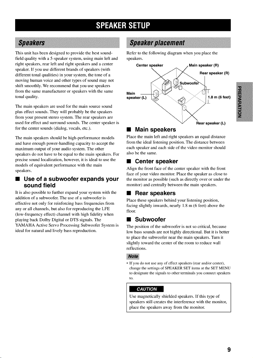
Referto the following diagram when you place the
speakers.
Centerspeaker speaker(R)
Rearspeaker(R)
Main
speaker (L) 1.8 m (6 feet)
/
Rear speaker (L)
•Main speakers
Place the main left and right speakers an equal distance
from the ideal listening position. The distance between
each speaker and each side of the video monitor should
also be the same.
•Center speaker
Align the front face of the center speaker with the front
face of your video monitor. Place the speaker as close to
the monitor as possible (such as directly over or under the
monitor) and centrally between the main speakers.
•Rear speakers
Place these speakers behind your listening position,
facing slightly inwards, nearly 1.8 m (6 feet) above the
floor.
•Subwoofer
The position of the subwoofer is not so critical, because
low bass sounds are not highly directional. But it is better
to place the subwoofer near the main speakers. Turn it
slightly toward the center of the room to reduce wall
reflections.
• If you do not use any of effect speakers (rear and/or center),
change the settings of SPEAKER SET items at the SET MENU
to designate the signals to other terminals you connect speakers
to.
Use magnetically shielded speakers. If this type of
speakers still creates the interference with the monitor,
place the speakers away from the monitor.
9
Ek'!".t=r__YN:1:B.'!_lll]"
Be sure to connect the left channel (L), fight channel (R), "+" (red) and "-" (black) properly. If the connections are
faulty, no sound will be heard from the speakers, and if the polarity of the speaker connections is incorrect, the sound
will be unnatural and lack bass.
•Use speakers with the specified impedance shown on the rear panel of this unit.
° Do not let the bare speaker wires touch each other or any metal part of this unit. This could damage this unit and/
or the speakers.
If necessary, use the SET MENU to change the speaker mode settings according to the number and size of the speakers
in your configuration after you finish connecting your speakers.
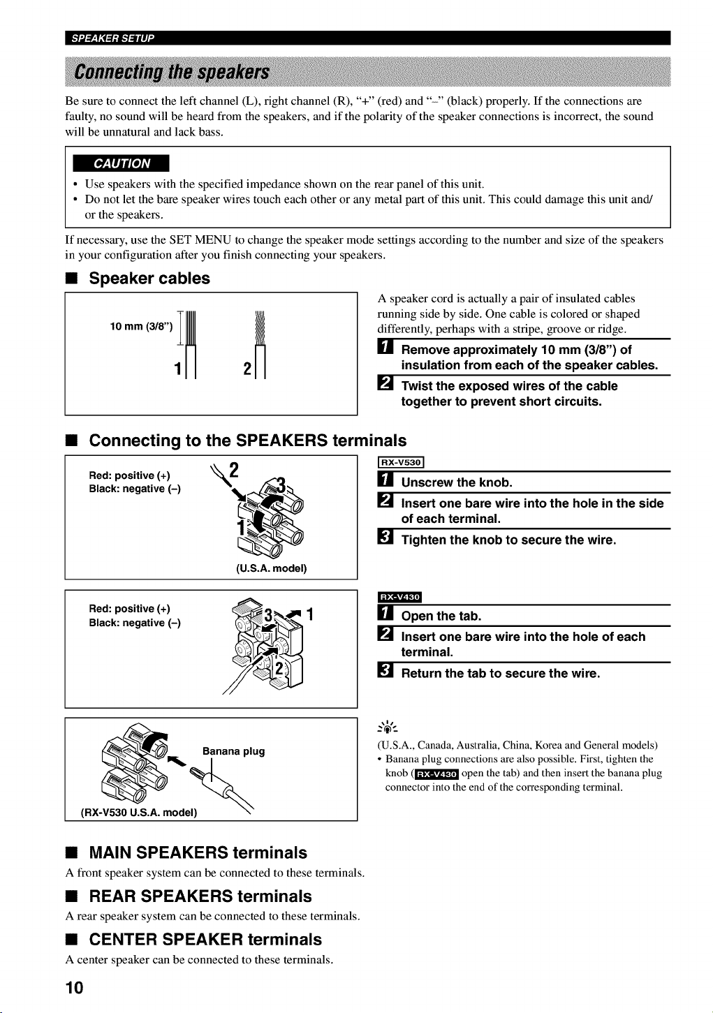
•Speaker cables
A speaker cord is actually a pair of insulated cables
running side by side. One cable is colored or shaped
differently, perhaps with a stripe, groove or ridge.
[] Remove approximately 10 mm (318") of
insulation from each of the speaker cables.
_._ Twist the exposed wires of the cable
together to prevent short circuits.
•Connecting to the SPEAKERS terminals
Red: positive (+) "_L
Black: negative (-)
(U.S.A. model)
[] Unscrew the knob.
_._ Insert one bare wire into the hole in the side
of each terminal.
[] Tighten the knob to secure the wire.
Red: positive (+)
Black: negative (-) [] Open the tab.
P_ Insert one bare wire into the hole of each
terminal.
[] Return the tab to secure the wire.
Banana plug
(RX-V530 U.S.A. model)
(U.S.A., Canada, Australia, China, Korea and General models)
• Banana plug connections are also possible. First, tighten the
knob (1"_!_ open the tab) and then insert the banana plug
connector into the end of the corresponding terminal.
•MAIN SPEAKERS terminals
A front speaker system can be connected to these terminals.
•REAR SPEAKERS terminals
A rear speaker system can be connected to these terminals.
•CENTER SPEAKER terminals
A center speaker can be connected to these terminals.
10
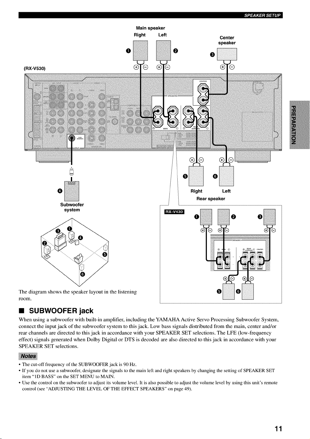
(RX-V530)
Main speaker
Right Left
0 0
Center
speaker
0
®
0
0
Subwoofer
system
The diagram shows the speaker layout in the listening
room.
Right Left
Rearspeaker
• SUBWOOFER jack
When using a subwoofer with built-in amplifier, including the YAMAHA Active Servo Processing Subwoofer System,
connect the input jack of the subwoofer system to this jack. Low bass signals distributed from the main, center and/or
rear channels are directed to this jack in accordance with your SPEAKER SET selections. The LFE (low-frequency
effect) signals generated when Dolby Digital or DTS is decoded are also directed to this jack in accordance with your
SPEAKER SET selections.
• The cut-off frequency of the SUBWOOFER jack is 90 Hz.
• If you do not use a subwoofer, designate the signals to the main left and right speakers by changing the setting of SPEAKER SET
item "ID BASS" on the SET MENU to MAIN.
• Use the control on the subwoofer to adjust its volume level. It is also possible to adjust the volume level by using this unit's remote
control (see "ADJUSTING THE LEVEL OF THE EFFECT SPEAKERS" on page 49).
11
Ek'!".t=rzlN:1:B.'!_lll]"
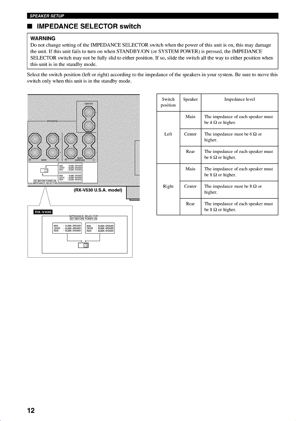
•IMPEDANCE SELECTOR switch
WARNING
Do not change setting of the IMPEDANCE SELECTOR switch when the power of this unit is on, this may damage
the unit. If this unit fails to turn on when STANDBY/ON (or SYSTEM POWER) is pressed, the IMPEDANCE
SELECTOR switch may not be fully slid to either position. If so, slide the switch all the way to either position when
this unit is in the standby mode.
Select the switch position (left or right) according to the impedance of the speakers in your system. Be sure to move this
switch only when this unit is in the standby mode.
(RX-V530 U.S.A. model)
IMPEDANCE SELECTOR
ISET BEFORE POWER ON I
CENTER : 6£_MINSPEAKER CENTER 8£_NIN/SPEAKER
REAR : 6_BdIN _EPEAKER REAR 8_MIN/SPEAKER
[1
Switch Speaker Impedance level
position
Main The impedance of each speaker must
be 4 _ or higher.
Left Center The impedance must be 6 _ or
higher.
Rear The impedance of each speaker must
be 6 _ or higher.
Main The impedance of each speaker must
be 8 _ or higher.
Right Center The impedance must be 8 _ or
higher.
Rear The impedance of each speaker must
be 8 _ or higher.
12
Do not connect this unit or other components to the
mains power until all connections between the
components have been completed.
Be sure all connections are made correctly, that is to
say L (left) to L, R (right) to R, "+" to "+" and "-" to
"-". Some components require different connection
methods and have different jack names. Refer to the
operation instructions for each component to be
connected to this unit.
° When you connect other YAMAHA audio components
(such as a tape deck, MD recorder and CD player or
changer), connect them to the jack with the same
number labels as [_, [_, [] etc. YAMAHA applies this
labeling system to all its products.
° After you have completed all connections, check them
again to make sure they are correct.
° The name of jack corresponds to input selector.
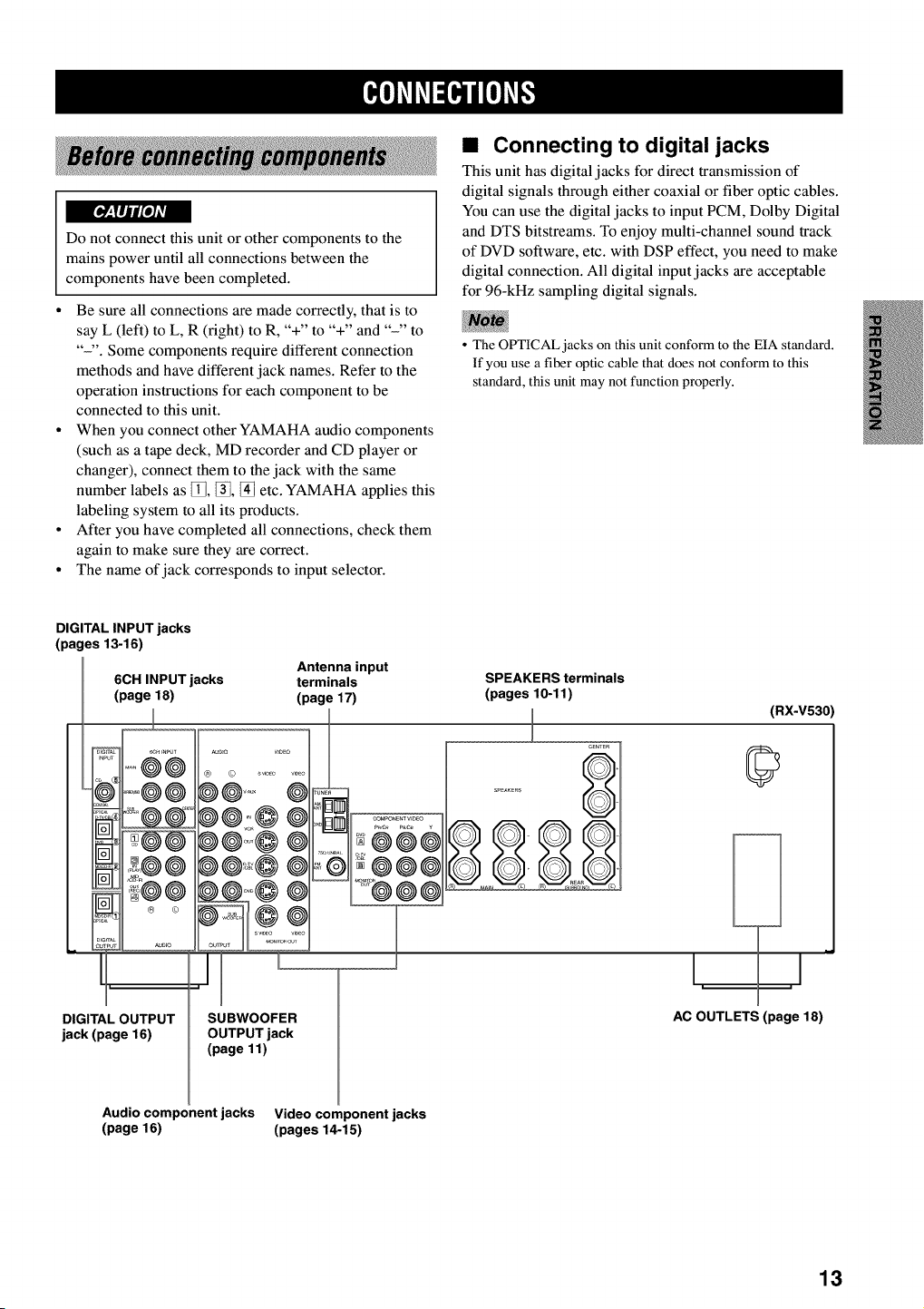
• Connecting to digital jacks
This unit has digital jacks for direct transmission of
digital signals through either coaxial or fiber optic cables.
You can use the digital jacks to input PCM, Dolby Digital
and DTS bitstreams. To enjoy multi-channel sound track
of DVD software, etc. with DSP effect, you need to make
digital connection. All digital input jacks are acceptable
for 96-kHz sampling digital signals.
• The OPTICAL jacks on this unit conform to the EIA standard.
If you use a fiber optic cable that does not conform to this
standard, this unit may not function properly.
DIGITAL INPUT jacks
(pages 13-16)
Antenna input
6CH INPUT jacks terminals
(page 18) (page 17)
== j • _uDio
DIGITAL OUTPUT
jack (page 16)
SPEAKERS terminals
(pages 10-11)
_uD,o V,DEO
@
SUBWOOFER
OUTPUT jack
(page 11)
211 @®e
JCeNTE_
S_EAKERS
(RX-V530)
©
hi
_J
AC OUTLETS (page 18)
Audio component jacks Video component jacks
(page 16) (pages 14-15)
13
I[_i'li'ffl_lNi'F
Refer to the connection examples on the next page.
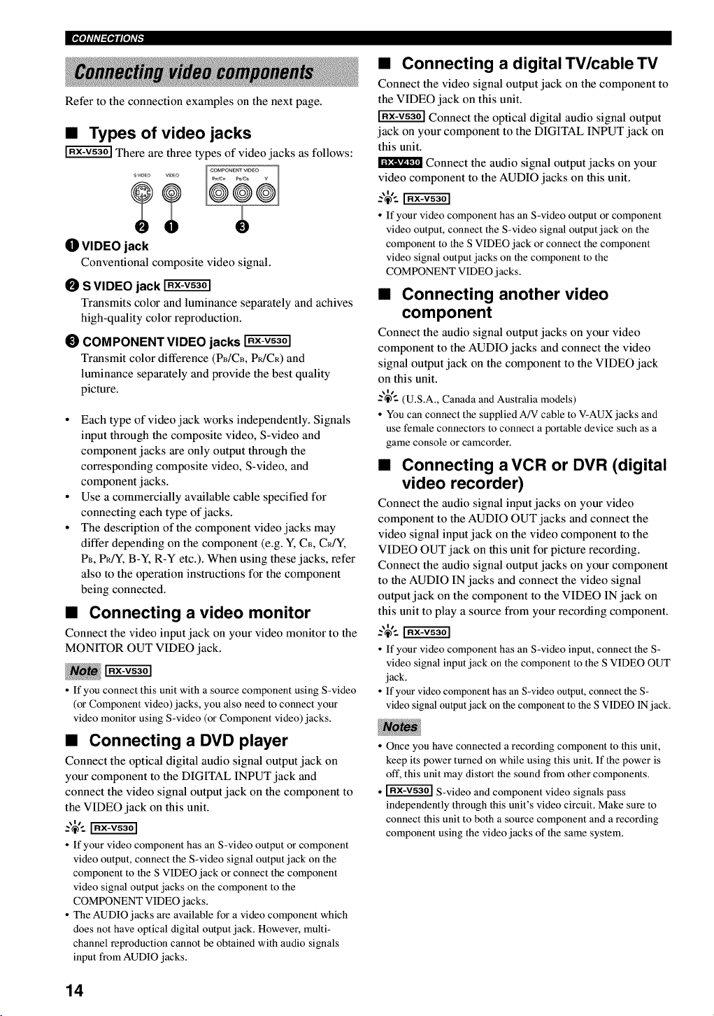
•Types of video jacks
There are three types of video jacks as follows:
OVIDEO jack
Conventional composite video signal.
OS VIDEO jack
Transmits color and luminance separately and achives
high-quality color reproduction.
_) COMPONENT VIDEO jacks
Transmit color difference (PB/CB, P_/CR) and
luminance separately and provide the best quality
picture.
• Each type of video jack works independently. Signals
input through the composite video, S-video and
component jacks are only output through the
corresponding composite video, S-video, and
component jacks.
• Use a commercially available cable specified for
connecting each type of jacks.
• The description of the component video jacks may
differ depending on the component (e.g. Y, C_, CR/Y,
PB, PRfY, B-Y, R-Y etc.). When using these jacks, refer
also to the operation instructions for the component
being connected.
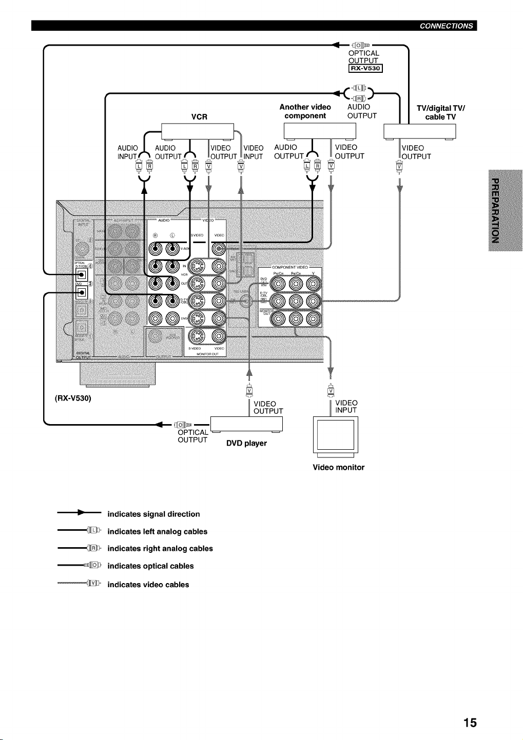
•Connecting a video monitor
Connect the video input jack on your video monitor to the
MONITOR OUT VIDEO jack.
• If you connect this unit with a source component using S-video
(or Component video) jacks, you also need to connect your
video monitor using S-video (or Component video) jacks.
•Connecting a DVD player
Connect the optical digital audio signal output jack on
your component to the DIGITAL INPUT jack and
connect the video signal output jack on the component to
the VIDEO jack on this unit.
• If your video component has an S-video output or component
video output, connect the S-video signal output jack on the
component to the S VIDEO jack or connect the component
video signal output jacks on the component to the
COMPONENT VIDEO jacks.
• The AUDIO jacks are available for a video component which
does not have optical digital output jack. However, multi-
channel reproduction cannot be obtained with audio signals
input from AUDIO jacks.
•Connecting a digital TV/cableTV
Connect the video signal output jack on the component to
the VIDEO jack on this unit.
Connect the optical digital audio signal output
jack on your component to the DIGITAL INPUT jack on
this unit.
Connect the audio signal output jacks on your
video component to the AUDIO jacks on this unit.
• If your video component has an S-video output or component
video output, connect the S-video signal output jack on the
component to the S VIDEO jack or connect the component
video signal output jacks on the component to the
COMPONENT VIDEO jacks.
•Connecting another video
component
Connect the audio signal output jacks on your video
component to the AUDIO jacks and connect the video
signal output jack on the component to the VIDEO jack
on this unit.
-'_'-- (U.S.A., Canada and Australia models)
• You can connect the supplied A/V cable to V-AUX jacks and
use female connectors to connect a portable device such as a
game console or camcorder.
•Connecting a VCR or DVR (digital
video recorder)
Connect the audio signal input jacks on your video
component to the AUDIO OUT jacks and connect the
video signal input jack on the video component to the
VIDEO OUT jack on this unit for picture recording.
Connect the audio signal output jacks on your component
to the AUDIO IN jacks and connect the video signal
output jack on the component to the VIDEO IN jack on
this unit to play a source from your recording component.
• If your video component has an S-video input, connect the S-
video signal input jack on the component to the S VIDEO OUT
jack.
• If your video component has an S-video output, connect the S-
video signal output jack on the component to the S VIDEO IN jack.
• Once you have connected a recording component to this unit,
keep its power turned on while using this unit. If the power is
oft', this unit may distort the sound from other components.
• _ S-video and component video signals pass
independently through this unit's video circuit. Make sure to
connect this unit to both a source component and a recording
component using the video jacks of the same system.
14
_ioli'li'l_iloli'F
OPTICAL
OUTPUT
Another video AUDIO I TV/digital TV/
component OUTPUT I cable TV
I I
AU_ .L v,_o -- VIDEO
OUTPUT_ _ OUTPUT OUTPUT
(RX-V530)
OPTICAL
OUTPUT
VIDEO
OUTPUT
I
DVD player
VlDt
INPt
i i
Video monitor
indicates signal direction
--_ indicates left analog cables
--_= indicates right analog cables
--_ indicates optical cables
'_D= indicates video cables
15
IPiqi'ffl_lNi'F
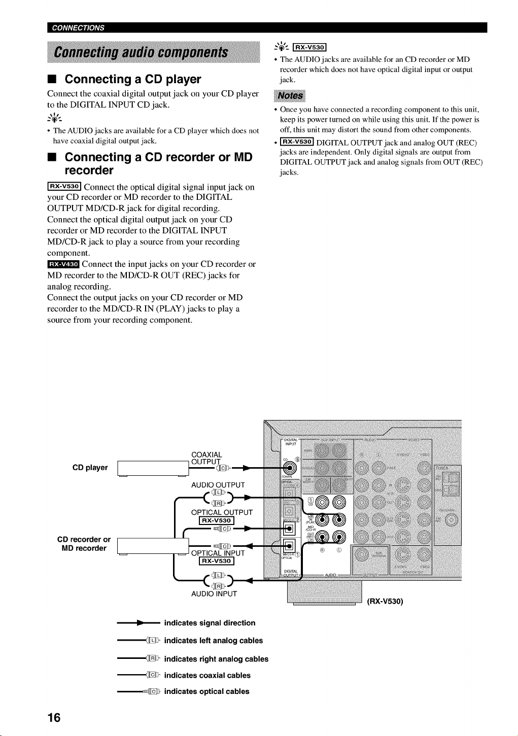
•Connecting a CD player
Connect the coaxial digital output jack on your CD player
to the DIGITAL INPUT CD jack.
• The AUDIO jacks are available for a CD player which does not
have coaxial digital output jack.
•Connecting a CD recorder or MD
recorder
Connect the optical digital signal input jack on
your CD recorder or MD recorder to the DIGITAL
OUTPUT MD/CD-R jack for digital recording.
Connect the optical digital output jack on your CD
recorder or MD recorder to the DIGITAL INPUT
MD/CD-R jack to play a source from your recording
component.
Connect the input jacks on your CD recorder or
MD recorder to the MD/CD-R OUT (REC) jacks for
analog recording.
Connect the output jacks on your CD recorder or MD
recorder to the MD/CD-R IN (PLAY) jacks to play a
source from your recording component.
• The AUDIO jacks are available for an CD recorder or MD
recorder which does not have optical digital input or output
jack.
• Once you have connected a recording component to this unit,
keep its power turned on while using this unit. If the power is
oft', this unit may distort the sound from other components.
• _ DIGITAL OUTPUT jack and analog OUT (REC)
jacks are independent. Only digital signals are output from
DIGITAL OUTPUT jack and analog signals from OUT (REC)
jacks.
CD player [
CD recorder or [
MD recorder /
COAXIAL
OUTPUT
AUDIO OUTPUT
AUDIO INPUT
indicates signal direction
__ indicates left analog cables
__ indicates right analog cables
__ indicates coaxial cables
__ indicates optical cables
(RX-V530)
16
_ioli'ffl_iNi'F
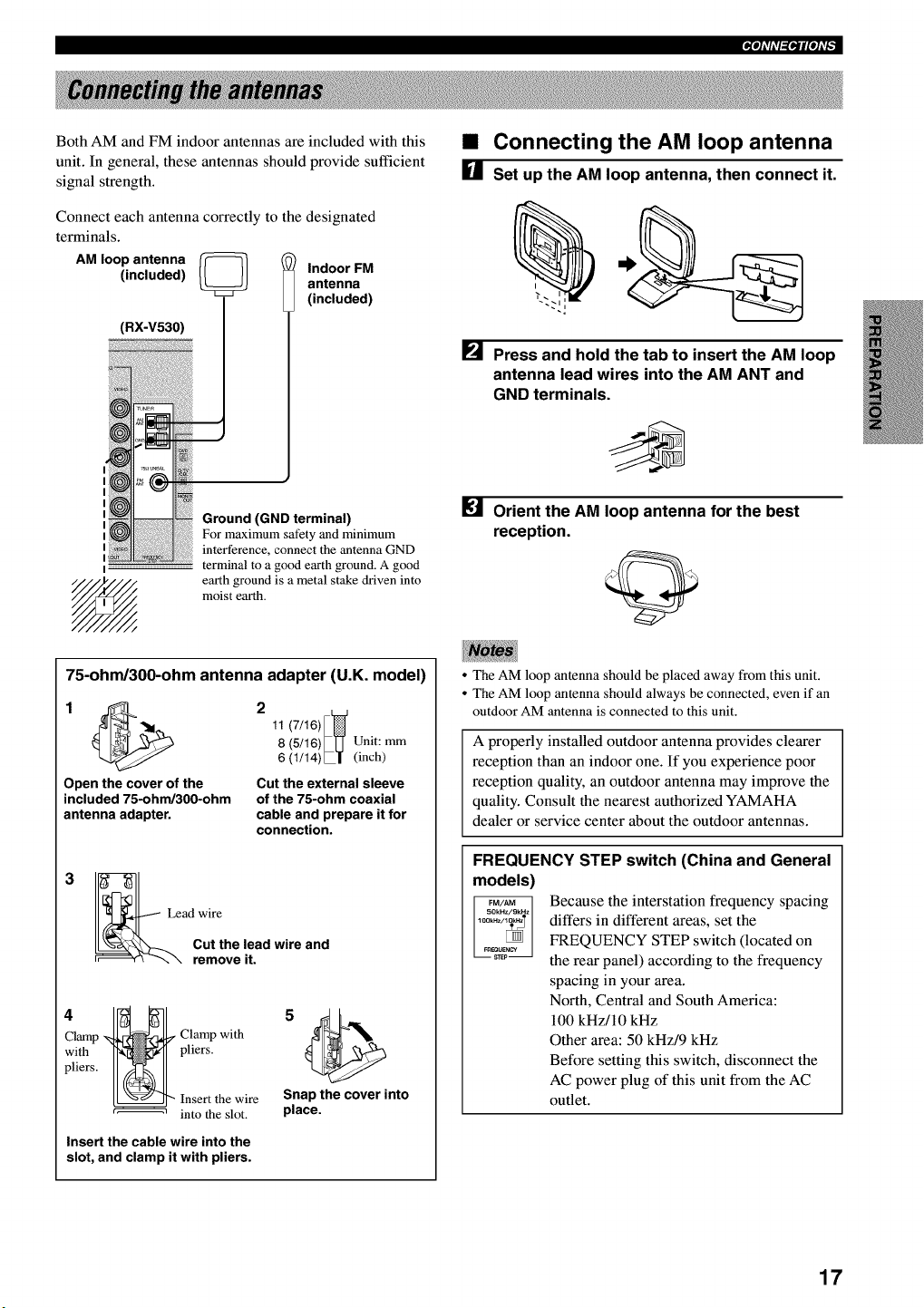
Both AM and FM indoor antennas are included with this
unit. In general, these antennas should provide sufficient
signal strength.
Connect each antenna correctly to the designated
terminals.
AM loop antenna _
(included) Indoor FM
antenna
(included)
(RX-V530)
I
Ground (GND terminal)
For maximum safety and minimum
interference, connect the antenna GND
terminal to a good earth ground. A good
earth ground is a metal stake driven into
moist earth.
•Connecting the AM loop antenna
[] Set up the AM loop antenna, then connect it.
i
[] Press and hold the tab to insert the AM loop
antenna lead wires into the AM ANT and
GND terminals.
Orient the AM loop antenna for the best
reception.
75-ohm/300-ohm antenna adapter (U.K. model)
11 (7/16)
8 (5/16)_LJ Unit: mm
6 (1/14)L| (inch)
Open the cover of the Cut the external sleeve
included 75-ohm/300-ohm of the 75-ohm coaxial
antenna adapter, cable and prepare it for
connection.
3
Lead wire
Cut the lead wire and
remove it.
Clamp _ Clamp with
with H-_ pliers.
p.ersI1 1
I_22 r_hehel_t!re
Insert the cable wire into the
slot, and clamp it with pliers.
Snap the cover into
place.
• The AM loop antenna should be placed away from this unit.
• The AM loop antenna should always be connected, even if an
outdoor AM antenna is connected to this unit.
A properly installed outdoor antenna provides clearer
reception than an indoor one. If you experience poor
reception quality, an outdoor antenna may improve the
quality. Consult the nearest authorized YAMAHA
dealer or service center about the outdoor antennas.
FREQUENCY STEP switch (China and General
models)
Because the interstation frequency spacing
differs in different areas, set the
FREQUENCY STEP switch (located on
the rear panel) according to the frequency
spacing in your area.
North, Central and South America:
100 kHz/10 kHz
Other area: 50 kHz/9 kHz
Before setting this switch, disconnect the
AC power plug of this unit from the AC
outlet.
17
IPi'li'ffl_li'li'F
This unit is equipped with 6 additional input jacks (MAIN
left and right, CENTER, SURROUND left and fight and
SUBWOOFER) for discrete multi-channel input from an
external decoder, sound processor, or pre-amplifier.
Connect the output jacks on your external decoder to the
6CH INPUT jacks. Be sure to match the left and fight
outputs to the left and fight input jacks for the main and
surround channels.
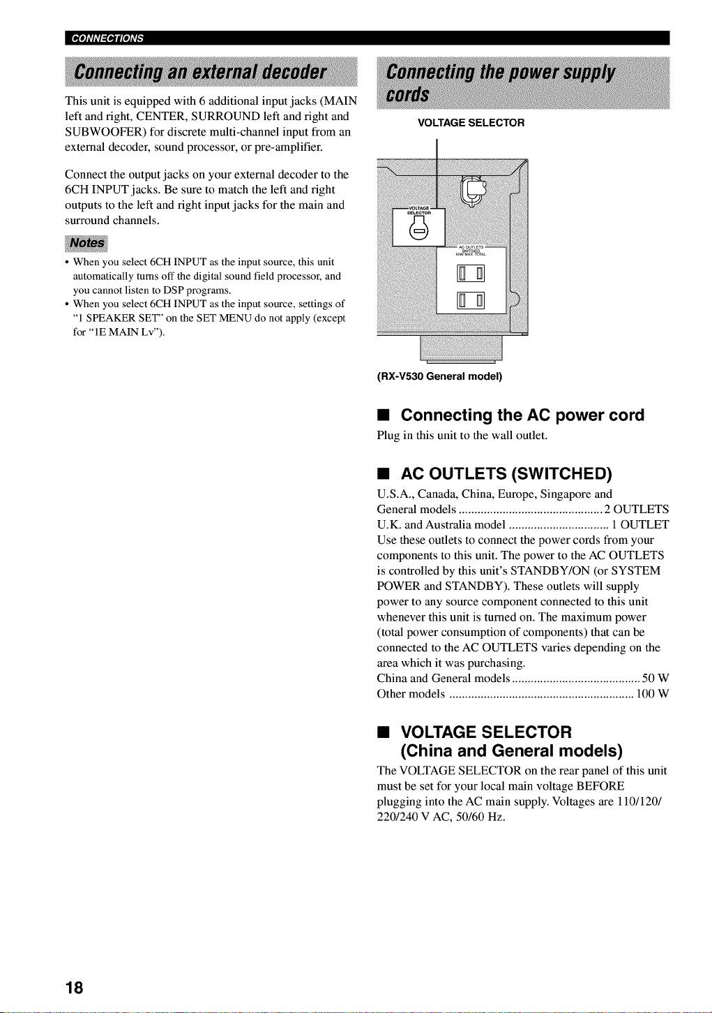
VOLTAGE SELECTOR
• When you select 6CH INPUT as the input source, this unit
automatically turns off the digital sound field processor, and
you cannot listen to DSP programs.
• When you select 6CH INPUT as the input source, settings of
"1 SPEAKER SET" on the SET MENU do not apply (except
for "IE MAIN Lv").
(RX-V530 General model)
•Connecting the AC power cord
Plug in this unit to the wall outlet.
•AC OUTLETS (SWITCHED)
U.S.A., Canada, China, Europe, Singapore and
General models .............................................. 2 OUTLETS
U.K. and Australia model ................................. OUTLET
Use these outlets to connect the power cords from your
components to this unit. The power to the AC OUTLETS
is controlled by this unit's STANDBY/ON (or SYSTEM
POWER and STANDBY). These outlets will supply
power to any source component connected to this unit
whenever this unit is turned on. The maximum power
(total power consumption of components) that can be
connected to the AC OUTLETS varies depending on the
area which it was purchasing.
China and General models ......................................... 50 W
Other models ........................................................... 100 W
•VOLTAGE SELECTOR
(China and General models)
The VOLTAGE SELECTOR on the rear panel of this unit
must be set for your local main voltage BEFORE
plugging into the AC main supply. Voltages are 110/120/
220/240 V AC, 50/60 Hz.
18
_ioli'ffl_iNi'F
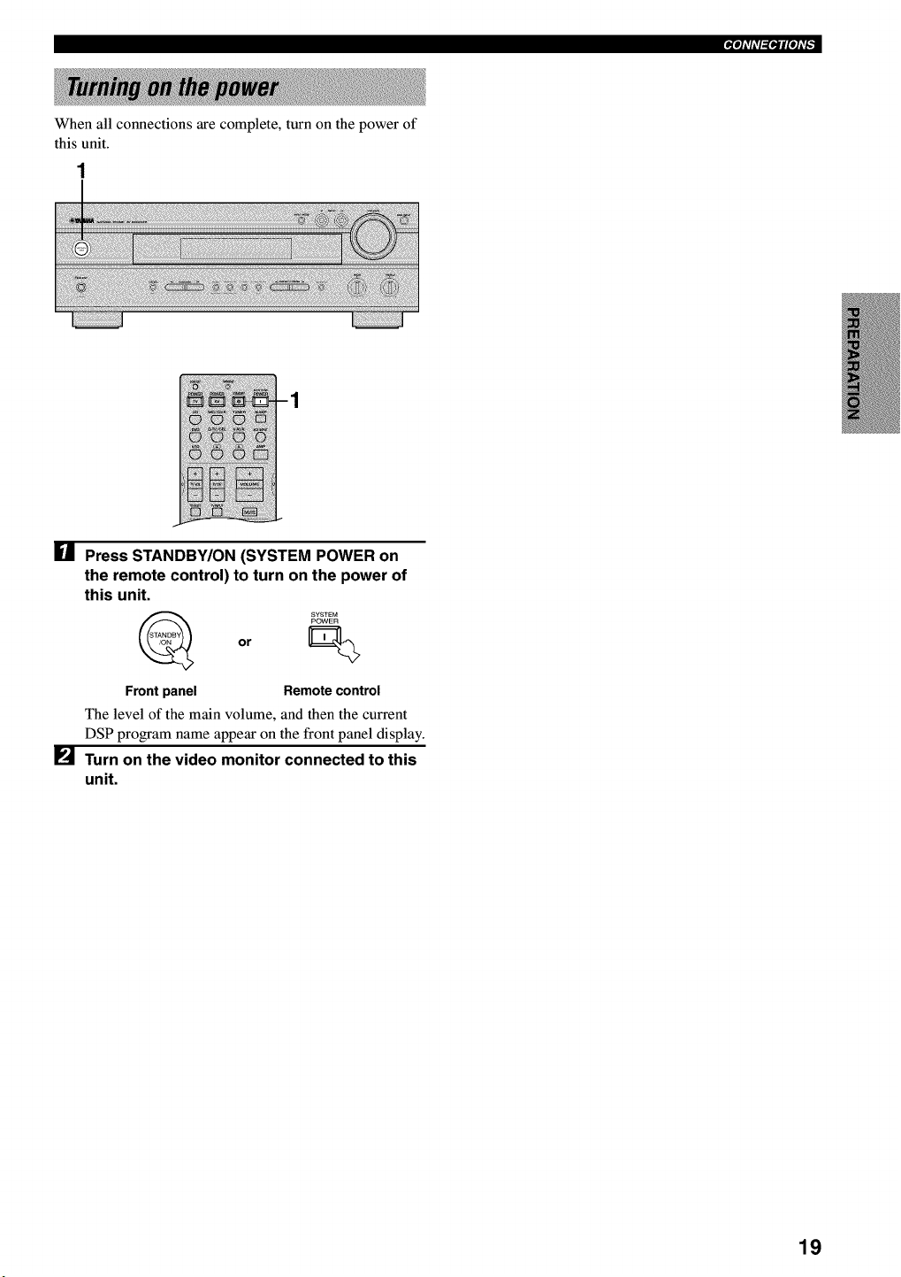
When all connections are complete, turn on the power of
this unit.
[] Press STANDBY/ON (SYSTEM POWER on
the remote control) to turn on the power of
this unit.
or
Front panel Remote control
The level of the main volume, and then the current
DSP program name appear on the front panel display.
[] Turn on the video monitor connected to this
unit.
19
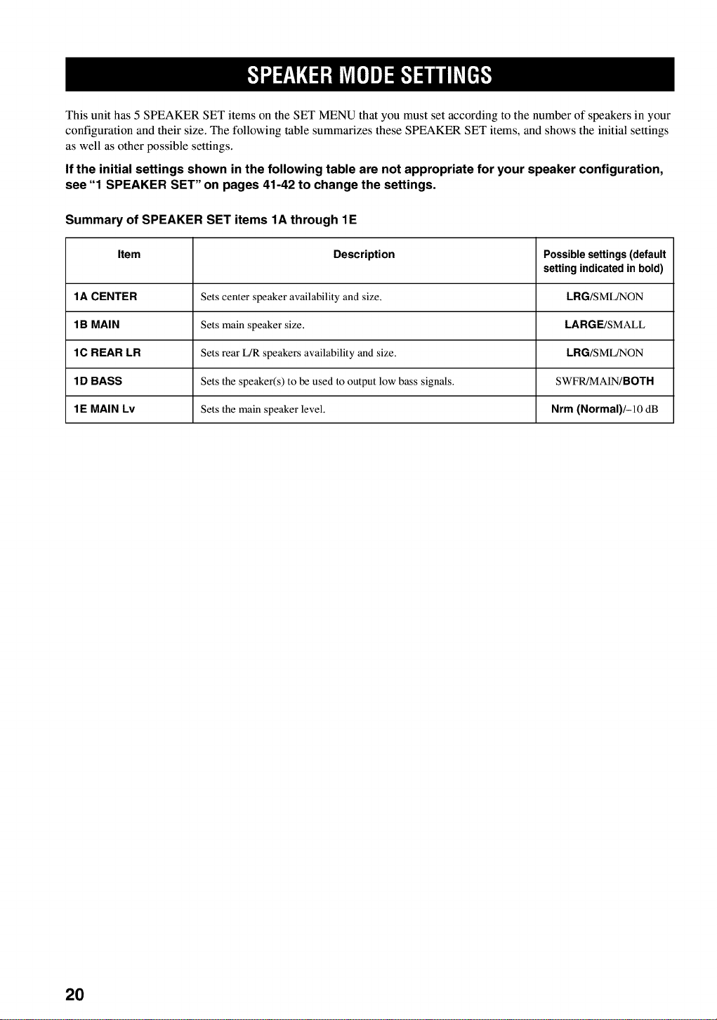
This unit has 5 SPEAKER SET items on the SET MENU that you must set according to the number of speakers in your
configuration and their size. The following table summarizes these SPEAKER SET items, and shows the initial settings
as well as other possible settings.
If the initial settings shown in the following table are not appropriate for your speaker configuration,
see "1 SPEAKER SET" on pages 41-42 to change the settings.
Summary of SPEAKER SET items 1A through 1E
Item Description Possible settings (default
setting indicated in bold)
1A CENTER Sets center speaker availability and size. LRG/SML/NON
1 B MAIN Sets main speaker size. LARGE/SMALL
1C REAR LR Sets rear L/R speakers availability and size. LRG/SML/NON
1 D BASS Sets the speaker(s) to be used to output low bass signals. SWFR/MAIN/BOTH
1E MAIN Lv Sets the main speaker level. Nrm (Normal)/-10 dB
2O
This section explains how to adjust speaker output levels
using the test tone generator. When this adjustment is
complete, the output level heard at the listening position
should be the same from each speaker. This is important
for best performance of the digital sound field processor,
and the various decoders (Dolby Digital, Dolby Pro
Logic, Dolby Pro Logic II and DTS).
• Since this unit cannot enter the test mode while headphones are
connected to this unit, be sure to unplug the headphones from
the PHONES jack when using the test tone.
Use the test tone to balance the output levels of the
speakers. The adjustment of each speaker output level
should be made at your listening position using the
remote control.
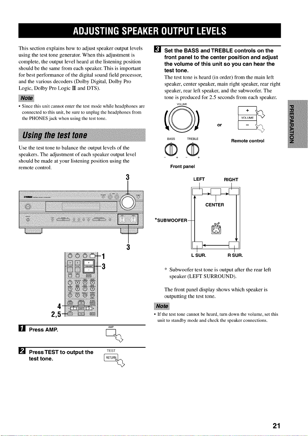
3
1
2,5
U Press AMP.
[] PressTEST to output the
test tone.
AMP
Q
TEST
[] Set the BASS and TREBLE controls on the
front panel to the center position and adjust
the volume of this unit so you can hear the
test tone.
The test tone is heard (in order) from the main left
speaker, center speaker, main right speaker, rear right
speaker, rear left speaker, and the subwoofer. The
tone is produced for 2.5 seconds from each speaker.
VOLUME
BASS TREBLE
QQ Remote control
Front panel
LEFT RIGHT
L SUR. R SUR.
* Subwoofer test tone is output after the rear left
speaker (LEFT SURROUND).
The front panel display shows which speaker is
outputting the test tone.
• If the test tone cannot be heard, turn down the volume, set this
unit to standby mode and check the speaker connections.
21
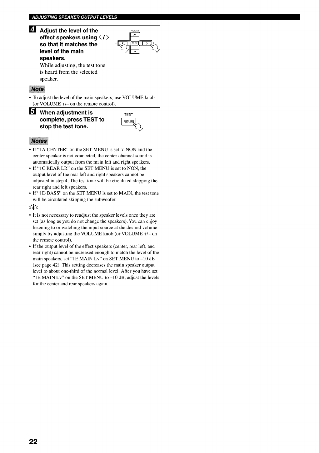
[] Adjust the level of the
effect speakers using < /)
so that it matches the
level of the main
speakers.
While adjusting, the test tone
is heard from the selected
speaker.
•To adjust the level of the main speakers, use VOLUME knob
(or VOLUME +/- on the remote control).
When adjustment is TEST
complete, press TEST to __
stop the test tone.
•If "IA CENTER" on the SET MENU is set to NON and the
center speaker is not connected, the center channel sound is
automatically output from the main left and right speakers.
• If "IC REAR LR" on the SET MENU is set to NON, the
output level of the rear left and right speakers cannot be
adjusted in step 4. The test tone will be circulated skipping the
rear right and left speakers.
• If"lD BASS" on the SET MENU is set to MAIN, the test tone
will be circulated skipping the subwoofer.
_%-
• It is not necessary to readjust the speaker levels once they are
set (as long as you do not change the speakers). You can enjoy
listening to or watching the input source at the desired volume
simply by adjusting the VOLUME knob (or VOLUME +/- on
the remote control).
• If the output level of the effect speakers (center, rear left, and
rear right) cannot be increased enough to match the level of the
main speakers, set "1E MAIN Lv" on SET MENU to -10 dB
(see page 42). This setting decreases the main speaker output
level to about one-third of the normal level. After you have set
"IE MAIN Lv" on the SET MENU to -10 dB, adjust the levels
for the center and rear speakers again.
22
1 3 5 3
:: ): : :; : : ::; .....................................
6 5
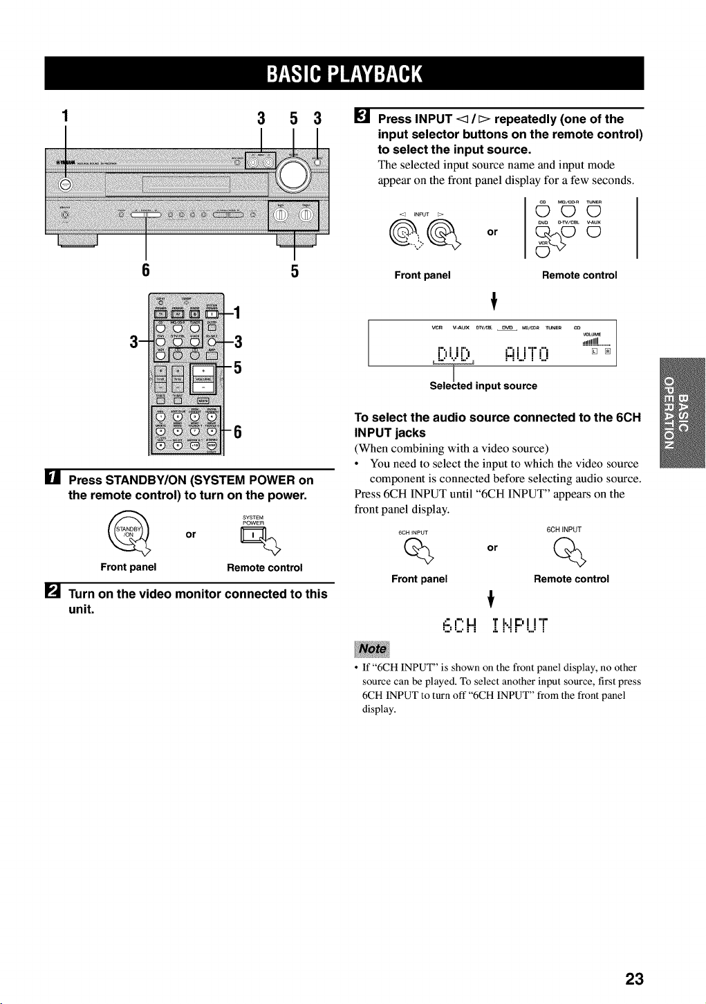
[] Press STANDBY/ON (SYSTEM POWER on
the remote control) to turn on the power.
or
Front panel Remote control
[] Turn on the video monitor connected to this
unit.
[] Press INPUT <1/[> repeatedly (one of the
input selector buttons on the remote control)
to select the input source.
The selected input source name and input mode
appear on the front panel display for a few seconds.
0r
([_ m_/cD_ TuNE_
O0
_v_ _-IV/CSL _AUX
Front panel Remote control
VCR V-AUX D]V/CB_ O_ MD/CDR TUNER CO
VOLt_aE
,,!!!!!!........
i",i ir", i:::iii'i"f"i [] _
,nputlL2"
To select the audio source connected to the 6CH
IN PUT jacks
(When combining with a video source)
• You need to select the input to which the video source
component is connected before selecting audio source.
Press 6CH INPUT until "6CH INPUT" appears on the
front panel display.
6CH INPUT 6CH iNPUT
Qor %
Front panel Remote control
6 CH :[I,.IF:'UT
•If "6CH INPUT" is shown on the front panel display, no other
source can be played. To select another input source, first press
6CH INPUT to turn off "6CH INPUT" from the front panel
display.
23

II :Y_,g:.][e,l ".lW,_| "dr.P_T¢.];
[] Start playback or select a broadcast station
on the source component.
Refer to the operation instructions for the
component.
Adjust the volume to the desired level.
The volume level is displayed digitally.
Example: -70 dB
Control range: VOLUME MUTE (minimum) to
0 dB (maximum)
The volume level indicator also shows the current
volume level as a bar graph.
If desired, use BASS and TREBLE. These controls
only effect the sound from the main speakers.
BASS TREBLE
or
--,j
Remote control
Front panel
•If you increase or decrease the high-frequency or the low-
frequency sound to an extreme level, the tonal quality from the
center and rear speakers may not match that of the main left
and right speakers.
• If you have connected a recording component to the VCR
OUT, or MD/CD-R OUT jacks, and you notice distortion or
low volume during playback of other components, try turning
the recording component on.
[] Select a DSP program if desired.
Use PROGRAM <3 /[> (DSP program buttons on
the remote control) to select a DSP program. See
pages 29 to 33 for details about DSP programs.
When using the remote control, press AMP before
selecting a DSP program.
Front panel Remote control
•BGV (background video) function
The BGV function allows you to enjoy video images
from a video source together with sounds from an audio
source. For example, you can enjoy listening to classical
music while having beautiful scenery from a video source
on the video monitor.
Select a source from the video group, then select a source
from the audio group using the input selector buttons on
the remote control. BGV selections cannot be made with
INPUT <3 !l> on the front panel.
•To mute the sound
•Press MUTE on the
remote control.
To resume the audio output,
press MUTE again.
_%-
• You can also cancel mute by pressing VOLUME +1-, etc.
• During muting, the "MUTE" indicator flashes on the front
panel display.
•When you have finished using
this unit
•Press STANDBY/ON (STANDBY on the
remote control) to set this unit in the
standby mode.
STANDBY
or
Front panel Remote control
24
This unit comes with a variety input jacks. You can select
the type of input signals you desire.
Each time you turn on the power of this unit, the input
mode is set according to "8 INPUT MODE" setting on
the SET MENU (see page 45 for details).
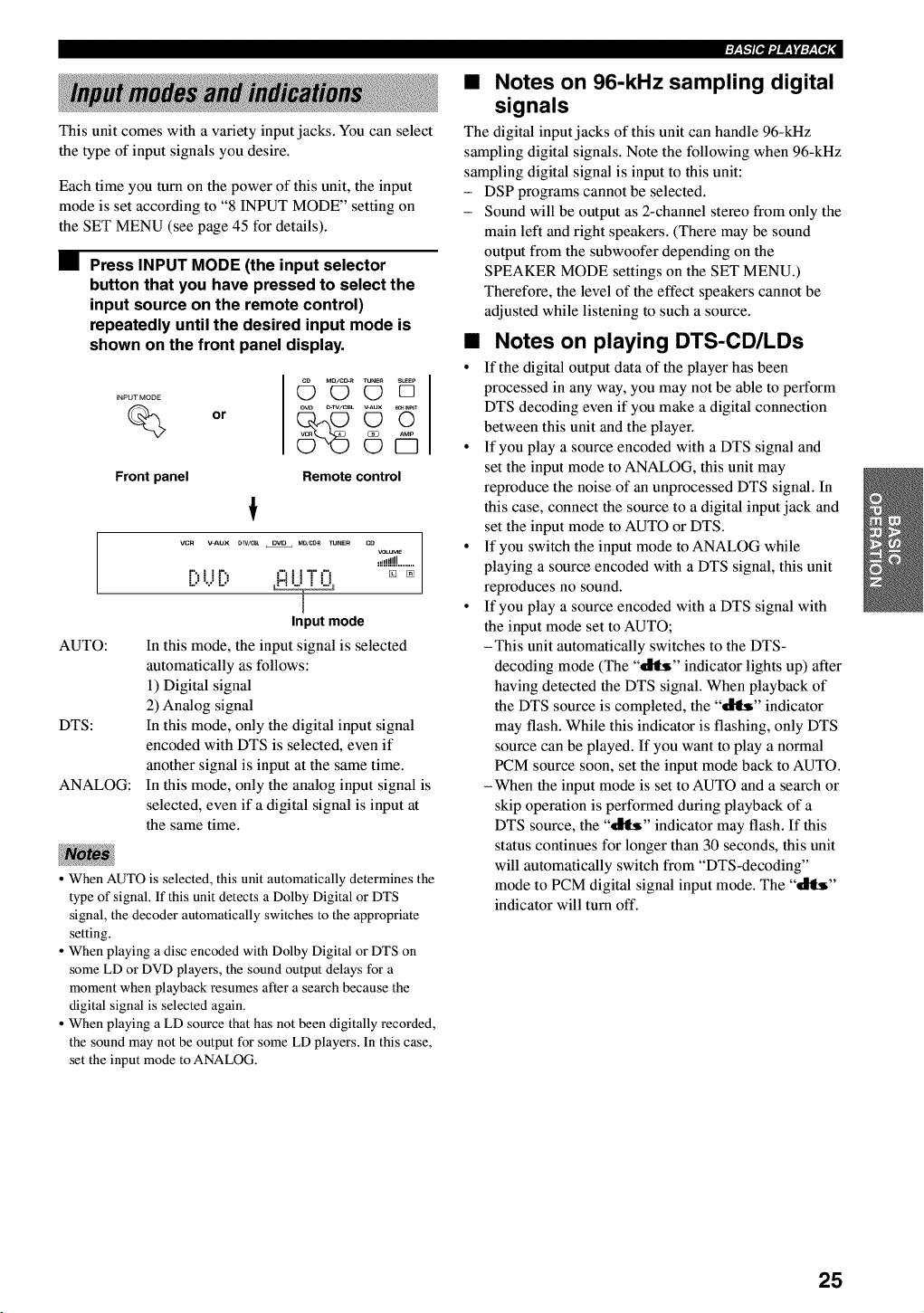
•Press INPUT MODE (the input selector
button that you have pressed to select the
input source on the remote control)
repeatedly until the desired input mode is
shown on the front panel display.
INPUT MODE
%or
Q_ M_/c_ TUNES SLEEPOOD
©€5
AUTO:
DTS:
ANALOG:
Front panel Remote control
!
VCR V=AUX _W/_ DVO MO/_ _NER CO
VOLUMe
.!dd!!!........
t%! !P,, _'_! !"l"t'_ _ [N
IJUIJ HI i i i i
Input mode
In this mode, the input signal is selected
automatically as follows:
1) Digital signal
2) Analog signal
In this mode, only the digital input signal
encoded with DTS is selected, even if
another signal is input at the same time.
In this mode, only the analog input signal is
selected, even if a digital signal is input at
the same time.
• When AUTO is selected, this unit automatically determines the
type of signal. If this unit detects a Dolby Digital or DTS
signal, the decoder automatically switches to the appropriate
setting.
• When playing a disc encoded with Dolby Digital or DTS on
some LD or DVD players, the sound output delays for a
moment when playback resumes after a search because the
digital signal is selected again.
• When playing a LD source that has not been digitally recorded,
the sound may not be output for some LD players. In this case,
set the input mode to ANALOG.
• Notes on 96-kHz sampling digital
signals
The digital input jacks of this unit can handle 96-kHz
sampling digital signals. Note the following when 96-kHz
sampling digital signal is input to this unit:
- DSP programs cannot be selected.
- Sound will be output as 2-channel stereo from only the
main left and right speakers. (There may be sound
output from the subwoofer depending on the
SPEAKER MODE settings on the SET MENU.)
Therefore, the level of the effect speakers cannot be
adjusted while listening to such a source.
•Notes on playing DTS-CD/LDs
• If the digital output data of the player has been
processed in any way, you may not be able to perform
DTS decoding even if you make a digital connection
between this unit and the player.
° If you play a source encoded with a DTS signal and
set the input mode to ANALOG, this unit may
reproduce the noise of an unprocessed DTS signal. In
this case, connect the source to a digital input jack and
set the input mode to AUTO or DTS.
° If you switch the input mode to ANALOG while
playing a source encoded with a DTS signal, this unit
reproduces no sound.
° If you play a source encoded with a DTS signal with
the input mode set to AUTO;
-This unit automatically switches to the DTS-
decoding mode (The "_" indicator lights up) after
having detected the DTS signal. When playback of
the DTS source is completed, the "_" indicator
may flash. While this indicator is flashing, only DTS
source can be played. If you want to play a normal
PCM source soon, set the input mode back to AUTO.
-When the input mode is set to AUTO and a search or
skip operation is performed during playback of a
DTS source, the "_" indicator may flash. If this
status continues for longer than 30 seconds, this unit
will automatically switch from "DTS-decoding"
mode to PCM digital signal input mode. The "_"
indicator will turn off.
25
I:Y_,_:'][e,l ".lf,_| "d:P_T_ ;
You can enhance your listening experience by selecting a
DSP program. For details about each program, see pages
29 to 33.
PROGRAM <:1/_>
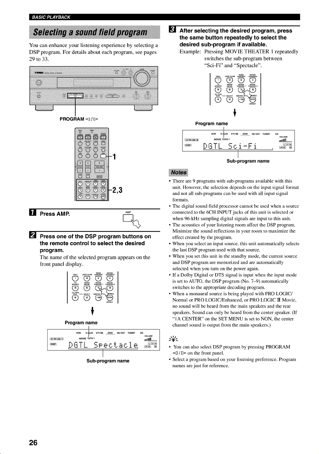
ire] After selecting the desired program, press
the same button repeatedly to select the
desired sub-program if available.
Example: Pressing MOVIE THEATER 1 repeatedly
switches the sub-program between
"Sci-Fi" and "Spectacle".
_eNTE_
_LL a_C,US CO_CE_T T_NMENT
OO_9_
s_s M_IE _eAT_R_ _TeR _
E_cv
Program name
vcR v_ux _V/CeL OVD M0/CO_ TUNER
MOVIE_HTR I
F:,i':iT l ':-.r. i - F- i
I
Sub-program name
co
voLu_
,!!!!!!!!........
[] Press AMP. AMP
[] Press one of the DSP program buttons on
the remote control to select the desired
program.
The name of the selected program appears on the
front panel display.
_eNTE_
_LL a_C,US CO_CE_TT_NMENT
O_O_
Program name
vc_ v-_ux _V/CSL OVD _O/CO_ TUNE_
MOVm THT_
_[:,i3T L - - - - ÷ c.1e,
_, P_......._
Sub-program name
co
_e!!!!!!J........
• There are 9 programs with sub-programs available with this
unit. However, the selection depends on the input signal format
and not all sub-programs can be used with all input signal
formats.
• The digital sound field processor cannot be used when a source
connected to the 6CH INPUT jacks of this unit is selected or
when 96-kHz sampling digital signals are input to this unit.
• The acoustics of your listening room affect the DSP program.
Minimize the sound reflections in your room to maximize the
effect created by the program.
• When you select an input source, this unit automatically selects
the last DSP program used with that source.
• When you set this unit in the standby mode, the current source
and DSP program are memorized and are automatically
selected when you turn on the power again.
• If a Dolby Digital or DTS signal is input when the input mode
is set to AUTO, the DSP program (No. 7-9) automatically
switches to the appropriate decoding program.
• When a monaural source is being played with PRO LOGIC/
Normal or PRO LOGIC/Enhanced, or PRO LOGIC lI Movie,
no sound will be heard from the main speakers and the rear
speakers. Sound can only be heard from the center speaker. (If
"IA CENTER" on the SET MENU is set to NON, the center
channel sound is output from the main speakers.)
• You can also select DSP program by pressing PROGRAM
<_ /_> on the front panel.
• Select a program based on your listening preference. Program
names are just for reference.
26
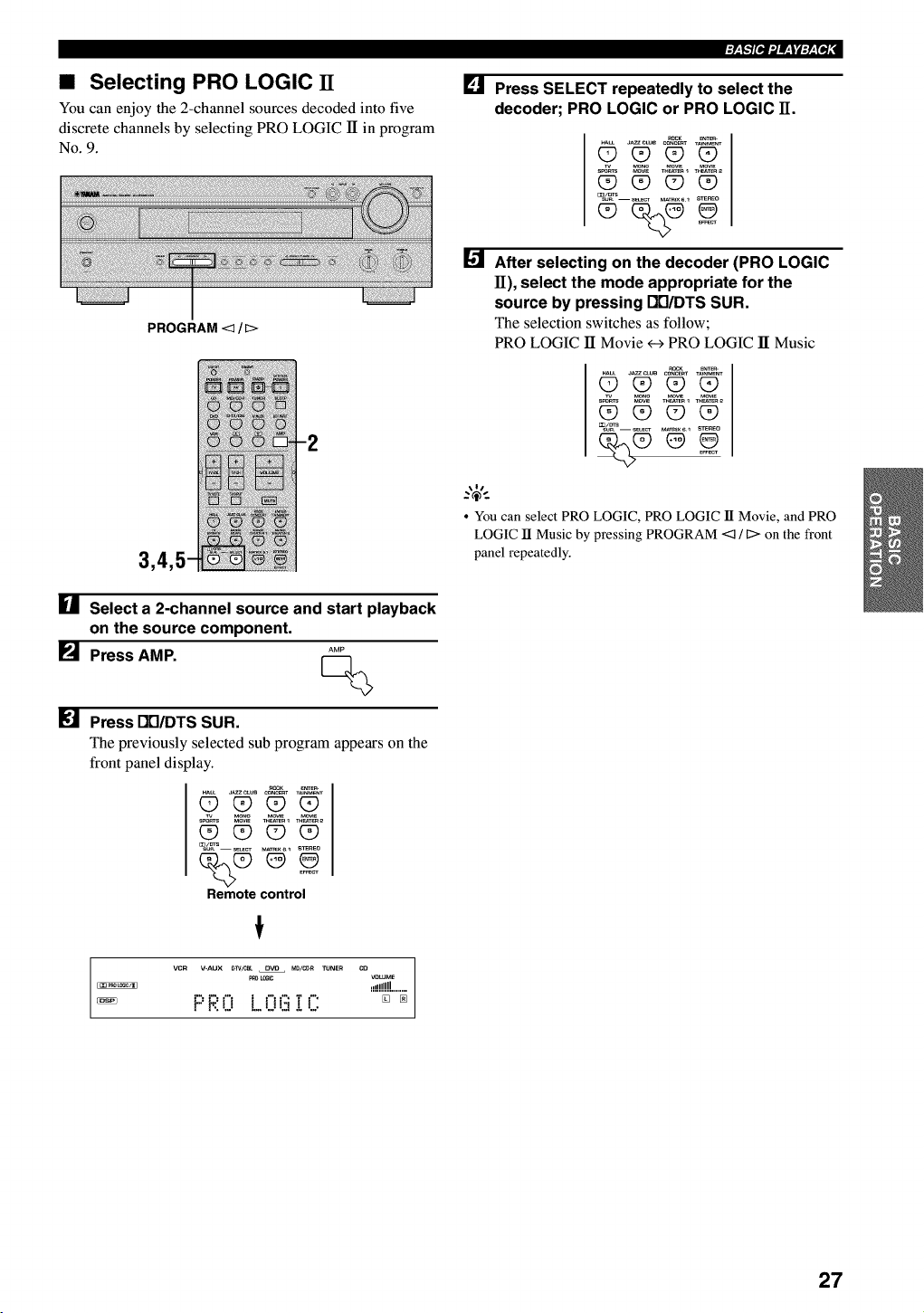
•Selecting PRO LOGIC IT
You can enjoy the 2-channel sources decoded into five
discrete channels by selecting PRO LOGIC 1Tin program
No. 9.
PROGRAM <q / D>
[] Select a 2-channel source and start playback
on the source component.
[] Press AMP. AMP
[] Press Dtl/DTS SUR.
The previously selected sub program appears on the
front panel display.
_LL J_CL_ CONCERTT_NME_T
O_(90
(D (D (D (9
E_CT
Remote control
VCR V=AUX _>]V/CBL DVD MD/C_R TUNER CO VOLUME
_o _ .d!!!!H........
PRO L.OG!C: [] _
[] Press SELECT repeatedly to select the
decoder; PRO LOGIC or PRO LOGIC H.
ROCK _
OOOO
_/_S--sE_CT MAT_IX_I STEREO
After selecting on the decoder (PRO LOGIC
11), select the mode appropriate for the
source by pressing DB/DTS SUR.
The selection switches as follow;
PRO LOGIC ]I Movie <-->PRO LOGIC 1TMusic
_L_ J_ CONC_T T_NMENT
_ Q_ Q9 Q9
CD Q9 Q9 _
•You can select PRO LOGIC, PRO LOGIC lI Movie, and PRO
LOGIC lI Music by pressing PROGRAM <:_ !C> on the front
panel repeatedly.
27
I:Y_,g:'][e,l ".lW,_t "d:P_T_ ;
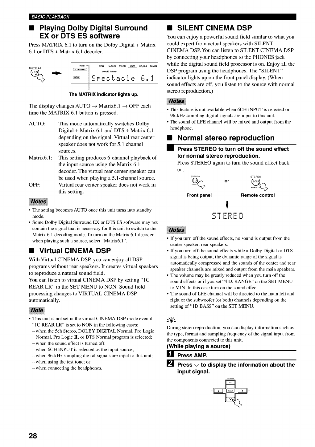
•Playing Dolby Digital Surround
EX or DTS ES software
Press MATRIX 6. l to turn on the Dolby Digital +Matrix
6.1 or DTS + Matrix 6.1 decoder.
MATRIX 6 _
%_l vcn V-AUX #w/_ OVD MO/_R TUNEn
MOVIE THT_ 1
"" =""I
"2,F' e' C T..E!C!e' P-,.- _
The MATRIX indicator lights up.
The display changes AUTO _ Matrix6.1 _ OFF each
time the MATRIX 6.1 button is pressed.
AUTO:
Matrix6.1 :
OFF:
This mode automatically switches Dolby
Digital + Matrix 6.1 and DTS + Matrix 6.1
depending on the signal. Virtual rear center
speaker does not work for 5.1 channel
sources.
This setting produces 6-channel playback of
the input source using the Matrix 6.1
decoder. The virtual rear center speaker can
be used when playing a 5.1-channel source.
Virtual rear center speaker does not work in
this setting.
•The setting becomes AUTO once this unit turns into standby
mode.
• Some Dolby Digital Surround EX or DTS ES software may not
contain the signal that is necessary for this unit to switch to the
Matrix 6.1 decoding mode. To turn on the Matrix 6.1 decoder
when playing such a source, select "Matrix& 1".
•Virtual CINEMA DSP
With Virtual CINEMA DSP, you can enjoy all DSP
programs without rear speakers. It creates virtual speakers
to reproduce a natural sound field.
You can listen to virtual CINEMA DSP by setting "IC
REAR LR" in the SET MENU to NON. Sound field
processing changes to VIRTUAL CINEMA DSP
automatically.
• This unit is not set in the virtual CINEMA DSP mode even if
"1C REAR LR" is set to NON in the following cases:
- when the 5ch Stereo, DOLBY DIGITAL Normal, Pro Logic
Normal, Pro Logic lI, or DTS Normal program is selected;
- when the sound effect is turned off;
- when 6CH INPUT is selected as the input source;
- when 96-kHz sampling digital signals are input to this unit;
- when using the test tone; or
- when connecting the headphones.
•SILENT CINEMA DSP
You can enjoy a powerful sound field similar to what you
could expert from actual speakers with SILENT
CINEMA DSR You can listen to SILENT CINEMA DSP
by connecting your headphones to the PHONES jack
while the digital sound field processor is on. Enjoy all the
DSP program using the headphones. The "SILENT"
indicator lights up on the front panel display. (When
sound effects are off, you listen to the source with normal
stereo reproduction.)
•This feature is not available when 6CH INPUT is selected or
96-kHz sampling digital signals are input to this unit.
• The sound of LFE channel will be mixed and output from the
headphone.
Normal stereo reproduction
Press STEREO to turn off the sound effect
for normal stereo reproduction.
Press STEREO again to turn the sound effect back
on.
STEREO STEREO
Front panel Remote control
," =1" I"= I '=, I--' ,",
":, JL::i'-:i:.i..i
• If you turn oft" the sound effects, no sound is output from the
center speaker, rear speakers.
• If you turn off the sound effects while a Dolby Digital or DTS
signal is being output, the dynamic range of the signal is
automatically compressed and the sounds of the center and rear
speaker channels are mixed and output from the main speakers.
• The volume may be greatly reduced when you turn off the
sound effects or if you set "4 D. RANGE" on the SET MENU
to MIN. In this case turn on the sound effect.
• The sound of LFE channel will be directed to the main left and
right or the subwoofer (or both) channels depending on the
setting of "ID BASS" on the SET MENU.
During stereo reproduction, you can display information such as
the type, format and sampling frequency of the signal input from
the components connected to this unit.
(While playing a source)
HPress AMP.
[] Press vto display the information about the
input signal.
PREaT_H
28
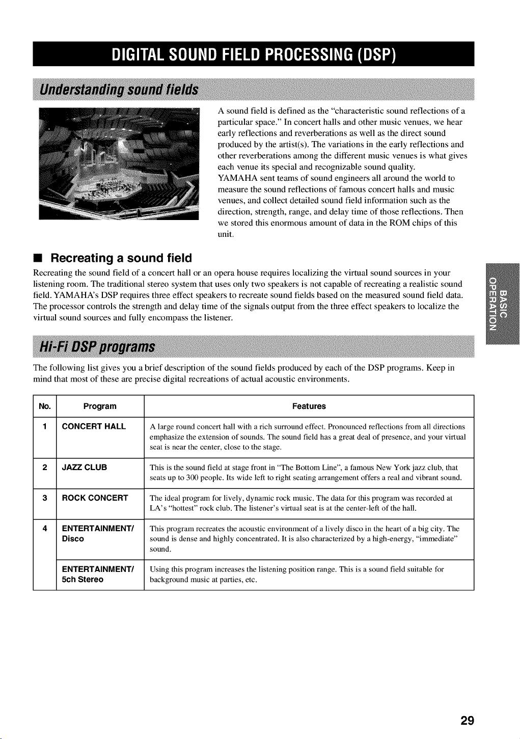
A sound field is defined as the "characteristic sound reflections of a
particular space." In concert halls and other music venues, we hear
early reflections and reverberations as well as the direct sound
produced by the artist(s). The variations in the early reflections and
other reverberations among the different music venues is what gives
each venue its special and recognizable sound quality.
YAMAHA sent teams of sound engineers all around the world to
measure the sound reflections of famous concert halls and music
venues, and collect detailed sound field information such as the
direction, strength, range, and delay time of those reflections. Then
we stored this enormous amount of data in the ROM chips of this
unit.
•Recreating a sound field
Recreating the sound field of a concert hall or an opera house requires localizing the virtual sound sources in your
listening room. The traditional stereo system that uses only two speakers is not capable of recreating a realistic sound
field. YAMAHA's DSP requires three effect speakers to recreate sound fields based on the measured sound field data.
The processor controls the strength and delay time of the signals output from the three effect speakers to localize the
virtual sound sources and fully encompass the listener.
The following list gives you a brief description of the sound fields produced by each of the DSP programs. Keep in
mind that most of these are precise digital recreations of actual acoustic environments.
No. Program Features
1 CONCERT HALL A large round concert hall with a rich surround effect. Pronounced reflections from all directions
emphasize the extension of sounds. The sound field has a great deal of presence, and your virtual
seat is near the center, close to the stage.
2 JAZZ CLUB This is the sound field at stage front in "The Bottom Line", a famous New York jazz club, that
seats up to 3(X) people. Its wide left to right seating arrangement offers a real and vibrant sound.
3 ROCK CONCERT The ideal program for lively, dynamic rock music. The data for this program was recorded at
LA's "hottest" rock club. The listener's virtual seat is at the center-left of the hall.
4 ENTERTAINMENT/ This program recreates the acoustic environment of a lively disco in the heart of a big city. The
Disco sound is dense and highly concentrated. It is also characterized by a high-energy, "immediate"
sound.
ENTERTAINMENT/ Using this program increases the listening position range. This is a sound field suitable for
5Ch Stereo background music at parties, etc.
29
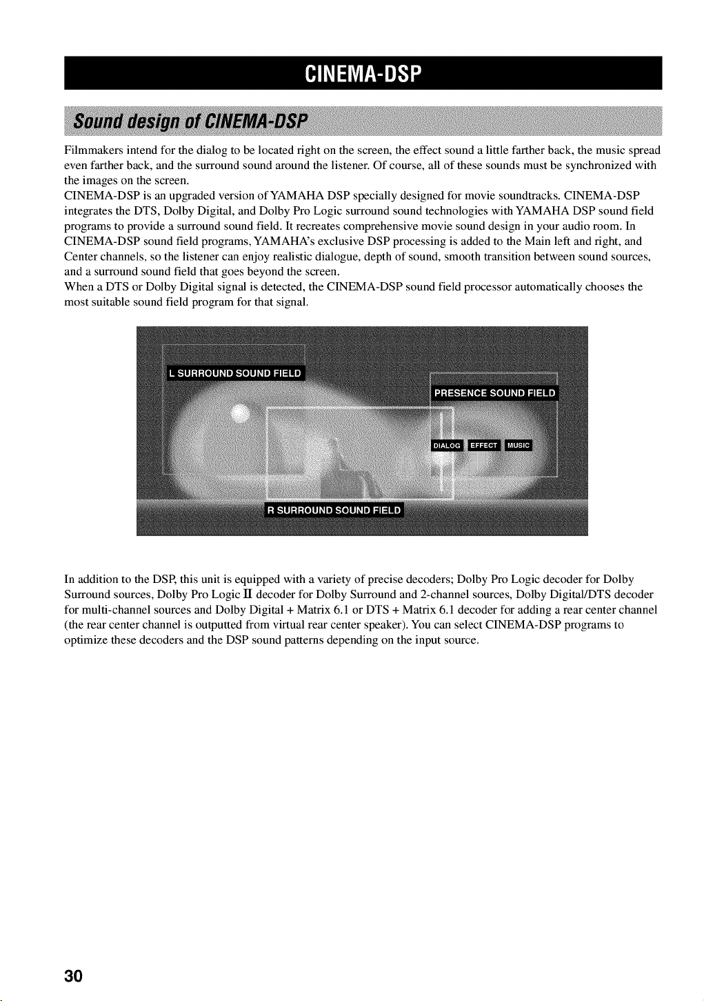
Filmmakers intend for the dialog to be located fight on the screen, the effect sound a little farther back, the music spread
even farther back, and the surround sound around the listener. Of course, all of these sounds must be synchronized with
the images on the screen.
CINEMA-DSP is an upgraded version of YAMAHA DSP specially designed for movie soundtracks. CINEMA-DSP
integrates the DTS, Dolby Digital, and Dolby Pro Logic surround sound technologies with YAMAHA DSP sound field
programs to provide a surround sound field. It recreates comprehensive movie sound design in your audio room. In
CINEMA-DSP sound field programs, YAMAHA's exclusive DSP processing is added to the Main left and right, and
Center channels, so the listener can enjoy realistic dialogue, depth of sound, smooth transition between sound sources,
and a surround sound field that goes beyond the screen.
When a DTS or Dolby Digital signal is detected, the CINEMA-DSP sound field processor automatically chooses the
most suitable sound field program for that signal.
In addition to the DSP, this unit is equipped with a variety of precise decoders; Dolby Pro Logic decoder for Dolby
Surround sources, Dolby Pro Logic lI decoder for Dolby Surround and 2-channel sources, Dolby Digital/DTS decoder
for multi-channel sources and Dolby Digital + Matrix 6.1 or DTS + Matrix 6.1 decoder for adding a rear center channel
(the rear center channel is outputted from virtual rear center speaker). You can select CINEMA-DSP programs to
optimize these decoders and the DSP sound patterns depending on the input source.
3O
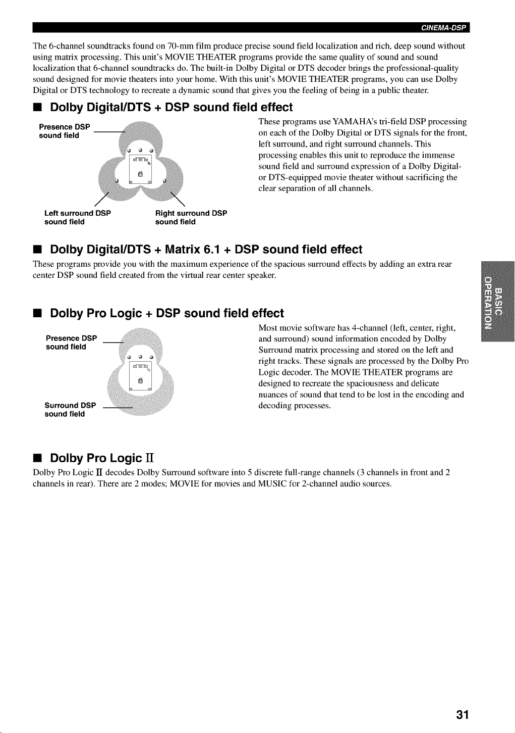
The 6-channel soundtracks found on 70-mm film produce precise sound field localization and rich, deep sound without
using matrix processing. This unit's MOVIE THEATER programs provide the same quality of sound and sound
localization that 6-channel soundtracks do. The built-in Dolby Digital or DTS decoder brings the professional-quality
sound designed for movie theaters into your home. With this unit's MOVIE THEATER programs, you can use Dolby
Digital or DTS technology to recreate a dynamic sound that gives you the feeling of being in a public theater.
•Dolby Digital/DTS + DSP sound field effect
Presence DSP These programs use YAMAHA's tri-field DSP processing
sound field on each of the Dolby Digital or DTS signals for the front,
left surround, and fight surround channels. This
processing enables this unit to reproduce the immense
sound field and surround expression of a Dolby Digital-
or DTS-equipped movie theater without sacrificing the
clear separation of all channels.
Left surround DSP Right surround DSP
sound field sound field
•Dolby Digital/DTS +Matrix 6.1 + DSP sound field effect
These programs provide you with the maximum experience of the spacious surround effects by adding an extra rear
center DSP sound field created from the virtual rear center speaker.
•Dolby Pro Logic + DSP sound field effect
Presence DSP
sound field
Surround DSP
sound field
i!ii !I Most movie software has 4-channel (left, center, right,
and surround) sound information encoded by Dolby
Surround matrix processing and stored on the left and
right tracks. These signals are processed by the Dolby Pro
Logic decoder. The MOVIE THEATER programs are
designed to recreate the spaciousness and delicate
nuances of sound that tend to be lost in the encoding and
decoding processes.
•Dolby Pro Logic IT
Dolby Pro Logic II decodes Dolby Surround software into 5 discrete full-range channels (3 channels in front and 2
channels in rear). There are 2 modes; MOVIE for movies and MUSIC for 2-channel audio sources.
31
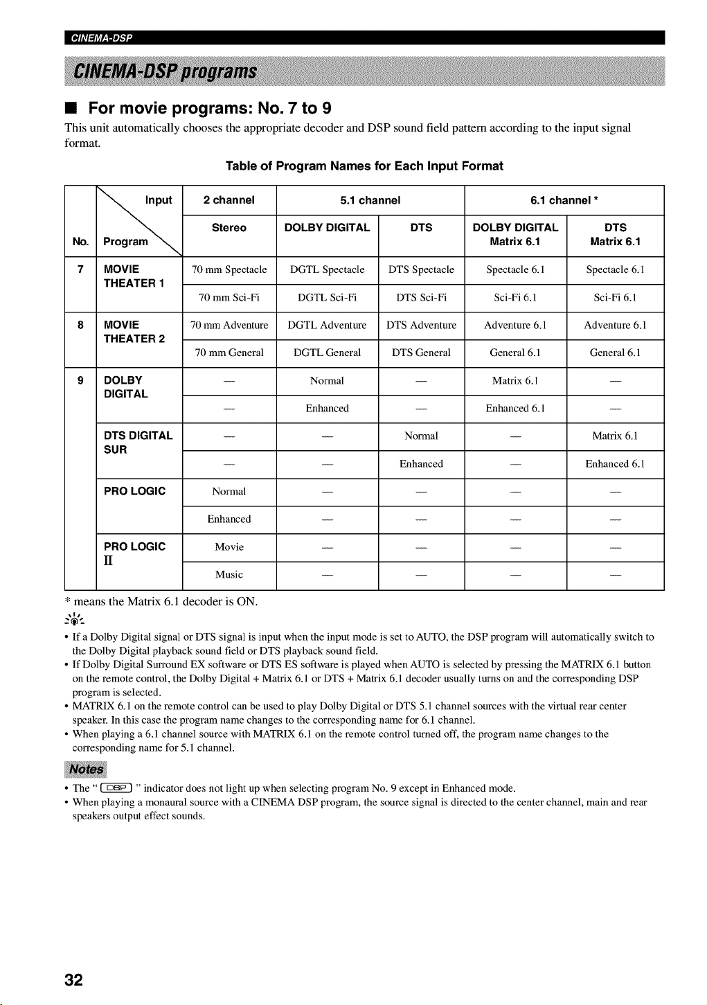
•For movie programs: No. 7 to 9
This unit automatically chooses the appropriate decoder and DSP sound field pattern according to the input signal
format.
Table of Program Names for Each Input Format
put 2 channel 5.1 channel 6.1 channel *
Stereo DOLBY DIGITAL DTS DOLBY DIGITAL DTS
No. Program _Matrix 6.1 Matrix 6.1
7 MOVIE 70 mm Spectacle DGTL Spectacle DTS Spectacle Spectacle 6.1 Spectacle 6.1
THEATER 1
70 mm Sci-Fi DGTL Sci-Fi DTS Sci-Fi Sci-Fi 6.1 Sci-Fi 6.1
8 MOVIE 70 mm Adventure DGTL Adventure DTS Adventure Adventure 6.1 Adventure 6.1
THEATER 2
70 mm General DGTL General DTS General General 6.1 General 6.1
9 DOLBY -- Normal -- Matrix 6.1 --
DIGITAL
-- Enhanced -- Enhanced 6.1 --
DTS DIGITAL -- -- Normal -- Matrix 6.1
SUR
-- -- Enhanced -- Enhanced 6.1
PRO LOGIC Normal ....
Enhanced ....
PRO LOGIC Movie ....
II
Music ....
* means the Matrix 6.1 decoder is ON.
o If a Dolby Digital signal or DTS signal is input when the input mode is set to AUTO, the DSP program will automatically switch to
the Dolby Digital playback sound field or DTS playback sound field.
o If Dolby Digital Surround EX software or DTS ES software is played when AUTO is selected by pressing the MATRIX 6.1 button
on the remote control, the Dolby Digital + Matrix 6.1 or DTS + Matrix 6.1 decoder usually turns on and the corresponding DSP
program is selected.
o MATRIX 6.1 on the remote control can be used to play Dolby Digital or DTS 5.1 channel sources with the virtual rear center
speaker. In this case the program name changes to the corresponding name for 6. l channel.
o When playing a 6.1 channel source with MATRIX 6.1 on the remote control turned oft', the program name changes to the
corresponding name for 5.1 channel.
• The" _ "indicator does not light up when selecting program No. 9 except in Enhanced mode.
• When playing a monaural source with a CINEMA DSP program, the source signal is directed to the center channel, main and rear
speakers output effect sounds.
32
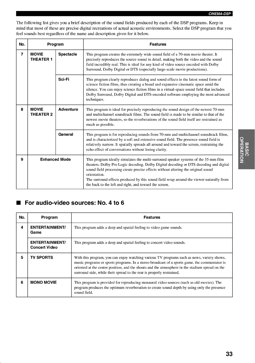
The following list gives you a brief description of the sound fields produced by each of the DSP programs. Keep in
mind that most of these are precise digital recreations of actual acoustic environments. Select the DSP program that you
feel sounds best regardless of the name and description given for it below.
No. Program
7 MOVIE
THEATER 1
MOVIE
THEATER 2
Spectacle
Sci-Fi
Adventure
General
Enhanced Mode
Features
This program creates the extremely wide sound field of a 70-mm movie theater. It
precisely reproduces the source sound in detail, making both the video and the sound
field incredibly real. This is ideal for any kind of video source encoded with Dolby
Surround, Dolby Digital or DTS (especially large-scale movie productions).
This program clearly reproduces dialog and sound effects in the latest sound form of
science fiction films, thus creating a broad and expansive cinematic space amid the
silence. You can enjoy science fiction films in a virtual-space sound field that includes
Dolby Surround, Dolby Digital and DTS-encoded software employing the most advanced
techniques.
This program is ideal for precisely reproducing the sound design of the newest 70-mm
and multichannel soundtrack films. The sound field is made to be similar to that of the
newest movie theaters, so the reverberations of the sound field itself are restrained as
much as possible.
This program is for reproducing sounds from 70-mm and multichannel soundtrack films,
and is characterized by a soft and extensive sound field. The presence sound field is
relatively narrow. It spatially spreads all around and toward the screen, restraining the
echo effect of conversations without losing clarity.
This program ideally simulates the multi-surround speaker systems of the 35-mm film
theaters. Dolby Pro Logic decoding, Dolby Digital decoding or DTS decoding and digital
sound field processing create precise effects without altering the original sound
orientation.
The surround effects produced by this sound field wrap around the viewer naturally from
the back to the left and right, and toward the screen.
•For audio-video sources: No. 4 to 6
No. Program Features
4 ENTERTAINMENT/ This program adds a deep and spatial feeling to video game sounds.
Game
ENTERTAINMENT/ This program adds a deep and spatial feeling to concert video sounds.
Concert Video
5 TV SPORTS With this program, you can enjoy watching various TV programs such as news, variety shows,
music programs or sports programs. In a stereo broadcast of a sports game, the commentator is
oriented at the center position, and the shouts and the atmosphere in the stadium spread on the
surround side, while their spread to the rear is properly restrained.
6 MONO MOVIE This program is provided for reproducing monaural video sources (such as old movies). The
program produces the optimum reverberation to create sound depth by using only the presence
sound field.
33
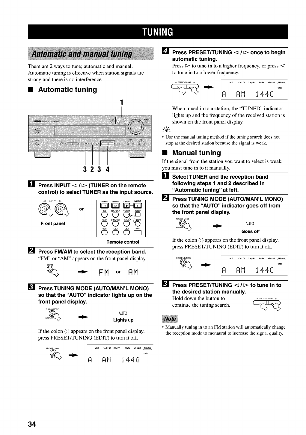
There are 2 ways to tune; automatic and manual.
Automatic tuning is effective when station signals are
strong and there is no interference.
•Automatic tuning
3234
[] Press INPUT <_/D (TUNER on the remote
control) to select TUNER as the input source.
<3 INPUT
Front panel
or
pOWEn POW_ _0By pOWEn
OMO/CD_ TUNER SLEEP
_v_ O-TV/CBL
OO
©©©D
Remotecontrol
[] Press FM/AM to select the reception band.
"FM" or "AM" appears on the front panel display.
F_AM
I'-- I, ,Ij.- j,j or ....i:_!_!
[] Press TUNING MODE (AUTO/MAN'L MONO)
so that the "AUTO" indicator lights up on the
front panel display.
TUNINGMODE
o% AUTO
_T Lights up
If the colon (:) appears on the front panel display,
press PRESET/TUNING (EDIT) to turn it off.
PNESET_UNING VCR V_UX _/_ DVD MD/C_ TUNER
"_ !:i !:it'! !440
[] Press PRESET/TUNING <1 /D once to begin
automatic tuning.
Press Dto tune in to a higher frequency, or press <1
to tune in to a lower frequency.
P_ESETKUNIHG _ VCR V=ALIX [_TV/_ DVD MO/Cg_I TUNER
i::i i::it',1 I 4.4.i"i
When tuned in to a station, the "TUNED" indicator
lights up and the frequency of the received station is
shown on the front panel display.
• Use the manual tuning method if the tuning search does not
stop at the desired station because the signal is weak.
•Manual tuning
If the signal from the station you want to select is weak,
you must tune in to it manually.
[] SelectTUNER and the reception band
following steps I and 2 described in
"Automatic tuning" at left.
[] Press TUNING MODE (AUTO/MAN'L MONO)
so that the "AUTO" indicator goes off from
the front panel display.
TUNEN_MODE
NjTO_ _ AUTO
Goes off
If the colon (:) appears on the front panel display,
press PRESET!TUNING (EDIT) to turn it off.
PRE_ NIt_G VCR V=ALIX [_TV/_ DVD MI3/I_I TUNER
i::i i::it',1 I 4.4.i"i
[] Press PRESET/TUNING <1 /D to tune in to
the desired station manually.
Hold down the button to ...............
continue the tuning search. _'_"-_
• Manually tuning in to an FM station will automatically change
the reception mode to monaural to increase the signal quality.
34
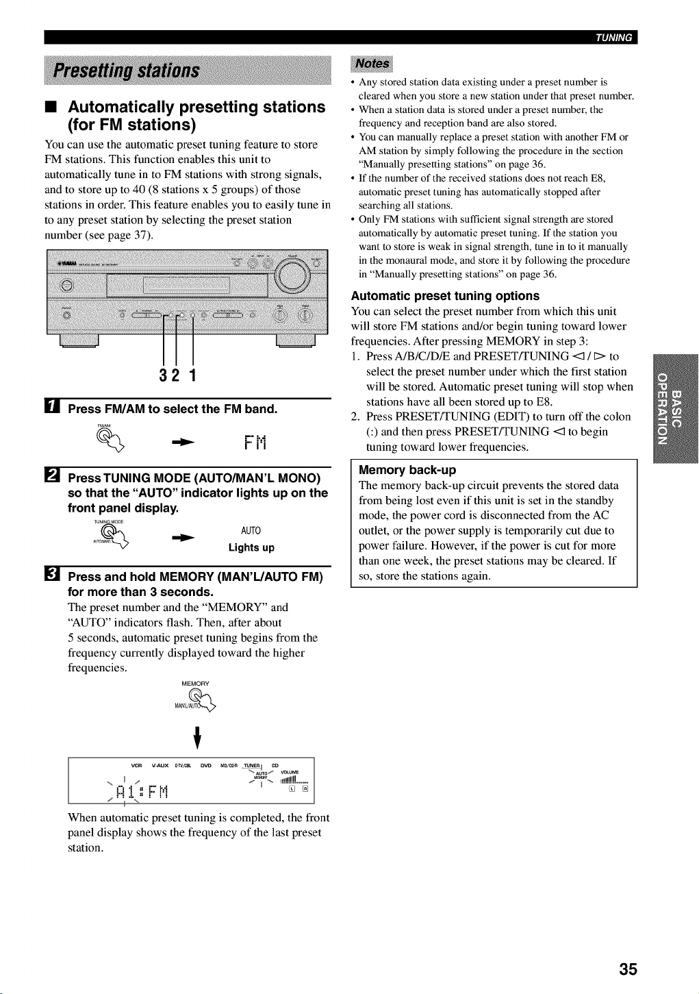
iqi'lli'l•
•Automatically presetting stations
(for FM stations)
You can use the automatic preset tuning feature to store
FM stations. This function enables this unit to
automatically tune in to FM stations with strong signals,
and to store up to 40 (8 stations x 5 groups) of those
stations in order. This feature enables you to easily tune in
to any preset station by selecting the preset station
number (see page 37).
Ill
[]
321
Press FM/AM to select the FM band.
F_AM
,"" i'."i" i'i
PressTUNING MODE (AUTO/MAN'L MONO)
so that the "AUTO" indicator lights up on the
front panel display.
TUNENGMO_E
_uTo_ _ AUTO
Lights up
Press and hold MEMORY (MAN'L/AUTO FM)
for more than 3 seconds.
The preset number and the "MEMORY" and
"AUTO" indicators flash. Then, after about
5 seconds, automatic preset tuning begins from the
frequency currently displayed toward the higher
frequencies.
MEMORY
MAN'UAUT_
t
vcR v-Aux #WILL 13VD Ml_/c_ _ co
"_.Auro1_ v_ur_
,-,m.! ,",€:",,hi ......_'""_
When automatic preset tuning is completed, the front
panel display shows the frequency of the last preset
station.
• Any stored station data existing under a preset number is
cleared when you store a new station under that preset number.
• When a station data is stored under a preset number, the
frequency and reception band are also stored.
• You can manually replace a preset station with another FM or
AM station by simply following the procedure in the section
"Manually presetting stations" on page 36.
• If the number of the received stations does not reach E8,
automatic preset tuning has automatically stopped after
searching all stations.
• Only FM stations with sufficient signal strength are stored
automatically by automatic preset tuning. If the station you
want to store is weak in signal strength, tune in to it manually
in the monaural mode, and store it by following the procedure
in "Manually presetting stations" on page 36.
Automatic preset tuning options
You can select the preset number from which this unit
will store FM stations and/or begin tuning toward lower
frequencies. After pressing MEMORY in step 3:
1. Press A/B/C/DR and PRESET/TUNING <:1/l> to
select the preset number under which the first station
will be stored. Automatic preset tuning will stop when
stations have all been stored up to E8.
2. Press PRESET!TUNING (EDIT) to turn off the colon
C) and then press PRESET/TUNING <3 to begin
tuning toward lower frequencies.
Memory back-up
The memory back-up circuit prevents the stored data
from being lost even if this unit is set in the standby
mode, the power cord is disconnected from the AC
outlet, or the power supply is temporarily cut due to
power failure. However, if the power is cut for more
than one week, the preset stations may be cleared. If
so, store the stations again.
35
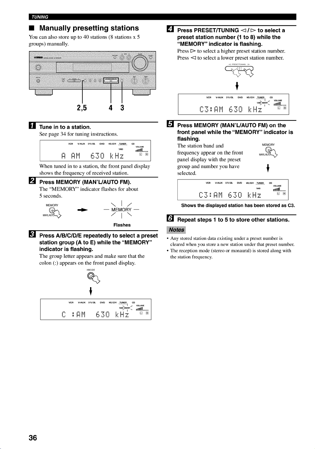
11|_ll7ffF
•Manually presetting stations
You can also store up to 40 stations (8 stations x 5
groups) manually.
2,5 4 3
[] Tune in to a station.
See page 34 for tuning instructions.
vcn V-AUX _w/c_ pro M0/CC_ TUNEr CO
VOtiVE
_ .!i!!!!!!........
_"t _"thi _.' '.2't'_ t.. Lt 7." [] []
r"i r"i I I U ",J U ." ......
When tuned in to a station, the front panel display
shows the frequency of received station.
[] Press MEMORY (MAN'L/AUTO FM).
The "MEMORY" indicator flashes for about
5 seconds.
MEMORY \ I/
_ -- MEMORY-
Flashes
[] Press A/B/C/D/E repeatedly to select a preset
station group (A to E) while the "MEMORY"
indicator is flashing.
The group letter appears and make sure that the
colon (:) appears on the front panel display.
_B,CJDJE
%
!
vcr V-AUX _w/c_ DVD M0/C_ TUNer CO
%I _ VOLUME
r" ,_ _'7t',f (, ":!'t'_ t.. _.t-,. '"'"_"'"_
,." r"i Ii",J U r', i i .':,
[]
[]
Press PRESET/TUNING <3 /[> to select a
preset station number (1 to 8) while the
"MEMORY" indicator is flashing.
Press I> to select a higher preset station number.
Press <3 to select a lower preset station number.
!
VCR V-AUX _W/C_ DVD M0/C0_ TUNER CO
%U _ VOLUME
_L_ ,,1!!!!!........
17.v.,, _"II',I i::,?;17 t.:'H 7 [] []
-,,'l I1 .................
Press MEMORY (MAN'L/AUTO FM) on the
front panel while the "MEMORY" indicator is
flashing.
The station band and MEMORY
frequency appear on the front MA_U_
panel display with the preset
group and number you have
selected. T
vcR V-AUX _W/mt OVD m0/co_ TUNEr CO
vc_uM_
_m ,,,illllll
177; " _"II',I i::,"_"17 t.:'H 7 [] []
.... I1 ...... ,,'l .........
Shows the displayed station has been stored as C3.
[] Repeat steps I to 5 to store other stations.
•Any stored station data existing under a preset number is
cleared when you store a new station under that preset number.
•The reception mode (stereo or monaural) is stored along with
the station frequency.
36
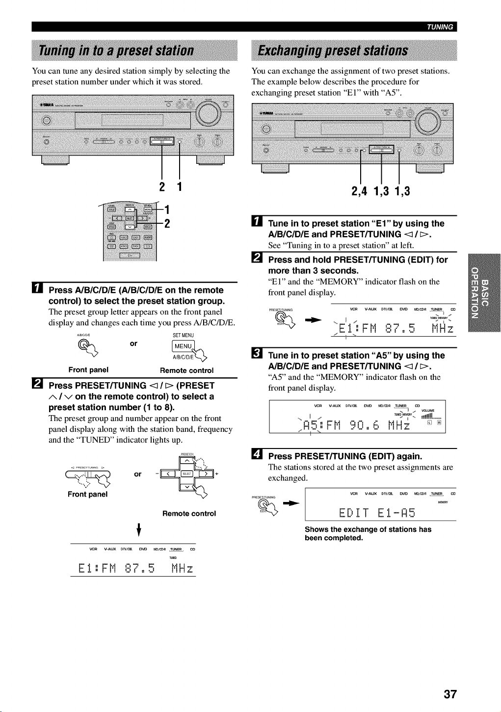
You can tune any desired station simply by selecting the
preset station number under which it was stored.
iqi'lli'l•
You can exchange the assignment of two preset stations.
The example below describes the procedure for
exchanging preset station "El" with "A5".
2 1 2,4 1,3 1,3
[]
[]
[]
P_4
Press A/B/C/D/E (AIBICIDIE on the remote
control) to select the preset station group.
The preset group letter appears on the front panel
display and changes each time you press A/B/C/DR.
_/C,D,E SETMENU
Front panel Remote control
Press PRESET/TUNING <1 /[> (PRESET
A/Von the remote control) to select a
preset station number (1 to 8).
The preset group and number appear on the front
panel display along with the station band, frequency
and the "TUNED" indicator lights up.
_RESET,C_
or - *
Front panel
Remote control
!
VCR V-AUX [TIV/CE_L D_23 ND/CDII TUNER CD
E..L,, F t! ,::,,",, ,., t'!H'z
[]
Tune in to preset station "El" by using the
A/B/C/DIE and PRESET/TUNING <_ / _>.
See "Tuning in to a preset station" at left.
Press and hold PRESET/TUNING (EDIT) for
more than 3 seconds.
"El" and the "MEMORY" indicator flash on the
front panel display.
pRESET/TUNiNG YeN V-AUX _W/C_ O_ _/_ TUNER CD
H/;,-
"F''I',:F H::::,'7..!:'] l',iN '._,'
/......................
Tune in to preset station "A5" by using the
A/B/C/DIE and PRESET/TUNING <_ /_>.
"A5" and the "MEMORY" indicator flash on the
front panel display.
vcn V-AUX _W/CBL OVO MD/C_ TU_ CO
,_ II /r_%_i_'. _l!!!!!!!!........
f't=._,, _.=M ;:.5¢'_ _:: hfLJ-,. [] []
/* *11-% *.................
[] Press PRESET/TUNING (EDIT) again.
The stations stored at the two preset assignments are
exchanged.
VCR V-AUX O-W/C__ OVD MD/CC-R TUNER CD
M_
E[;,! ! E :[-R 5
Shews the exchange of stations has
been completed.
37
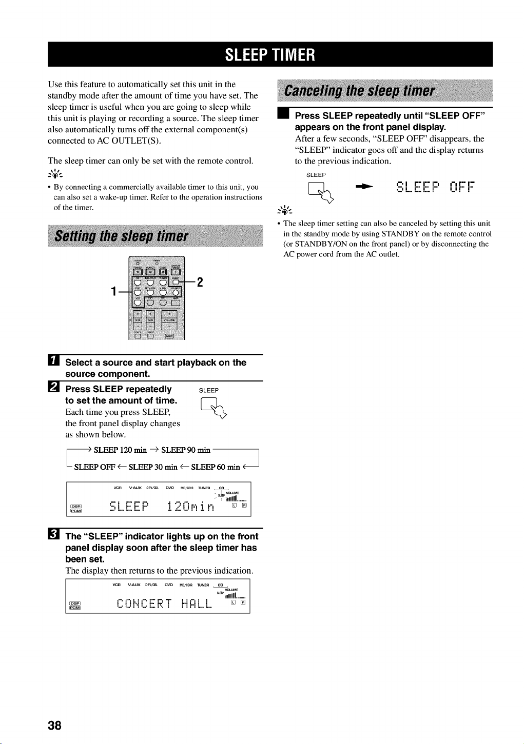
Use this feature to automatically set this unit in the
standby mode after the amount of time you have set. The
sleep timer is useful when you are going to sleep while
this unit is playing or recording a source. The sleep timer
also automatically turns off the external component(s)
connected to AC OUTLET(S).
The sleep timer can only be set with the remote control.
_%-
• By connecting a commercially available timer to this unit, you
can also set a wake-up timer. Refer to the operation instructions
of the timer.
•Press SLEEP repeatedly until "SLEEP OFF"
appears on the front panel display.
After a few seconds, "SLEEP OFF' disappears, the
"SLEEP" indicator goes off and the display returns
to the previous indication.
SLEEP
_i-'l r'= r'= r=i ,=', r'= I'-
•-: L.. "7Ei" i..i "" r"
_.,$,.
• The sleep timer setting can also be canceled by setting this unit
in the standby mode by using STANDBY on the remote control
(or STANDBY/ON on the front panel) or by disconnecting the
AC power cord from the AC outlet.
[] Select a source and start playback on the
source component.
[] Press SLEEP repeatedly SLEEP
to set the amount of time. [_-]_
Each time you press SLEEP,
the front panel display changes
as shown below.
ooo
VCR V-AUX &W/(28_ OVO MD/_4_ TUNER CO
VOLUME
_i!!!!!!!!........
:q1 F F F' I ":'l"ir,'_i F_ []
...... aL, ......
[] The "SLEEP" indicator lights up on the front
panel display soon after the sleep timer has
been set.
The display then returns to the previous indication.
VCR V-AUX _TV/cBL DVD MB/CD_ TUNEn CD
VOLU_
_ ,!!!!!!!!........
PI'I_._I"E'E;'_' _..t1"1] ][] %
38
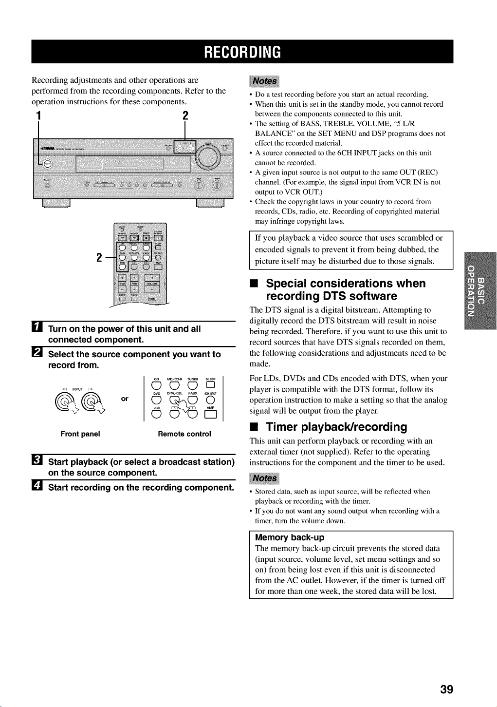
Recording adjustments and other operations are
performed from the recording components. Refer to the
operation instructions for these components.
1 2
2
I_1 Turn on the power of this unit and all
connected component.
[] Select the source component you want to
record from.
or
MD/C_ VUNER S_EEP
OOD
Front panel Remote control
Start playback (or select a broadcast station)
on the source component.
[] Start recording on the recording component.
• Do a test recording before you start an actual recording.
• When this unit is set in the standby mode, you cannot record
between the components connected to this unit.
• The setting of BASS, TREBLE, VOLUME, "5 L/R
BALANCE" on the SET MENU and DSP programs does not
effect the recorded material.
• A source connected to the 6CH INPUT jacks on this unit
cannot be recorded.
• A given input source is not output to the same OUT (REC)
channel. (For example, the signal input from VCR IN is not
output to VCR OUT.)
• Check the copyright laws in your country to record from
records, CDs, radio, etc. Recording of copyrighted material
may infringe copyright laws.
If you playback a video source that uses scrambled or
encoded signals to prevent it from being dubbed, the
picture itself may be disturbed due to those signals.
•Special considerations when
recording DTS software
The DTS signal is a digital bitstream. Attempting to
digitally record the DTS bitstream will result in noise
being recorded. Therefore, if you want to use this unit to
record sources that have DTS signals recorded on them,
the following considerations and adjustments need to be
made.
For LDs, DVDs and CDs encoded with DTS, when your
player is compatible with the DTS format, follow its
operation instruction to make a setting so that the analog
signal will be output from the player.
•Timer playback/recording
This unit can perform playback or recording with an
external timer (not supplied). Refer to the operating
instructions for the component and the timer to be used.
• Stored data, such as input source, will be reflected when
playback or recording with the timer.
• If you do not want any sound output when recording with a
timer, turn the volume down.
Memory back-up
The memory back-up circuit prevents the stored data
(input source, volume level, set menu settings and so
on) from being lost even if this unit is disconnected
from the AC outlet. However, if the timer is turned off
for more than one week, the stored data will be lost.
39

The SET MENU consists of 10 items including the
speaker mode setting. Choose the appropriate item and
adjust or select the values as necessary.
_%-
• You can adjust the items on the SET MENU while playing a
source.
Items Initial settings
1 SPEAKER SET
A CENTER LRG (large)
B MAIN LARGE
C REAR LR LRG (large)
D BASS BOTH
E MAIN Lv Nrm (Normal)
2 LFE LEVEL SP/HP 0 dB
3 SP DLYTIME 0ms
4 D. RANGE SP/HP MAX
5L/R BALANCE 0 dB for L_
6 HPTONE CTRL BASS/TRBL 0 dB
7 I/O ASSIGN
I RX-V530 I
A(component video input)
B(optical output)
C(optical input)
[A] DVD
[B] D-TV/CBL
(1) MD/CD-R
(2) MD/CD-R
(3) DVD
(4) D-TV/CBL
D(coaxial input) (5) CD
C(optical input) (1) DVD
D(coaxial input) (2) CD
8 INPUT MODE AUTO
9 DISPLAY SET
DIMMER 0
10 MEM. GUARD OFF
• In the descriptions for each item from the following page, the
default setting is indicated in bold.
Adjustment should be made with the remote control.
3,6
5
• Some items require extra steps.
[] Press AMP.
[] Press SET MENU to enter
the SET MENU.
AMP
SET MENU
[] Press A/V repeatedly to ........
_.,.--,,
select the item you want
-_+
to adjust (1 to 10).
• By pressing SET MENU repeatedly, you can select items in the
same order as when pressing v
[] Press < /)once to enter
the setup mode of the
selected item.
The last setting you adjusted
appears on the front panel
display.
Depending on the item, press
A/V to select a sub item.
40
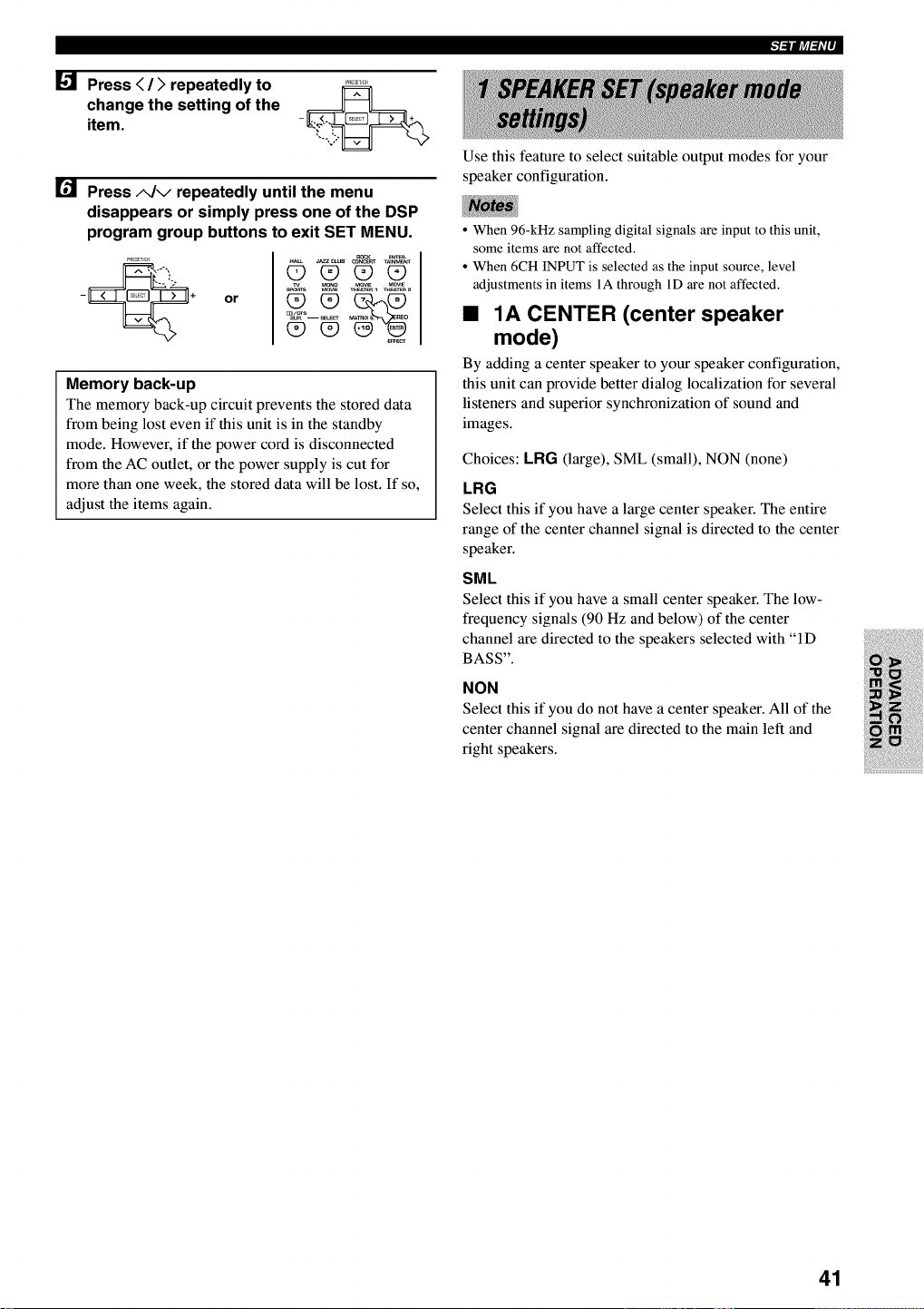
Press < />repeatedly to
change the setting of the
item.
Press A/v repeatedly until the menu
disappears or simply press one of the DSP
program group buttons to exit SET MENU.
or
ROCK _
00_0
Memory back-up
The memory back-up circuit prevents the stored data
from being lost even if this unit is in the standby
mode. However, if the power cord is disconnected
from the AC outlet, or the power supply is cut for
more than one week, the stored data will be lost. If so,
adjust the items again.
t=ilft_l=f='P
Use this feature to select suitable output modes for your
speaker configuration.
• When 96-kHz sampling digital signals are input to this unit,
some items are not affected.
• When 6CH INPUT is selected as the input source, level
adjustments in items 1A through 1D are not affected.
•1A CENTER (center speaker
mode)
By adding a center speaker to your speaker configuration,
this unit can provide better dialog localization for several
listeners and superior synchronization of sound and
images.
Choices: LRG (large), SML (small), NON (none)
LRG
Select this if you have a large center speaker. The entire
range of the center channel signal is directed to the center
speaker.
SML
Select this if you have a small center speaker. The low-
frequency signals (90 Hz and below) of the center
channel are directed to the speakers selected with "ID
BASS".
NON
Select this if you do not have a center speaker. All of the
center channel signal are directed to the main left and
right speakers.
41
•1B MAIN (main speaker mode)
Choices: LARGE, SMALL
LARGE
Select this if you have large main speakers. The entire
range of the main left and fight channel signal is directed
to the main left and right speakers.
SMALL
Select this if you have small main speakers. The low-
frequency signals (90 Hz and below) of the main channel
are directed to the speakers selected with "ID BASS".
•1C REAR LR (rear speaker mode)
Choices: LRG (large), SML (small), NON (none)
LRG
Select this if you have large rear left and fight speakers or
if a rear subwoofer is connected to the rear speakers. The
entire range of the rear channel signal is directed to the
rear left and fight speakers.
SML
Select this if you have small rear left and fight speakers.
The low-frequency signals (90 Hz and below) of the rear
channel are directed to the speakers selected with "ID
BASS".
NON
Select this if you do not have rear speakers.
•This unit is set in the virtual CINEMA DSP mode when you
select NON for "1C REAR LR".
•1D BASS (LFE/bass out mode)
LFE signals carry low-frequency effects when this unit
decodes a Dolby Digital or DTS signal. Low-frequency
signals are defined as 90 Hz and below. The Low-
frequency signals can be directed to both main left and
right speakers, and the subwoofer (subwoofer can be used
for both stereo reproduction and the DSP program).
Choices: SWFR (subwoofer), MAIN, BOTH
SWFR
Select this if you use a subwoofer. The LFE signals are
directed to the subwoofer.
MAIN
Select this if you do not use a subwoofer. The LFE
signals are directed to the main speakers.
BOTH
The LFE signals are directed to the subwoofer. Low-
frequency signals designated to the main channels in
accordance with other speaker mode settings are directed
to both main speakers and a subwoofer.
• When you select MAIN for "ID BASS", the low-frequency
signals (90 Hz and below) of the main channel are directed to
the main speakers even if you select SMALL for the main
speaker mode.
•1E MAIN Lv (main level mode)
Change this setting if you cannot match the output level
of the center, and rear (L/R) speakers with the main
speakers because of unusually high-efficiency
performance from the main speakers.
Choices: Nrm (Normal), -10 dB
Nrm
Select this if you can match the output level of your effect
speakers with that of your main speakers when using the
test tone.
-10 dB
Select this if you cannot match the output level of your
effect speakers with that of your main speakers when
using the test tone.
42
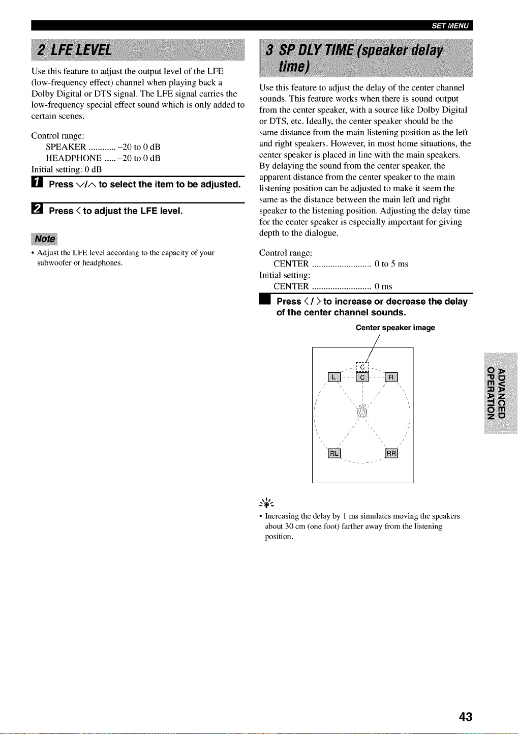
Use this feature to adjust the output level of the LFE
(low-frequency effect) channel when playing back a
Dolby Digital or DTS signal. The LFE signal carries the
low-frequency special effect sound which is only added to
certain scenes.
Control range:
SPEAKER ............ -20 to 0 dB
HEADPHONE ..... -20 to 0 dB
Initial setting: 0 dB
U Press via to select the item to be adjusted.
[] Press < to adjust the LFE level.
•Adjust the LFE level according to the capacity of your
subwoofer or headphones.
Use this feature to adjust the delay of the center channel
sounds. This feature works when there is sound output
from the center speaker, with a source like Dolby Digital
or DTS, etc. Ideally, the center speaker should be the
same distance from the main listening position as the left
and fight speakers. However, in most home situations, the
center speaker is placed in line with the main speakers.
By delaying the sound from the center speaker, the
apparent distance from the center speaker to the main
listening position can be adjusted to make it seem the
same as the distance between the main left and right
speaker to the listening position. Adjusting the delay time
for the center speaker is especially important for giving
depth to the dialogue.
Control range:
CENTER .......................... 0 to 5 ms
Initial setting:
CENTER .......................... 0 ms
•Press < />to increase or decrease the delay
of the center channel sounds.
Center speaker image
r--/
/ S \\ \\ Iii z /' _
i
i
\/
• Increasing the delay by 1 ms simulates moving the speakers
about 30 cm (one foot) farther away from the listening
position.
43
I"l'illt_l_i'l'
Use this feature to adjust the dynamic range. This setting
is effective only when this unit is decoding Dolby Digital
signals.
Choices: MAX, STD (standard), MIN (minimum)
MAX
Select the "MAX" for feature films.
STD
Select the "STD" for general use.
MIN
Select the "MIN" for listening to sources at low volume
levels.
Use this feature to adjust the balance of the output level
from the main left and fight speakers.
Control range: 20 steps for L/R
Initial setting: 0 dB for L/R
•Press )to decrease the output level for the
main left speaker. Press < for the main right
speaker.
Use this feature to adjust the level of the bass and treble
when you use your headphones.
It is possible to assign jacks according to the component
to be used if this unit's COMPONENT VIDEO input jack
or DIGITAL INPUT/OUTPUT jack settings (component
names for jacks) differ from that component. This makes
it possible to change the jack assignment and effectively
connect more components.
Once you assign, you can select that component with
INPUT <z] /D(or the input selector buttons on the
remote control).
• _ 7A CMPNT-V INPUT for
COMPONENT VIDEO INPUT jacks
Choices: [A] DVD, V-AUX, VCR, D-TV/CBL
[B] DVD, V-AUX, VCR, D-TV/CBL
• _ 7B OPTICAL OUT for
OPTICAL OUTPUT jack
Choices: (1) MD/CD-R, CD, V-AUX, VCR,
D-TV/CBL, DVD
•7C OPTICAL IN for OPTICAL
INPUT jacks
Choices: (2) MD/CD-R, CD, V-AUX, VCR,
D-TV/CBL, DVD
(3) MD/CD-R, CD, V-AUX, VCR,
D-TV/CBL, DVD
(4) MD/CD-R, CD, V-AUX, VCR,
D-TV/CBL, DVD
Control range (dB):
BASS ............... -6 to +3
TRBL (treble) .. -6 to +3
Initial setting:
BASS ............... 0 dB
TRBL ............... 0 dB
Choices: (1) MD/CD-R, CD, V-AUX, VCR,
D-TV/CBL, DVD
•7D COAXIAL IN for COAXIAL
INPUT jack
Choices: (5) MD/CD-R, CD, V-AUX, VCR,
D-TV/CBL, DVD
Choices: (2) MD/CD-R, CD, V-AUX, VCR,
D-TV/CBL, DVD
• You cannot select an item more than once for the same type of
jack.
• When you connect a component to both the COAXIAL and
OPTICAL jacks, priority is given to the input signals from the
COAXIAL jack.
44
Use this feature to designate the input mode for sources
connected to the DIGITAL INPUT jacks when you turn
on this unit (see page 25 for details about the input
mode).
Choices: AUTO, LAST
AUTO
Select this to allow this unit to automatically detect the
type of input signal and select the appropriate input mode.
LAST
Select this to set this unit to automatically select the last
input mode used for the respective source.
•DIMMER
You can adjust the brightness of the front panel display.
Control range: -4 to 0
Initial setting: 0
Use this feature to prevent accidental changes to settings
on this unit.
Choices: ON, OFF
Select ON to protect the following features:
•All SET MENU items
• Center, rear speakers, and subwoofer levels
•DSP program parameters
•When this item is set to ON, you cannot use the test tone.
• When this item is set to ON, you cannot select any other SET
MENU items.
45
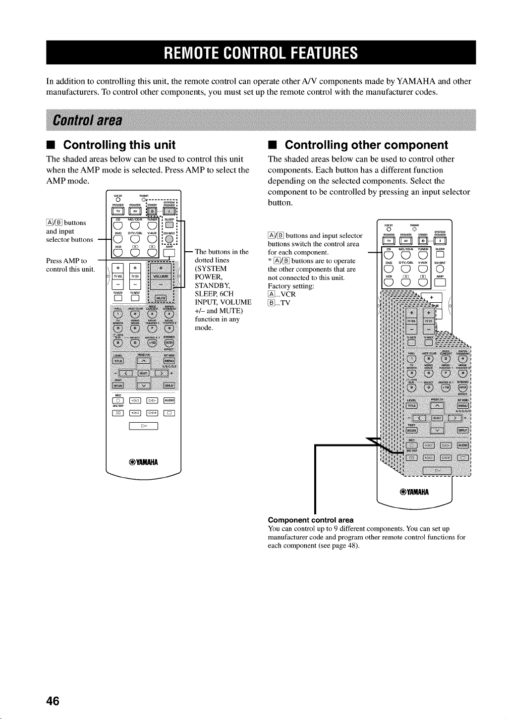
In addition to controlling this unit, the remote control can operate other A/V components made by YAMAHA and other
manufacturers. To control other components, you must set up the remote control with the manufacturer codes.
• Controlling this unit
The shaded areas below can be used to control this unit
when the AMP mode is selected. Press AMP to select the
AMP mode.
@[_] buttons
and input
selector buttons --
Press AMP to
control this unit.
_ E53 _ NN
_ EZ3 r_q r_q
@YAMAHA
in the
dotted lines
(SYSTEM
POWER,
STANDBY,
SLEER 6CH
INPUT, VOLUME
+/- and MUTE)
function in any
mode.
•Controlling other component
The shaded areas below can be used to control other
components. Each button has a different function
depending on the selected components. Select the
component to be controlled by pressing an input selector
button.
_/_B] buttons and input selector
buttons switch the control area
for each component.
* _ff buttons are to operate
the other components that are
not connected to this unit.
Factory setting:
_...VCR
[_BI...TV
.....
©© Y5
Component control area
You can control up to 9 different components. You can set up
manufacturer code and program other remote control functions for
each component (see page 48).
46
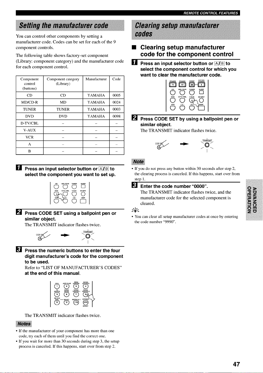
_t_fe_E_E_e]AvEE_e]IE_T_WlEI_i_
You can control other components by setting a
manufacturer code. Codes can be set for each of the 9
component controls.
The following table shows factory-set component
(Library: component category) and the manufacturer code
for each component control.
Component Component category Manufacturer Code
control (Library)
(buttons)
CD CD YAMAHA 0005
MD/CD-R MD YAMAHA 0024
TUNER TUNER YAMAHA 0003
DVD DVD YAMAHA 0098
D-TV/CBL - - -
V-AUX - - -
VCR - - -
A - - -
g - - -
I_1 Press an input selector button or _to
select the component you want to set up.
•Clearing setup manufacturer
code for the component control
[] Press an input selector button or _to
select the component control for which you
want to clear the manufacturer code.
_ovw_ pOWER _N_ _ovw_
MD/C_R mN_ S_P
OOD
c_w/ceL v-aux _. _
[] Press CODE SET by using a ballpoint pen or
similar object.
The TRANSMIT indicator flashes twice.
oo_ .TyA4SM!_
[]
[]
_v._x _
©i5
Press CODE SET using a ballpoint pen or
similar object.
The TRANSMIT indicator flashes twice.
co_(_ ,._RA_SM_
Press the numeric buttons to enter the four
digit manufacturer's code for the component
to be used.
Refer to "LIST OF MANUFACTURER'S CODES"
at the end of this manual.
The TRANSMIT indicator flashes twice.
• If you do not press any button within 30 seconds after step 2,
the clearing process is canceled. If this happens, start over from
step 1.
[] Enter the code number"0000".
The TRANSMIT indicator flashes twice, and the
manufacturer code for the selected component is
cleared.
,4,
• You can clear all setup manufacturer codes at once by entering
the code number "9990".
• If the manufacturer of your component has more than one
code, try each of them until you find the correct one.
• If you wait for more than 30 seconds during step 3, the setup
process is canceled. If this happens, start over from step 2.
47
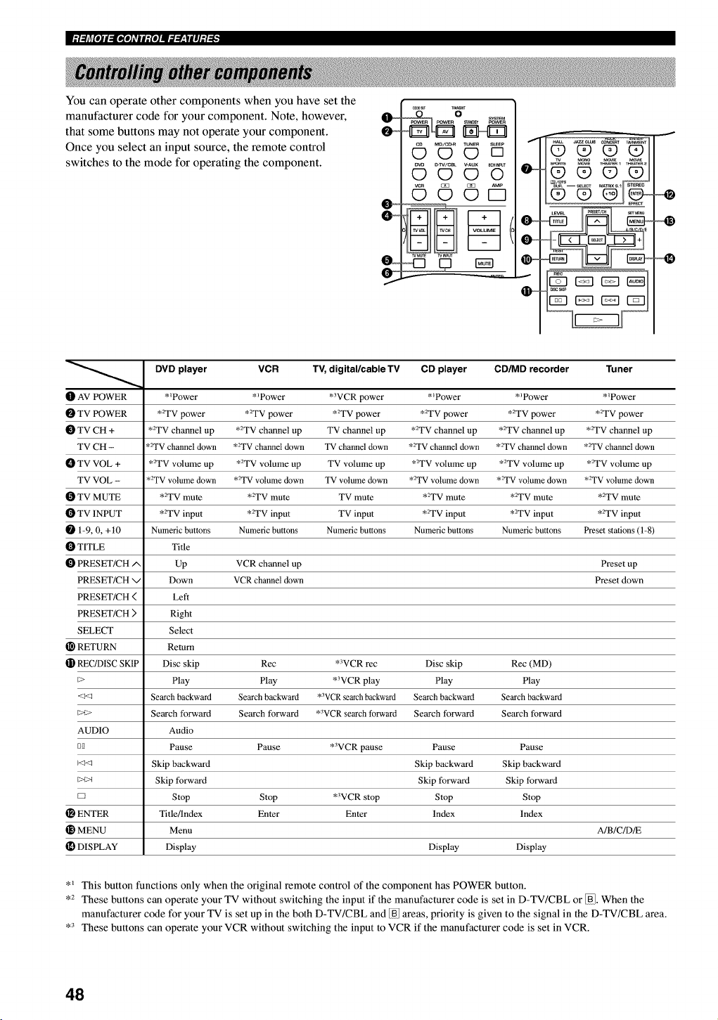
I,:t:FAr/[l]l.,IGJ[l]L*qlt_,{l]ll.7._r:|ll];t_
You can operate other components when you have set the
manufacturer code for your component. Note, however,
that some buttons may not operate your component.
Once you select an input source, the remote control
switches to the mode for operating the component.
_,x_/c_ TUNER su_Ep
OO[]
_w _VWCBL _AUX _c_
0©©0
AMP
©©©D
wMm_ w_puT
O
O_
DVD player VCR TV, digital/cable TV CD player CD/MD recorder Tuner
t_ AV POWER *_Power *_Power *3VCR power *_Power * _Power *_Power
TV POWER *2TV power *2TV power *2TV power *2TV power *2TV power *2TV power
TV CH + *2TV channel up *2TV channel up TV channel up *2TV channel up *2TV channel up *2TV channel up
TV CH - *2TV channel down *2TV channel down TV channel down *2TV channel down *2TV channel down *2TV channel down
TV VOL + *2TV volume up *2TV volume up TV volume up *2TV volume up *2TV volume up *2TV volume up
TV VOL - *2TV volume down *2TV volume down TV volume down *2TV volume down *2TV volume down *2TV volume down
TV MUTE *2TV mute *2TV mute TV mute *2TV mute *2TV mute *2TV mute
TV INPUT *2TV input *2TV input TV input *2TV input *2TV input *2TV input
1-9, 0, +t0 Numeric buttons Numeric buttons Numeric buttons Numeric buttons Numeric buttons Preset stations (1-8)
TITLE Title
PRESET/CH/', Up VCR channel up Preset up
PRESET/CH v Down VCR channel down Preset down
PRESET/CH ( Left
PRESET/CH ) Right
SELECT Select
RETURN Return
REC/D1SC SKIP Disc skip Rec *WCR rec Disc skip Rec (MD)
_> Play Play *3VCR play Play Play
<_ Search backward Search backward *3VCRsearchbackward Search backward Search backward
_>t> Search forward Search forward *WCR search forward Search forward Search forward
AUDIO Audio
DI1 Pause Pause *3VCR pause Pause Pause
Skip backward Skip backward Skip backward
_>t>_ Skip forward Skip forward Skip forward
D Stop Stop *3VCR stop Stop Stop
ENTER Title/Index Enter Enter Index Index
MENU Menu A/B/C/D/E
[D DISPLAY Display Display Display
*_ This button functions only when the original remote control of the component has POWER button.
,2 These buttons can operate your TV without switching the input if the manufacturer code is set in D-TV/CBL or _. When the
manufacturer code for your TV is set up in the both D-TV/CBL and _ areas, priority is given to the signal in the D-TV/CBL area.
,3 These buttons can operate your VCR without switching the input to VCR if the manufacturer code is set in VCR.
48
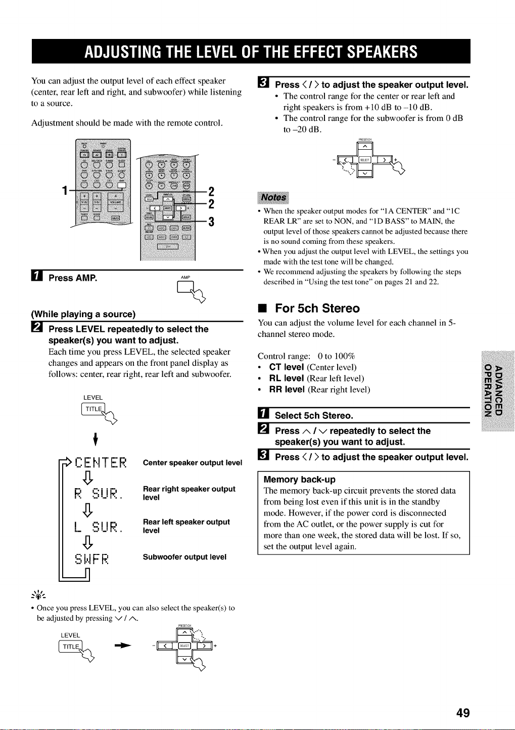
You can adjust the output level of each effect speaker
(center, rear left and fight, and subwoofer) while listening
to a source.
Adjustment should be made with the remote control.
[] Press < />to adjust the speaker output level.
• The control range for the center or rear left and
right speakers is from +10 dB to -10 dB.
• The control range for the subwoofer is from 0 dB
to -20 dB.
PRESET,C_
[] Press AMP. AMP
Q
(While playing a source)
_._ Press LEVEL repeatedly to select the
speaker(s) you want to adjust.
Each time you press LEVEL, the selected speaker
changes and appears on the front panel display as
follows: center, rear fight, rear left and subwoofer.
LEVEL
:_ O E _"I'r E I:'3. Center speaker output level
g
Rear right speaker output
F;! !ii;i.iR level
Rear left speaker output
LS!_!F;! level
!i; i.'.iF F;.'. Subwoofer output level
• When the speaker output modes for "IA CENTER" and "1C
REAR LR" are set to NON, and "ID BASS" to MAIN, the
output level of those speakers cannot be adjusted because there
is no sound coming from these speakers.
• When you adjust the output level with LEVEL, the settings you
made with the test tone will be changed.
• We recommend adjusting the speakers by following the steps
described in "Using the test tone" on pages 21 and 22.
•For 5ch Stereo
You can adjust the volume level for each channel in 5-
channel stereo mode.
Control range: 0 to 100%
•CT level (Center level)
•RL level (Rear left level)
•RR level (Rear fight level)
[] Select 5ch Stereo.
[] Press A/Vrepeatedly to select the
speaker(s) you want to adjust.
[] Press < / > to adjust the speaker output level.
Memory back-up
The memory back-up circuit prevents the stored data
from being lost even if this unit is in the standby
mode. However, if the power cord is disconnected
from the AC outlet, or the power supply is cut for
more than one week, the stored data will be lost. If so,
set the output level again.
• Once you press LEVEL, you can also select the speaker(s) to
be adjusted by pressing v /A.
P_ES:TSCH
LEVEL
(_ _ - +
49
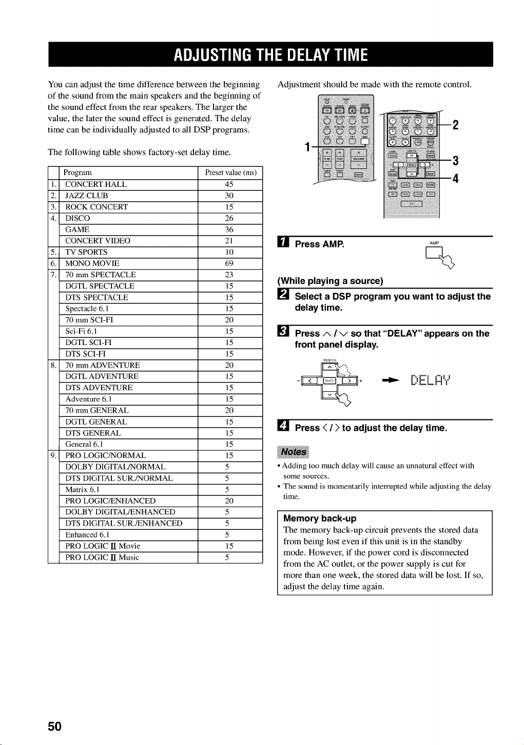
You can adjust the time difference between the beginning
of the sound from the main speakers and the beginning of
the sound effect from the rear speakers. The larger the
value, the later the sound effect is generated. The delay
time can be individually adjusted to all DSP programs.
The following table shows factory-set delay time.
Program Preset value (ms)
1. CONCERT HALL 45
2. JAZZ CLUB 30
3. ROCK CONCERT 15
4. DISCO 26
GAME 36
CONCERT VIDEO 21
5. TV SPORTS 10
6. MONO MOVIE 69
7. 70 mm SPECTACLE 23
DGTL SPECTACLE 15
DTS SPECTACLE 15
Spectacle 6.1 15
70 mm SCI-FI 20
Sci-Fi 6.1 15
DGTL SCI-FI 15
DTS SCI-FI 15
8. 70 mm ADVENTURE 20
DGTL ADVENTURE 15
DTS ADVENTURE 15
Adventure 6.1 15
70 mm GENERAL 20
DGTL GENERAL 15
DTS GENERAL 15
General 6.1 15
9. PRO LOGIC/NORMAL 15
DOLBY DIGITAL/NORMAL 5
DTS DIGITAL SUR./NORMAL 5
Matrix 6.1 5
PRO LOGIC/ENHANCED 20
DOLBY DIGITAL/ENHANCED 5
DTS DIGITAL SUR./ENHANCED 5
Enhanced 6.1 5
PRO LOGIC lI Movie 15
PRO LOGIC lI Music 5
Adjustment should be made with the remote control.
U Press AMP. AMP
Q
(While playing a source)
[] Select a DSP program you want to adjust the
delay time.
[] Press A/vso that "DELAY" appears on the
front panel display.
•"_ L)[::.L..FI"i
[] Press < /)to adjust the delay time.
• Adding too much delay will cause an unnatural effect with
some sources.
• The sound is momentarily interrupted while adjusting the delay
time.
Memory back-up
The memory back-up circuit prevents the stored data
from being lost even if this unit is in the standby
mode. However, if the power cord is disconnected
from the AC outlet, or the power supply is cut for
more than one week, the stored data will be lost. If so,
adjust the delay time again.
5O
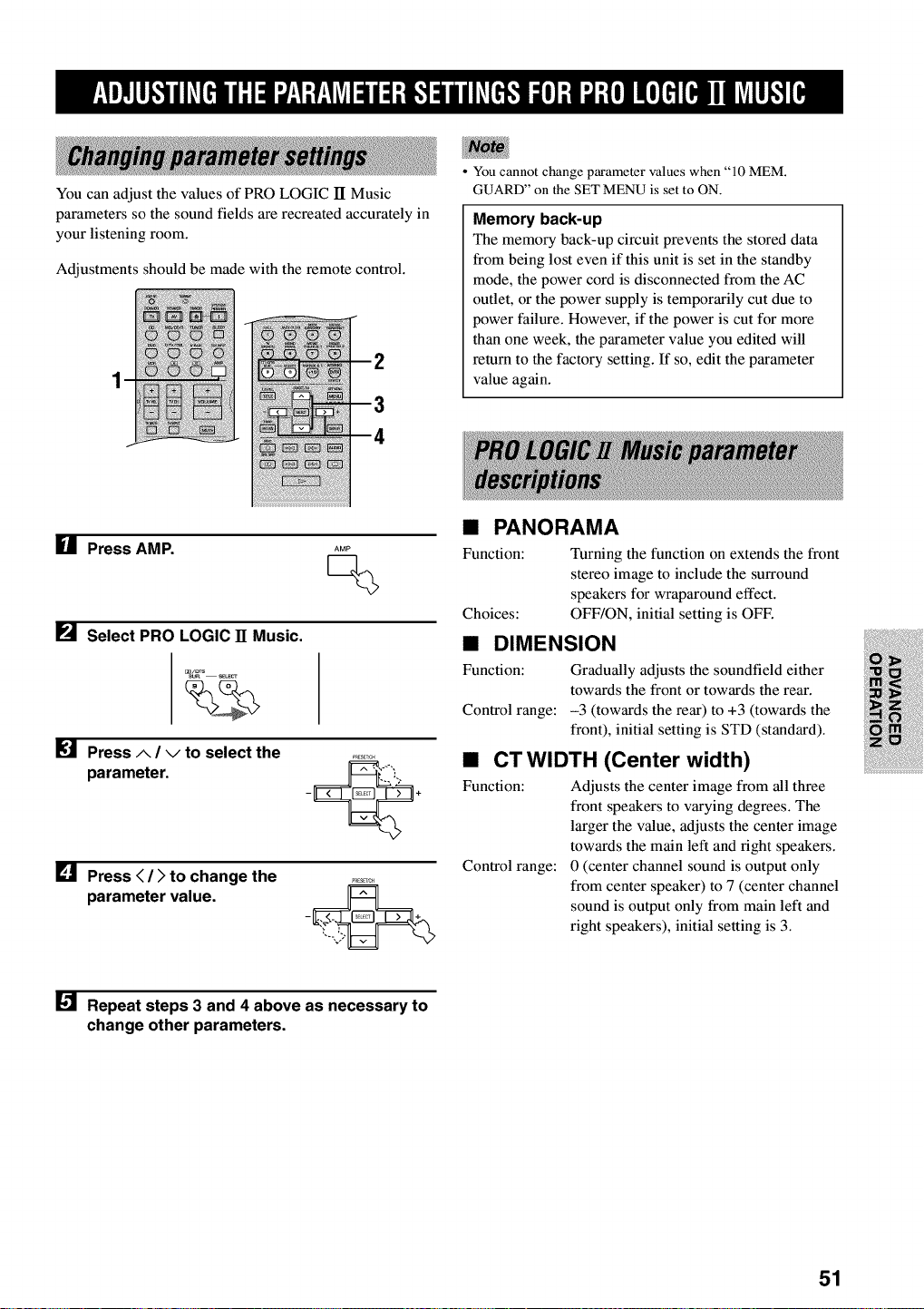
You can adjust the values of PRO LOGIC lI Music
parameters so the sound fields are recreated accurately in
your listening room.
Adjustments should be made with the remote control.
You cannot change parameter values when "10 MEM.
GUARD" on the SET MENU is set to ON.
Memory back-up
The memory back-up circuit prevents the stored data
from being lost even if this unit is set in the standby
mode, the power cord is disconnected from the AC
outlet, or the power supply is temporarily cut due to
power failure. However, if the power is cut for more
than one week, the parameter value you edited will
return to the factory setting. If so, edit the parameter
value again.
HPress AMP. AMP
Q
_._ Select PRO LOGIC 11 Music.
[] Press A/vto select the
parameter.
[] Press < /)to change the
parameter value.
• PANORAMA
Function: Turning the function on extends the front
stereo image to include the surround
speakers for wraparound effect.
Choices: OFF/ON, initial setting is OFF.
•DIMENSION
Function: Gradually adjusts the soundfield either
towards the front or towards the rear.
Control range: -3 (towards the rear) to +3 (towards the
front), initial setting is STD (standard).
•CTWIDTH (Center width)
Function: Adjusts the center image from all three
front speakers to varying degrees. The
larger the value, adjusts the center image
towards the main left and fight speakers.
Control range: 0 (center channel sound is output only
from center speaker) to 7 (center channel
sound is output only from main left and
right speakers), initial setting is 3.
[] Repeat steps 3 and 4 above as necessary to
change other parameters.
51
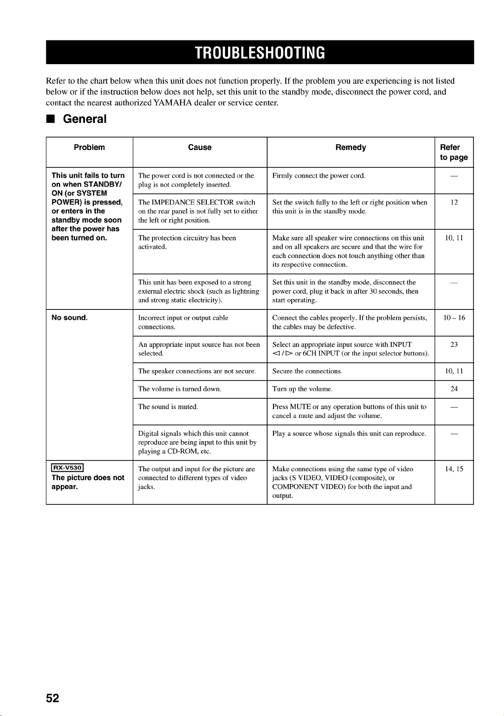
Refer to the chart below when this unit does not function properly. If the problem you are experiencing is not listed
below or if the instruction below does not help, set this unit to the standby mode, disconnect the power cord, and
contact the nearest authorized YAMAHA dealer or service center.
•General
Problem Cause Remedy Refer
to page
This unit fails to turn The power cord is not connected or the Firmly connect the power cord.
on when STANDBY/ plug is not completely inserted.
ON (or SYSTEM
POWER) is pressed, The IMPEDANCE SELECTOR switch Set the switch fully to the left or right position when 12
or enters in the on the rear panel is not fully set to either this unit is in the standby mode.
standby mode soon the left or right position.
after the power has
been turned on. The protection circuitry has been Make sure all speaker wire connections on this unit 10, 11
activated, and on all speakers are secure and that the wire for
each connection does not touch anything other than
its respective connection.
This unit has been exposed to a strong Set this unit in the standby mode, disconnect the --
external electric shock (such as lightning power cord, plug it back in after 30 seconds, then
and strong static electricity), start operating.
NO sound. Incorrect input or output cable Connect the cables properly. If the problem persists, 10 - 16
connections, the cables may be defective.
An appropriate input source has not been Select an appropriate input source with INPUT 23
selected. <3 /I:> or 6CH INPUT (or the input selector buttons).
The speaker connections are not secure. Secure the connections. 10, 11
The volume is turned down. Turn up the volume. 24
The sound is muted. Press MUTE or any operation buttons of this unit to --
cancel a mute mad adjust the volume.
Digital signals which this unit cannot Play a source whose signals this unit can reproduce. --
reproduce are being input to this unit by
playing a CD-ROM, etc.
The output and input for the picture are Make connections using the same type of video 14, 15
The picture does not connected to different types of video jacks (S VIDEO, VIDEO (composite), or
appear, jacks. COMPONENT VIDEO) for both the input and
output.
52
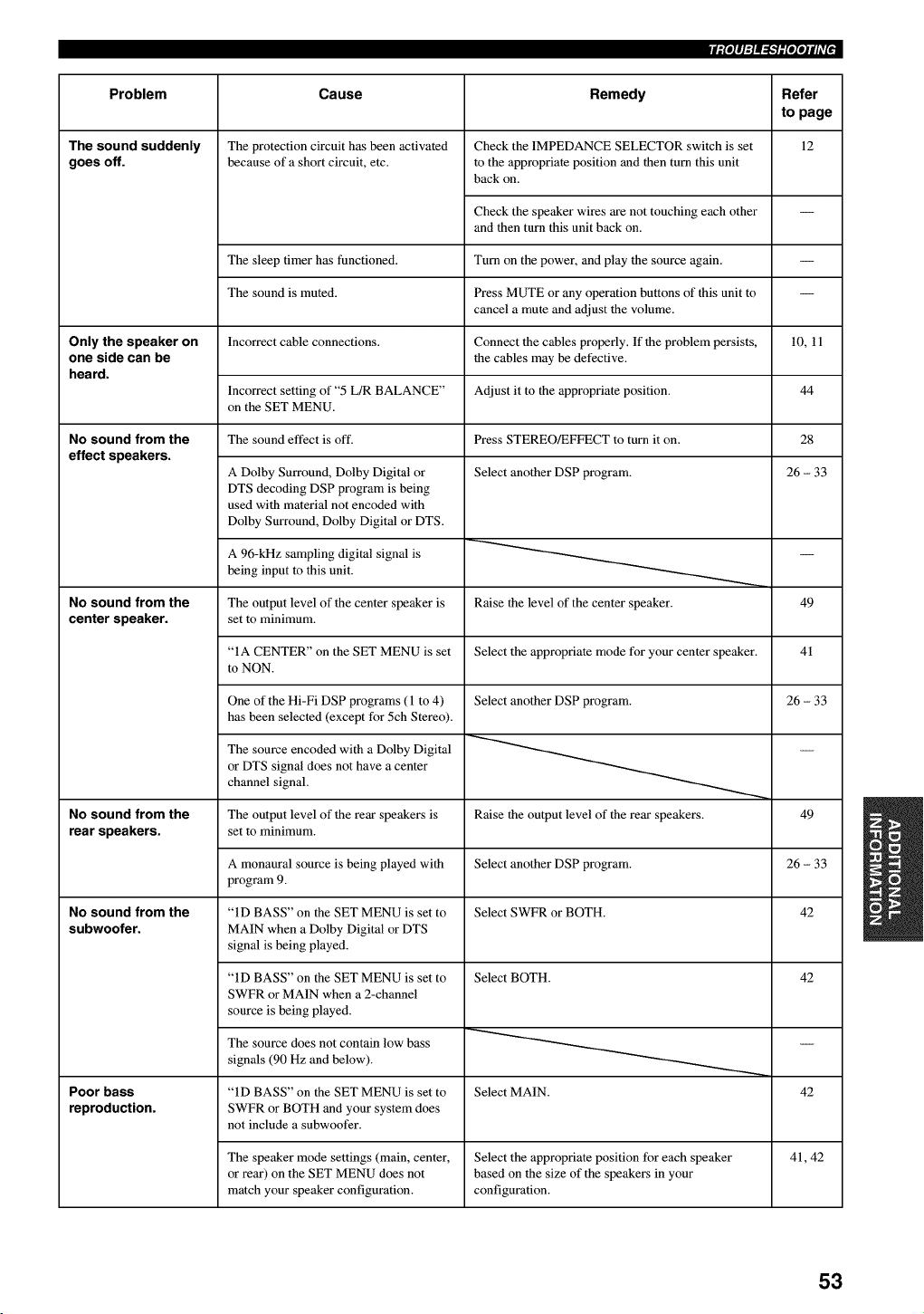
iiPlq:l_-Wlqqili'l _
Problem Cause Remedy Refer
to page
12
The sound suddenly
goes off.
Only the speaker on
one side can be
heard.
No sound from the
effect speakers.
No sound from the
center speaker.
No sound from the
rear speakers.
No sound from the
subwoofer.
Poor bass
reproduction.
The protection circuit has been activated Check the IMPEDANCE SELECTOR switch is set
because of a short circuit, etc. to the appropriate position and then turn this unit
back on.
Check the speaker wires are not touching each other
and then turn this unit back on.
The sleep timer has functioned. Turn on the power, and play the source again.
The sound is muted. Press MUTE or any operation buttons of this unit to
cancel a mute and adjust the volume.
Incorrect cable connections. Connect the cables properly. If the problem persists, 10, 11
the cables may be defective.
Adjust it to the appropriate position.Incorrect setting of "5 L/R BALANCE"
on the SET MENU.
Press STEREO/EFFECT to turn it on.The sound effect is off.
A Dolby Surround, Dolby Digital or
DTS decoding DSP program is being
used with material not encoded with
Dolby Surround, Dolby Digital or DTS.
A 96-kHz sampling digital signal is
being input to this unit.
Select another DSP program.
Raise the level of the center speaker.The output level of the center speaker is
set to minimum.
"IA CENTER" on the SET MENU is set Select the appropriate mode for your center speaker.
to NON.
One of the Hi-Fi DSP programs (l to 4)
has been selected (except for 5ch Stereo).
The source encoded with a Dolby Digital
or DTS signal does not have a center
channel signal.
Select another DSP program.
44
The output level of the rear speakers is
set to minimum.
A monaural source is being played with
program 9.
"ID BASS" on the SET MENU is set to
MAIN when a Dolby Digital or DTS
signal is being played.
"ID BASS" on the SET MENU is set to
SWFR or MAIN when a 2-channel
source is being played.
The source does not contain low bass
signals (90 Hz and below).
28
26 - 33
49
41
26 - 33
"ID BASS" on the SET MENU is set to
SWFR or BOTH and your system does
not include a subwoofer.
Raise the output level of the rear speakers. 49
Select another DSP program. 26 - 33
Select SWFR or BOTH. 42
Select BOTH. 42
Select MAIN. 42
The speaker mode settings (main, center, Select the appropriate position for each speaker
or rear) on the SET MENU does not based on the size of the speakers in your
match your speaker configuration, configuration.
41, 42
53
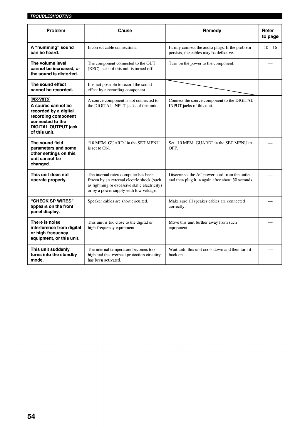
Problem
A"humming" sound
can be heard.
The volume level
cannot be increased, or
the sound is distorted.
The sound effect
cannot be recorded.
A source cannot be
recorded by a digital
recording component
connected to the
DIGITAL OUTPUT jack
of this unit.
The sound field
parameters and some
other settings on this
unit cannot be
changed.
This unit does not
operate properly.
"CHECK SP WIRES"
appears on the front
panel display.
There is noise
interference from digital
or high-frequency
equipment, or this unit.
Cause
Incorrect cable connections.
The component connected to the OUT
(REC) jacks of this unit is turned off.
It is not possible to record the sound
effect by a recording component.
A source component is not connected to
the DIGITAL INPUT jacks of this unit.
"10 MEM. GUARD" in the SET MENU
is set to ON.
The internal microcomputer has been
frozen by an external electric shock (such
as lightning or excessive static electricity)
or by a power supply with low voltage.
Speaker cables are short circuited.
This unit is too close to the digital or
high-frequency equipment.
Remedy
Firmly connect the audio plugs. If the problem
persists, the cables may be defective.
Turn on the power to the component.
Connect the source component to the DIGITAL
INPUT jacks of this unit.
Set "10 MEM. GUARD" in the SET MENU to
OFF.
Disconnect the AC power cord from the outlet
and then plug it in again after about 30 seconds.
Make sure all speaker cables are connected
correctly.
Move this unit further away from such
equipment.
This unit suddenly The internal temperature becomes too Wait until this unit cools down and then turn it --
turns into the standby high and the overheat protection circuitry back on.
mode. has been activated.
Refer
to page
10- 16
54
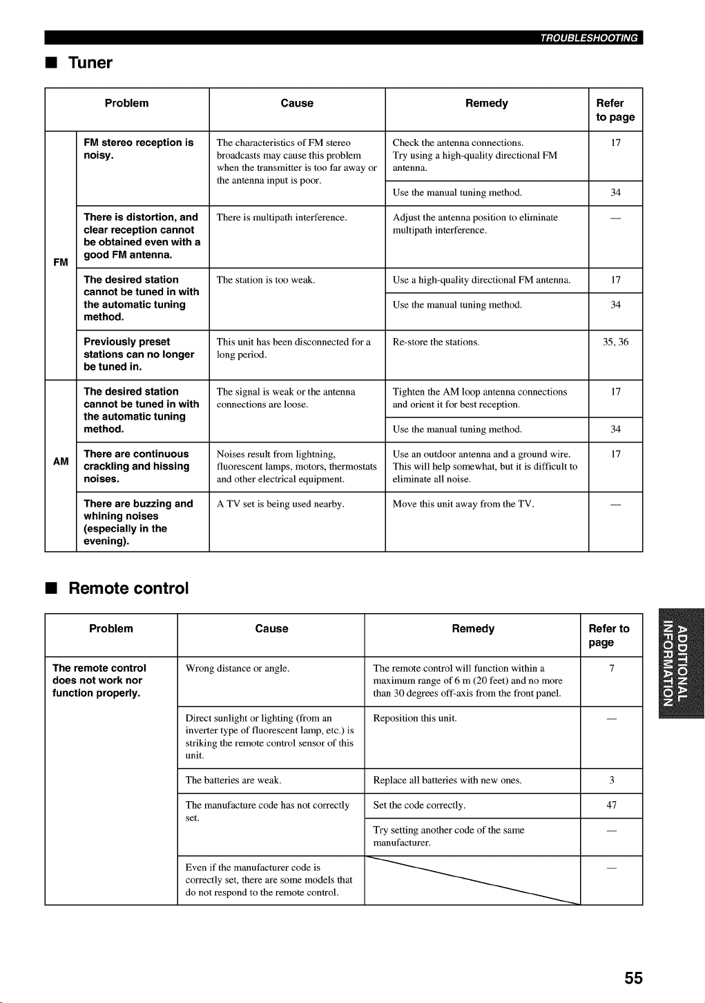
•Tuner
iil'lq:l_-Wl'l'tili'l _
FM
AM
Problem Cause Remedy Refer
to page
FM stereo reception is 17
noisy.
There is distortion, and
clear reception cannot
be obtained even with a
good FM antenna.
The desired station
cannot be tuned in with
the automatic tuning
method.
Previously preset
stations can no longer
be tuned in.
The desired station
cannot be tuned in with
the automatic tuning
method.
There are continuous
crackling and hissing
noises.
There are buzzing and
whining noises
(especially in the
evening).
The characteristics of FM stereo
broadcasts may cause this problem
when the transmitter is too far away or
the antenna input is poor.
There is multipath interference.
The station is too weak.
This unit has been disconnected for a
long period.
The signal is weak or the antenna
connections are loose.
Noises result from lightning,
fluorescent lamps, motors, thermostats
and other electrical equipment.
A TV set is being used nearby.
Check the antenna connections.
Try using a high-quality directional FM
antenna.
Use the manual tuning method.
Adjust the antenna position to eliminate
multipath interference.
34
Use a high-quality directional FM antenna. 17
Use the manual tuning method. 34
Re-store the stations. 35, 36
Tighten the AM loop antenna connections
and orient it for best reception.
Use the manual tuning method.
Use an outdoor antenna mad a ground wire.
This will help somewhat, but it is difficult to
eliminate all noise.
Move this unit away from the TV.
17
34
17
•Remote control
Problem Cause Remedy Refer to
page
The remote control Wrong distance or angle. The remote control will function within a 7
does not work nor maximum range of 6 m (20 feet) and no more
function properly, than 30 degrees off-axis from the front panel.
Direct sunlight or lighting (from an Reposition this unit.
inverter type of fluorescent lamp, etc.) is
striking the remote control sensor of this
unit.
The batteries are weak. Replace all batteries with new ones.
The manufacture code has not correctly Set the code correctly.
set.
Even if the manufacturer code is
correctly set, there are some models that
do not respond to the remote control.
Try setting another code of the same
manufacturer.
3
47
55
•Dolby Surround
Dolby Surround uses a 4 channel analog recording system
to reproduce realistic and dynamic sound effects: 2 main
left and right channels (stereo), a center channel for
dialog (monaural), and a rear channel for special sound
effects (monaural). The rear channel reproduces sound
within a narrow frequency range.
Dolby Surround is widely used with nearly all video tapes
and laser discs, and in many TV and cable broadcasts as
well. The Dolby Pro Logic decoder built into this unit
employs a digital signal processing system that
automatically stabilizes the volume on each channel to
enhance moving sound effects and directionality.
•Oolby Digital
Dolby Digital is a digital surround sound system that
gives you completely independent multi-channel audio.
With 3 front channels (left, center, and right), and 2 rear
stereo channels, Dolby Digital provides 5 full-range audio
channels. With an additional channel especially for bass
effects, called LFE (low frequency effect), the system has
a total of 5.1 channels (LFE is counted as 0.1 channel).
By using 2-channel stereo for the rear speakers, more
accurate moving sound effects and surround sound
environment are possible than with Dolby Surround. The
wide dynamic range (from maximum to minimum
volume) reproduced by the 5 full-range channels and the
precise sound orientation generated using digital sound
processing provide listeners with previously unheard of
excitement and realism.
With this unit, any sound environment from monaural up
to a 5.1-channel configuration can be freely selected for
your enjoyment.
•Matrix 6.1
The unit incorporates Matrix 6.1 decoder for Dolby
Digital and DTS multi-channel software that enables 6.1-
channel reproduction by adding the rear center channel to
existing 5.1-channel format. (The rear center channel is
created from rear left and right channels, and outputted
from virtual rear center speaker.) With this additional
channel, you can experience more dynamic and realistic
moving sound especially with scenes with "fly-over" and
"fly-around" effects.
•Dolby Pro Logic 11
Dolby Pro Logic II is an improved technique used to
decode vast numbers of existing Dolby Surround
softwares. This new technology enables a discrete 5-
channel playback with 2 main left and right channels, 1
center channel, and 2 rear left and right channels (instead
of only 1 rear channel for conventional Pro Logic
technology). A music mode is also available for 2-channel
sources in addition to the movie mode.
•DTS (Digital Theater Systems)
Digital Surround
DTS digital surround was developed to replace the analog
soundtracks of movies with a 6-channel digital sound
track, and is now rapidly gaining popularity in movie
theaters around the world. Digital Theater Systems Inc.
has developed a home theater system so that you can
enjoy the depth of sound and natural spatial
representation of DTS digital surround in your home.
This system produces practically distortion-free 6-channel
sound (technically, a left, right and center channels, 2 rear
channels, plus an LFE 0.1 channel as a subwoofer, for a
total of 5.1 channels).
•LFE 0.1 channel
This channel is for the reproduction of low bass signals.
The frequency range for this channel is 20 Hz to 120 Hz.
This channel is counted as 0.1 because it only enforces a
low frequency range compared to the full-range
reproduced by the other 5 channels in a Dolby Digital or
DTS 5.1 channel systems.
•CINEMA DSP
Since the Dolby Surround and DTS systems were
originally designed for use in movie theaters, their effect
is best felt in a theater having many speakers and
designed for acoustic effects. Since home conditions,
such as room size, wall material, number of speakers, and
so on, can differ so widely, it's inevitable that there are
differences in the sound heard as well. Based on a wealth
of actually measured data, YAMAHA CINEMA DSP uses
YAMAHA original sound field technology to combine
Dolby Pro Logic, Dolby Digital and DTS systems to
provide the visual and audio experience of movie theater
in the listening room of your own home.
•SILENT CINEMA
YAMAHA has developed a natural, realistic sound effect
DSP algorithm for headphones.
Parameters for headphones have been set for each sound
field so that accurate representations of all the sound field
programs can be enjoyed using headphones.
56
•Virtual CINEMA DSP
YAMAHA has developed a virtual CINEMA DSP
algorithm that allows you to enjoy DSP sound field
surround effects even without any rear speakers by using
virtual rear speakers.
It is even possible to enjoy virtual CINEMA DSP using a
minimal 2-speaker system that does not include a center
speaker.
•PCM (Linear PCM)
Linear PCM is a signal format under which an analog
audio signal is digitized, recorded and transmitted without
using any compression. This is used as a method of
recording CDs and DVD audio. The PCM system uses a
technique for sampling the size of the analog signal per
very small unit of time. Standing for "pulse code
modulation", the analog signal is encoded as pulses and
then modulated for recording.
•Sampling frequency and number
of quantized bits
When digitizing an analog audio signal, the number of
times the signal is sampled per second is called the
sampling frequency, while the degree of fineness when
converting the sound level into a numeric value is called
the number of quantized bits.
The range of rates that can be played back is determined
based on the sampling rate, while the dynamic range
representing the sound level difference is determined by
the number of quantized bits. In principle, the higher the
sampling frequency, the wider the range of frequencies
that can be played back, and the higher the number of
quantized bits, the more finely the sound level can be
reproduced.
_r=pJ-l-'Mil'
•S-video signal
With the S-video signal system, the video signal normally
transmitted using a pin cable is separated and transmitted
as the Y signal for the luminance and the C signal for the
chrominance through the S-video cable. Using the S
VIDEO jack eliminates video signal transmission loss and
allows recording and playback of even more beautiful
images.
•Component video signal
With the component video signal system, the video signal
is separated into the Y signal for the luminance and the
PB/CB and P_/CR signals for the chrominance. Color can
be reproduced more faithfully with this system because
each of these signals is independent. The component
signal is also called the "color difference signal" because
the luminance signal is subtracted from the color signal.
A monitor with component input jacks is required in order
to use the component signal for output.
57
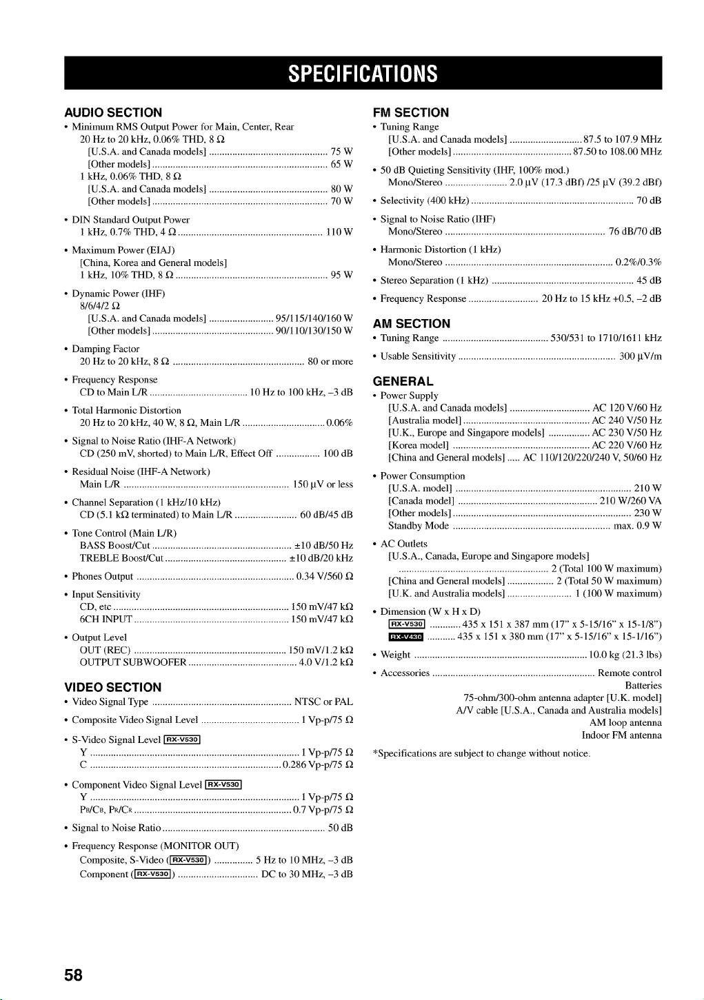
AUDIO SECTION
• Minimum RMS Output Power for Main, Center, Rear
20 Hz to 20 kHz, 0.06% THD, 8 f_
[U.S.A. and Canada models] .............................................. 75 W
[Other models] .................................................................... 65 W
1 kHz, 0.06% THD, 8
[U.S.A. and Canada models] .............................................. 80 W
[Other models] .................................................................... 70 W
• DIN Standard Output Power
1 kHz, 0.7% THD, 4 g2 ........................................................ ll0W
• Maximum Power (EIAJ)
[China, Korea and General models]
1 kHz, 10% THD, 8 g2 ........................................................... 95 W
• Dynamic Power (IHF)
8/6/4/2
[U.S.A. and Canada models] ......................... 95/115/140/160 W
[Other models] ............................................... 90/110/130/150 W
• Damping Factor
20 Hz to 20 kHz, 8 _ ................................................... 80 or more
• Frequency Response
CD to Main L/R ...................................... 10 Hz to 100 kHz, -3 dB
• Total Harmonic Distortion
20 Hz to 20 kHz, 40 W, 8 f2, Main L/R ................................ 0.06%
• Signal to Noise Ratio (IHF-A Network)
CD (250 mV, shorted) to Main L/R, Effect Off ................. 100 dB
• Residual Noise (IHF-A Network)
Main L/R ................................................................ 150 btV or less
• Channel Separation (1 kHz/10 kHz)
CD (5.1 k_2 terminated) to Main L/R ........................ 60 dB/45 dB
• Tone Control (Main L/R)
BASS Boost/Cut ...................................................... _+10 dB/50 Hz
TREBLE Boost/Cut ............................................... _+10dB/20 kHz
• Phones Output ............................................................. 0.34 V/560 f2
• Input Sensitivity
CD, etc .................................................................... 150 mV/47 k_2
6CH INPUT ............................................................ 150 mV/47 k_2
• Output Level
OUT (REC) ........................................................... 150 mV/1.2 k_2
OUTPUT SUBWOOFER .......................................... 4.0 V/1.2 k_2
VIDEO SECTION
• Video Signal Type ...................................................... NTSC or PAL
• Composite Video Signal Level ...................................... 1 Vp-p/75 _2
• S-Video Signal Level
Y ................................................................................. 1 Vp-p/75 f2
C .......................................................................... 0.286 Vp-p/75 f2
• Component Video Signal Level
Y ................................................................................. 1 Vp-p/75 f2
P_/CB, PR/CR ............................................................. 0.7 Vp-p/75 f2
• Signal to Noise Ratio ............................................................... 50 dB
• Frequency Response (MONITOR OUT)
Composite, S-Video (_) ............... 5 Hz to 10 MHz, -3 dB
Component (_) ............................... DC to 30 MHz, -3 dB
FM SECTION
• Tuning Range
[U.S.A. mad Canada models] ............................ 87.5 to 107.9 MHz
[Other models] .............................................. 87.50 to 108.00 MHz
• 50 dB Quieting Sensitivity (IHF, 100% rood.)
Mono/Stereo ........................ 2.0 btV (17.3 dBf)/25 btV (39.2 dBf)
• Selectivity (400 kHz) ............................................................... 70 dB
• Signal to Noise Ratio (IHF)
Mono/Stereo .............................................................. 76 dB/70 dB
• Harmonic Distortion (1 kHz)
Mono/Stereo ................................................................. 0.2%/0.3%
• Stereo Separation (1 kHz) ....................................................... 45 dB
• Frequency Response ........................... 20 Hz to 15 kHz +0.5, -2 dB
AM SECTION
• Tuning Rmlge ......................................... 530/531 to 1710/1611 kHz
• Usable Sensitivity ............................................................. 300 btV/m
GENERAL
• Power Supply
[U.S.A. mad Canada models] ............................... AC 120 V/60 Hz
[Australia model] ................................................. AC 240 V/50 Hz
[U.K., Europe mad Singapore models] ................ AC 230 V/50 Hz
[Korea model] ..................................................... AC 220 V/60 Hz
[China mad General models] ..... AC 110/120/220/240 V, 50/60 Hz
• Power Consumption
[U.S.A. model] .................................................................... 210 W
[Canada model] ...................................................... 210 W/260 VA
[Other models] ..................................................................... 230 W
Standby Mode ............................................................. max. 0.9 W
• AC Outlets
[U.S.A., Canada, Europe and Singapore models]
.......................................................... 2 (Total 100 W maximum
[China mad General models] .................. 2 (Total 50 W maximum
[U.K. mad Australia models] ......................... 1 (100 W maximum
• Dimension (W x H x D)
............ 435 x 151 x 387 mm (17" x 5-15/16" x 15-1/8")
........... 435 x 151 x 380 mm (17" x 5-15/16" x 15-1/16")
• Weight ................................................................... 10.0 kg (21.3 lbs)
• Accessories ............................................................... Remote control
Batteries
75-ohm/300-ohm antenna adapter [U.K. model]
A/V cable [U.S.A., Canada mad Australia models]
AM loop antenna
Indoor FM antenna
*Specifications are subject to change without notice.
58
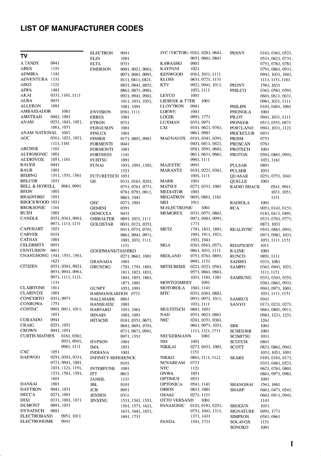
LIST OF MANUFACTURER CODES
ELECTRON 0941
T_ EL1N 100 l
ATANDY 094 t ELTA 0331
ABEX 1151 EMERSON 0001, 0021, 006t,
ADM1RA 1141 0071,008t, 009t,
ADVENTURA 1131 0t 11,0811,082t,
A1KO 1121 0831,084 t, 085 t,
A1WA 148t 0861, 087t, 0901,
AKA1 0331, t 101, 1t 1t 0921, 094t, 098t,
ALBA 043t 1011, t031, 105t,
ALLERON t09t 1081, 109t
AMBASSADOR 1081 ENVISION 0361, 1tlt
AMSTRAD 0481, 1081 ERRES 1001
ANAM 0251, 1041, 1051, ETRON 0331
t06t, 1071 FERGUSON 1001
ANAM NATIONAL 104t FINLUX 1001
AOC 0361, t021, 1031, FISHER 0t71, 080t, 098t
111 t, t 16t FORMENT1 0441
ARCHER 1161 FORMONT1 1001
AUD1OSONIC 1001 FORTRESS 1 t41
AUD1OVOX 1051, t 161 FUJITSU 1091
BAUER 0441 FUNA1 105t, 109t, 150t,
BAUR 100t 1521
BEIJING 15tl, 155t, 1561 FUTURETECH 1051
BELCOR 103t GE 0t3t, 0t61, 020t,
BELL & HOWELL 098t, 0991 0751, 0761, 0771,
BEON 1001 0781, 0791, 081t,
BRADFORD 105t 0861, 104t
BROCKWOOD 103t GEC 0271, 100t
BROKSONIC 1161 GEMINI 0391
BUSH 1001 GENEXXA 0431
CANDLE 0351, 0361, 0961, GIBRALTER 0891, t031,1tlt
0971, tlt1,1t3t GOLDSTAR 003t, 0t2t, 035t,
CAPEHART 102t 0411,0731,074t,
CARVER 0101 0861, 094t, 0971,
CATHAY 1001 1001, t031, t t 1t,
CELEBRITY 095 t 1 t51
CENTURION 0411 GOODMANS/TASHIKO
CHANGHONG 154t, 1551, 1561, 0271, 0661, 100t
1621 GRANADA 1001
CITIZEN 0351, 0361, 0921, GRUND1G 178t, 179t, 1801,
093t, 0941, 0961, 1811, t821, 183t,
0971, tltl, 1t2t, 1841, 1851, 1861,
1131 1871, 188t
CLAIRTONE 1011 GUNPY 1051, 1091
CLAR1VOX 1001 HARMAN/KARDON 0721
CONCERTO 0351,0971 HALLMARK 0861
CONROWA 1751 HANSEATIC 1001
CONTEC 0901, 09t 1, t0t 1, HARVARD 105t, 106t
105t HINAR1 1001, 109t
CORANDO 0941 HITACHI 0t81, 0351, 0671,
CRAIG 0251,1051 0681,069t, 070t,
CROWN 094 t, 1051 0711,0871,094 t,
CURTIS MATHES 0161, 0361, 0971, 135t
093t, 0941, HYPSON 1001
0981, 1ttl IMA 1051
CXC 105 t INDIAN A 1001
DAEWOO 029t, 0301, 0331, INFINITY REFERENCE
072t, 0941, 1001, 0t01
1031, 1121, t191, INTERFUNK 1001
1531, 1581, 1591, ITT 06tt
160t JANE1L 1 t3t
DANSAI 100t JBL 0t01
DAYTRON 094t, 1031 JCB 0951
DECCA 027 t, 1001 JENSEN 03 t 1
D1X1 033t, 1001, 1071 JINXING 1531, 154t, 155t,
DUMONT 0891, 1031 1561, 157t, 162t,
DYNATECH 088t 1631, 1641, 165t,
ELECTROBAND 0951, t0tl 1691, 173t
ELECTROHOME 094 t
JVC (VICTOR) 0261, 028t, 064t,
0651, 0661, 084t
KAWASHO 0901
KAYPANI 1021
KENWOOD 0361, t031, ttll
KLOSS 0631, 0721, 1t3t
KTV 092t, 0941, 101t,
105t, tllt
LEYCO 1001
LIESENK & TTER 100t
LLOYTRON 0941
LOEWE 1001
LOGIK 0991, 1771
LUXMAN 0351,097 t
LXI 0t01, 0621, 0761,
0861,098 t
MAGNAVOX 0t01,034t,0391,
0401, 0411,042t,
0581,059t, 060t,
0611, 0631, 0661,
096t, tllt
MAJESTIC 0991
MARANTZ 0t01, 022t, 0361,
100t, t11t
MARK 1001
MATSU1 0271, 033t, 100t
MEDIATOR 1001
MEGATRON 069t, 0861, 1t61
MEI 10t t
M-ELECTRONIC t00t
MEMOREX 033t, 0571, 086t,
0971,098 t, 099 t,
1771
METZ 1791 183t, 189t,
1901 t9tl, 192t,
1931 194t
MGA 0361 0561, 057t,
0861 t031, 1tlt
MIDLAND 0751 0761, 089t,
094t 1t5t
MITSUBISHI 0221 032t,0561,
0571 0661, 0861,
1031 t101,138t
MONTGOMERY 109t
MOTOROLA 104t, 1 t4t
MTC 0351, 0361, 088 t,
0931, 0971, 101t,
1031, tllt
MULTITECH 0881, 105t
NAD 0551,062t, 0861
NEC 0241, 035t, 0361,
0661, 0971, 103t,
1tlt, t321, t7tl
NECKERMANN 100t
NEI 1001
NIKKAI 0271, 043t, 100t,
1t5t
NIKKO 086t, 11tl, t121
NOVABEAM 0721
NTC 1t2t
ONWA 1051
OPTIMUS 0551
OPTON1CA 0541, 1t4t
ORION 0831, 100t
OSAK1 027t, 1t5t
OTTO VERSAND 100t
PANASON1C 010t,0t9t,025t,
0751, t041, 131t,
1371, 143t
PANDA 1541, 172t
PENNY 0161, 0361, 0521,
0531, 0621, 0731,
075t, 0761, 0781,
079t, 0861, 0931,
094t, 1031, 1041,
11tl, 1t5t, 1t61
PEONY 1561, 1621
PHILCO 0361, 0581, 0591,
060 t, 0611,0631,
096t, 1031, 11tl
PHIL1PS 010t, 0401, 1001
PHONOLA 100t
PILOT 0941, 103t, 11 t 1
PIONEER 051 t, 0551, 0871
PORTLAND 0941, 103t, 1121
PRICECLUB 0931
PRISM 075 t
PROSCAN 076t
PROTECH 1001
PROTON 050t, 0861, 0941,
1021, t 161
PULSAR 089t
PULSER 1031
QUASAR 0251, 0751, 1041
QUELLE 100t
RADIO SHACK 0541, 094t,
1031, 105t,
1t5t
RADIOLA 1001
RCA 0051, 0141, 0151,
018t, 041 t, 0491,
053t, 0761, 0771,
0871, 1031
REALISTIC 0541, 0861, 0941,
0971, 0981, 1031,
1051, 1tlt, 1t5t
RHAPSODY 1011
R-LINE 100t
RUNCO 0891, t 1t 1
SAISHO 0331,1081
SAMPO 036t, 0941, 1021,
1111, t15t
SAMSUNG 0331, 0341, 0351,
036t, 0861, 0931,
094t, 0971, 1001,
1031, 1tlt, 1t5t
SAMSUX 0941
SANYO 0171,0231,0271,
0661, 0801, 09t 1,
098t, 1231, 1251,
126t
SBR 1001
SCHEIDER 100t
SCIMITSU 103 t
SCOTCH 086 t
SCOTT 0831,0861,0941,
1031, 1051, 1091
SEARS 0101, 0161, 0171,
035t, 0481, 0521,
062t, 0761, 0801,
086t, 0971, 0981,
109t
SHANGHAI 156t, 1681
SHARP 046 t, 0471,0541,
066t, 09t 1, 0941,
114t
SHOGUN 103 t
SIGNATURE 0991, t771
SIMPSON 058t, 0961
SOLAVOX 1151
SONOKO 100t
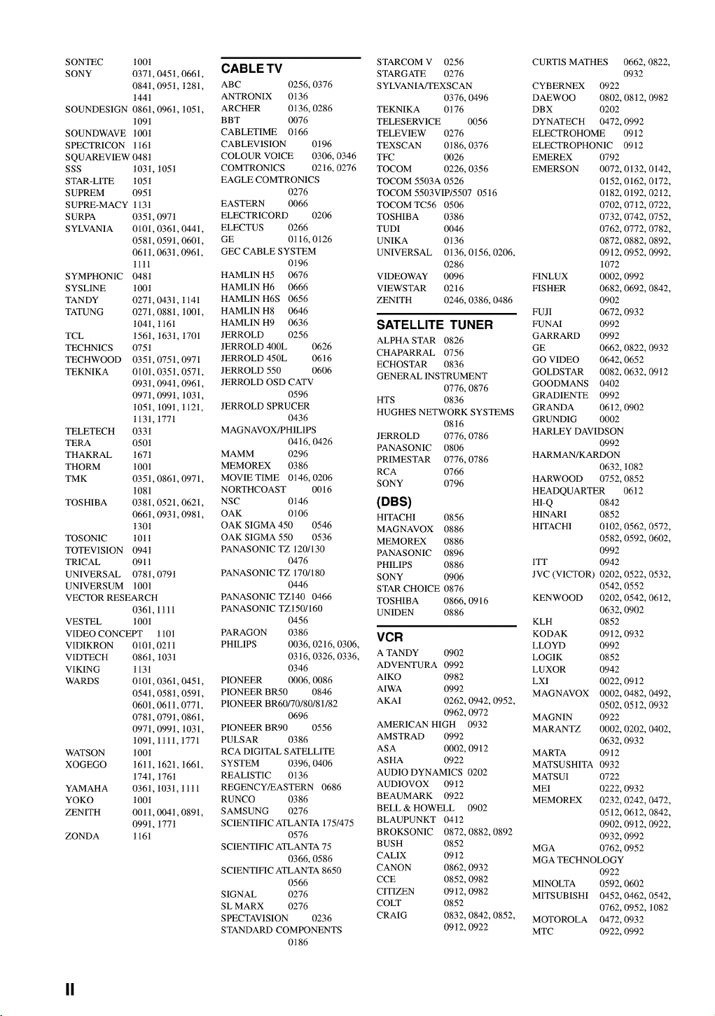
SONTEC100t
SONY 0371,0451,0661,
084t,095t,1281,
t44t
SOUNDES1GN0861,096t,1051,
1091
SOUNDWAVE100t
SPECTRICONt161
SQUAREVIEW048t
SSS 1031,105t
STAR-LITE105t
SUPREM0951
SUPRE-MACY113t
SURPA 0351,097t
SYLVANIA0101,0361,0441,
058t,0591,0601,
061t,063t,0961,
11tl
SYMPHONIC048t
SYSL1NE100t
TANDY 027t,0431,t141
TATUNG0271,0881,1001,
104t,1161
TCL 1561,163t,1701
TECHNICS075t
TECHWOOD035t,0751,0971
TEKNIKA0101,035t,0571,
093t,094t,0961,
097t,099t,t031,
1051,109t,t121,
1131,1771
TELETECH033t
TERA 050t
THAKRAL167t
THORM 100t
TMK 0351,086t,0971,
1081
TOSHIBA0381,0521,0621,
0661,093t,0981,
130t
TOSON1C101t
TOTEV1S1ON094t
TR1CAL 0911
UNIVERSAL078t,079t
UNIVERSUM1001
VECTORRESEARCH
0361,1tll
VESTEL t00t
VIDEOCONCEt_110t
VIDIKRON010t,02t1
VIDTECH0861,103t
VIKING 1131
WARDS 0101,0361,0451,
054t,058t,0591,
0601,061t,0771,
078t,079t,0861,
097t,099t,t031,
109t,1tlt,t771
WATSON1001
XOGEGO161t,1621,t661,
174t,1761
YAMAHA036t,103t,tltl
YOKO 100t
ZENITH 0011,004t,0891,
099t,t771
ZONDA 1161
CAB LE TV
ABC 0256, 0376
ANTRONIX 0t36
ARCHER 0t 36, 0286
BBT 0076
CABLETIME 0t66
CABLEV1SION 0t96
COLOUR VOICE 0306, 0346
COMTRON1CS 02t6, 0276
EAGLE COMTRON1CS
0276
EASTERN 0066
ELECTRICORD 0206 TOSHIBA
ELECTUS 0266 TUDI
GE 0t 16, 0126 UNIKA
GEC CABLE SYSTEM UNIVERSAL
0t96
HAML1N H5 0676 V1DEOWAY
HAML1N H6 0666 VIEWSTAR
HAML1N H6S 0656 ZENITH
HAML1N H8 0646
HAML1N H9 0636
JERROLD 0256
JERROLD 400L 0626
J ERROLD 450L 06 t 6
JERROLD 550 0606
JERROLD OSD CATV
0596
JERROLD SPRUCER
0436
MAGNAVOX/PH1L1PS
JERROLD 0776, 0786
04t6, 0426 PANASONIC 0806
MAMM 0296
PRIMESTAR 0776, 0786
MEMOREX 0386 RCA 0766
MOVIE TIME 0t46, 0206 SONY 0796
NORTHCOAST 0016
NSC 0t46 (DBS)
OAK 0t06 HITACHI 0856
OAK SIGMA450 0546 MAGNAVOX 0886
OAKSIGMA550 0536 MEMOREX 0886
PANASON1C TZ 120/130 PANASONIC 0896
0476 PH1LIPS 0886
PANASON1C TZ 170/180 SONY 0906
0446 STAR CHOICE 0876
PANASON1C TZt40 0466 TOSHIBA 0866, 0916
PANASON1C TZt50/160 UN1DEN 0886
0456
PARAGON 0386
PHIL1PS 0036, 0216, 0306,
03t6, 0326, 0336,
0346
PIONEER 0006, 0086
PIONEER BR50 0846
PIONEER BR60/70/80/8 t/82
0696
PIONEER BR90 0556
PULSAR 0386
RCA DIGITAL SATELLITE
SYSTEM 0396, 0406
REALISTIC 0136
REGENCY/EASTERN 0686
RUNCO 0386
SAMSUNG 0276
SCIENTIFIC ATLANTA 175/475
0576 BROKSON1C
SCIENTIFIC ATLANTA 75 BUSH
0366, 0586 CAL1X
SCIENTIFIC ATLANTA 8650 CANON
0566 CCE
SIGNAL 0276 CITIZEN
SL MARX 0276 COLT
SPECTAV1S1ON 0236 CRAIG
STANDARD COMPONENTS
0t86
STARCOM V 0256
STARGATE 0276
S YLVAN IA/TEXSCAN
0376, 0496
TEKNIKA 0t76
TELESERV1CE 0056
TELEV1EW 0276
TEXSCAN 0t86, 0376
TFC 0026
TOCOM 0226, 0356
TOCOM 5503A 0526
TOCOM 5503VIP/5507 05t6
TOCOM TC56 0506
0386
0046
0t36
0t36,0t56,0206,
0286
0096
0216
0246, 0386,0486
CURTIS MATHES 0662, 0822,
0932
CYBERNEX 0922
DAEWOO 0802, 08 t 2, 0982
DBX 0202
DYNATECH 0472, 0992
ELECTROHOME 0912
ELECTROPHON1C 0912
EMEREX
EMERSON
FINLUX
FISHER
FUJI
SATELLITE TUNER FUNAI
ALPHA STAR 0826 GARRARD
CHAPARRAL 0756 GE
ECHOSTAR 0836 GO VIDEO
GENERAL INSTRUMENT GOLDSTAR
0776, 0876 GOODMANS
HTS 0836 GRAD1ENTE
HUGHES NETWORK SYSTEMS GRANDA
0816 GRUND1G
VCR
A TANDY 0902
ADVENTURA 0992
AIKO 0982
AIWA 0992
AKA1 0262, 0942, 0952,
0962, 0972
AMERICAN HIGH 0932
AMSTRAD 0992
ASA 0002, 0912
ASHA 0922
AUDIO DYNAMICS 0202
AUD1OVOX 09 t 2
BEAUMARK 0922
BELL & HOWELL 0902
BLAUPUNKT 0412
0872,0882,0892
0852
0912
0862,0932
0852,0982
0912,0982
0852
0832,0842,0852,
09t2,0922
0792
0072,0132,0142,
0152,0162,0172,
0182,0192,02t2,
0702, 0712, 0722,
0732, 0742, 0752,
0762, 0772, 0782,
0872,0882,0892,
0912,0952,0992,
1072
0002,0992
0682,0692,0842,
0902
0672,0932
0992
0992
0662, 0822,0932
0642,0652
0082, 0632,09t2
0402
0992
0612,0902
0002
HARLEY DAVIDSON
0992
HARMAN/KARDON
0632, 1082
HARWOOD 0752, 0852
HEADQUARTER 0612
H1-Q 0842
H1NARI 0852
HITACHI 0102, 0562, 0572,
0582, 0592, 0602,
0992
1TT 0942
JVC (VICTOR) 0202, 0522, 0532,
0542, 0552
KENWOOD 0202, 0542, 0612,
0632, 0902
KLH 0852
KODAK 09t2, 0932
LLOYD 0992
LOG1K 0852
LUXOR 0942
LX1 0022, 09t2
MAGNAVOX 0002, 0482, 0492,
0502, 05t2, 0932
MAGNIN 0922
MARANTZ 0002, 0202, 0402,
0632, 0932
MARTA 0912
MATSUSHITA 0932
MATSU1 0722
ME1 0222, 0932
MEMOREX 0232, 0242, 0472,
0512, 06t2, 0842,
0902, 09t2, 0922,
0932, 0992
MGA 0762, 0952
MGA TECHNOLOGY
0922
M1NOLTA 0592, 0602
M1TSUBISHI 0452,0462,0542,
0762, 0952, 1082
MOTOROLA 0472, 0932
MTC 0922, 0992
II
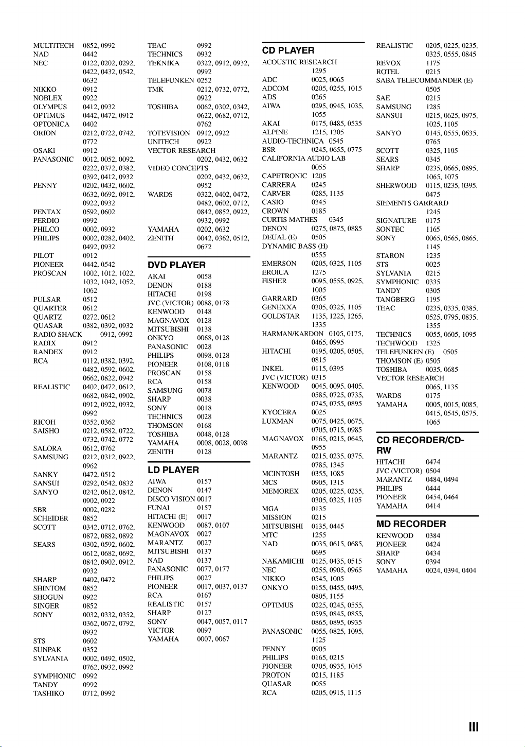
MULT1TECH 0852, 0992
NAD 0442
NEC 0122, 0202, 0292,
0422, 0432, 0542,
0632
NIKKO 09t2
NOBLEX 0922
OLYMPUS 04t2, 0932
OPTIMUS 0442, 0472, 09t2
OPTONICA 0402
ORION 02t2, 0722, 0742,
0772
OSAKI 0912
PANASONIC 0012,0052,0092,
0222, 0372, 0382,
0392, 04t2, 0932
PENNY 0202, 0432, 0602,
0632, 0692, 09t2,
0922, 0932
PENTAX 0592, 0602
PERDIO 0992
PHILCO 0002, 0932
PHIL1PS 0002, 0282, 0402,
0492, 0932
PILOT 09 t 2
PIONEER 0442, 0542
PROSCAN 1002, 10t2, t022,
1032, 1042, 1052,
1062
PULSAR 05t2
QUARTER 0612
QUARTZ 0272, 0612
QUASAR 0382, 0392, 0932
RADIO SHACK 09t2, 0992
RADIX 09t2
RANDEX 09t2
RCA 01 t2, 0382, 0392,
0482, 0592, 0602,
0662, 0822, 0942
REALISTIC 0402, 0472, 06t2,
0682, 0842, 0902,
09t2, 0922, 0932,
0992
RICOH 0352, 0362
SAISHO 02t2, 0582, 0722,
0732, 0742, 0772
SALORA 0612, 0762
SAMSUNG 02t2, 03t2, 0922,
0962
SANKY 0472, 05t2
SANSUI 0292, 0542, 0832
SANYO 0242, 06t2, 0842,
0902, 0922
SBR 0002, 0282
SCHEIDER 0852
SCOTT 0342, 0712, 0762,
0872, 0882, 0892
SEARS 0302, 0592, 0602,
0612, 0682, 0692,
0842, 0902, 09t2,
0932
SHARP 0402, 0472
SHINTOM 0852
SHOGUN 0922
SINGER 0852
SONY 0032, 0332, 0352,
0362, 0672, 0792,
0932
STS 0602
SUNPAK 0352
SYLVANIA 0002, 0492, 0502,
0762, 0932, 0992
SYMPHONIC 0992
TANDY 0992
TASH1KO 0712, 0992
TEAC 0992
TECHNICS 0932
TEKNIKA 0322, 0912, 0932,
0992
TELEFUNKEN 0252
TMK 0212, 0732, 0772,
0922
TOSHIBA 0062, 0302, 0342,
0622, 0682, 0712,
0762
TOTEV1S1ON 0912, 0922
UNITECH 0922
VECTOR RESEARCH
0202, 0432, 0632
VIDEO CONCEPTS
0202, 0432, 0632,
0952
WARDS 0322, 0402, 0472,
0482, 0602, 0712,
0842, 0852, 0922,
0932, 0992
YAMAHA 0202, 0632
ZENITH 0042, 0362, 0512,
0672
DVD PLAYER
AKAI 0058
DENON 0t88
HITACHI 0t98
JVC (VICTOR) 0088, 0t78
KENWOOD 0t48
MAGNAVOX 0t28
MITSUBISHI 0t38
ONKYO 0068, 0 t 28
PANASON1C 0028
PH1LIPS 0098, 0 t 28
PIONEER 0t08, 0t 18
PROSCAN 0t58
RCA 0t58
SAMSUNG 0078
SHARP 0038
SONY 0018
TECHNICS 0028
THOMSON 0t68
TOSHIBA 0048, 0t28
YAMAHA 0008, 0028, 0098
ZENITH 0t28
LD PLAYER
AIWA 0t57
DENON 0t47
DISCO VISION 0017
FUNA1 0t57
HITACHI (E) 0017
KENWOOD 0087, 0t07
MAGNAVOX 0027
MARANTZ 0027
MITSUBISHI 0t37
NAD 0t37
PANASON1C 0077, 0t77
PH1LIPS 0027
PIONEER 0017, 0037, 0t37
RCA 0 t 67
REALISTIC 0t57
S HARP 0 t 27
SONY 0047, 0057, 0t 17
VICTOR 0097
YAMAHA 0007, 0067
CD PLAYER
ACOUSTIC RESEARCH
1295
ADC 0025,0065
ADCOM 0205,0255,1015
ADS 0265
AIWA 0295, 0945, 1035,
1055
AKAI 0t75,0485, 0535
ALPINE 1215, 1305
AUDIO-TECHNICA 0545
BSR 0245, 0655, 0775
CALIFORNIA AUDIO LAB
0055
CAPETRONIC 1205
CARRERA 0245
CARVER 0285, 1t35
CASIO 0345
CROWN 0185
CURTIS MATHES 0345
DENON 0275, 0875, 0885
DEUAL (E) 0505
DYNAMIC BASS (H)
0555
EMERSON 0205, 0325, 1 t05
ERO1CA 1275
FISHER 0095, 0555, 0925,
1005
GARRARD 0365
GENEXXA 0305, 0325, 1t05
GOLDSTAR 1t35,1225, t265,
1335
HARMAN/KARDON 0105,0175,
0465,0995
HITACHI 0t95,0205,0505,
0815
INKEL 0t 15, 0395
JVC (VICTOR) 0315
KENWOOD 0045, 0095, 0405,
0585,0725,0735,
0745,0755,0895
KYOCERA 0025
LUXMAN 0075,0425,0675,
0705,0715,0985
MAGNAVOX 0t65,0215,0645,
0955
MARANTZ 0215,0235,0375,
0785,1345
MC1NTOSH 0355,1085
MCS 0905,1315
MEMOREX 0205, 0225, 0235,
0305,0325,1t05
MGA 0t35
MISSION 0215
MITSUBISHI 0t35,0445
MTC 1255
NAD 0035, 0615, 0685,
0695
NAKAMICH1 0t25,0435,0515
NEC 0255,0905,0965
NIKKO 0545, 1005
ONKYO 0t55,0455,0495,
0805,1t55
OPTIMUS 0225,0245,0555,
0595,0845,0855,
0865,0895,0935
PANASON1C 0055,0825,1095,
1t25
PENNY 0905
PH1LIPS 0 t 65, 0215
PIONEER 0305, 0935, 1045
PROTON 0215, 1t85
QUASAR 0055
RCA 0205,0915,1t15
REALISTIC 0205,0225, 0235,
0325,0555,0845
REVOX 1175
ROTEL 0215
SABA TELECOMMANDER (E)
0505
SAE 02t5
SAMSUNG 1285
SANSUI 02t5,0625,0975,
1025, t105
SANYO 0145, 0555, 0635,
0765
SCOTT 0325, t105
SEARS 0345
SHARP 0235,0665,0895,
1065,1075
SHERWOOD 01t5,0235,0395,
0475
SIEMENTS GARRARD
1245
SIGNATURE 0175
SONTEC 1165
SONY 0065,
1145
STARON 1235
STS 0025
SYLVANIA 0215
0565,0865,
SYMPHONIC 0335
TANDY 0305
TANGBERG 1195
TEAC 0235, 0335, 0385,
0525, 0795, 0835,
1355
TECHNICS 0055, 0605, 1095
TECHWOOD t 325
TELEFUNKEN (E) 0505
THOMSON (E) 0505
TOSHIBA 0035, 0685
VECTOR RESEARCH
0065, t 135
WARDS 0175
YAMAHA 0005, 00t5, 0085,
04t5, 0545, 0575,
1065
CD RECORDER/CD-
RW
HITACHI 0474
JVC (VICTOR) 0504
MARANTZ 0484, 0494
PHIL1PS 0444
PIONEER 0454, 0464
YAMAHA 04 t 4
MD RECORDER
KENWOOD 0384
PIONEER 0424
SHARP 0434
SONY 0394
YAMAHA 0024, 0394, 0404
III
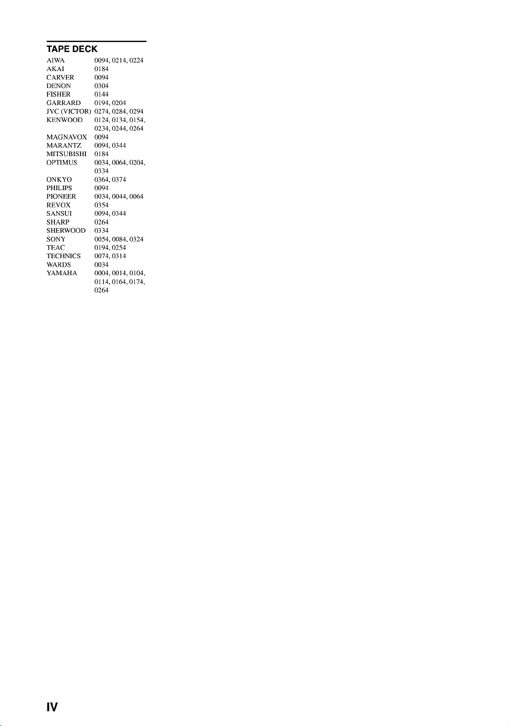
TAPE DECK
AIWA
AKA1
CARVER
DENON
FISHER
GARRARD
JVC (VICTOR)
KENWOOD
MAGNAVOX
MARANTZ
MITSUB1SH1
OPTIMUS
ONKYO
PH1LIPS
PIONEER
REVOX
SANSUI
SHARP
SHERWOOD
SONY
TEAC
TECHNICS
WARDS
YAMAHA
0094,02t4,0224
0184
0094
0304
0144
0194,0204
0274,0284,0294
0124, 0134, 0154,
0234,0244,0264
0094
0094,0344
0184
0034, 0064, 0204,
0334
0364,0374
0094
0034, 0044, 0064
0354
0094,0344
0264
0334
0054,0084,0324
0194,0254
0074,03t4
0034
0004, 00t4, 0104,
0114,0t64,0174,
0264
IV

OYAMAHA
YAMAHA ELECTRONICS CORPORATION, USA 6660 ORANGETHORPE AVE., BUENA PARK, CALIE 90620, U,S,A,
YAMAHA CANADA MUSIC LTD. 135 MILNER AVE,, SCARBOROUGH, ONTARIO M1S 3R1, CANADA
YAMAHA ELECTRONIK EUROPA G.m.b.H. SIEMENSSTR. 22-34, 25462 RELUNGEN BE1 HAMBURG, F.R, OF GERMANY
YAMAHA ELECTRONIQUE FRANCE S.A. RUE AMBROISE CROIZAT BP70 CROISSY-BEAUBOURG 77312 MARNE-LA-VALLEE CEDEX02, FRANCE
YAMAHA ELECTRONICS (UK) LTD. YAMAHA HOUSE, 200 RICKMANSWORTH ROAD WATFORD, HERTS WD1 7JS, ENGLAND
YAMAHA SCANDINAVIA A.B. J A WETTERGRENS GATA 1, BOX 30053, 400 43 VASTRA FROLUNDA, SWEDEN
YAMAHA MUSIC AUSTRALIA PTY, LTD. 17-33 MARKET S_, SOUTH MELBOURNE, 3205 VIC,, AUSTRAUA
YAMAHA CORPORATION
Printed in Malaysia I_lvl[_o V874570