

Operator's Manual
MRN°
ZTS 70
Zero-Turn Rear Engine Rider with Electric Start
Model No.
107.280070 (26HP Briggs & Stratton Engine with 52" Mower)
CAUTION: Before using this product, read
the manual and follow all its Safety Rules
and Operating Instructions.
For answers to your questions about this
product, call:
1=800=659=5917
Sears Craftsman Help Line
5 am - 5 pm, Mon- Sat
Sears Brands Management Corporation, Hoffman Estates, IL 60179 U.S.A.
Visit our Craftsman website: www.craftsman.com
7! 04938
Revision A

Thankyou forpurchasingthisquality-builtCRAFTSMANmower.We'repleasedthatyou'veplacedyourconfidence
intheCRAFTSMANbrand.Whenoperatedandmaintainedaccordingtotheinstructionsinthismanual,your
CRAFTSMANproductwillprovidemanyyearsofdependableservice.
Thismanualcontainssafetyinformationto makeyouawareofthehazardsandrisksassociatedwithmowersand
howtoavoidthem.Thisproductanditsapprovedattachments/accessoriesaredesignedandintendedonlyforlawn
workorsnowremovalandarenotintendedforanyotherpurpose.Itisimportantthatyoureadandunderstandthese
instructionsthoroughlybeforeattemptingto startoroperatethisequipment.Savetheseoriginalinstructions for
future reference.
Where to Find Us
You never have to look far to find support and service for your CRAFTSMAN mower. There are authorized service
dealers in North America who provide quality service. You can contact Customer Service by phone at (800) 659-5917,
or locate a dealer on the Internet at www.craftsman.com.
Mower
Model Number
Serial Number
Engine
Model Type Trim
Date Code
Date Purchased
2

Operator Safety .................................................. 4
Features and Controls ..................................... 13
Control Functions .................................................. 13
Operation .......................................................... 15
General Operating Safety ...................................... 15
Checks Before Starting ......................................... 15
Starting the Engine ................................................ 16
Stopping the Rider and Engine ............................. 16
Mowing .................................................................. 16
Pushing the Rider by Hand ................................... 16
Zero Turn Driving Practice .................................... 17
Attaching a Trailer ................................................. 19
Maintenance ..................................................... 20
Maintenance Chart ................................................ 20
Checking Tire Pressures ....................................... 21
Checking/Adding Fuel ........................................... 21
Fuel Filter .............................................................. 21
Engine Maintenance ............................................. 21
Washing the Mower Deck ..................................... 22
Storage .................................................................. 22
Adjustments and Service ................................ 23
Seat Adjustments .................................................. 23
Ground Speed Lever Adjustment .......................... 23
Speed Balancing Adjustment ................................ 23
Cutting Height Adjustment .................................... 24
Mower Removal and Installation ........................... 24
PTO Clutch Adjustment ......................................... 26
Check Mower Blade Stoppping Time .................... 26
Mower Deck Leveling ............................................ 27
Servicing the Mower Blades .................................. 28
Lubrication ............................................................ 29
Cleaning the Battery and Cables ........................... 30
Battery Charging ................................................... 30
Troubleshooting ............................................... 31
Troubleshooting the Rider ..................................... 31
Troubleshooting the Mower ................................... 32
Specifications ................................................... 33
Warranty ............................................................ 34
Repair Protection Agreement ......................... 35
3

Operating Safety
Congratulations on purchasing a superior-quality piece of lawn
and garden equipment. Our products are designed and manufac-
tured to meet or exceed all industry standards for safety.
Do not operate this machine unless you have familiarized yourself
with it. Reading and understanding this operator's manual is a
way to do just that.
Power equipment is only as safe as the operator. If it is misused,
or not properly maintained, it can be dangerous! Remember, you
are responsible for your safety and that of those around you.
Use common sense, and think through what you are doing. If you
are not sure that the task you are about to perform can be safely
done with the equipment you have chosen, ask a professional:
contact your local authorized dealer.
Read the Manual
The operator's manual contains important safety infor-
mation you need to be aware of BEFORE you operate
your unit as well as DURING operation.
Safe operating techniques, an explanation of the prod-
uct's features and controls, and maintenance informa-
tion is included to help you get the most out of your
equipment investment.
Be sure to completely read the Safety Rules and
Information found on the following pages. Also com-
pletely read the Operation section.
Children
Tragic accidents can occur with children. Do
not allow them anywhere near the area of
operation. Children are often attracted to the
unit and mowing activity. Never assume that
children will remain where you last saw them.
If there is a risk that children may enter the
area where you are mowing, have another
responsible adult watch them.
4
3.5
2O
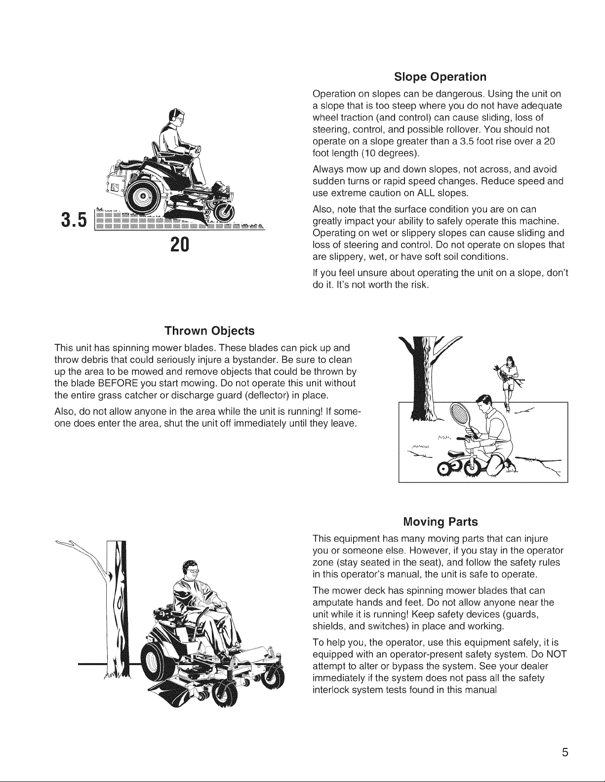
Slope Operation
Operation on slopes can be dangerous. Using the unit on
a slope that is too steep where you do not have adequate
wheel traction (and control) can cause sliding, loss of
steering, control, and possible rollover. You should not
operate on a slope greater than a 3.5 foot rise over a 20
foot length (10 degrees).
Always mow up and down slopes, not across, and avoid
sudden turns or rapid speed changes. Reduce speed and
use extreme caution on ALL slopes.
Also, note that the surface condition you are on can
greatly impact your ability to safely operate this machine.
Operating on wet or slippery slopes can cause sliding and
loss of steering and control. Do not operate on slopes that
are slippery, wet, or have soft soil conditions.
If you feel unsure about operating the unit on a slope, don't
do it. It's not worth the risk.
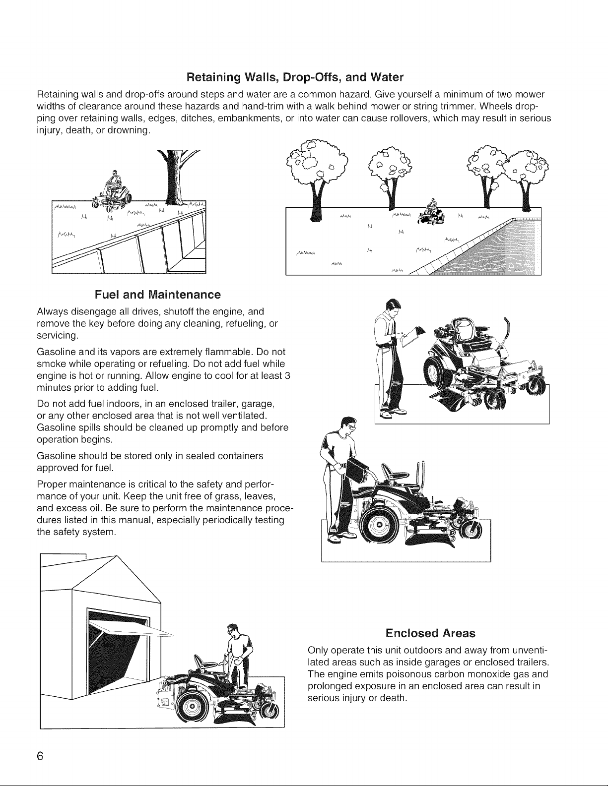
Thrown Objects
This unit has spinning mower blades. These blades can pick up and
throw debris that could seriously injure a bystander. Be sure to clean
up the area to be mowed and remove objects that could be thrown by
the blade BEFORE you start mowing. Do not operate this unit without
the entire grass catcher or discharge guard (deflector) in place.
Also, do not allow anyone in the area while the unit is running! If some-
one does enter the area, shut the unit off immediately until they leave.
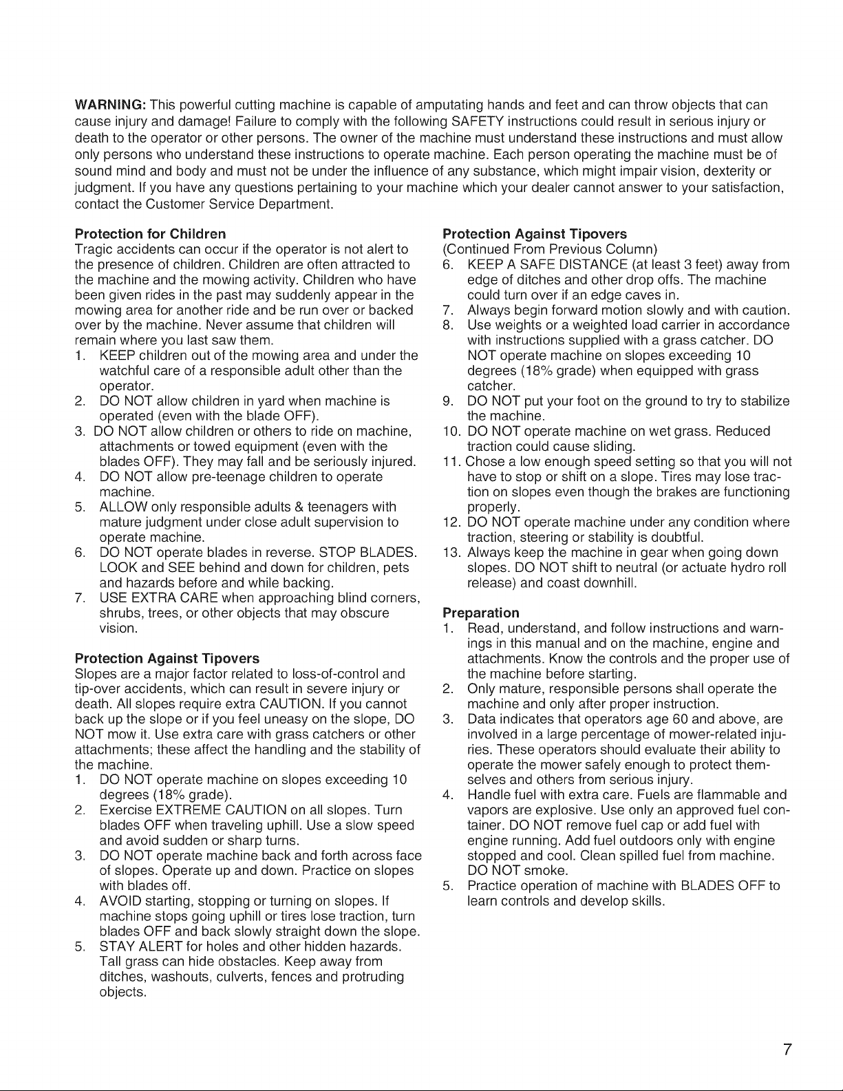
Moving Parts
This equipment has many moving parts that can injure
you or someone else. However, if you stay in the operator
zone (stay seated in the seat), and follow the safety rules
in this operator's manual, the unit is safe to operate.
The mower deck has spinning mower blades that can
amputate hands and feet. Do not allow anyone near the
unit while it is running! Keep safety devices (guards,
shields, and switches) in place and working.
To help you, the operator, use this equipment safely, it is
equipped with an operator-present safety system. Do NOT
attempt to alter or bypass the system. See your dealer
immediately if the system does not pass all the safety
interlock system tests found in this manual
5
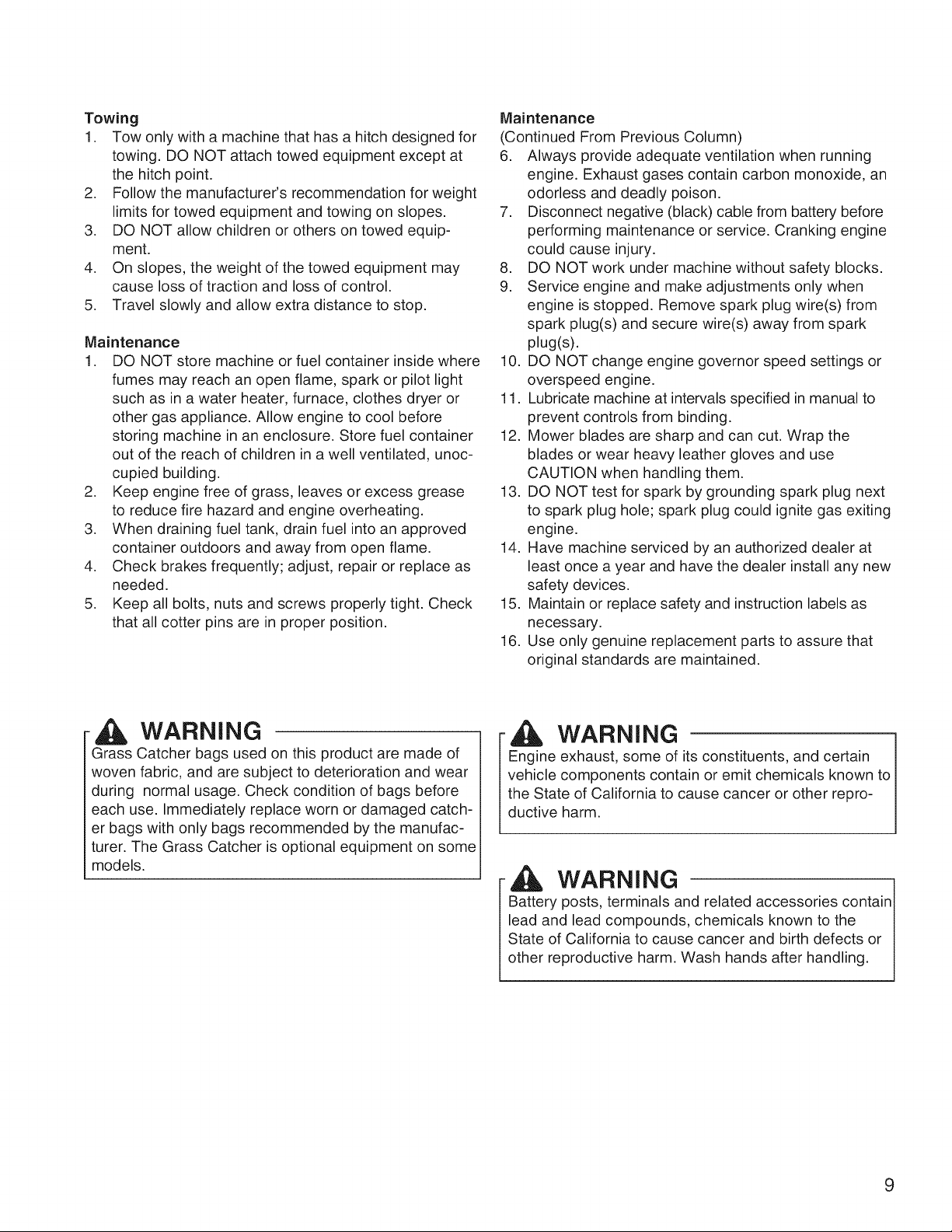
Retaining Walls, Drop-Offs, and Water
Retaining walls and drop-offs around steps and water are a common hazard. Give yourself a minimum of two mower
widths of clearance around these hazards and hand-trim with a walk behind mower or string trimmer. Wheels drop-
ping over retaining walls, edges, ditches, embankments, or into water can cause rollovers, which may result in serious
injury, death, or drowning.
Fuel and Maintenance
Always disengage all drives, shutoff the engine, and
remove the key before doing any cleaning, refueling, or
servicing.
Gasoline and its vapors are extremely flammable. Do not
smoke while operating or refueling. Do not add fuel while
engine is hot or running. Allow engine to cool for at least 3
minutes prior to adding fuel.
Do not add fuel indoors, in an enclosed trailer, garage,
or any other enclosed area that is not well ventilated.
Gasoline spills should be cleaned up promptly and before
operation begins.
Gasoline should be stored only in sealed containers
approved for fuel.
Proper maintenance is critical to the safety and perfor-
mance of your unit. Keep the unit free of grass, leaves,
and excess oil. Be sure to perform the maintenance proce-
dures listed in this manual, especially periodically testing
the safety system.
Enclosed Areas
Only operate this unit outdoors and away from unventi-
lated areas such as inside garages or enclosed trailers.
The engine emits poisonous carbon monoxide gas and
prolonged exposure in an enclosed area can result in
serious injury or death.
6
WARNING: This powerful cutting machine is capable of amputating hands and feet and can throw objects that can
cause injury and damage! Failure to comply with the following SAFETY instructions could result in serious injury or
death to the operator or other persons. The owner of the machine must understand these instructions and must allow
only persons who understand these instructions to operate machine. Each person operating the machine must be of
sound mind and body and must not be under the influence of any substance, which might impair vision, dexterity or
judgment. If you have any questions pertaining to your machine which your dealer cannot answer to your satisfaction,
contact the Customer Service Department.
Protection for Children
Tragic accidents can occur if the operator is not alert to
the presence of children. Children are often attracted to
the machine and the mowing activity. Children who have
been given rides in the past may suddenly appear in the
mowing area for another ride and be run over or backed
over by the machine. Never assume that children will
remain where you last saw them.
1. KEEP children out of the mowing area and under the
watchful care of a responsible adult other than the
operator.
2. DO NOT allow children in yard when machine is
operated (even with the blade OFF).
3. DO NOT allow children or others to ride on machine,
attachments or towed equipment (even with the
blades OFF). They may fall and be seriously injured.
4. DO NOT allow pre-teenage children to operate
machine.
5. ALLOW only responsible adults & teenagers with
mature judgment under close adult supervision to
operate machine.
6. DO NOT operate blades in reverse. STOP BLADES.
LOOK and SEE behind and down for children, pets
and hazards before and while backing.
7. USE EXTRA CARE when approaching blind corners,
shrubs, trees, or other objects that may obscure
vision.
Protection Against Tipovers
Slopes are a major factor related to loss-of-control and
tip-over accidents, which can result in severe injury or
death. All slopes require extra CAUTION. If you cannot
back up the slope or if you feel uneasy on the slope, DO
NOT mow it. Use extra care with grass catchers or other
attachments; these affect the handling and the stability of
the machine.
1. DO NOT operate machine on slopes exceeding 10
degrees (18% grade).
2. Exercise EXTREME CAUTION on all slopes. Turn
blades OFF when traveling uphill. Use a slow speed
and avoid sudden or sharp turns.
3. DO NOT operate machine back and forth across face
of slopes. Operate up and down. Practice on slopes
with blades off.
4. AVOID starting, stopping or turning on slopes. If
machine stops going uphill or tires lose traction, turn
blades OFF and back slowly straight down the slope.
5. STAY ALERT for holes and other hidden hazards.
Tall grass can hide obstacles. Keep away from
ditches, washouts, culverts, fences and protruding
objects.
Protection Against Tipovers
(Continued From Previous Column)
6. KEEP A SAFE DISTANCE (at least 3 feet) away from
edge of ditches and other drop offs. The machine
could turn over if an edge caves in.
7. Always begin forward motion slowly and with caution.
8. Use weights or a weighted load carrier in accordance
with instructions supplied with a grass catcher. DO
NOT operate machine on slopes exceeding 10
degrees (18% grade) when equipped with grass
catcher.
9. DO NOT put your foot on the ground to try to stabilize
the machine.
10. DO NOT operate machine on wet grass. Reduced
traction could cause sliding.
11. Chose a low enough speed setting so that you will not
have to stop or shift on a slope. Tires may lose trac-
tion on slopes even though the brakes are functioning
properly.
12. DO NOT operate machine under any condition where
traction, steering or stability is doubtful.
13. Always keep the machine in gear when going down
slopes. DO NOT shift to neutral (or actuate hydro roll
release) and coast downhill.
Preparation
1. Read, understand, and follow instructions and warn-
ings in this manual and on the machine, engine and
attachments. Know the controls and the proper use of
the machine before starting.
2. Only mature, responsible persons shall operate the
machine and only after proper instruction.
3. Data indicates that operators age 60 and above, are
involved in a large percentage of mower-related inju-
ries. These operators should evaluate their ability to
operate the mower safely enough to protect them-
selves and others from serious injury.
4. Handle fuel with extra care. Fuels are flammable and
vapors are explosive. Use only an approved fuel con-
tainer. DO NOT remove fuel cap or add fuel with
engine running. Add fuel outdoors only with engine
stopped and cool. Clean spilled fuel from machine.
DO NOT smoke.
5. Practice operation of machine with BLADES OFF to
learn controls and develop skills.
7

Preparation
(Continued From Previous Page)
6. Check the area to be mowed and remove all objects
such as toys, wire, rocks, limbs and other objects that
could cause injury if thrown by blade or interfere with
mowing.
7. Keep people and pets out of mowing area. Immed-
iately STOP blades, STOP engine, and STOP
machine if anyone enters the area.
8. Check shields, deflectors, switches, blade controls
and other safety devices frequently for proper opera-
tion and location.
9. Make sure all safety decals are clearly legible.
Replace if damaged.
10. Protect yourself when mowing and wear safety glass-
es, long pants and substantial footwear.
11. Know how to STOP blades and engine quickly in
preparation for emergencies.
12. Use extra care when loading or unloading the
machine into a trailer or truck.
13. Check grass catcher components frequently for signs
of wear or deterioration and replace as needed to
prevent injury from thrown objects going through
weak or worn spots.
Safe Handling of Gasoline
To avoid personal injury or property damage, use
extreme care in handling gasoline. Gasoline is extremely
flammable and the vapors are explosive.
1. Extinguish all cigarettes, cigars, pipes and other
sources of ignition.
2. Use only an approved fuel container.
3. DO NOT remove fuel cap or add fuel with the engine
running. Allow the engine to cool before refueling.
4. DO NOT refuel the machine indoors.
5. DO NOT store the machine or fuel container inside
where there is an open flame, spark or pilot light such
as on a water heater or other appliances.
6. DO NOT fill fuel containers inside a vehicle or on a
truck or trailer bed with a plastic liner. Always place
the containers on the ground away from the vehicle
before filling.
7. Remove gas-powered equipment from the vehicle or
trailer and refuel it on the ground. If this is not pos-
sible, then refuel equipment using a portable con-
tainer, rather than a gasoline dispenser nozzle.
8. DO NOT start gas powered equipment in enclosed
vehicles or trailers.
9. Keep the nozzle in contact with the rim of the fuel
tank or container opening at all times until fueling is
complete. DO NOT use a nozzle lock-open device
10. If fuel is spilled on clothing, change clothing immedi-
ately.
11. Never overfill a fuel tank. Replace fuel cap and tigh-
ten securely.
OPERATION
1. Mount and dismount machine from left side. Keep
clear of discharge opening at all times.
2. Start engine from operator's seat, if possible. Make
sure blades are OFF and parking brake is set.
3. DO NOT leave machine with engine running. STOP
engine, STOP blades, SET brake, and Remove key
before leaving operators position of any reason.
4. DO NOT operate machine unless properly seated
with feet on feet rests or pedal(s).
5. STOP BLADES and ENGINE and make sure blades
have stopped before removing grass catcher or
unclogging mower to prevent loss of fingers or hand.
6. Blades must be OFF except when cutting grass.
Set blades in highest position when mowing over
rough ground.
7. Keep hands and feet away from rotating blades
underneath deck. DO NOT place foot on ground
while BLADES are ON or machine is in motion.
8. DO NOT operate machine without entire grass
catcher or guards in place and working. DO NOT
point discharge at people, passing cars, windows or
doors.
9. Slow down before turning.
10. Watch out for traffic when near or crossing roadways.
11. STOP engine immediately after striking an obstruc-
tion. Inspect machine and repair damage before
resuming operation.
12. Operate machine only in daylight or with good artifi-
cial light.
13. Move joystick (if equipped) SLOWLY to maintain con-
trol during speed and directional changes.
14. Exercise CAUTION when pulling loads. Limit loads
to those you can safely control and attach loads to
hitch plate as specified with attachment instructions.
15. On slopes, the weight of the towed equipment may
cause loss of traction and loss of control. When tow-
ing, travel slowly and allow extra distance to stop.
16. DO NOT operate engine in enclosed areas. Engine
exhaust gases contain carbon monoxide, a deadly
poison.
17. DO NOT discharge material against a wall or obstruc-
tion. Material may ricochet back towards the operator.
18. Only use accessories approved by the manufacturer.
See manufacturer's instructions for proper operation
and installation of accessories.
Emissions
1. Engine exhaust from this product contains chemi-
cals known, in certain quantities, to cause cancer,
birth defects, or other reproductive harm.
2. Look for the relevant Emissions Durability Period and
Air Index information on the engine emissions label.
ignition System
1. This spark ignition system complies with Canadian
ICES-002.
8
Towing
1. Tow only with a machine that has a hitch designed for
towing. DO NOT attach towed equipment except at
the hitch point.
2. Follow the manufacturer's recommendation for weight
limits for towed equipment and towing on slopes.
3. DO NOT allow children or others on towed equip-
ment.
4. On slopes, the weight of the towed equipment may
cause loss of traction and loss of control.
5. Travel slowly and allow extra distance to stop.
Maintenance
1. DO NOT store machine or fuel container inside where
fumes may reach an open flame, spark or pilot light
such as in a water heater, furnace, clothes dryer or
other gas appliance. Allow engine to cool before
storing machine in an enclosure. Store fuel container
out of the reach of children in a well ventilated, unoc-
cupied building.
2. Keep engine free of grass, leaves or excess grease
to reduce fire hazard and engine overheating.
3. When draining fuel tank, drain fuel into an approved
container outdoors and away from open flame.
4. Check brakes frequently; adjust, repair or replace as
needed.
5. Keep all bolts, nuts and screws properly tight. Check
that all cotter pins are in proper position.
Maintenance
(Continued From Previous Column)
6. Always provide adequate ventilation when running
engine. Exhaust gases contain carbon monoxide, an
odorless and deadly poison.
7. Disconnect negative (black) cable from battery before
performing maintenance or service. Cranking engine
could cause injury.
8. DO NOT work under machine without safety blocks.
9. Service engine and make adjustments only when
engine is stopped. Remove spark plug wire(s) from
spark plug(s) and secure wire(s) away from spark
plug(s).
10. DO NOT change engine governor speed settings or
overspeed engine.
11. Lubricate machine at intervals specified in manual to
prevent controls from binding.
12. Mower blades are sharp and can cut. Wrap the
blades or wear heavy leather gloves and use
CAUTION when handling them.
13. DO NOT test for spark by grounding spark plug next
to spark plug hole; spark plug could ignite gas exiting
engine.
14. Have machine serviced by an authorized dealer at
least once a year and have the dealer install any new
safety devices.
15. Maintain or replace safety and instruction labels as
necessary.
16. Use only genuine replacement parts to assure that
original standards are maintained.
WARNING
Grass Catcher bags used on this product are made of
woven fabric, and are subject to deterioration and wear
during normal usage. Check condition of bags before
each use. Immediately replace worn or damaged catch-
er bags with only bags recommended by the manufac-
turer. The Grass Catcher is optional equipment on some
models.
WARNING
Engine exhaust, some of its constituents, and certain
vehicle components contain or emit chemicals known to
the State of California to cause cancer or other repro-
ductive harm.
-| WARNING
Battery posts, terminals and related accessories contain
lead and lead compounds, chemicals known to the
State of California to cause cancer and birth defects or
other reproductive harm. Wash hands after handling.
9

o
SUGGESTED GUIDE FOR SiGHTiNG SLOPES FOR SAFE OPERATION
ONLY RIDE UP AND DOWN HILL,
NOT ACROSS HILL
10 DEGREES MAX.
WARNING: To avoid serious injury, operate your unit up and
down the face of slopes, never across the face. Do not operate
on slopes greater than 10 degrees. Make turns gradually to
prevent tipping or loss of control. Exercise extreme caution
when changing direction on slopes. Braking may be affected by
attachments. Reduce speed on slopes.
1. Fold this page along dotted line indicated above.
2. Hold page before you so that its left edge is vertically parallel to a tree
trunk or other upright structure.
3. Sight across the fold in the direction of hill slope you want to measure.
4. Compare the angle of the fold with the slope of the hill.
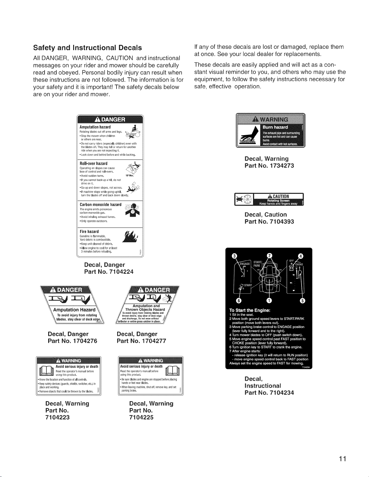
Safety and Instructional Decals
All DANGER, WARNING, CAUTION and instructional
messages on your rider and mower should be carefully
read and obeyed. Personal bodily injury can result when
these instructions are not followed. The information is for
your safety and it is important! The safety decals below
are on your rider and mower.
If any of these decals are lost or damaged, replace them
at once. See your local dealer for replacements.
These decals are easily applied and will act as a con-
stant visual reminder to you, and others who may use the
equipment, to follow the safety instructions necessary for
safe, effective operation.
Amputationhazard _,
Relating blades cut off arms and legs.
• Stop the mower when children
or others are nea£
• Do not carry riders (especially children) even with
the blades df. They may lall or return Ior another
ride when you are not expecbng d.
• Look down _nd behind before and while backing.
Roll=overhazard
Operating on slopes can cause
lose of control arid roll-overs.
• Avoid sudden turns.
• If you cannot back-up a hill, do Ilot
drive on it. r_,_
• Go up and down slopes, not across.
• If machine stops while going uphill,
turn the blades off and backdown slowly,
Carbon monoxide hazard _ _
The engi_le emits poisonous
carbon monoxide gas.
• Avoid inhaling exhaust fumes.
• Only operate outdoors.
Fire hazard
Gasoline is flammable.
Yard debris is combustible.
. Keep unit cleaned of debris.
. Allow engine to cool for at least
3 minutes before refueling.
Decal, Danger
Part No. 7104224
Decal, Warning
Part No. 1734273
Decal, Caution
Part No. 7104393
Decal, Danger
Part No. 1704276
/:
,'" aTv___ezs_ dd{{ ' r " "_ /'//
Decal, Danger
Part No. 1704277
Decal, Warning
Part No.
7104223
parking brake.
Decal, Warning
Part No.
7104225
Decal,
Instructional
Part No. 7104234
11

Decal, Ground
Speed Lever, L.H.
Part No. 7104226
Decal, Ground
Speed Lever, R.H.
Part No. 7104227
Decal, Control Panel,
L.H.
Part No. 7104232
Decal, Control Panel,
R.H.
Part No. 7104233
7104231J
Decal, Transmission
Release
Part No. 7104231
Safety Interlock System Tests
This unit is equipped with a Safety Interlock System.
Do not attempt to bypass or tamper with the switches/
devices.
TEST 1 -- ENGINE SHOULD NOT CRANK IF:
• Operator rises
• Operator rises
enaged, OR
• PTO switch is engaged, OR
• Parking brake is disengaged, OR
• Ground speed levers are not locked in their START/
PARK positions.
TEST 2-- ENGINE SHOULD CRANK IF:
• PTO switch is NOT engaged, AND
• Parking brake is engaged, AND
• Ground speed levers are locked into their
START/PARK positions.
TEST 3-- ENGINE SHOULD SHUT OFF IF:
off seat with PTO engaged, OR
off seat with parking brake dis-
• Operator rises off seat with ground speed levers not
locked in their START/PARK positions.
TEST 4 -- CHECK MOWER BLADE STOPPING TiME
The mower blades and mower drive belt should come
to a complete stop within five seconds after the electric
PTO switch is turned off (or operator rises off seat). If
mower drive belt does not stop within five seconds, see
your dealer.
NOTE: Once the engine has stopped, the PTO switch
must be turned off, the parking brake must be engaged,
and the ground speed levers must be locked in their
START/PARK positions in order to start the engine.
,AWARNING
if the unit does not pass a safety test, do not
operate it. See an authorized dealer.
Decal, Weight Limit
Part No. 7101940
12
(
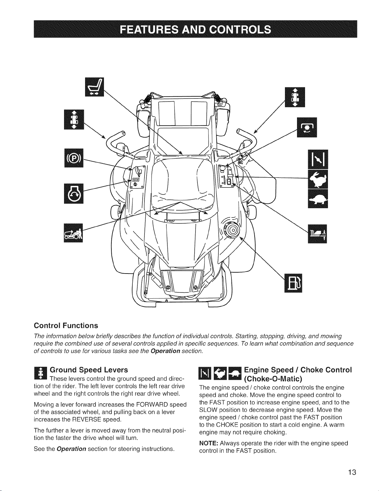
Control Functions
The information below briefly describes the function of individual controls. Starting, stopping, driving, and mowing
require the combined use of several controls applied in specific sequences. To learn what combination and sequence
of controls to use for various tasks see the Operation section.
Ground Speed Levers
These levers control the ground speed and direc-
tion of the rider. The left lever controls the left rear drive
wheel and the right controls the right rear drive wheel.
Moving a lever forward increases the FORWARD speed
of the associated wheel, and pulling back on a lever
increases the REVERSE speed.
The further a lever is moved away from the neutral posi-
tion the faster the drive wheel will turn.
See the Operation section for steering instructions.
Engine Speed / Choke Control
(Choke-O-IVlatic)
The engine speed / choke control controls the engine
speed and choke. Move the engine speed control to
the FAST position to increase engine speed, and to the
SLOW position to decrease engine speed. Move the
engine speed / choke control past the FAST position
to the CHOKE position to start a cold engine. A warm
engine may not require choking.
NOTE: Always operate the rider with the engine speed
control in the FAST position.
13

Ignition Switch
The ignition switch starts and stops the engine; it
has three positions:
_OFF
H RUN
Stops the engine and shuts off the
electrical system.
[I_START
Allows the engine to run and powers the
electrical system.
Cranks the engine for starting.
NOTE: Never leave the ignition switch in the RUN posi-
tion with the engine stopped-this drains the battery.
PTO Switch
The PTO (Power Take-Off) switch engages and
disengages the mower blade clutch. To engage the PTO,
pull UP on the switch. Push DOWN to disengage. Note
that the operator must be seated firmly in the rider seat
for the PTO to function.
Transmission Release Levers
The transmission release levers deactivate the
transmissions so that the unit can be pushed by hand
(see Pushing the Unit by Hand).
Seat Adjustment Lever
The seat can be adjusted forward and backward
(see Seat Adjustments).
Fuel Tank Cap
To remove the cap, turn counterclockwise.
Mower Cutting Height Adjustment
Switch
The mower cutting height is adjustable between 1-1/2"
(3,8 cm) and 3-3/4" (9,5 cm). See Cutting Height
Adjustment.
Parking Brake
Moving the parking brake lever forward and to the
right engages the parking brake. Moving the lever to the
left and back disengages the brake.
14
General Operating Safety
Before first time operation:
• Be sure to read all information in the Operator
Safety section before attempting to operate this rider
and mower.
• Become familiar with all of the controls and how to
stop the unit.
• Drive in an open area without mowing to become
accustomed to driving the unit.
WARNING
Never operate on slopes greater than 18 percent
(10°).
Select slow ground speed before driving onto
a slope. Use extra caution when operating on
slopes with a rear-mounted grass catcher.
Mow up and down slopes, not across the face,
use caution when changing directions and DO
NOT START OR STOP ON SLOPE.
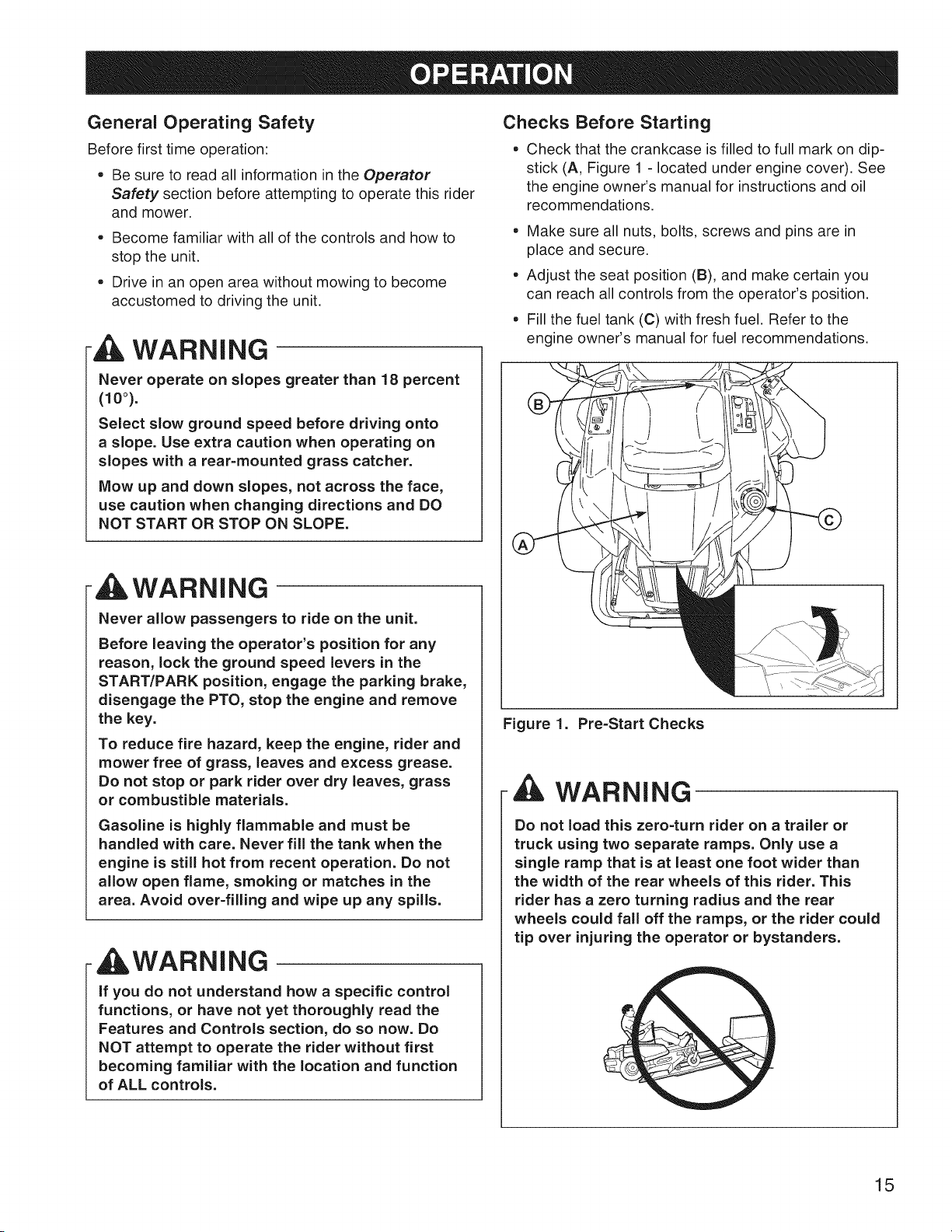
Checks Before Starting
° Check that the crankcase is filled to full mark on dip-
stick (A, Figure 1 - located under engine cover). See
the engine owner's manual for instructions and oil
recommendations.
° Make sure all nuts, bolts, screws and pins are in
place and secure.
° Adjust the seat position (B), and make certain you
can reach all controls from the operator's position.
• Fill the fuel tank (C) with fresh fuel. Refer to the
engine owner's manual for fuel recommendations.
AWARNING
Never allow passengers to ride on the unit.
Before leaving the operator's position for any
reason, lock the ground speed levers in the
START/PARK position, engage the parking brake,
disengage the PTO, stop the engine and remove
the key.
To reduce fire hazard, keep the engine, rider and
mower free of grass, leaves and excess grease.
Do not stop or park rider over dry leaves, grass
or combustible materials.
Gasoline is highly flammable and must be
handled with care. Never fill the tank when the
engine is still hot from recent operation. Do not
allow open flame, smoking or matches in the
area. Avoid over-filling and wipe up any spills.
WARNING
if you do not understand how a specific control
functions, or have not yet thoroughly read the
Features and Controls section, do so now. Do
NOT attempt to operate the rider without first
becoming familiar with the location and function
of ALL controls.
Figure 1. Pre-Start Checks
, WARNING
Do not load this zero=turn rider on a trailer or
truck using two separate ramps. Only use a
single ramp that is at least one foot wider than
the width of the rear wheels of this rider. This
rider has a zero turning radius and the rear
wheels could fall off the ramps, or the rider could
tip over injuring the operator or bystanders.
15
Starting the Engine
1. While sitting in the operator's seat, make sure the
PTO switch is disengaged, the parking brake is
engaged, and the ground speed levers are locked in
the START/PARK position.
2. Set the engine speed control to the CHOKE position.
NOTE: A warm engine may not require choking.
3. Insert the key into the ignition switch and turn it to
START.
4. After the engine starts, move the engine speed con-
trol back to the FAST position. Warm up the engine
by running it for at least a minute before engaging the
PTO switch or driving the rider.
5. After warming the engine, ALWAYS operate the
rider at FULL ENGINE SPEED when mowing.
in the event of an emergency the engine can be
stopped by simply turning the ignition switch to
STOP. Use this method only in emergency situations.
For normal engine shut down follow the procedure given
in Stopping the Rider and Engine.
Stopping the Rider and Engine
1. Return the ground speed levers to the middle (or
neutral 'IV') position to stop rider movement. Pivot the
levers outward to lock them in the START/PARK posi-
tion.
2. Disengage the PTO by pushing down on the PTO
switch.
3. Engage the parking brake by moving the parking
brake lever forward and to the right.
4. Move the engine speed control to the SLOW position
and turn the ignition key to OFF. Remove the key.
Mowing
1. Make sure the PTO switch is disengaged, the parking
brake is engaged, the ground speed levers are locked
in their START/PARK positions, and the operator is in
the seat.
2. Start the engine (see Starting the Engine).
3. Set the mower cutting height (see Cutting Height
Adjustment).
4. Set the engine speed control to FAST.
5. Disengage the parking brake.
6. Engage the PTO by pulling up on the switch,
7. Pivot the ground speed levers in from the START/
PARK position to the neutral 'N' position,
8. Begin mowing. See Operator Safety for tips on safe
mowing practices.
9. When finished, shut off the PTO.
10. Stop the engine (see Stopping the Rider and
Engine).
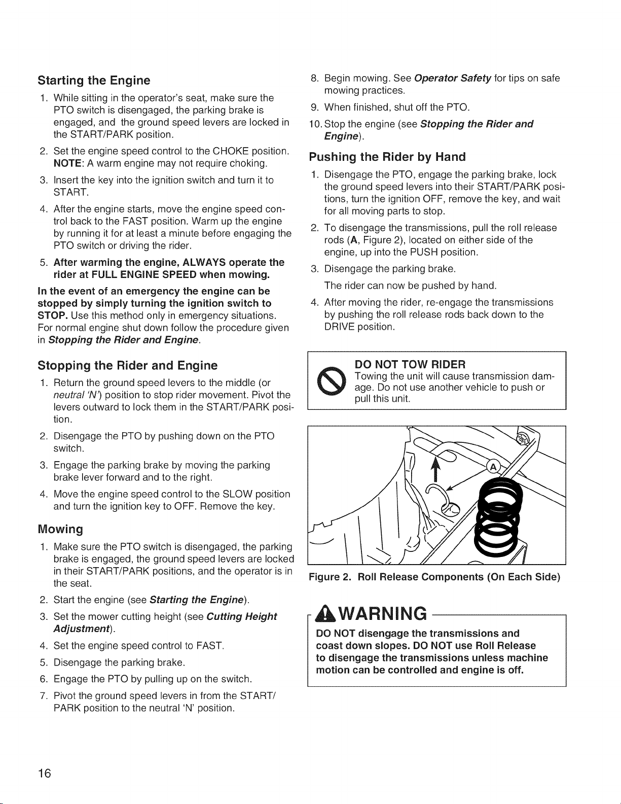
Pushing the Rider by Hand
1. Disengage the PTO, engage the parking brake, lock
the ground speed levers into their START/PARK posi-
tions, turn the ignition OFF, remove the key, and wait
for all moving parts to stop.
2. To disengage the transmissions, pull the roll release
rods (A, Figure 2), located on either side of the
engine, up into the PUSH position.
3. Disengage the parking brake.
The rider can now be pushed by hand.
4. After moving the rider, re-engage the transmissions
by pushing the roll release rods back down to the
DRIVE position.
DO NOT TOW RIDER
Towing the unit will cause transmission dam-
age. Do not use another vehicle to push or
pull this unit.
Figure 2. Roll Release Components (On Each Side)
WARNING
DO NOT disengage the transmissions and
coast down slopes. DO NOT use Roll Release
to disengage the transmissions unless machine
motion can be controlled and engine is off.
16
Zero Turn
Driving Practice
The ground speed levers of the zero turn rider are
responsive, and learning to gain a smooth and efficient
control of the rider's forward, reverse, and turning move-
ments will take some practice.
Spending some time going through the maneuvers shown
and becoming familiar with how the unit accelerates, trav-
els, and steers -- before you begin mowing -- is abso-
lutely essential to getting the most out of the zero turn
rider.
Locate a smooth, flat area of your lawn -- one with
plenty of room to maneuver. (Clear the area of objects,
people and animals before you begin.) Operate the
unit at mid-engine speed during this practice session
(ALWAYS operate at full engine speed when mowing),
and turn slowly to prevent tire slippage and damage to
your lawn.
We suggest you begin with the Smooth Travel proce-
dure to the right, and then advance through the forward,
reverse, and turning maneuvers.
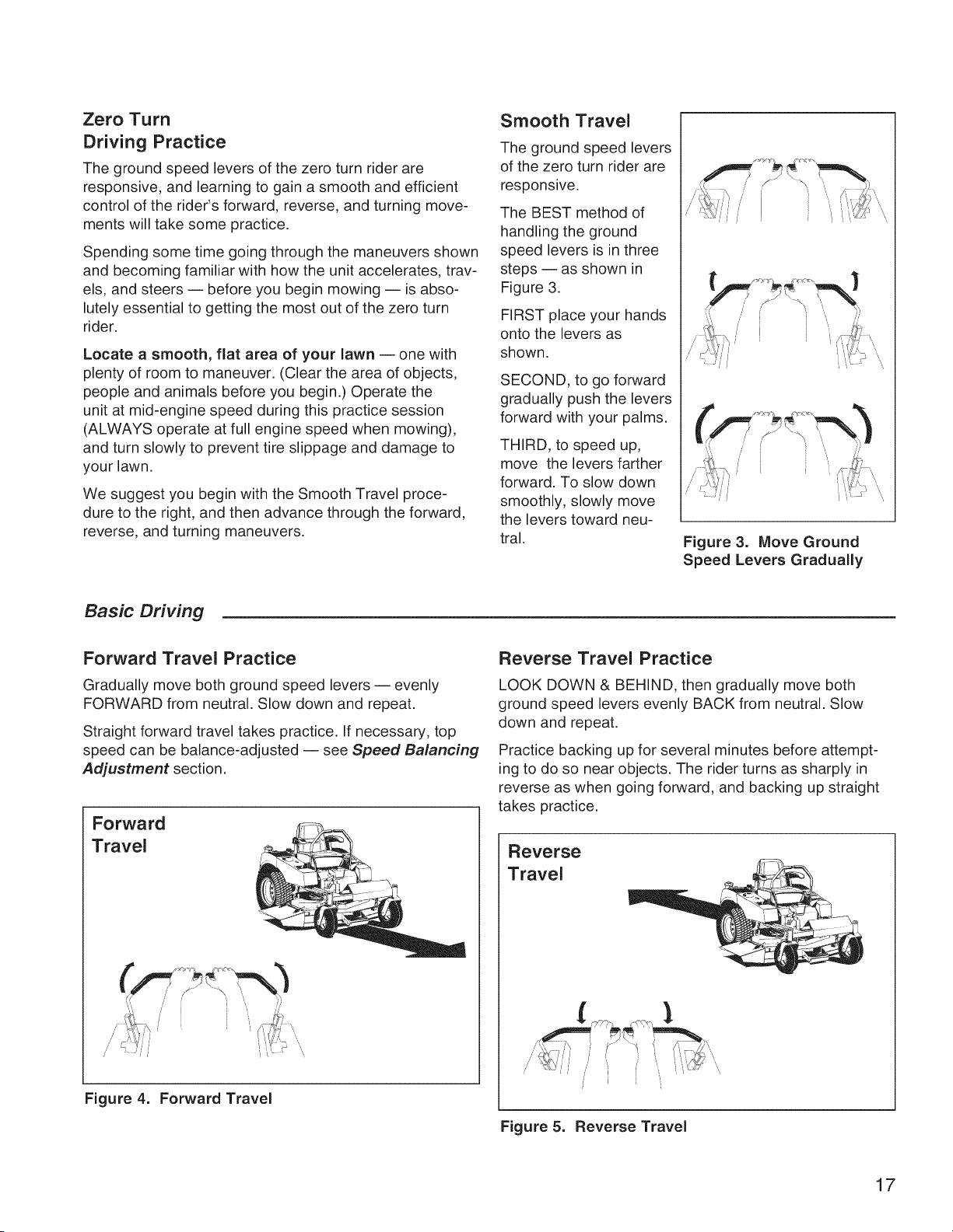
Smooth Travel
The ground speed levers
of the zero turn rider are
responsive.
The BEST method of
handling the ground
speed levers is in three
steps -- as shown in
Figure 3.
FIRST place your hands
onto the levers as
shown.
SECOND, to go forward
gradually push the levers
forward with your palms.
THIRD, to speed up,
move the levers farther
forward. To slow down
smoothly, slowly move
the levers toward neu-
tral.
\
\
Figure 3. Move Ground
Speed Levers Gradually
Basic Driving
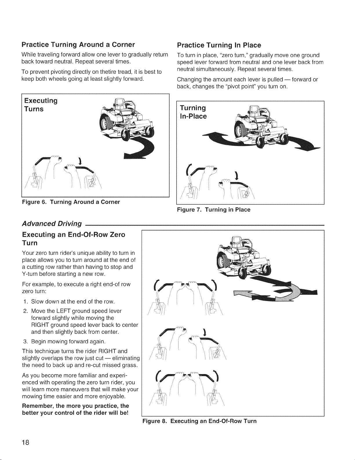
Forward Travel Practice
Gradually move both ground speed levers -- evenly
FORWARD from neutral. Slow down and repeat.
Straight forward travel takes practice. If necessary, top
speed can be balance-adjusted -- see Speed Balancing
Adjustment section.
Forward
Travel
Figure 4. Forward Travel
Reverse Travel Practice
LOOK DOWN & BEHIND, then gradually move both
ground speed levers evenly BACK from neutral. Slow
down and repeat.
Practice backing up for several minutes before attempt-
ing to do so near objects. The rider turns as sharply in
reverse as when going forward, and backing up straight
takes practice.
Reverse
Travel
Figure 5. Reverse Travel
17
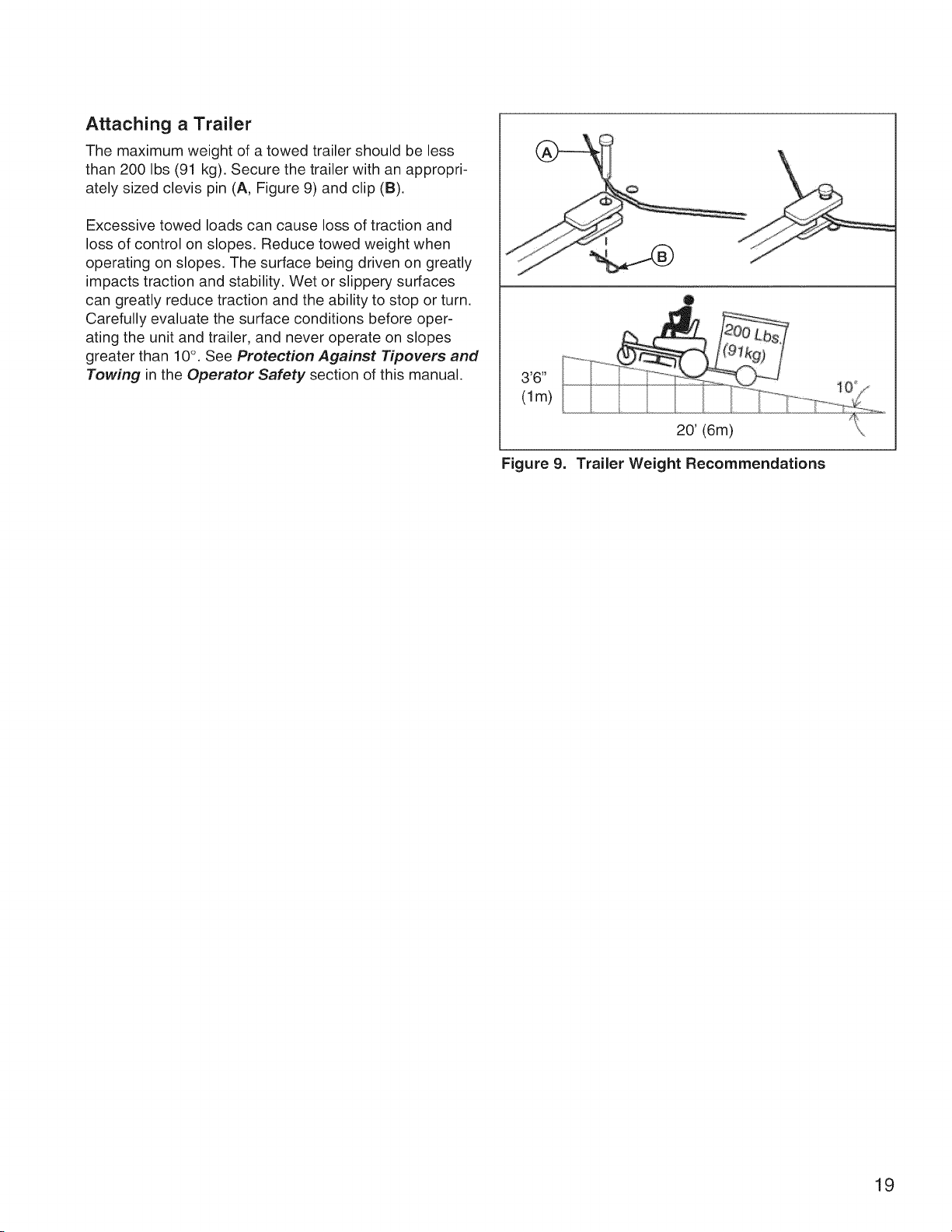
Practice Turning Around a Corner
While traveling forward allow one lever to gradually return
back toward neutral. Repeat several times.
To prevent pivoting directly on thetire tread, it is best to
keep both wheels going at least slightly forward.
Practice Turning in Place
To turn in place, "zero turn," gradually move one ground
speed lever forward from neutral and one lever back from
neutral simultaneously. Repeat several times.
Changing the amount each lever is pulled -- forward or
back, changes the "pivot point" you turn on.
Executing
Turns
Figure 6. Turning Around a Corner
Turning
In-Place
Figure 7. Turning in Place
Advanced Driving
Executing an End-Of=Row Zero
Turn
Your zero turn rider's unique ability to turn in
place allows you to turn around at the end of
a cutting row rather than having to stop and
Y-turn before starting a new row.
For example, to execute a right end-of row
zero turn:
,
2.
Slow down at the end of the row.
Move the LEFT ground speed lever
forward slightly while moving the
RIGHT ground speed lever back to center
and then slightly back from center.
3. Begin mowing forward again.
This technique turns the rider RIGHT and
slightly overlaps the row just cut -- eliminating
the need to back up and re-cut missed grass.
As you become more familiar and experi-
enced with operating the zero turn rider, you
will learn more maneuvers that will make your
mowing time easier and more enjoyable.
Remember, the more you practice, the
better your control of the rider will be!
Figure 8. Executing an End-Of-Row Turn
18
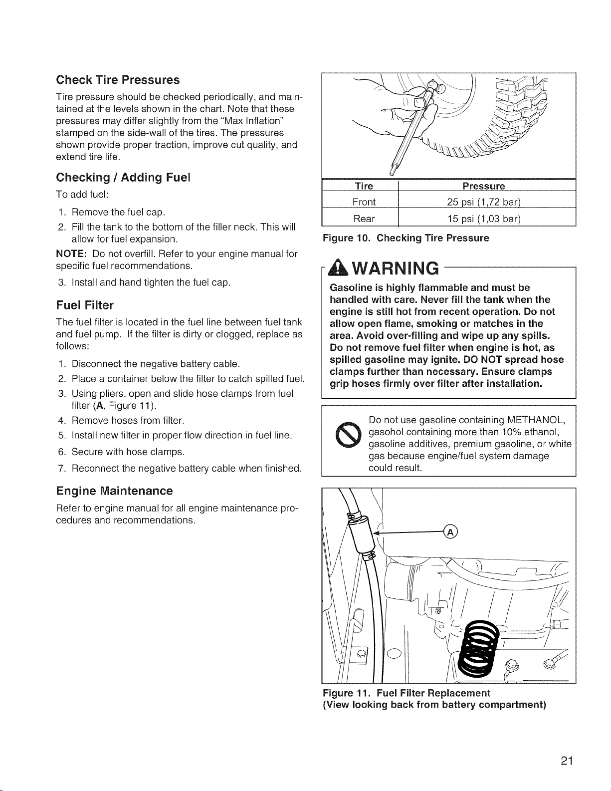
Attaching a Trailer
The maximum weight of a towed trailer should be less
than 200 Ibs (91 kg). Secure the trailer with an appropri-
ately sized clevis pin (A, Figure 9) and clip (B).
Excessive towed loads can cause loss of traction and
loss of control on slopes. Reduce towed weight when
operating on slopes. The surface being driven on greatly
impacts traction and stability. Wet or slippery surfaces
can greatly reduce traction and the ability to stop or turn.
Carefully evaluate the surface conditions before oper-
ating the unit and trailer, and never operate on slopes
greater than 10°. See Protection Against Tipovers and
Towing in the Operator Safety section of this manual,
Figure 9.
20' (6m)
Trailer Weight Recommendations
19

Maintenance Chart
ii!i i i! !i i i ! !i i ! i ! i i! !i !! ! i i ! ! i i i ! i! i! ! ! !i ii !i i !ii! !i !i !i ! J ii i ii iii ii iiiiiiiiiiiiiiiiiiiiiiiiiiiiiiiiiiiiiiiiiiiiiiiiiiiiiiiiiiiiiiiiiiiiiiiiiiiiiiiiiiiiiiiiiiiiiiiiiiiiiiiiiiiiiiiiiiiiiiiiiiiiiiiiiiiiiiiiiiiiiiiiiiiiiiiiiiiiiiiiiiiiiiiiiiiiiiiiiiiiiiiiiiiiiiiiiiiiiiiiiiiiiiiiiiiiiiiiiiiiiiiiiiiiiiiiiiiiiiiiiiiiiiiiiiiiiiiiiiiiiiiiiiiiiiiiiiiiiiiiiiiiiiiiiiiiiiiiiiiiiiiiiiiiiiiiiiiiiiiiiiiiiiiiiiiiiiiiiiiiiiiiiiiiiiiiiiiiiiiiiiiiiiiiiiiiiiiiiiiiiiiiiiiiiiiiiiiiiiiiiiiiiiiiiiiiiiiiiiiiiiiiiiiiiiiiiiiiiiiiiii !
m8 Hours or Daily
Check safety interlock system
Clean debris off rider and mower deck
Clean debris from engine compartment
Every 25 Hours or Annually *
Check tire pressure
Check mower blade stopping time
Check rider and mower for loose hardware
Every 50 Hours or Annually *
Check rider brakes
i
See Dealer Annually to
Lubricate rider and mower
Clean battery and cables
Check mower blades **
* Whichever comes first
** Check blades more often in regions with sandy soils or
high dust conditions,
i i! i i! !i i j i ii i i i i i i i i!i i i iiiiiii i i i i iiiiii iiiii iiiiiii iiiiiiiiiiiiiiiiiiiiiiiiiiiiiiiiiiiiiiiiiiiiiiiiiiiiiiiiiiiiiiiiiiiiiiii iiiiiiiiiiiiiiiiiiiiiiiiiiiiiiiiiiiiiiiiiiiiiiiiiiiiiiiiiiiiiiiiiiiii
First 5 Hours
Change engine oil
Every 8 Hours or Daily
Check engine oil level
Every 25 Hours or Annually
Clean engine air filter and pre-cleaner **
Every 50 Hours or Annually *
Change engine oil
Replace oil filter
Replace air filter
Replace pre-cleaner
See Dealer Annually to
Inspect muffler and spark arrester
Replace spark plug
Replace fuel filter
Clean engine air cooling system
* Whichever comes first
**Clean more often in dusty conditions or when airborne
debris is present.
20
Check Tire Pressures
Tire pressure should be checked periodically, and main-
tained at the levels shown in the chart. Note that these
pressures may differ slightly from the "Max Inflation"
stamped on the side-wall of the tires. The pressures
shown provide proper traction, improve cut quality, and
extend tire life.
Checking / Adding Fuel
To add fuel:
1. Remove the fuel cap.
2. Fill the tank to the bottom of the filler neck. This will
allow for fuel expansion.
NOTE: Do not overfill. Refer to your engine manual for
specific fuel recommendations.
3. Install and hand tighten the fuel cap.
Fuel Filter
The fuel filter is located in the fuel line between fuel tank
and fuel pump. If the filter is dirty or clogged, replace as
follows:
1. Disconnect the negative battery cable.
2. Place a container below the filter to catch spilled fuel.
3. Using pliers, open and slide hose clamps from fuel
filter (A, Figure 11 ).
4. Remove hoses from filter.
5. Install new filter in proper flow direction in fuel line.
6. Secure with hose clamps.
7. Reconnect the negative battery cable when finished.
Engine Maintenance
Refer to engine manual for all engine maintenance pro-
cedures and recommendations.
Tire Pressure
Front 25 psi (1,72 bar)
Rear 15 psi (1,03 bar)
Figure 10. Checking Tire Pressure
4 ,WARNING
Gasoline is highly flammable and must be
handled with care. Never fill the tank when the
engine is still hot from recent operation. Do not
allow open flame, smoking or matches in the
area. Avoid over-filling and wipe up any spills.
Do not remove fuel filter when engine is hot, as
spilled gasoline may ignite. DO NOT spread hose
clamps further than necessary. Ensure clamps
grip hoses firmly over filter after installation.
Do not use gasoline containing METHANOL,
gasohol containing more than 10% ethanol,
gasoline additives, premium gasoline, or white
gas because engine/fuel system damage
could result.
®
Figure 11. Fuel Filter Replacement
(View looking back from battery compartment)
21
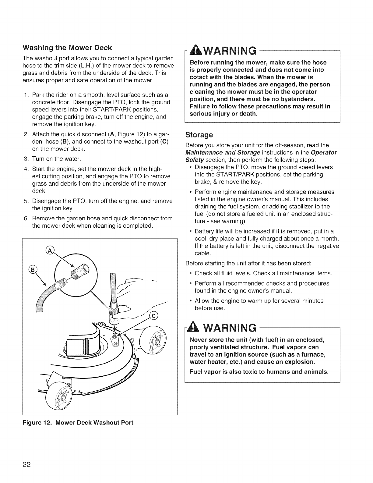
Washing the Mower Deck
The washout port allows you to connect a typical garden
hose to the trim side (L.H.) of the mower deck to remove
grass and debris from the underside of the deck. This
ensures proper and safe operation of the mower.
1. Park the rider on a smooth, level surface such as a
concrete floor. Disengage the PTO, lock the ground
speed levers into their START/PARK positions,
engage the parking brake, turn off the engine, and
remove the ignition key.
2. Attach the quick disconnect (A, Figure 12) to a gar-
den hose (B), and connect to the washout port (C)
on the mower deck.
3. Turn on the water.
4. Start the engine, set the mower deck in the high-
est cutting position, and engage the PTO to remove
grass and debris from the underside of the mower
deck.
5. Disengage the PTO, turn off the engine, and remove
the ignition key.
6. Remove the garden hose and quick disconnect from
the mower deck when cleaning is completed.
AWARNING
Before running the mower, make sure the hose
is properly connected and does not come into
cotact with the blades. When the mower is
running and the blades are engaged, the person
cleaning the mower must be in the operator
position, and there must be no bystanders.
Failure to follow these precautions may result in
serious injury or death.
Storage
Before you store your unit for the off-season, read the
Maintenance and Storage instructions in the Operator
Safety section, then perform the following steps:
° Disengage the PTO, move the ground speed levers
into the START/PARK positions, set the parking
brake, & remove the key.
° Perform engine maintenance and storage measures
listed in the engine owner's manual. This includes
draining the fuel system, or adding stabilizer to the
fuel (do not store a fueled unit in an enclosed struc-
ture - see warning).
° Battery life will be increased if it is removed, put in a
cool, dry place and fully charged about once a month.
If the battery is left in the unit, disconnect the negative
cable.
Before starting the unit after it has been stored:
• Check all fluid levels. Check all maintenance items.
• Perform all recommended checks and procedures
found in the engine owner's manual.
° Allow the engine to warm up for several minutes
before use.
WARNING
Never store the unit (with fuel) in an enclosed,
poorly ventilated structure. Fuel vapors can
travel to an ignition source (such as a furnace,
water heater, etc.) and cause an explosion.
Fuel vapor is also toxic to humans and animals.
Figure 12. Mower Deck Washout Port
22
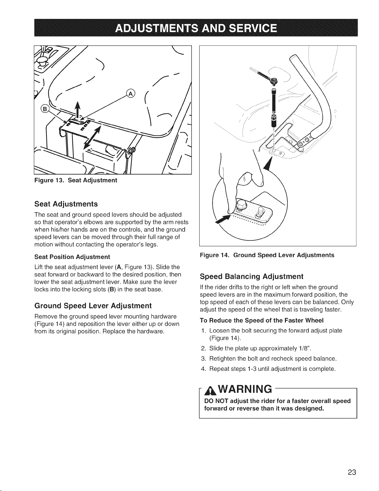
Figure 13. Seat Adjustment
Seat Adjustments
The seat and ground speed levers should be adjusted
so that operator's elbows are supported by the arm rests
when his/her hands are on the controls, and the ground
speed levers can be moved through their full range of
motion without contacting the operator's legs.
Seat Position Adjustment
Lift the seat adjustment lever (A, Figure 13). Slide the
seat forward or backward to the desired position, then
lower the seat adjustment lever. Make sure the lever
locks into the locking slots (B) in the seat base.
Ground Speed Lever Adjustment
Remove the ground speed lever mounting hardware
(Figure 14) and reposition the lever either up or down
from its original position. Replace the hardware.
\ /
/
\
Figure 14. Ground Speed Lever Adjustments
Speed Balancing Adjustment
If the rider drifts to the right or left when the ground
speed levers are in the maximum forward position, the
top speed of each of these levers can be balanced. Only
adjust the speed of the wheel that is traveling faster.
To Reduce the Speed of the Faster Wheel
1. Loosen the bolt securing the forward adjust plate
(Figure 14).
2. Slide the plate up approximately 1/8".
3. Retighten the bolt and recheck speed balance.
4. Repeat steps 1-3 until adjustment is complete.
AWARNING
DO NOT adjust the rider for a faster overall speed
forward or reverse than it was designed.
23
Cutting Height Adjustment
The cutting height adjustment switch controls the mower
cutting height. The cutting height is adjustable between
1-1/2" (3,8 cm) and 3-3/4" (9,5 cm).
To adjust cutting height:
Press the adjustment switch (A, Figure 15) forward to
lower the mower deck, backward to raise the mower
deck.
The slot in the cutting height indicator (B) indicates the
cutting height of the mower deck.
Mower Removal and Installation
NOTE: Perform mower installation and removal on a hard
flat surface such as a concrete floor.
Removal
1. Disengage the PTO, engage the parking brake, lock
the ground speed levers into their START/PARK posi-
tions, turn off the ignition, remove the key, and wait
for all moving parts to stop.
2. Place a 2 x 4 or similiar support under each end of
the mower deck, then lower the mower deck to its
lowest position. See Cutting Height Adjustment.
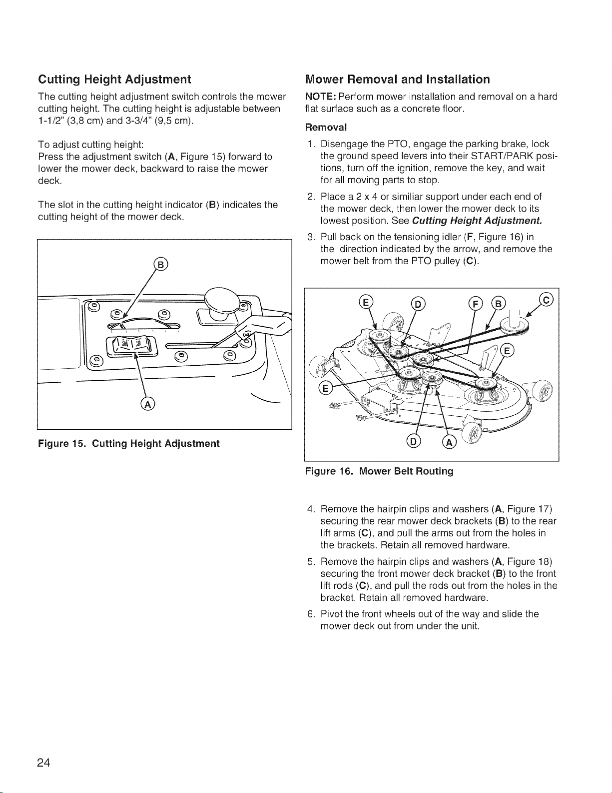
3. Pull back on the tensioning idler (F, Figure 16) in
the direction indicated by the arrow, and remove the
mower belt from the PTO pulley (C).
Figure 15. Cutting Height Adjustment
Figure 16. Mower Belt Routing
,
,
,
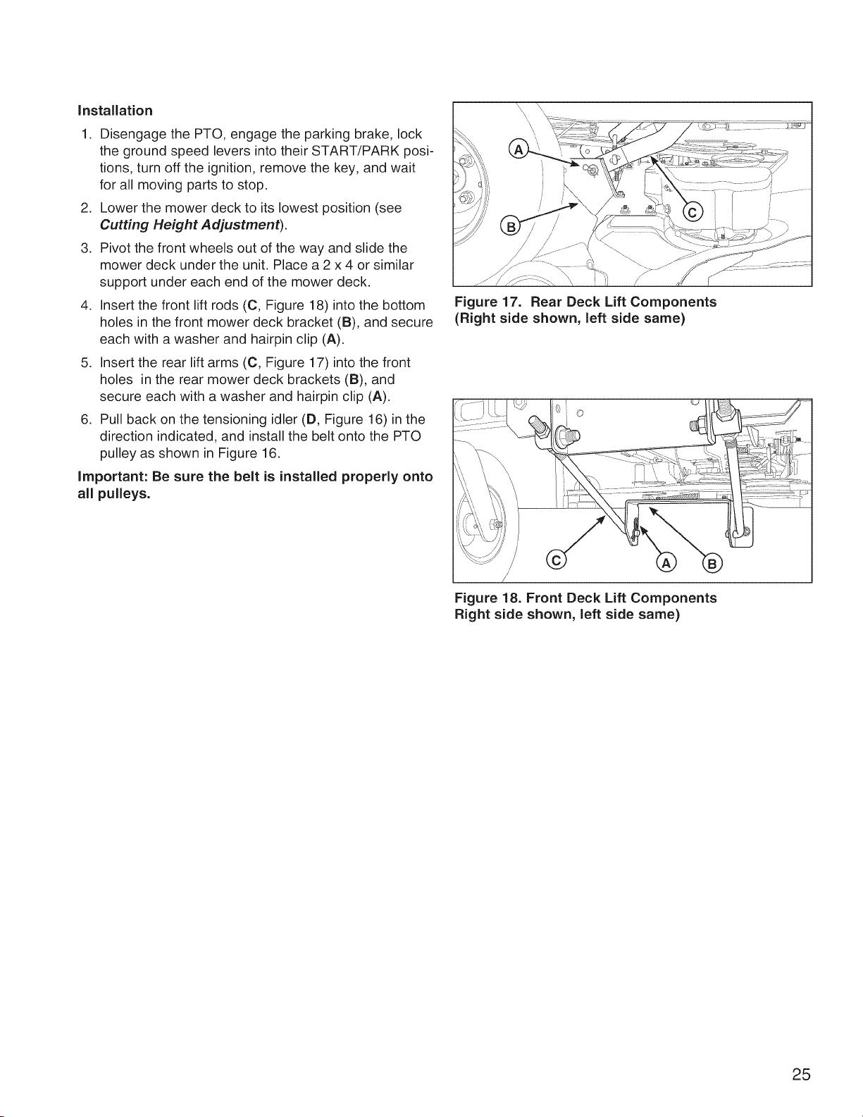
Remove the hairpin clips and washers (A, Figure 17)
securing the rear mower deck brackets (B) to the rear
lift arms (C), and pull the arms out from the holes in
the brackets. Retain all removed hardware.
Remove the hairpin clips and washers (A, Figure 18)
securing the front mower deck bracket (B) to the front
lift rods (C), and pull the rods out from the holes in the
bracket. Retain all removed hardware.
Pivot the front wheels out of the way and slide the
mower deck out from under the unit.
24
Installation
1. Disengage the PTO, engage the parking brake, lock
the ground speed levers into their START/PARK posi-
tions, turn off the ignition, remove the key, and wait
for all moving parts to stop.
2. Lower the mower deck to its lowest position (see
Cutting Height Adjustment).
3. Pivot the front wheels out of the way and slide the
mower deck under the unit. Place a 2 x 4 or similar
support under each end of the mower deck.
4. Insert the front lift rods (C, Figure 18) into the bottom
holes in the front mower deck bracket (B), and secure
each with a washer and hairpin clip (A).
5. Insert the rear lift arms (C, Figure 17) into the front
holes in the rear mower deck brackets (B), and
secure each with a washer and hairpin clip (A).
6. Pull back on the tensioning idler (D, Figure 16) in the
direction indicated, and install the belt onto the PTO
pulley as shown in Figure 16.
important: Be sure the belt is installed properly onto
all pulleys.
Figure 17. Rear Deck Lift Components
(Right side shown, left side same)
O
Figure 18. Front Deck Lift Components
Right side shown, left side same)
25
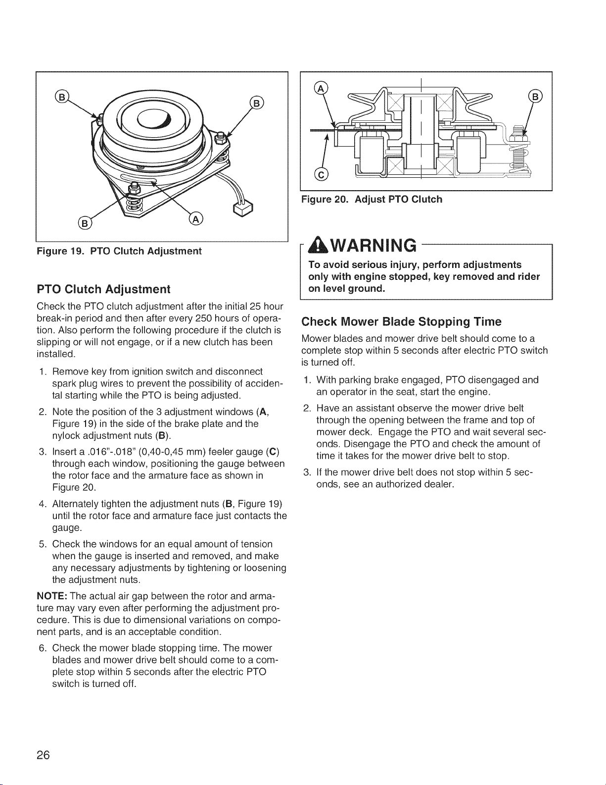
Figure 20. Adjust PTO Clutch
Figure 19. PTO Clutch Adjustment
PTO Clutch Adjustment
Check the PTO clutch adjustment after the initial 25 hour
break-in period and then after every 250 hours of opera-
tion. Also perform the following procedure if the clutch is
slipping or will not engage, or if a new clutch has been
installed.
1. Remove key from ignition switch and disconnect
spark plug wires to prevent the possibility of acciden-
tal starting while the PTO is being adjusted.
2. Note the position of the 3 adjustment windows (A,
Figure 19) in the side of the brake plate and the
nylock adjustment nuts (B).
3. Insert a .016"-.018" (0,40-0,45 mm) feeler gauge (C)
through each window, positioning the gauge between
the rotor face and the armature face as shown in
Figure 20.
4. Alternately tighten the adjustment nuts (B, Figure 19)
until the rotor face and armature face just contacts the
gauge.
5. Check the windows for an equal amount of tension
when the gauge is inserted and removed, and make
any necessary adjustments by tightening or loosening
the adjustment nuts.
NOTE: The actual air gap between the rotor and arma-
ture may vary even after performing the adjustment pro-
cedure. This is due to dimensional variations on compo-
nent parts, and is an acceptable condition.
6. Check the mower blade stopping time. The mower
blades and mower drive belt should come to a com-
plete stop within 5 seconds after the electric PTO
switch is turned off.
,WARNING
To avoid serious injury, perform adjustments
only with engine stopped, key removed and rider
on level ground.
Check Mower Blade Stopping Time
Mower blades and mower drive belt should come to a
complete stop within 5 seconds after electric PTO switch
is turned off.
1. With parking brake engaged, PTO disengaged and
an operator in the seat, start the engine.
2. Have an assistant observe the mower drive belt
through the opening between the frame and top of
mower deck. Engage the PTO and wait several sec-
onds. Disengage the PTO and check the amount of
time it takes for the mower drive belt to stop.
3. If the mower drive belt does not stop within 5 sec-
onds, see an authorized dealer.
26
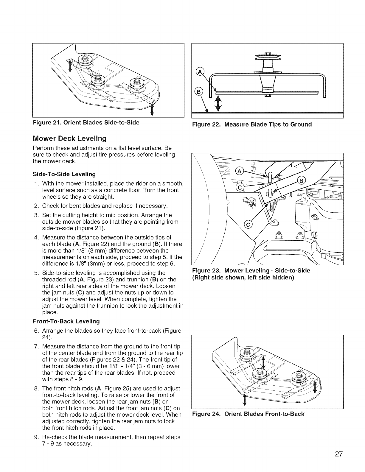
Figure 21. Orient Blades Side-to-Side
Figure 22. Measure Blade Tips to Ground
Mower Deck Leveling
Perform these adjustments on a flat level surface. Be
sure to check and adjust tire pressures before leveling
the mower deck.
Side-To-Side Leveling
1. With the mower installed, place the rider on a smooth,
level surface such as a concrete floor. Turn the front
wheels so they are straight.
2. Check for bent blades and replace if necessary.
3. Set the cutting height to mid position. Arrange the
outside mower blades so that they are pointing from
side-to-side (Figure 21 ).
4. Measure the distance between the outside tips of
each blade (A, Figure 22) and the ground (B). If there
is more than 1/8" (3 mm) difference between the
measurements on each side, proceed to step 5. If the
difference is 1/8" (3mm) or less, proceed to step 6.
5. Side-to-side leveling is accomplished using the
threaded rod (A, Figure 23) and trunnion (B) on the
right and left rear sides of the mower deck. Loosen
the jam nuts (C) and adjust the nuts up or down to
adjust the mower level. When complete, tighten the
jam nuts against the trunnion to lock the adjustment in
place.
Front=To=Back Leveling
6. Arrange the blades so they face front-to-back (Figure
24).
7. Measure the distance from the ground to the front tip
of the center blade and from the ground to the rear tip
of the rear blades (Figures 22 & 24). The front tip of
the front blade should be 1/8" - 1/4" (3 - 6 mm) lower
than the rear tips of the rear blades. If not, proceed
with steps 8 - 9.
8. The front hitch rods (A, Figure 25) are used to adjust
front-to-back leveling. To raise or lower the front of
the mower deck, loosen the rear jam nuts (B) on
both front hitch rods. Adjust the front jam nuts (C) on
both hitch rods to adjust the mower deck level. When
adjusted correctly, tighten the rear jam nuts to lock
the front hitch rods in place.
9. Re-check the blade measurement, then repeat steps
7 - 9 as necessary.
Figure 23. Mower Leveling - Side=to=Side
(Right side shown, left side hidden)
Figure 24. Orient Blades Front=to=Back
27
LOOSEN
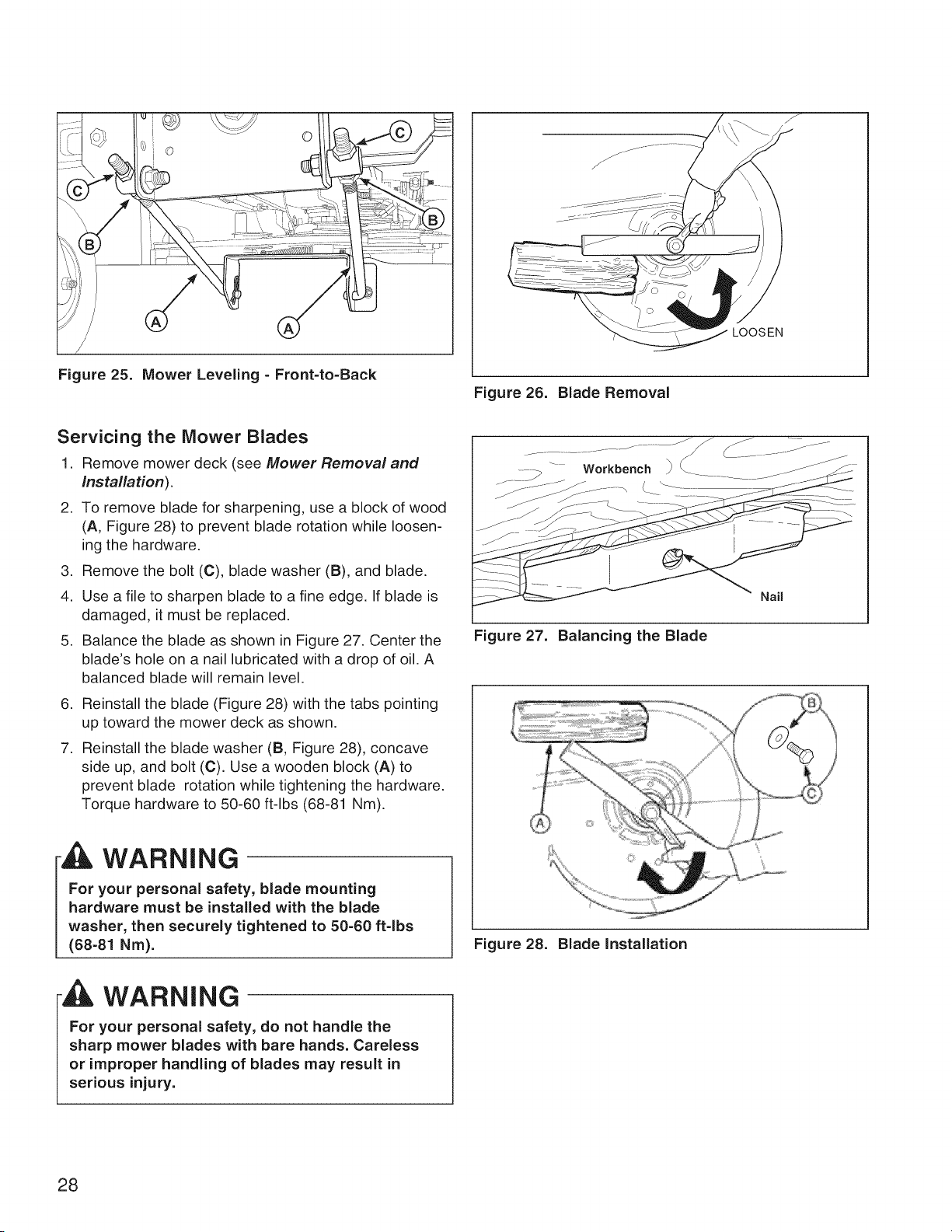
Figure 25. Mower Leveling - Front=to=Back
Figure 26. Blade Removal
Servicing the Mower Blades
1. Remove mower deck (see Mower Removal and
installation).
2. To remove blade for sharpening, use a block of wood
(A, Figure 28) to prevent blade rotation while loosen-
ing the hardware.
3. Remove the bolt (C), blade washer (B), and blade.
4. Use a file to sharpen blade to a fine edge. If blade is
damaged, it must be replaced.
5. Balance the blade as shown in Figure 27. Center the
blade's hole on a nail lubricated with a drop of oil. A
balanced blade will remain level.
6. Reinstall the blade (Figure 28) with the tabs pointing
up toward the mower deck as shown.
7. Reinstall the blade washer (B, Figure 28), concave
side up, and bolt (C). Use a wooden block (A) to
prevent blade rotation while tightening the hardware.
Torque hardware to 50-60 ft-lbs (68-81 Nm).
WARNING
I or your personal safety, blade mounting
hardware must be installed with the blade
washer, then securely tightened to 50=60 ft-lbs
(68-81 Nm).
WARNING
For your personal safety, do not handle the
sharp mower blades with bare hands. Careless
or improper handling of blades may result in
serious injury.
Nail
Figure 27. Balancing the Blade
Figure 28. Blade Installation
28

Lubrication
Lubricate the unit at the points shown in Figure 29, as
well as the others listed in this section
Grease:
• front caster wheel axles
r_ . front caster spindle bosses
• front axle center pivot
• mower blade spindles *
• mower deck idler arm
• mower deck lift motor screw (located up under
right fender)
Use grease fittings when present Disassemble parts to
apply grease to moving parts when grease fittings are not
installed
Not all greases are compatible Use automotive-type
lithium grease
* Some blade spindles have grease fittings above the
mower deck, while others have grease fittings below the
deck
Oil:
l
• ground speed lever pivot points
• discharge chute hinge
• deck lift pivot points
Generally, all moving metal parts should be oiled where
contact is made with other parts Keep oil and grease
off belts and pulleys Remember to wipe fittings and sur-
faces clean both before and after lubrication
2x
\
\
Figure 29. Lubrication Points (Grease)
29
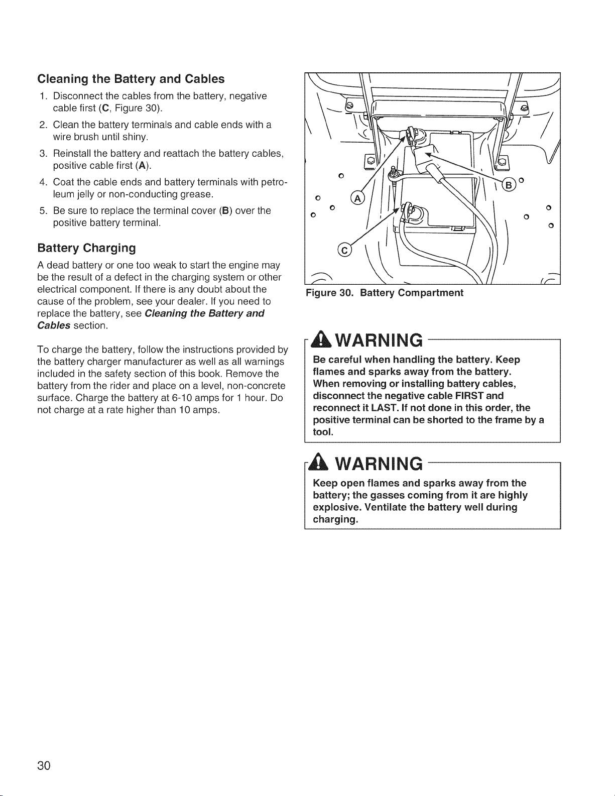
Cleaning the Battery and Cables
1. Disconnect the cables from the battery, negative
cable first (C, Figure 30).
2. Clean the battery terminals and cable ends with a
wire brush until shiny.
3. Reinstall the battery and reattach the battery cables,
positive cable first (A).
4. Coat the cable ends and battery terminals with petro-
leum jelly or non-conducting grease.
5. Be sure to replace the terminal cover (B) over the
positive battery terminal.
Battery Charging
A dead battery or one too weak to start the engine may
be the result of a defect in the charging system or other
electrical component. If there is any doubt about the
cause of the problem, see your dealer. If you need to
replace the battery, see Cleaning the Battery and
Cables section.
To charge the battery, follow the instructions provided by
the battery charger manufacturer as well as all warnings
included in the safety section of this book. Remove the
battery from the rider and place on a level, non-concrete
surface. Charge the battery at 6-10 amps for 1 hour. Do
not charge at a rate higher than 10 amps.
Figure 30. Battery Compartment
,WARNING
Be careful when handling the battery. Keep
flames and sparks away from the battery.
When removing or installing battery cables,
disconnect the negative cable FIRST and
reconnect it LAST. if not done in this order, the
positive terminal can be shorted to the frame by a
tool.
WARNING
Keep open flames and sparks away from the
battery; the gasses coming from it are highly
explosive. Ventilate the battery well during
charging.
30
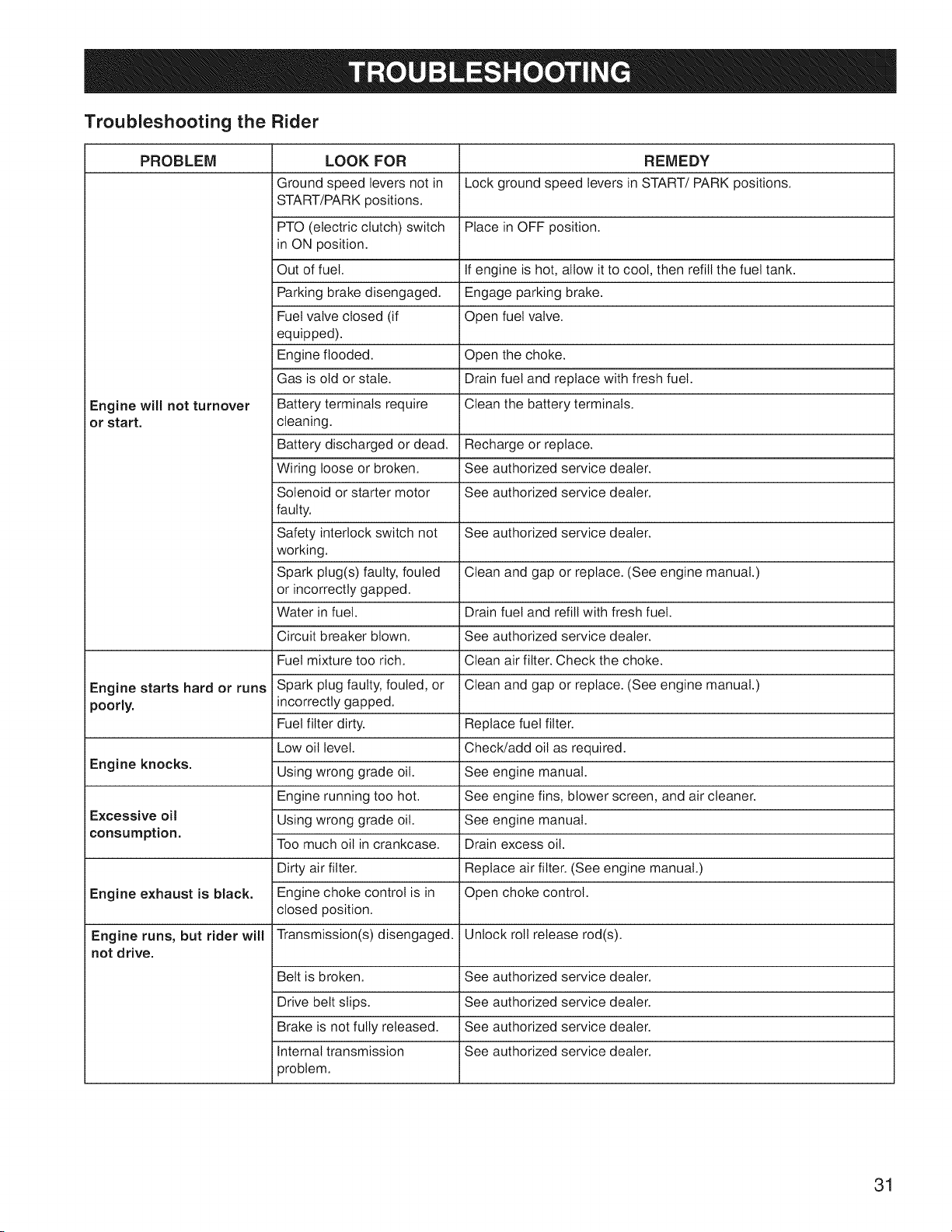
Troubleshooting the Rider
PROBLEM LOOK FOR REMEDY
Ground speed levers not in Lock ground speed levers in START/PARK positions.
START/PARK positions.
PTO (electric clutch) switch Place in OFF position.
in ON position.
Out of fuel. If engine is hot, allow it to cool, then refill the fuel tank.
Parking brake disengaged. Engage parking brake.
Fuel valve closed (if Open fuel valve.
equipped).
Engine flooded. Open the choke.
Gas is old or stale. Drain fuel and replace with fresh fuel.
Engine witl not turnover Battery terminals require Clean the battery terminals.
or start, cleaning.
Battery discharged or dead. Recharge or replace.
Wiring loose or broken. See authorized service dealer.
Solenoid or starter motor See authorized service dealer.
faulty.
Safety interlock switch not See authorized service dealer.
working.
Spark plug(s) faulty, fouled Clean and gap or replace. (See engine manual.)
or incorrectly gapped.
Water in fuel. Drain fuel and refill with fresh fuel.
Circuit breaker blown. See authorized service dealer.
Fuel mixture too rich. Clean air filter. Check the choke.
Engine starts hard or runs Spark plug faulty, fouled, or Clean and gap or replace. (See engine manual.)
poorly, incorrectly gapped.
Fuel filter dirty. Replace fuel filter.
Low oil level. Check/add oil as required.
Engine knocks.
Using wrong grade oil. See engine manual.
Engine running too hot. See engine fins, blower screen, and air cleaner.
Excessive oil Using wrong grade oil. See engine manual.
consumption.
Too much oil in crankcase. Drain excess oil.
Dirty air filter. Replace air filter. (See engine manual.)
Engine exhaust is black. Engine choke control is in Open choke control.
closed position.
Engine runs, but rider will Transmission(s) disengaged. Unlock roll release rod(s).
not drive.
Belt is broken. See authorized service dealer.
Drive belt slips. See authorized service dealer.
Brake is not fully released. See authorized service dealer.
Internal transmission See authorized service dealer.
problem.
31

PROBLEM LOOK FOR REMEDY
Pulleys or belt greasy or oily. Clean as required.
i Rider drive belt slips. Belt stretched or worn. See authorized service dealer.
Brake components worn or See authorized service dealer.
damaged.
Brake will not hold.
Internal transmission See authorized service dealer.
problem.
Steering linkage is loose. Check and tighten any loose connections.
Rider steers or handles
poorly. Improper tire inflation. See Maintenance section.
Troubleshooting the Mower
PROBLEM LOOK FOR REMEDY
Mower deck not properly Unlock roll release rod(s).
installed.
Mower will not raise.
Deck lift components See authorized service dealer.
damaged.
Mower not leveled properly. See Mower Adjustment.
Mower cut is uneven. Rider tires not inflated See Maintenance section.
equally or properly.
Engine speed too slow. See engine speed control to FAST.
Ground speed too fast. Decrease ground speed.
Blades are dull. Sharpen or replace blades. See Servicing the Mower Blades.
Mower cut is rough
looking. Mower drive belt slipping See authorized service dealer.
because it is oily or worn.
Blades not properly fastened See Servicing the Mower Blades.
to spindles.
Engine speed too slow. Set engine speed control to FAST.
Ground speed too fast. Decrease ground speed.
Engine stalls easily with Cutting height set too low. Cut tall grass at maximum cutting.height during first pass.
i mower engaged.
Discharge chute jamming Cut grass with discharge pointing toward previously cut area.
with cut grass.
Blade mounting hardware is Tighten to 50-60 ft-lbs (68-81 Nm).
loose.
Mower blades, spindles, or See authorized service dealer.
Excessive mower pulleys are bent.
vibration.
Mower blades are out of Remove, sharpen, and balance blades. See Servicing the Mower
balance. Blades.
Blade installed incorrectly. See authorized service dealer.
Excessive belt wear or Bent or rough pulleys. See authorized service dealer.
breakage. Using incorrect belt. See authorized service dealer.
Mower drive belt slips or Idler pulley spring broken or See authorized service dealer.
fails to drive, not properly attached.
Mower drive belt broken. See authorized service dealer.
32
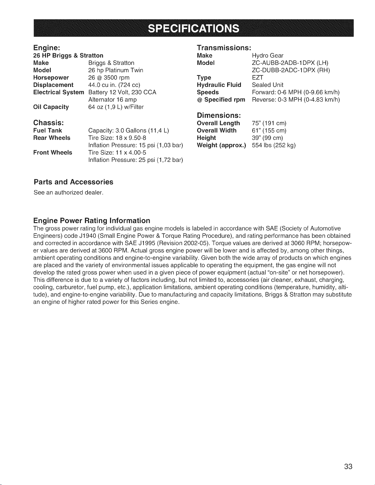
Engine:
26 HP Briggs & Stratton
Make
Model
Horsepower
Displacement
Electrical System
Oil Capacity
Briggs & Stratton
26 hp Platinum Twin
26 @ 3500 rpm
44.0 cu in. (724 cc)
Battery 12 Volt, 230 CCA
Alternator 16 amp
64 oz (1,9 L) w/Filter
Transmissions:
Make
Model
Front Wheels
Type
Hydraulic Fluid
Speeds
@ Specified rpm
Hydro Gear
ZC-AUBB-2ADB-1DPX (LH)
ZC-DUBB-2ADC-1DPX (RH)
EZT
Sealed Unit
Forward: 0-6 MPH (0-9.66 km/h)
Reverse: 0-3 MPH (0-4.83 km/h)
Dimensions:
Chassis: Overall Length 75" (191 cm)
Fuel Tank Capacity: 3.0 Gallons (11,4 L) Overall Width 61" (155 cm)
Rear Wheels Tire Size: 18 x 9.50-8 Height 39" (99 cm)
Inflation Pressure: 15 psi (1,03 bar) Weight (approx.) 554 Ibs (252 kg)
Tire Size: 11 x 4.00-5
Inflation Pressure: 25 psi (1,72 bar)
Parts and Accessories
See an authorized dealer.
Engine Power Rating Information
The gross power rating for individual gas engine models is labeled in accordance with SAE (Society of Automotive
Engineers) code J1940 (Small Engine Power & Torque Rating Procedure), and rating performance has been obtained
and corrected in accordance with SAE J1995 (Revision 2002-05). Torque values are derived at 3060 RPM; horsepow-
er values are derived at 3600 RPM. Actual gross engine power will be lower and is affected by, among other things,
ambient operating conditions and engine-to-engine variability. Given both the wide array of products on which engines
are placed and the variety of environmental issues applicable to operating the equipment, the gas engine will not
develop the rated gross power when used in a given piece of power equipment (actual "on-site" or net horsepower).
This difference is due to a variety of factors including, but not limited to, accessories (air cleaner, exhaust, charging,
cooling, carburetor, fuel pump, etc.), application limitations, ambient operating conditions (temperature, humidity, alti-
tude), and engine-to-engine variability. Due to manufacturing and capacity limitations, Briggs & Stratton may substitute
an engine of higher rated power for this Series engine.
33

CRAFTSMAN TWO YEAR FULL WARRANTY
FOR TWO YEARS from the date of purchase, if any non-expendable part of this riding equipment fails due
to a defect in matedai or workmanship, visit www.craftsman.com or call 1-800-659-5917 to arrange for free
in-home repair.
The frame and front axle will be repaired free of charge for five years from the date of purchase if defective in
material or workmanship.
In all cases, if repair proves impossible, the riding equipment will be replaced free of charge with the same or
an equivalent model.
The battery will be replaced free of charge for 90 days from the date of purchase if defective in material or
workmanship (our testing proves that it will not hold a charge).
This warranty is void if this product is ever used while providing commercial services or if rented to another
person.
This warranty covers ONLY defects in material and workmanship. Warranty coverage does NOT
include:
o
o
Expendable items that can wear out from normal use within the warranty period, including but not limited
to blades, spark plugs, air cleaners, belts, and oil filters.
Standard maintenance servicing, oil changes, or tune-ups.
Tire replacement or repair caused by punctures from outside objects, such as nails, thorns, stumps, or
glass.
Tire or wheel replacement or repair resulting from normal wear, accident, or improper operation or
maintenance.
Repairs necessary because of operator abuse, including but not limited to damage caused by towing
objects beyond the capability of the riding equipment, impacting objects that bend the frame or crank-
shaft, or over-speeding the engine.
Repairs necessary because of operator negligence, including but not limited to, electrical and mechani-
cal damage caused by improper storage, failure to use the proper grade and amount of engine oil, failure
to keep the deck clear of flammable debris, or failure to maintain the riding equipment according to the
instructions contained in the operator's manual.
• Engine (fuel system) cleaning or repairs caused by fuel determined to be contaminated or oxidized
(stale). In general, fuel should be used within 30 days of its purchase date.
• Normal deterioration and wear of the exterior finishes, or product label replacement.
This warranty gives you specific legal rights, and you may also have other rights which vary from state to
state.
Sears Brands Management Corporation, Hoffman Estates, IL 60179
34

Congratulations on making a smart purchase.
Your new Craftsman@ product is designed and
manufactured for years of dependable operation. But
like all products, it may require repair from time to time.
That's when having a Repair Protection Agreement can
save you money and aggravation.
Here's what the Repair Protection Agreement*
includes:
[] Expert service by our 10,000 professional repair
specialists
[] Unlimited service and no charge for parts and
labor on all covered repairs
[] Product replacement up to $1500 if your covered
product can't be fixed
[] Discount of 10% from regular price of service
and related installed parts not covered by the
agreement; also, 10% off regular price of preventive
maintenance check
[] Fast help by phone - we call it Rapid Resolution -
phone support from a Sears representative. Think of
us as a "talking owner's manual."
Once you purchase the Repair Protection Agreement, a
simple phone call is all that it takes for you to schedule
service. You can call anytime day or night, or schedule a
service appointment online.
The Repair Protection Agreement is a risk-free purchase.
If you cancel for any reason during the product warranty
period, we will provide a full refund. Or, a prorated
refund anytime after the product warranty period expires.
Purchase your Repair Protection Agreement today!
Some limitations and exclusions apply. For prices
and additional information in the U.S.A. call 1°800°
827=6655.
*Coverage in Canada varies on some items. For full
details call Sears Canada at 1o800o361°6665.
Sears Installation Service
For Sears professional installation of home appliances,
garage door openers, water heaters, and other major
home items, in the U.S.A. or Canada call 1=800-4=MY=
HOME@.
35

36

PTS - I
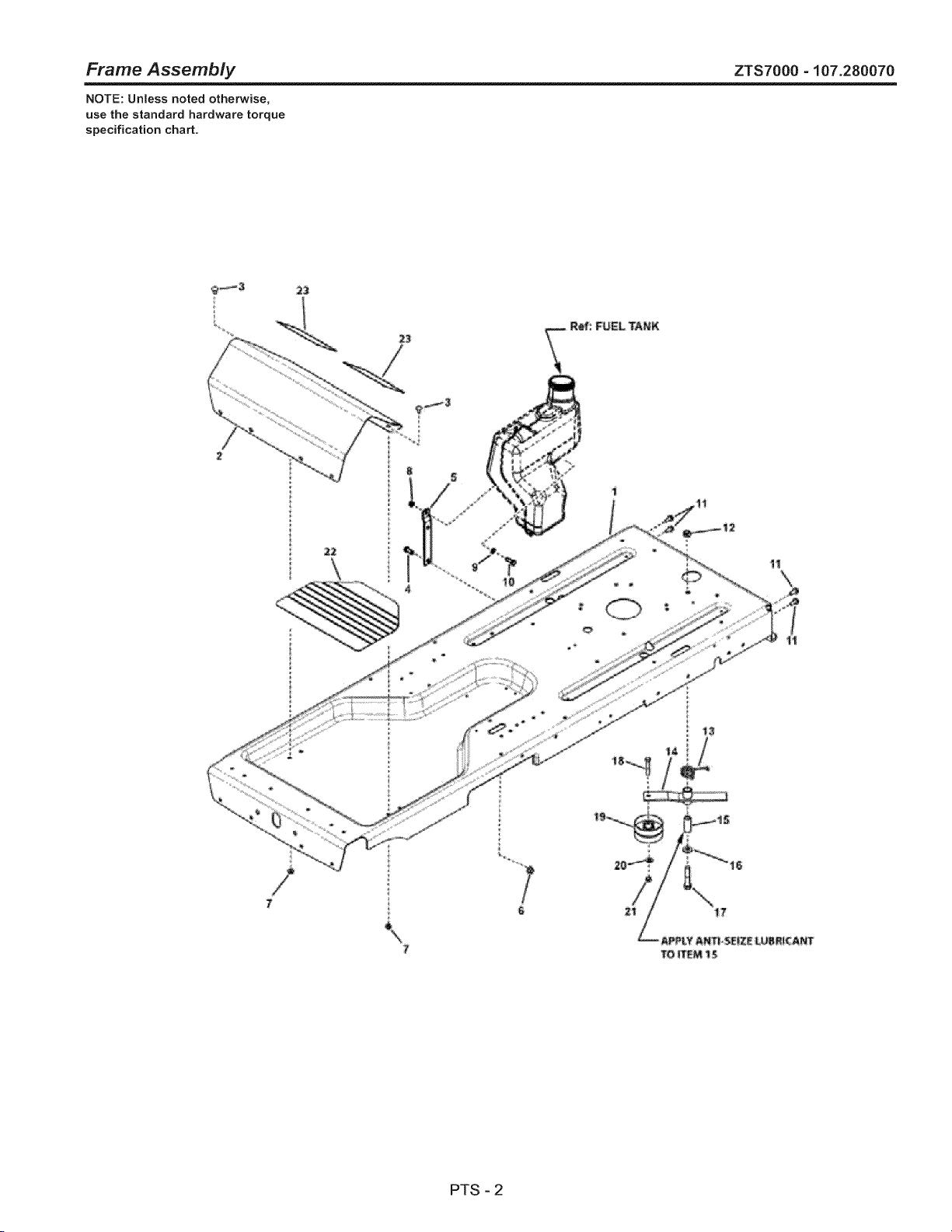
Frame Assembly ZTS7000 - 107.280070
NOTE: Unless noted otherwise,
use the standard hardware torque
specification chart.
t
PTS - 2

Frame Assembly
REF NO PART NO. QTY.
1 7301073BNYP 1
2 7300140BNYP 1
3 7090799SM 2
4 7091086YP 1
5 7301110BMYP 1
6 1931211SM 1
7 7091601SM 2
8 7091298YP 1
9 017X47MA 1
10 7027168SM 1
11 7091541SM 4
12 7091894SM 1
13 7044760SM 1
14 7400208BMYP 1
15 7200034SM 1
16 7091587SM 1
17 7091218SM 1
18 7091305SM 1
19 7100103SM 1
20 7090122YP 1
21 7091585SM 1
22 7103830YP 1
23 7014048YP 2
ZTS7000 - 107.280070
DESCRiPTiON
FRAME, RZT
FOOTREST
BOLT, 5/16-18 x 5/8" Round Head Short Square Neck Carriage, GR 5
SCREW, 3/8-16 x 3!4" Hex Head Cap, GR 5 ZP
BRACKET, Support, Fuel Tank
NUT, 3/8-16 Hex Flange lock, GR F, BZ
NUT, 5/16-18, Hex Flange Lock, GR 5
NUT, 5/16-18- Nyloc, YZ
WASHER, .34 x .62 x 16 Ga, Flat
SCREW, 5/16-18 x 1" Hex Head Cap, GR 5, YZ
SCREW, 5/16-18 x 3/4" Hex Washer Self-Tap, YZ
NUT, 1/2-13 Hex Center Lock, GR 5, YZ
SPRING, Torsion, RH Wind
WELDMENT, Hydro Idler MY08
SPACER, Hydro Idler
WASHER, .531 x 1.062 x .121, Flat, YZ (SAE)
SCREW, 1/2-13 x 2-1/2", Hex Head Cap, GR 5 (Black Phosphate)
SCREW, 3/8-16 x 2" Hex Head Cap, GR 5, YZ
IDLER, 3.25" OD x .391 ID x 1.63, Backside
WASHER, 3/8" Flat (SAE)
NUT, 3/8-16 Hex Center Lock, YZ
MAT, Floor Pan, RZT
FOOT PAD, Wide
Footnotes
PTS - 3
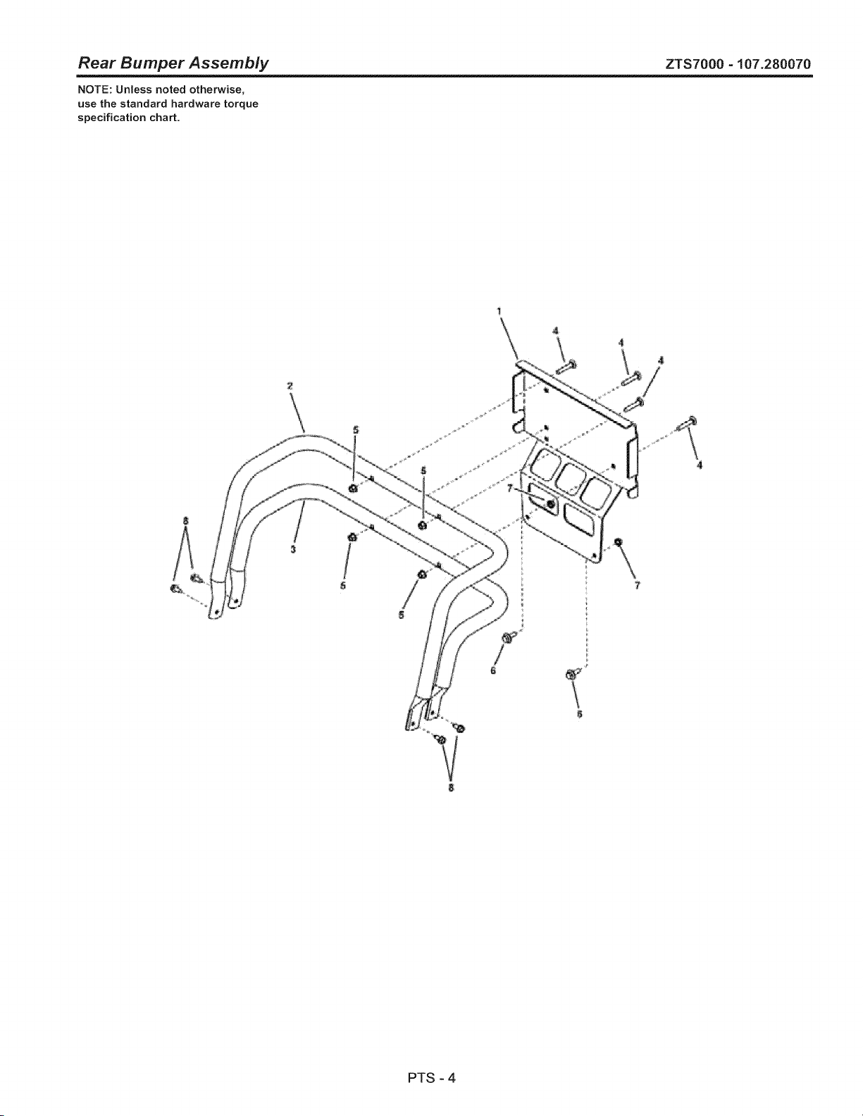
Rear Bumper Assembly ZTS7000 - 107.280070
NOTE: Unless noted otherwise,
use the standard hardware torque
specification chart.
PTS - 4

Rear Bumper Assembly
REF NO PART NO. QTY.
1 7301121BNYP 1
2 7301123BMYP 1
3 7301124BMYP 1
4 1931338SM 4
5 1960686SM 4
6 1716654SM 2
7 1927557SM 2
8 1664847SM 4
DESCRIPTION
PLATE, Brand
TUBE, Bumper, Upper, 285Z
TUBE, Bumper, Lower, 285Z
BOLT, 5/16-18 x 1-3/4" Round Head Short Square Neck
NUT, 5/16-18 Hex Flange Nyloc
BOLT, Shoulder
NUT, 5/16-18 Hex Flange Lock, Large, Black
SCREW, 5/16-18 x 3/4" Hex Washer Head Self-Tap, Black
ZTS7000-107.280070
Footnotes
PTS - 5

Engine Group, B&S V-Twin ZTS7000-107.280070
NOTE: Unless noted otherwise,
use the standard hardware torque
specification chart.
, "_i '> _ _
<
\
PTS - 6
Engine Group, B&S V-Twin
REF NO PART NO. QTY.
1 7090999SM 12
2 7103888YP 1
3 7091017YP 1
4 7091018YP 1
5 7301084BMYP 1
6 7301093BMYP 1
7 7103815YP 1
8 1715917SM 1
9 7103536YP 1
10 1726400SM 1
11 7029900SM 2
12 7103771YP 1
13 7012080SM 4
14 7200140YP 1
15 7091511SM 1
16 7091315SM 5
17 7090188SM 3
18 7091584SM 1
19 1930591SM 2
20 7103414YP 1
21 1731214SM 2
22 7091738SM 4
23 1726498SM 1
24 7091318SM 1
25 7900020SM 1
26 7091601SM 1
27 7013847YP 2
28 7091908YP 1
29 7090324SM 3
30 7103411YP 1
31 1935255SM 2
32 7301083YP 1
33 7091198SM 2
34 7043343SM 1
35 7016755YP 1
36 7091575SM 1
37 7011763SM 1
38 1717664SM 1
39 1737462YP 1
40 7091904YP 1
41 7029138SM 1
42 7091301YP 1
43 7092130SM 1
ZTS7000 - 107.280070
DESCRiPTiON
SCREW, Pan Head Taptite Torx, 1/4-20 x 5/8
KNOB, Throttle, Red
SCREW, #8-32 x 3/8" Cross Recess Filister Head, GR 2
NUT, #8-32 Hex, GR 2B
PANEL, Control, LH
PANEL, Control, RH
ASSEMBLY, Fuel Tank, 3 Gallon (Incl. Ref. 8, 9 & 10)
CAP, Fuel Tank (Included with Ref. No. 7)
ASSEMBLY, Fuel Hose (Included with Ref. No. 7)
BUSHING, Fuel (Included with Ref. No. 7)
CLAMP, Fuel Hose
ASSEMBLY, Throttle, Choke-A-Matic, B&S V-Twin
CABLE TIE, 7"
HOSE, Fuel
NUT, 5/16-18 Hex, GR 5 or B, YZ
WASHER, 5/16" Split Lock
WASHER, 5/16" Flat
NUT, 1/4-20 Hex Flange Lock, GR 5, YZ
SCREW, 5!16-18 x 3/4" Hex Flange Lock, Black
MANIFOLD, B&S V-Twin
GASKET, Exhaust B&S Reg (No Chre) 273485
SET SCREW, 5!16-18 x 3/4" Socket Head, GR 8 Black
HOSE, Oil Drain
SCREW, 5/16-18 x 3/4" Hex Head Cap, GR 5, YZ
HARNESS CLIP, 5/8"
NUT, 5/16-18 Flange Lock, YZ
RETAINER, 3/8" Bolt
SCREW, 5/16-18 x 1-3/4" Hex Head Cap, GR 5 YZ
SCREW, 3/8-16 x 1" Hex Washer Self-Tap
MUFFLER, RZT
SPEEDNUT, 5/16 -18, Lug Type .025/.150 B
HEAT SHIELD, Muffler
SCREW, 3/8-16 x 5/8" Hex Washer Self-Tap
ASSEMBLY, Engine Pulley
KEY, 1/4" Square x 3/4"
NUT, 5/16-18 Hex Center Lock, YZ
FENDER WASHER, 5/16"
CLUTCH, Ogura JD-11
HARNESS, Jumper
SCREW, 5/16-18 x 7/8" Hex Head Cap, GR 5, YZ
WASHER, .468 ID x 1-1/2" OD x .188 Flat, YZ
WASHER, 7/16" Split Lock, YZ
SCREW, 7/16-20 x 4-1/2" Hex Head Cap, GR 5
Footnotes
Note: * Purchase engine parts from engine manufacturer dealer.
PTS - 7
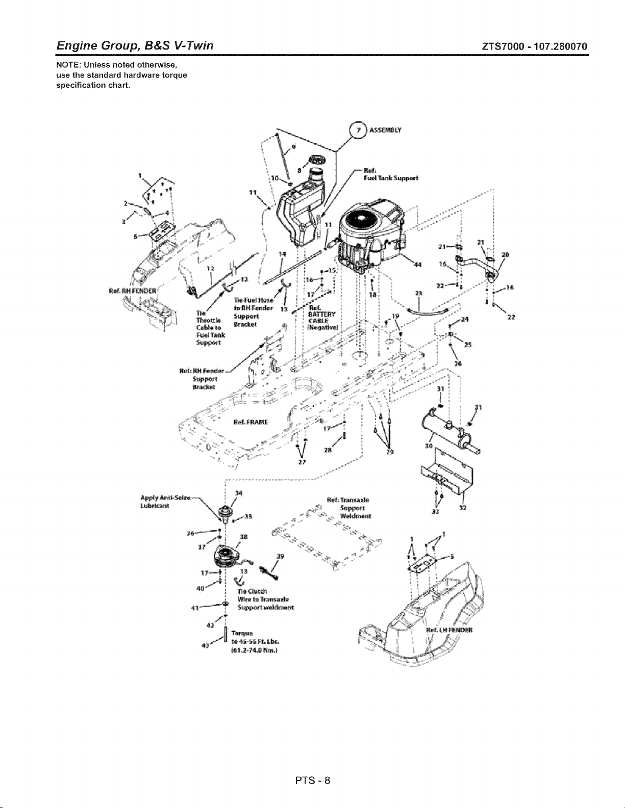
Engine Group, B&S V-Twin ZTS7000-107.280070
NOTE: Unless noted otherwise,
use the standard hardware torque
specification chart.
, "_i '> _ _
<
\
PTS - 8

Engine Group, B&S V-Twin
REF NO PART NO. QTY.
44 445877-0132-B1 1
DESCRIPTION
* ENGINE, 26 HP, B&S V-Twin
ZTS7000-107.280070
Footnotes
Note: * Purchase engine parts from engine manufacturer dealer.
PTS - 9
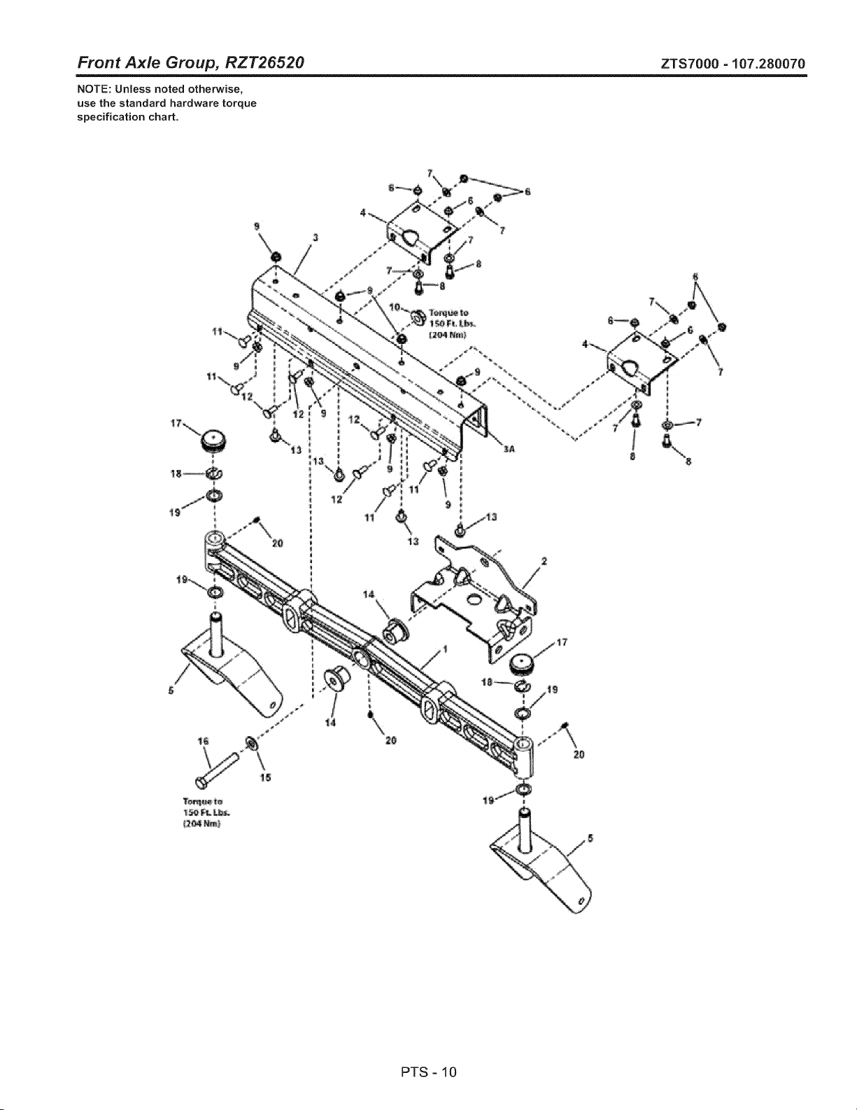
Front Axle Group, RZT26520 ZTS7000 - 107.280070
NOTE: Unless noted otherwise,
use the standard hardware torque
specification chart.
PTS - 10
Front Axle Group, RZT26520
REF NO PART NO. QTY.
1 1733426ASM 1
2 7301096BMYP 1
3 7301076BMYP 1
3A 7103773YP 2
4 7300004BMYP 2
5 1733448BMYP 2
6 7091706SM 8
7 7090188SM 8
8 7091318SM 4
9 7091601SM 8
10 1930644SM 1
11 7091508SM 4
12 1931334SM 4
13 7091811SM 4
14 7103454YP 2
15 7091587SM 1
16 7091558SM 1
17 1734135SM 2
18 1611710SM 2
19 1960160SM 4
20 7013864SM 3
ZTS7000-107.280070
DESCRiPTiON
AXLE, Front Iron Casting Machined ZT
BRACKET, Hanger, Front
BRACKET, Axle
PLATE, Friction, Adhesive Backed
BRACKET, Axle Support
WELDMENT, Caster Yoke & Spindle, Sears- Black
NUT, 5/16-18 Hex Top Lock, GR B
WASHER, 5/16" Flat
SCREW, 5/16-18 x 3/4" Hex Head Cap, GR 5, YZ
NUT, 5/16-18 Flange Lock, YZ
NUT, 1/2-13 Hex Flange Two-Way Lock Black
BOLT, 5/16-18 x 3/4" Round Head Short Square Neck, GR 5, YZ
BOLT, 5/16-18 x 7/8" Round Head Short Square Neck, GR 5, Black
BOLT, 5/16-18 x 5/8" Hex Flange lock, GR 5, YZ
BUSHING, Axle Pivot
WASHER, 1/2" Flat (SAE)
SCREW, 1/2-13 x 3-1/2" Hex Head Cap, YZ
HUB CAP, 1.481 I.D x .62 Long Red Poly
RING, Klipring External for .750 Dia. Shaft Btn
WASHER, 0.750 ID x 1.60 OD x .05 Thick, Black
LUBE FITTING, 3/16" Press Fit
Footnotes
PTS-11
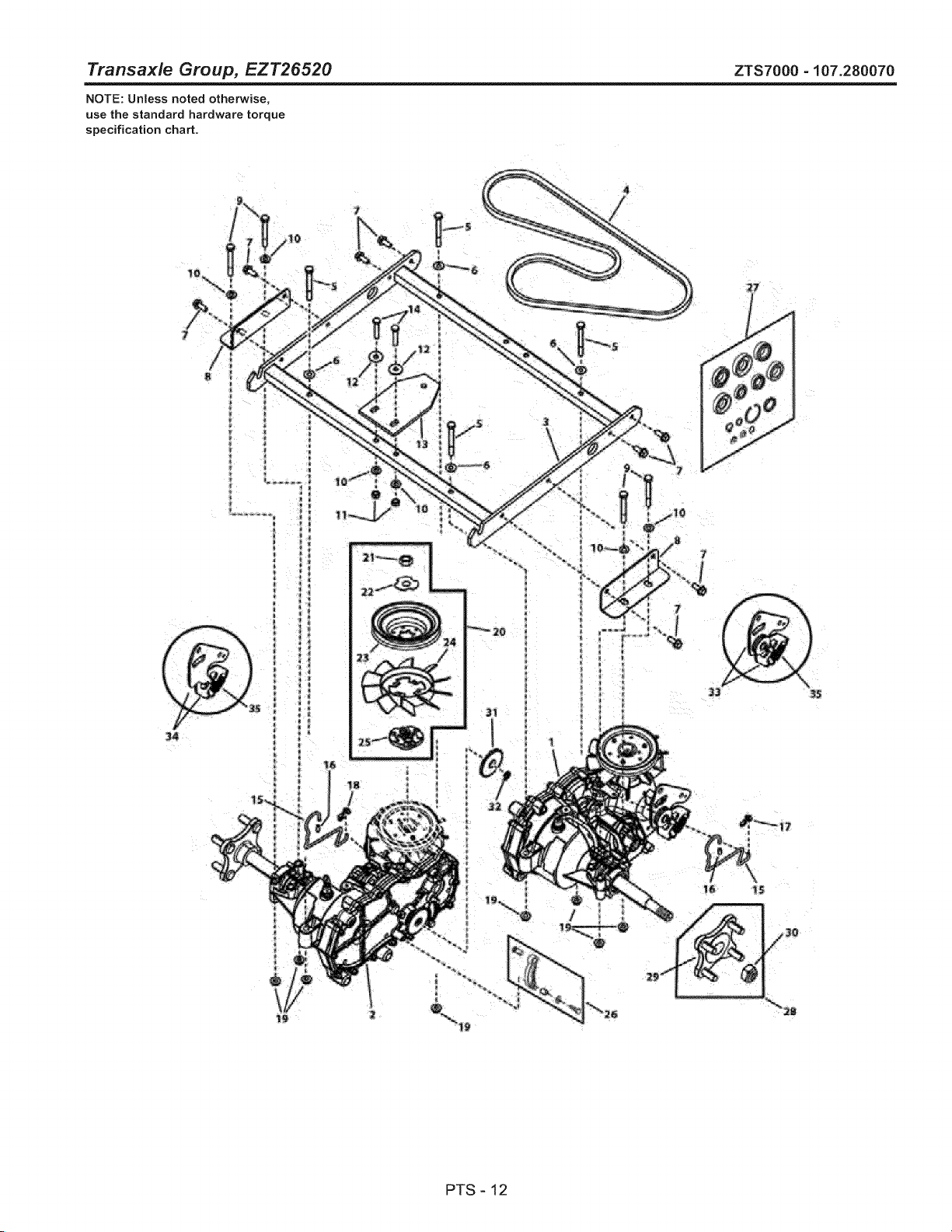
Transaxle Group, EZT26520 ZTS7000 -107.280070
NOTE: Unless noted otherwise,
use the standard hardware torque
specification chart.
34
=
Jl
_2
PTS-12

Transaxle Group, EZT26520
REF NO PART NO. QTY.
1 7104656YP 1
2 7104657YP 1
3 7400288BMYP 1
4 7100102SM 1
5 7091830SM 4
6 7015686SM 4
7 7091541SM 8
8 7300000BMYP 2
9 7091944SM 4
10 7090188SM 6
11 7091575SM 2
12 7011763SM 2
13 7101161YP 1
14 7091908YP 2
15 7103512YP 2
16 7103537YP 2
17 1725550SM 1
18 1717024SM 1
19 015X88MA 8
20 7600157YP 1
21 -- 1
22 -- 1
23 -- 2
24 -- 2
25 -- 1
26 1728075SM 1
27 1728060SM 1
28 7600158YP 2
29 -- 2
30 -- 2
31 1728076SM 1
32 1716622SM 1
33 1735490SM 1
34 1735491SM 1
35 1735482SM 2
ZTS7000 - 107.280070
DESCRIPTION
TRANSMISSION- Hydro Gear, EZT LH ZT (ZC-AUBB-2ADB-1DPX)
TRANSMISSION- Hydro Gear, EZT RH ZT (ZC-DUBB-2ADC-1DPX)
WELDMENT, Transaxle Support
V-BELT, Hydro Drive (HA Wrapped Section; 58" Effective Length)
SCREW, 5/16-18 x 3" Hex Head Cap, GR 5, YZ
SHIM WASHER, 5/16 I.D.
SCREW, 5/16-18 x 3/4" Hex Washer Self-Tap, YZ
BRACKET, Transaxle Support
SCREW, 5/16-18 x 2-3/4" Hex Head Cap, GR 5 YZ
WASHER, 5/16" Flat
NUT, 5/16-18 Hex Center Lock, YZ
FENDER WASHER, 5/16"
RUBBER, Anti-Rotation
SCREW, 5/16-18 x 1-3/4" Hex Head Cap, GR 5 YZ
ROD, Roll Release
CAP, Vinyl
CLIP, Rod End Clevis LH for .188 Dia. Rod
CLIP, Rod End Clevis RH for .188 Dia. Rod
NUT, 5/16-18 Hex Flange Center Lock
KIT, FAN & PULLEY, EZT (Includes Ref. Nos. 21, 22, 23, 24 & 25)
Nut, HEX JAM 1/2-20 (Included in Ref. No. 20)
WASHER, SLOTTED (Included in Ref. No. 20)
PULLEY, 4-1!2" Transmission (Included in Ref. No. 20)
FAN, 6" Transmission (Included in Ref. No. 20)
HUB, PULLEY 1.56 (Included in Ref. No. 20)
PARKING BRAKE ARM ASSEMBLY, Transmission
HYDRO SEAL KIT
HUB REPLACEMENT KIT (Includes Ref. Nos. 29 & 30)
HUB, EZT Transmission (Included in Ref. No. 28)
NUT, EZT Transmission (Included in Ref. No. 28)
GEAR, Parking Brake, Transmission
CLIP, E Transmission Parking Brake
ARM, Control Kit L.H.
ARM, Control Kit R.H.
SPRING, Extension
Footnotes
PTS - 13
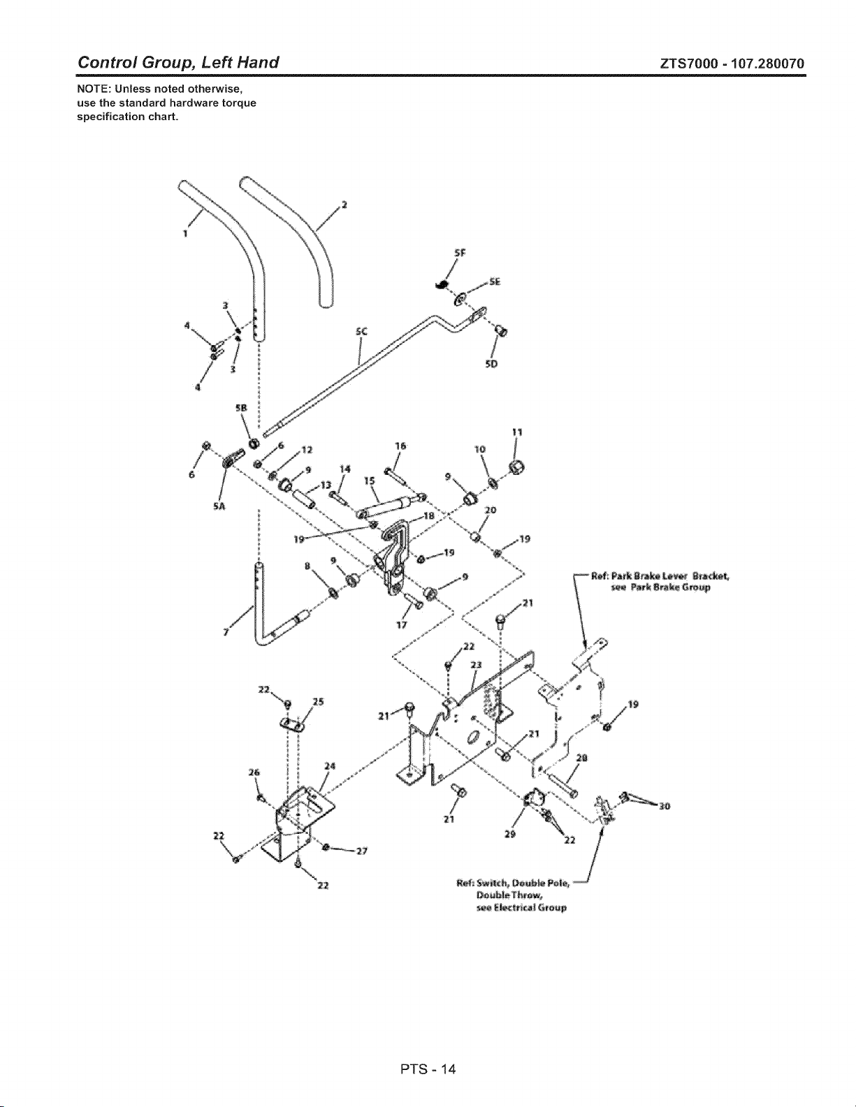
Control Group, Left Hand ZTS7000 - 107.280070
NOTE: Unless noted otherwise,
use the standard hardware torque
specification chart.
PTS - 14
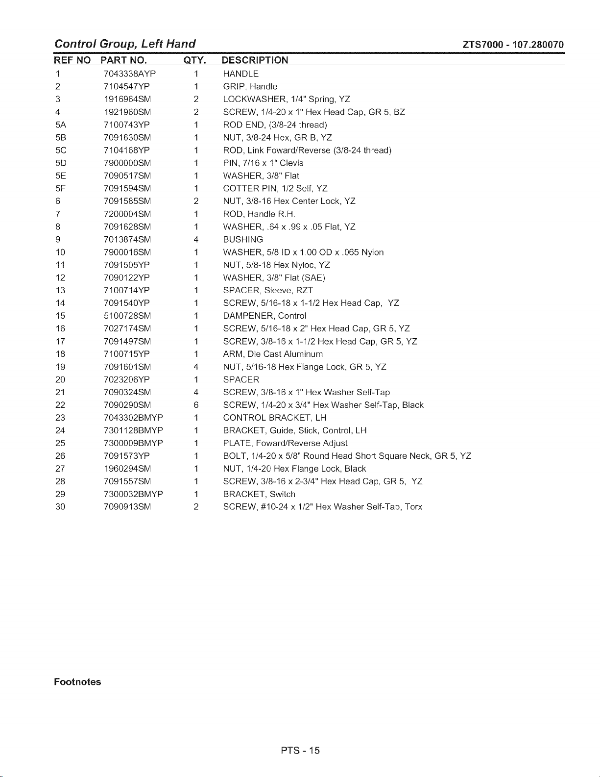
Control Group, Left Hand
REF NO PART NO. QTY.
1 7043338AYP 1
2 7104547YP 1
3 1916964SM 2
4 1921960SM 2
5A 7100743YP 1
5B 7091630SM 1
5C 7104168YP 1
5D 7900000SM 1
5E 7090517SM 1
5F 7091594SM 1
6 7091585SM 2
7 7200004SM 1
8 7091628SM 1
9 7013874SM 4
10 7900016SM 1
11 7091505YP 1
12 7090122YP 1
13 7100714YP 1
14 7091540YP 1
15 5100728SM 1
16 7027174SM 1
17 7091497SM 1
18 7100715YP 1
19 7091601SM 4
20 7023206YP 1
21 7090324SM 4
22 7090290SM 6
23 7043302BMYP 1
24 7301128BMYP 1
25 7300009BMYP 1
26 7091573YP 1
27 1960294SM 1
28 7091557SM 1
29 7300032BMYP 1
30 7090913SM 2
DESCRIPTION
HANDLE
GRIP, Handle
LOCKWASHER, 1/4" Spring, YZ
SCREW, 1/4-20 x 1" Hex Head Cap, GR 5, BZ
ROD END, (3/8-24 thread)
NUT, 3/8-24 Hex, GR B, YZ
ROD, Link Foward/Reverse (3/8-24 thread)
PIN, 7/16 x 1" Clevis
WASHER, 3/8" Flat
COTTER PIN, 1/2 Self, YZ
NUT, 3/8-16 Hex Center Lock, YZ
ROD, Handle R.H.
WASHER, .64 x .99 x .05 Flat, YZ
BUSHING
WASHER, 5/8 ID x 1.00 OD x .065 Nylon
NUT, 5/8-18 Hex Nyloc, YZ
WASHER, 3/8" Flat (SAE)
SPACER, Sleeve, RZT
SCREW, 5/16-18 x 1-1/2 Hex Head Cap, YZ
DAMPENER, Control
SCREW, 5/16-18 x 2" Hex Head Cap, GR 5, YZ
SCREW, 3/8-16 x 1-1/2 Hex Head Cap, GR 5, YZ
ARM, Die Cast Aluminum
NUT, 5/16-18 Hex Flange Lock, GR 5, YZ
SPACER
SCREW, 3/8-16 x 1" Hex Washer Self-Tap
SCREW, 1/4-20 x 3/4" Hex Washer Self-Tap, Black
CONTROL BRACKET, LH
BRACKET, Guide, Stick, Control, LH
PLATE, Foward/Reverse Adjust
ZTS7000 =107.280070
BOLT, 1/4-20 x 5/8" Round Head Short Square Neck, GR 5, YZ
NUT, 1/4-20 Hex Flange Lock, Black
SCREW, 3/8-16 x 2-3/4" Hex Head Cap, GR 5, YZ
BRACKET, Switch
SCREW, #10-24 x 1/2" Hex Washer Self-Tap, Torx
Footnotes
PTS - 15
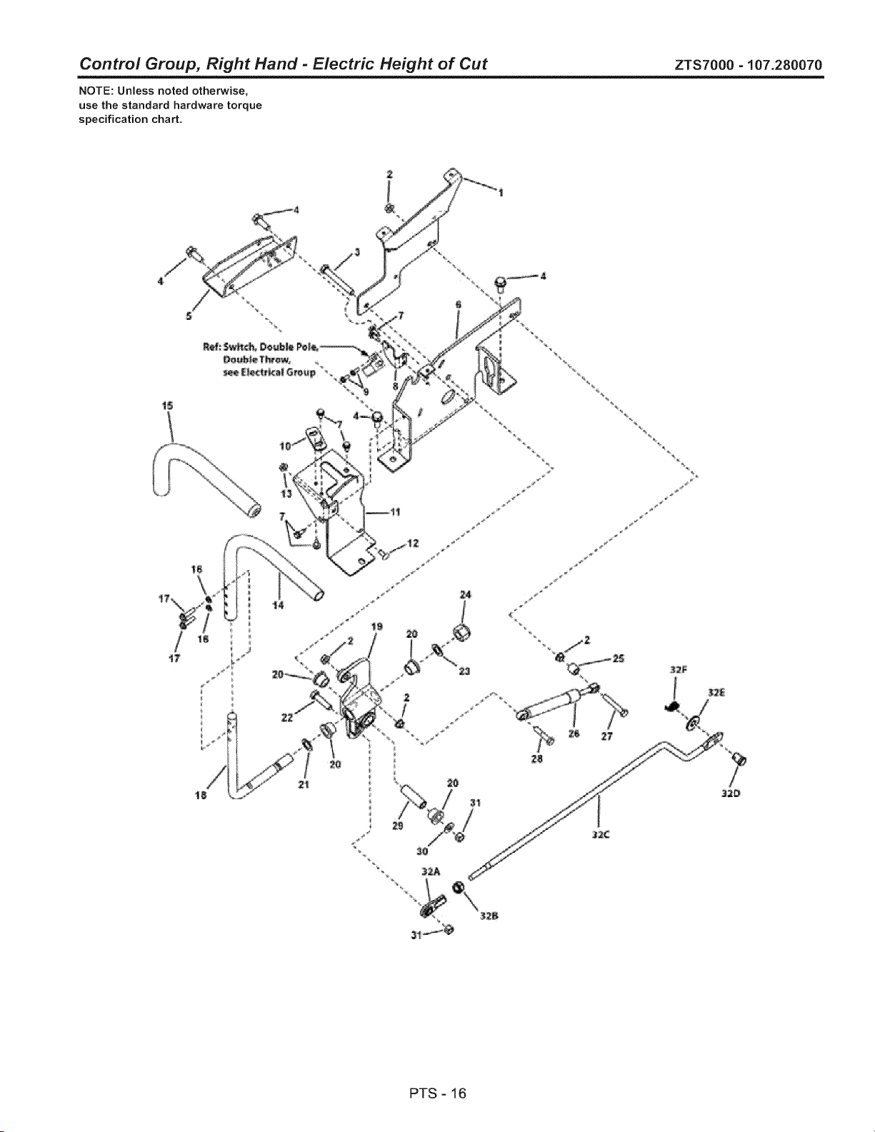
Control Group, Right Hand - Electric Height of Cut ZTS7000 - 107.280070
NOTE: Unless noted otherwise,
use the standard hardware torque
specification chart.
17 ¸
PTS - 16
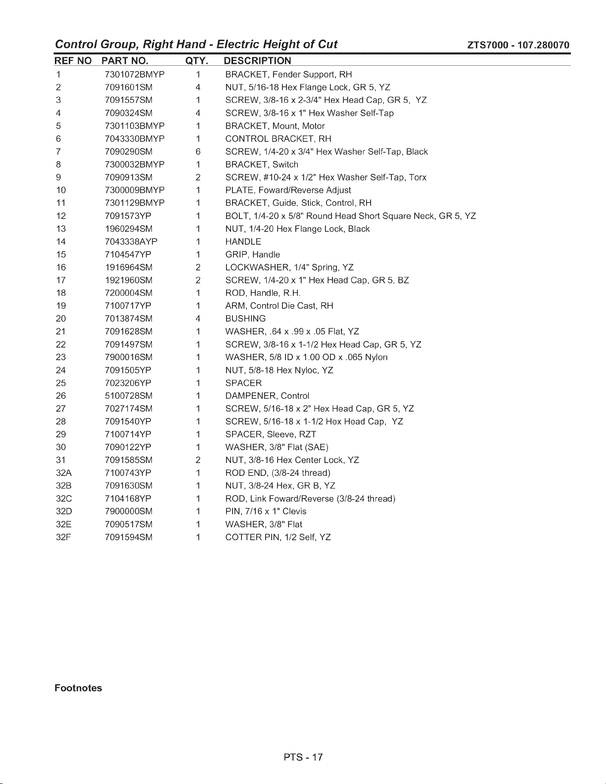
Control Group, Right Hand - Electric Height of Cut
REF NO
1
2
3
4
5
6
7
8
9
10
11
12
13
14
15
16
17
18
19
2O
21
22
23
24
25
26
27
28
29
30
31
32A
32B
32C
32D
32E
32F
ZTS7000-107.280070
PART NO.
7301072BMYP
7091601SM
7091557SM
7090324SM
7301103BMYP
7043330BMYP
7090290SM
7300032BMYP
7090913SM
7300009BMYP
7301129BMYP
7091573YP
1960294SM
7043338AYP
7104547YP
1916964SM
1921960SM
7200004SM
7100717YP
7013874SM
7091628SM
7091497SM
7900016SM
7091505YP
7023206YP
5100728SM
7027174SM
7091540YP
7100714YP
7090122YP
7091585SM
7100743YP
7091630SM
7104168YP
7900000SM
7090517SM
7091594SM
QTY.
1
4
1
4
1
1
6
1
2
1
1
1
1
1
1
2
2
1
1
4
1
1
1
1
1
1
1
1
1
1
2
1
1
1
1
1
1
DESCRiPTiON
BRACKET, Fender Support, RH
NUT, 5/16-18 Hex Flange Lock, GR 5, YZ
SCREW, 3/8-16 x 2-3/4" Hex Head Cap, GR 5, YZ
SCREW, 3/8-16 x 1" Hex Washer Self-Tap
BRACKET, Mount, Motor
CONTROL BRACKET, RH
SCREW, 1/4-20 x 3/4" Hex Washer Self-Tap, Black
BRACKET, Switch
SCREW, #10-24 x 1/2" Hex Washer Self-Tap, Torx
PLATE, Foward/Reverse Adjust
BRACKET, Guide, Stick, Control, RH
BOLT, 1/4-20 x 5/8" Round Head Short Square Neck, GR 5, YZ
NUT, 1/4-20 Hex Flange Lock, Black
HANDLE
GRIP, Handle
LOCKWASHER, 1/4" Spring, YZ
SCREW, 1/4-20 x 1" Hex Head Cap, GR 5, BZ
ROD, Handle, R.H.
ARM, Control Die Cast, RH
BUSHING
WASHER, .64 x .99 x .05 Flat, YZ
SCREW, 3/8-16 x 1-1/2 Hex Head Cap, GR 5, YZ
WASHER, 5/8 ID x 1.00 OD x .065 Nylon
NUT, 5/8-18 Hex Nyloc, YZ
SPACER
DAMPENER, Control
SCREW, 5/16-18 x 2" Hex Head Cap, GR 5, YZ
SCREW, 5/16-18 x 1-1/2 Hex Head Cap, YZ
SPACER, Sleeve, RZT
WASHER, 3/8" Flat (SAE)
NUT, 3/8-16 Hex Center Lock, YZ
ROD END, (3/8-24 thread)
NUT, 3/8-24 Hex, GR B, YZ
ROD, Link Foward/Reverse (3/8-24 thread)
PIN, 7/16 x 1" Clevis
WASHER, 3/8" Flat
COTTER PIN, 1/2 Self, YZ
Footnotes
PTS - 17
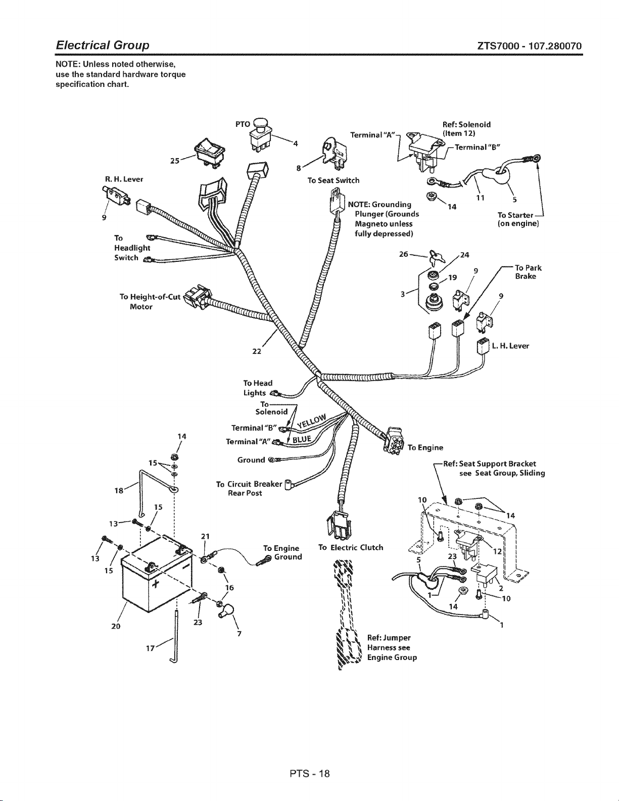
Electrical Group ZTS7000 =107.280070
NOTE: Unless noted otherwise,
use the standard hardware torque
specification chart.
R. H. Lever
9
To
Headlight
Switch
PTO
NOTE=Grounding
Plunger (Grounds
Magneto unless
fully depressed)
11
5
To Startet
(on engine}
Brake
22
L. HoLever
13
15
21
23
To Circuit Breaker
Rear Post
To Engine
Ground
\
16
/
To Electric Clutch
_ Ref: Jumper
_ Harness see
, Engine Group
ine
lO
pport Bracket
see Seat Group, Sliding
PTS - 18
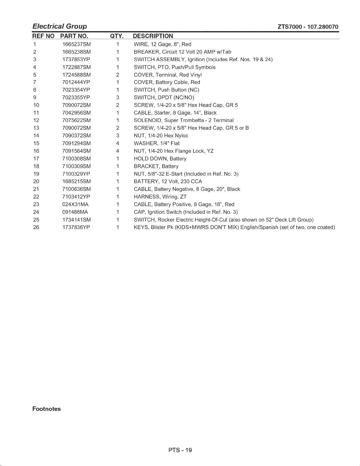
Electrical Group ZTS7000 =107.280070
REF NO PART NO.
1 1665237SM
2 1665238SM
3 1737853YP
4 1722887SM
5 1724588SM
7 7012444YP
8 7023354YP
9 7023355YP
10 7090072SM
11 7042956SM
12 7075622SM
13 7090072SM
14 7090372SM
15 7091294SM
16 7091584SM
17 7100308SM
18 7100309SM
19 7100329YP
20 1685215SM
21 7100636SM
22 7103412YP
23 024X31MA
24 091488MA
25 1734141SM
26 1737836YP
QTY.
1
1
1
1
2
1
1
3
2
1
1
2
3
4
4
1
1
1
1
1
1
1
1
1
1
DESCRIPTION
WIRE, 12 Gage, 8", Red
BREAKER, Circuit 12 Volt 20 AMP w/Tab
SWITCH ASSEMBLY, Ignition (Includes Ref. Nos. 19 & 24)
SWITCH, PTO, Push/Pull Symbols
COVER, Terminal, Red Vinyl
COVER, Battery Cable, Red
SWITCH, Push Button (NC)
SWITCH, DPDT (NC/NO)
SCREW, 1/4-20 x 5/8" Hex Head Cap, GR 5
CABLE, Starter, 8 Gage, 14", Black
SOLENOID, Super Trombetta - 2 Terminal
SCREW, 1/4-20 x 5/8" Hex Head Cap, GR 5 or B
NUT, 1/4-20 Hex Nyloc
WASHER, 1/4" Flat
NUT, 1/4-20 Hex Flange Lock, YZ
HOLD DOWN, Battery
BRACKET, Battery
NUT, 5/8"-32 E-Start (Included in Ref. No. 3)
BATTERY, 12 Volt, 230 CCA
CABLE, Battery Negative, 8 Gage, 20", Black
HARNESS, Wiring, ZT
CABLE, Battery Positive, 8 Gage, 18", Red
CAP, Ignition Switch (Included in Ref. No. 3)
SWITCH, Rocker Electric Height-Of-Cut (also shown on 52" Deck Lift Group)
KEYS, Blister Pk (KIDS÷MWRS DON'T MIX) English/Spanish (set of two, one coated)
Footnotes
PTS - 19
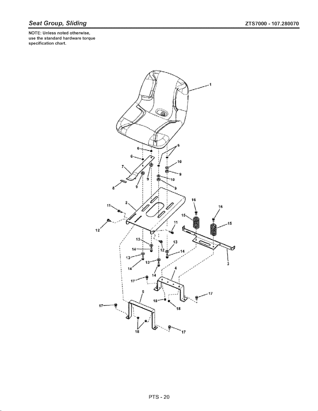
Seat Group, Sliding ZTS7000 - 107.280070
NOTE: Unless noted otherwise,
use the standard hardware torque
specification chart.
z
_2
li 6i
PTS - 20
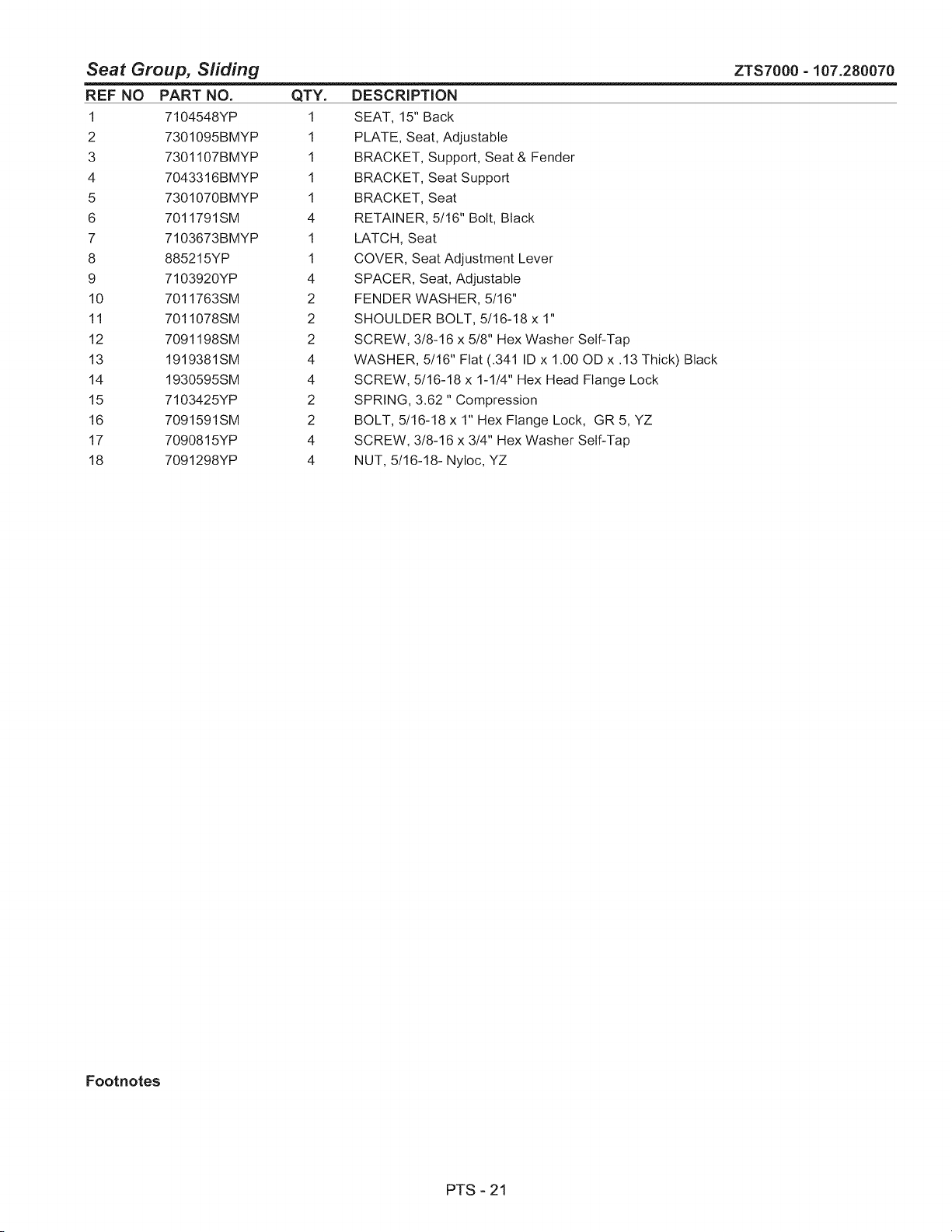
Seat Group, Sliding
REF NO PART NO. QTY.
1 7104548YP 1
2 7301095BMYP 1
3 7301107BMYP 1
4 7043316BMYP 1
5 7301070BMYP 1
6 7011791SM 4
7 7103673BMYP 1
8 885215YP 1
9 7103920YP 4
10 7011763SM 2
11 7011078SM 2
12 7091198SM 2
13 1919381SM 4
14 1930595SM 4
15 7103425YP 2
16 7091591SM 2
17 7090815YP 4
18 7091298YP 4
DESCRiPTiON
SEAT, 15" Back
PLATE, Seat, Adjustable
BRACKET, Support, Seat & Fender
BRACKET, Seat Support
BRACKET, Seat
RETAINER, 5/16" Bolt, Black
LATCH, Seat
COVER, Seat Adjustment Lever
SPACER, Seat, Adjustable
FENDER WASHER, 5/16"
SHOULDER BOLT, 5/16-18 x 1"
SCREW, 3/8-16 x 5/8" Hex Washer Self-Tap
WASHER, 5/16" Flat (.341 ID x 1.00 OD x .13 Thick) Black
SCREW, 5/16-18 x 1-1/4" Hex Head Flange Lock
SPRING, 3.62 " Compression
BOLT, 5/16-18 x 1" Hex Flange Lock, GR 5, YZ
SCREW, 3/8-16 x 3/4" Hex Washer Self-Tap
NUT, 5/16-18- Nyloc, YZ
ZTS7000-107.280070
Footnotes
PTS - 21
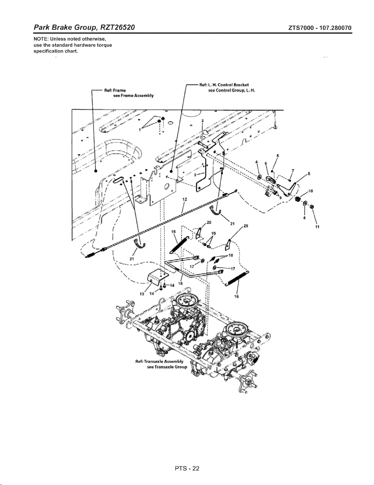
Park Brake Group, RZT26520 ZTS7000 - 107.280070
NOTE: Unless noted otherwise,
use the standard hardware torque
specification chart.
i
\
\
\
PTS - 22
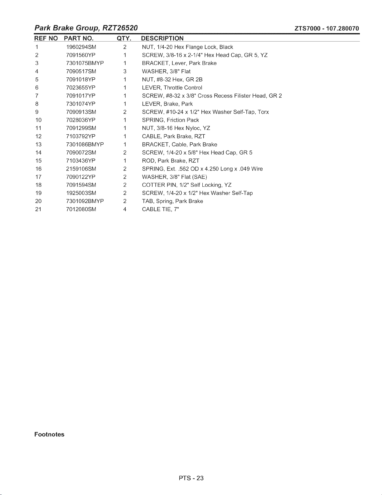
Park Brake Group, RZT26520
REF NO PART NO. QTY.
1 1960294SM 2
2 7091560YP 1
3 7301075BMYP 1
4 7090517SM 3
5 7091018YP 1
6 7023655YP 1
7 7091017YP 1
8 7301074YP 1
9 7090913SM 2
10 7028036YP 1
11 7091299SM 1
12 7103792YP 1
13 7301086BMYP 1
14 7090072SM 2
15 7103436YP 1
16 2159106SM 2
17 7090122YP 2
18 7091594SM 2
19 1925003SM 2
20 7301092BMYP 2
21 7012080SM 4
DESCRIPTION
NUT, 1/4-20 Hex Flange Lock, Black
SCREW, 3/8-16 x 2-1/4" Hex Head Cap, GR 5, YZ
BRACKET, Lever, Park Brake
WASHER, 3/8" Flat
NUT, #8-32 Hex, GR 2B
LEVER, Throttle Control
SCREW, #8-32 x 3/8" Cross Recess Filister Head, GR 2
LEVER, Brake, Park
SCREW, #10-24 x 1/2" Hex Washer Self-Tap, Torx
SPRING, Friction Pack
NUT, 3/8-16 Hex Nyloc, YZ
CABLE, Park Brake, RZT
BRACKET, Cable, Park Brake
SCREW, 1/4-20 x 5/8" Hex Head Cap, GR 5
ROD, Park Brake, RZT
SPRING, Ext..562 OD x 4.250 Long x .049 Wire
WASHER, 3/8" Flat (SAE)
COTTER PIN, 1/2" Self Locking, YZ
SCREW, 1/4-20 x 1/2" Hex Washer Self-Tap
TAB, Spring, Park Brake
CABLE TIE, 7"
ZTS7000-107.280070
Footnotes
PTS-23

52" Deck Lift Group - Electric Height of Cut ZTS7000 - 107.280070
NOTE: Unless noted otherwise,
use the standard hardware torque
specification chart.
\
\
PTS - 24

52" Deck Lift Group - Electric
REF NO PART NO. QTY.
1 7091304SM 4
2 7301104BMYP 1
3 7103956YP 1
4 7091584SM 1
5 7301105BMYP 1
6 7091619SM 4
7 009X54MA 1
8 7090122YP 2
9 7091503SM 7
10 7090072SM 2
11 7091603SM 4
12 578309MA 1
13 7301119BCYP 1
14 7023649YP 1
15 7301120BMYP 1
16 164X34MA 1
17 7090673SM 1
18 7400011BMYP 1
19 7026196SM 1
20 7301125BMYP 1
21 7091495SM 2
22 1668344SM 1
23 7103818YP 1
24 1734217SM 2
25 1916950SM 2
26 1731894SM 2
27 1666294SM 2
28 1960687SM 2
29 094067MA 2
30 7301098BMYP 2
31 015Xg8MA 4
32 1732129SM 2
33 7091601SM 4
34 7300028BMYP 2
35 7091811SM 4
36 1960170SM 4
37 1736081YP 2
38 1913744SM 2
39 1737417YP 2
40 1960379SM 2
41 1930644SM 2
42 7301097BMYP 1
43 1734141SM 1
Height of Cut
DESCRIPTION
SCREW, 3/8-16 x 1" Hex Head Cap, GR 5, YZ
BRACKET, Lift, Deck, Primary
ROD, Indicator, Height-Of-Cut
NUT, 1/4-20 Hex Flange Lock, GR 5, YZ
BRACKET, Lift, Deck, Secondary
NUT, 3/8-16 Hex Flange lock, YZ
SHOULDER BOLT, 1/4-20 x 3/8"
WASHER, 3/8" Flat (SAE)
HAIR PIN, 3/32 x 1-1/2" YZ
SCREW, 1/4-20 x 5/8" Hex Head Cap, GR 5
NUT, 1/4-20 Hex Nytoc, YZ
CLEVIS PIN, .25 x 1.09
LEVER, Indicator, Height-Of-Cut
WASHER, 5/16" Nylon
BRACKET, Indicator, Height-Of-Cut
SPRING, Compression
COTTER PIN, .06 x 1/2" YZ
WELDMENT, Deck Lift, 38/42
BEARING, Flange, .75 ID PM
SPACER, Bearing, .25"
SCREW, 1/4-20 x 3/4" Hex Head Cap, GR 5 YZ
SHEAR PIN, .248 ID x 1-3/4" Long
MOTOR, Actuator, Lift, Deck
ROD, Mower Lift (3/8-16 thread) Yellow
NUT, 3/8-16 Hex, Black
TRUNNION, Powdered Metal, Yellow, Regent
SPACER, .385 ID x .6697 OD x .455 Long, PM Yellow
NUT, 3/8-16 Hex Flange Esna, Black
PIN, 3/8-16 Threaded Shoulder
BAR, Rear Lift
NUT, 3/8-16 Hex Flange Center Lock, Zinc Plated
SHOULDER BOLT, 3/8-16 x .94, BZ
NUT, 5/16-18 Flange Lock, YZ
BRACKET, Deck Hanger
BOLT, 5/16-18 x 5/8" Hex Flange lock, GR 5, YZ
WASHER, 1/2" Flat (0.51 ID x 1.00 OD x .10 Thick) Black
ROD, Front Bail (1/2-13 thread) MWR
NUT, 1/2-13 Hex Jam, Black
TRUNNION, Unthreaded
NUT, 1/2-13 Jam, Esna Light Thin
NUT, 1/2-13 Hex Flange Two-Way Lock Black
SUPPORT, Hanger
SWITCH, Rocker Electric Height-Of-Cut
ZTS7000-107.280070
Footnotes
PTS-25
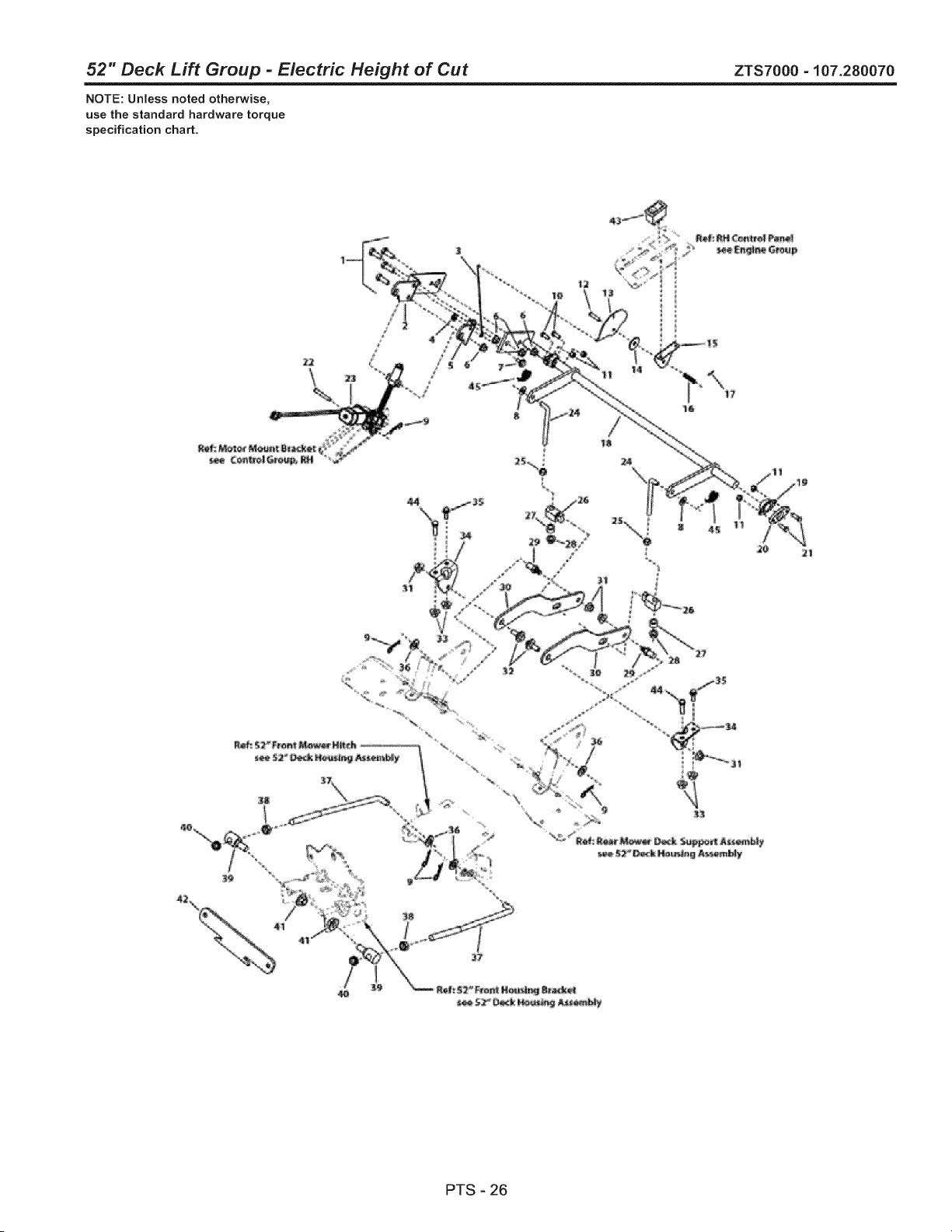
52" Deck Lift Group - Electric Height of Cut ZTS7000 - 107.280070
NOTE: Unless noted otherwise,
use the standard hardware torque
specification chart.
\
\
PTS - 26

52" Deck Lift Group - Electric Height of Cut
REF NO PART NO. QTY. DESCRIPTION
44 7027168SM 2 CAPSCREW, Hex Head, 5/16-18 x 1
45 7091593SM 2 COTTER PIN, 3/8" Self Lock
ZTS7000-107.280070
Footnotes
PTS-27
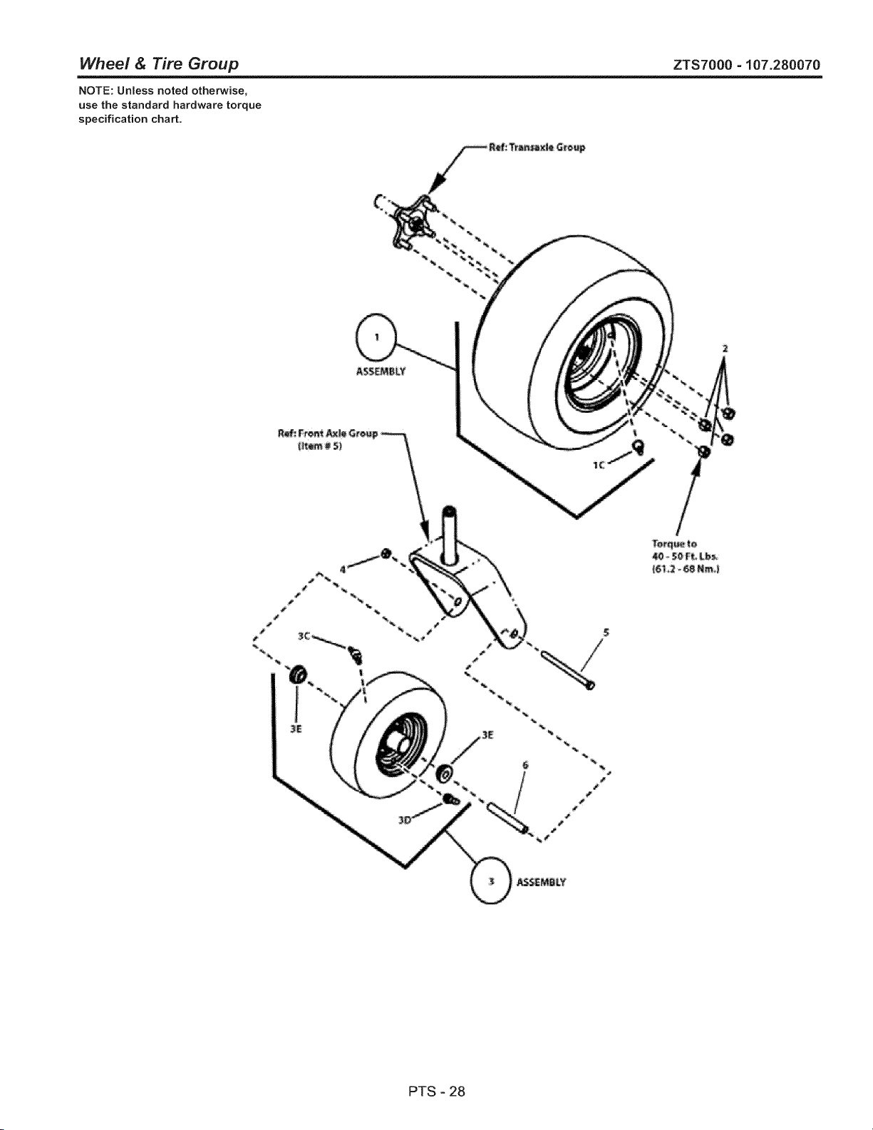
Wheel & Tire Group ZTS7000 - 107.280070
NOTE: Unless noted otherwise,
use the standard hardware torque
specification chart.
%
PTS - 28

Wheel & Tire Group
REF NO PART NO. QTY.
1 7103403YP 2
1C 7012234SM 1
2 7027192SM 8
3 1734013SM 2
3C 7104428YP 1
3D 2172353SM 1
3E 1739281YP 2
4 7090839SM 2
5 7091772SM 2
6 1734841SM 2
ZTS7000 - 107.280070
DESCRIPTION
ASSEMBLY, Tire & Wheel (Rim) (Incl. Ref. 1C)
AIR VALVE STEM, Snap-In (Included with Ref. 1)
LUG NUT, 1/2 - 20 Tapered Seat, YZ
ASSEMBLY, Wheel & Tire Sears ZTS 11 x 4-5 (Incl. Ref. 3C, 3D, 3E)
GREASE FITTING, (8M x 1 threads, 45 degree) (included with Ref. 3)
VALVE, Air (Included with Ref. 3)
BUSHING, 0.6321D 1.377OD, .62 (Included with Ref. 3)
NUT, 7/16-14 Hex Center Lock, GR 5 or B
SCREW, 7/16-14NC x 6", Flex Head Cap, GR 5, YZ
TUBE, Caster Wheel, 0.625 OD 4.53 OLG 0.625 OD
Footnotes
PTS - 29
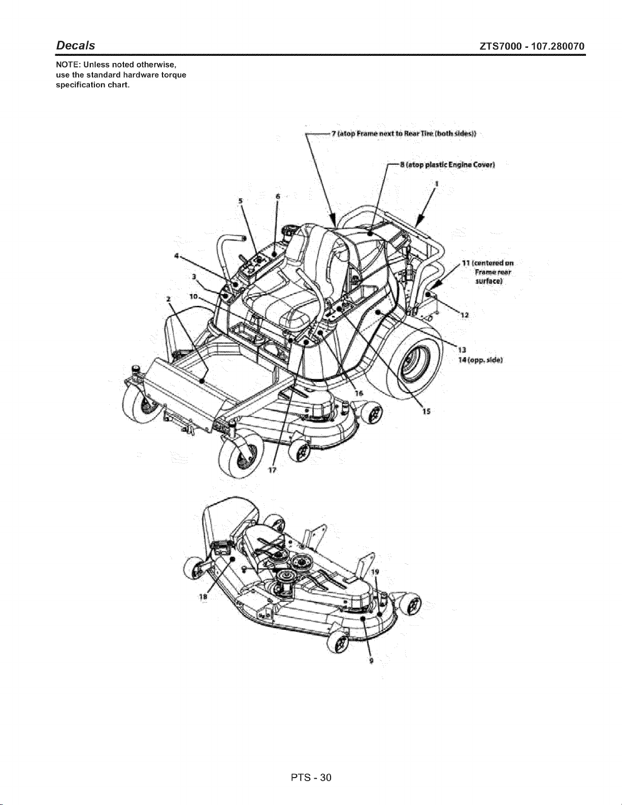
Deca/s ZTS7000 - 107.280070
NOTE: Unless noted otherwise,
use the standard hardware torque
specification chart.
PTS - 30

Decals
REF NO
1
2
3
4
5
6
7
8
9
10
11
12
13
14
15
16
17
18
19
2O
21
22
PART NO.
7103145YP
7104234YP
7104227YP
7104225YP
7104233YP
7104224YP
7104231YP
7104393YP
7103181YP
7104117YP
7101940YP
1734273SM
7104114YP
7104116YP
7104232YP
7104223YP
7104226YP
1704277SM
1704276SM
7104502YP
7104553YP
7104554YP
QTY.
1
1
1
1
1
1
2
1
1
1
1
1
1
1
1
1
1
1
1
1
1
1
DESCRiPTiON
DECAL
DECAL
DECAL
DECAL
DECAL
DECAL
DECAL
DECAL
DECAL
DECAL
DECAL
DECAL
DECAL
DECAL
DECAL
DECAL
DECAL
DECAL
DECAL
DECAL
DECAL
DECAL
Rear, Craftsman ZTS
Instructional, 285Z
Handle, Ground Speed, RH, 285Z
Safety, Symbol, 285Z
Control Panel, RH 285Z
DANGER, English, 285Z
Release, Transaxle, 285Z
Caution, Screen Rotating
52" Deck
Model, Craftsman ZTS
Weight Limitation
Warning Burn Hazard
LH Fender, Craftsman ZTS
RH Fender, Craftsman ZTS
Control Panel, LH 285Z
WARNING, English, 285Z
Handle, Ground Speed, LH, 285Z
DANGER Do Not Operate w/o Deflector
DANGER Do Not Put Hand/Feet in Mower
Parts, Craftsman
Craftsman Stripe LH
Craftsman Stripe RH
ZTS7000-107.280070
Footnotes
PTS - 31
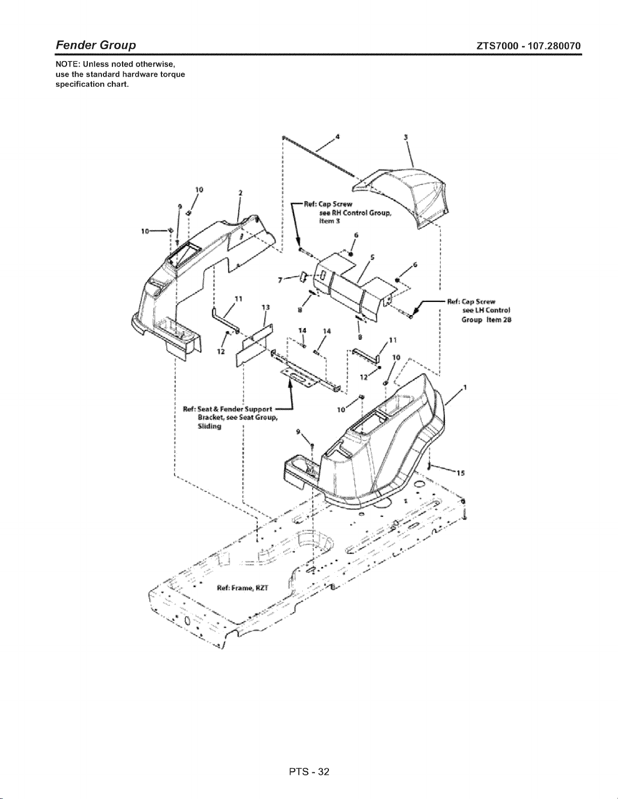
Fender Group ZTS7000 - 107.280070
NOTE: Unless noted otherwise,
use the standard hardware torque
specification chart.
tO 2
_4
PTS - 32

Fender Group ZTS7000 - 107.280070
REF NO PART NO.
1 7103776YP
2 7103775YP
3 7103777YP
4 7103998YP
5 7301161BZYP
6 1960687SM
7 1722611SM
8 7104514YP
9 7091246YP
10 7023295SM
11 7301101BMYP
12 7091298YP
13 7301126BMYP
14 7027168SM
15 7091503SM
QTY.
1
1
1
1
1
2
1
2
2
4
2
2
1
2
1
DESCRIPTION
FENDER, LH
FENDER, RH
COVER, Engine
ROD, Pivot, Hood
COVER, BATTERY, 285z
NUT, Hex Flange ESNA, 3/8-16
PLUG, Hole
STRIP, TRIM
SCREW, 1/4-20 x 3/4" Pan Head Self-Tap (Torx)
U-NUT, 1!4-20
BRACKET, Support, Fender
NUT, 5/16-18 3B Nyloc, YZ
PLATE, Side, RH
SCREW, 5/16-18 x 1" Hex Head Cap, GR 5, YZ
HAIR PIN, 3/32 x 1-1/2", YZ
Footnotes
PTS - 33
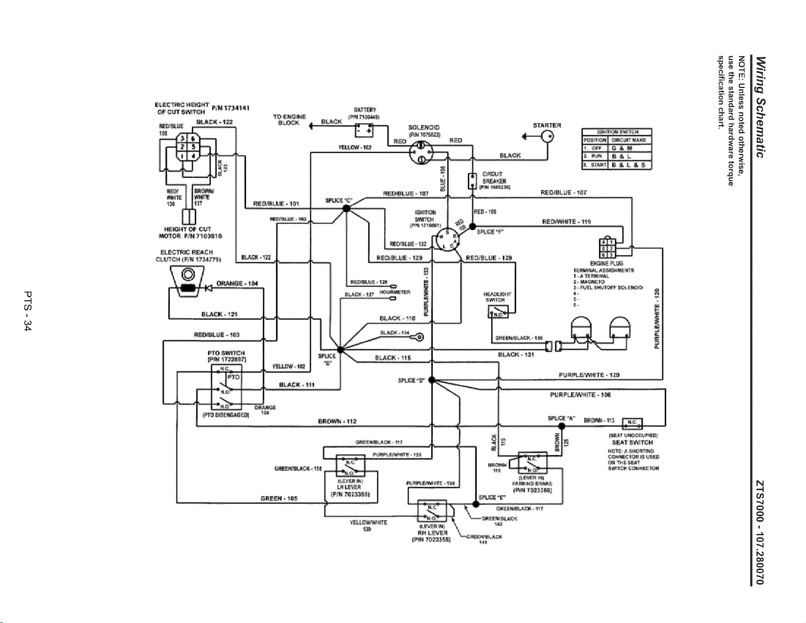
'13
-4
03
!
03
4_
"4
"4
",4

Wiring Schematic
REF NO PART NO.
1 7103412YP
QTY.
1
DESCRIPTION
HARNESS, Wiring
ZTS7000-107.280070
Footnotes
PTS-35
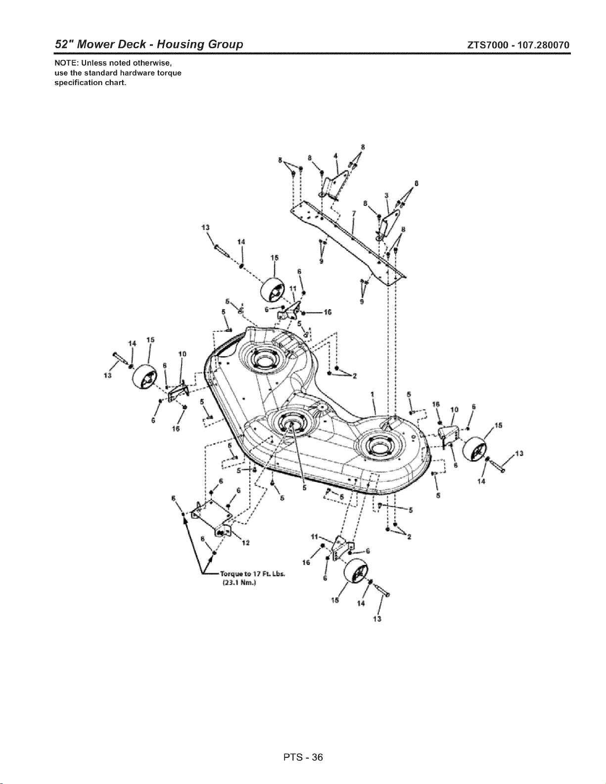
52" Mower Deck - Housing Group ZTS7000 - 107.280070
NOTE: Unless noted otherwise,
use the standard hardware torque
specification chart.
°i
PTS - 36
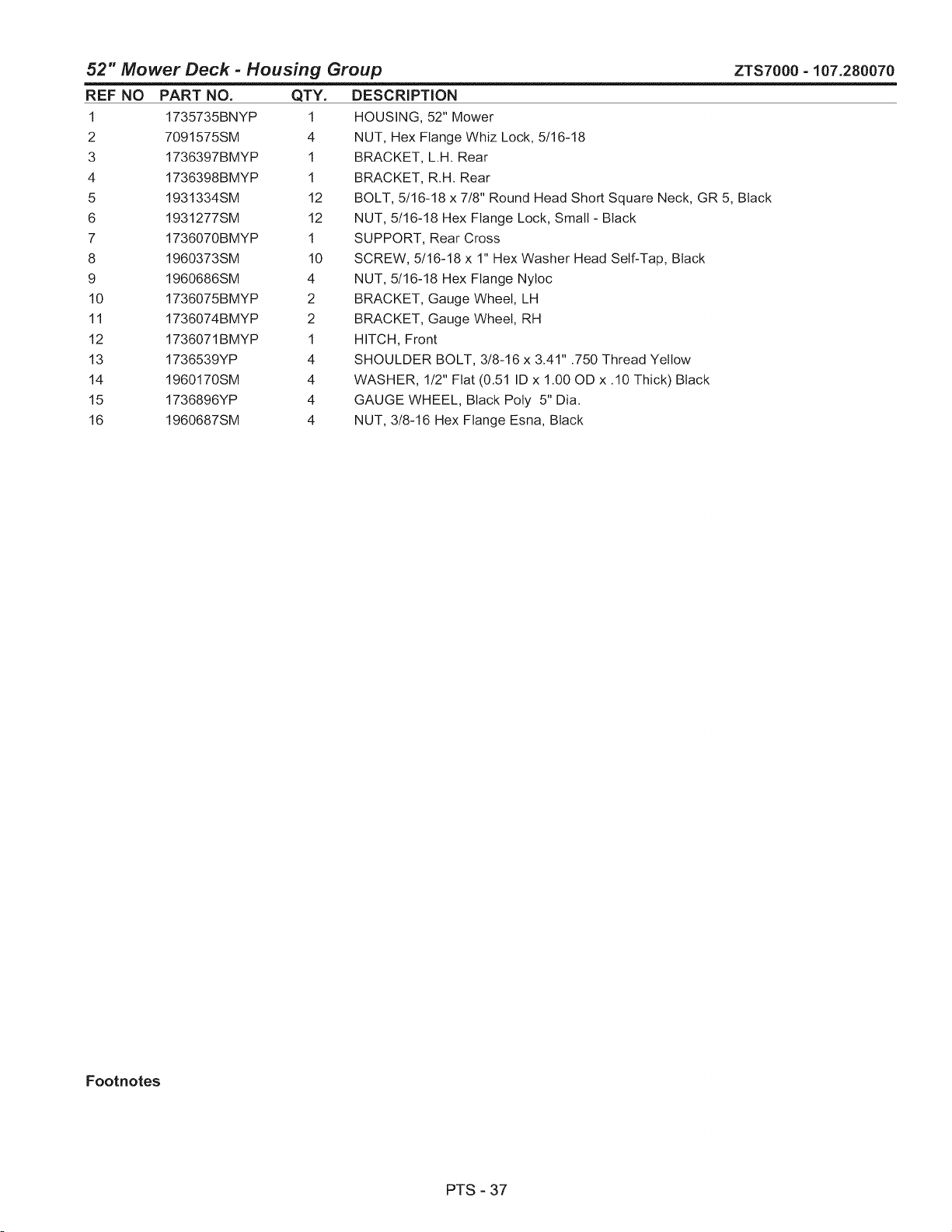
52" Mower Deck - Housing Group
REF NO
1
2
3
4
5
6
7
8
9
10
11
12
13
14
15
16
ZTS7000-107.280070
PART NO.
1735735BNYP
7091575SM
1736397BMYP
1736398BMYP
1931334SM
1931277SM
1736070BMYP
1960373SM
1960686SM
1736075BMYP
1736074BMYP
1736071BMYP
1736539YP
1960170SM
1736896YP
1960687SM
QTY.
1
4
1
1
12
12
1
10
4
2
2
1
4
4
4
4
DESCRIPTION
HOUSING, 52" Mower
NUT, Hex Flange Whiz Lock, 5/16-18
BRACKET, L.H. Rear
BRACKET, R.H. Rear
BOLT, 5/16-18 x 7/8" Round Head Short Square Neck, GR 5, Black
NUT, 5/16-18 Hex Flange Lock, Small- Black
SUPPORT, Rear Cross
SCREW, 5/16-18 x 1" Hex Washer Head Self-Tap, Black
NUT, 5/16-18 Hex Flange Nyloc
BRACKET, Gauge Wheel, LH
BRACKET, Gauge Wheel, RH
HITCH, Front
SHOULDER BOLT, 3/8-16 x 3.41" .750 Thread Yellow
WASHER, 1/2" Flat (0.51 ID x 1.00 OD x .10 Thick) Black
GAUGE WHEEL, Black Poty 5" Dia.
NUT, 3/8-16 Hex Flange Esna, Black
Footnotes
PTS - 37
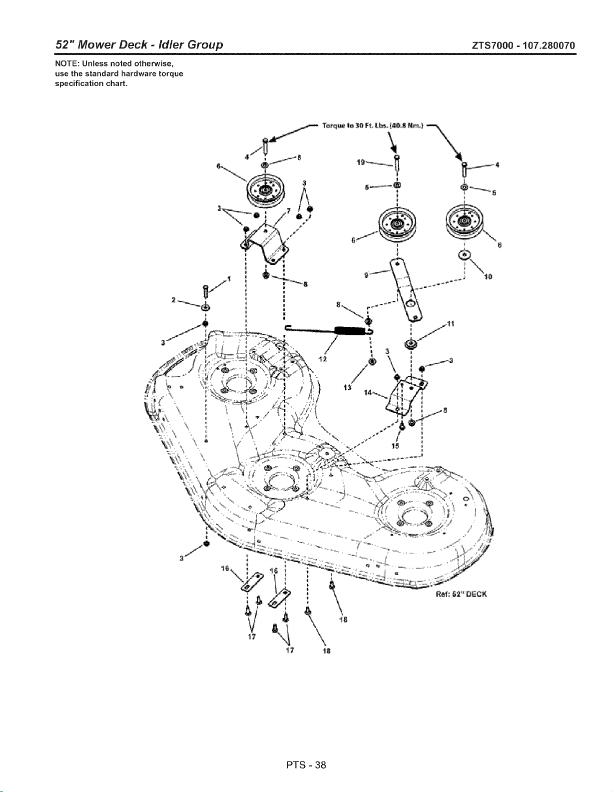
52" Mower Deck - idler Group ZTS7000 - 107.280070
NOTE: Unless noted otherwise,
use the standard hardware torque
specification chart.
PTS - 38
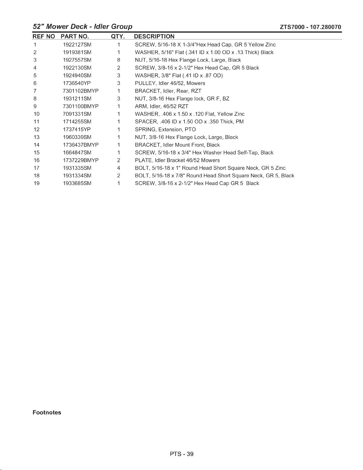
52" Mower Deck - idler Group
REF NO PART NO. QTY.
1 1922127SM 1
2 1919381SM 1
3 1927557SM 8
4 1922130SM 2
5 1924940SM 3
6 1736540YP 3
7 7301102BMYP 1
8 1931211SM 3
9 7301100BMYP 1
10 7091331SM 1
11 1714255SM 1
12 1737415YP 1
13 1960339SM 1
14 1736437BMYP 1
15 1664847SM 1
16 1737229BMYP 2
17 1931335SM 4
18 1931334SM 2
19 1933685SM 1
ZTS7000-107.280070
DESCRiPTiON
SCREW, 5/16-18 X 1-3/4"Hex Head Cap, GR 5 Yellow Zinc
WASHER, 5/16" Flat (.341 ID x 1.00 OD x .13 Thick) Black
NUT, 5/16-18 Hex Flange Lock, Large, Black
SCREW, 3/8-16 x 2-1/2" Hex Head Cap, GR 5 Black
WASHER, 3/8" Flat (.41 ID x .87 OD)
PULLEY, Idler 46/52, Mowers
BRACKET, Idler, Rear, RZT
NUT, 3/8-16 Hex Flange lock, GR F, BZ
ARM, Idler, 46/52 RZT
WASHER, .406 x 1.50 x .120 Flat, Yellow Zinc
SPACER, .406 ID x 1.50 OD x .350 Thick, PM
SPRING, Extension, PTO
NUT, 3/8-16 Hex Flange Lock, Large, Black
BRACKET, Idler Mount Front, Black
SCREW, 5/16-18 x 3!4" Hex Washer Head Self-Tap, Black
PLATE, Idler Bracket 46/52 Mowers
BOLT, 5/16-18 x 1" Round Head Short Square Neck, GR 5 Zinc
BOLT, 5/16-18 x 7/8" Round Head Short Square Neck, GR 5, Black
SCREW, 3/8-16 x 2-1/2" Hex Head Cap GR 5 Black
Footnotes
PTS-39
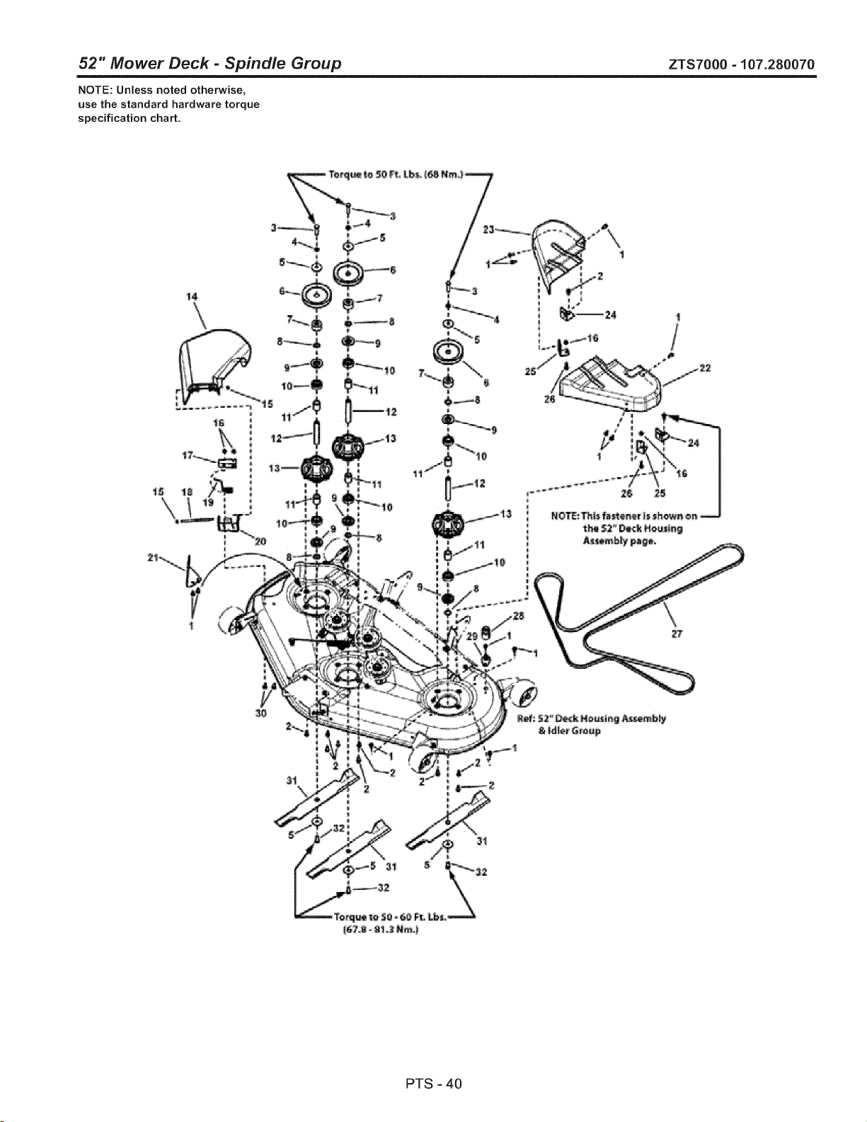
52" Mower Deck - Spindle Group ZTS7000 - 107.280070
NOTE: Unless noted otherwise,
use the standard hardware torque
specification chart.
t4
PTS-40
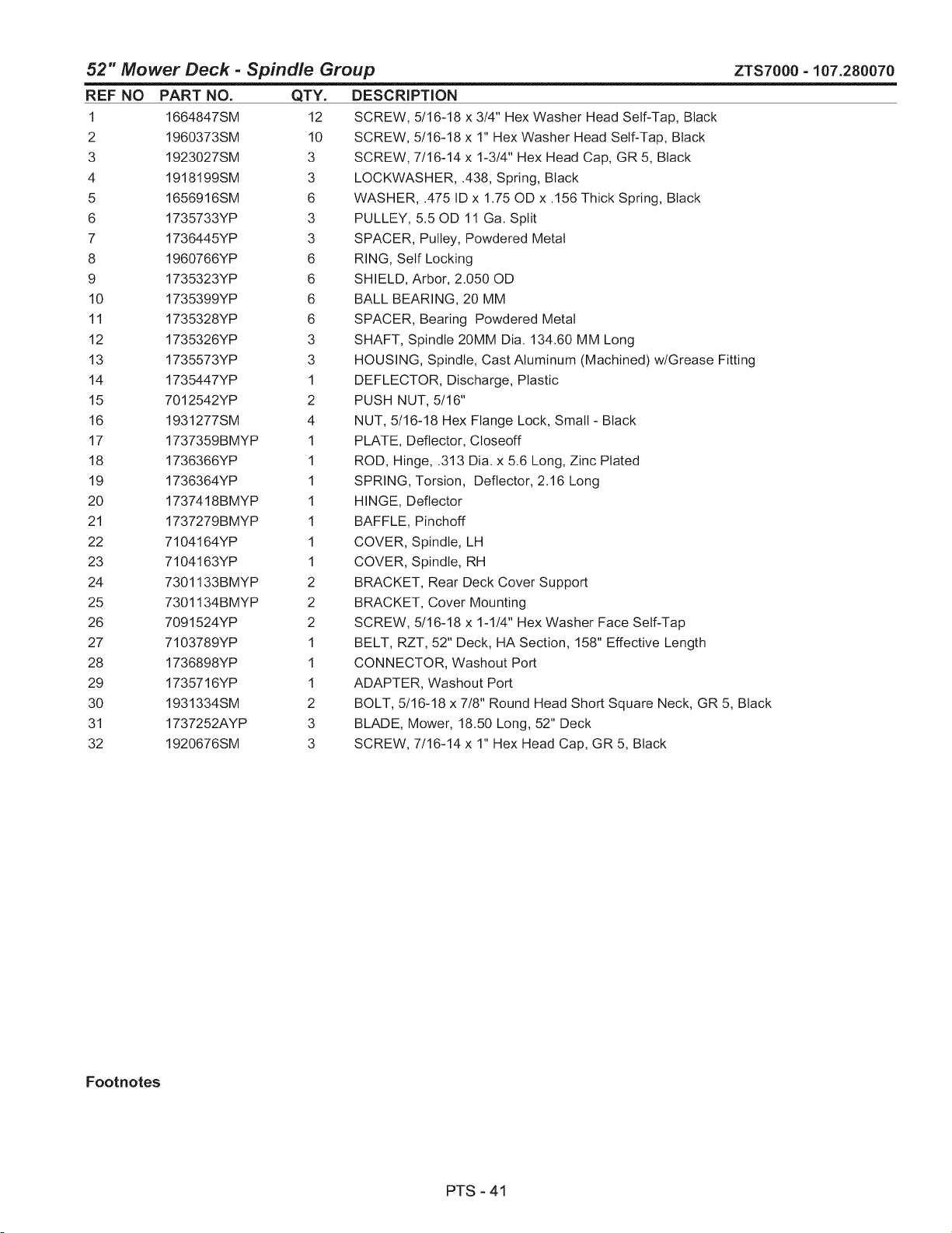
52" Mower Deck - Spindle Group ZTS7000 - 107.280070
REF NO PART NO. QTY.
1 1664847SM 12
2 1960373SM 10
3 1923027SM 3
4 1918199SM 3
5 1656916SM 6
6 1735733YP 3
7 1736445YP 3
8 1960766YP 6
9 1735323YP 6
10 1735399YP 6
11 1735328YP 6
12 1735326YP 3
13 1735573YP 3
14 1735447YP 1
15 7012542YP 2
16 1931277SM 4
17 1737359BMYP 1
18 1736366YP 1
19 1736364YP 1
20 1737418BMYP 1
21 1737279BMYP 1
22 7104164YP 1
23 7104163YP 1
24 7301133BMYP 2
25 7301134BMYP 2
26 7091524YP 2
27 7103789YP 1
28 1736898YP 1
29 1735716YP 1
30 1931334SM 2
31 1737252AYP 3
32 1920676SM 3
DESCRiPTiON
SCREW, 5/16-18 x 3/4" Hex Washer Head Self-Tap, Black
SCREW, 5/16-18 x 1" Hex Washer Head Self-Tap, Black
SCREW, 7/16-14 x 1-3/4" Hex Head Cap, GR 5, Black
LOCKWASHER, .438, Spring, Black
WASHER, .475 ID x 1.75 OD x .156 Thick Spring, Black
PULLEY, 5.50D 11 Ga. Split
SPACER, Pulley, Powdered Metal
RING, Self Locking
SHIELD, Arbor, 2.050 OD
BALL BEARING, 20 MM
SPACER, Bearing Powdered Metal
SHAFT, Spindle 20MM Dia. 134.60 MM Long
HOUSING, Spindle, Cast Aluminum (Machined) w/Grease Fitting
DEFLECTOR, Discharge, Plastic
PUSH NUT, 5/16"
NUT, 5/16-18 Hex Flange Lock, Small- Black
PLATE, Deflector, Closeoff
ROD, Hinge, .313 Dia. x 5.6 Long, Zinc Plated
SPRING, Torsion, Deflector, 2.16 Long
HINGE, Deflector
BAFFLE, Pinchoff
COVER, Spindle, LH
COVER, Spindle, RH
BRACKET, Rear Deck Cover Support
BRACKET, Cover Mounting
SCREW, 5/16-18 x 1-1/4" Hex Washer Face Self-Tap
BELT, RZT, 52" Deck, HA Section, 158" Effective Length
CONNECTOR, Washout Port
ADAPTER, Washout Port
BOLT, 5/16-18 x 7/8" Round Head Short Square Neck, GR 5, Black
BLADE, Mower, 18.50 Long, 52" Deck
SCREW, 7/16-14 x 1" Hex Head Cap, GR 5, Black
Footnotes
PTS - 41

48 SHORT BLOCK
445877-0132-B1
I 1058 OPERATOR'S MANUAL I
1329 REPLACMENT ENGINE
1330 REPAIR MANUAL
85O
10
11_)
252
3
718 _:_
" _' 562 \
212
'" J278 _'_
505 _!:_)
i
i
i
,i
_]i_ 524
15
s
552 _:.>_
552A
742 _:
404 _-._
_'- <' r //_,,.I
_ _ ',L ...... /_ '_b_ 1013
" _/!W
q 20
75O
m
A
1027
220 _ ...
46
45
h
MCSOOOOO1-B
Assemblies include all parts shown in frames.
42
12/02/2010

445877-0132-B1
REF. PART
NO. NO. DESCRIPTION
1
2
4
8
9
10
11
12
15
20
793564 Cylinder Assembly
797673 Kit-Bushing/Seal
(Magneto Side)
391086s Seal-Oil
(Magneto Side)
796307 Sump-Engine
792185 Breather Assembly
690937 Gasket-Breather
697551 Screw
(Breather Assembly)
792184 Tube-Breather
697227 Gasket-Crankcase
690946 Plug-Oil Drain
795387 Seal-Oil
(PTO Side)
22 694966 Screw
(Crankcase
Cover/Sump)
45 690977 Tappet-Valve
46 792555 Camshaft
48 698172 Short Block
212 695238 Link-Throttle
219 793338 Gear-Governor
220 690412 Washer
(Governor Gear)
221 841026 Cup-Governor
REF. PART
NO. NO. DESCRIPTION
227 798856 Lever-
Governor Control
250 690957 Retainer-Breather
252 794389 Collector-Oil
278 792651 Washer
(Governor
Control Lever)
287 697551 Screw
(Dipstick Tube)
404 690442 Washer
(Governor Crank)
415 690283 Plug
(Oil Pressure
Switch Hole)
505 691029 Nut
(Governor
Control Lever)
523 691036 Dipstick
524 691032 Seat-Dipstick Tube
525 691037 Tube-Dipstick
552 796638 Bushing-
REF. PART
DESCRIPTION
552A 690553
562 690311
Governor Crank
Bushing-
Governor Crank
Bolt
(Governor
Control Lever)
NO. NO.
615 698290 Retainer-
Governor Shaft
616 691045 Crank-Governor
691 790574 Seat-Governor Shaft
718 690959 Pin-Locating
742 690328 Retainer-E Ring
(Governor Crank)
750 796208 Screw
(Oil Pump Cover)
842 691031 Seat-O Ring
(Dipstick Tube)
847 499602 Dipstick/Tube
Assembly
850 100106 Sealant-Liquid
943 796222 Seat-O Ring
(Oil Pump Cover)
965 796221 Cover-Oil Pump
1013 690954 Nipple-Oil Filter
1017 796124 Screen-Oil Pump
1024 796220 Pump-Oil
1027 795890 Fitter-Oil
1058 277103 Operator's Manual
1329 440777-0037-G1
(Replacement Engine)
1330 273521 Repair Manual
MCSOOOOO1-B
Assemblies include all parts shown in frames.
43
12/02/2010
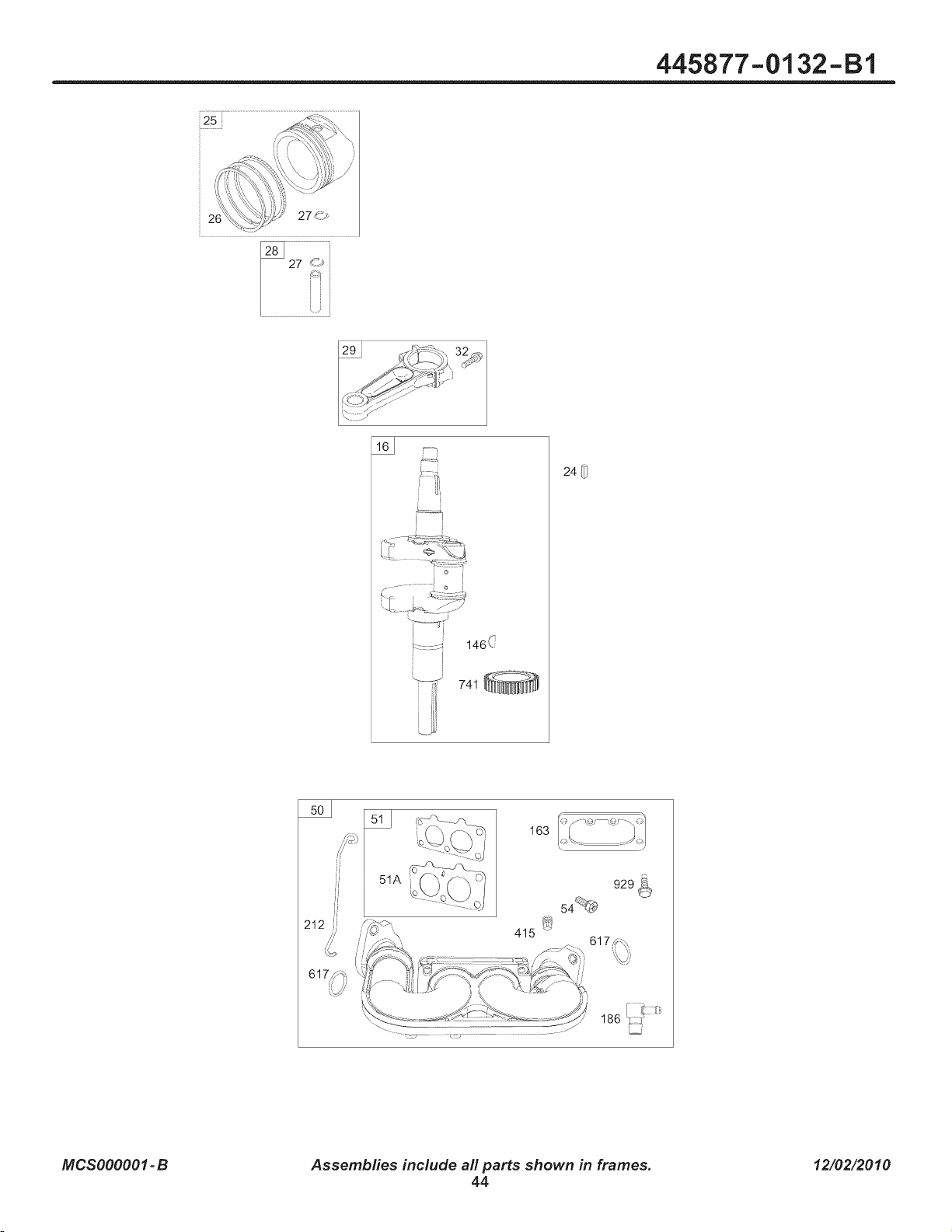
445877-0132-B1
25i
146(:
741 _-_,'_
_NNN
24
163
929 Q1
54_
186 L_g;_
MCSOOOOO1-B
Assemblies include all parts shown in frames.
44
12/02/2010

445877-0132-B1
REF. PART
NO. NO. DESCRIPTION
16 796237 Crankshaft
24 222698s Key-Flywheel
25 793560 Piston Assembly
(Standard)
....... Note .....
793563 Piston
Assembly
(.020" Oversize)
26 793561 Ring Set
(Standard)
....... Note .....
792073 Ring Set
(.020" Oversize)
REF. PART
NO. NO. DESCRIPTION
REF. PART
DESCRIPTIONNO. NO.
212 695238
415 690283
617 697891
27 690975 Lock-Piston Pin
28 696581 Pin-Piston
29 796209 Rod-Connecting
32 690976 Screw
(Connecting Rod)
50 695241 Manifold-intake
51 795123 Gasket-Intake
51A 690950 Gasket-Intake
54 699816 Screw
(Intake Manifold)
146 690979 Key-Timing
163 691001 Gasket-Air Cleaner
186 795985 Connector-Hose
(Intake Manifold)
741 690980
929 695239
Link-Throttle
Plug
(Oil Pressure
Switch Hole)
Seat-O Ring
(Intake Manifold)
(Red)
Gear-Timing
Screw
(Choke
Control Bracket)
MCSOOOOO1-B
Assemblies include all parts shown in frames.
45
12/02/2010
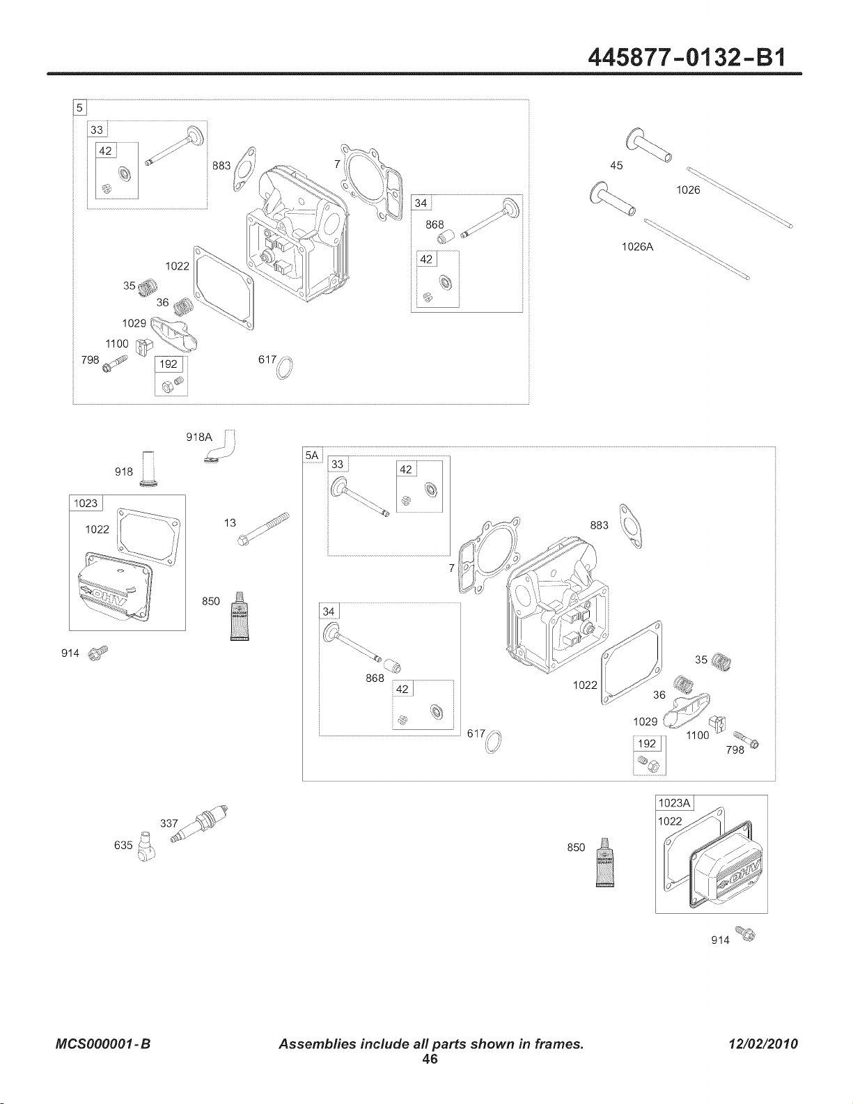
445877-0132-B1
1022
1029
1100 _
79_j _ ....
883
34 /_
868 _/
45
1026 _'_._.._
1026A \'_
918
914 _$_
918A
13
85O
7
883
1022
1029
635
85O
914_
MCSOOOOO1-B
Assemblies include all parts shown in frames.
46
12/02/2010

445877-0132-B1
REF. PART
NO. NO. DESCRIPTION
5 799088 Head-Cylinder
(Cylinder 1)
5A 799089 Head-Cylinder
(Cylinder 2)
693997 Gasket-Cylinder Head
REF. PART
NO. NO. DESCRIPTION
192 690083 Adjuster-Rocker Arm
337 491055s Plug-Spark
617 697891 Seat-O Ring
(Intake Manifold)
(Red)
REF. PART
NO. NO. DESCRIPTION
918
918A
1022
1023
797408 Hose-Vacuum
793147 Hose-Vacuum
690971 Gasket-Rocker Cover
793146 Cover-Rocker
(Cylinder 1)
7
13 793988 Screw
(Cylinder Head)
33 793557 Valve-Exhaust
34 793556 Valve-Intake
35 694865 Spring-Valve
(I ntake)
36 694865 Spring-Valve
(Exhaust)
42 499586 Keeper-Valve
45 690977 Tappet-Valve
635 66538s Boot-Spark Plug
798 697890 Screw
(Rocker Arm)
850 100106 Sealant-Liquid
868 690968 Seal-Valve
883 690970 Gasket-Exhaust
914 691127 Screw
(Rocker Cover)
1023A
1026
1026A
1029
1100
499600 Cover-Rocker
(Cylinder2)
690981 Rod-Push
(Steel)
690982 Rod-Push
(Aluminum)
690972 Arm-Rocker
791959 Pivot-Rocker Arm
MCSOOOOO1-B
Assemblies include all parts shown in frames.
47
12/02/2010
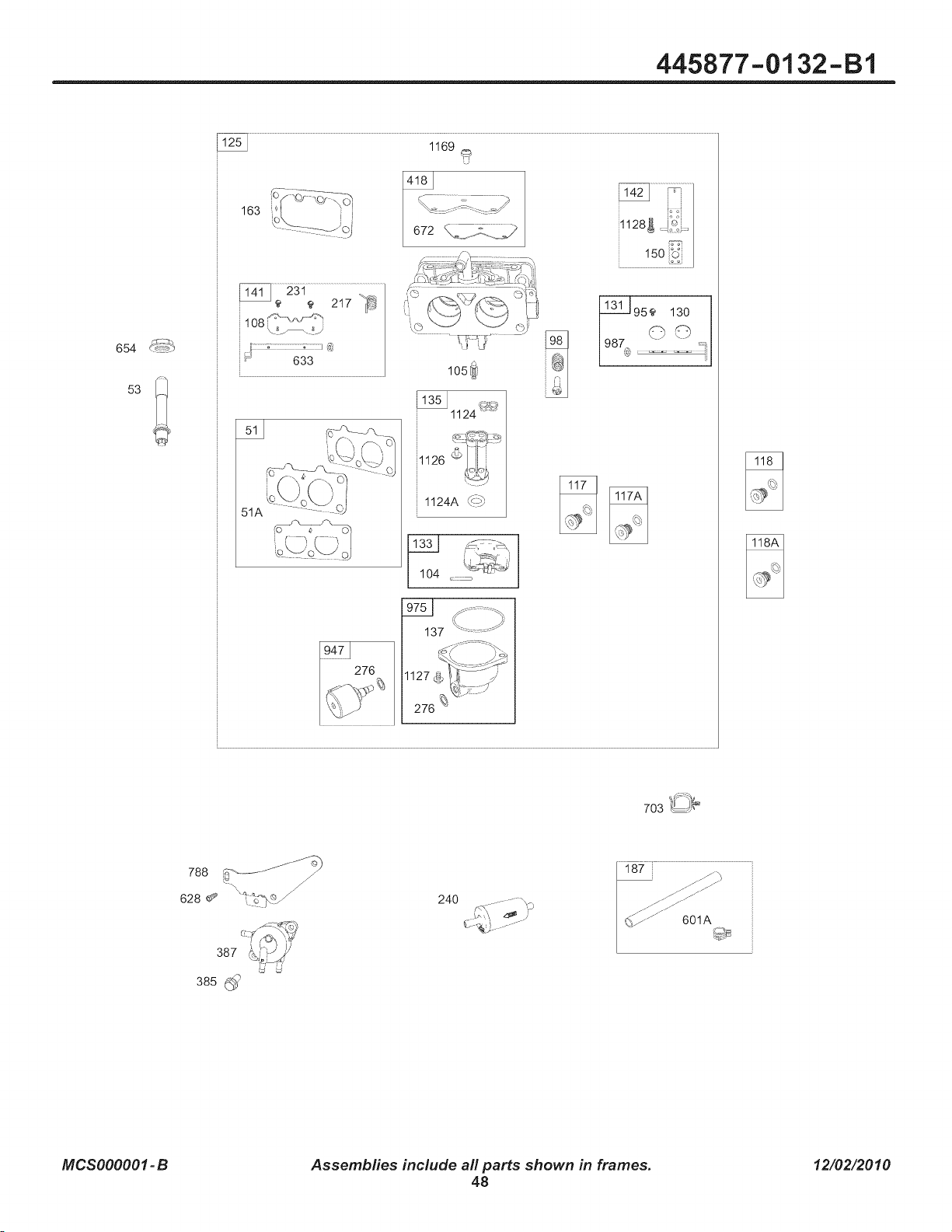
445877-0132-B1
654
53
163
1169
108 _
i_ 633
51A
I05_
1126 !_-
t. _j
1124A (_
l 104 .......
9751 f ........ -__,
137 _ _
131_95e 130
788
628 ®_ ,, o:.,_@_,_j/
387
385
24O
187
MCSOOOOO1-B
Assemblies include all parts shown in frames.
48
12/02/2010

445877-0132-B1
REF. PART
NO. NO. DESCRIPTION
51 795123
51A 690950
53 690951
95 690718
98 699721
104 694918
105 797410
108 699723
117 792296
117A 842627
118 699457
118A 699733
125 796227
130 690993
131 499805
133 699724
135 699729
137 690994
141 796228
Gasket-I ntake
Gasket-I ntake
Stud
(Carburetor)
Screw
(Throttle Valve)
Kit-Idle Speed
Pin-Float Hinge
Valve-Float Needle
REF. PART
NO. NO. DESCRIPTION
REF. PART
DESCRIPTIONNO. NO.
654 690958
672 690234
703 691010
788 793145
Valve-Choke
Jet-Main
(Standard)
(Left Jet)
Jet-Main
(Standard)
(Right Jet)
Jet-Main
(High Altitude)
(Left Jet)
Jet-Main
(High Altitude)
(Right Jet)
Carburetor
Valve-Throttle
Kit-Throttle Shaft
Float-Carburetor
Tube-Fuel Transfer
Gasket-Float Bowl
Kit-Choke Shaft
142 699726 Nozzle-Carburetor
150 690995 Gasket-Nozzle
163 691001 Gasket-Air Cleaner
187 791766 Line-Fuel
(Cut to
Required Length)
217 695409 Spring-Choke Return
231 690718 Screw
(Choke Valve)
240 695666 Filter-Fuel
947 798779
975 798778
276 695410 Washer-Sealing
385 797409 Screw
(Fuel Pump)
(Used After Code Date
09081100).
....... Note .....
697551 Screw
(Fuel Pump)
(Used Before Code
Date 09081200).
387 808656 Pump-Fuel
418 795912 Plate-Carburetor
601A 691038 Clamp-Hose
(Black)
628 691108 Screw
(Fuel Pump Bracket)
(Used Before Code
Date 09081200).
633 699813 Seat-
Choke/Throttle Shaft
(Choke Shaft)
987 691000
1124 690988
1124A 841653
1126 690991
1127 695407
1128 690990
1169 690990
Nut
(Carburetor)
Gasket-
Carburetor Plate
Clip
Bracket-Fuel Pump
(Used Before Code
Date 09081200).
Solenoid-Fuel
Bowl-Float
Seal-Throttle Shaft
SeaI-O Ring
(Fuel Transfer Tube)
SeaI-O Ring
(Fuel Transfer Tube)
Screw
(Fuel Transfer Tube)
Screw
(Float Bowl)
Screw
(Carburetor Nozzle)
Screw
(Carburetor
Cover Plate)
MCSOOOOO1-B
Assemblies include all parts shown in frames.
49
12/02/2010
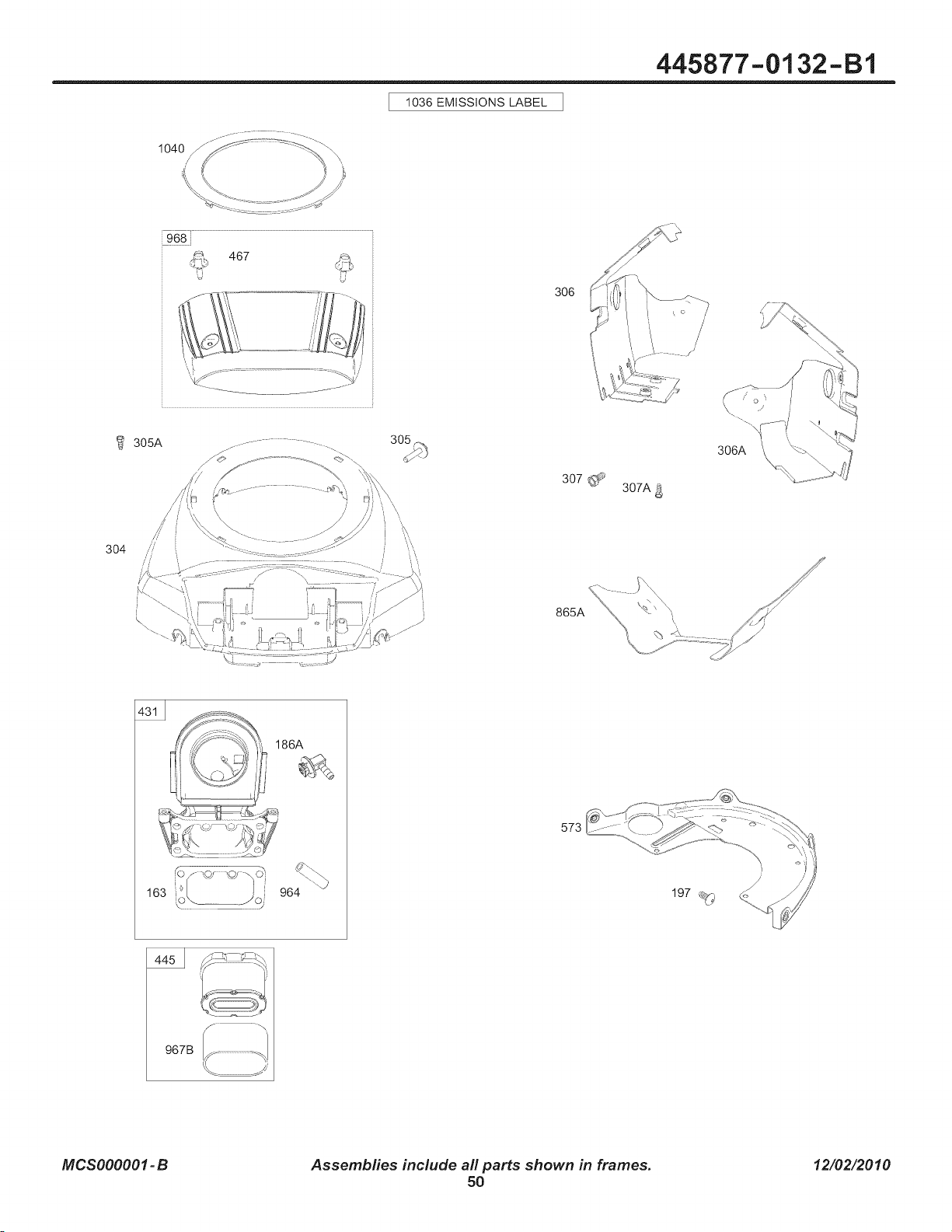
1036 EMISSIONS LABEL
445877-0132-B1
i968 i
467
J
,, _ ],
306
305A
3O4
307
307A
306A
865A
431
163
964
573
967B
MCSOOOOO1-B
Assemblies include all parts shown in frames.
50
12/02/2010

445877-0132-B1
REF. PART
NO. NO. DESCRIPTION
163 691001 Gasket-Air Cleaner
186A 799158 Connector-Hose
(EVAP System)
197 697820 Screw
(Back Plate)
304 797407 Housing-Blower
305 691005 Screw
(Blower Housing)
305A 790690 Screw
(Blower Housing)
(Blower Housing to
Intake Elbow)
REF. PART
NO. NO.
306 798855
306A 796852
307 697551
307A 691003
DESCRIPTION
Shield-Cylinder
(Cylinder 2)
Shield-Cylinder
(Cylinder 1)
Screw
(Cylinder Shield)
(1/4-20x.66)
Screw
(Cylinder Shield)
(10-24x.437)
Elbow-Intake
Filter-
Air Cleaner Cartridge
REF. PART
NO. NO. DESCRIPTION
467 790697 Knob-Air Cleaner
573 790444 Plate-Back
865A 792286 Cover-Air Guide
(Valley)
964 799158 Cap-Connector
967B 792303 Filter-Pre Cleaner
968 795120 Cover-Air Cleaner
1036 Label- Emissions
(Available from a
Briggs & Stratton
Authorized Dealer)
1040 791237 Plate-Trim
431 798860
445 792105
MCSOOOOO1-B
Assemblies include all parts shown in frames.
51
12/02/2010

445877-0132-Ell
747
1005
668 [! 668A
1070
332 _
75 \==-S
23
789
789B
789A
877 ___ _<_
729
1054
334
851 _
1119
1012
18_
209 _\,_
_,X 211
801
310
I1o9ol
i
802 b C<O_ U_
MCSOOOOO1-B
Assemblies include all parts shown in frames.
52
12/02/2010
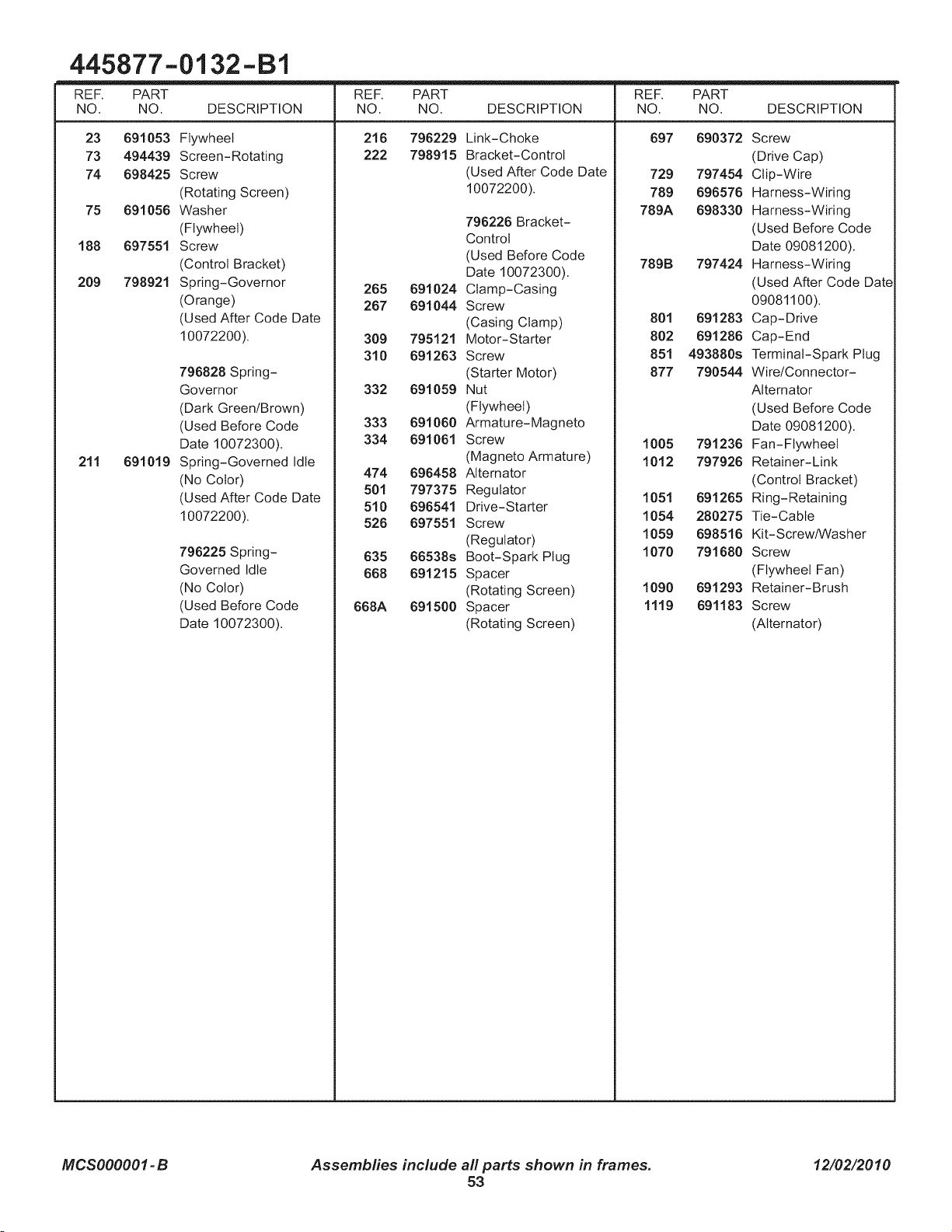
445877-0132-B1
REF. PART
NO. NO. DESCRIPTION
23 691053 Flywheel
73 494439 Screen-Rotating
74 698425 Screw
(Rotating Screen)
75 691056 Washer
(Flywheel)
188 697551 Screw
(Control Bracket)
209 798921 Spring-Governor
(Orange)
(Used After Code Date
10072200).
211 691019
796828 Spring-
Governor
(Dark Green/Brown)
(Used Before Code
Date 10072300).
Spring-Governed Idle
(No Color)
(Used After Code Date
10072200).
796225 Spring-
Governed Idle
(No Color)
(Used Before Code
Date 10072300).
REF. PART
DESCRIPTION
Link-Choke
Bracket-Control
(Used After Code Date
10072200).
NO. NO.
216 796229
222 798915
REF. PART
DESCRIPTIONNO. NO.
697 690372
729 797454
789 696576
789A 698330
789B 797424
801 691283
802 691286
851 493880s
877 790544
1005 791236
1012 797926
1051 691265
1054 280275
1059 698516
1070 791680
796226 Bracket-
Control
(Used Before Code
Date 10072300).
265 691024 Clamp-Casing
267 691044 Screw
(Casing Clamp)
309 795121 Motor-Starter
310 691263 Screw
(Starter Motor)
332 691059 Nut
(Flywheel)
333 691060 Armature-Magneto
334 691061 Screw
(Magneto Armature)
474 696458 Alternator
501 797375 Regulator
510 696541 Drive-Starter
526 697551 Screw
(Regulator)
635 66538s Boot-Spark Plug
668 691215 Spacer
(Rotating Screen)
668A 691500 Spacer
(Rotating Screen)
1090 691293
1119 691183
Screw
(Drive Cap)
Clip-Wire
Harness-Wiring
Harness-Wiring
(Used Before Code
Date 09081200).
Harness-Wiring
(Used After Code Date
09081100).
Cap-Drive
Cap-End
Terminal-Spark Plug
Wire/Connector-
Alternator
(Used Before Code
Date 09081200).
Fan- Flywheel
Retainer-Link
(Control Bracket)
Ring-Retaining
Tie-Cable
Kit-Screw/Washer
Screw
(Flywheel Fan)
Retainer- Brush
Screw
(Alternator)
MCSOOOOO1-B
Assemblies include all parts shown in frames.
53
12/02/2010
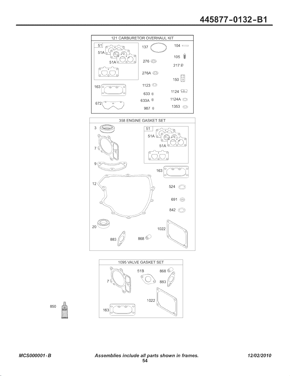
445877-0132-B1
121 CARBURETOR OVERHAUL KIT
137 ,_.. _._
105
276 6_
217_
276A _>)
150
1123 _>P
1124 _J_3,
633 ®
633A _¢ 1124A ¢_
987 @ 1353 <_?p
358 ENGINE GASKET SET
51A
51A _o-_ o _ oJ
12
524 _..#,
691 F_z5
842 xi:%
\\: J
2O
883
1022
868 _-_
85O
1095 VALVE GASKET SET
51B
883
1022
MCSOOOOO1-B
Assemblies include all parts shown in frames.
54
12/02/2010
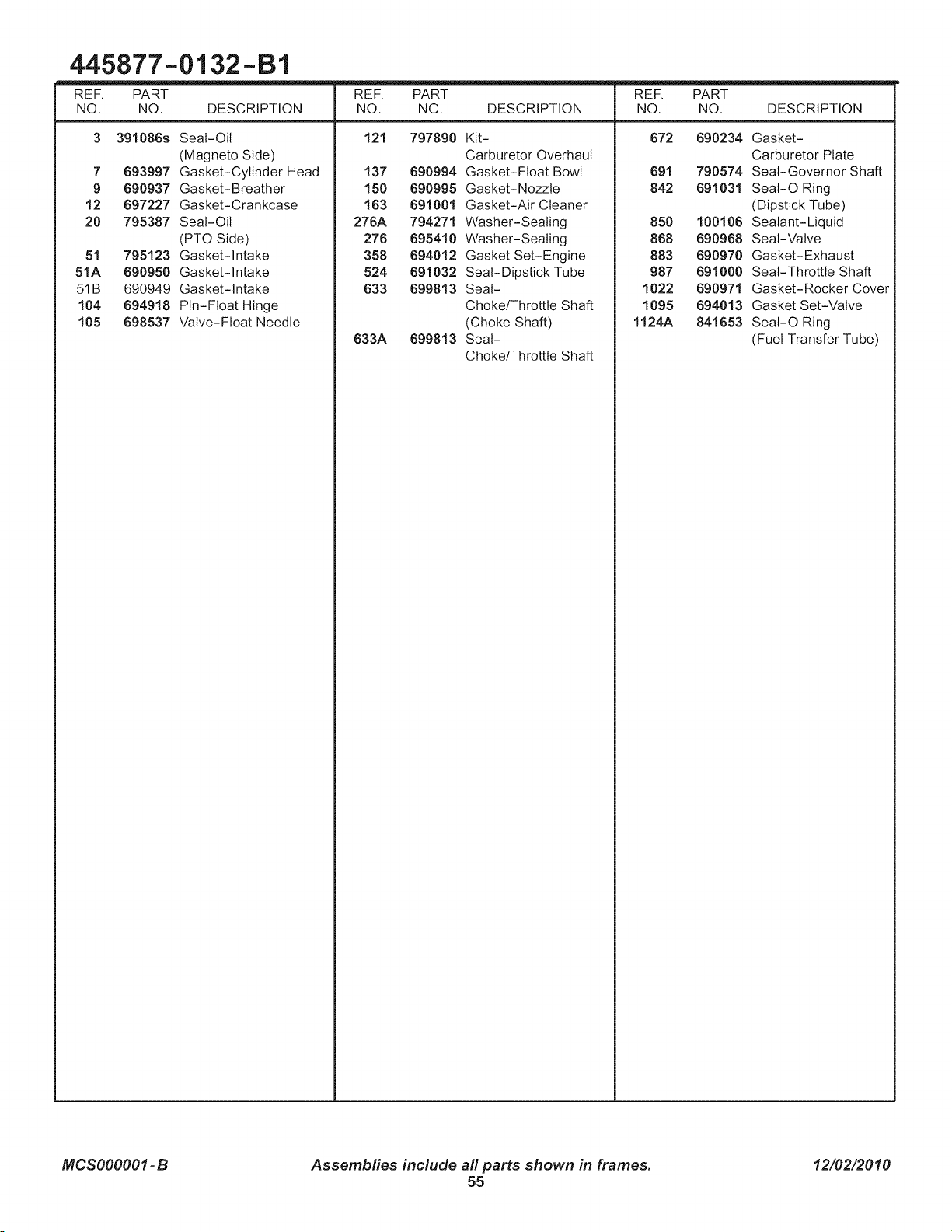
445877-0132-B1
REF. PART
NO. NO. DESCRIPTION
3 391086s Seat-Oil
(Magneto Side)
7 693997 Gasket-Cylinder Head
9 690937 Gasket-Breather
12 697227 Gasket-Crankcase
20 795387 Seal-Oil
(PTO Side)
51 795123 Gasket-Intake
51A 690950 Gasket-Intake
51B 690949 Gasket-Intake
104 694918 Pin-Float Hinge
105 698537 Valve-Float Needle
REF. PART
NO. NO. DESCRIPTION
121 797890 Kit-
Carburetor Overhaul
137 690994 Gasket-Float Bowl
150 690995 Gasket-Nozzle
163 691001 Gasket-Air Cleaner
276A 794271 Washer-Seating
276 695410 Washer-Seating
358 694012 Gasket Set-Engine
524 691032 Seal-Dipstick Tube
633 699813 Seal-
Choke/Throttle Shaft
(Choke Shaft)
633A 699813 Seat-
Choke/Throttle Shaft
REF. PART
DESCRIPTIONNO. NO.
672 690234
691 790574
842 691031
850 100106
868 690968
883 690970
987 691000
1022 690971
1095 694013
1124A 841653
Gasket-
Carburetor Plate
Seat-Governor Shaft
SeaI-O Ring
(Dipstick Tube)
Sealant-Liquid
Seal-Valve
Gasket-Exhaust
Seat-Throttle Shaft
Gasket-Rocker Cover
Gasket Set-Valve
SeaI-O Ring
(Fuel Transfer Tube)
MCSOOOOO1-B
Assemblies include all parts shown in frames.
55
12/02/2010

Hardwareidentification& TorqueSpecifications
Torque Specification Chart
FORSTANDARDMETRICMACHINEHARDWARE(Tolerance± 20%)
Preper_
Class
SizeOf
Hardware
5.88
13.44
26.4
44,64
5.2
7.7
15
26
42
64
89
126
169
217
326
435
590
759
988
M3
M4
M5
M6
M7
M8
MIO
M12
M14
M16
M18
M20
M22
M24
M27
M30
M33
M36
M39
in/Ibs
ft/Ibs Nm.
.56
1.28
2.5O
4.3
7.1
10.5
21
36
58
88
121
171
230
295
435
59O
8OO
1030
1340
@
Class8.8
in/Ibs
&ribs Nm.
13.44 1.28
30.72 2.90
6O.96 5.75
7.3 9.9
12.1 !6.5
17.7 24
35 48
81 83
101 132
147 200
292 275
298 390
399 530
497 375
733 995
995 1350
1349 1830
1740 2360
2249 3050
in/Ibs
flj]bs Nm.
!9.2 1.80
43.44 4.!0
5.97 8.10
16.3 14
18.9 23
25 34
50 67
88.2 117
136 185
21O 285
287 390
495 550
559 745
798 960
1932 1400
1461 1900
1902 2580
2441 33!0
3183 4290
in/Ibs
fl/Ibs
22.92
52.56
7.15
12.1
19.9
29
59
183
182
250
348
488
856
848
1239
1881
2278
2835
3798
The guides and ruler furnished below are designed to
help you select the appropriate hardware.
Nm.
2.15
4.95
9.7
16.5
27
4O
81
140
220
340
470
66O
89O
1!40
1680
2280
3090
3980
5150
jillIIIIjllllIIIIIIII
0 10 20 30
©
Nu_8
Thread
Diameter(ram)
Inside Threads
Diameter(in) per inch
Nut, 1/2-16
o I
,I,J,I, ,I,J,I,
I I I I I I
40 50 60 70 80 90 loo
_r_LD_iameter
Body Length_
Screw, iris= 1.25 x 25
Thread Distancebetween Body
Diameter(mm) threads(mm) Length(ram)
Body Threads Body
Diameter per rich Length(in)
Screw, 1/2= 16 x 2
3 4
Standard Hardware Sizing
When a washer or nut is identified as1/2" (M8), this is
the Nominal siz& meaning the inside diameteris 1/2 inch
(8ram metric thread diameter); if a second number is present
it represents the threads per inch (distance between threads).
When bolt or capscrew is identified as1/2 = 16 x 2" (M8 - 1.25 x 50 ),
this means the Nominal size, or body diameter is 1/2 inch (8mm
metric thread diameter), the second number,16, represents the
threads per inch, (1.25 thread diameter).The final number is the
body length of the bolt or screw, 2 inches (50ram).
Torque Specification Chart
FORSTANDARDMACHINEHARDWARE(Tolerance+20%)
=:°'°@ 0 ©
SAEGrads2 8AEGrads5 8AEGrads8
Size Of in/Ibs in/Ibs in/Ibs
Hardware fl/ibs Nm. fl/ibs Nm. fifths Nm.
8-32
8-36
10-24
10-32
1/4-20
1/4-28
5/16-18
5/16-24
3/8-16
3/8-24
7/16-14
7/16-20
1/2-13
1/2-20
9/16-12
9/16-18
5/8-11
5/8-18
3/4-10
3/4-16
7/8-9
7/8-14
1-8
1-12
19 2.1
20 2.3
27 3.1
3! 3.5
66 7.6
76 8.6
11 15.0
12 183
28 27.2
23 31.3
38 40.8
35 47.6
58 68.0
55 74.8
65 88.4
75 102.0
98 122.4
188 136
188 217.6
188 244.8
148 190.4
155 210.8
220 299.2
248 326.4
1. These torque
30 3.4
31 3.5
43 4.9
49 5.5
8 10,9
18 13.6
17 23.1
19 25.8
38 40.8
35 47.6
50 68.0
55 74.8
75 102.0
98 122.4
118 149.6
128 163.2
158 204.0
188 244.8
268 353.6
388 408.0
488 544.0
448 598.4
588 788.8
840 870.4
41 4.6
43 4.9
60 6.8
68 7.7
12 16.3
14 19.0
25 34.0
29 34.0
45 61.2
58 68.0
78 95.2
88 108.8
118 149.6
128 163.2
158 204.0
178 231.2
228 299.2
248 326.4
388 525.0
420 571.2
688 816.0
688 897.6
988 1,244.0
1,888 1,360.0
NOTES
values are to be used for all hardware
excluding: Iocknuts, self-tapping screws, thread forming
screws, sheet metal screws and socket head setscrews.
2. Recommended seating torque values for Iocknuts:
a. for prevailing torque Iocknuts - use 65% of grade5
torques.
b. for flange whizmock nuts and screws - use t 35% of
grade 5 torques.
3. Unless otherwise noted on assembly drawings, all torque
values must meet this specification.
Common Hardware Types
HexHeadCapscrew
CarriageBolt
Washer
Lockwasher
HexNut
Wrench & Fastener Size Guide
o o © ©
1/4" Bolt Oh"Nut _16" SO_ Or Nut 3./8" SOft Or Nut 7116" 80it Or Nut
Wrench--7!16" Wrench--I/2" Wrench_/15" Wrench (8off)--5/8"
Wrench (Nut)--11/16 _
M6 BOll ot Nut M8 BO_ Or Net MlO Bolt Ot N_ M12 Bolt Or Nut
Wrench--lOrnm Wrench--13ram Wrench--17ram Wrench--19mlm
1/2" BO_ Or Nut
Wrench--3/4"
M14 Bo[t or Nut
Wrench--22 mrn
PTS - 56

Your Home
For troubleshooting, product manuals and expert advice:
managemylife
www.managemylife.com
For repair - in your home - of all major brand appliances,
lawn and garden equipment, or heating and cooling systems,
no matter who made it, no matter who sold it!
For the replacement parts, accessories and
owner's manuals that you need to do-it-yourself.
For Sears professional installation of home appliances
and items like garage door openers and water heaters.
1-800-4-MY-HOME ® (1-800-469-4663)
Call anytime, day or night (U.S.A. and Canada)
www.sears.com www.sears.ca
Our Home
For repair of carry-in items like vacuums, lawn equipment,
and electronics, call anytime for the location of your nearest
Sears Parts & Repair Service Center
1-800-488-1222 (U.S.A.) 1-800-469-4663 (Canada)
www.sears.com www.sears.ca
To purchase a protection agreement on a product serviced by Sears:
1-800-827-6655 (U.S.A.) 1-800-361-6665 (Canada)
Para pedir servicio de reparaci6n
a domicilio, y para ordenar piezas:
1-888-SU-HOGAR ®
(1-888-784-6427)
Au Canada pour service en fran¢;ais:
1-800-LE-FOYER Mc
(1-800-533-6937)
www.sears.ca
www.sears.com
® Registered Trademark / TMTrademark of KCD IP, LLC in the United States, or Sears Brands, LLC in other countries
@ Marca Registrada / TMMarca de Fabrica de KCD IP, LLC en Estados Unidos, o Sears Brands, LLC in otros paises
MCMarque de commerce / MDMarque d6pos6e de Sears Brands, LLC
