Operator's Manual
I
!!!!!!!_
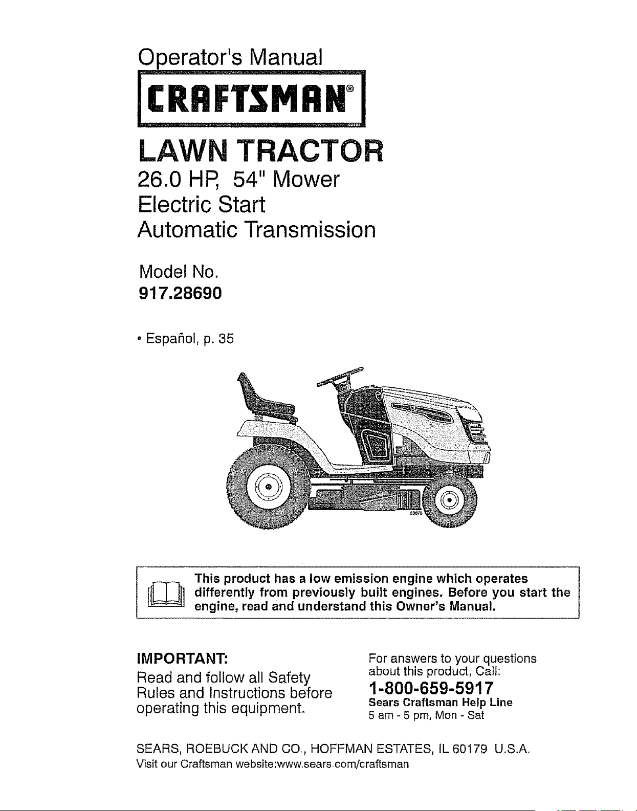
LAWN TRACTOR
26.0 HP, 54" Mower
Electric Start
Automatic Transmission
Model No.
917.28690
• EspaSol, p. 35
This product has a low emission engine which operates
differently from previously built engines. Before start the
you
engine, read and understand this Owner's Manual.
IMPORTANT:
Read and follow all Safety
Rules and Instructions before
operating this equipment°
For answers to your questions
about this product, Call:
1-800-659-5917
Sears Craftsman Help Line
5 am - 5 pm, Mon- Sat
SEARS, ROEBUCK AND CO., HOFFMAN ESTATES, IL 60179 U.S.A.
Visit our Craftsman website:www, searscom/craftsman
Warranty ................................................ 2
Safety Rules .......................................... 3
Product Specifications ........................... 6
Assembly/Pre-Operation ....................... 8
Operation ............................................. 12
Maintenance Schedule ......................... 20
Maintenance ..................................... 20
Service and Adjustments ..................... 24
Storage ................................................ 30
Troubleshooting ................................... 31
Sears Service ........................ Back Cover
LIMITED WARRANTY ON CRAFTSMAN RIDING EQUIPMENT
For two (2) years from the date of purchase, if this Craftsman Riding Equipment is
maintained, lubricated and tuned up according to the instructions in the owner's manual,
Sears wilt repair or replace free of charge any parts that are found to be defective in
material or workmanship according to the guidelines of coverage listed below. Sears will
also provide free labor for these applicable warranted parts for 2 full years. During the
first 30 days of purchase, there will be no charges to service the product at your home
for issues covered by this warranty. (See exclusions below). For your convenience, IN
HOME warranty service will still be available after the first 30 days of purchase, but a trip
charge will apply, This charge will be waived if the Craftsman product is dropped off at an
authorized Sears location, For the nearest authorized Sears location, please call 1-800-4-
MY-HOME®. This warranty applies only while this product is within the United States.
THIS WARRANTY DOES NOT COVER:
• Expendable items which become worn during normal use, including but not limited to
blades, spark plugs, air cleaners, belts, and oil filters.
• Standard Maintenance Servicing, oil changes, or tune-ups
• Tire replacement or repair caused by punctures from outside objects, such as nails,
thorns, stumps, or glass_
, Repairs necessary because of operator abuse, including but not limited to, damage
caused by towing objects beyond the capability of the riding equipment, impacting
objects that bend the frame or crankshaft, or over-speeding the engine.
• Repairs necessary because of operator negligence, including but not limited to, electrical
and mechanical damage caused by improper storage, failure to use the proper grade
and amount of engine oil, failure to keep the deck clear of flammable debris, or failure to
maintain the equipment according to the instructions contained in the owner's manual.
• Engine (fuel system) cleaning or repairs caused by fuel determined to be contaminated or
oxidized (stale). in general, fuel should be used within 30 days of its purchase date,
• Normal deterioration and wear of the exterior finishes, or product iabel replacement.
• Riding equipment used for commercial or rental purposes.
LIMITED WARRANTY ON BATTERY
For ninety (90) days from date of purchase, if any battery included with this riding equipment
proves defective in material or workmanship and our testing determines the battery will
not hold a charge, Sears will replace the battery at no charge. During the first 30 days of
purchase, there will be no charges to replace the battery at your HOME. After the first 30
days, for your convenience, IN-HOME warranty service will still be available but atrip charge
will apply_ This charge will be waived if the Craftsman product is dropped off at an authorized
Sears location. For the nearest authorized Sears location, please call 1-800_4-MY-HOME®.
This battery warranty applies only while this product is within the United States.
This warranty gives you specific legal rights, and you may also have other rights, which
vary, from state to state.
Sears, Roebuck and Co., Hoffman Estates, IL 60179
_DANGER: This cutting machine is capable of amputating hands and feet and
throwing objects. Failure to observe the following safety instructions could result
in serious injury or death.
_kWARNING: In order to prevent ac-
cidental starting when setting up, trans-
porting, adjusting or making repairs,
always disconnect spark plug wire and
place wire where it cannot contact spark
plug.
_,WARNING: Do not coast down a hill in
neutral, you may lose control of the tractor.
_kWARNING: Tow only the attachments
that are recommended by and comply with
specifications of the manufacturer of your
tractor, Use common sense when towing°
Operate only at the lowest possible speed
when on a slope. Too heavy of a load,
while on a slope, is dangerous. Tires can
lose traction with the ground and cause
you to lose control of your tractor°
_WARNING: Engine exhaust, some of
its constituents, and certain vehicle com-
ponents contain or emit chemicals known
to the State of California to cause cancer
and birth defects or ether reproductive
harm.
_WARN1NG: Battery posts, terminals
and related accessories contain lead and
lead compounds, chemicals known to the
State of California to cause cancer and
birth defects or other reproductive harm.
Wash hands after handling.
!. GENERAL OPERATION
• Read, understand, and follow all instruc-
tions on the machine and in the manual
before starting.
. Do not put hands or feet near rotating
parts or under the machine, Keep clear
of the discharge opening at all times,
• Only allow responsible adults, who are
familiar with the instructions, to operate
the machine.
• Clear the area of objects such as rocks,
toys, wire, etc,, which could be picked
up and thrown by the blades°
• Be sure the area is clear of bystand-
ers before operating, Stop machine if
anyone enters the area,
• Never carry passengers.
• Do not mow in reverse unless abso-
lutely necessary. Always look down and
behind before and while backing
• Never direct discharged material toward
anyone. Avoid discharging material
against a wall or obstruction. Material
may ricochet back toward the operator,
Stop the blades when crossing gravel
surfaces°
, Do not operate machine without the
entire grass catcher, discharge guard, or
other safety devices in place and work-
ing,
• Slow down before turning.
• Never leave a running machine unat-
tended, Always turn off blades, set
parking brake, stop engine, and remove
keys before dismounting.
• Disengage blades when not mowing
Shut off engine and wait for all parts to
come to a complete stop before clean-
ing the machine, removing the grass
catcher, or unclogging the discharge
guard°
• Operate machine only in daylight or
good artificial light.
• Do not operate the machine while under
the influence of alcohol or drugs,
• Watch for traffic when operating near or
crossing roadways.
• Use extra care when loading or unload-
ing the machine into a trailer or truck.
• Always wear eye protection when oper-
ating machine,
• Data indicates that operators, age 60
years and above, are involved in a large
percentage of riding mower-related in-
juries. These operators should evaluate
their ability to operate the riding mower
safely enough to protect themselves and
others from serious injury.
• Follow the manufacturer's recommen-
dation for wheel weights or counter-
weights.
• Keep machine free of grass, leaves or
other debris build-up which can touch
hot exhaust / engine parts and burn, Do
not allow the mower to plow leaves or
other debris which can cause build-up
to occur, Clean any oil or fuel spillage
before operating or storing the machine
Allow machine to cool before
storage.
!1.SLOPE OPERATION
Slopesare a majorfactor relatedto loss of
controlandtip-overaccidents,whichcan
resultin severeinjuryordeath. Opera-
tion onall slopesrequiresextracaution. If
you cannotback up theslopeor if you feel
uneasyon it, donot mowit_
. Mowup anddownslopes,notacross.
• Watchfor holes,ruts,bumps,rocks,or
otherhiddenobjects. Uneventerrain
couldoverturnthe machine°Tallgrass
can hideobstacles°
• Choosea lowgroundspeedsothat you
will nothaveto stopor shiftwhile on the
slope.
• Do not mowon wet grass.Tiresmay
losetraction_
Alwayskeepthe machinein gearwhen
goingdownslopes,Do notshift to neu-
tral and coastdownhill.
• Avoidstarting,stopping,or turning on a
slope, tf the tires losetraction, disen-
gagethe bladesand proceedslowly
straightdownthe slope°
• Keepall movementon the slopes slow
andgradual. Do not makesudden
changesin speedor direction,which
couldcausethe machineto roll over.
• Useextra carewhileoperatingmachine
with grasscatchersor otherattach-
ments;theycan affectthe stabilityof the
machine.Do no use on steepslopes.
• Do not try to stabilizethe machineby
puttingyour foot on the ground,
• Do not mowneardrop-offs,ditches,
or embankments,The machinecould
suddenlyrollover if a wheel is overthe
edgeor if the edge cavesin
II!. CHILDREN
Tragicaccidentscan occur if the operator
is not alert to the presence of children,
Childrenare oftenattractedto the machine
and the mowing activity. Never assume
that children wit! remain where you last
sawthem,
• Keepchildrenoutof the mowingarea
and in the watchfulcareof a responsible
adultotherthan the operator.
• Be alert andturn machineoff if a child
entersthe area.
• Beforeandwhile backing,look behind
and downfor small children.
• Nevercarrychildren,evenwith the
bladesshutoff, They mayfall off and
be seriouslyinjuredor interferewith
safemachineoperation.Childrenwho
havebeengivenridesin the pastmay
suddenlyappearin the mowingareafor
anotherrideand be run over or backed
over bythe machine,
• Neverallowchildrento operatethe
machine.
• Useextracare whenapproachingblind
corners,shrubs,trees,or otherobjects
that mayblockyour viewof a child.
IV.TOWING
• Towonlywith a machinethat has a
hitchdesignedfor towing,Do not attach
towedequipmentexceptat the hitch
point.
• Followthemanufacturer'srecommenda-
tion for weightlimitsfor towedequip-
mentandtowingon slopes.
, Neverallowchildrenor othersin oron
towedequipment.
• On slopes,theweight ofthe towed
equipmentmaycauselossof traction
and lossof control.
• Travelslowlyand allowextradistanceto
stop°
V. SERVICE
SAFE HANDLINGOF GASOLINE
Toavoidpersonalinjuryor property
damage,use extremecare in handling
gasoline.Gasolineis extremelyflammable
andthevapors are explosive.
• Extinguishall cigarettes,cigars,pipes,
and othersourcesof ignition.
• Useonlyapprovedgasolinecontainer.
• Neverremovegas cap or addfuel with
the enginerunning_Allowengineto cool
beforerefueling.
• Neverfuelthe machineindoors.
• Neverstorethe machineorfuel con-
tainerwherethereis an openflame,
spark,or pilot lightsuchas on a water
heaterorother appliances.
• Neverfill containersinsidea vehicleor
on a truck ortrailer bedwith plasticliner.
Alwaysplacecontainerson the ground
awayfrom your vehiclewhenfilling.
• Removegas-poweredequipmentfrom
thetruckor trailerand refuelit onthe
ground.Ifthis is not possible,then
refuelsuch equipmentwith a portable
container,ratherthanfrom a gasoline
dispensernozzle.
• Keepthe nozzlein contactwith the rim
ofthe fuel tank or containeropeningat
alltimesuntilfuelingis complete,Do not
usea nozzlelock-opendevice.
, Iffuel is spilledon clothing,change
clothingimmediately,
• Neveroverfillfue! tank.Replacegascap
andtightensecurely.
GENERALSERVICE
• Neveroperatemachinein a closed area.
• Keep all nuts and bolts tight to be sure
the equipment is in safe working condi-
tion.
• Never tamper with safety devices.
Check their proper operation regularly,
• Keep machine free of grass, leaves, or
other debris build-up. Clean oil or fuel
spillage and remove any fuel-soaked
debris, Allow machine to cool before
storing,
• If you strike a foreign object, stop and
inspect the machine. Repair, if neces-
sary, before restarting.
• Never make any adjustments or repairs
with the engine running.
• Check grass catcher components and
the discharge guard frequently and re-
place with manufacturer's recommended
parts, when necessary.
• Mower blades are sharp. Wrap the
blade or wear gloves, and use extra cau-
tion when servicing them.
• Check brake operation frequentIy. Adjust
and service as required,
• Maintain or replace safety and instruc-
tion labels, as necessary.
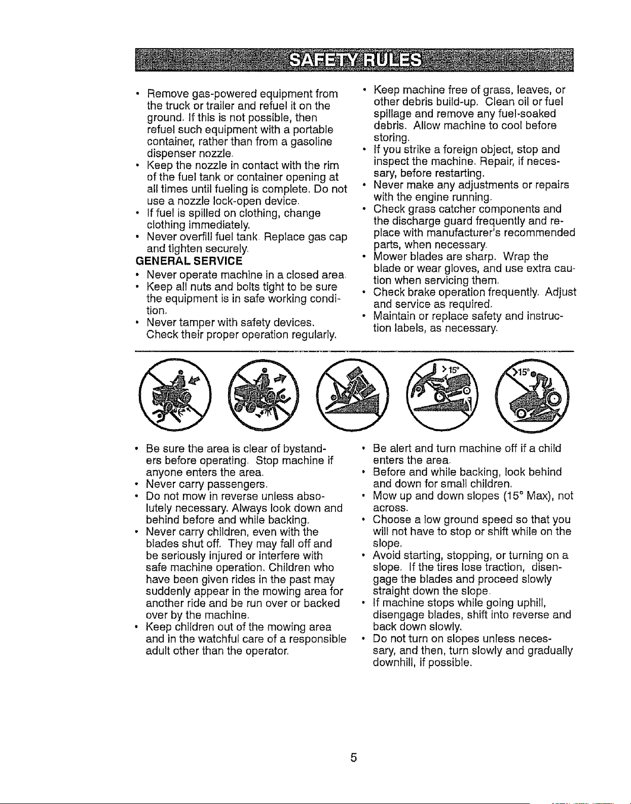
• Be sure the area is ctear of bystand-
ers before operating. Stop machine if
anyone enters the area.
• Never carry passengers.
• Do not mow in reverse unless abso-
lutely necessary. Always look down and
behind before and while backing.
• Never carry children, even with the
blades shut off. They may fall off and
be seriously injured or interfere with
safe machine operation° Children who
have been given rides in the past may
suddenly appear in the mowing area for
another ride and be run over or backed
over by the machine.
• Keep children out of the mowing area
and in the watchful care of a responsible
adult other than the operator.
• Be alert and turn machine off if a child
enters the area.
• Before and while backing, look behind
and down for smal] children,
• Mow up and down slopes (15 ° Max), not
across,
° Choose a tow ground speed so that you
will not have to stop or shift while on the
slope°
• Avoid starting, stopping, or turning on a
slope_ If the tires lose traction, disen-
gage the blades and proceed slowty
straight down the slope
• If machine stops while going uphill,
disengage blades, shift into reverse and
back down slowly,
• Do not turn on slopes unless neces-
sary, and then, turn slowly and gradually
downhill, if possible,
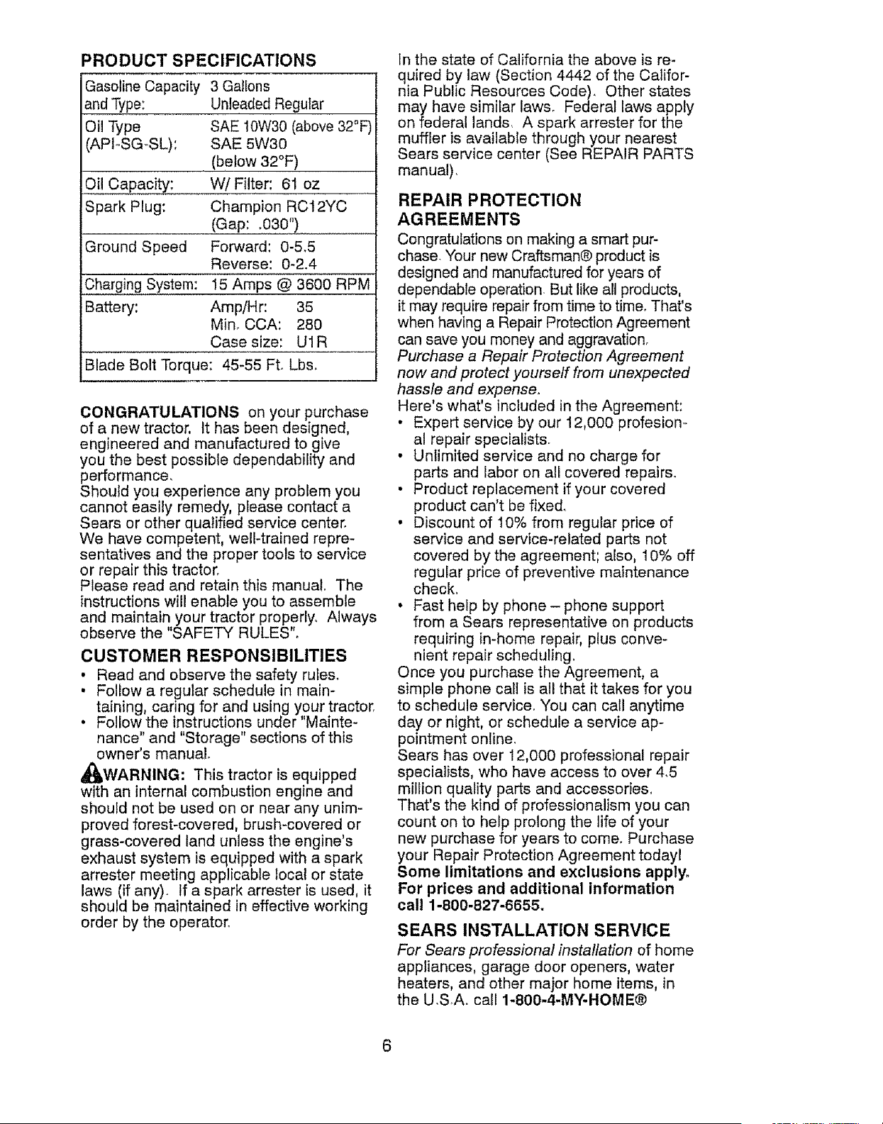
PRODUCT SPECIFICATIONS
Gasoline Capacity
and Type:
Oil Type
(APIoSG-SL):
Oil Capacity:
Spark Plug:
Ground Speed
Charging System:
Battery:
3 Gallons
Unleaded Regular
SAE 10W30 (above 32°F
SAE 5W30
(below 32°F)
W/Filter: 61 oz
Champion RCI 2YC
(Gap: .030")
Forward: 0-5,5
Reverse: 0-2.4
I5 Amps @ 3600 RPM
Amp!Hr: 35
Min, CCA: 280
Case size: U1R
Blade Bolt Torque: 45-55 Ft. Lbs.
CONGRATULATIONS on your purchase
of a new tractor, It has been designed,
engineered and manufactured to give
you the best possible dependability and
performance,
Should you experience any problem you
cannot easily remedy, please contact a
Sears or other qualified service center.
We have competent, well-trained repre-
sentatives and the proper tools to service
or repair this tractor.
Please read and retain this manual The
instructions will enable you to assemble
and maintain your tractor properly, Always
observe the "SAFETY RULES"_
CUSTOMER RESPONSIBILITIES
. Read and observe the safety rules.
• Follow a regular schedule in main-
taining, caring for and using your tractor,
• Follow the instructions under"Mainte-
nance" and "Storage" sections of this
owner's manual.
,_WARNING: This tractor is equipped
with an internal combustion engine and
should not be used on or near any unim-
proved forest-covered, brush-covered or
grass-covered land unless the engine's
exhaust system is equipped with a spark
arrester meeting applicable local or state
laws (if any). If a spark arrester is used, it
should be maintained in effective working
order by the operator.
In the state of California the above is re-
quired by law (Section 4442 of the Califor-
nia Public Resources Code), Other states
may have similar laws, Federal laws apply
on federal lands, A spark arrester for the
muffler is available through your nearest
Sears service center (See REPAIR PARTS
manual),
REPAIR PROTECTION
AGREEMENTS
Congratulations on making a smart pur-
chase Your new Craftsman® product is
designed and manufactured for years of
dependable operation But like all products,
it may require repair from time to time. That's
when having a Repair Protection Agreement
can save you money and aggravation.
Purchase a Repair Protection Agreement
now and protect yourself from unexpected
hassle and expense.
Here's what's included in the Agreement:
• Expert service by our 12,000 profesion-
al repair specialists.
• Unlimited service and no charge for
parts and labor on all covered repairs.
• Product replacement if your covered
product can't be fixed,
• Discount of 10% from regular price of
service and service-related parts not
covered by the agreement; also, 10% off
regular price of preventive maintenance
check,
, Fast help by phone - phone support
from a Sears representative on products
requiring in-home repair, plus conve-
nient repair scheduling,
Once you purchase the Agreement, a
simple phone call is all that it takes for you
to schedule service. You can call anytime
day or night, or schedule a service ap-
pointment online,
Sears has over 12,000 professional repair
specialists, who have access to over 4,5
million quality parts and accessories,
That's the kind of professionalism you can
count on to help prolong the life of your
new purchase for years to come. Purchase
your Repair Protection Agreement todayl
Some limitations and exclusions apply.
For prices and additional information
call 1-800-827-6655,
SEARS INSTALLATION SERVICE
For Sears professional installation of home
appliances, garage door openers, water
heaters, and other major home items, in
the U.SA. call 1-800-4-MY-HOME®
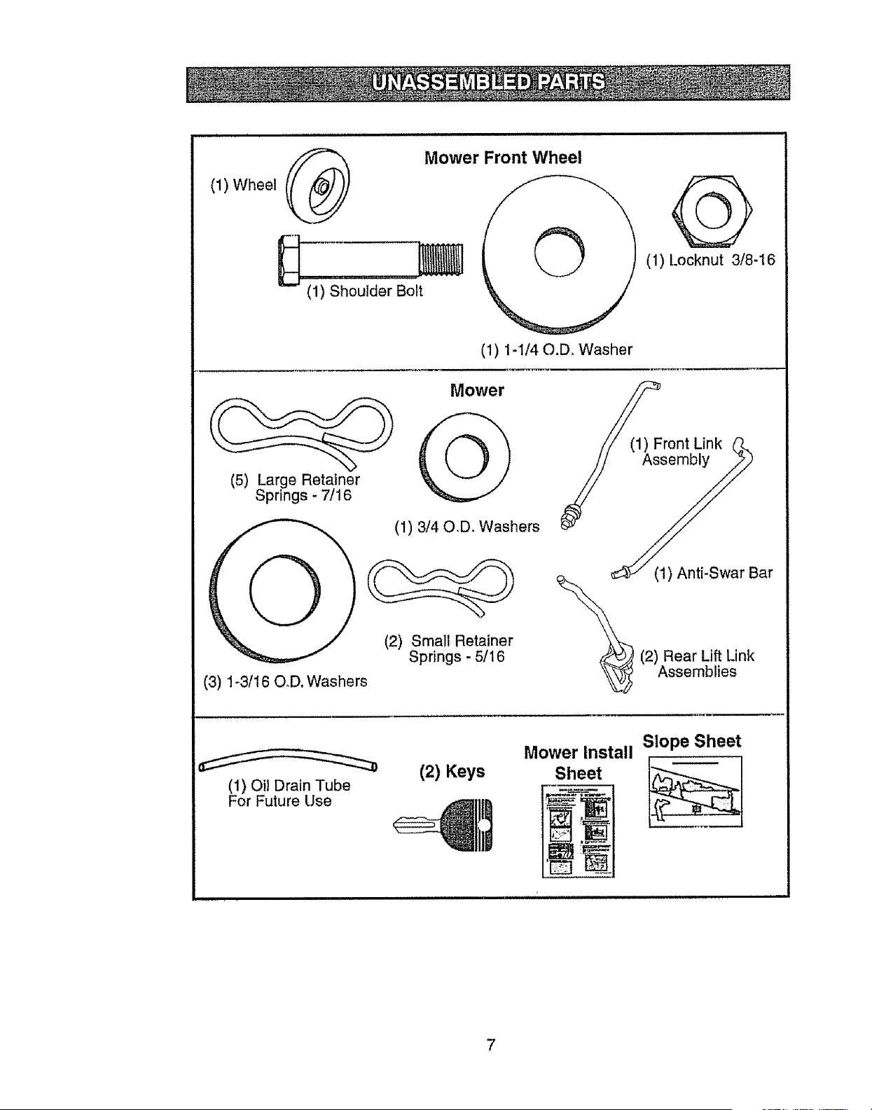
(1)Wheel
Mower Front Wheel
(1) Shoulder Bolt
(1) 1-1/40.D, Washer
(1) Locknut 3/8-16
(5) Large Retainer
Springs - 7/16
(3) 1-3/16 O_D. Washers
Mower
(1) 3/40,D_ Washers
(2) Small Retainer
Springs - 5/16
(1) Front Link (_
_y
(1) Anti-Swar Bar
2) Rear Lift Link
Assemblies
(1) OiJDrain Tube
For Future Use
(2) Keys
Mower Install Slope Sheet
Sheet
7
Your new tractor has been assembled at the factory with the exception of those parts left
unassembled for shipping purposes,
TOOLS REQUIRED FOR ASSEMBLY
A socket wrench set will make assembly
easier, Standard wrench sizes you need
are listed below.
(1) 3/4" wrench (1) Pliers
(1) 9/16" wrench (1) Utility knife
(1) Tire pressure gauge
When right or left hand is mentioned in
this manual, it means, from your point of
view, when you are in the operating posi-
tion (seated behind the steering wheel),
TO REMOVE TRACTOR FROM
CARTON
UNPACK CARTON
1, Remove all accessible loose parts and
parts cartons from carton,
2o Cut along dashed lines on al! four pan-
els of carton. Remove end panels and
lay side panels flat,
3, Remove mower and packing materials,
4. Check for any additional loose aprts or
cartons and remove.
CHECK BATTERY
1, Lift hood to raised position,
NOTE: If this battery is put into service
after month and year indicated on label
(L) (label is located between terminals)
charge battery for minimum of one hour at
6-10 amps, (See "BATTERY" in Mainte-
nance section of this manual for charging
instructions),
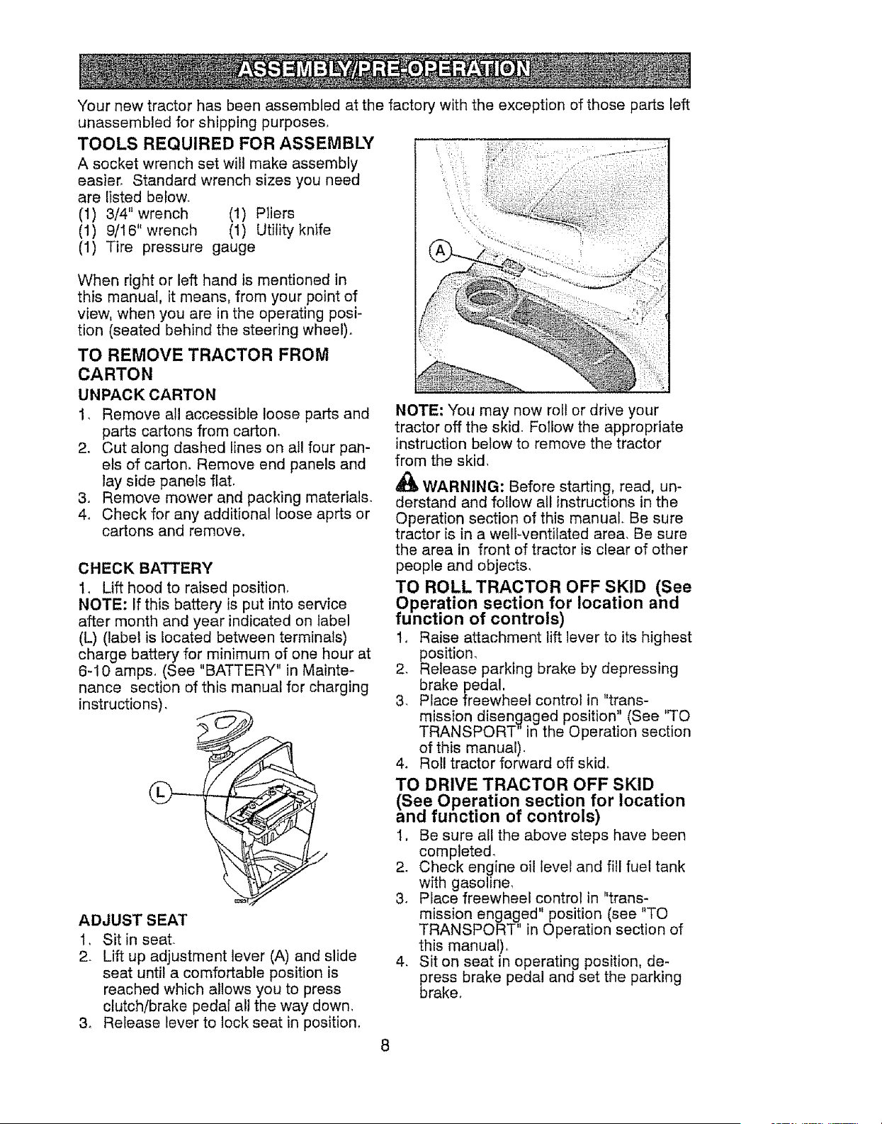
ADJUST SEAT
1, Sit in seat.
2. Lift up adjustment lever (A) and slide
seat until a comfortable position is
reached which allows you to press
clutch/brake pedal all the way down,
3, Retease lever to lock seat in position.
NOTE: You may now roll or drive your
tractor off the skid. Follow the appropriate
instruction below to remove the tractor
from the skid,
WARNING: Before starting, read, un-
derstand and follow all instructions in the
Operation section of this manual. Be sure
tractor is in a well-ventilated area, Be sure
the area in front of tractor is clear of other
people and objects,
TO ROLL TRACTOR OFF SKID (See
Operation section for location and
function of controls)
1, Raise attachment lift lever to its highest
position_
2, Release parking brake by depressing
brake pedal.
3, Place freewheel control in "trans-
mission disengaged position" (See %0
TRANSPORT in the Operation section
of this manual).
4. Roll tractor forward off skid.
TO DRIVE TRACTOR OFF SKID
(See Operation section for location
and function of controls)
1, Be sure all the above steps have been
completed,
2. Check engine oil level and fill fuel tank
with gasoline_
3, Place freewheel control in "trans-
mission engaged" position (see "TO
TRANSPORT" in Operation section of
this manual)+
4, Sit on seat in operating position, de-
press brake pedal and set the parking
brake,
8
5, Raise attachment lift lever to its highest
position,
6_ Remove key from bag and start the
engine (see "TO START ENGINE" in
the Operation section of this manual)_
After engine has started, move throttle
control to idle position,
7,. Release parking brake,
8, Slowly depress forward drive peda{ and
drive tractor off skid,
9, Apply brake to stop tractor and set
parking brake,
1&Turn ignition key to "STOP" position°
Continue with the instructions that foIIow,
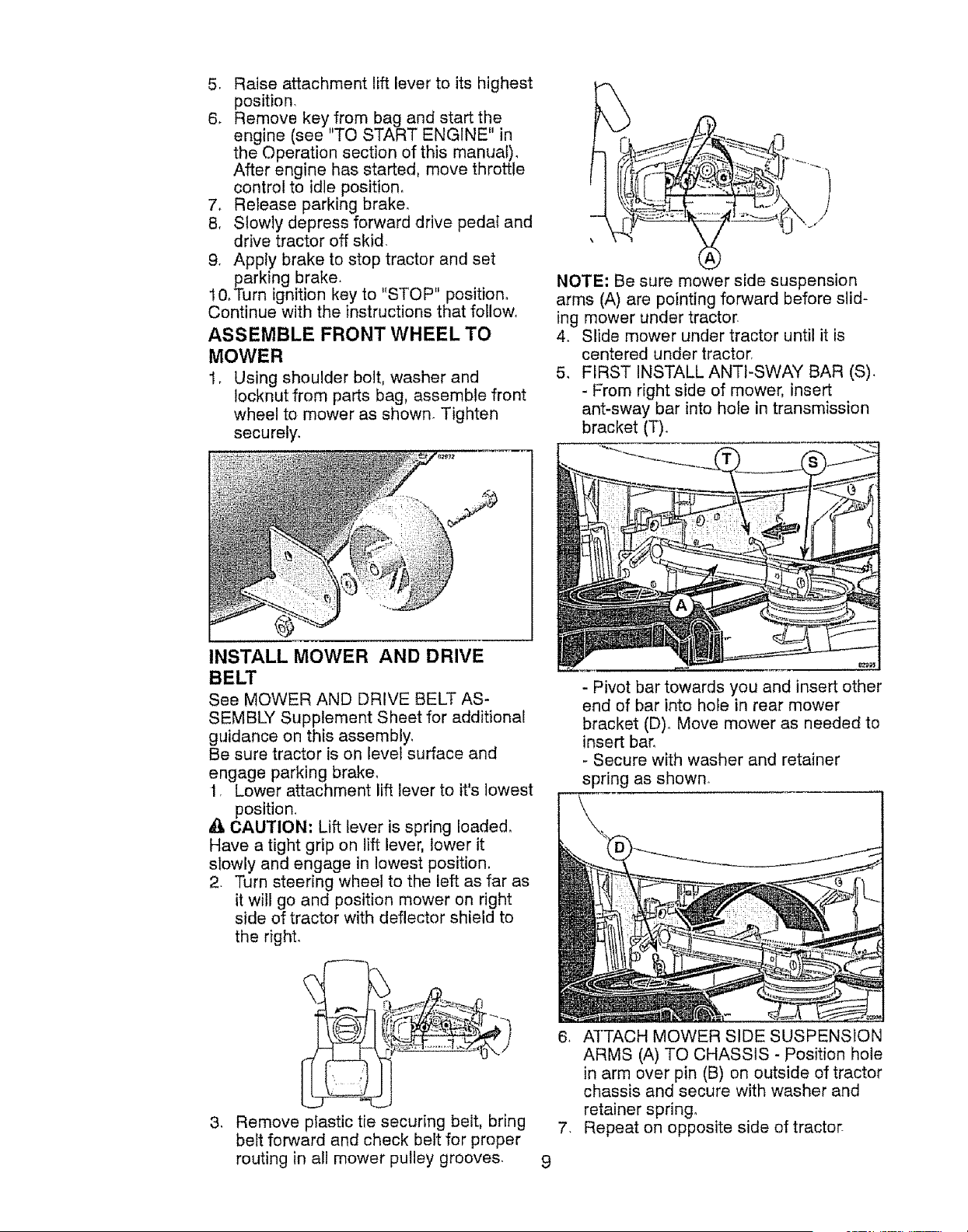
ASSEMBLE FRONT WHEEL TO
MOWER
1, Using shoulder bolt, washer and
locknut from parts bag, assemble front
wheel to mower as shown. Tighten
securely.
NOTE: Be sure mower side suspension
arms (A) are pointing forward before slid-
ing mower under tractor,
4, Slide mower under tractor until it is
centered under tractor,
5, FIRST INSTALL ANTI-SWAY BAR (S),
- From right side of mower, insert
ant-sway bar into hole in transmission
bracket (T),
INSTALL MOWER AND DRIVE
BELT
See MOWER AND DRIVE BELT AS-
SEMBLY Supplement Sheet for additional
guidance on this assembly,
Be sure tractor is on level surface and
engage parking brake,
1, Lower attachment lift lever to it's lowest
position_
CAUTION: Lift lever is spring loaded.
Have a tight grip on lift lever, lower it
slowly and engage in lowest position.
2. Turn steering wheel to the left as far as
it will go and position mower on right
side of tractor with deflector shield to
the right,
3_
6_
Remove plastic tie securing belt. bring 7,
belt forward and check belt for proper
routing in all mower pulley grooves. 9
- Pivot bar towards you and insert other
end of bar into hole in rear mower
bracket (D)o Move mower as needed to
insert bar_
- Secure with washer and retainer
spring as shown.
ATTACH MOWER SIDE SUSPENSION
ARMS (A) TO CHASSIS - Position hole
in arm over pin (B) on outside of tractor
chassis and secure with washer and
retainer spring,
Repeat on opposite side of tractor-
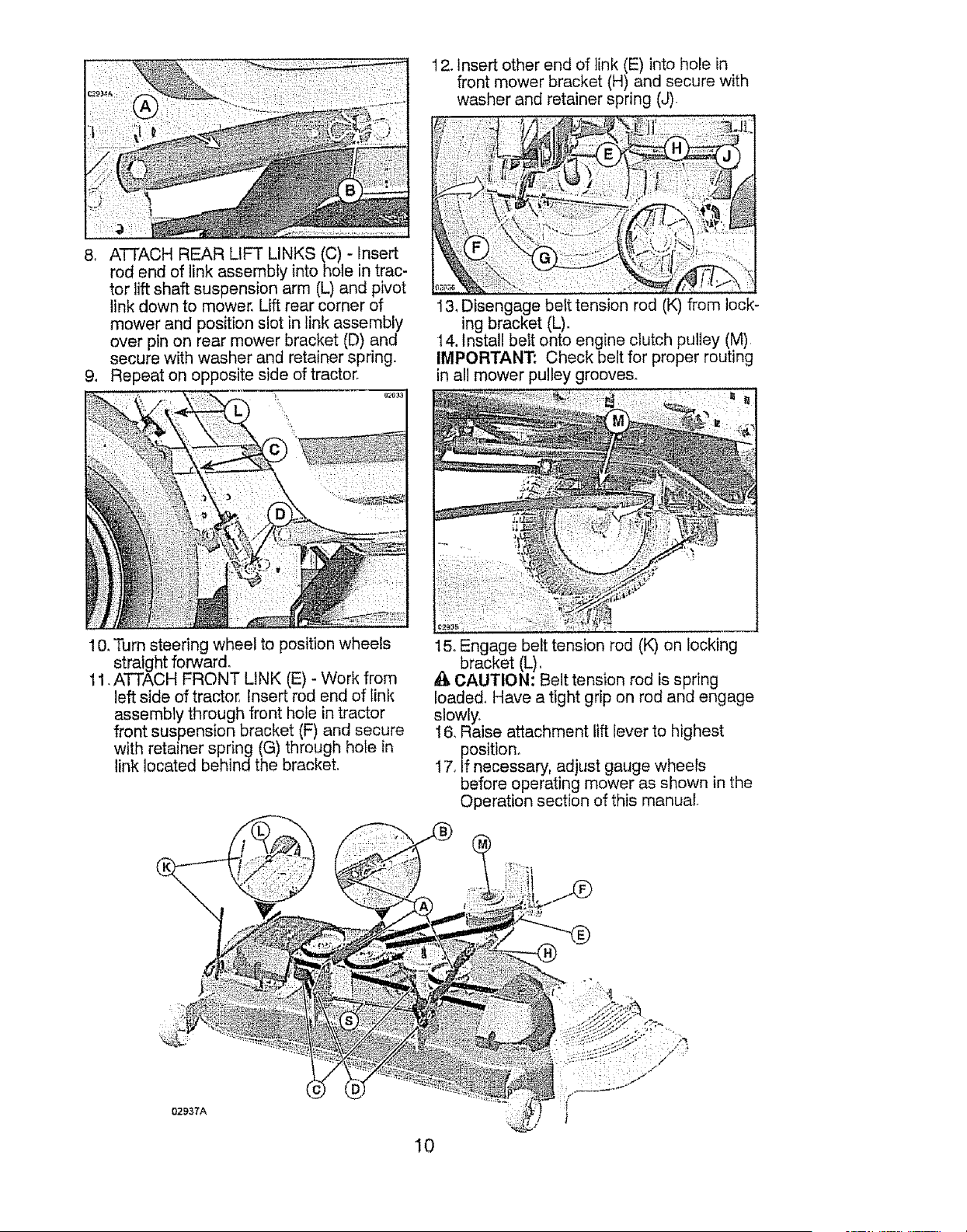
12.Insertotherendof link(E)intoholein
frontmowerbracket(H)andsecurewith
washerandretainerspring(J)
8, ATTACHREARUFT LINKS(C)- Insert
rodendof linkassemblyintoholein trac-
tor liftshaftsuspensionarm(L)andpivot
linkdownto mowerLiftrearcornerof
mowerandpositionslot in linkassembly
overpinon rearmowerbracket(D)and
securewithwasherandretainerspring.
9. Repeaton oppositesideoftractor.
13_Disengage belt tension rod (K) from lock-
ing bracket (L)_
14. Install belt onto engine clutch pulley (M).
IMPORTANT: Check belt for proper routing
in all mower pulley grooves.
10. Turn steering wheel to position wheels
straight forward.
11. ATTACH FRONT LINK (E) - Work from
left side of tractor, Insert rod end of tink
assembly through front hole in tractor
front suspension bracket (F) and secure
with retainer spring (G) through hole in
link located behind the bracket.
15. Engage belt tension rod (K) on locking
. bracket (L).
CAUTION: Belt tension rod is spring
loaded. Have a tight grip on rod and engage
slowly.
16, Raise attachment lift lever to highest
position.
17. [f necessary, adjust gauge wheels
before operating mower as shown in the
Operation section of this manual.
02937A
10
CHECK TIRE PRESSURE
The tires on your tractor were overinflated
at the factory for shipping purposes_ Cor-
rect tire pressure is important for best
cutting performance.
• Reduce tire pressure to PS1 shown on
tire&
CHECK DECK LEVELNESS
For best cutting results, mower hous-
ing should be properly leveled. See "TO
LEVEL MOWER" in the Service and
Adjustments section of this manual.
CHECK FOR PROPER POSITION
OF ALL BELTS
See the figures that are shown for replac-
ing motion and mower blade drive belts
in the Service and Adjustments section
of this manual. Verify that the belts are
routed correctly.
CHECK BRAKE SYSTEM
After you learn how to operate your trac-
tor, check to see that the brake is operat-
ing properly. See "TO CHECK BRAKE"
in the Service and Adjustments section of
this manual.
v'CHECKLIST
Before you operate your new tractor, we
wish to assure that you receive the best
performance and satisfaction from this
Quality Product°
Please review the following checklist:
J All assembly instructions have been
completed,
v" No remaining loose parts in carton.
J Battery is properly prepared and
charged.
v" Seat is adjusted comfortably and tight-
ened securely_
v" All tires are properly inflated_ (For ship-
ping purposes, the tires were overin-
fiated at the factory).
v" Be sure mower deck is properly leveled
side-to-side/front-to-rear for best cutting
results. (Tires must be properly inflated
for leveling).
¢" Check mower and drive belts Be sure
they are routed properly around pulleys
andinside all belt keepers.
v" Check wiring. See that all connections
are still secure and wires are properly
clamped.
J" Before driving tractor, be sure freewheel
control is in "transmission engaged"
position (see "TO TRANSPORT" in the
Operation section of this manual).
While learning how to use your tractor,
pay extra attention to the following impor-
tant items:
J Engine oil is at proper level.
,/' Fuel tank is filled with fresh, clean,
regular unleaded gasoline.
,/Become familiar with all controls, their
location and function. Operate them
before you start the engine
v" Be sure brake system is in safe operat-
ing condition_
v" Be sure Operator Presence System
and Reverse Operation System (ROS)
are working properly (See the Opera-
tion and Maintenance sections in this
manual).
J It is important to purge the transmission
before operating your tractor for the first
time. Follow proper starting and transmis-
sion purging instructions (See "TO START
ENGINE" and "PURGE TRANSMISSION"
in the Operation section of this manual).
11
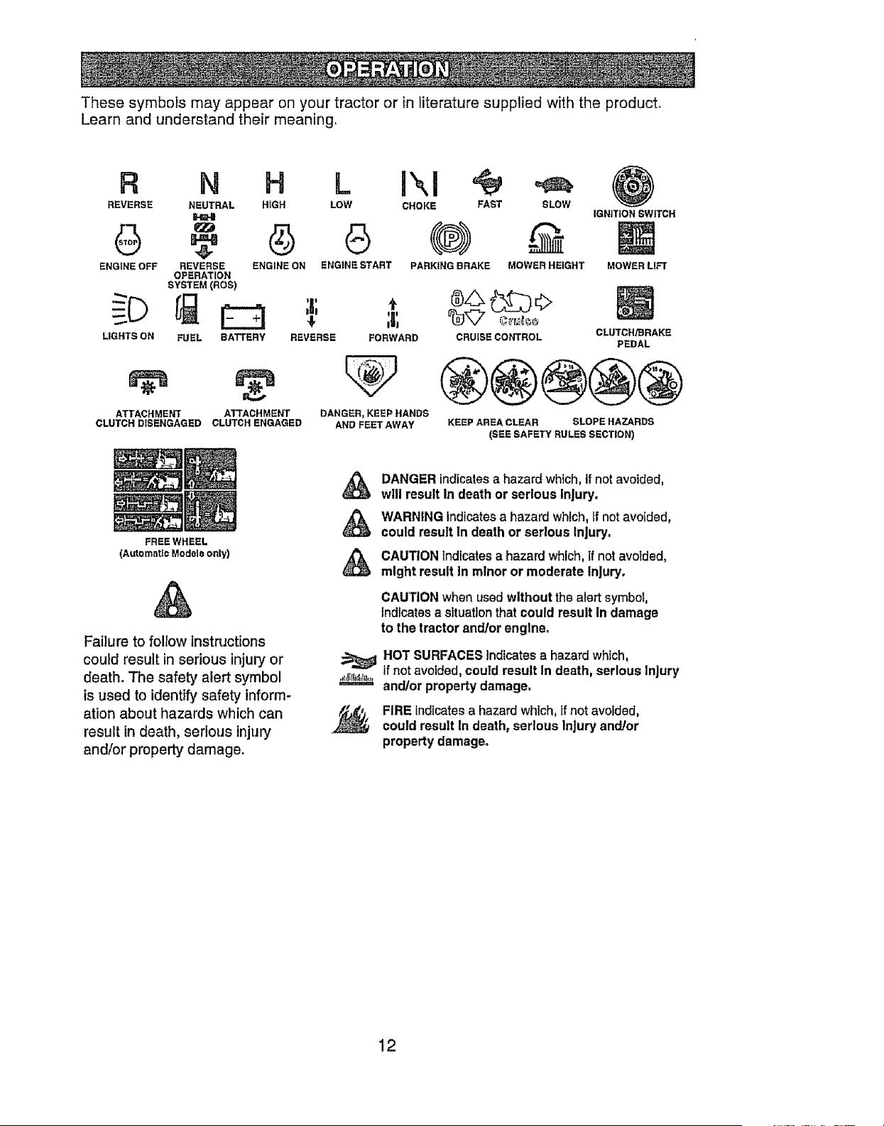
These symbols may appear on your tractor or in literature supplied with the product.
Learn and understand their meaning.
R N H
REVERSE NEUTRAL HIGH
ENGINE OFF REVERSE ENGINE ON
OPERATION
SYSTEM (ROS)
LIGHTS ON FUEL BATTERY
ATTACHMENT ATTACHMENT
CLUTCH DISENGAGED CLUTCH ENGAGED
FREE WHEEL
(Automatic Models only)
Failure to follow instructions
could result in serious injury or
death. The safety alert symbol
is used to identify safety inform-
ation about hazards which can
result in death, serious injury
and/or property damage.
LOW CHOKE FAST SLOW
G (@)
ENGINE START PARKING BRAKE MOWER HEIGHT
I
;r
I
REVERSE FORWARD
DANGER, KEEP HANDS
AND FEET AWAY
IGNITION SWITCH
MOWER LIFT
®$
CRUISE CONTROL CLUTCH/BRAKE
PEDAL
@@®@@
KEEP AREA CLEAR SLOPE HAZARDS
(SEE SAFETY RULES SECTION)
_Ib ANGER indicates a hazard which,If not avoided,
will result In death or serious Injury.
WARNING Indicatesa hazard which, tf not avoided,
could result In death or serious Injury,
CAUTION Indicatesa hazard which, if not avoided,
might result In mtnor or moderate Injury.
CAUTION when usedwithout the alert symbol,
indicates a situationthat could result In damage
to the tractor andlor engine,
HOT SURFACES Indicates a hazard which,
If not avoided, could result In death, serious Injury
and/or property damage.
FIRE Indicatesa hazard which,If not avoided,
could result In death, serious Injury and/or
property damage,
12
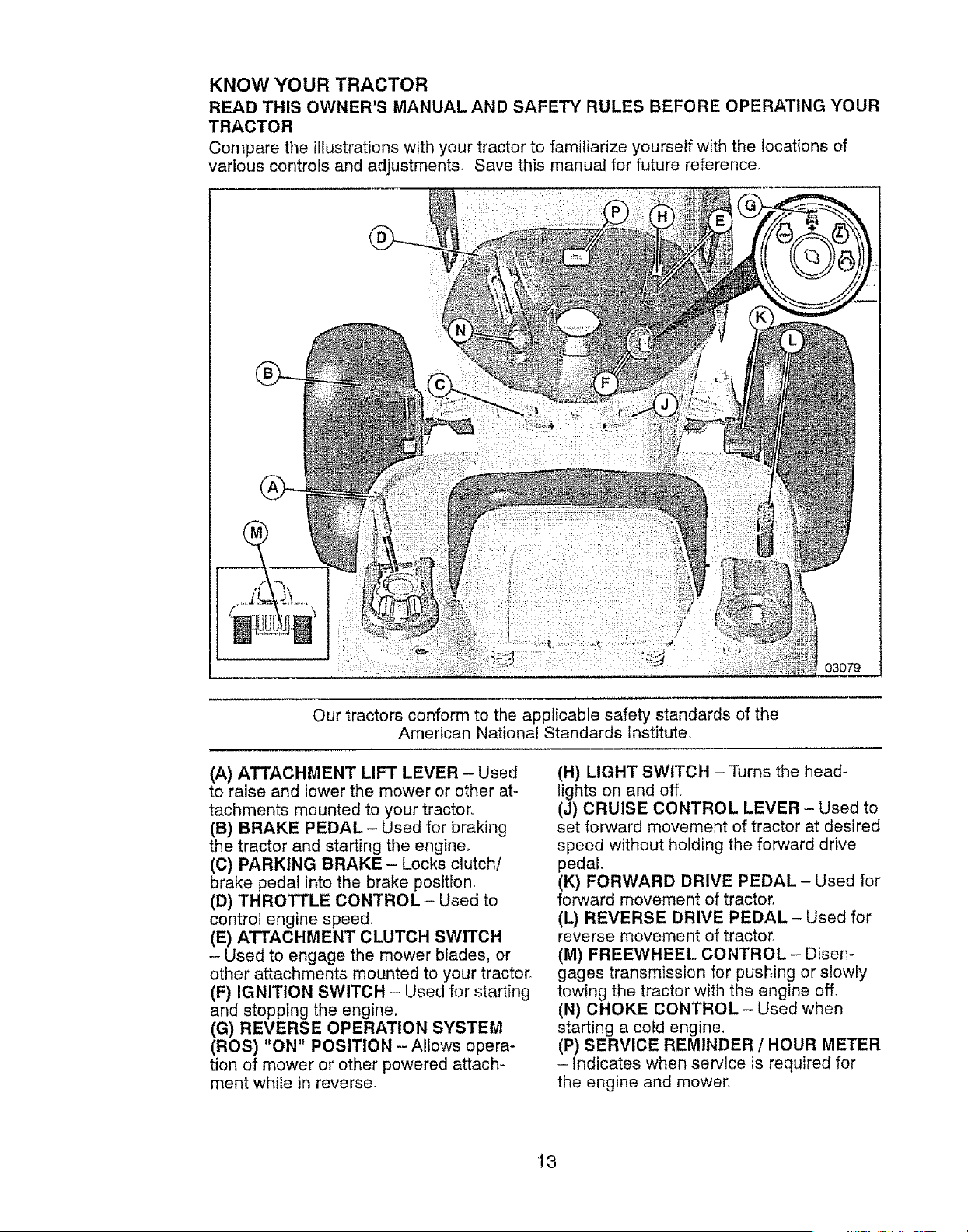
KNOW YOUR TRACTOR
READ THIS OWNER'S MANUAL AND SAFETY RULES BEFORE OPERATING YOUR
TRACTOR
Compare the illustrations with your tractor to familiarize yourself with the locations of
various controls and adjustments. Save this manual for future reference,
i
03079
Our tractors conform to the applicable safety standards of the
American National Standards institute,
(A) ATTACHMENT LIFT LEVER - Used
to raise and lower the mower or other at-
tachments mounted to your tractor,
(B) BRAKE PEDAL- Used for braking
the tractor and starting the engine°
(C) PARKING BRAKE - Locks clutch/
brake pedal into the brake position.
(D) THROTTLE CONTROL - Used to
control engine speed.
(E) ATTACHMENT CLUTCH SWITCH
- Used to engage the mower bfades, or
other attachments mounted to your tractor.
(F) IGNITION SWITCH - Used for starting
and stopping the engine.
(G) REVERSE OPERATION SYSTEM
(ROS) "ON" POSITION -Allows opera-
tion of mower or other powered attach-
ment while in reverse,
(H) LIGHT SWITCH - Turns the head-
lights on and off,
(J) CRUISE CONTROL LEVER - Used to
set forward movement of tractor at desired
speed without holding the forward drive
pedal
(K) FORWARD DRIVE PEDAL- Used for
forward movement of tractor.
(L) REVERSE DRIVE PEDAL- Used for
reverse movement of tractor.
(M) FREEWHEEL CONTROL- Disen-
gages transmission for pushing or slowfy
towing the tractor with the engine off,
(N) CHOKE CONTROL- Used when
starting a cold engine.
(P) SERVICE REMINDER / HOUR METER
- Indicates when service is required for
the engine and mower,
t3
The operation of any tractor can result in foreign objects thrown into the
eyes, which can result in severe eye damage. Always wear safety glasses
or eye shields while operating your tractor or performing any adjustments
or repairs, We recommend standard safety glasses or a wide vision safety
mask worn over spectacles.
HOW TO USE YOUR TRACTOR
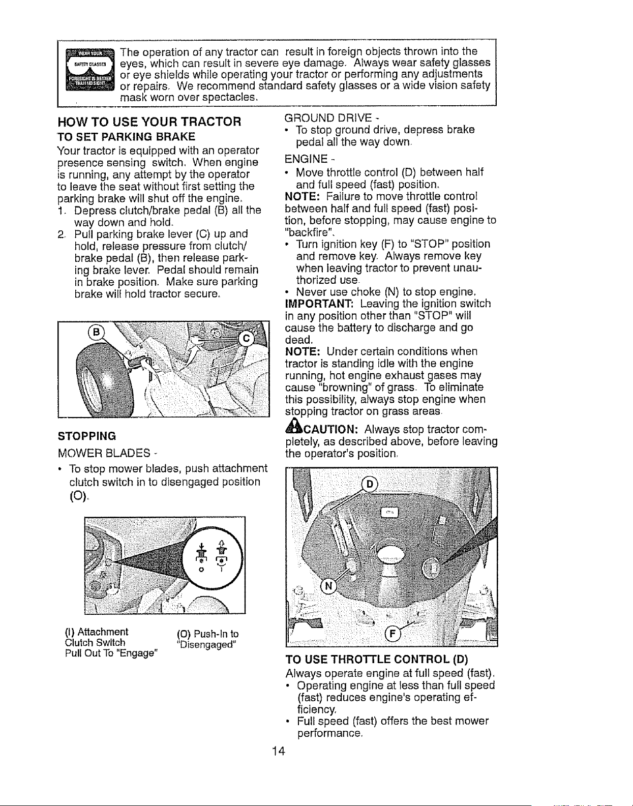
TO SET PARKING BRAKE
Your tractor is equipped with an operator
presence sensing switch, When engine
is running, any attempt by the operator
to leave the seat without first setting the
parking brake will shut off the engine,
1. Depress clutch/brake pedal (B) all the
way down and hold.
2, Pull parking brake lever (C) up and
hold, release pressure from clutch/
brake pedal (B), then release park-
ing brake lever. Pedal should remain
in brake position. Make sure parking
brake will hold tractor secure.
STOPPING
MOWER BLADES -
• To stop mower blades, push attachment
clutch switch in to disengaged position
(o).
(1) Attachment (0) Push-ln to
Clutch Switch "Disengaged"
Pull Out To "Engage"
GROUND DRIVE -
• To stop ground drive, depress brake
pedal all the way down.
ENGINE °
• Move throttle control (D) between half
and full speed (fast) position.
NOTE: Failure to move throttle control
between half and full speed (fast) posi-
tion, before stopping, may cause engine to
"backfire".
• Turn ignition key (F) to "STOP" position
and remove key. Always remove key
when leaving tractor to prevent unau-
thorized use.
• Never use choke (N) to stop engine.
IMPORTANT: Leaving the ignition switch
in any position other than "STOP" will
cause the battery to discharge and go
dead,
NOTE: Under certain conditions when
tractor is standing idle with the engine
running, hot engine exhaust gases may
cause "browning" of grass. To eliminate
this possibility, always stop engine when
stopping tractor on grass areas.
_IbCAUTION: Always stop tractor com-
pletely, as described above, before leaving
the operator's position.
TO USE THROTTLE CONTROL (D)
Always operate engine at full speed (fast),
• Operating engine at tess than full speed
(fast) reduces engine's operating ef-
ficiency,
. Full speed (fast) offers the best mower
performance.
14
TO USE THROTTLE CONTROL (D)
Always operate engine at full speed (fast),
• Operating engine at less than full speed
(fast) reduces engine's operating ef-
ficiency_
• Full speed (fast) offers the best mower
performance.
TO USE CHOKE CONTROL (N)
Use choke control whenever you are start-
ing a cold engine. Do not use to start a
warm engine.
• To engage choke control, pull knob out
Slowly push knob in to disengage.
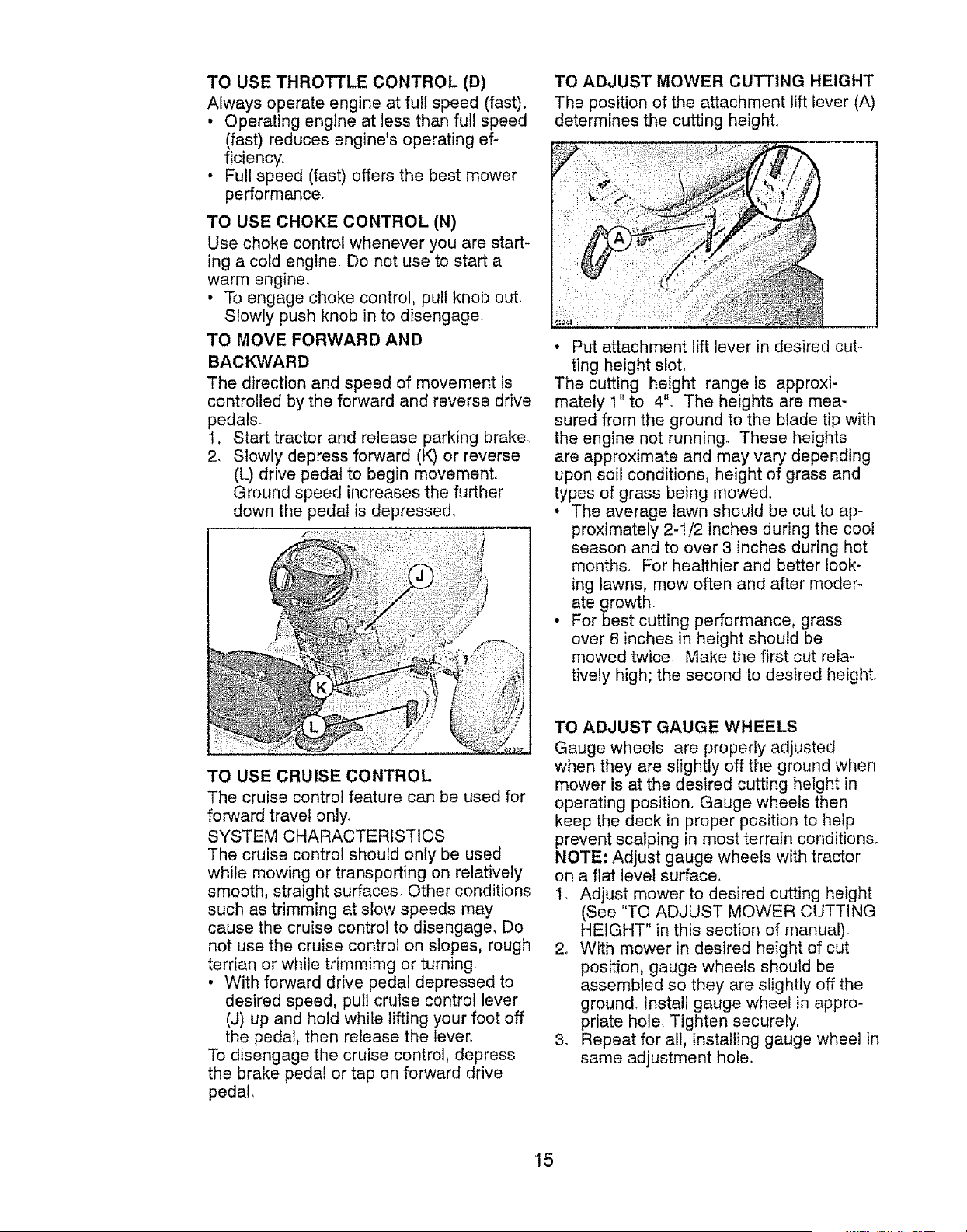
TO MOVE FORWARD AND
BACKWARD
The direction and speed of movement is
controlled by the forward and reverse drive
pedals.
1, Start tractor and release parking brake.
2. Slowly depress forward (K) or reverse
(L) drive pedal to begin movement.
Ground speed increases the further
down the pedal is depressed.
_!}i/
L
TO USE CRUISE CONTROL
The cruise control feature can be used for
forward travel only.
SYSTEM CHARACTERISTICS
The cruise control should only be used
while mowing or transporting on relatively
smooth, straight surfaces. Other conditions
such as trimming at slow speeds may
cause the cruise control to disengage, Do
not use the cruise control on slopes, rough
terrian or while trimmimg or turning
• With forward drive pedal depressed to
desired speed, pull cruise control lever
(J) up and hold white lifting your foot off
the pedal, then release the lever,
To disengage the cruise control, depress
the brake pedal or tap on forward drive
pedal_
TO ADJUST MOWER CUTTING HEIGHT
The position of the attachment lift lever (A)
determines the cutting height,
• Put attachment lift lever in desired cut-
ting height slot.
The cutting height range is approxi-
mately 1" to 4". The heights are mea-
sured from the ground to the blade tip with
the engine not running° These heights
are approximate and may vary depending
upon soil conditions, height of grass and
types of grass being mowed.
• The average lawn should be cut to ap-
proximately 2-1/2 inches during the coo!
season and to over 3 inches during hot
months. For healthier and better look-
ing lawns, mow often and after moder-
ate growth.
• For best cutting performance, grass
over 6 inches in height should be
mowed twiCer Make the first cut rela-
tively high; the second to desired height.
TO ADJUST GAUGE WHEELS
Gauge wheels are properly adjusted
when they are slightly off the ground when
mower is at the desired cutting height in
operating position. Gauge wheels then
keep the deck in proper position to help
prevent scalping in most terrain conditions.
NOTE: Adjust gauge wheels with tractor
on a flat level surface,
I. Adjust mower to desired cutting height
(See "TO ADJUST MOWER CUTTING
HEIGHT" in this section of manual)
2. With mower in desired height of cut
position, gauge wheels should be
assembled so they are slightly off the
ground. Install gauge wheel in appro-
priate hole. Tighten securely,
3. Repeat for all, installing gauge wheel in
same adjustment hole.
15
9/16
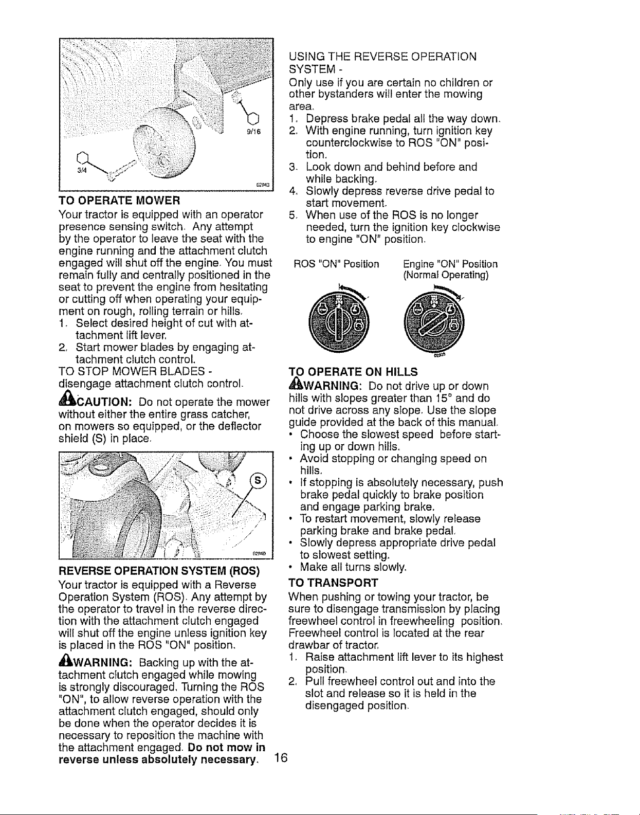
TO OPERATE MOWER
Your tractor is equipped with an operator
presence sensing switch. Any attempt
by the operator to leave the seat with the
engine running and the attachment clutch
engaged witl shut off the engine. You must
remain fully and centrally positioned in the
seat to prevent the engine from hesitating
or cutting off when operating your equip-
ment on rough, rolling terrain or hills.
1. Select desired height of cut with at-
tachment lift lever,
2, Start mower blades by engaging at-
tachment clutch control.
TO STOP MOWER BLADES -
disengage attachment clutch control.
_IbCAUTION: Do not operate the mower
without either the entire grass catcher,
on mowers so equipped, or the deflector
shield (S) in place.
REVERSE OPERATION SYSTEM (ROS)
Your tractor is equipped with a Reverse
Operation System (ROS)_ Any attempt by
the operator to travel in the reverse direc-
tion with the attachment clutch engaged
wilt shut off the engine unless ignition key
is placed in the ROS "ON" position.
A_,WARNING: Backing up with the at-
tachment clutch engaged while mowing
is strongly discouraged, Turning the ROS
"ON", to allow reverse operation with the
attachment clutch engaged, should only
be done when the operator decides it is
necessary to reposition the machine with
the attachment engaged. Do not mow in
reverse unless absolutely necessary,
USING THE REVERSE OPERATION
SYSTEM -
Only use if you are certain no children or
other bystanders witl enter the mowing
area.
t, Depress brake pedal all the way down.
2. With engine running, turn ignition key
counterclockwise to ROS "ON" posi-
tion,
3. Look down and behind before and
while backing_
4_ Slowly depress reverse drive pedal to
start movement,
5. When use of the ROS is no longer
needed, turn the ignition key clockwise
to engine "ON" position.
ROS "ON" Position
Engine "ON" Position
(Normal Operating)
PERATE ON HILLS
ARNING: Do not drive up or down
hills with slopes greater than 15 ° and do
not drive across any stope, Use the slope
guide provided at the back of this manual.
• Choose the slowest speed before start-
ing up or down hills.
. Avoid stopping or changing speed on
hills°
. If stopping is absolutely necessary, push
brake pedal quickly to brake position
and engage parking brake.
• To restart movement, slowly release
parking brake and brake pedal,
• Slowly depress appropriate drive pedal
to slowest setting.
• Make all turns slowly,
TO TRANSPORT
When pushing or towing your tractor, be
sure to disengage transmission by placing
freewheel control in freewheeling position,
Freewheel control is located at the rear
drawbar of tractor.
1. Raise attachment lift lever to its highest
position,
2, Pull freewheel control out and into the
slot and release so it is held in the
disengaged position.
'16
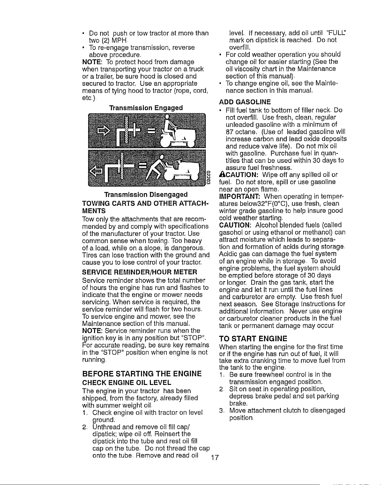
• Do not push or tow tractor at more than
two (2) MPH
• To re-engage transmission, reverse
above procedure,
NOTE: To protect hood from damage
when transporting your tractor on a truck
or a trailer, be sure hood is closed and
secured to tractor, Use an appropriate
means of tying hood to tractor (rope, cord,
etc.).
Transmission Engaged
Transmission Disengaged
TOWING CARTS AND OTHER ATTACH-
MENTS
Tow only the attachments that are recom-
mended by and comply with specifications
of the manufacturer of your tractor, Use
common sense when towing. Too heavy
of a load, while on a slope, is dangerous.
Tires can lose traction with the ground an d
cause you to lose control of your tractor,
SERVICE REMINDER/HOUR METER
Service reminder shows the total number
of hours the engine has run and flashes to
indicate that the engine or mower needs
servicing, When service is required, the
service reminder will flash for two hours.
To service engine and mower, see the
Maintenance section of this manual,
NOTE: Service reminder runs when the
ignition key is in any position but "STOP".
For accurate reading, be sure key remains
in the "STOP" position when engine is not
running,
BEFORE STARTING THE ENGINE
CHECK ENGINE OIL LEVEL
The engine in your tractor has been
shipped, from the factory, already filled
with summer weight oil.
1. Check engine oil with tractor on level
ground.
2. Unthread and remove oil fill cap/
dipstick; wipe oil off. Reinsert the
dipstick into the tube and rest oil fil!
cap on the tube. Do not thread the cap
onto the tube. Remove and read oil 17
level. If necessary, add oil until "FULL['
mark on dipstick is reached. Do not
overfirt,
For cold weather operation you should
change oil for easier starting (See the
oil viscosity chart in the Maintenance
section of this manual).
To change engine oil, see the Mainte-
nance section in this manual.
ADD GASOLINE
• Fill fuel tank to bottom of filler neck. Do
not overfill. Use fresh, clean, regular
unleaded gasoline with a minimum of
87 octane, (Use of leaded gasoline will
increase carbon and lead oxide deposits
and reduce valve life). Do net mix oil
with gasoIine. Purchase fuel in quan-
tities that can be used within 30 days to
assure fuel freshness.
_CAUTION: Wipe off any spilled oil or
fuel. Do not store, spill or use gasoline
near an open flame.
IMPORTANT: When operating in temper-
atures below32°F(0°C), use fresh, clean
winter grade gasoline to help insure good
cold weather starting.
CAUTION: Alcohol blended fuels (called
gasohol or using ethanol or methanol) can
attract moisture which leads to separa-
tion and formation of acids during storage
Acidic gas can damage the fuel system
of an engine while in storage. To avoid
engine problems, the fuel system should
be emptied before storage of 30 days
or longer, Drain the gas tank, start the
engine and let it run until the fuel lines
and carburetor are empty, Use fresh fuel
next season, See Storage Instructions for
additional information, Never use engine
or carburetor cleaner products in the fuel
tank or permanent damage may occur.
TO START ENGINE
When starting the engine for the first time
or if the engine has run out of fuel, it will
take extra cranking time to move fuel from
the tank to the engine.
1_ Be sure freewheel control is in the
transmission engaged position,
2- Sit on seat in operating position,
depress brake pedal and set parking
brake.
3. Move attachment clutch to disengaged
position.
4. Movethrottlecontrolto fast position
5. Pullchokecontrolout for a colden-
ginestart attempt,Fora warmengine
start attemptthe chokecontrolmay
notbe needed.
NOTE;Beforestarting,readthewarm
andcoldstartingproceduresbelow.
6, Insertkey into ignitionandturn key
clockwiseto start positionand release
keyas soonas enginestarts,Do not
runstartercontinuouslyfor morethan
fifteensecondsper minute.If the
engine does not start after several
attempts, push choke control in, wait
a few minutes and try again° tf engine
still does not start, pull the choke con-
trol out and retry,
WARM WEATHER STARTING (50 ° F and
above)
7. When engine starts, stowly push
choke control in until the engine
begins to run smoothly. If the engine
starts to run roughly, pull the choke
control out slightly for a few seconds
and then continue to push the control
in slowly_
* The attachments and ground drive can
now be used. If the engine does not
accept the load, restart the engine and
allow it to warm up for one minute using
the choke as described above,
COLD WEATHER STARTING (50 ° F and
below)
7. When engine starts, slowly push
choke control in until the engine
begins to run smoothly, Continue to
push the choke control in small steps
allowing the engine to accept small
changes in speed and load, until the
choke control is fully in, If the engine
starts to run roughly, pull the choke
control out slightly for a few seconds
and then continue to push the control
in slowly, This may require an engine
warm-up period from several seconds
to several minutes, depending on the
temperature.
AUTOMATIC TRANSMISSION WARM
UP
Before driving the unit in cold weather,
the transmission should be warmed up as
follows:
1. Be sure the tractor is on level ground°
2. Release the parking brake and let the
brake slowly return to operating posi-
tion.
3. Allow one minute for transmission to
warm up. This can be done during the
engine warm up period
° The attachments can be used during
the engine warm-up period after the
transmission has been warmed up and
may require the choke control be pulled
out slightly.
NOTE: If at a high altitude (above 3000
feet) or in cold temperatures (below 32 F)
the carburetor fuel mixture may need to
be adjusted for best engine performance
(see "TO ADJUST CARBURETOR" in the
Service and Adjustments section of this
manual),
PURGE TRANSMISSION
_,CAUTION: Never engage or dis-
engage freewheel lever while the engine
is running.
To ensure proper operation and per-
formance, it is recommended that the
transmission be purged before operating
tractor for the first time This procedure will
remove any trapped air inside the trans-
mission which may have developed during
shipping of your tractor,
IMPORTANT: Should your transmission
require removal for service or replace-
ment, it should be purged after reinstall-
ation before operating the tractor.
1. Place tractor safely on a level surface
- that is clear of objects and open - with
engine off and parking brake set
2° Disengage transmission by placing
freewheel control in disengaged posF
tion (See "TO TRANSPORT" in this
section of manual).
3° Sitting in the tractor seat, start engine
After the engine is running, move
throttle control to slow position. Disen-
_gage parking brake.
AUTtON: At any time, during step
4, there may be movement of the drive
wheels.
4. Depress forward drive pedal to full
forward position and hold for five (5)
seconds and release pedal. Depress
reverse drive pedal to full reverse posi-
tion and hold for five (5) seconds and
release pedal, Repeat this procedure
three (3) times.
5. Shutoff engine and set parking brake.
6, Engage transmission by placing free-
wheel control in engaged position (See
"TO TRANSPORT" in this section of
manual),
18
7. Sitting in the tractor seat, start engine,
After the engine is running, move
throttle control to half (1/2) speed,
Disengage parking brake.
& Drive tractor forward for approximately
five feet then backwards for five feet,
Repeat this driving procedure three
times,
Your transmission is now purged and now
ready for normal operation_
MOWING TIPS
• Tire chains cannot be used when the
mower housing is attached to tractor,
• Mower should be properly leveled for
best mowing performance, See "TO
LEVEL MOWER HOUSING" in the
Service and Adjustments section of this
manual.
• The left hand side of mower should be
used for trimming.
• Drive so that clippings are discharged
onto the area that has already been
cut, Have the cut area to the right of
the tractor, This will result in a more
even distribution of clippings and more
uniform cutting.
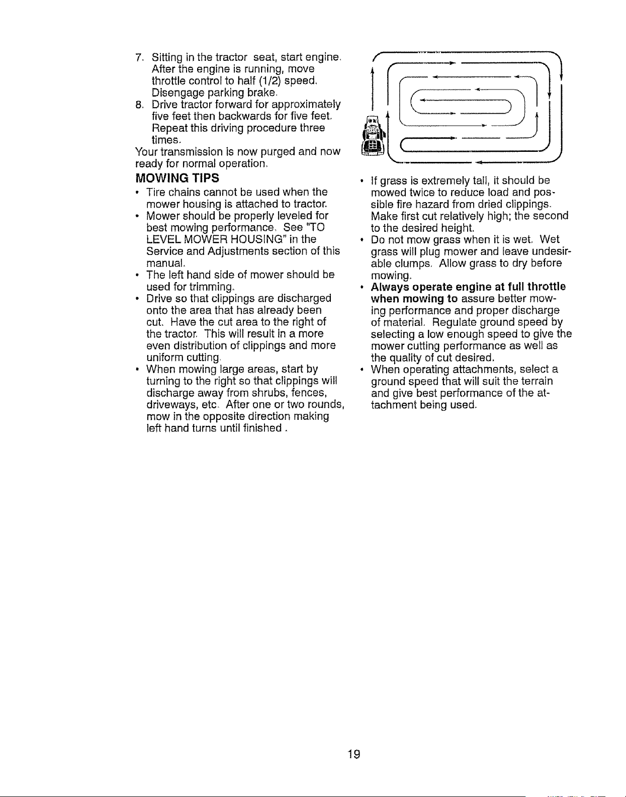
• When mowing large areas, start by
turning to the right so that clippings wiil
discharge away from shrubs, fences,
driveways, etc. After one or two rounds,
mow in the opposite direction making
left hand turns until finished.
f
tL( _ J
• If grass is extremely tall, it should be
mowed twice to reduce load and pos-
sible fire hazard from dried clippings.
Make first cut relatively high; the second
to the desired height.
• Do not mow grass when it is weL Wet
grass will plug mower and leave undesir-
able clumps, Allow grass to dry before
mowing.
• Always operate engine at full throttle
when mowing to assure better mow-
ing performance and proper discharge
of material. Regulate ground speed by
selecting a low enough speed to give the
mower cutting performance as wen as
the quality of cut desire&
• When operating attachments, select a
ground speed that will suit the terrain
and give best performance of the at-
tachment being used.
19
, ,,, ,,,, , .....
MAINTENANCE
SCHEDULE
Check Brake..0peratien
.3heck Tire Pressure
T_ .......
iCheck Opecal_i Pt_,_,_e_l_a _ ROB gyr, l_rn_
A 3heck r Loose Fasteners
C 3heck/Re_.!ace Mower Blades
"] .ubri_:ation Chart
0 3heck Battery Level
R 31ear atlery end Terminais
_,heck Transex_e €o_!!ng
3beck Mower Levelness
3hack V-Belts
3heck Eng!ne Oi{ Level
3han,qe Engine Oil (with ofl filter}
3baRge Eogine Oil (wilhout ell tiller
E 31ean A!r Filter .......
G 3!ear Air Screen
| inspec! Muffler/Spark Arrester
U RePlace Oil Filter (I! equipped)
E Clean En,_ine Cooling Fins
Replace Spark Plug
Replace Air Filler paper Cartridge
Replace Fuel Filter
BEFORE EVERY
EACH 8
USE HOURS
v" v
v" e," .........
v'
1 - Change mere oen when operatfnp under a heavy load or
tn high ambfent lempsfaleres
2 - Service more often when oparaling in dirty of dusty conditions
EVERY EVERY EVERY EVEeY BEFORE
25 50 t{](_ SEASON STORAGE
HOURS HOURS HOURS
= n == n,= H,,
v" _"
V%
v" v' .....
V' .....................V'
J
V'
v"
V"
V'
_ v
v"
3 * Replace blades mere ellen when mewing in sandy solt
4 - Not required ff equipped w{th meinlenance4ree battery
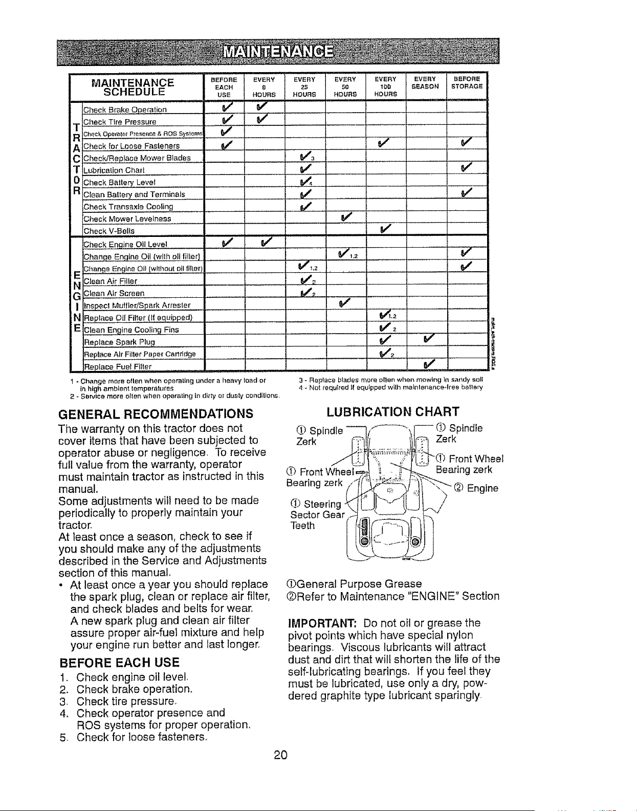
GENERAL RECOMMENDATIONS
The warranty on this tractor does not
cover items that have been subjected to
operator abuse or negligence. To receive
full value from the warranty, operator
must maintain tractor as instructed in this
manual,
Some adjustments will need to be made
periodically to properly maintain your
tractor.
At least once a season, check to see if
you should make any of the adjustments
described in the Service and Adjustments
section of this manual
• At least once a year you should replace
the spark plug, clean or replace air filter,
and check blades and belts for wear.
A new spark plug and clean air filter
assure proper air-fuel mixture and help
your engine run better and last longer.
BEFORE EACH USE
1. Check engine oil level.
2. Check brake operation_
3. Checktire pressure.
4o Check operator presence and
ROS systems for proper operation.
5 Check for loose fasteners.
LUBRICATION CHART
(I) St _f---_ Spindle
Zerk Zerk
Front Wheel
(,# Bearing zerk
Bearing zerk
Engine
d) Steerin(
Sector Gear
Teeth
OGeneral Purpose Grease
@Refer to Maintenance "ENGINE" Section
IMPORTANT: Do not oi! or grease the
pivot points which have special nylon
bearings. Viscous lubricants will attract
dust and dirt that will shorten the life of the
selfqubricating bearings. If you feel they
must be lubricated, use only a dry, pow-
dered graphite type lubricant sparingly
20
TRACTOR
Always observe safety rules when per-
forming any maintenance_
BRAKE OPERATION
If tractor requires more than five (5) feet to
stop at highest speed in highest gear on a
level, dry concrete er paved surface, then
brake must be serviced. (See "TO CHECK
BRAKE" in the Service and Adjustments
section of this manual).
TIRES
• Maintain proper air pressure in all tires
(See PSI on tires).
• Keep tires free of gasoline, oil, or insect
control chemicals which can harm rub-
ber.
• Avoid stumps, stones, deep ruts, sharp
objects and other hazards that may
cause tire damage.
NOTE: To seal tire punctures and prevent
flat tires due to slow leaks, tire sealant
may be purchased from your local parts
dealer. Tire sealant also prevents tire dry
rot and corrosion.
OPERATOR PRESENCE SYSTEM AND
REVERSE OPERATION SYSTEM (ROS)
Be sure operator presence and reverse
operation systems are working properly, if
your tractor does not function as de-
scribed, repair the problem immediately,
• The engine should not start unless the
brake pedal is fulty depressed, and the
attachment clutch control is in the disen-
gaged position,
CHECK OPERATOR PRESENCE
SYSTEM
• When the engine is running, any at-
tempt by the operator to leave the seat
without first setting the parking brake
should shut off the engine.
• When the engine is running and the
attachment clutch is engaged, any at-
tempt by the operator to leave the seat
should shut off the engine.
• The attachment clutch should never op-
erate unless the operator is in the seat.
CHECK REVERSE OPERATION (ROS)
SYSTEM
• When the engine is running with the
ignition switch in the engine "ON" posi-
tion and the attachment clutch engaged,
any attempt by the operator to shift into
reverse should shut off the engine.
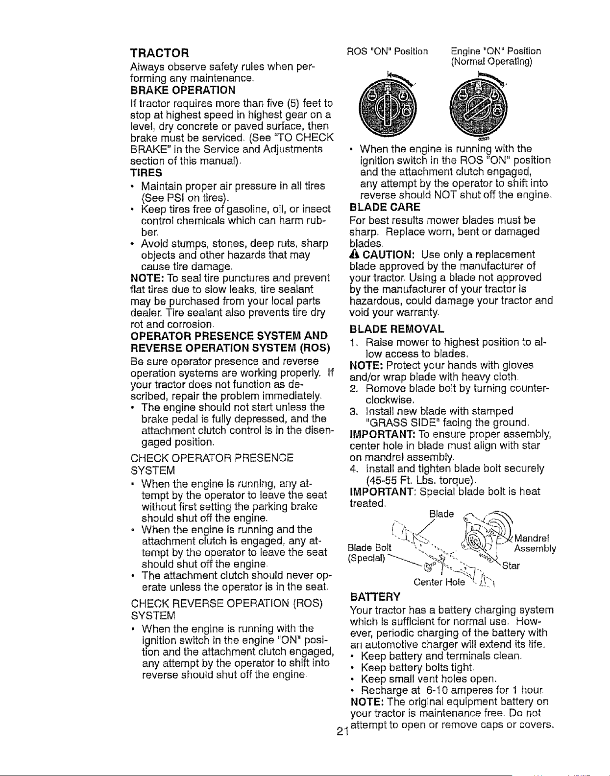
ROS "ON" Position
Engine "ON" Position
(Normal Operating)
21
• When the engine is running with the
ignition switch in the ROS "ON" position
and the attachment clutch engaged,
any attempt by the operator to shift into
reverse should NOT shut off the engine.
BLADE CARE
For best results mower blades must be
sharp. Replace worn, bent or damaged
blades.
_i, CAUTION: Use only a replacement
blade approved by the manufacturer of
your tractor, Using a blade not approved
by the manufacturer of your tractor is
hazardous, could damage your tractor and
void your warranty.
BLADE REMOVAL
1, Raise mower to highest position to al-
low access to blades_
NOTE: Protect your hands with gloves
and/or wrap blade with heavy cloth.
2. Remove blade bolt by turning counter-
clockwise.
& Install new blade with stamped
"GRASS SIDE" facing the ground.
IMPORTANT: To ensure proper assembly,
center hole in blade must align with star
on mandrel assembly.
4_ install and tighten blade bolt securely
(45-55 Ft. Lbs, torque).
IMPORTANT: Special blade bolt is heat
treated.
BIade
Blade Bolt -"!'_"_'"-.
(Special)"-- '<
Mandrel
Assembly
BATTERY
Your tractor has a battery charging system
which is sufficient for normal use. How-
ever, periodic charging of the battery with
an automotive charger will extend its life.
• Keep battery and terminals clean.
• Keep battery bolts tight.
• Keep small vent holes open.
• Recharge at 6-!0 amperes for 1 hour.
NOTE: The original equipment batten/on
your tractor is maintenance free. Do not
attempt to open or remove caps or covers.
Addingor checkinglevelof electrolyteis
notnecessary,
TO CLEANBATTERYAND TERMINALS
Corrosionanddirt on the batteryand
terminalscan causethe batteryto "leak"
power.
1. DisconnectBLACKbatterycablefirst
then RED batterycableand remove
batteryfromtractor.
2, Rinsethe batterywith plainwaterand
dry.
3. Cleanterminalsand batterycableends
with wire brushuntilbright.
4. Coatterminalswith greaseor petro-
leumjelly,
5, Reinstallbattery(See"REPLACING
BATTERY"in the SERVICEANDAD-
JUSTMENTSsectionof this manual).
TRANSAXLECOOLING
The transmission fan and cooling fins
should be kept clean to assure proper
cooling.
Do not attempt to clean fan or transmis-
sion while engine is running or while the
transmission is hot° To prevent possible
damage to seals, do not use high pressure
water or steam to clean transaxle.
• Inspect cooling fan to be sure fan blades
are intact and clean,
. inspect cooling fins for dirt, grass clip-
pings and other materials, To prevent
damage to seals, do not use com-
pressed air or high pressure sprayer to
clean cooling fin&
TRANSAXLE PUMP FLUID
The transaxle was sealed at the factory
and fluid maintenance is not required for
the life of the transaxle_ Should the trans-
axle ever leak or require servicing, contact
your nearest Sears or other qualified
service center.
V-BELTS
Check V-belts for deterioration and wear
after 100 hours of operation and replace
if necessary, The belts are not adjustable,
Replace belts if they begin to slip from
wear.
ENGINE
LUBRICATION
Only use high quality detergent oil rated
with API service classification SG-SL,
Select the oil's SAE viscosity grade
according to your expected operating
temperature,
TEMPEP, ATURIE RANGE ANTICIPATED BEFORE NEXT OIL CHAN6E
olL_m cf_rt_e,
Change the oii after every 50 hours of op-
eration or at least once a year if the tractor
is not used for 50 hours in one year,
Check the crankcase oil level before start-
ing the engine and after each eight (8)
hours of operation.
TO CHANGE ENGINE OIL
Determine temperature range expected
before oil change, All oil must meet API
service classification SG-SL.
• Be sure tractor is on level surface.
• Oil will drain more freely when warm.
• Catch oil in a suitable container.
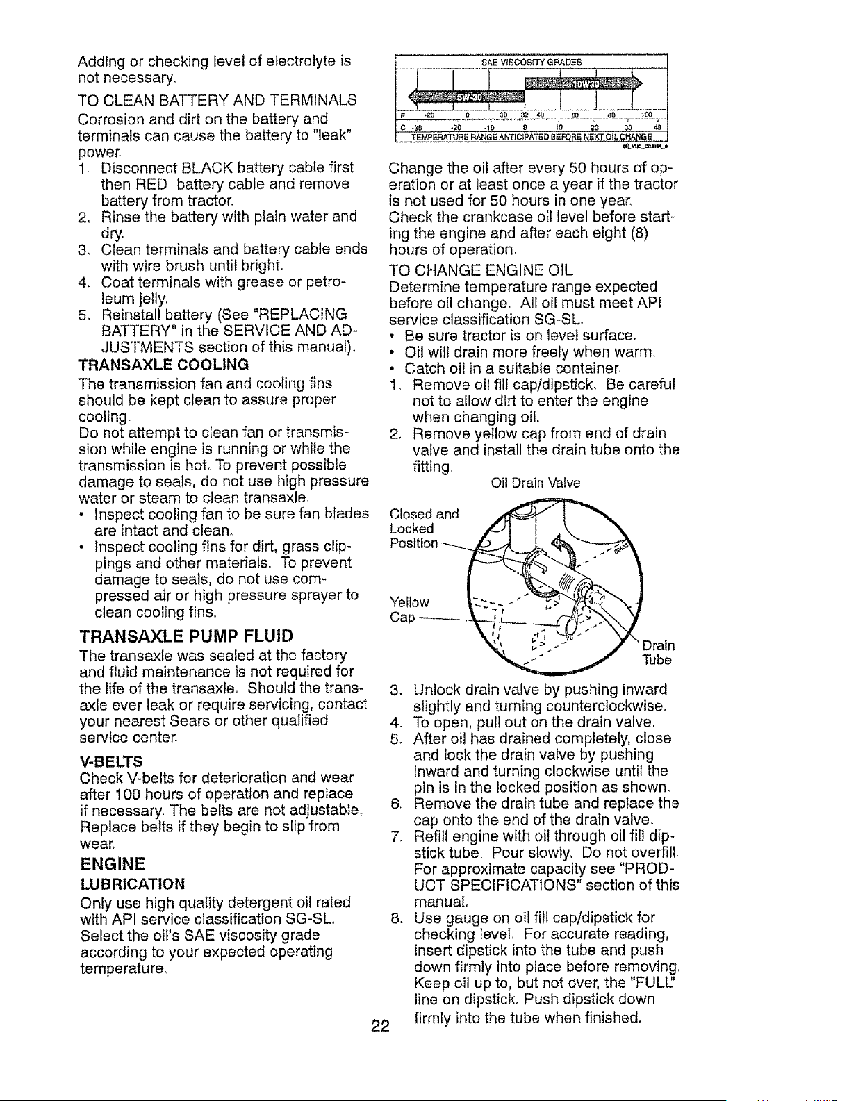
1. Remove oil fill cap/dipstick. Be careful
not to allow dirt to enter the engine
when changing oil.
2. Remove yellow cap from end of drain
valve and install the drain tube onto the
fitting
Oil Drain Valve
Closed and
Locked
Yellow
Cap
22
Tube
3. Unlock drain valve by pushing inward
slightly and turning counterclockwise.
4. To open, pull out on the drain valve,
5. After oil has drained completely, close
and lock the drain valve by pushing
inward and turning clockwise until the
pin is in the locked position as shown.
6. Remove the drain tube and replace the
cap onto the end of the drain valve,
7_ Refill engine with oil through oil fill dip-
stick tube. Pour slowly. Do not overfill.
For approximate capacity see "PROD-
UCT SPECIFICATIONS" section of this
manual.
8. Use gauge on oil fill cap/dipstick for
checking level, For accurate reading,
insert dipstick into the tube and push
down firmly into place before removing,
Keep oil up to, but not over, the "FULl"
line on dipstick. Push dipstick down
firmly into the tube when finished,
AIR FILTER
Your engine will not run properly using
a dirty air filter. Service paper cartridge
every two months or every 25 hours of
operation, whichever occurs first.
Service paper cartridge more often under
dusty conditions.
Replace the paper cartridge annually, or
after every 100 hours of operation.
TO SERVICE CARTRIDGE
• Replace a dirty, bent, or damaged car-
tridge. Handle new cartridge carefully;
do not use if the rubber seal is dam-
aged,
NOTE: Do not wash the paper cartridge
or use pressurized air, as this will damage
the cartridge,
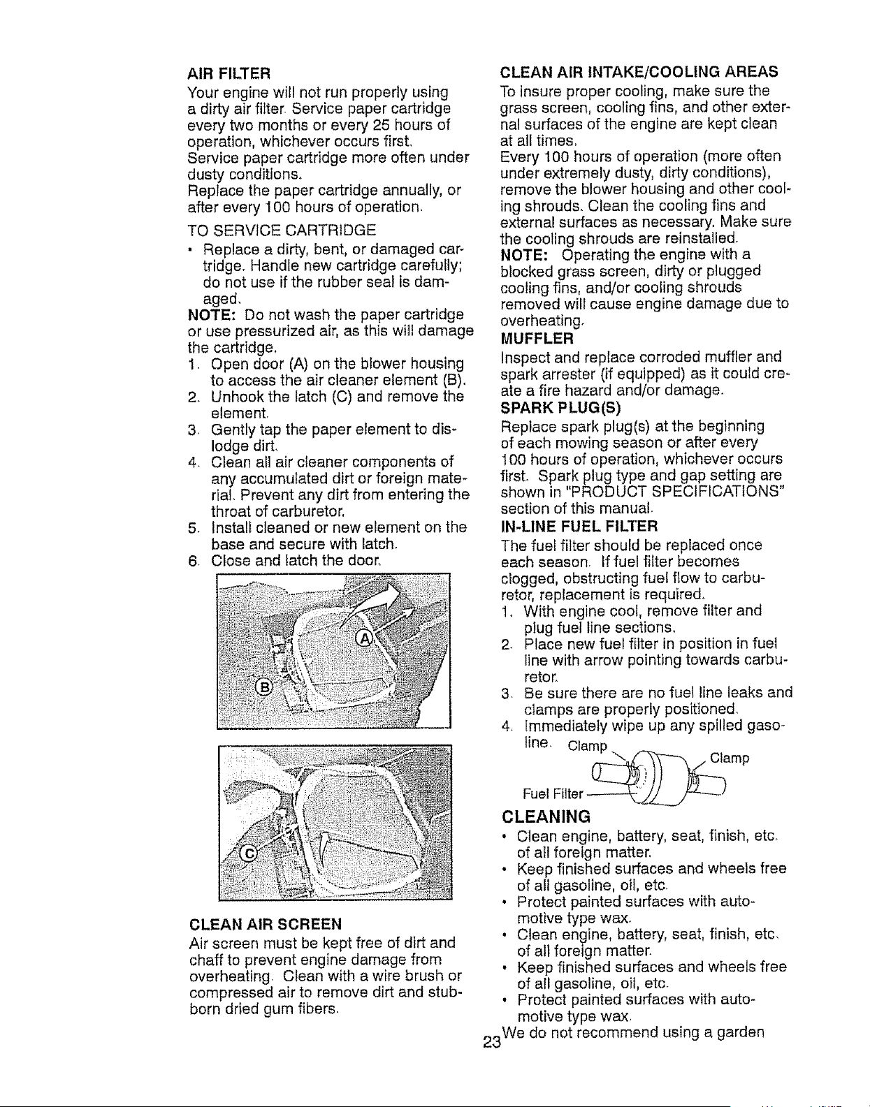
1. Open door (A) on the blower housing
to access the air cleaner element (B),
2. Unhook the latch (C) and remove the
element.
3. Gently tap the paper element to dis-
lodge dirt.
4. Clean all air cleaner components of
any accumulated dirt or foreign mate-
rial. Prevent any dirt from entering the
throat of carburetor,
5. Install cleaned or new element on the
base and secure with latch.
6. Close and latch the door.
CLEAN AIR SCREEN
Air screen must be kept free of dirt and
chaff to prevent engine damage from
overheating. Clean with a wire brush or
compressed air to remove dirt and stub-
born dried gum fibers.
CLEAN AIR INTAKE/COOLING AREAS
To insure proper cooling, make sure the
grass screen, cooling fins, and other exter-
nal surfaces of the engine are kept clean
at all times,
Every 100 hours of operation (more often
under extremely dusty, dirty conditions),
remove the blower housing and other cool-
ing shrouds. Clean the cooling fins and
external surfaces as necessary. Make sure
the cooling shrouds are reinstalled.
NOTE: Operating the engine with a
blocked grass screen, dirty or plugged
cooling fins, and/or cooling shrouds
removed will cause engine damage due to
overheating°
MUFFLER
Inspect and replace corroded muffler and
spark arrester (if equipped) as it could cre-
ate a fire hazard and/or damage.
SPARK PLUG(S)
Replace spark plug(s) at the beginning
of each mowing season or after every
100 hours of operation, whichever occurs
first. Spark plug type and gap setting are
shown in "PRODUCT SPECIFICATIONS"
section of this manual.
IN-LINE FUEL FILTER
The fuel filter should be replaced once
each season. If fuel filter becomes
clogged, obstructing fuel flow to carbu-
retor, replacement is required.
1, With engine cool, remove filter and
piug fuel line sections,
2. Place new fuel filter in position in fuel
line with arrow pointing towards carbu-
retor.
3. Be sure there are no fuel line leaks and
clamps are properly positioned.
4. immediately wipe up any spilled gaso-
line Clamp
Fuel Filter ------___/_J
CLEANING
• Clean engine, battery, seat, finish, etc.
of all foreign matter,
• Keep finished surfaces and wheels free
of all gasoline, oil, etc.
• Protect painted surfaces with auto-
motive type wax.
• Clean engine, battery, seat, finish, etc,
of all foreign matter.
• Keep finished surfaces and wheels free
of all gasoline, oil, etc.
• Protect painted surfaces with auto-
motive type wax.
23We do not recommend using a garden
_ ARNING: TO AVOID SERIOUS INJURY, BEFORE PERFORMING ANY SER-
VICE OR ADJUSTMENTS:
1, Depress brake pedal fully and set parking brake,
2_ Place attachment clutch in "DISENGAGED" position,
3, Turn ignition key to "STOP" and remove key°
4, Make sure the blades and all moving parts have completely stopped,
5, Disconnect spark plug wire from spark plug and place wire where it cannot
come in contact with plug.
TRACTOR
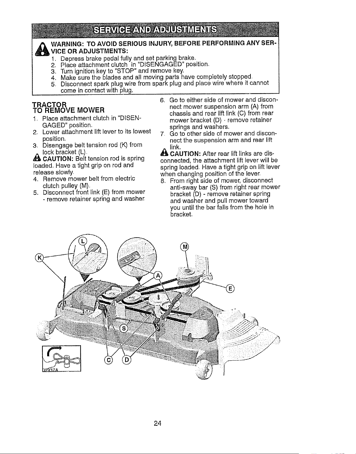
TO REMOVE MOWER
1, Place attachment clutch in "DISEN-
GAGED" position,
2. Lower attachment lift lever to its lowest
position,
3, Disengage belt tension rod (K) from
_lock bracket (L),
CAUTION: Belt tension rod is spring
ioaded. Have a tight grip on rod and
release slowly,
4. Remove mower belt from electric
clutch pulley (M).
5. Disconnect front iink (E) from mower
- remove retainer spring and washer
6_ Go to either side of mower and discon-
nect mower suspension arm (A) from
chassis and rear lift link (C) from rear
mower bracket (D) - remove retainer
springs and washers,
7. Go to other side of mower and discon-
nect the suspension arm and rear lift
link.
CAUTION: After rear lift links are dis-
connected, the attachment lift lever will be
spring Ioaded. Have a tight grip on lift lever
when changing position of the lever,
8, From right side of mower, disconnect
anti-sway bar (S) from right rear mower
bracket (D) - remove retainer spring
and washer and pull mower toward
you until the bar falls from the hole in
bracket,
24
9. Turn tractor steering wheel to the left
as far as it will go 2
10. Slide mower out from under right side 3,
of tractor.
TO INSTALL MOWER
Follow procedure described in "INSTALL
MOWER AND DRIVE BELT" in the As-
sembly section of this manual.
TO LEVEL MOWER
Make sure tires are properly inflated to
the PSI shown on tires, If tires are over
or under inflated, it may affect the appear-
ance of your lawn and lead you to think
the mower is not adjusted properly.
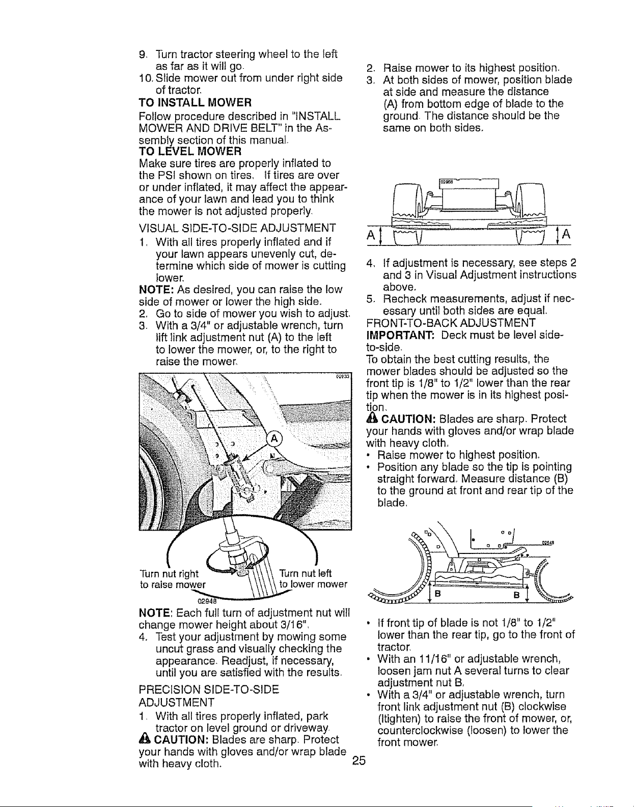
VISUAL SIDE-TO-SIDE ADJUSTMENT
A
1_ With all tires properly inflated and if
your lawn appears unevenly cut, de-
termine which side of mower is cutting
lower,
NOTE: As desired, you can raise the low
side of mower or lower the high side.
2. Go to side of mower you wish to adjust.
3. With a 3/4" or adjustable wrench, turn
lift link adjustment nut (A) to the teft
to lower the mower, or, to the right to
raise the mower.
Turn nut right
to raise mower
Turn nut left
to lower mower
NOTE: Each full turn of adjustment nut will
change mower height about 3/16'L
4. Test your adjustment by mowing some
uncut grass and visuaity checking the
appearance. Readjust, if necessary,
until you are satisfied with the results.
PRECISION SIDE-TO-SIDE
ADJUSTMENT
1. With all tires properly inflated, park
tractor on level ground or driveway.
CAUTION: Blades are sharp. Protect
your hands with gloves and/or wrap blade
with heavy cloth.
Raise mower to its highest position.
At both sides of mower, position blade
at side and measure the distance
(A) from bottom edge of blade to the
ground The distance should be the
same on both sides.
A
4, If adjustment is necessary, see steps 2
and 3 in Visual Adjustment instructions
above.
5. Recheck measurements, adjust if nec-
essary until both sides are equal.
FRO NT-TO- BAC K ADJU STM ENT
IMPORTANT: Deck must be level side-
to-side.
To obtain the best cutting results, the
mower blades should be adjusted so the
front tip is t/8" to I/2" lower than the rear
tip when the mower is in its highest posi-
tion.
CAUTION: Blades are sharp. Protect
your hands with gloves and/or wrap blade
with heavy cloth,
• Raise mower to highest position.
• Position any blade so the tip is pointing
straight forward. Measure distance (B)
to the ground at front and rear tip of the
blade,
• If front tip of blade is not 1/8" to 1/2"
lower than the rear tip, go to the front of
tractor.
• With an 11/16" or adjustable wrench,
loosen jam nut A several turns to clear
adjustment nut B,
• With a 3/4" or adjustable wrench, turn
front link adjustment nut (B) clockwise
(Itighten) to raise the front of mower, or,
counterclockwise (loosen) to lower the
front mower.
25
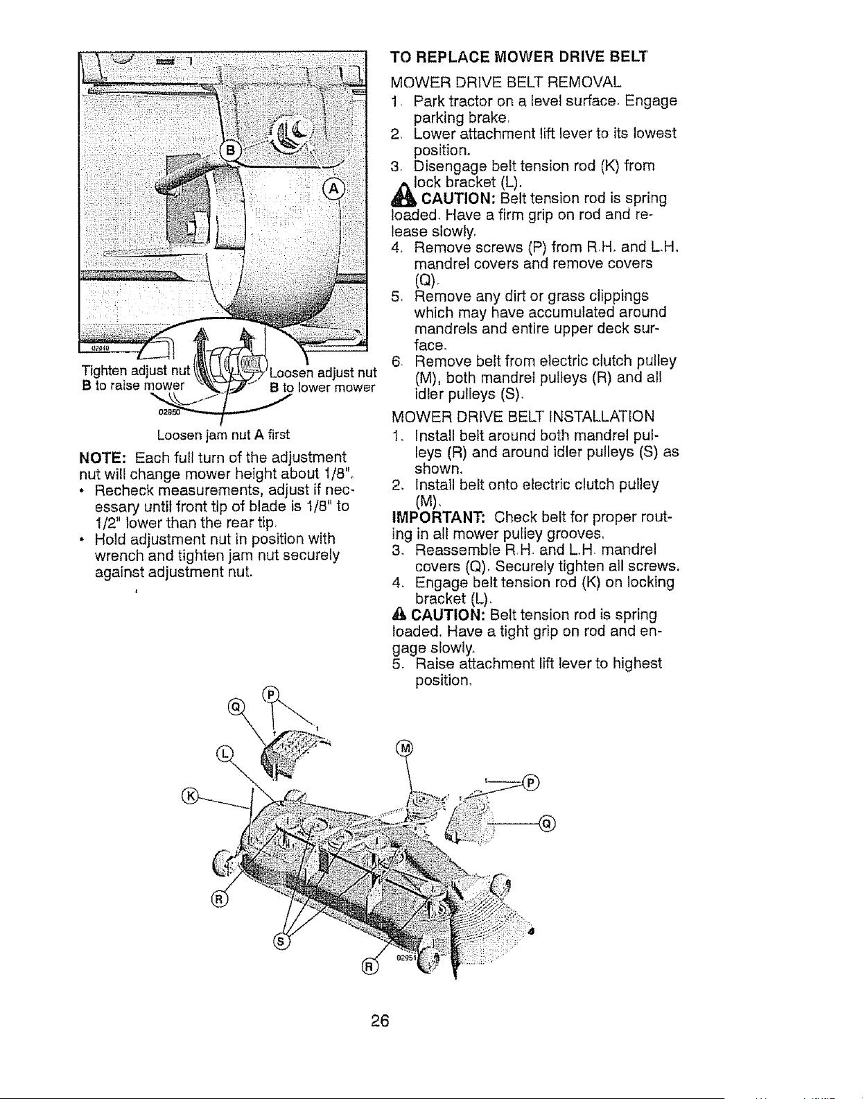
Tighten adjust nut
B to raise mower
Loosen adjust nut
B to lower mower
Loosen jam nut A first
NOTE: Each full turn of the adjustment
nut will change mower height about 1/8".
. Recheck measurements, adjust if nec-
essary until front tip of blade is 1/8" to
1/2" lower than the rear tip,
• Hold adjustment nut in position with
wrench and tighten jam nut securely
against adjustment nut.
\
TO REPLACE MOWER DRIVE BELT
MOWER DRIVE BELT REMOVAL
1, Park tractor on a level surface, Engage
parking brake,
2, Lower attachment lift lever to its lowest
position°
3, Disengage belt tension rod (K) from
_l_OCk bracket (L).
CAUTION: Belt tension rod is spring
loaded, Have a firm grip on red and re*
lease slowly,
4, Remove screws (P) from R H, and L.H.
mandrel covers and remove covers
(Q),
5, Remove any dirt or grass clippings
which may have accumulated around
mandrels and entire upper deck sur-
face_
6. Remove belt from electric clutch pulley
(M), both mandrel pulleys (R) and all
idler pulleys (S),
MOWER DRIVE BELT INSTALLATION
I. Install belt around both mandrel pul-
leys (R) and around idler pulleys (S) as
shown,
2, Install belt onto electric clutch pulley
(M),
IMPORTANT: Check belt for proper rout-
ing in all mower pulley groove&
3, Reassemble RH and L.H mandrel
covers (Q)_ Securely tighten all screws.
4, Engage belt tension rod (K) on locking
bracket (L),
_, CAUTION: Belt tension rod is spring
loaded, Have a tight grip on rod and en-
gage slowly.
5, Raise attachment lift lever to highest
position,
@
26
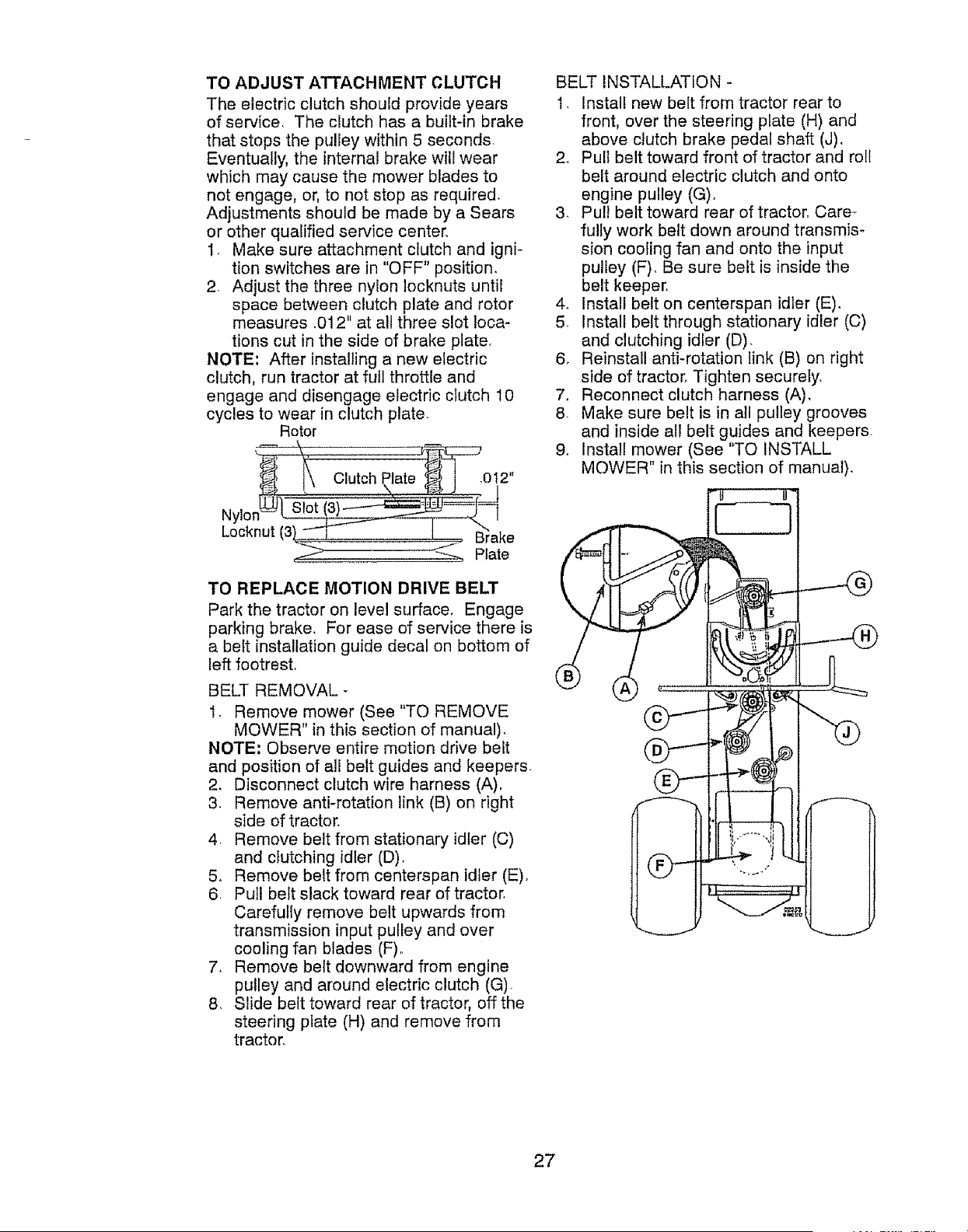
TO ADJUST ATTACHMENT CLUTCH
The electric clutch should provide years
of service. The clutch has a builtqn brake
that stops the pulley within 5 seconds.
Eventually, the internal brake will wear
which may cause the mower blades to
not engage, or, to not stop as required
Adjustments should be made by a Sears
or other qualified service center.
1. Make sure attachment clutch and igni-
tion switches are in "OFF" position.
2. Adjust the three nylon Iocknuts until
space between clutch plate and rotor
measures .012" at all three slot loca-
tions cut in the side of brake plate.
NOTE: After installing a new electric
clutch, run tractor at full throttle and
engage and disengage electric clutch 10
cycles to wear in clutch plate.
Rotor
N,
Locknut
TO REPLACE MOTION DRIVE BELT
Park the tractor on level surface, Engage
parking brake. For ease of service there is
a belt installation guide decal on bottom of
left footrest.
BELT REMOVAL -
1. Remove mower (See "TO REMOVE
MOWER" in this section of manual).
NOTE: Observe entire motion drive belt
and position of all belt guides and keepers.
2. Disconnect clutch wire harness (A),
3. Remove anti-rotation link (B) on right
side of tractor.
4. Remove belt from stationary idler (C)
and clutching idler (D).
5o Remove belt from centerspan idler (E)o
6. Pu]l belt slack toward rear of tractor.
Carefully remove belt upwards from
transmission input pulley and over
cooling fan blades (F).
7. Remove belt downward from engine
pulley and around electric clutch (G).
8. Slide belt toward rear of tractor, off the
steering plate (H) and remove from
tractor.
BELT INSTALLATION -
1. Install new belt from tractor rear to
front, over the steering plate (H) and
above clutch brake pedal shaft (J),
2. Pull belt toward front of tractor and roll
belt around electric clutch and onto
engine pulley (G)o
3. Pull belt toward rear of tractor, Care-
fully work belt down around transmis-
sion cooling fan and onto the input
pulley (F). Be sure belt is inside the
belt keeper.
4. Install belt on centerspan idler (E).
5. Install belt through stationary idler (C)
and clutching idler (D).
6. Reinstall anti-rotation link (B) on right
side of tractor, Tighten securely.
7. Reconnect clutch harness (A).
8_ Make sure belt is in all pulley grooves
and inside all belt guides and keepers.
9. Install mower (See "TO INSTALL
MOWER" in this section of manual).
27
TO CHECK BRAKE
If tractor requires more than five (5) feet to
stop at highest speed in highest gear on a
level, dry concrete or paved surface, then
brake must be serviced.
You may also check brake by:
1. Park tractor on a level, dry concrete or
paved surface, depress clutch/brake
pedal all the way down and engage
parking brake,
2, Disengage transmission by placing
freewheel control in "transmission dis-
engaged" position. Pull freewheel con-
trol out and into the slot and release so
it is held in the disengaged position,
The rear wheels must lock and skid
when you try to manually push the tractor
forward, If the rear wheels rotate, then the
brake needs to be serviced. Contact a
Sears or other qualified service center.
FRONT WHEEL TOE-IN/CAMBER
Your new tractor front wheel toe-in and
camber is set at the factory and is normal,
The front wheel toe-in and camber are
not adjustable. If damage has occurred to
affect the factory set front wheel toe-in or
camber, contact a Sears or other qualified
service center.
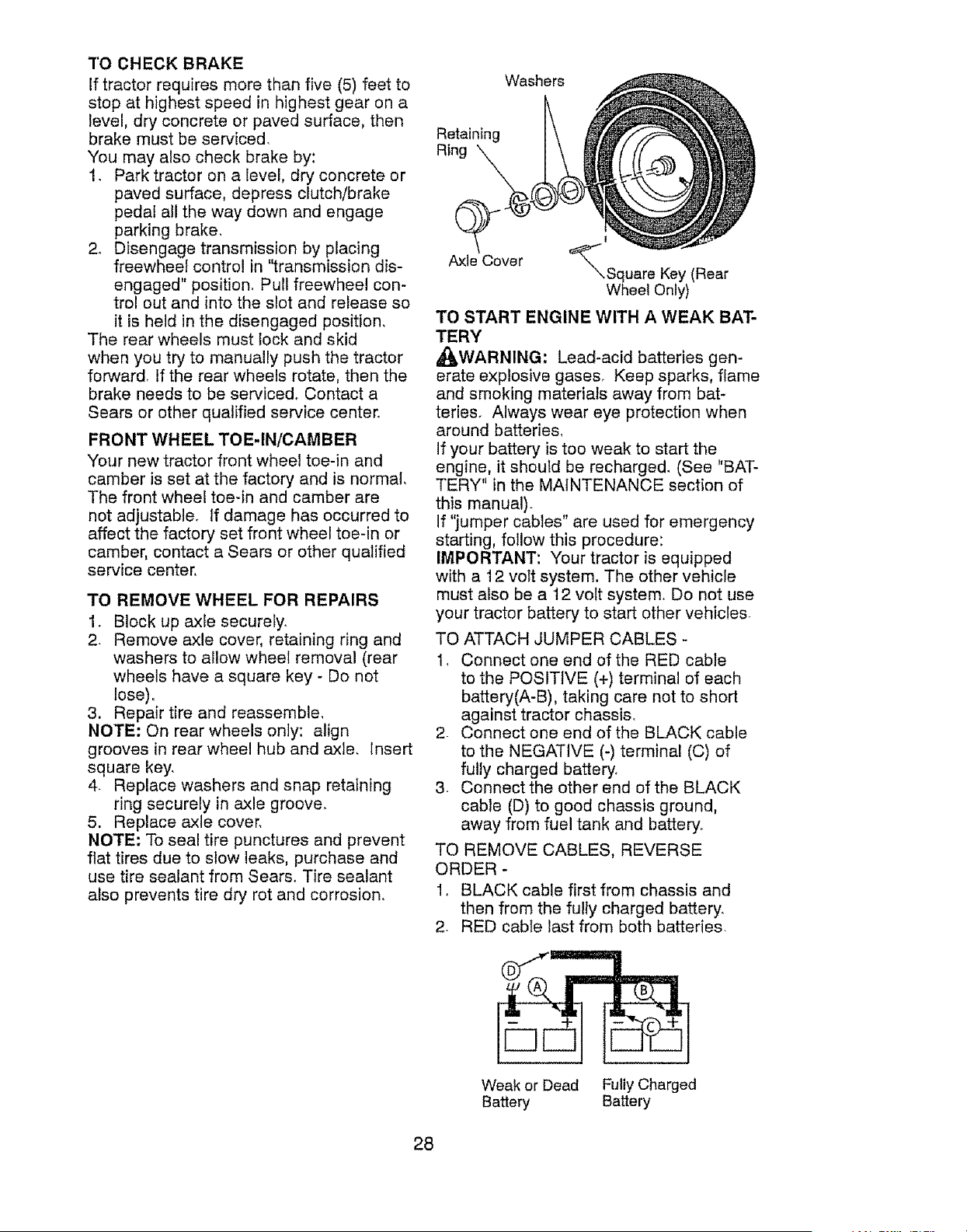
TO REMOVE WHEEL FOR REPAIRS
1. Block up axle securely.
2 Remove axle cover, retaining ring and
washers to allow wheel removal (rear
wheels have a square key - Do not
lose),
3. Repair tire and reassemble_
NOTE: On rear wheels only: align
grooves in rear wheel hub and axle, Insert
square key,
4. Replace washers and snap retaining
ring securely in axle groove,
5. Replace axle cover,
NOTE: To seal tire punctures and prevent
flat tires due to stow leaks, purchase and
use tire sealant from Sears. Tire sealant
also prevents tire dry rot and corrosion.
Washers
Retaining
Ring
Axle Cover
t
'_Square Key (Rear
Wheel Only)
TO START ENGINE WITH A WEAK BAT-
TERY
A0_,WARNING: Lead-acid batteries gen-
erate explosive gases, Keep sparks, flame
and smoking materials away from bat-
teries. Always wear eye protection when
around batterie&
If your battery is too weak to start the
engine, it should be recharged. (See "BAT-
TERY" in the MAINTENANCE section of
this manual).
If "jumper cables" are used for emergency
starting, follow this procedure:
IMPORTANT: Your tractor is equipped
with a 12 volt system. The other vehicle
must also be a 12 volt system. Do not use
your tractor battery to start other vehicles
TO ATTACH JUMPER CABLES -
1_ Connect one end of the RED cable
to the POSITIVE (+) terminal of each
battery(A-B), taking care not to short
against tractor chassis.
2 Connect one end of the BLACK cable
to the NEGATIVE (-) terminal (C) of
fully charged battery.
3. Connect the other end of the BLACK
cable (D) to good chassis ground,
away from fuel tank and battery.
TO REMOVE CABLES, REVERSE
ORDER -
1. BLACK cable first from chassis and
then from the fulty charged battery.
2. RED cable last from both batteries.
Weak or Dead Fully Charged
Battery Battery
28
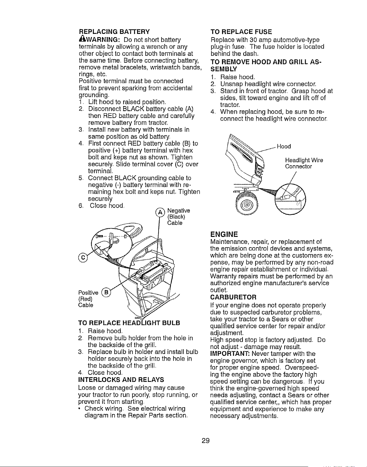
REPLACING BATTERY
I_.WARNING: Do not short battery
terminals by allowing a wrench or any
other object to contact both terminals at
the same time. Before connecting battery,
remove metal bracelets, wristwatch bands,
rings, etc,
Positive terminal must be connected
first to prevent sparking from accidental
grounding,
1. Lift hood to raised position,
2. Disconnect BLACK battery cable (A)
then RED battery cable and carefully
remove battery from tractor,
3 Install new battery with terminals in
same position as old battery_
4. First connect RED battery cable (B) to
positive (+) battery terminal with hex
bolt and keps nut as shown_ Tighten
securely. Slide terminal cover (C) over
terminal°
5. Connect BLACK grounding cable to
negative (-) battery terminal with re-
maining hex bolt and keps nut. Tighten
securely
6, Close hood,
Positive
(Red)
Cable
_ Negative
(Black)
Cable
TO REPLACE ,IGHT BULB
I. Raise hood,
2. Remove bulb holder from the hole in
the backside of the grill
3. Replace bulb in holder and install bulb
holder securely back into the hole in
the backside of the grill.
4 Close hood.
INTERLOCKS AND RELAYS
Loose or damaged wiring may cause
your tractor to run poorly, stop running, or
prevent it from starting
• Check wiring. See electrical wiring
diagram in the Repair Parts section_
TO REPLACE FUSE
Replace with 30 amp automotive-type
plug-in fuse. The fuse holder is located
behind the dash,
TO REMOVE HOOD AND GRILL AS-
SEMBLY
1. Raise hood.
2. Unsnap headlight wire connector,
& Stand in front of tractor. Grasp hood at
sides, tilt toward engine and lift off of
tractor,
4. When replacing hood, be sure to re-
connect the headlight wire connector.
Headlight Wire
Connector
ENGINE
Maintenance, repair, or replacement of
the emission control devices and systems,
which are being done at the customers ex-
pense, may be performed by any non-road
engine repair establishment or individual.
Warranty repairs must be performed by an
authorized engine manufacturer's service
outlet.
CARBURETOR
if your engine does not operate property
due to suspected carburetor problems,
take your tractor to a Sears or other
qua]ified service center for repair and/or
adjustmenL
High speed stop is factory adjusted. Do
not adjust - damage may result.
IMPORTANT: Never tamper with the
engine governor, which is factory set
for proper engine speed, Overspeed-
ing the engine above the factory high
speed setting can be dangerous. ]f you
think the engine-governed high speed
needs adjusting, contact a Sears or other
qualified service center,, which has proper
equipment and experience to make any
necessary adjustments.
29
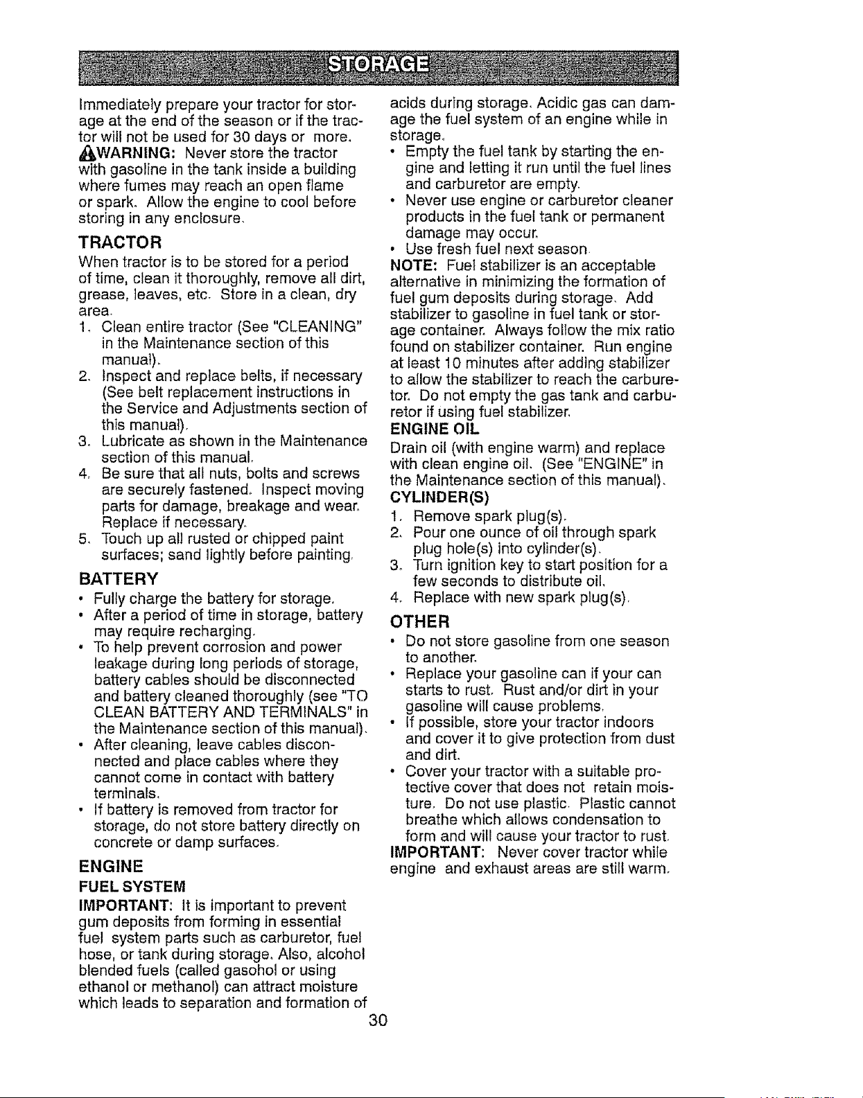
Immediately prepare your tractor for stor-
age at the end of the season or if the trac-
tor will not be used for 30 days or more
_WARNING: Never store the tractor
with gasoline in the tank inside a building
where fumes may reach an open flame
or spark° Allow the engine to cool before
storing in any enclosure
TRACTOR
When tractor is to be stored for a period
of time, clean it thoroughly, remove all dirt,
grease, leaves, etc Store in a clean, dry
area
1 Clean entire tractor (See "CLEANING"
in the Maintenance section of this
manual)
2 Inspect and replace belts, if necessary
(See belt replacement instructions in
the Service and Adjustments section of
this manual)
3o Lubricate as shown in the Maintenance
section of this manual
4 Be sure that all nuts, bolts and screws
are securely fastened° Inspect moving
parts for damage, breakage and wear
Replace if necessary
5 Touch up all rusted or chipped paint
surfaces; sand lightly before painting
BATTERY
• Fully charge the battery for storage
• After a period of time in storage, battery
may require recharging
• To help prevent corrosion and power
leakage during long periods of storage,
battery cables should be disconnected
and battery cleaned thoroughly (see "TO
CLEAN BATTERY AND TERMINALS" in
the Maintenance section of this manual)
• After cleaning, leave cables discon-
nected and place cables where they
cannot come in contact with battery
terminals
• If battery is removed from tractor for
storage, do not store battery directly on
concrete or damp surfaces.
ENGINE
FUEL SYSTEM
IMPORTANT: It is important to prevent
gum deposits from forming in essential
fuel system parts such as carburetor, fuel
hose, or tank during storage Also, alcohol
blended fuels (called gasohol or using
ethanol or methanol) can attract moisture
which leads to separation and formation of
3O
acids during storage Acidic gas can dam-
age the fue! system of an engine while in
storage
• Empty the fuel tank by starting the en-
gine and letting it run until the fuel lines
and carburetor are empty
• Never use engine or carburetor cleaner
products in the fuel tank or permanent
damage may occur
• Use fresh fuel next season
NOTE: Fuel stabilizer is an acceptable
alternative in minimizing the formation of
fuel gum deposits during storage Add
stabilizer to gasoline in fuel tank or stor-
age container Always follow the mix ratio
found on stabilizer container Run engine
at least 10 minutes after adding stabilizer
to allow the stabilizer to reach the carbure-
tor Do not empty the gas tank and carbu-
retor if using fuel stabilizer
ENGINE OIL
Drain oil (with engine warm) and replace
with clean engine oil (See "ENGINE" in
the Maintenance section of this manual)
CYLINDER(S)
1 Remove spark plug(s)
2 Pour one ounce of oil through spark
plug hole(s) into cylinder(s)
3o Turn ignition key to start position for a
few seconds to distribute oil.
4 Replace with new spark plug(s)
OTHER
• Do not store gasoline from one season
to another.
• Replace your gasoline can if your can
starts to rust Rust and/or dirt in your
gasoline will cause problems
• If possible, store your tractor indoors
and cover it to give protection from dust
and dirt
• Cover your tractor with a suitable pro*
tective cover that does not retain mois-
ture Do not use plastic Plastic cannot
breathe which allows condensation to
form and will cause your tractor to rust
IMPORTANT: Never cover tractor while
engine and exhaust areas are still warm

TROUBLESHOOTING CHART:
See appropriate section in manual unless directed to Sears service center
PROBLEM CAUSE CORRECTION
Will not start
Hard to start
1. Out of fuel.
2. Engine not"CHOKED"
properly.
3. Engine flooded.
4o Bad spark plug.
5. Weak or dead battery.
& Dirty air fiIter.
7. Dirty fuet fiiter_
8. Water in fuel.
1. Fill fuel tank.
2 See "TO START ENGINE" in
Operation section.
3. Wait severat minutes before
attempting to start.
4. Replace spark plugo
5. Recharge or replace battery.
6. Cban/rep}ace air filter.
. Replace fuel filter.
. Empty fuel tank and carbure-
tor, refill tank with fresh gas-
oline and replace fuel filter.
9. Check all wiring.
1O. See "To Adjust Carburetor"
in Service and Adjustments
section.
1. Contact a Sears or other
qualified service center.
9. Loose or damaged wiring.
10. Carburetor out of adjustment.
Engine will not
turn over
JEngine clicks but
will not start
Loss of power
1. Engine valves out of
adjustmenL
1. Dirty air filter
2. Bad spark plug.
3. Weak or dead battery.
. Dirbj fueI filter.
• Sta}e or dirty fuef.
6. Loose or damaged wiring.
7. Carburetor out of adjustment.
8, Engine valves out of
adjustment,
, Brake pedal not depressed.
• Attachment clutch is engaged
3. Weak or dead battery,
4. Blown fuse,
5. Corroded battery terminal&
6. Loose or damaged wiring.
7, Faulty ignition switch.
8. Faulty solenoid or starter
,
Faulty operator presence
switch(as),
I2" Weak or dead battery,
• Corroded battery terminals.
3 Loose or damaged wiring.
4. Faulty solenoid or starter,
1. Cutting too much grass/too
fast,
2, Throttle in "CHOKE" position.
3. Buitd-up of grass, leaves and
trash under mower,
4, Dirty air filter,
5, Low oil level/dirty oil.
1. Clean/replace air filter•
2. Replace spark plug.
Replace fuel filter,
,I. Recharge or replace battery.
• Empty fuel tank and refill tank
with fresh, clean gasoline,
5. Check all wiring,
7, See "To Adjust Carburetor" in
Service and Adjustments
section.
8. Contact a Sears or other
qualified service center.
2' Depress brake pedal•
. Disengage attachment clutch.
3. Recharge or replace battery.
, Replace fuse.
, Clean battery terminal&
& Check all w_nng
7. Check/replace ignition switch
8. Check/replace solenoid or
starter.
9. Contact a Sears or other
qualified service center.
1. Recharge or replace battery.
2. Clean battery terminals.
3. Check al! wiring°
4. Check/replace solenoid or
starter,
1_ Raise cutting height/reduce
speed
. Adiust throttle control.
. Clean underside of mower
housing.
4. Clean/replace air filter.
5. Check oil level/change oil.
31
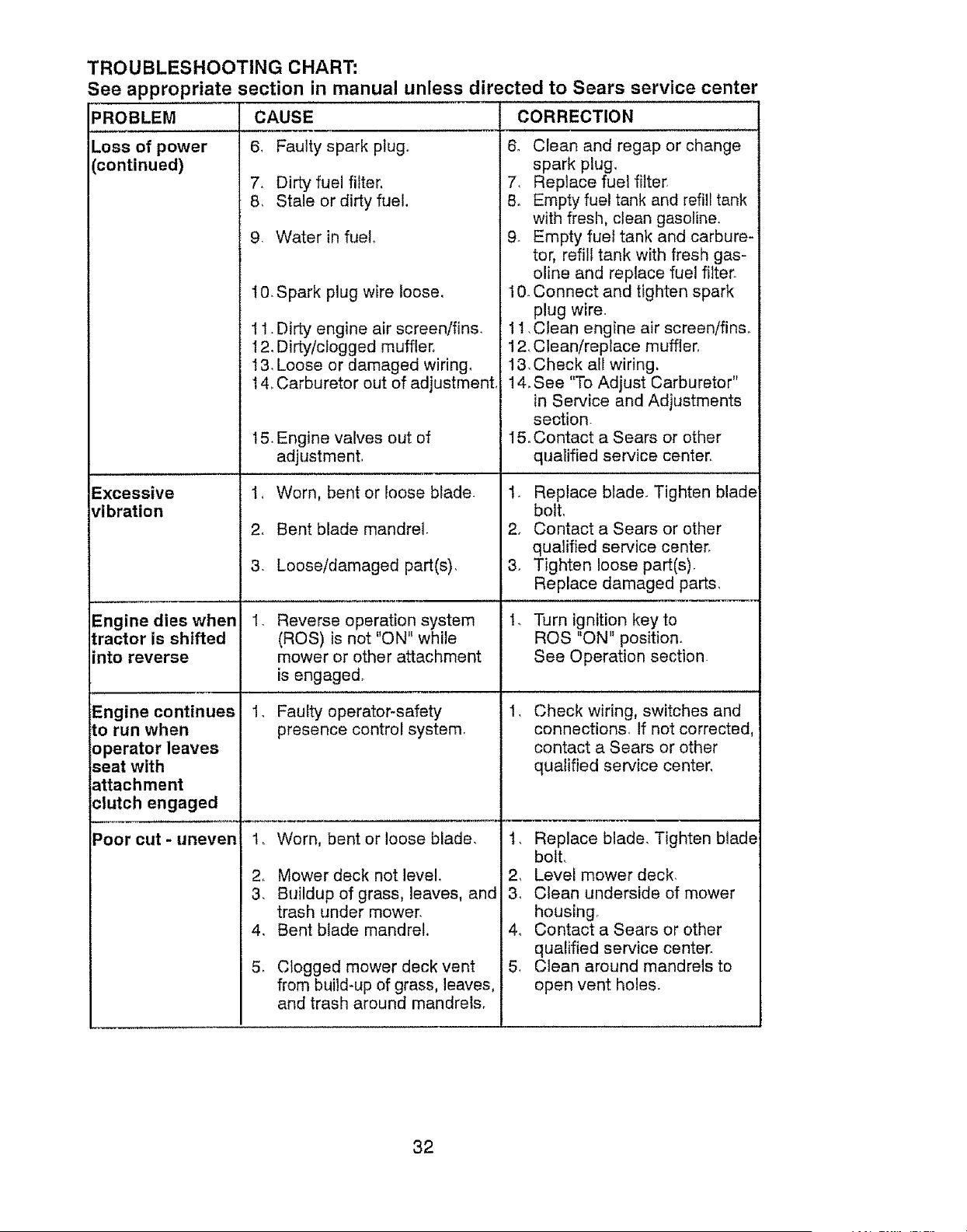
TROUBLESHOOTING CHART:
See appropriate section in manual unless directed to Sears service center
PROBLEM CORRECTION
Loss of power
continued)
Excessive
ribration
Engine dies when
!ractor is shifted
into reverse
Engine continues
to run when
operator leaves
seat with
attachment
clutch engaged
Poor cut - uneven
CAUSE
6, Faulty spark plug.
7. Dirty fuel filter,
8, Stale or dirty fuel,
9. Water in fuel,
10. Spark plug wire loose,
11. Dirty engine air screen/fins,
12, Dirty/clogged muffler.
I3, Loose or damaged wiring,
t 4, Carburetor out of adjustment,
15. Engine valves out of
adjustment.
1, Worn, bent or loose blade.
2. Bent blade mandrel.
3. Loose/damaged part(s),
.
Reverse operation system
(ROS) is not "ON" while
mower or other attachment
is engaged.
1, Faulty operator-safety
presence control system.
t,
2,
3,
4,
5.
Worn, bent or loose blade.
Mower deck not level
Buildup of grass, leaves, and
trash under mower,
Bent blade mandrel,
Clogged mower deck vent
from build-up of grass, leaves,
and trash around mandrels,
6. Clean and regap or change
spark plug,
7, Replace fuel filter.
8. Empty fuel tank and refill tank
with fresh, clean gasoline.
9. Empty fuel tank and carbure-
tor, refill tank with fresh gas-
oline and replace fue! filter.
10_Connect and tighten spark
plug wire.
11, Clean engine air screen/fin&
12, Clean/replace muffler.
13, Check all wiring.
14, See "To Adjust Carburetor"
in Service and Adjustments
section.
I5, Contact a Sears or other
qualified service center,
1. Replace blade, Tighten blade
boll
2, Contact a Sears or other
qualified service center,
3, Tighten loose part(s).
Replace damaged parts,
1. Turn ignition key to
ROS "ON" position.
See Operation section.
,
Check wiring, switches and
connections, If not corrected,
contact a Sears or other
qualified service center,
1, Replace blade, Tighten blade
bolt,
2, Level mower deck,
3, Clean underside of mower
housing,
4, Contact a Sears or other
qualified service center,
5, Clean around mandrels to
open vent holes.
32
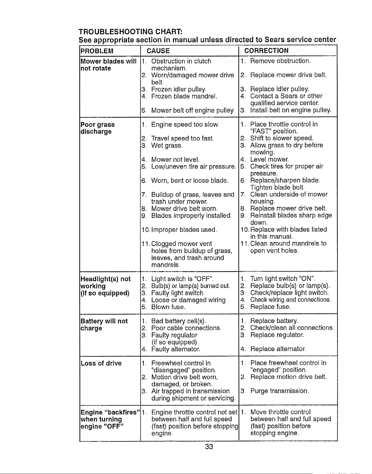
TROUBLESHOOTING CHART:
See appropriate section in manual unless directed to Sears service center
PROBLEM
Mower blades will
not rotate
Poor grass
discharge
Headlight(s) not
working
(if so equipped)
Battery will not
charge
Loss of drive
Engine "backfires"
_vhen turning
engine "OFF"
CAUSE
1. Obstruction in clutch
mechanism.
2. Worn/damaged mower drive
belt,
3. Frozen idler pulley.
4. Frozen blade mandrel.
5. Mower bek off engine puliey.
1. Engine speed too slow.
2o Travel speed too fast.
3, Wet grass,
4. Mower not level.
5. Low!uneven tire air pressure_
8. Worn, bent or loose blade.
7, Buildup of grass, leaves and
trash under mower,
8. Mower drive belt worn.
9. Blades improperly installed-
10. Improper blades used.
Clogged mower vent
holes from buildup of grass,
leaves, and trash around
mandrels.
1. Light switch is "OFF".
2, Bulb(s) or lamp(s) burned out.
3. Faulty light switch.
4, Loose or damaged wiring.
5. Blown fuse.
1_ Bad battery ceil(s).
2, Poor cable connections.
3. Faulty regulator
(if so equipped).
4. Faulty alternator.
1. Freewheel control in
"disengaged" position,
2, Motion drive belt worn,
damaged, or broken,
3, Air trapped in transmission
during shipment or servicing,
,
Engine throttle control not set
between half and full speed
(fast) position before stopping
engine
CORRECTION
1, Remove obstruction,
2, Replace mower drive beit,
3. Replace idler pulley,
4. Contact a Sears or other
qualified service center.
3, Install belt on engine pulley_
1. Place throttle control in
"FAST" position.
2. Shift to siower speed,
3_ Allow grass to dry before
mowing.
4. Level mower.
5. Check tires for proper air
pressure.
6. Replace/sharpen blade°
Tighten blade bolt.
7, Clean underside of mower
housing.
8, Replace mower drive belt,
9. Reinstall blades sharp edge
down.
10, Replace with blades listed
in this manual,
11. Clean around mandrels to
open vent holes.
1, Turn light switch "ON".
2. Replace bulb(s) or lamp(s)_
3. Check/replace light switch.
4, Check wiring and connections.
5. Replace fuse,
1. Replace battery.
2. Check/clean all connections,
3, Replace regulator,
4, Replace alternator,
1. Place freewheel control in
"engaged" position.
2. Replace motion drive belto
3. Purge transmission.
Move throttle control
between half and full speed
(fast) position before
stopping engine,
.
33
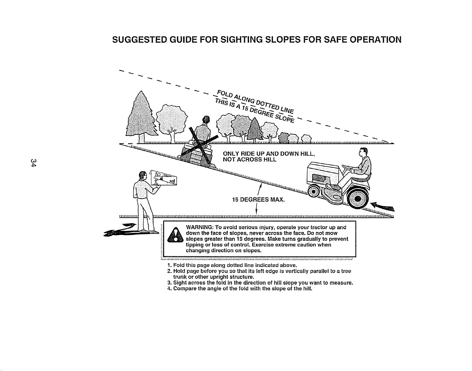
SUGGESTED GUIDE FOR SIGHTING SLOPES FOR SAFE OPERATION
03
4_
ONLY RIDE UP AND DOWN HILL,
NOT ACROSS HILL
15 DEGREES MAX.
_ ARNING: To avoid serious injury, operate your tractor up and
down the face of slopes, never across the face, Do not mow
slopes greater than 15 degrees, Make turns gradually to prevent
tipping or loss of control. Exercise extreme caution when
changing direction on slopes.
1. Fold this page along dotted line indicated above.
2. Hold page before you so that its left edge is vertically parallel to a tree
trunk or other upright structure,
3. Sight across the fold in the direction of hilt slope you want to measure.
4. Compare the angle of the fold with the slope of the hill,
Garantfa ................................................... 35
Reglas de Segufidad ..................................... 36
Especificaciones del Producto ................... 39
Montaje/Pre Operaci6n ................................ 41
Operaci6n ................................................... 45
Mantenimiento ...................................... 53
Programa de Mantenimiento ..................... 53
Servicio y Ajustes ....................................... 57
Atmacenamiento .......................................... 63
Identificaci6n de Probtemas ......................... 64
Servicio Sears ............................... Contratapa
Partes de Repuesto ....... Vea el Manual Ingl6s
Ingles del DueSe
GARANTiA LIMITADA PARA EL TRACTOR Y LA BATER{A CRAFTSMAN
2 ANOS PARA EL TRACTOR
Siempre que su uso y mantenimiento se realicen de acuerdo alas instrucciones del Manual del
Operador, si este tractor tlega a fallar debido a un defecto de matertales o de fabricaci6n dentro
de un plazo de dos (2), aSos a part# de la fecha de compra, llame al 1-800-4-MY-HOME®, o bien
gestione una reparaclon sin cargo.
Durante los primeros 30 dias de dicho plazo, no se le cobrar& nada pot reparar el producto en su
domicilio. Para su conveniencia, podr& seguir contando con la posibilidad de obtener el service de
la garantia a domicilio una vez transcurridos los primeros 30 dias, pero en ese caso deber& pagar
un vi&tico Usted podr& evitarse et costo del vi&tico si Ileva el producto a un centro de servicios
autorizado de Craftsman. Para saber cu&l le queda rn&s cerca, llarne al 1-800-4-MY-HOME®.
La cobertura de la garantia de} tractor no incfuye:
• Aquellos elementos fungibles que se desgasten por el uso normal, incluidos, de rnanera no
taxativa, las cuchillas, bujJas, fittros de aire, correas y filtros de aceite
• Los serviclos de rnantenimiento est&ndar, carnbios de aceite o ajustes de motor..
• Los cambios o reparaciones de neum&ticos pinchados por objetos extraiSes, tales corno ctavos,
espinas, tocenes o trozos de vidrio.
• Las reparaciones que sea precise hacer debido a rnalas t_cnicas de manejo por parte del opera-
dot, entre las que se incluyen, de manera no taxativa, los daSos causados por arrastrar objetos
yendo m&s all& de la capacidad del tractor, el choque con objetos que tuerzan el marco o el eje
del cigL_eSal,o la aceleraci6n excesiva del motor
• Las reparaciones que sea preciso hacer debido a la negligencia del operador, entre las que
se incluyen, de rnanera no taxativa, los daSos el6ctricos y rnec&nicos por guardar la unidad
de rnanera incorrecta, la no utilizaci6n del grado y la calidad apropiados de aceite para motor,
el no mantener el piso libre de restos y escombros que puedan entrar en combustiSn, o el no
mantener el equipo de acuerdo a las instrucciones de! manual del operador.
• Las limpiezas o reparaciones del motor (sistema de combustible) que sea preciso hacer porque
se prueba que el combustible est& contaminado u exidado (pasado). En general, se debe utili-
zar el combustible dentro de los 30 dlas posteriores a su fecha de compra.
• El deterioro y desgaste normales de las terminaciones exteriores, o la sustituci6n de las etiqu-
etas del producto.
• La bater{a, la coat est& cubierta pot s61o g0 d[as, corno se establece a continuaci6n.
90 DiAS PARA LA BATERiA
Por un plazo de noventa (90) dias a partir de la fecha de compra, si la baterla que viene con este
tractor presenta algun defecto de materiales o de fabricaci6n (al probarla, cornnprobarnos que no
mantiene la carga), le ser& reemplazada sin costo.
Durante los primeros 30 dias a partir de la compra, no se le cobrar& por realizar el reernplazo de
ta bateria en su domicilio. Para su conveniencia, podr#, seguir contando con ia posibilidad de
obtener el servicio de la garantia a domicilio, pero en ese caso, deber& pagar un vi&tico. Usted
podr& evitarse el cesto del vi&tico si lleva la bateria a un Centro de Servicios autorizado de
Craftsman. Para saber cu&l le queda m&s cerca, IEameal 1-800-4-MY-HOME®o
La totalidad de la cobertura de la garantia del tractor y la bateria quedar& sin efecto en caso que el
producto sea utilizado con fines cornerciales o de alquiler.
La presente garantfa s61o ser& aplicable si el producto se encuentra dentro de los Estados Unidos
La presente garantFa le otorga derechos legales especificos. Por otra parte, puede que usted
tenga otros derechos, los cuales varian de estado a estado
Sears, Roebuck and Co., Hoffman Estates, IL 60179
35
_PELIGRO: Esta Maquina cortadora es capaz de amputar las manosy los pies y de lanzar
objetos, si no se observan ias lnstrucciones de segurtdad sigutentes se pueden producir
lesiones graves o la muerte.
•_ADVERTENCIA: Siempre desconecte el
alambre de la bujia y p6ngalo donde no pueda
entrar en contacto con fa bujia, para evitar el
arranque per accidente, durante la preparaciSn,
el transporte, el ajuste o cuando se hacen
reparaciones.
_ADVERTENCIA: No avance cuesta abajo a
punto muerto ya que podria perder el control
del tractor.
_ADVERTENCIA: Remotque sotamente los
accesorios recomendados y conformes a las
caracter[sticas indicadas per el fabricante de
su tractor. Tenga cuidado y prudencia al utilizar
el tractor. Cuando se encuentre en un declive,
oper utilizando exclusivamente la velocidad
m_s baja. En case de un declive una carga ex-
cesiva podria resuttar peligrosa, Los neum&ti-
cos pueden perder la tracci6n con el suelo y
hacerle perder el control de su tractor,
_,ADVERTENCIA: El tube de escape del
motor, algunos de sus constituyentes y algunos
componentes del vehiculo contienen o despren-
den productos quimicos conocidos en el Estado
de California come causa de c&ncer y defectos
al nacimiento u otros daf_os reproductivos.
_ADVERTENOIA: Los bornes, terminales y
accesorios relatives de la bater[a contienen
plomo o compuestos de plomo, productos
quimicos conoc_dos en el Estado de California
come causa de c&ncer y defectos at nacimiento
u otros daSos reproductlvos. Lavar las manes
despu_s de manipularlos°
I. FUNOIONAMIENTO GENERAL
• Leer, entender y seguir todas las instruccio-
nes sobre ta m&quina yen el manual antes
de empezar,
• No poner las manes o los pies cerca de
partes giratorias o debajo de la m&quina.
mantener siempre limpia la abertura de
descarga.
• Permitir el funcionamiento de la m&quina
s61o a adultos que tengan familiaridad con
las tnstrucciones.
• Limpiar el &rea de objetos come piedras,
juguetes, cables, etc. que pueden ser recogi-
dos y disparados con las cuchillas.
• Asegurarse de que el &rea est6 libra de otras
personas antes de ponerta en marcha. Parar
lam&quina si alguien antra en el &rea.
• Nunca Ilevar pasajeros,
• No cortar marcha atr&s al no set absolu-
tamente necesario_ Mirar siempre abajo y
delante mientras se precede atr_.s.
• Nunca dirigir el material descargado hacia
nadie, Evitar descargar material contra
paredes u obstrucciones. El material podria
rebotar hacia el operador. Parar las cuchillas
cuando se pasan superficies de gray&
36
• No hacer funcionar la m&quina sin el
captador de hierba entera, ta protecci6n de
descarga u otros dispositivos de seguridad
en su lugar yen buenas condiciones
• Ralentizar antes de girar,
• Nunca dejar una m&quina encendida sin vigF
lancia, Apagar siempre las cuchitfas, poner el
freno de estacionamiento, parar el motor, y
quitar las llaves antes de bajar.
• Desconectar las cuchiilas cuando no se
corta_ Apagar el motor y esperar que todas
las partes est_n completamente paradas
antes de limpiar la m&quina, quitar el capta-
dor de hierba, o desatascar la protecci6n de
descarga.
• Hacer funcionar la m&quina s61ocon la luz
del dfa o luz artificial buena,
• No hacer funcionar la m&quina estando bajo
los efectos de alcohol o droga.
• Poner atenci6n al tr&fico cuando se opera
cerca de calles o se cruzan.
. Poner la m&xima atenci6n al cargar o descar-
gar ta m&quina en una caravana o cami6n,
• Llevar siempre gafas de protecci6n cuando
se hace functonar la maquina.
• Los dates indican que los operadores a
partir de los 60 aSos est&n afectados per
un gran porcentaje de heridas relativas a la
conducci6n del cortac_sped. Estos opera-
dores tenddan que evaluar su habilidad de
hacer funcionar el cortac_sped de mode 1o
bastante seguro para proteger a st mismos y
a otras personas de heridas graves.
• Seguir las recomendaciones del fabricante
para los pesos y contrapesos de las ruedas,
• Mantener Ia m&quina libre de hierba, hojas
u otros escombros que pueden tocar el
tube de escape / partes del motor calientes
y quemarse. No permitir que el puente del
cortac_sped cargue hojas u otros residues
que pueden causar acumulaciones. Ltmpiar
toda salpicadura de aceite o carburante an-
tes de hacer operaciones sobre la m&quina o
guardada, Dejar]a enfriar antes de guardarla.
il, FUNCIONAMIENTO EN PENDIENTES
Las pendientes son et mayor factor de acciden-
tes relatives a la p_rdida de control y vuelco,
qua pueden causar severas heridas o muerte,
El funcionamtento en pendientes requiere una
atenci6n extra, Si no es posible hacer marcha
atr&s en una pendiente o site sientes inco-
mode, no la cortes.
. Cortar hacia arriba y abajo de una pendiente,
no de mode horizontal.
• Porter atenciones a los hoyos, Ias raices, los
bultos, las piedras u otros objetos escon-
didos. El terreno irregular puede volcar la
m&quina, La hierba alta puede esconder
obst&cutos_
. Escogerunavelocidaddemarchabaiade
modoquenoseanecesariopararseo cam-
biarestandoenunapendiente,
• Nocortarlahlerbamojada,Lasruedas
puedenperdertracci6n
PonersIempreunamarchacuandoseest&
enpendtentes,Noponerenpuntomuertoe
trcuestaabajo.
• Evitararrancar,pararseogirarenuna
pendJenteStlasruedaspierdentracciSn,
desconectartascuchillasy procederdespa-
ciocuestaabajoenlapendiente_
• Mantenertadolosmovimientosenlaspen-
dienteslentosy gradual,Nohacercambios
repentinosdevelocidadod]recci6n,yaque
puedencausarelescapedela m&quinao
• Porterla m&ximaatenci6ncuandolamA-
quinafuncionaconcaptadoresdehierba
uotrosdispositivosenganchados;pueden
afectarlaestabilidaddelamAquina,Nousar
enpendientesempinados.
• Nointentarestabilizarlam&quinaponiendo
el pieenetterreno.
• Nocortarcercadebajadas,cunetasy orillaso
LasmAquinapuedevolcarseimprovisamente
sfunaruedaest&eneibordeosehunde,
III. NINES
Si eloperadornoponeatenciSna la presencia
delosniSospuedenocurriraccidentestrAgicos.
Losnir_osa menudoestAnatraidosparla mA-
quinaylasactividaddecortar,Nodarparhecho
de quelosniSossequedenadondeestabanta
(_ltimavez que los vistes.
• Mantener los niSos fuera del Area de carte y
vigilados par un adulto responsable que no
sea el operador.
* Ester alerta y apagar la mAquina si un niSos
entra en el Area.
. Antes y durante la marcha atrAs, mirar ariel-
ante y abajo para ver si hay nirios pequeSos.
. Nunca Ilevar niSos, incfuso si hay las
cuchilfas apagadas, Podrian caer y hedrse
sedamente o interferir con el funcionam}ento
seguro de Ia mAquina, los niSos que se han
llevado precedentemente pueden aparecer
de pronto en e{ Area de carte par otto paseo
y ser atropellados o tumbados par ta mA-
quina
. Nunca dejar que los nifos manipulen Ia
mAquina_
. Tenet el m&ximo cuidado cuando se acerca
a cantos ciegos, arbustos, Arboles u otros
objetos que pueden impedir ta vista de nir_os,
IV. REMOLQUE
. Remolcar sSIo con una m&quina que tenga
un gancho diseSado para remolcar. En-
ganchar el equipo o remolcar s61o en el
punto dispuesto al efecto.
, Seguir ias recomendaciones del productor
con respecto a los limites del equipo par
remolcar y el remolque en pendientes.
• Nunca permitir que n]t_os u etras personas
est_n dentro del equipo par remolcar.
• En pendientes, el peso del equipo remo[cado
puede causar la perdida de tracci6n y la
p#rdida de control.
• Viajar despacio y dejar m&s distancia para
frenar,
V. SERVIClO
MAN|PULACI6N SEGURA DE LA GASOLINA
Para evitar heridas personales o da#,os a las
cosas, poner el maxima cuidado a la hera de
manipular la gasolina_ La gasolina es extrema-
mente inflamabte y los vapores son explosives.
• Apagar todos los cigarriltos, cigarros, pipas y
otras fuentes de ignici6n_
• Usar s6Fo centenedores para gasolina apro-
hades.
• Nunca quitar et tap6n de la gasolina o aSadir
carburante con el motor en marcha, dejar
enfriar el motor antes del abastecimiento de
la gasolina
• Nunca abastecer la mAquina al interior de un
local.
• Nunca guardar la mAquina o el contenedor
del carburante donde haya una llama abierta,
chispas o una luz pilate coma un calentador
de agua u otros dispositivos.
• Nunca Ilenar los contenedores al interior de
un vehiculo o en una caravana o cami6n
recubiertos con un forro de plAstico. Colocar
siempre los contenedores en el terreno lejos
del vehiculo cuando se estA Ilenando.
• Quitar el equipo de gas del cami6n o cara-
vana y abastecedo en el terrenoo Si no es
posiNe, abastecer dicho equipo con un con-
tenedor portAtit, mAs bIen que de un surtidor
de gasolina
• Mantener la boquilla a contacto del borde
del dep6sito de carburante o la abertura det
contenedor durante toda la operaci6n de
abastecimiento. No utilizar un dispositivo con
bequilla cerrada-abierta,
• Si so vierte carburante sabre la ropa, cambi-
arse la ropa inmediatamente,
• Nunca IIenar el depSsito mAs de 1odebido_
Velvet a colocar el tap6n del gas y cerrar de
modo firme.
OPERACIONES DE SERVICIO GENERALES
. Nunca hacer funcionar la mAquina en un
Area cerrada.
• Mantener todas las tuercas y pernos apre-
tados para asegurarse de que trabaja en
condiciones seguras.
• Nunca modificar los dispositivos de seguri_
dad, Controtar su correcto funcionamiento
regularmente.
37
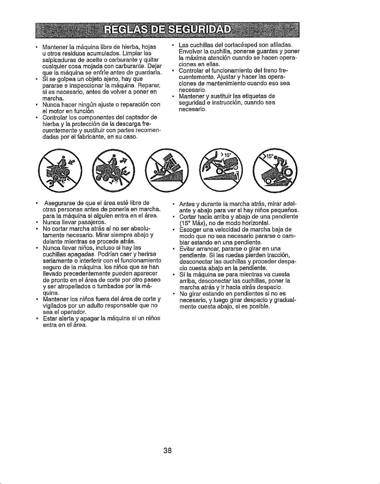
• Mantener la mAquina tibre de hierba, hojas "
u otros residues acumulados. Umpiar tas
salpicaduras de aceite o carburante y quitar
cualquter cosa mojada con carburante, Dejar
que la m&quina se enfrfe antes de guardarla. "
Si se golpea un objeto ajeno, hay que
pararse e inspeccionar la mAquina. Reparar,
si es necesario, antes de volver a poner en
marcha,
Nunca hacer ning_n ajuste o reparaci6n con
el motor en funci6n
Controlar los componentes del captador de
hiarba y la pretecct6n de la descarga fre-
cuentemente y sustituir con partes recomen-
dadas per el fabricante, en su case,
i
Las cuchilEas de! cortac_sped son affiadaso
Envolver la cuchilla, ponerse guantes y poner
la maxima atenci6n cuando se hacen opera-
ciones en ellas.
Controlar el funcionamiento det freno fre-
cuentementeo Ajustar y hacer las opera-
ciones de mantenimiento cuando eso sea
necesario.
Mantener y sustitu]r las etiquetas de
seguridad e instrucci6n, cuando sea
necesario.
• Asegurarse de que el Area est_ libra de
otras personas antes de ponerla en marcha.
para la mAquina si alguien entra en el Area.
• Nunca llevar pasajeros.
. No cortar marcha atr_s al no ser absolu-
tamente necesario. Mirar siempre abajo y
delante mientras se precede atr&so
• Nunca Ilevar nifos, incluso si hay las
euchillas apagadas_ Podr_an caer y herirse
seriamente o interferir con el funcionamiento
seguro de la mAquina, los ni6os que se han
Itevado precedentemente pueden aparecer
de pronto en el Area de corte per otro paseo
y ser atropellados o tumbados per la mR-
quina.
• Mantener los nir3os fuera del Area de corte y
vfgIlados per un adulto responsable que no
sea el operador.
• Estar alerta y apagar la m&quina si un niSos
antra en el area.
• Antes y durante la marcha atr&s, mirar adef-
ante y abajo para ver si hay nifos pequeSos.
, Cortar hacia arriba y abajo de una pendiente
(15° M_x), no de mode horizontal.
• Escoger una velocidad de marcha baja de
mode qua no sea necesario pararse o cam-
biar estando en una pendiente.
• Evitar arrancar, pararse o girar en una
pend]ente. Si las ruedas pierden tracci6n,
desconectar Ias cuchiflas y preceder despa-
cio cuesta abajo en la pendiente,
• Si la m&quina se para mienlras va cuesta
arriba, desconectar tas cuchiltas, poner la
marcha atr&s y ir hacia atr&s despacio.
- No girar estando en pendientes si no es
necesado, y luego girar despacio y gradual-
mente cuesta abajo, si es posible.
38
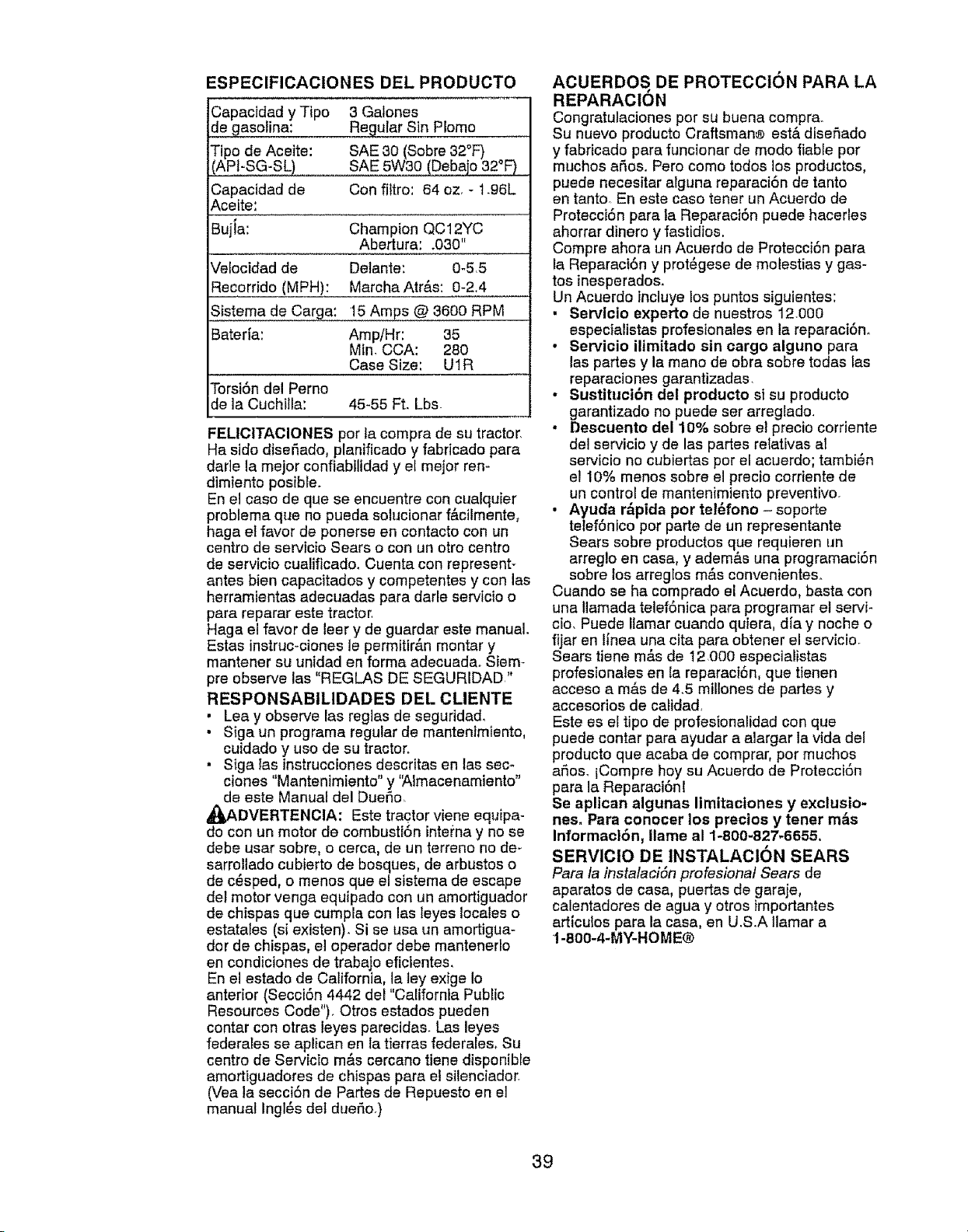
ESPECIFICACIONES DEL PRODUCTO
Capacidad y Tipo 3 Galones
de gasolina: Regular Sin P!omo
Fipo de Aceite: SAE 30 (Sobre 32°F)
APFSG-SL) SAE 5W30 (Debajo 32°F)
Capacidad de Con filtro: 64 oz. + 1+96L
Acefte:
Bujia: Champion QC12YC
Abertura: .030"
Vefocidad de Detante: 0-5.5
Recorrido (MPH): MarchaAtr&s: 0-2.4
S_.istemade Carga! 15 Amps @ 3600 RPM
Bater[a: Amp/Hr: 35
Min. CCA: 280
Case Size: U1R
Torsi6n del Perno
de la Cuchilla: 45-55 Ft. Lbs.
FELICITACIONES por ]a compra de su tractor.
Ha sido diseSado, planificado y fabricado para
darle la mejor conflabiltdad y el mejor ren-
dimiento posible+
En el caso de que se encuentre con cualquier
problema que no pueda solucionar f&cilmente,
haga el favor de ponerse en contacto con un
centro de servicio Sears o con un otro centro
de servicio cualificado, Cuenta con represent+
antes bien capacitados y competentes y con las
herramientas adecuadas para dade servicio o
para reparar este tractor,
Haga el favor de leer y de guardar este manual,
Estas instruc-ciones le permitirAn montar y
mantener su unidad en forma adecuada+ Siem+
pre observe las "REGLAS DE SEGURIDAD."
RESPONSABILIDADES DEL OLIENTE
• Lea y observe las reglas de seguridad,
• Siga un programa regular de mantenimiento,
cuidado y uso de su tractor+
• Siga Ias instruccienes descritas en las sere
clones "Mantenimiento" y 'Almacenamiento"
de este Manual del DueSo.
_DVERTENCIA: Este tractor viene equipa-
do con un motor de cembusti6n intema y no se
debe usar sobre, o cerca, de un terreno no de+
sarrollado cubierto de bosques, de arbustos o
de c6sped, o menos qua el sistema de escape
del motor venga equipado con un amortiguader
de chispas qua cumpla con las leyes locales o
estatales (sJ existen). Si se usa un amortigua-
dor de chispas, el operador debe mantenerlo
en condictones de trabajo eficientes,
En el estado de California, la toy exige Io
anterior (Secct6n 4442 del "Catifomia PubLic
Resources Code"). Otros estados pueden
contar con otras leyes parecidas. Las leyes
federales se aplican en la tierras federales+ Su
centro de Servicio m&s cercano tiene disponible
amortiguadores de chispas para el silenciador+
(Yea la secci6n de Partes de Repuesto en el
manual Ingl6s del due5o+)
ACUERDOS DE PROTECCION PARA LA
REPARACION
Congratulaciones por su buena compr&
Su nuevo producto Craftsman® est& disefiado
y fabricado para funcionar de modo liable por
muchos afios. Pero come todos los productos,
puede necesitar alguna reparaci6n de tanto
en tanto En este caso tener un Acuerdo de
Protecci6n para la Reparaci6n puede hacerles
ahorrar dinero y fastidios.
Compre ahora un Acuerdo de Protecci6n para
la Reparaci6n y prot_gese de molestias y gas-
tos inesperados.
Un Acuerdo incluye los puntos siguientes:
• Servlcio experto de nuestros 12000
especialistas profesionales en la reparaci6n,
• Servicio iltmitado sin cargo alguno para
las partes y la mano de obra sobre todas las
reparaciones garantizadas,
• Sustituci6n del producto si su producto
garantizado no puede set arregtado.
• Descuento del 10% sobre el precio corriente
del servicio y de las partes relativas a_
servicio no cubiertas por el acuerdo; tambi_n
el 10% menos sobre el precio cerriente de
un control de mantenimiento preventivo+
• Ayuda r_pida por tel6fono - soporte
telefonico por parte de un representante
Sears sobre productos que requieren un
arreglo en casa, y adem&s una programaci6n
sobre los arregIos m&s convenientes.
Cuando se ha comprado el Acuerdo, basta con
una Ilamada telef6nica para programar el servi-
cio. Puede Ilamar cuando quiera, dia y noche o
fijar en linea una cita para obtener el servicio.
Sears tiene m_,s de 12.000 especialistas
profesionales en la reparaci6n, que tienen
acceso a m&s de 4.5 miIIones de partes y
accesorios de catidad,
Este es el tipo de profesionalidad con que
puede contar para ayudar a alargar la vida del
producto que acaba de comprar, pot muchos
argos+lCompre hoy su Acuerdo de Protecci6n
para la Reparaci6nt
Se aplican algunas limitaciones y exclusio-
nes. Para conocer los prectos y tener m&s
Informacl6n, llama al 1-800-827-6655.
SERVICIO DE INSTALACtON SEARS
Para la instalaciSn profesional Sears de
aparatos de casa, puertas de garaje+
calentadores de agua y otros importantes
articules para la casa, en U.S+A tlamar a
1-8OO-4-MY-HOME@
39
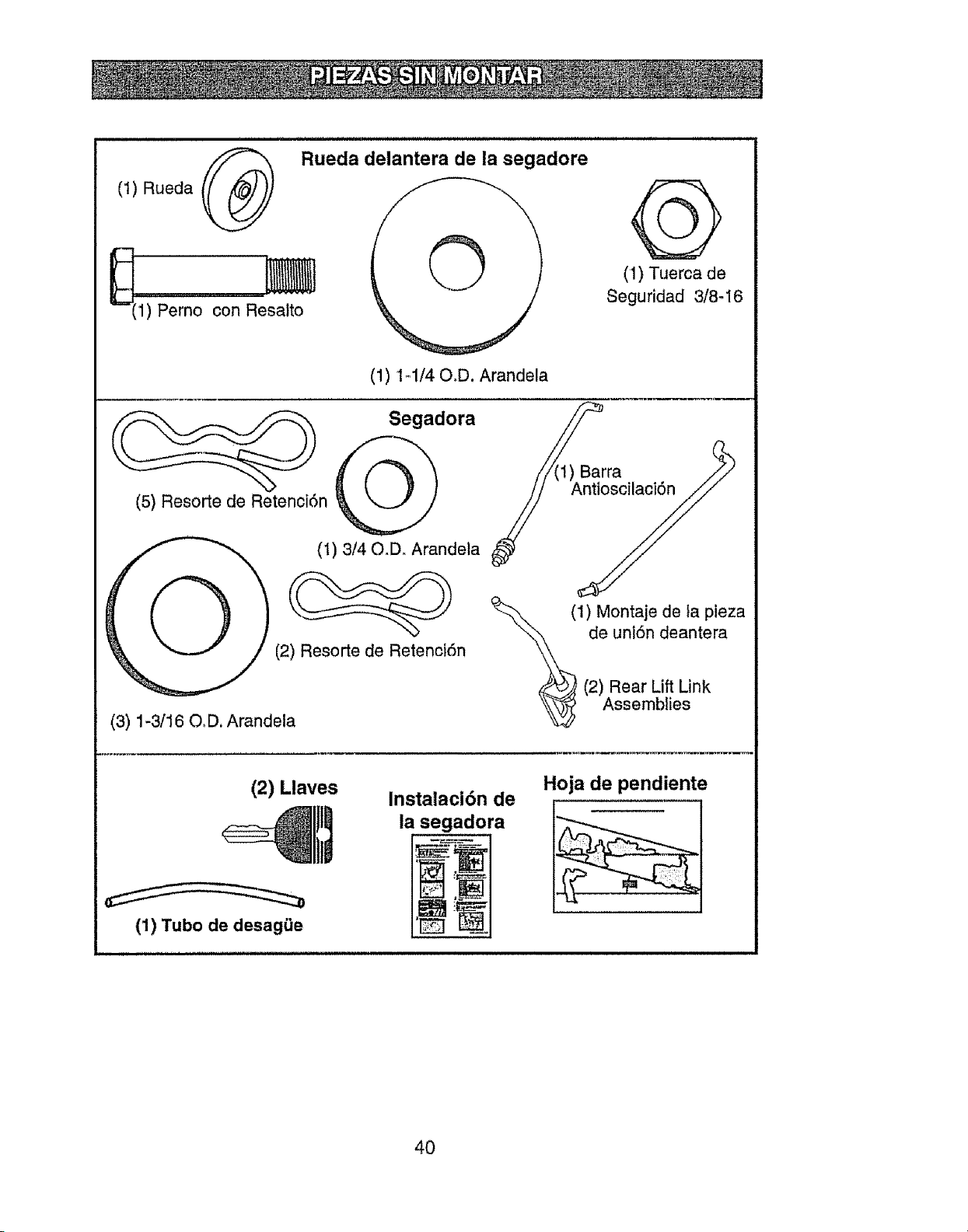
(t) Rueda (_
_(1) Perno con Resa_to
Rueda delantera de la segadore
(1) 1_1/40,D. Arandela
@
(1) Tuerca de
Seguridad 3/8-16
Segadora
(5) Resorte de Retenci6n _O/)
(1) 3/40_D. Arandela
(2) Resorte de Retenci6n
(3) 1-3/16 O,D. Arandela
(1) Montaje de ta pieza
de uniSn deantera
(2) Rear Lift Link
Assemblies
(2) Llaves
Instalaci6n de
la segadora
Hoja de pendiente
(1) Tubo de desagiJe
40
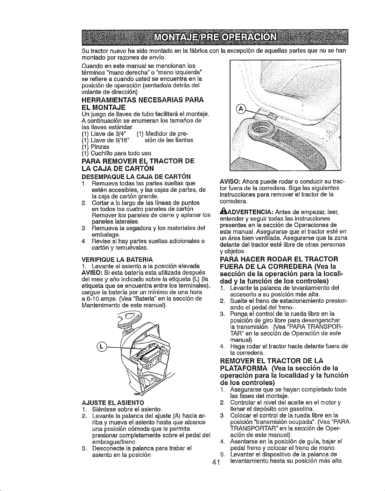
Su tractor nuevo ha sido montado en ta f&brica con la excepct6n de aquellas partes que no se hen
montado por razones de env{o_
Cuando en este manual se mencionan los
t6rminos "mano derecha" o "mano izquierda"
se refie_e a cuando usted se encuentra en la
posici6n de operaci6n (sentado/a detr_.s de!
volante de direcci6n)
HERRAMIENTAS NECESARIAS PARA
EL MONTAJE
Un juego de llaves de tubo facilitar& el montaje_
A continuaci6n se enumeran los tamafios de
las Ilaves est&ndar.
(1) Llave de 3/4" (1) Medidor de pre-
(1) Llave de 9/16" si6n de las Ilantas
(1) Pinzas
(1) Cuchillo para todo uso
PARA REMOVER EL TRACTOR DE
LA CAJA DE CARTON
DESEMPAQUE LA CAJA DE CARTON
1. Remueva todas las partes sueltas qua
est6n accesibles, y las cajas de partes, de
la caja de cart6n grande.
2. Cortar a lo largo de tas lineas de puntos
en todos los cuatro paneles de cart6n
Remover los panetes de cierre y aplanar los
paneles laterales.
3 Remueva la segadora y los materiales del
embalage.
4 Revise si hay partes sueitas adicionales o
cart6n y remu6valas.
VERIFIQUE LA BATERIA
1,_ Levante el asiento ala posici6n elevada
AVISO: Siesta baterfa esta utilizada despu_s
del mes y aSo indicado sobre la etiqueta (L) (la
etiqueta qua se encuentra entre los terminales),
cargue ta bateria por un mlnimo de una hora
a 6-10 amps, (Vea "Bateria" en la secci6n de
Mantenimento de este manual),
AJUSTE EL ASIENTO 2
1. Si6ntese sobre el asiento,
2_ Levante la palanca del ajuste.(A) hacia ar- 3
riba y mueva el asiento haste que alcance
una posici6n c6moda que le permita
presionar completamente sobre el pedal del
embrague/freno 4.
& Desconecte la palanca pare trabar et
asiento en la posici6n 5.
41
AVISO: Ahora puede rodar o conducir su trac-
tor fuera de ta corredera Siga tas siguientes
instrucciones pare remover el tractor de la
corredera.
_ADVERTENOIA; Antes de empezar, leer,
entender y seguir todas las tnstrucciones
presentes en la secci6n de Operaciones de
este manual, Asegurarse que el tractor est_ en
un _.rea bien ventilada. Asegurarse qua la zona
detante det tractor est6 libre de otras personas
y objetos.
PARA HAOER RODAR EL TRACTOR
FUERA DE LA CORREDERA (Yea la
seccibn de la operacibn pare la locali-
dad y la funcibn de los controles)
1. Levante la palanca de levantamiento del
accesorio a su posici6n mAs alta.
2o Suelte el franc de estacionamiento presion-
ando el pedal del franc,
3. Ponga et control de la rueda libre en la
posici6n de giro libre pare desenganchar
la transmisi6n, (Vea "PARA TRANSPOR-
TAR" en la secci6n de OperaciSn de este
manual).
4. Hage rodar el tractor hacia delante fuera de
ta corredera
REMOVER EL TRACTOR DE LA
PLATAFORMA (Vea la seccibn de la
operaci6n pare la localidad y la funci6n
de los controles)
1. Asegurarse qua se hayan completado toda
las fases del montajeo
Controlar el nivel del aceite en el motor y
Ilenar et dep6sito con gasotina,
Colocar el control de la rueda libra en la
posiciSn "transmisiSn ocupada", (Vea "PARA
TRANSPORTAR" en {a secci6n de Oper-
aci6n de este manual).
Asentarse en le posici6n de gu{a, bajar el
pedal freno y colocar el franc de mano.
Levantar el dispositivo de la palanca de
levantamiento haste su postci6n m&s alte
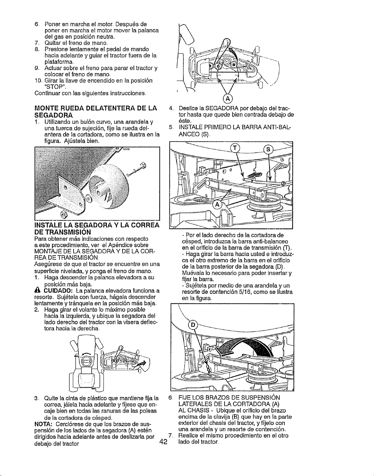
6, PonerenmarchaelmotorDespu_sde
ponerenmarchaelmotormoverlapalanca
delgasenposici6nneutra.
7, Quitarelfrenodemano,
8+ PresionelentamenteeEpedalde mando
haciaadelantey guiareltractorfueradeta
plataforma,
9, Actuarsobreelfrenoparapararel tractory
colocarelfrenodemano.
10.GirarLaIlavedeencendidoenlaposici6n
"STOP",
Continuarconfasslguientestnstrucciones+
MONTE RUEDA DELATENTERA DE LA
SEGADORA
1, Utilizando un bul6n curvo, una arandela y
una tuerca de sujeci6n, fije la rueda del-
antera de la cortadora, como se ilustra en la
figura. AjOstela bien+
4+ Deslice Ia SEGADORA pot debajo del trac-
tor hasta qua quede bten centrada debajo de
_ste+
5, INSTALE PRtMERO LA BARRA ANTI-BAL-
ANCEO (S).
INSTALE LA SEGADORA Y LA CORREA
DE TRANSMISlON
Para obtener m&s indicaciones con respecto
a este procedimiento, vet el Ap_ndice sobre
MONTAJE DE LA SEGADORA Y DE LA COR-
REA DE TRANSMISION
Asegt'Jrese de que el tractor se encuentre en una
superficie nivelada, y ponga el freno de mano,
1+ Haga descender la paIanca elevadora a su
posici6n m&s baja°
CUIDADO: La patanca elevadora funciona a
resorteo Suj_tela con fuerza, h&gala descender
lentamente y tr_.nquela en la posici6n m&s baja+
2. Haga girar el volante lo maximo posible
hacia la izquierda, y ubique la segadora del
lado derecho del tractor con la visera deflec-
tora hacia la derecha+
- Per el tado derecho de la cortadora de
c6sped, introduzca la barra anti-balanceo
en el orificio de la barra de transmisi6n (T)+
- Haga girar la barra hacia usted e introduz-
ca el otro extremo de la barra en el orificio
de la barra posterior de la segadora (D).
Mu_vala to necesario para poder insertar y
fijar la barra+
- Suj6tela por medio de una arandela y un
resorte de contenci6n 5/16, como se ilustra
en la figura.
3. Quite la clnta de pl&stico qua mantiene fija la
correa, j&lela hacia adelante y fiJese qua en-
caje bien en todas las ranuras de ias poleas
de la cortadora de c6spe&
NOTA: Cerci6rese de que los brazes de sus+
pensi6n de los lados de la segadora (A) est_n
dirigidos hacia adelante antes de deslizarla por
debajo del tractor
6r FIJE LOS BRAZOS DE SUSPENSION
LATERALES DE LA CORTADORA (A)
AL CHASIS " Ubique el orificio del brazo
encima de la ciavija (B) qua hay en la parte
exterior del chasis dei tractor, y fijelo con
una arandela y un resorte de contenci6n,
7. Realice el mismo procedimiento en et otro
42 lado del tractor,
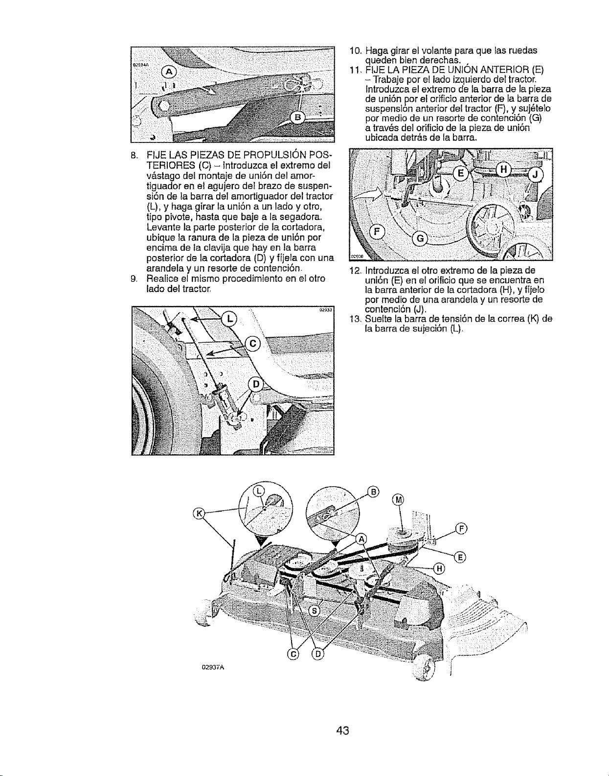
8_ FIJELASPIEZASDEPROPULSIONPOS-
TERIORES(C)- tntroduzcaelextremodel
v#,stagodelmontajedeuni6ndelamor-
figuador en et agujero det brazo de suspen-
si6n de la barra de1amortiguador del tractor
(L), y haga girar la uni6n a un lado y otro,
fipo pivote, hasta que baje a la segadora°
Levante la parte posterior de la cortadora,
ubique la ranura de la pieza de uni6n por
encima de la clavija que hay en la barra
posterior de la cortadora (D) y fijela con una
arandela y un resorte de contenci6n.
9. Realice el mismo procedimiento en el otto
lado clel tractor.
10. Haga girar el volante para que Ias ruedas
queden bien derechas. ,
11. FIJE LA PIEZA DE UNION ANTERIOR (E)
-Trabaje por el lado izquterdo deetractor_
lntroduzca el extremo de la barra de la pieza
de union por el orfficio anterior de la barra de
suspension anterior deetractor (F), y suj6telo
por medio de un resorte de contencio'n (G)
a trav6s det orificio de la pieza de unLon
ubicada detr&s de la barra_
12_Introduzca el otro extremo de la pieza de
uni6n (E) en el orificio que se encuentra en
la barra anterior de la cortadora (H), y fijelo
por medio de una arandela y un resorte de
contenct6n (J).
13_Suelte la barra de tensi6n de la correa (K) de
la barra de sujeci6n (L).
02937'A
43
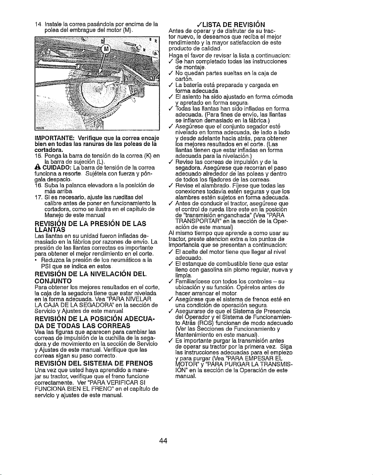
14 lnstale la correa pas&ndola por encima de la
po]ea del embrague del motor (M),
IMPORTANTE: Verifique que la correa encaje
bten en todas las ranuras de las poleas de la
cortadora.
15, Ponga la barra de tensi6n de la correa (K) en
la barra de sujeciSn (L).
CUIDADO: La barra de tensiSn de la correa
funciona a resorte Suj_tela con fuerza y pSn-
gala despacio,
16. Suba la palanca elevadora a la posiciSn de
mas arnDa_
17. Si es necesario, ajuste las rueditas del
calibre antes de poner en funcionamiento la
cortadora, como se ilustraen el capitulo de
Manejo de este manual
REVISION DE LA PRESlON DE LAS
LLANTAS
Las itantas en su unidad fueron infladas de-
masiado en la f&brica por razones de env{o_ La
presi6n de las Ilantas correctas es importante
para obtener el mejor rendimiento en el corte.
• Reduzca la presi6n de los neum_.ticos a ia
PSI que se indica en estos
REVISION DE LA NIVELAOION DEL
CON JUNTO
Para obtener los mejores resultados en et corte,
la caja de {a segadora tiene que estar ntvelada
en la forma adecuada, Vea "PARA NIVELAR
LA CAJA DE LA SEGADORA" en la secci6n de
Servicio y Ajustes de este manual.
REVISION DE LA POSlCiON ADECUA-
DA DE TODAS LAS CORREAS
Vea las figuras que aparecen para cambiar las
correas de impuisi6n de la cuchilla de la sega-
dora y de movimiento en la secci6n de Servicio
y Ajustes de este manual. Verifique que las
correas s!gan su paso eorrecto
REVISION DEL SlSTEMA DE FRENOS
Una vez que usted haya aprendido a mane-
jar su tractor, verifique que el freno funcione
correctamente, Ver "PARA VERIFICAR SI
FUNCIONA BtEN EL FRENO" en el cap{tulo de
servicio y ajustes de este manual.
,ILISTA DE REVISI(_N
Antes de operar y de disfrutar de su trac-
tor nuevo, le deseamos que reciba el mejor
rendimiento y la mayor satisfaccion de este
producto de calidad.
Haga el favor de revisar la lista a continuacion:
,I Se han compfetado todas las instrucciones
de montaje.
J No quedan partes sueltas en la caja de
carton.
v" La bateria est& preparada y cargada en
forma adecuada-
/ El asiento ha sido ajustado en forma c6moda
y apretado en forma segura
,/Todas las Ilantas han sido infladas en forma
adecuada. (Para fines de envio, las Ilantas
se inflaron demasiado en la f&brica.)
•/ AsegQrese que el conjunto segador est_
nivelado en forma adecuada, de lado a lado
_odesde adetante hacia atr&s, para obtener
s mejores resultados en el corte, (Las
Iiantas tienen que estar infEadasen forma
adecuada para la nivelaci6n.)
J Revise las correas de impulsi6n y de la
segadora, AsegQrese que recorran el paso
adecuado alrededor de las poleas y dentro
de todos los fijadores de las correas.
J" Revise el alambrado. Fijese que todas las
conexiones todav{a esten seguras y que los
alambres est_n sujetos en forma adecuada.
,/Antes de conducir el tractor, asegQrese que
el control de rueda libre este en la posicion
de '_ransmisi6n enganchada" (Vea "PARA
TRANSPORTAR" en la secclon de la Oper-
actSn de este manua{)
AI mismo ttempo que aprende a come usar su
tractor, preste atencion extra a los puntos de
importancia que se presentan a conttnuacion:
v_ El aceite del motor tiene que liegar al nivel
adecuado,
,/E1 estanque de combustible tiene que estar
lieno con gasolina sin plomo regular, nueva y
limpia,
•/ Famlliarlcese con todos Ios controles - su
ubicaci6n y su funci6n_ Op6relos antes de
hacer arrancar el motor.
,/Asegt_rese cJueel sistem,a de frenos est_ en
una condition de operacion segura,
v" Asegurarse de que el Sistema de Presencia
del Operador y el Sistema de Functonam}en-
to Atr&s (ROS)funcionan de modo adecuado
(Ver las Secciones de Funcionamiento y
Mantenimiento en este manual).
¢" Es importante purgar Ia transmisiSn antes
de operar su tractor por la pdmera vez. Stga
tas instruccionesadecuadas para el empiezo
y para purgar (Vea "PARA EMPESAR EL
MOTOR" y "PARA PURGAR LA TRANSMIS-
ION" en la secci6n de ta Operaci6n de este
manual.
44
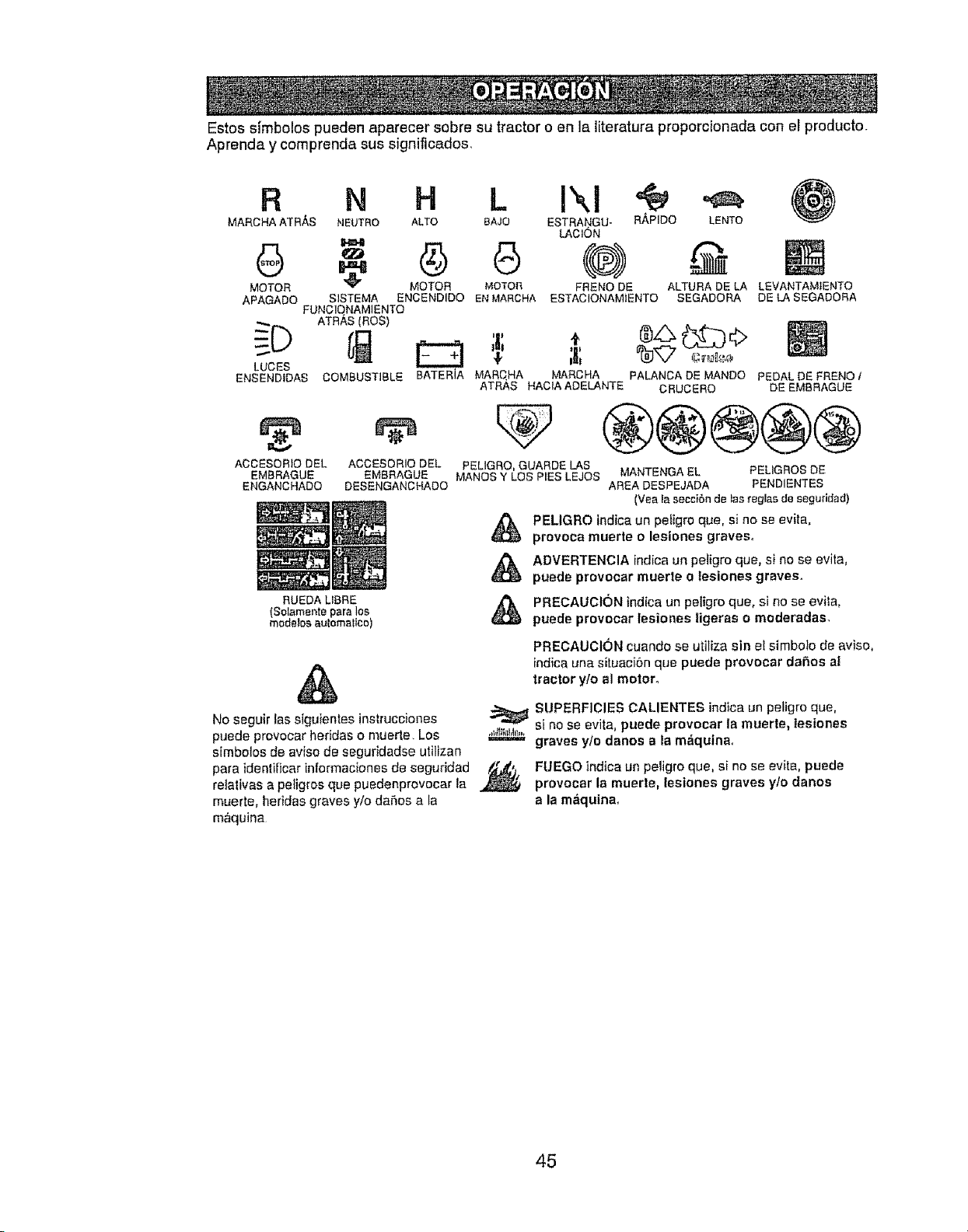
Estos sJmbolos pueden aparecer sabre su tractor o en la literatura proporcionada con el producto.
Aprenda y comprenda sus significados,
R N H L
MARCHA ATRAS NEUTRO ALTO 8AJO
6
MOTOR _ MOTOR MOTOR
APAGADO S1STEMA ENCENDIDO EN MARCHA ESTACIONAMIENTO
FUNCIQNAMIENTO
ATRAS (ROS)
LUCES
ENSENDIDAS COMBUSTIBLE
ACOESORIO DEL ACCESORIO DEL
EMBRAGUE EMBRAGUE
ENGANCHADO DESENGANCHADO
ESTRANGU- RAPIDO LENTO
LACION
@) @
FRENO DE ALTURA DE LA LEWANTAMIENTO
SEGADORA DE LA SEGADORA
RUEDA LfBRE
(Solamente para los
modelos aulomatlco)
®s(XiDo
BATERJA MARqHA MAROHA PALANCA DE MANDO PEDAL DE FRENO 1
ATRAS HACIAADELANTE CRUCERO DE EMBRAGUE
@®®@@
PELIGRO, GUARDE LAS
MANES Y LOS PIES LEJOS MANTENGA EL PELIGROS DE
AREA DESPEJADA PENDIENTES
(Yea la secciBn de tas reglas de seguridad)
PELIGRO indica un peligro que, si no se evita,
provoca muerte o lesiones graves.
ADVERTENClA indica un peligro que, si no se evita,
puede provocar muerte o lesiones graves.
PRECAUCION indica un peligro que, si no se evila,
puede provocar lesiones |igeras o moderadas.
&
No seguir las siguientes instrucciones
puede provocar heridas o muerte Los .,_a_,_.,,j_=
simbolos de aviso de seguridadse utilizan
paraidentificar informaclonesde seguridad _,j.
relalivas a petigros que puedenprovocar la
muerte, heridas graves y/o dafios a la
m&quina
PRECAUCION cuando se utiliza sin el simbolo de arise.
indicauna situacisn que puede provocar dares al
tractor ylo al mctor_
SUPERFICIES CALIENTES indica un peligro que,
si no se evita, puede provocar la muerte, |esiones
graves yte danes a la m&quinao
FUEGO indica un peligro que, si no se evita, puede
provocar la muerte, lesiones graves ylo danes
a la maqutnao
45
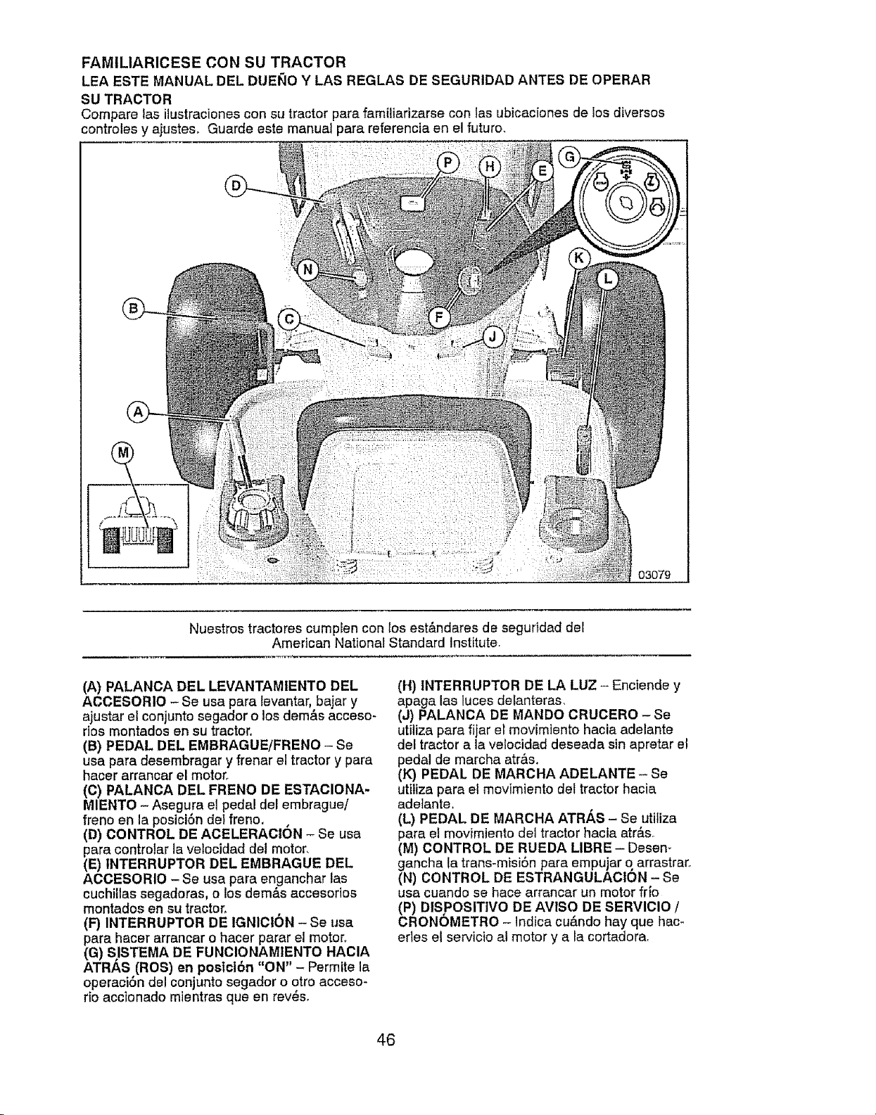
FAMILIARICESE CON SU TRACTOR
LEA ESTE MANUAL DEL DUEI_IO Y LAS REGLAS DE SEGURIDAD ANTES DE OPERAR
SU TRACTOR
Compare las ilustraciones con su tractor para familiarizarse con las ubicaciones de los diversos
controles y ajustes. Guerde este manual pare referencia en el futuro,
03079
Nuestros tractores cumpEen con los estAndares de seguddad del
American National Standard Institute
(A) PALANCA DEL LEVANTAMtENTO DEL
ACCESORIO - Se usa pare levantar, bajar y
ajustar el conjunto segador o los dem&s acceso-
dos montados en su tractor.
(B) PEDAL DEL EMBRAGUE/FRENO - Se
usa pare desembragar y frenar el tractor y para
hacer arrancar el motor.
(C) PALANCA DEL FRENO DE ESTAClONA-
MIENTO - Asegura el pedal del embrague!
freno en le posiciSn del freno,
(D) CONTROL DE ACELERAGION - Se usa
pera controlar la velocidad del motor,
(E) INTERRUPTOR DEL EMBRAGUE DEL
AOOESORIO - Se usa pare enganchar las
cuchillas segadoras, o los demAs accesorios
montados en su tractor,
(F) INTERRUPTOR DE IGNIOI6N - Se usa
para hacer arrancar o hacer parar el motor,.
(G) S/STEMA DE FUNOIONAMIENTO HAOIA
ATRAS (ROS) en postcibn "ON" - Permite la
operaciSn del conjunto segador o otto acceso-
rio accIonado mientras queen reves,
(H) INTERRUPTOR DE LA LUZ- Enciende y
apaga las luces delanteras,
(J) PALANCA DE MANDO CRUOERO - Se
utilize para fijar el movimiento hacia adelante
del tractor ala velocidad deseada sin apretar el
pedal de marcha atr&s.
(K) PEDAL DE MAROHA ADELANTE - Se
utitiza pare el movimiento det tractor hacia
adetante.
(L) PEDAL DE MARCHA ATR_,S - Se utiliza
para el movimiento del tractor hacta atr&s_
(M) CONTROL DE RUEDA LIBRE - Desen-
gancha la trans-misiSn para empujar q arrastraro
(N) CONTROL DE ESTRANGULAClON - Se
usa cuando se hace arrancar un motor frio
(P) DtS POSITIVO DE AVISO DE SERVICIO /
CRONOMETRO - Indica cu_ndo hay que hem
erles ei servicio al motor y a la cortadora_
46
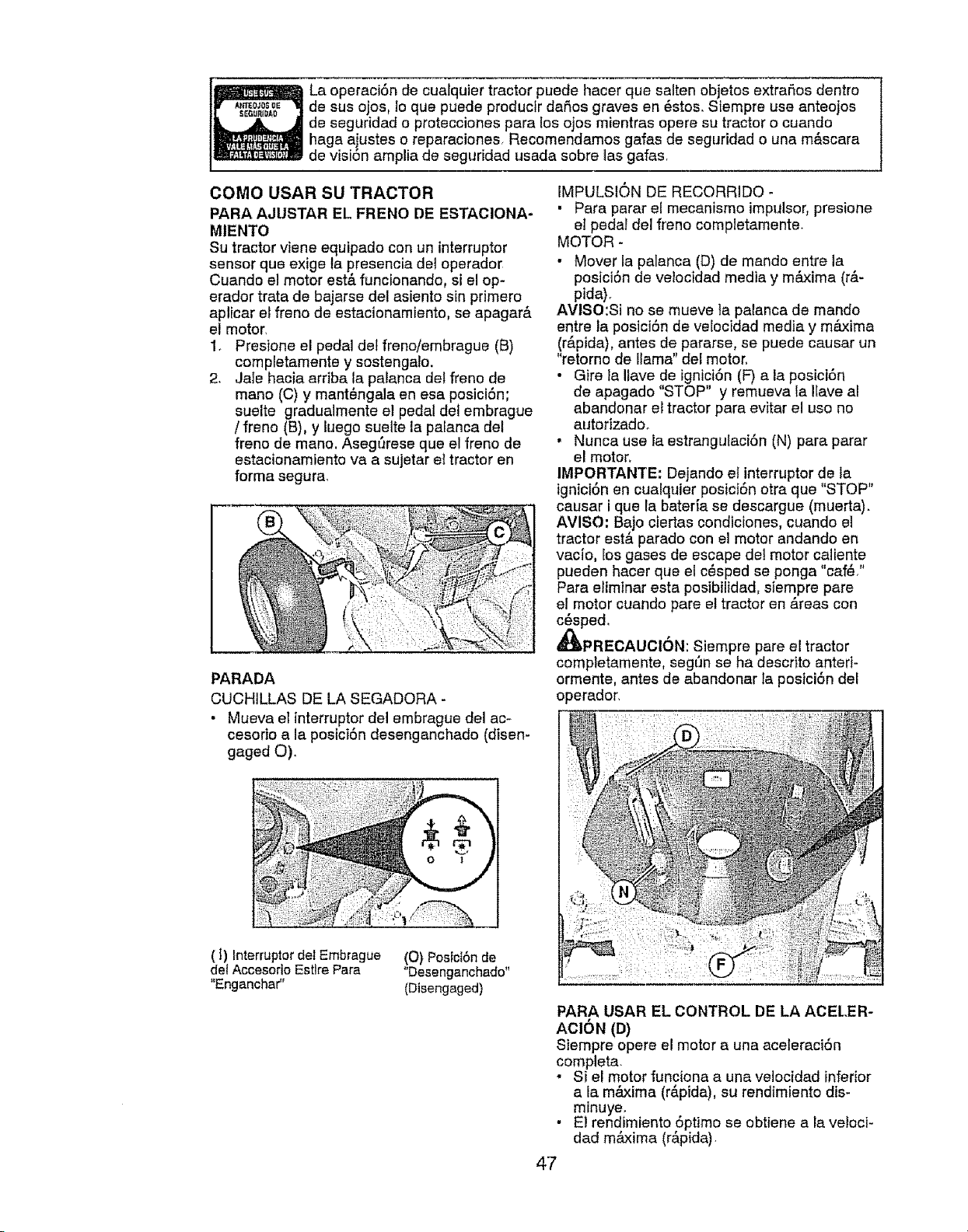
La operaci6n de cualquier tractor puede hacer qua salten objetos extrar_os dentro
de sus ojos, lo que puede productr dahos graves en 6stos. Siempre use anteojos
de seguridad o protecciones para los ojos mientras opera su tractor o cuando
haga ajustes o reparaciones Recomendamos galas de seguridad o una m&scara
de visi6n amplia de seguridad usada sobre lax gafas,
COMO USAR SU TRACTOR
PARA AJUSTAR EL FRENO DE ESTACIONA-
MIENTO
Su tractor viene equipado con un interruptor
sensor qua exige la presencia del operador
Cuando el motor est& funcionando, si el op-
erador trata de bajarse de! asiento sin primero
aplicar el freno de estacionamiento, se apagar&
el motor.
1. Presione el pedal det freno/embrague (B)
completamente y sostengato.
2. Jale hacia arriba la palanca det freno de
mano (C) y mant_ngala en esa posici6n;
suelte gradualmente el pedal det embrague
/ freno (B), y tuego suelte la palanca del
freno de mano. Aseg_rese que el freno de
estacionamiento va a sujetar el tractor en
forma segura.
PARADA
CUCHILLAS DE LA SEGADORA -
• Mueva el interruptor del embrague del ac-
cesorio a la posici6n desenganchado (disen-
gaged O).
,'ii'iiiiii!ii!i!
o "T'/
(f) lnterruptor de! Embrague (O) Poslci6n de
def Accesodo Esttre Para "Desenganchado"
"Enganchar" (Disengaged)
IMPULSION DE RECORRIDO -
• Para parar el mecanismo impulsor, presione
el pedal del freno completamente.
MOTOR-
- Mover la palanca (D) de mando entre la
posici6n de velocidad media y m&xima (r&-
pida).
AVISO:Si no se mueve la palanca de mando
entre la posici6n de velocidad media y m&xima
(r_.pida), antes de pararse, se puede causar un
"retorno de llama" del motor,
• Gire la Iiave de ignici6n (F) a ia posici6n
de apagado "STOP" y remueva la Have al
abandonar el tractor para evitar el uso no
autorizado.
• Nunca use la estrangulaci6n (N) para parar
e! motor,
IMPORTANTE: Dejando el interruptor de la
ignici6n en cualquier posici6n otra que "STOP"
causar i qua la bateria se descargue (muerta).
AVISO: Bajo ciertas condiciones, cuando el
tractor est& parado con el motor andando en
vacJo, los gases de escape del motor caliente
pueden hacer qua el c_sped se ponga "caf_."
Para eliminar esta posibilidad, siempre pare
el motor cuando pare el tractor en &teas con
c_sped,
_IbPRECAUClON: Siempre pare el tractor
completamente, seg_n se ha descrito anted-
ormente, antes de abandonar la posici6n del
operador.
PARA USAR EL CONTROL DE LA ACEL.ER-
ACI6N (D)
Siempre opera el motor a una aceleraci6n
completa.
• Si el motor funciona a una velocidad inferior
a la m&xima (rApida), su rendimiento dis-
minuye.
• E1 rendimiento 6ptimo se obtiene a la vetoci-
dad m&xima (r&pida)
47
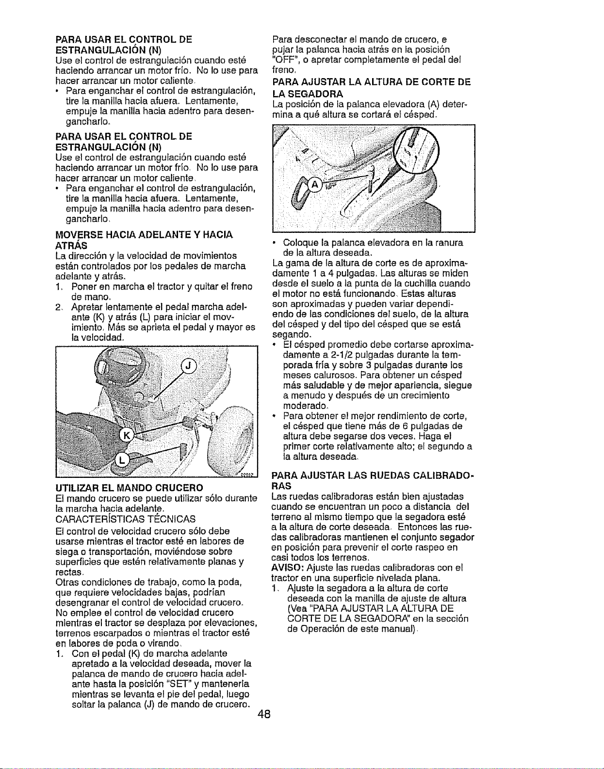
PARA USAR EL CONTROL DE
ESTRANGULACION (N)
Use el control de estrangutaciSn cuando est_
haciendo errancar un motor fr{o, No Io use pare
hacer arrancar un motor caliente.
• Pare enganchar et control de estrangulaci6n,
tire la mani[le hacia efuerao Lentamente,
empuje la manilla hacia edentro pare desem
gancharlo.
PARA USAR EL CONTROL DE
ESTRANGULACtON (N)
Use el control de estranguiaciSn cuando est_
haciendo errancer un motor frfa No Io use pare
hacer arrancar un motor caliente
•Para enganchar el control de estrangulaci6n,
tire te manllla hacia afuera. Lentamente,
empuje la manilla hacia adentro pare desen-
ganchar!o,
MOVERSE HACIA ADELANTE Y HACIA
ATRh, S
La direcciSn y la velocided de movimientos
est_.n controledos per los pedales de marcha
adelante y atr_so
1_ Poner en marche el tractor y quitar el freno
de manoo
2, Apretar lentamente el pedal marcha adel-
ante (K) y atrAs (L) pare iniciar el mov-
imiento, M&s se aprieta el pedal y mayor es
la velocidad.
UTILIZAR EL MANDO CRUCERO
El mando crucero se puede utilizar sSIo durante
la mercha hacia adelante.
CARACTER{STICAS TI_CNICAS
El control de velocidad crucero s61odebe
usarse mientras el tractor est_ en labores de
siege o transportaci6n, movi_ndose sobre
superficies que est_n relattvamente planes y
rectaso
Otras condictones de trabajo, come la poda,
que requiere velocidades bajas, podr{an
desengranar el control de velocidad cruceroo
No empiee el control de velocidad crucero
mientras el tractor se desplaza per elevaciones,
terrenos escarpados o mientras et tractor est_
en iabores de poda o virando,
1. Con et pedal (K) de marcha adelente
apretado ala velocidad deseada, mover ta
palanca de mando de crucero hacia ariel-
ante haste la posici6n "SET" y mantenerta
mientras se levanta el pie del pedal, luego
soltar la pa[anca (J) de mando de crucero.
48
Pare desconectar ei mando de crucero, e
pujar la palanca hacia atr&s en Ia posici6n
"OFF", o apretar completamente el pedal del
freno,
PARA AJUSTAR LA AI TURA DE CORTE DE
LA SEGADORA
La posiciSn de ia palanca etevadora (A) deter-
mina a qu6 altura se cortar& et c6sped.
• Coloque la palanca e[evadora en la ranura
de la a]tura deseada.
La game de la altura de corte es de aproxima-
damente ! a 4 pulgadas. Las alturas se miden
desde el suelo ala punta de la cuchi!ia cuando
el motor no est& funcionando, Estas alturas
son aproximadas y pueden verier dependi-
endo de las condiciones de1suelo, de la altura
del c6sped y del tipo del c_sped que se est&
segando.
. E! c_sped promedio debe cortarse aproxima-
damente a 2-1/2 pulgadas durante la tem-
porada fria y sobre 3 pulgadas durante los
meses calurosos. Para obtener un c6sped
m&s saludable y de mejor apariencia, siegue
a menudo y despues de un crecimiento
moderado.
• Pare obtener el meier rendimiento de code,
el c6sped que tiene m&s de 6 pulgadas de
eltura debe segarse dos veces, Haga el
primer corte reletivamente alto; el segundo a
la altura deseada.
PARA AJUSTAR LAS RUEDAS CALIBRADO-
RAS
Las ruedes calibradoras est&n bien ejustadas
cuando se encuentran un peco a distancie del
terreno al mismo tiempo que le segadora est_
e le altura de corte deseada_ Entonces tas rue-
des calibradoras mentienen el conjunto segedor
en posict6n pare prevenir el corte raspeo en
cesi todos los terrenos.
AMISO: Ajuste las ruedas calibradoras con el
tractor en una superficie nivelede plane.
1. Ajuste la segadore ala altura de corte
deseeda con Lamanilla de ejuste de eltura
(Vea "PARA AJUSTAR LA ALTURA DE
CORTE DE LA SEGADORA" en la secciSn
de Opereci6n de este manual)
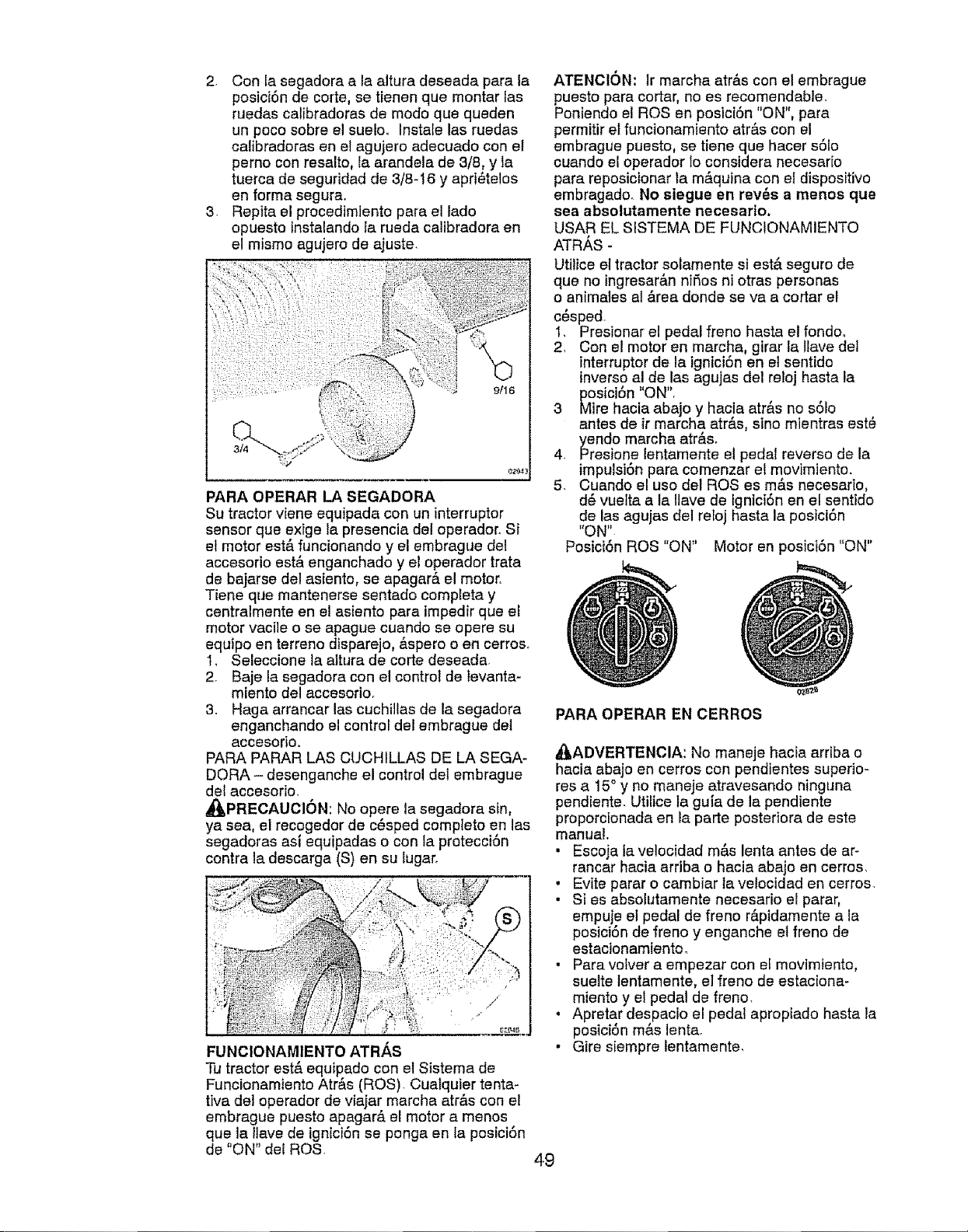
2. ConJasegadoraa laalturadeseadaparala
posici6ndecorte,setienenquemontarlas
ruedascalibradorasdemodoquequeden
unpocosobreel sueio_Instalelasruedas
calibradorasenelagujeroadecuadoconel
pernoconresalto,laarandelade3/8,yla
tuercadeseguridadde3/8-16y apri_telos
en forma segura.
3. Repita el procedimiento para el lado
opuesto instalando la rueda calibradora en
el mismo agujero de ajuste
PARA OPERAR LA SEGADORA
Su tractor viene equipada con un interruptor
sensor que exige la presencia del operador, Si
el motor est& funcionando y el embrague del
accesorio est& enganchado y el operador trata
de bajarse del asiento, se apagar& el motor.
Tiene que mantenerse sentado completa y
centralmente en el asiento para impedir que el
motor vacile o se apague cuando se opera su
equipo en terreno disparejo, &spero o en cerros.
1, Seleccione ta altura de corte deseada.
2. Baje Jasegadora con el control de levanta-
miento del accesorio.
3. Haga arrancar las cuchillas de la segadora
enganchando el control del embrague del
accesorio.
PARA PARAR LAS CUCHILLAS DE LA SEGA-
DORA - desenganche el control del embrague
de{ accesorio,
_IbPRECAUCI6N: No opere la segadora sin,
ya sea, el recogedor de c_sped completo en las
segadoras asi equipadas o con ta protecciSn
contra la descarga (S) en su lugar_
FUNCIONAMIENTO ATR,&.S
Tu tractor est& equipado con el Sistema de
Funcionamiento Atr&s (ROS) Cuatquier tenta-
tiva del operador de viajar marcha atr&s con el
embrague puesto apagar& el motor a menos
que la llave de ignici6n se ponga en la posici6n
de "ON" del ROS.
ATENClON; Jrmarcha atr&s con el embrague
puesto para cortar, no es recomendable.
Poniendo el ROSen posici6n "ON", para
permitir el funcionamiento atr&s con el
embrague puesto, se tiene qua hacer s61o
cuando el operador Io considera necesar[o
para reposicionar ta m&quina con el dispositivo
embragado. No siegue en rev_s a menos que
sea absolutamente necesario.
USAR EL SISTEMA DE FUNCIONAMIENTO
ATR,_S -
Utilice e] tractor solamente si est& seguro de
qua no ingresar&n niSos ni otras personas
o animales al &tea donde se va a cortar el
c_sped.
1, Presionar el pedal freno hasta el fondo,
2, Con el motor en marcha, girar la llave del
interruptor de la igniciSn en et sentido
inverso al de las agujas del reloj hasta la
posici6n "ON",
3 Mire hacia abajo y hac!a arras no s61o
antes de ir marcha atras, sino mientras esL_
yendo marcha atr_s.
4. Presione lentamente el pedal reverso de la
impulsi6n para comenzar el movimiento.
5. Cuando el uso del ROSes m&s necesado,
d_ vuelta a ta Ilave de tgntci6n en el senttdo
de las agujas del reloj basra la posiciSn
"ON"
PosiciSn ROS "ON" Motor en posiciSn "ON"
PARA OPERAREN CERROS
,_ADVERTENCIA: No maneje hacia arriba o
hacia abajo en cerros con pendientes superim
res a 15° y no maneje atravesando ninguna
pendiente. Utilice la guia de la pendiente
proporcionada en la parte posteriora de este
manual,
• Escoja la velocidad m&s lenta antes de ar-
rancar hacia arriba o hacia abajo en cerros,
, Evite parar o cambiar la velocidad en cerros.
• Si es absolutamente necesario el parar,
empuje et pedal de freno r&pidamente a la
posici6n de freno y enganche el freno de
estacionamiento.
• Para volver a empezar con e! movimiento,
suette tentamente, el freno de estaciona-
miento y el pedal de freno,
• Apretar despacio el pedal apropiado hasta la
posiciSn m&s lenta_
• Gire siempre lentamente,
49
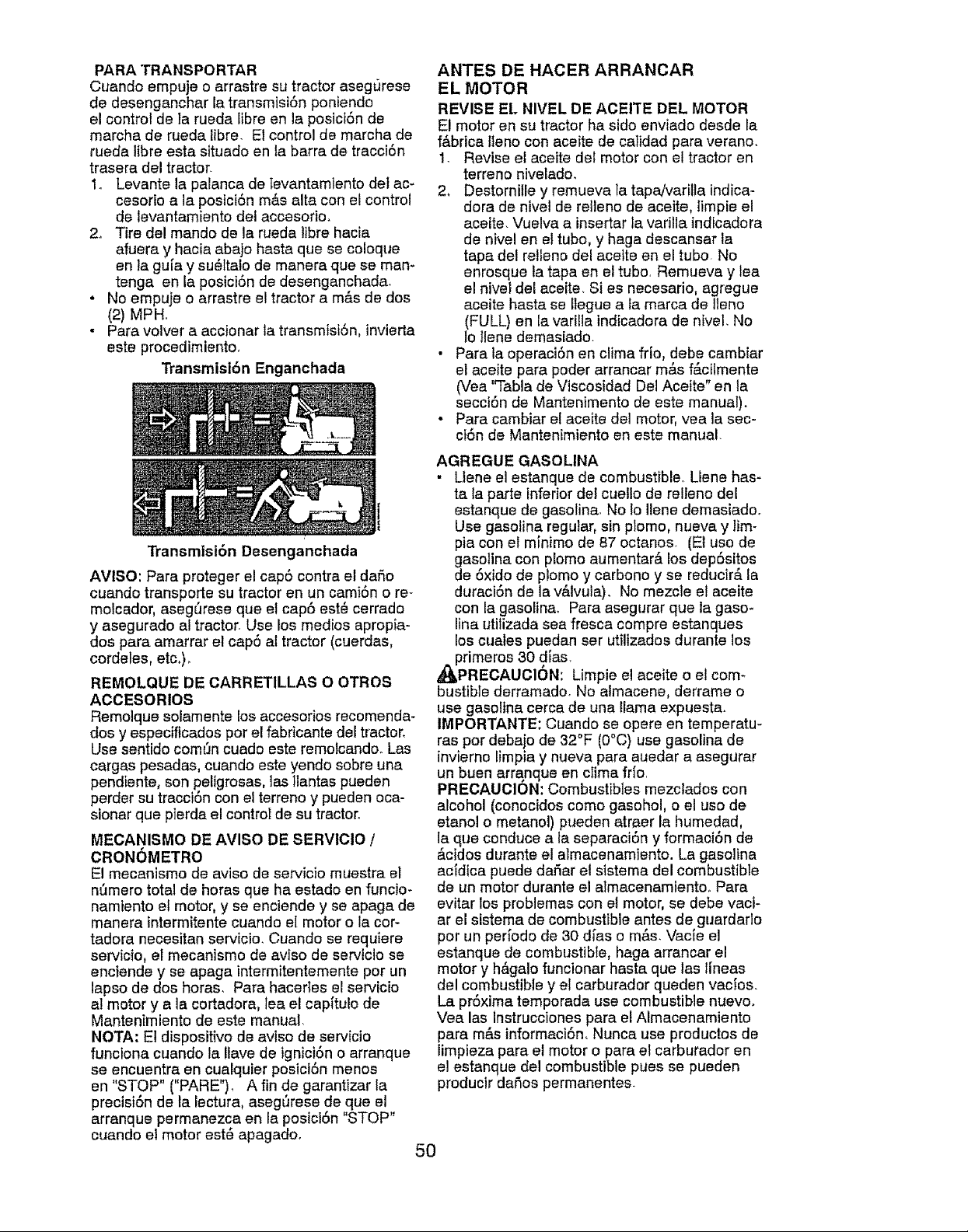
PARA TRANSPORTAR
Cuando empuje o arrastre su tractor aseg_rese
de desengenchar la transmisi6n poniendo
el control de ta rueda libre en la posici6n de
marcha de rueda libre. El control de marcha de
rueda libra esta situado en la barra de tracci6n
trasera del tractor.
1. Levante le paianca de Ievantamiento deI ac-
cesodo ala posici6n m&s alta con el control
de levantamiento del accesofio.
2. Tire del mando de le rueda libra hacie
efuera y hacie abajo haste que se coloque
en la gula y su61talo de menere que se mare
tenga en la posici6n de desenganchada.
. No empuje o arrastre el tractor a m&s de dos
(2) MPH.
• Pare volver a eccionar le transmisi6n, invierta
este procedimiento,
Transmisi6n Enganchada
Transmisi6n Desenganchada
ANTES DE HACER ARRANCAR
EL MOTOR
REVISE EL NIVEL DE ACEITE DEL MOTOR
E! motor en su tractor ha sido enviado desde le
f&brica l_eno con aceite de catidad para verano.
1. Revise el eceite del motor con el tractor en
terreno nivelado.
2, Destornille y remueva la tapa/vadlle lndica-
dora de nivel de relleno de aceite, limpie el
aceite. Vuelve a inserter la vadlla indicadore
de nivel en el tubo, y haga desca.nsar la
tape del relieno del eceite en el tubo. No
enrosque la tapa en el tubo, Remueva y lea
el nivel del aceite. Si es necesario, agregue
eceite haste se llegue ata marca de Ileno
(FULL) en le varilla indicedora de nivel. No
1ollene demasiedo.
• Pare la opereci6n en clima frio, debe cambier
el aceite pare poder arrencar m&s f_cilmente
(Vea "Table de Viscosided Del Aceite" en la
secci6n de Mentenimento de este manual).
* Pare cambiar el aceite del motor, vea la sec-
c}6n de Mantenimiento en este manual.
AVISO: Para proteger el cap6 contra el dafio
cuando transporte su tractor en un cami6n o re-
molcador, aseg_rese que et cap6 est_ cerredo
y asegurado a! tractor. Use los medics apropia-
dos pare amarrar el cap6 al tractor (cuerdes,
cordeles, etc_)_
REMOLQUE DE CARRETILLAS O OTROS
ACCESORIOS
Remolque solamente los accesoriosreccmende-
dos y especificados por el fabdcante del tractor.
Use sentido comSn cuado aste remolcando. Las
carges pesadas, cuendo este yendo sobre una
pendiente, son peligrosas, ]as tlantes pueden
perder su traccl6n con el terreno y pueden oca-
sionar que pierde el controI de su tractor.
MECANISMO DE AVISO DE SERVICIO /
CRONOMETRO
El mecenismo de aviso de servicio muestra el
nt_mero total de horas qua ha estado en funcio-
namiento el motor, y se enciende y se apaga de
manera intermitente cuando el motor o la cor-
tedora necesitan servicio. Cuando se requiere
servicio, el mecanismo de aviso de servlclo se
enciende y se apaga intermitentemente por un
lapso de dos horas. Pare hacerles el servicio
at motor y ala cortadora, lea el cap[tulo de
Mentenimiento de este manuel,
NOTA: Et dispositivo de evlso de servic]o
funclona cuando la !tave de tgnici6n o arranque
se encuentre en cualquier posici6n menos
en "STOP" ("PARE"). A fin de garantizer la
precisi6n de ta lecture, asegl_rese de que el
erranque permanezca en la posici6n "STOP"
cuando el motor est6 apagadoo
AGREGUE GASOLINA
• Ltene el estanque de combustible, Llene has-
te la parle inferiorde! cuetlo de relfeno del
estanque de gasotine_ No Io Ilene demasiado.
Use gasoline regular, sin ptomo, nueva y lim-
pia con el minimo de 87 octanos. (El uso de
gasoline con plomo aumentar& los dep6sitos
de 6xido de piomo y carbono y se reducir_, la
dureci6n de la v&lvula). No mezcle el aceite
con la gasolin& Pare asegurar que la gaso*
line utilizada sea fresca compre estenques
los cuales puedan ser utilizedos durante los
_primeros 30 dies.
PRECAUCION: Limpie el aceite o el com-
bustible derramado. No almecene, derreme o
use gasoline cerca de una llama expuesta.
IMPORTANTE: Cuando se opere en temperatu-
res por debajo de 32°F (O°C) use gasoline de
invierno limpia y nueve pare auedar a asegurar
un buen arranque en clime frio.
PRECAUCION: Combustibles mezctados con
alcohol (conecidos como gasohol, o el uso de
etanol o metanol) pueden atraer la humedad,
la qua conduce ala separaci6n y formeci6n de
&cidos durente el almacenamiento. Le gasolina
acidica puede daSar el sistema del combustible
de un motor durante el atmecenamiento, Pare
evitar los problemas con et motor, se debe vaci-
ar el sistema de combustible antes de guerdarlo
por un per[odo de 30 dies o m&s. Vacte el
estanque de combustibIe, haga arrancar el
motor y hagalo funcionar haste qua las hneas
del combustible y el carburador queden vacfos.
La pr6xima temporada use combustible nuevo.
Vee las instrucciones pare el Almecenemiento
pare m&s informaci6n, Nunce use productos de
limpieze para el motor o pare el carburador en
el estanque del combustible pues se pueden
producir deBos permanentes.
5O
PARA HACER ARRANCAR EL MOTOR
AI hacer arrancar el motor por la primera vez o
si se ha acabado el combustible del motor, se
necesitar& tiempo para el arranque extra para
mover el combustible desde et estanque hasta
et motor
1 Aseg[_rese que el control de rueda libra
este en ta posici6n enganchada
2 Si_ntase en el siil6n en ta posici6n de
operaci6n, suelte el pedal del freno y ponga
el freno de estacionamiento
3 Mueva el embrague del accesorio ala
posici6n desenganchado disengaged
4 Mueva el control de la aceleraci6n ala
posiciSn de r&pidoo
5 Tire el control de estrangulaci6n ala
posiciSn de estrangulaciSn pare et arranque
de un motor frio Para el arrancar un motor
caliente et uso dot control de la estrangu-
laci6n puede qua no sea necesario
AVISO: Antes de arrancar, lea las instruccio-
nes siguientes para el arranque en clima frio y
templado
6 Inserte la tlave en la ignici6n y gire la Have
en el sentido qua giran ]as manilias del retoj
ala posici6n de arranque start, y suelte la
llave tan pronto como arranque el motor
No haga funcionar el arrancador continu-
amente por m#,s de quince segundos por
minuto Si el motor no arranca despu_s de
varios intentaflos, mueva el control de la
estrangulaci6n hac[a adentro, espere unos
cuantos minutos y trate de nuevo Si el mo-
tor sigue sin funcionar, estire del control de
ta estrangulaciSn y trate de nuevo
ARRANQUE CON TEMPO TEMPLADO (50°
Y M/kS)
7. Cuando arranque el motor, empuje el con-
trol de la estrangulaci6n haste que el motor
empiece a funcionar m&s suavemente. Si
el motor empieza a funcionar mal, estire
de] controt de la estrangu]aci6n un poco
pot unos cuantos segundos y entonces
continu@ a empujar lentamente el control
• Los accesorios y el embrague de suefo
ahora puede ser utilizados Si et motor no
acepta esta carga, vuelva a arrancar el motor
para permitide que se caliente por un minuto,
utilizando et estrangulador como descfibido
arriba
ARRANQUE CON TEMPO FRiO (50° Y
MENOS)
7 Cuando arranque el motor, empuje lenta-
monte el control de la estrangulaci6n hacia
adentro hasta qua el motor empiece a
funcionar suavemente° Siga empuj_,ndolo
poco a poco permitiendo qua el motor acepte
pequer_os camblos de velocidad y carga,
haste que este completamente hacia aden-
tro 81 el motor empieza a funcionar mal, as-
tire def control de la estrangulaci6n un poco
por unos cuantos segundos y contin0e a
empujar el control hac{a adentro Esto puede
requerir qua el motor se caliente por unos
cuantos minutos, depende de la temperature
CALENTAMIENTO PARA LA TRANSMtSION
AUTOMATICA
Antes de conducir ta unidad en un tiempo frfo,
la transmisiSn debeser catentada como las
instrucciones sigL_ientes:
1 Aseg_rese qua el tractor este situado en
una superficie nivelada
2, Alivie e_freno de estacionamiento y deje
qua el freno vue]va ala posici6n de oper-
aci6n
3 Permita que la transmisi6n se ca]lento
durante un minuto Esto puede ser echo du-
rante el tiempo de calentamiento del motor
• Los accesoflos pueden ser uti]izados durante
el periodo del recalentamiento deI mo-
tor despu6s que la transmisi6n halla sido
calentada y puede requefir qua el control de
_aestrangutaci6n sea estirado un poco
AVI80: Si se encuentra a touche altura (sobre
3000 pies) o en clime fr[o (par debajo de 32°F
[0°C]), la mezcla del combustible del carburador
debeser ajustada pare el major rendlmiento
del motor (Vea "PARA AJUSTAR EL CARBU-
RADOR" en fa secc[6n de Servicio y Ajustes de
este manual)
¢
RURGAR LA TRANSMISION
_,PRECAUCION: Nunca enganche o desen-
ganche la palanca de! control de rueda libre
cuando el motor esta funcionando
Para asegurar ]a operaci6n y ejecuci6n adec-
uada, es recomendado qua ta transmisl6n sea
purgada antes de operar el tractor para la prim-
era vez Este proceso remover& cualquier aire
adentro de la transmisl6n qua se halla formado
durante el transporte de su tractor
IMPORTANTE: Si por acaso su transmisi6n
debe ser removtda pare servtcio o reemplazo,
debeser purgada despu6s de la reinstalaciSn y
antes de operar el tractor.
1. Para mayor seguridad, ubique el tractor
en una superficie nivelada, despejada de
cualquier objeto y abierta, con el motor
apagado y el freno de mano puesto,
2 Desenganche latransmisiSn poniendo el
control de rueda libre en la posici6n de
desenganchado (Vea "PARA EL TRANS-
PORTE" en esta secciSn de este manua!),
51
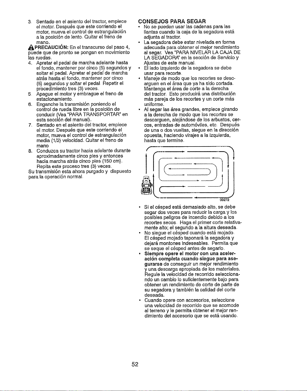
3. Sentado en et asiento det tractor, empiece
el motor. Despu_s que este corriendo el
motor, mueva el control de estrangulaci6n
a la posic[6n de lento Quitar el freno de
mano.
_PRECAUCI6N: En el transcurso del paso 4.
puede que de pronto se pongan en movimiento
las ruedas,
4. Apretar el pedal de marcha adelante hasta
el fondo, mantener por cinco (5) segundos y
sottar el pedal Apretar el pedal de marcha
atrAs haste el fondo, mantener por cinco
(5) segundos y soitar el pedal Repetir et
procedlmiento tres (3) veces.
5. Apague el motor y embrague el freno de
estacionamiento,
6, Enganche la transmist6n poniendo el
control de rueda libra en la posici6n de
conducir (Vea "PARA TRANSPORTAR" en
esta secci6n del manual).
7, Sentado en el asiento del tractor, empiece
el motor. Despu_s que este corriendo el
motor, mueva el control de estrangulaci6n
media (1/2) velocidado Quitar el freno de
mano
8. Conduzca su tractor hacia adelante durante
aproximadamente cinco pies y entonces
hacia marcha atrAs oinco pies (150 cm)_
Repita este proceso tres (3) veces.
Su transm]si6n esta ahora purgado y dispuesto
pare la operaci6n normal.
CONSEJOS PARA SEGAR
• No se pueden usar las cadenas para las
llantas cuando ta caja de ]a segadora estA
adjunta al tractor.
• La segadora debe ester nivelada en forma
adecuada pare obtener el mejor rendimlento
a] segar., Vea "PARA NIVELAR LA CAJA DE
LA SEGADOP_' en ta secci6n de Servicio y
Ajustes de este manual.
• El Iado izquierdo de la segadora se debe
usar para recorte.
• Maneje de modo qua tos recortes se desc-
arguen en el Area qua ya ha sido cortada.
Mantenga el Area de corte a la derecha
del tractor, Esto producirA una distribuciSn
mAs pareja de los recortes y un corte mas
uniforme.
• AI segar las Area grandes, empiece girando
a ta derecha de modo qua los recortes se
descarguen, alejAndose de los arbustos, cer-
cos, entradas de autom6viles, etc. Despu6s
de una o dos vueltas, siegue en la dfrecci6n
opuesta, haciendo virajes a la izquierda,
]
hasta que termine,
f
.....
1
00272
• Si el c6sped estA demasiado alto. se debe
sager dos veces para reducir la carga y los
posibies peligros de incendio debido a los
recortes secos Haga el primer corte relativa-
mente alto; el segundo a la altura deseada.
• No siegue el c6sped cuando estA mojado.
El c_sped mojado taponarA la segadora y
dejarA montones tndeseables. Permita que
se seque el c_sped antes de segarlo,
• Siempre opere el motor con una aceler-
act6n completa cuando siegue para ase-
gurarse de conseguir un mejor rendimiento
y una descarga apropiada de tos mater[ales.
Regule la velocidad de recorrido se]ecciona-
ndo un cambio Io suficientemente bajo pare
obtener un rendimiento de corte de parte de
su segadora y tambi6n la calidad del corte
deseada_
• Cuando opere con accesofios, seleccione
una velocidad de recorrido que se acomode
a] terreno y le permita obtener el mejor ren-
dimiento del accesorio que se est& usando.
52
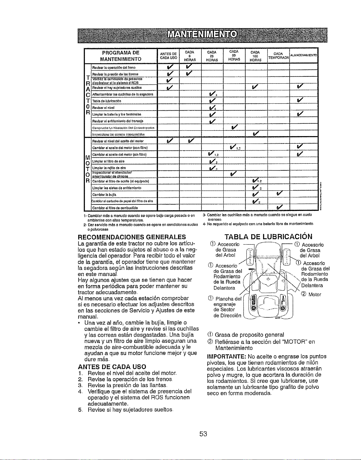
PROGRAMA DE NANTESDE CADA
MANTENIMIENTO CADA U$O B
HOP,AS
Revisor la opemd6n del f_OnO V e V _
v" v'
T Revisor Ir_p_esl6n de lira Itonlao
V6rllI_z Ii] eommenda de pr6sonca V r
g d_°,.d_-_°_,_.6_'ralaurat le glstorn_ d ROS
T _bt.do]ubd¢l_d6n
0 Revloarel nJvel
a umpforlaboterf_y tor_torm_noleo.......
Revloat _l enfdam_nto dol _mnsBje
CADA CADA CADA CADA ALMACENAMIENTO
?.5 60 100 TEMPORADA
HORAS HORA8 HORA8
i ........ 1
v'_
v' v'
v'
v"
Rev!_aralnlv_,Idolattila dol moto_ I_ I_
Cambt_r ol 8,co}todes meier (con ftllro)
M Cambror 01OCottedel mofor (sitt,fltt_o)
O UmpI_ el flt_'o de Btm ...........
m UmpI_r {ateI_t_r_de _re
In_,pec_lonat B{ _lonc_or/
0 8modlo_dof de chtooBo
R cambfar el fliltod0 OCOJIO{O1oqu_po,do)
UmpI_ le_ _ot_ de onff_amlen_o
Oamb_or Io buJt_
_atr_blo,rel Caducho de p_pel dolfi_m do alto
Oomblor el fill,tode combustible
_oOamblatra_sB menudo cuandoBe oporobalocargapesada o on 3-
ambIBnte4_con altostempa_'atura8.
2- Dor sorvic{o m_8 B merludo cuendo 80 oporo o_ condi_iones BUCIB8 4-
o poivoro_as
RECOMENDACIONES GENERALES
La garantta de este tractor no cubre los articu-
los que han estado sujetos al abuso o a la neg-
ligencia del operador, Para recibir todo el valor
de la garantia, el operador tiene que mantener
la segadora seg_n los instruccionesdescritas
en este manual.
Hay algunos ajustes que se tienen que hacer
en farina ped6dica para poder mantener su
tractor adecuadamente.
AI menos una vez cada estaci6n comprobar
si es necesario efectuar los adiustes descfitos
en los secciones de Servicio y Ajustes de este
manual.
• Unavez al a_o, cambie la buj[a, limpie o
cambie el filtro de aire y revise silas cuchiilas
y {as correas est&n desgastadas. Una bujJa
nueva y un filtro de airs Iimpio aseguran una
mezcla de aire-combustibte adecuada y le
ayudan a que su motor funcione mejor y que
dure m&s.
ANTES DE CADA USO
1, Revise el nivel dei aceite del motor.
2. Revise la operaci6n de los frenos,
3. Revise la presi6n de las Ilantas,
4. Vefifique que el sistema de presencia del
operado y el sistema del ROS funcionen
adecuatamente.
5. Revise si hay sujetadores sueltos
V#_2
v'
v
Cambiar le,s cuchlll_s m_s a menudo cuendo Be sloOue en 8uelo
8reno80.
No requetldoel aqu_pado con una b_lerle fibre de montenlm{ento
TABLA DE LUBRICACION
Delantera q_ d___f__-_; _/Delantera
/ ..... _ Motor
engranaje I_1t;_' L.II[I
de Sector _JI'-" ...... _
de Direcci6n #._*._ _...j
(_) Grasa de proposito general
@ Refi_rase a la secciSn del "MOTOR" en
Mantenimiento
IMPORTANTE: No aceite o engrase los puntos
pivotes, los que tienen rodamientos de nil6n
especiales, Los lubficantes viscosos atraer&n
polvo y mugre, Io que acortara la duraci6n de
los rodamientos, Si cree que lubricarse, use
so[amente un fubricante tipo grafito de polvo
seco en forma moderada.
53
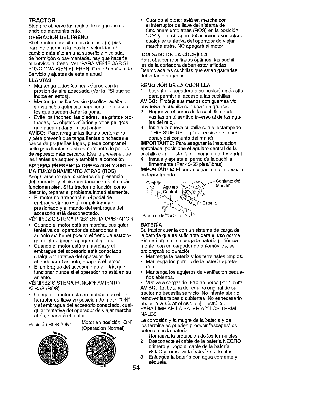
TRACTOR
Siempre observe las reglas de seguridad cu-
ando d_ mantenimiento,
OPERAOION DEL FRENO
St el tractor necesita m&s de cinco (5) pies
pare detenerse ala m_0dmavelocidad al
cambio m&s aIto en una superficie nivelada.
de hormig6n o pavimentada, hay que hacerle
el servicio al franc. Ver "PARA VERIFtCAR SI
FUNCIONA BIEN EL FRENO" en el capitulo de
Servicio y ajustes de este manual
LLANTAS
• Mantenga redes los neum&ticos con la
presiSn de aire adecuada (Ver ia PSi que se
lndica en estos)_
• Mantenga las Itantas sin gasoline, aceite o
substancias qulmicas para control de insec-
tos que pueden dafiar la goma
• Evite los tocones, las piedras, las grietas pro-
fundas, los objetos afitados y otros pe_igros
que pueden dafiar alas Ilantas,
AVISO: Para arreglar las llantas perforadas
y p6ra prevenlr que tenga Ilantas pinchadas a
cause de pequefias fugas, puede comprar el
sello pare Ilantas de su comerciante de partes
de repuesto m&s cercano. Elselto previene que
las llantas se sequen y tambi6n la corrosi6n,
SISTEMA PRESENCIA OPERADOR Y SISTE-
MA FUNCIONAMIENTO ATR_,S (ROS)
Asegurarse de que el sistema de presencia
del operador y el sistema funcionamiento atr&s
funcionen blen, Si tu tractor no funci6n come
descrito, reparar el problema inmediatamente.
• El motor no arrancar& si el pedal de
embrague/freno est& completamente
presionado y el mando del embrague del
accesorio est& desconectado:
VERIFIE_Z SISTEMA PRESENCtA OPERADOR
• Cuando el motor estA en marcha, cualquier
tentative del operador de abandoner el
asiento sin haber puesto el franc de estacio-
namiento primero, apagar& el motor,
• Cuando el motor est& en marcha y el
embrague del accesorio estA conectado.
cualquter tentative de! operador de
abandoner el asiento, apagar& el motor,
• El embrague del accesorio no tendria que
funcionar nunca si et operador no estA en su
asiento.
VE_RIFIC:ZS ISTEMA FUNCtO NAMIENTO
ATR/_S (ROS)
• Cuando e! motor est& en marcha con el in-
terrupter de Ilave en posici6n de motor "ON"
y el embrague del accesorio conectado, cual-
quiet tentative del operador de viajar marcha
atr&s, apagar& el motor°
Posici6n ROS "ON" Motor en posici6n "ON"
(Operaci6n Normal)
3_
54
Cuando el motor est& en marcha con
el interrupter de llave del sistema de
funcionamtento atr&s (ROS) en la posici6n
"ON" y el embrague del accesorio conectado,
cualquier tentative del operador de viajar
marcha atr&s, NO apagar& el motor,
CUIDADO DE LA CUCHILLA
Para obtener resultados 5ptimos, las cuchil-
las de la cortadora deben ester afiladas.
Reemplace las cuchillas qua est_n gastadas,
dobladas o dafiadasr
REMOCION DE LA CUCHILLA
1. Levante la segadora a su posici6n m&s atta
pare permitir el acceso alas cuchillas,
AViSO: Proteja sus manes con guantes y/o
envuelva la cuchilla con una tela gruesa,
2, Remueva el perno de ta cuchilla dandole
vueltas en et sentido inverse al de las agu-
jas del reloj_
3, Instale la nueva cuchilla con el estampado
'q'HIS SIDE UP" en la direccion de la sega-
dora y del conjunto del mandril,
tMPORTANTE: Pare asegurar la instalacion
apropiada, pcsicione el agujero central de Ia
cuchilla con la estrella del conjunto del mandril,
4, Instate y epriete et perno de la cuchilla
firmemente (Par 45-55 pies!libras),
IMPORTANTE: El perno especial de la cuchilla
es termotratado,
Perno de la _'t
BATERiA
Su tractor cuenta con un sistema de carga de
la bateria que es suficiente pare el use normal.
Sin embargo, si se carga la bateria periSdica-
mente, con un cargador de autom6viles, se
prolonger& su duraci6n,
• Mantenga la bateria y los terminales _impios,
• Mantenga los pemos de ia bateria apreta-
dos,
• Mantenga los agujeros de ventilaciSn peque-
5os abiertos.
• Vuelva a cargar de 6-10 amperes per 1 hera,
AVISO: La bateria del equipo original de su
tractor no becesita servicio, No intente abrir o
remover las tapes o cubiertas, No esnecesario
afiadir o verificar el nivel de,I etectrSlito.
PARA LIMPIAR LA BATERIA Y LOS TERMI-
NALES
La corrosi6n y la mugre de la bater[a y de
los terminates pueden producir "escapes" de
petencia en la bateda,
1, Remueva la protecciSn de Ios terminales.
2, Desconecte el cable de fa bateria NEGRO
primero y tuego el cable de ta bater[a
ROJO y remueva la bateria del tractor,
Enjuague la bateda con ague cordente y
s6quela,
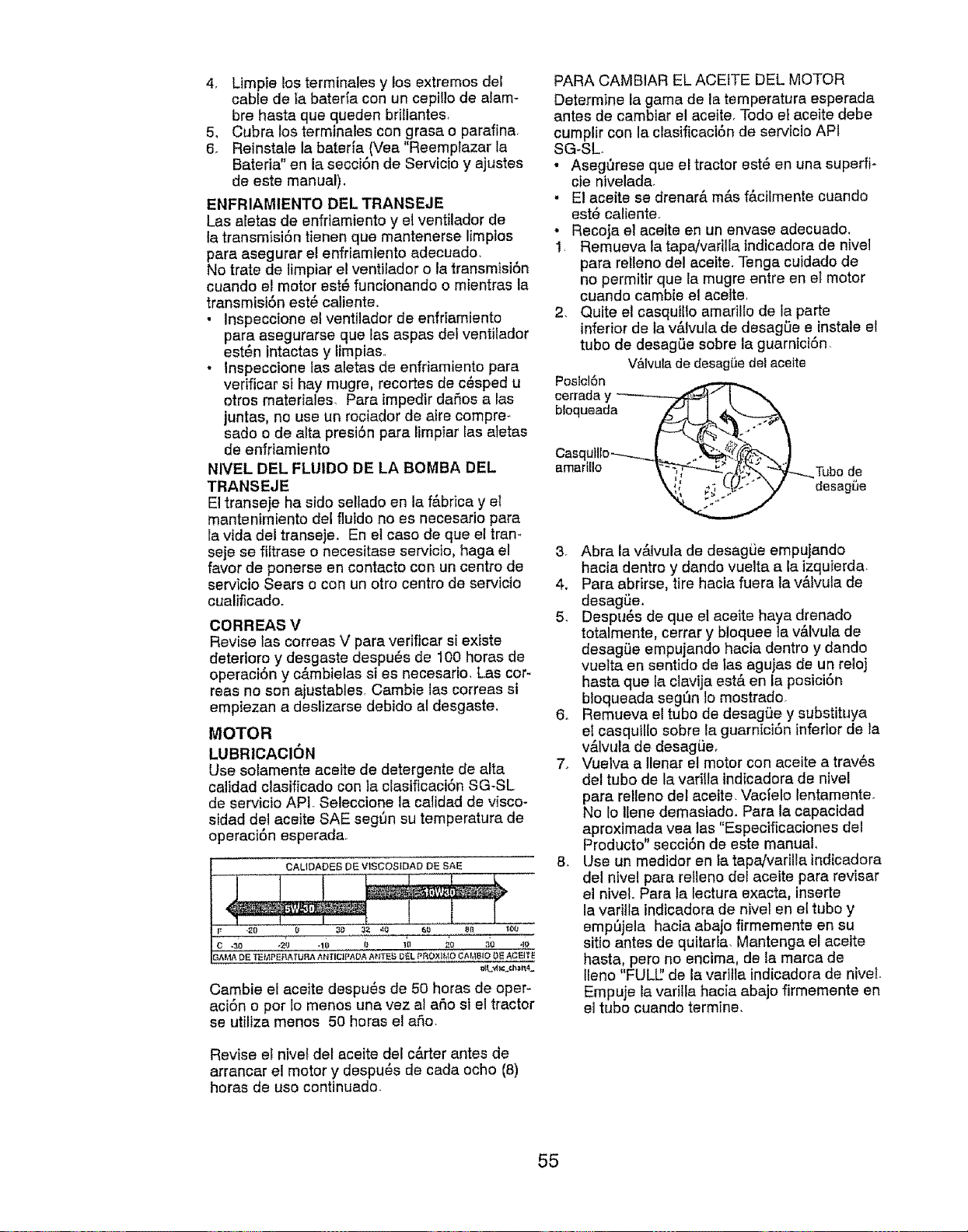
4, Limpielosterminalesy losextremosdel
cabledelabater{aconuncepitlodealam-
brehastequequedenbriilantes,
5, Cubralosterminalescongrasao parafina.
6. Reinstalelabater{a(Vea"Reemplazarla
Bateria"enlasecci6ndeServicioy ajustes
deestemanual).
ENFRIAMIENTODIELTRANSEJE
Lasaletasdeenfriamientoy elventiladorde
latransmisi6ntienenquemantenerselimpios
pareaseguraretenfriamientoedecuado.
Notratedelimpiarelventiladoro latransmisi6n
cuandoetmotorest_funcionandoo mientrasla
transmisiSnest_caliente.
• Inspeccioneelventiladordeenfdemiento
pareasegurarsequalasaspasdelventilador
est_nintactasy limpiaso
. lnspeccionelasaietasdeenfriamientopare
verificarsIhaymugre,recortesdec_spedu
otrosmateriales.ParaimpedirdaSosalas
juntas,nouseunrociadordeairecompre_
sadoodealtapresi6nparelimpiariasaletas
deenfdamiento
NIVELDELFLUIDO DE LA BOMBA DEL
TRANSEJE
El transeje ha sido sellado en la f&brica y el
mantentmiento del fluido no es necesario pare
le vide del transeje, En el caso de qua el tram
seje se filtrase o necesitase servicto, haga el
favor de ponerse en contacto con un centro de
servicto Sears o con un otto centro de servicio
cualificado.
OORREAS V
Revise las correas V para verificar si extste
detedoro y desgaste despu_s de 100 horas de
operaci6n y c_.mbielas si es necesario, Las cor-
teas no son ejustables. Cambie las correas si
empiezan a deslizarse debido al desgaste,
MOTOR
LUBRlCAClON
Use solamente aceite de detergente de alta
calidad clasificado con la clasificaci6n SG-SL
de servicio AP1. Seleccione le calidad de visco-
sided del aceite SAE segt_n su temperatura de
operaciSn esperada,
CALIDADES DE V1SCOSIDAD DE SAE
Cambie el ace]te despu_s de 50 horas de oper-
aci6n o por io menos una vez al aSo st el tractor
se utilize menos 50 horas el afio,
Revise el niveI del aceite det c&rter antes de
arrancar el motor y despu#s de cada ocho (8)
horas de uso continuado
PARA CAMBIAR EL ACEtTE DEL MOTOR
Determine la gama de la temperetura esperada
antes de cambiar el aceite, Todo el aceite debe
cumplir con la clasificaci6n de servicio API
SG-SL
• AsegQrese que el tractor est_ en una superfi-
cie nivelada.
. E! aceite se drenar& m&s f&cilmente cuando
est6 caliente,
• Recoja el acette en un envase adecuado.
1, Remueva la tapaJvarUla indicadora de nivel
para relleno del aceite. Tenga cuidado de
no permitir que la mugre entre en el motor
cuando cambie el ace]te,
2. Quite el casqutllo amarillo de la parte
inferior de la v&lvula de desagSe e instale el
tubo de desagL_e sobre la guern{ci6n.
V&lvula de desagSe del acette
Poslcl6n
cerrada y --------__._
bloqueada
Casqulllo----_.___. ._
3. Abra la v&lvula de desagiJe empujando
haole dentro y dando vuelta ala izquIerda
4, Pare abrirse, tire hacia fuera ta v&lvula de
desagi)e.
5_ Despu_s de que el eceite haya drenado
totalmente, cerrar y b!oquee la v&lvuta de
desag_e empujando hacta dentro y dando
vuelte en sentido de Ias agujes de un reloj
haste que !a clavija est& en la posicidn
bloqueada segfin 1omostrado.
6. Remueva el tubo de desagi_e y substituya
el casquil{o sobre la guarnici6n inferior de ta
v&lvula de desag_e,
7_ Vuelva a Ilenar el motor con aceite e trav6s
del tubo de la varilta indicadora de nivel
para relleno del aceite. Vac{elo lentamente.
No Io llene demasfado. Para ta capacidad
aproximeda vea tas "Especiflcaciones del
Producto" secci6n de este manual,
8. Use un medidor en la tapaivarilla indicadora
del nivel pare relleno del aceite para reviser
el nivel. Para la lecture exacte, inserte
la varilla indicadora de nivel en el tubo y
emp_jela hacia abajo firmemente en su
sitio antes de quitarla. Mentenga el aceite
haste, pero no encima, de la marca de
lleno "FULE' de la varilla indicadora de niveL
Empuje la varil{a hacia abajo firmemente en
el tubo cuando termine.
55
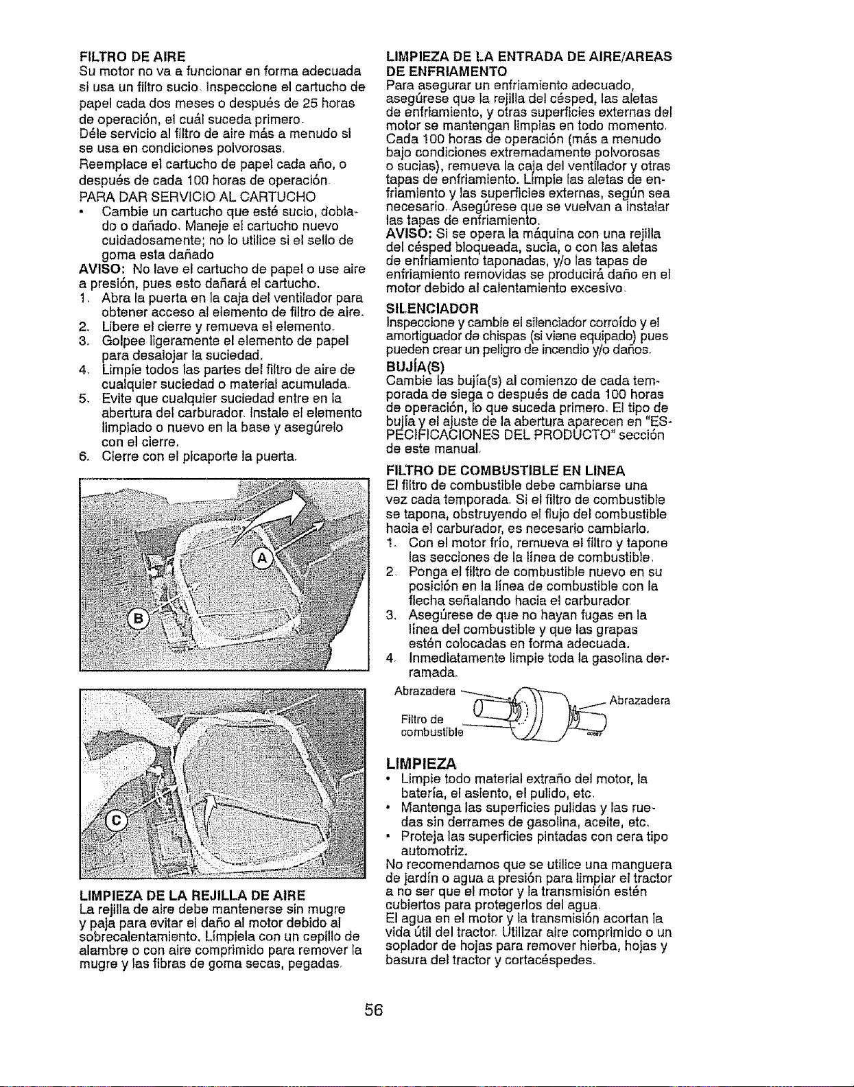
FILTRO DE AIRE
Su motor no va a functonar en forma adecuada
si usa un _tro sucio lnspeccione el cartucho de
papel cada dos meses o despu6s de 25 horas
de operaci6n, el cu&l suceda primero.
D61eservicio al fittro de aire m&s a menudo si
se usa en condiciones polvorosas.
Reemplace el cartucho de papel cada aSo, o
despu_s de cada 100 horas de operaciSn
PARA DAR SERVtCIO AL CARTUCHO
• Cambie un cartucho que est_ sucio, dobEa-
do o daSado. Maneje el cartucho nuevo
cuidadosamente; no 1outilice si el sello de
goma esta daSado
AVISO; No lave el cartucho de papel o use aire
a presi6n, pues esto daSar& el cartucho,
1. Abra la puerta en la caja del ventiiador para
obtener acceso al elemento de filtro de aire.
2. Libere e) cierre y remueva el elemento.
3o Golpee ligeramente el elemento de papel
para desalojar la suciedad,
4. Limpie todos las partes det _tro de aire de
cualquier suciedad o material acumulada.
5. Evite que cualquier suciedad entre en la
abertura del carburador, lnstale el elemento
limpiado o nuevo en la base y aseg6relo
con el cierre.
6. Cierre con el picaporte la puerta.
LIMPIEZA DE LA REJILLA DE AIRE
La rejilla de aire debe mantenerse sin mugre
y paja para evitar el dafto al motor debido al
sobrecalentamiento. Limpiela con un cepillo de
alambre o con aire comprimido para remover la
mugre y las fibras de goma secas, pegadas.
LIMPIEZA DE LA ENTRADA DE AIRE/AREAS
DE ENFRIAMENTO
Para asegurar un enfriamiento adecuado,
asegurese que la rejilia del c_sped, las afetas
de enfrtamtento, y otras superficies externas del
motor se mantengan limpias en todo memento.
Cada 100 horas de operaci6n (m&s a menudo
bajo condiciones extremadamente polvorosas
o sucias), remueva la caja del ventilador y otras
tapas de enfriamiento. Limpie las aletas de en-
friamIento y las superficies externas, seg_n sea
necesario. Asegurese que se vuelvan a instalar
las tapas de enfriamiento.
AVISO: Si se opera la m&quina con una rejiila
del c_sped bloqueada, sucia, o con las aletas
de enfriamiento taponadas, y/o las t,apas de
enfriamiento removidas se producira daSo en el
motor debido al calentamiento excesivo.
StLENCIADOR
lnspeccione y cambie el silenc]ador corroido y el
amortiguador de chispas (si viene equipado) pues
pueden crear un peligro de incendio y/o dafios.
BUJIA(S)
Cambie las bujia(s) al comienzo de cada tem-
dPoradade siega o despu_s de cada 100 horas
e operaci6n, Io que suceda primero. El tipo de
bujla y el ajuste de la abertura aparecen en "ES-
PEC_FICACIONES DEL PRODUCTO' secci6n
de este manual,
FILTRO DE COMBUSTIBLE EN LINEA
El filtro de combustible debe cambiarse una
vez cada temporada. Si el filtro de combustible
se tapona, obstruyendo el ftujo del combustible
hacia el carburador, es necesario cambtarlo.
I. Con el motor frio, remueva et filtro y tapone
las secciones de la linea de combustible,
2. Ponga el filtro de combustible nuevo en su
posici6n en la linea de combustible con la
flecha sehalando hacia el carburado_
3. AsegSrese de que no hayan fugas en la
linea del combustible y que las grapas
est6n colocadas en forma adecuada.
4. Inmediatamente limpie toda la gaso_ina der-
ramada,
Abrazadera _ _
FlEtrode "-----.-___..,] j ])u) )
combustible _kj/_
LIMPIEZA
• Limpie todo material extrafio dei motor, la
baterla, el asiento, el pulido, etc,
• Mantenga las superficies pulidas y las rue-
das sin derrames de gasolina, aceite, etc_
• Proteja las superficies pintadas con cera tipo
automotriz.
No recomendamos que se utilice una manguera
de jardin o agua a presi6n para timP,iar et tractor
a no set que el motor y la transmision esten
cubiertos para protegerlos del agua.
El agua en el motor y la transmisi6n acortan ]a
vida Qtil del tractor. Utilizar aire comprimido o un
soplador de hojas para remover hierba, hojas y
basura dei tractor y cortac_spedes.
56
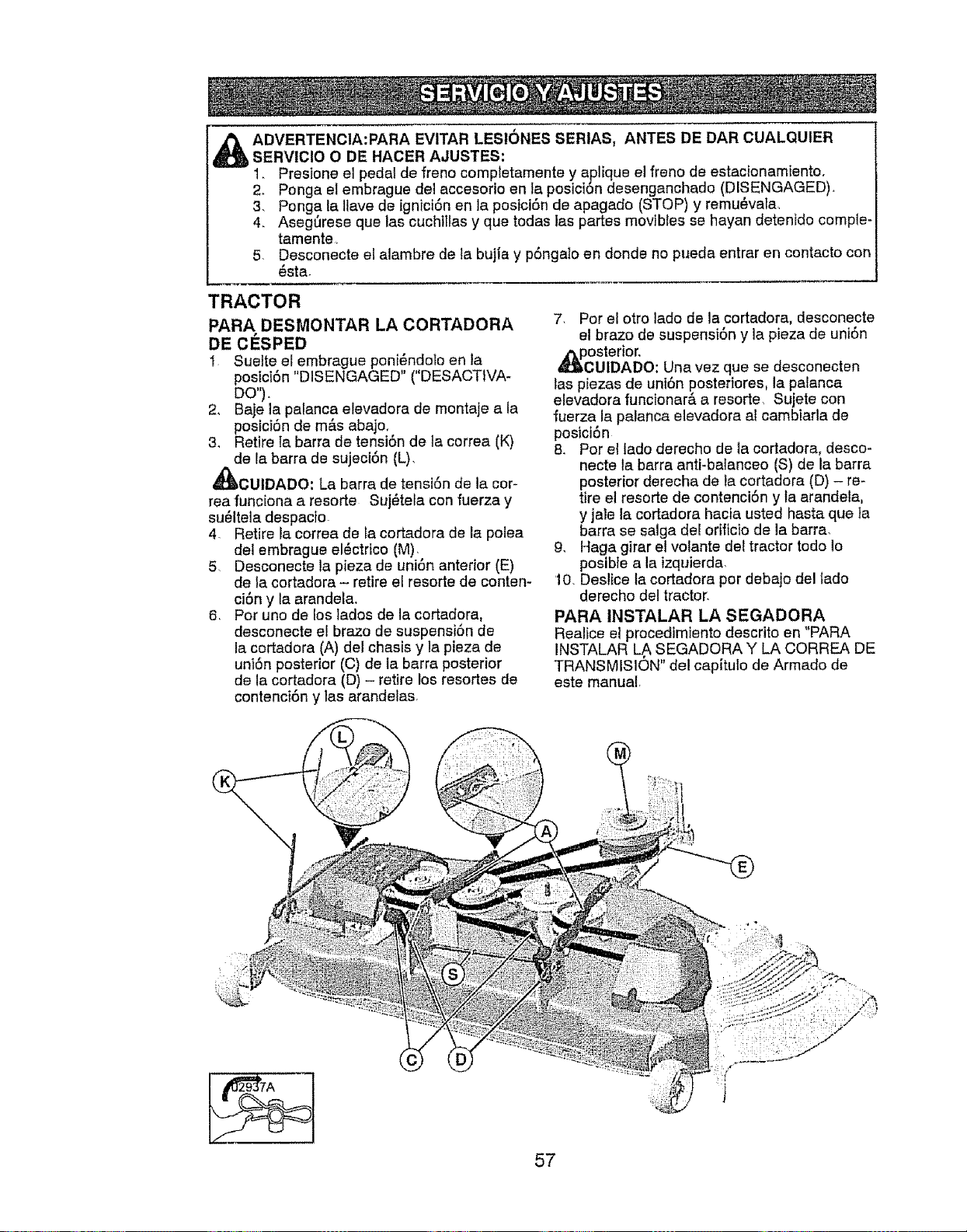
ADVERTENC1A:PARA EVITAR LES!ONES SERIAS, ANTES DE DAR CUALQUIER
SERVICIO O DE HACER AJUSTES:
1. Presione el pedal de freno comptetamente y aplique el freno de estacionamiento.
2. Ponga el embrague del accesorio en ta posici6n desenganchado (DISENGAGED),
3, Ponga la Ilave de ignici6n en la posici6n de apagado (STOP) y remu_vala
4. Aseg0rese que las cuchlllas y que todas las partes movibles se hayan detentdo comple-
tamente
5 Desconecte el alambre de la bujia y p6ngalo en donde no pueda entrar en contacto con
_sta
TRACTOR
PARA DESMONTAR LA CORTADORA
DE ClaSPED
1 Suette el embrague poni_ndoto en la
postci6n "DISENGAGED" ("DESACTIVA-
DO").
2, Baje la palanca elevadora de montaje a la
posici6n de m&s abajo,
3, Retire la barra de tensi6n de la correa (K)
de la barra de sujeci6n (L),
_CUIDADO: La barra de tensi6n de ta cor-
rea funciona a resorte Suj_tela con fuerza y
su_ltela despacto
4. Retire la correa de ta cortadora de la polea
de! embrague el6ctrico (M),
5, Desconecte la pieza de uni6n anterior (E)
de la cortadora - retire el resorte de conten-
ci6n y la arandela.
6 Por uno de los lados de la cortadora.
desconecte el brazo de suspensi6n de
la cortadora (A) del chasis y la pieza de
uni6n posterior (C) de ta barra posterior
de la cortadora (D) - retire los resortes de
contenci6n y las arandelas
7. Por el otro lado de la cortadora, desconecte
el brazo de suspensi6n y la pieza de uni6n
,_PcOSterior.
UIDADO: Una vez que se desconecten
las piezas de uni6n poeteriores, la palanca
elevadora funcionara a resorte, Sujete con
fuerza la palanca elevadora al cambiarla de
posici6n
8. Por el lado derecho de la cortadora, desco-
necte la barra anti-balanceo (S) de la barra
posterior derecha de ta cortadora (D) - re-
tire el resorte de contenci6n y ta arandela.
y jale la cortadora hacia usted hasta que }a
barra se salga del orificio de la barra.
g. Haga girar el volante de[ tractor todo Io
posible a la izquierda.
10. Deslice la cortadora por debajo de! tado
derecho del tractor,
PARA INSTALAR LA SEGADORA
Realice el procedimiento descrito en "PARA
INSTALAR LA SEGADORA Y LA CORREA DE
TRANSMLSION" del capitulo de Armado de
este manual,
57
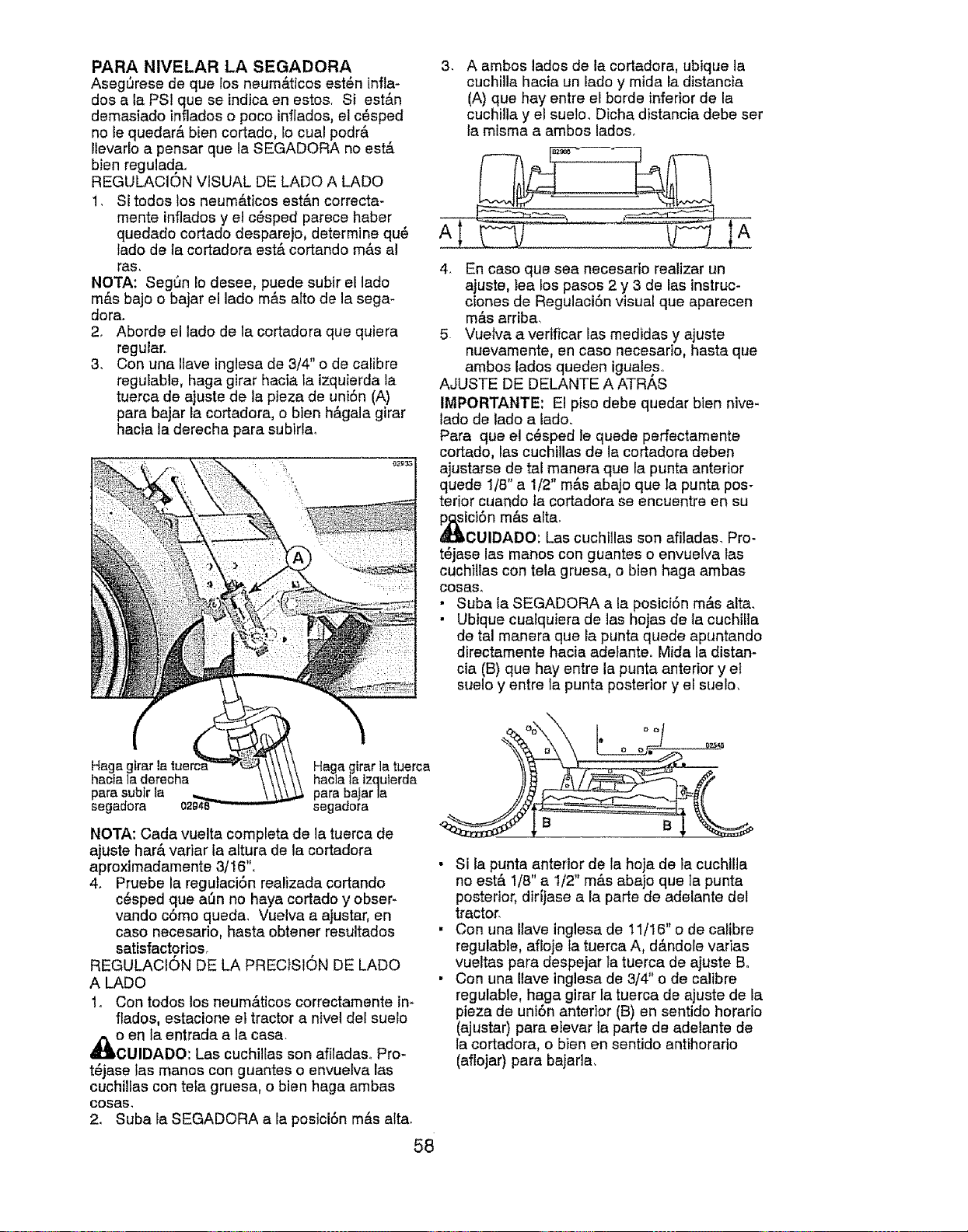
PARA NIVELAR LA SEGADORA
Asegt_rese de que los neum_.ticos est_n infla-
dos a la PSI que se indica en estos. Si est&n
demasiado inflados o poco inflados, el c_sped
no le quedar& bien cortado, Io cual podr&
Ilevarlo a pensar que la SEGADORA no est&
bien regulad,a.
REGULACION VISUAL DE LADO A LADO
1. Si todos los neurn&ticos est&n correcta-
rnente inflados y el c_sped parece haber
queclado cortado desparejo, determine qu@
lado de la cortadora est& cortando m_s al
ras.
NOTA: SegSn Io desee, puede subir el lado
m&s bajo o bajar el lado rn&s atto de la sega-
dora.
2. Aborde el lado de la cortadora qua quiera
regular.
3. Con una Ilave inglesa de 3/4" o de calibre
reguIable, haga girar hacia la izquierda ta
tuerca de ajuste de la plaza de uniSn (A)
para bajar la cortadora, o bien h&gala girar
hacia la derecha para subirla,
3,
A ambos lados de la cortadora, ubique la
cuchilla hacia un lado y mida la distancia
(A) que hay entre el borde inferior de la
cuchilla y el sueto.. Dicha distancia debe set
la rnisma a ambos lados.
4. En caso que sea necesario realizar un
ajuste, lea los pasos 2 y 3 de las instruc-
clones de Regulaci6n visual que aparecen
rn&s arriba,
5. Vueiva a verificar las rnedidas y ajuste
nuevamente, en caso necesario, hasta que
ambos lados queden iguales..
AJUSTE DE DELANTE A ATRAS
IMPORTANTE: E! piso debe quedar bien nive-
lado de lado a lado.
Para que el c@sped le quede perfectarnente
cortado, las cuchillas de la cortadora deben
ajustarse de tal manera qua la punta anterior
quede 1/8" a 1/2" rn&s abajo que la punta pos-
terior cuando la cortadora se encuentre en su
lcCi6nm&s alta.
UIDADO: Las cuchtllas son afitadas. Pro-
t_jase las manos con guantes o envuelva tas
cuchillas con tela gruesa, o bien haga ambas
cosas,
• Suba la SEGADORA a la posici6n m&s alta.
• Ubique cuafquiera de las hojas de la cuchilla
de ta! rnanera qua la punta quede apuntando
directamente hacia adelante, Mida la distan-
cia (B) que hay entre la punta anterior y el
suelo y entre la punta posterior y el suelo,
Haga glra_
hacia la derecha
para subir la
segadora
Haga girar la tuerca
hacla la tzquferda
para balar la
segadora
NOTA: Cada vuelta completa de la tuerca de
ajuste har& variar la altura de lacortadora
aproximadamente 3/16".
4. Pruebe la regutaci6n realizada cortando
c6sped que at_n no haya cortado y obser-
vando c6mo queda. Vuelva a ajustar, en
caso necesario, hasta obtener resultados
satisfactorios,
REGULACION DE LA PRECISI6N DE LADO
A LADO
1. Con todos los neum&ticos correctamente im
flados, estacione el tractor a nivel del suelo
d_o en la entrada a la casa.
CUIDADO: Las cuchillas son afiladas.. Pro-
t_jase las manos con guantes o envuelva las
cuchillas con tela gruesa, o bien haga ambas
COSaS,
2. Suba la SEGADORA a la posici6n m&s alta.
58
B B
Si ta punta anterior de la hoja de la cuchllla
no est& liB" a 1/2" m&s abajo qua la punta
posterior, dirijase a la parte de adelante det
tractor.
Con una Ilave inglesa de 11/16"o de calibre
regulable, aftoje fa tuerca A, d&ndole varias
vueltas pare, despejar Ia tuerca de ajuste B.
Con una Ilave inglesa de 3/4" o de calibre
regulable, haga glrar ta tuerca de ajuste de la
pieza de uni6n anterior (B) en sentido horatio
(ajustar) para eIevar la parte de adelante de
la cortadora, o bien en sentido antihorario
(aflojar) para bajarla,
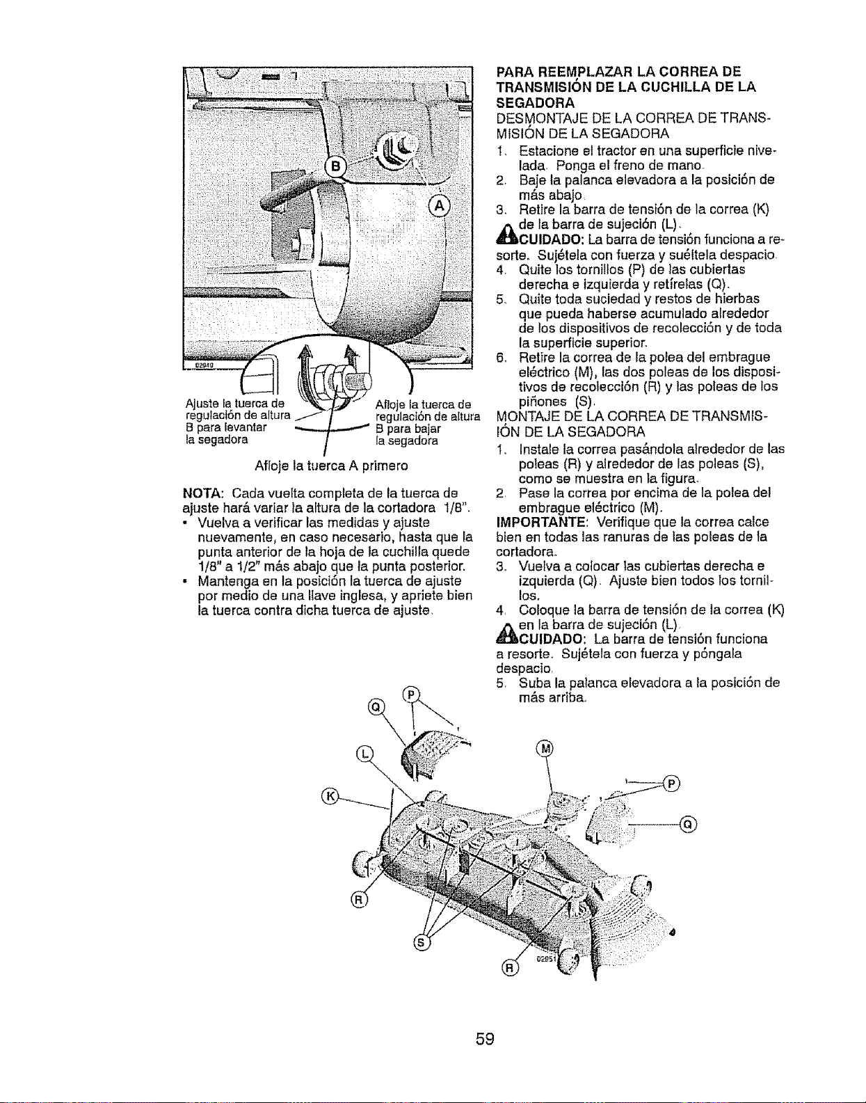
Ajuste la tuerca de
regulaciSn de altura
B para levantar
la segadora
Afloje la tuerca de
regulaot6n de altura
13para bajar
la segadora
Affoje la tuerca A primero
NOTA: Cada vuefta completa de la tuerca de
ajuste har& variar la altura de la cortadora t/8",
• Vuelva a vedficar las medidas y ajuste
nuevamente, en caso necesafio, hasta que la
punta anterior de la hoja de Ia cuchilla quede
1/8" a 1/2" m&s abajo que ta punta posterior.
• Mantenga en la posici6n la tuerca de ajuste
por medio de una Ilave inglesa, y apriete bien
la tuerca contra dicha tuerca de ajuste,
PARA REEMPLAZAR LA CORREA DE
TRANSMISION DE LA CUCHILLA DE LA
SEGADORA
DESMONTAJE DE LA CORREA DE TRANS-
MfSION DE LA SEGADORA
1. Estacione el tractor en una superficte nive-
lada, Ponga el freno de mano.
2. Baje la palanca elevadora a la posici6n de
m_s abajo
3. Retire la barra de tensi6n de la correa (K)
_lbde la barra de sujeci6n (L),
CUIDADO: La barra de tensi6n funciona a re-
sorte, Suj_tela con fuerza y su@ltela despacio,
4, Quite los tornillos (P) de las cubiertas
derecha e izquierda y ret_relas (Q).
5_ Quite toda suciedad y restos de hierbas
que pueda haberse acumulado alrededor
de los dispositivos de recolecci6n y de toda
la superficie superior.
6. Retfre la correa de la porea del embrague
el@ctrico (M), las dos poleas de los disposi-
tivos de recolecci6n (R) y tas poleas de los
piSones (S).
MONTAJE DE LA CORREA DE TRANSMrS-
r6N DE LA SEGADORA
I, Instale la correa pas&ndola alrededor de las
poleas (R) y airededor de las poleas (S),
como se muestra en ia figura,
2 Pase la correa pot encima de la polea del
embrague el6ctrico (M),
IMPORTANTE: Verifique qua la correa calce
blen en todas las ranuras de las poleas de ta
cortadorao
3. Vuelva a colocar las cubiertas derecha e
izquierda (Q), Ajuste bien todos los tornil-
los.
4, CoEoque la barra de tensi6n de la correa (K)
,_en fa barra de sujeci6n (L),
CUIDADO: La barra de tensi6n funciona
a resorter Suj_tela con fuerza y p6ngala
despacio,
5, Suba la patanca eEevadora a la posici6n de
m&s arriba,
59
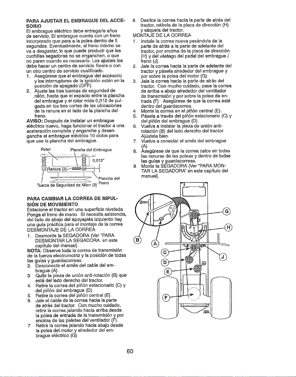
PARA AJUSTAR EL EMBRAGUE DEL ACCE-
SORIO
El embrague el_ctrico debe entregarle afios
de servicio. El embrague cuenta con un franc
incorporado qua para ala polea dentro de 5
segundos. Eventualmente, el freno interno se
va a desgastar, Io que puede producir que las
cuchillas segadoras no se enganchen, o qua
no paren cuando es necesafio. Los ajustes los
debe hater un centro de servicio Sears o con
un otro centro de servicio cualificedo,
1. Asegl3rese que e! embrague del accesorio
y los interruptores de la tgnici6n est_n en la
posici6n de apagado (OFF).
2. Ajuste lee tres tuercas de seguridad de
nil6n, haste que el espacio entre la ptancha
del embrague y el rotor mida 0,012 de pul-
gada en los tres cortes de las ubicaciones
de la ranura en el lado de la plancha del
freno,
AVISO: Despu6s de instalar un embrague
el6ctrico nuevo, hage funcionar el tractor a una
aceleraci6n complete y enganche y desen-
ganche el embrague et6ctrico 10 ciclos para
que use la plancha del embrague.
Rotor Planchadel Embrague
' __ .........\ _1' 0,021"
,/ _._------------;:2- Pfanchadel
/ Freno
Tuercade Seguridadde Nlion (3)
PARA CAMBIAR LA CORREA DE IMPUL-
SION DE MOVIM|ENTO
Estacione el tractor en una superficie nivelade,
Ponga el freno de meno. Si necesita asistencia,
del lado de abajo del apoyapi6s izquierdo hey
una gula practice pare el montaje de Ia correa
DESMONTAJE DE LA CORREA
I. Desmonte ta SEGADORA (Ver"PARA
DESMONTAR LA SEGADORA en este
cap[tulo del manuat).
NOTA: Observe toda fa correa de transmtsi6n
de la fuerza etectromotriz y la posici6n de todas
las gules y guardacorreas,
2. Desconecte el arn6e del cable del em-
brague (A).
3. Quite la pieza de uni6n anti-rotaci6n (B) qua
est& de1 lado derecho del tractor.
4. Retire la correa del pi56n estacionario (C) y
del pifiSn del embrague (D).
5. Retire le correa del pi56n central (E).
6. Jale el cable de la correa hacia la parte
de atr&s del tractor. Con mucho cuidado,
retire la corree jalando hacia arriba desde
la polea de entrada de la transmisi6n y por
encima de tas paletas del ventilador (F).
7. Retire la correaialando hacia abajo deede
la polea del motor y alrededor del em-
brague el_ctrico (G),
8 Deslice la correa hacia ]a parte de atr&s del
tractor, retirela de fa place de direcci6n (H)
y s&quela del tractor,
MONTAJE DE LA CORREA
1_ instele fa correa nueva pas_.ndola de la
parte de atr&s ale parte de adelante del
tractor, por encima de la place de direcci6n
(H) y del v&stago del pedal del embrague /
franc (J).
2. Jale la correa hacia la parte de adelante det
tractor y p&sela alrededor del embrague y
pot sobre la polea del motor (G).
3_ Jale la correa hacie fa parte de atr&s det
tractor. Con mucho cuidado, pase la corree
de ardba a abajo alrededor del ventilador
de transmisi6n y por sobre la polea de en-
trade (F), Asegl]rese de que le correa est6
dentro del guardacorrea,
4. Monte la correa en el pi55n central (E).
5o P&seta a trav6s det pifi6n estacionario (C) y
del pi_i6n del embrague (D).
6. Vuelva a instalar le pieza de uniSn anti-
rotaciSn (B) del lado derecho del tractor.
AjSstela bien.
7 Vuelva a conectar el arn_s del embrague
(A).
8. Asegl]rese de qua la correa calce en todas
las ranuras de fas poleas y dentro de todas
las gules y guardacorreaso
9. Monte la SEGADORA (Ver"PARA MON-
TAR LA SEGADORA" en este capituto del
manual).
6O
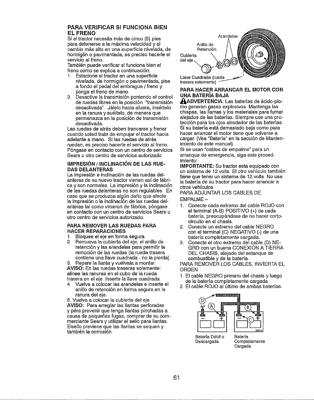
PARA VERtFICAR Sl FUNCIONA BIEN
EL FRENO
Si el tractor necesita m&s de cinco (5) pies
para detenerse a la m_xima velocidad y al
cambio m,_s alto en una superficie nivefada, de
hormig6n o pavimentada, es preciso hacerle e!
servicio al freno.
Tambi_n puede verificar si funciona bien e!
freno como se explica a continuaci6n:
1, Estacione el tractor en una superficie
nivelada, de hormig6n o pavimentada, pise
a rondo e{ pedal det embrague / freno y
ponga el freno de mano.
2. Desactive la transmisi6n poniendo e! control
de ruedas Iibres en la posici6n "transmtsi6n
desactivada'. J&lelo hacia afuera, ins_rtelo
en la ranura y su6ltelo0 de manera que
permanezca en la posici6n de transmisi6n
desactivada.
Las ruedas de atr&s deben trancarse y frenar
cuando usted trate de empujar el tractor hacia
adelante a mano. Si las ruedas de atr&s
ruedan, es preciso hacerle et servicio al freno,
P6ngase en contacto con un centro de servicios
Sears u otro centro de servicios autorizado.
IMPRESION / INCLtNACl6N DE LAS RUE-
DAS DELANTERAS
La impresi6n e inclinaci6n de las ruedas del-
anteras de su nuevo tractor vienen asi de f&brt-
ca y son normales, La impresi6n y la inclinaci6n
de las ruedas delanteras no son regulables, En
case que se produzca algSn daSo que afecte
Faimpresi6n o la inclinaci6n de las ruedas del-
anteras tal como vinleron de f&brica, p6ngase
en contacto con un centro de servicios Sears u
otto centro de servicios autorizado_
PARA REMOVER LAS RUEDAS PARA
HACER REPARACIONES
1 Bloquee el eje en forma segurar
2 Remueva la cubierta del eje, el anillo de
retenci6n y las arandelas para permitir la
remoci6n de las ruedas (la rueda trasera
contiene una ltave cuadrada - no la pierda),
3, Repare la Ilanta y vu_lvala a montar,
AVISO: En las ruedas traseras solamente',
alinee las ranuras en el cubo de la rueda
trasera en el eje Inserte la Ilave cuadrada.
4. Vuelva a colocar las arandelas e inserte el
anillo de retenci6n en forma segura en la
ranura del eje.
5, Vuelva a colocar la cubierta del eje_
AVISO: Para arregtar las Ilantas perforadas
y p_ra prevenir que tenga itantas pinchadas a
causa de pequeSas fugas, comprar de su com-
merciante Sears y utilizar et sello para Itantas,
Elsello previene que las llantas se sequen y
tambi_,n la corrosi6n
Anlllo de
Retenci6n
Cub[erta
del '
Arandetas
I
Llave Cuadrada(rueda.__
traserasolamente)
PARA HACER ARRANOAR EL MOTOR CON
UNA BATERiA BAJA
_I_ADVERTENCIA: Las baterEas de &cido-plo*
mo generan gases explosivos, Mantenga las
chispas, las llamas y los materiales para fumar
atejados de las baterfas, Siempre use una pro-
tecci6n para los ojos alrededor de las baterias.
Si su bater[a est& demasiado baja como para
hacer arrancar el motor tiene que volverse a
cargar. (Vea "Baterla" en la secci6n de Manten-
imiento de este manual)
St se usan "cables de empalme" para un
arranque de emergencia, siga este proced-
lmtento;
IMPORTANTE: Su tractor esta equipado con
un sistema de 12 volts. El otro veh_culo tambi_n
tiene que tener un sistema de 12 volts, No use
fa baterla de su tractor para hacer arrancar a
otros veh[culos.
PARA ADJUNTAR LOS CABLES DE
EMPALME -
1. Conecte cada extreme del cable ROJO con
el terminal (A-B) POS1TIVO (+) de cada
bateria, preocup&ndose de no hacer corto-
circuito en el chasis,
2. Conecte un extremo del cable NEGRO
con el terminal (C) NEGATIVO (-) de una
bateria completamente cargada,
3. Conecte el otto extremo del cable (D) NE-
GRO con un buena CONEXION A TIERRA
DEL CHASIS, alejado de] estanque de
combustible y de la baterfa,
PARA REMOVER LOS CABLES, tNVIERTA EL
ORDEN
1, El cable NEGRO primero del chasis y luego
de [a bateda completamente cargada,
2, El cable ROJO al _ltimo de ambas baterias.
Bateria D_bfl o Bateria
Descargada Completamente
Cargada
61
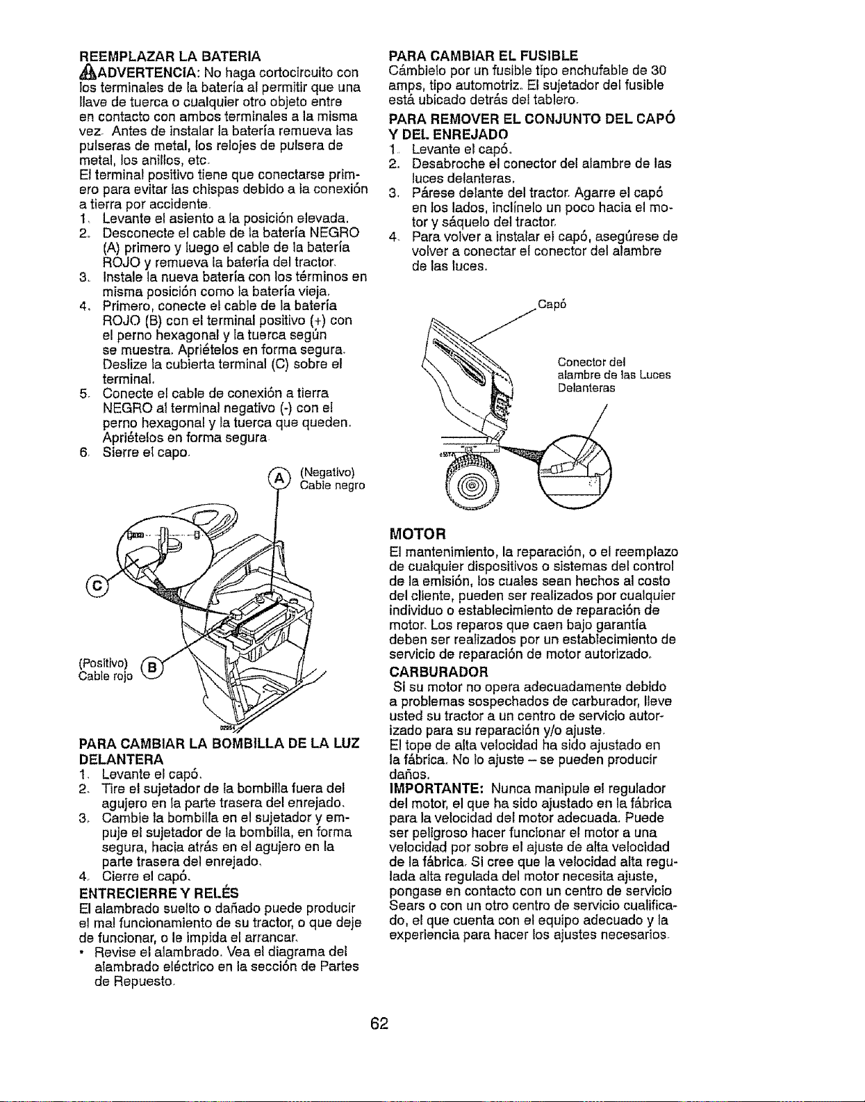
REEMPLAZAR LA BATERIA
,_J_,ADVERTENCIA: No haga cortocircuito con
los terminales de la baterla al permitir que tJna
tlave de tuerca o cualquier otro objeto entre
en contacto con ambos terminales ala misma
vez Antes de instalar la bateria remueva los
pulseras de metal, los reloies de pulsera de
metal, los anillos, etc.
El terminal positivo tiene qua conectarse prim-
ero pare evitar tas chispas debido a fa conexiOn
a tierra pot accidente.
1. Levante el asiento a Ia posici6n elevada,
2o Desconecte el cable de la baterfa NEGRO
(A) primero y Iuego el cable de la bateria
ROJO y remueva la bateria del tractor.
3. Instale la nueva batefia con los t_rminos en
misma posiciOn como la bateria vieja.
4_ Primero, conecte el cable de la bateria
ROJO (B) con el terminal positivo (+) con
el perno hexagonal y Ia tuerca segOn
se muestra. Apri6telos en forma segura.
Desiize ta cubierta terminal (C) sobre el
terminal,
5. Conecte el cable de conexiOn a tierra
NEGRO a} terminal negativo (-) con el
perno hexagonal y la tuerca que queden.
Apri_telos en forma segura
6 Sierra etcapo.
(_ (Negattvo)
Cable negro
(Pos|tfvo)
Cable rojo
PARA CAMBIAR LA BOMB1LLA DE LA LUZ
DELANTERA
1_ Levante el capS.
2. Tire el sujetador de la bombiHa fuera del
agujero en la porte trasera del enrejado.
3o Cambie la bombiita en el sujetador y em-
puje el sujetador de ta bombilla, en forma
segura, hecia atr&s en el agujero en la
porte trasera del enrejado,
4. Cierre el cap0,
ENTRECIERRE Y RELI_S
El alambrado suetto o daSado puede producir
el mal funcionamiento de su tractor, o que deje
de funcionar, o le imptda el arrancar.
• Revise el alambrado, Vea el diagrama del
alambrado el_ctrico en la secciOn de Partes
de Repuesto.
PARA CAMBIAR EL FUSIBLE
C&mbielo por un fusible tipo enchufable de 30
amps, tipo automotriz.. El sujetador del fusible
estA ubicado detr&s del tablero.
PARA REMOVER EL CONJUNTO DEL CAPO
Y DE[. ENREJADO
1. Levante el cap0.
2. Desabroche el conector del alambre de los
luces delanteras,
3. P_.rese delante del tractor. Agarre el cap0
en los lados, incl{nelo un poco hacia el mo-
tor y sAquelo del tractor,
4. Pare volver a instalar el cap0, asegt'_rese de
volver a conectar et conector del alambre
de los luces.
Conector del
alambre de las Luces
Delanteras
MOTOR
El mantenimiento, la reparaci6n, o el reemptazo
de cualquier dispositivoso sistemas del control
de la emisi6n, los cuales seen hechos al costo
del cliente, pueden ser realizados por cualquier
individuoo establecimiento de reparaci6n de
motor. Los reparos qua caen bajo garantfa
deben ser realizados por un estabtecimiento de
servicie de reparaci6n de motor autorizado_
CARBURADOR
Sl su motor no opera adecuadamente debido
a problemas sospechados de carburador, Ileve
usted su tractor a un centro de servicfo autor-
izado pare su reparaci6n y/o ajuste.
El tope de alto velocidad ha sido ajustado en
ta f&bricao No Io ajuste - se pueden producir
daSos,
IMPORTANTE: Nunca manipule el regulador
de! motor, el que ha stdo aiustado en la f_.brica
pare la velocidad del motor adecuada. Puede
ser peligroso hacer functonar el motor a una
velocidad por sobre el ajuste de alto velocidad
de la f&brica. St cree que la velocidad alto regu-
tada alto regulada del motor necesita ajuste,
pongase en contacto con un centro de serviclo
Sears o con un otro centro de servicio cuatifica-
do, el qua cuenta con et equipo adecuado y la
experiencia pare hacer los ajustes necesarios.
62
Inmediatamente prepare su tractor pare el
elmecenamiento al final de la temporada o si el
tractor no se va a usar per 30 dies o re&s+
_kADVERTENGIA: Nunca almacene el trac-
tor con gasoline en el estanque dentro de un
edificio en deride los gases pueden alcanzar
una llama expuesta o una chispa, Permita qua
el motor se enfrie antes de almacenarlo en
cualquier recinto privado.
TRACTOR
Cuando el tractor se ve e almecenar per cierto
periodo de tiempo, limpiela cuidadosamente,
quite teda la mugre, la grasa, las hojas, etc.
Gu&rdete en una _,ree limpia y seca,
1, Llmpie todo el tractor (vea "LIMPIEZ/_' en la
secci6n de Mantenimiente en este manual).
2. tnspeccione y cambie las correas, si es
necesario (vee las instrucetonespare el
cambio de las correas en la secci6n de
Servicio y Ajustes de este manual).
3, Lubr[quelo, segt3n se muestra en la secci6n
de Mantenimiento de este manual.
4, Asegt_rese que todas las tuercas, los
pernos y los tornitlos est6n sujetados
en forma segura Inspeccione las partes
movibles para verificar si hay daSo, rotura o
desgaste+ C&mbielas si es necesario.
5. Retoque todas superficies pintadas oxide-
des o picadas; aplique lija antes de pintar.
BATERiA
• Cargue la baterfa completamente antes de
guardarla+
• Despu6s de cierto periodo de tiempo en
almacenamiento, la bateria puede necesiter
volver a cargarse.
, Pare ayudar a evitar la corrosi6n y las fugas
de petencia durante largos periedos de
atmacenamiente, se deben desconectar
los cables de la bateria y se debe limpiar
cuidadesamente (vea "PARA LIMPIAR LA
BATERiA Y LOS TERMINALES" en le sac+
ci6n de Mantenimientode este manual)+
• Despu6s de limpiarla, deje los cables desco-
nectados y p6ngatos en donde no puedan
entrar en contacto con los terminales de la
bateria+
• Si se remueve la baterla del tractor pare el
almacenamlento, no la guarde directamente
sobre concrete o sobre superficies h'3medas_
MOTOR
SISTEMA DE COMBUSTIBLE
IMPORTANTE: Es important evitar qua se
forman depositos de goma en pertes funde-
mentales del sistema de cembus+tible tales
come et carburador, el filtro del combustible,
la manguera del combustibles mezclados con
alcohol (conecido come gasohol o que t+enen
etanol o materiel) pueden etraer humedad, to
ue conduce ala separaci6n y ale formaci6n
e ecudos durante elalmacenamiento. Le
gasolina acidica puede daSer el sistema de
combustible de un motor durante el periodo de
almacenamiento+
• Vaciar el dep6site del carburante poniende
en marcha el motor y dej_ndolo funcioner
haste que el carburante termine et carbura-
dot est_ vacio.
• Nunca use los productos pare limpieza det
carburador o del motor en el estanque de
combustible pues se pueden producir daSos
permenentes+
• Use combustible nuevo la pr6xima
temporada+
AVISO: El estab[lizador de combustible es una
alternativ.a aceptable pare reducir a un minima
le formacion de depositos de goma en el com.+
bustible durante el per_odo de almacenamiento+
Agregue estabilizador ala gasoline en el
estanque de combustible o en el envase para el
almacenamiento. Siempre siga la proporci6n de
mezcla que se encuentra en el envase del esta-
bilizador, Haga funcionar el motor per Io manes
10 minutes despu_s de
o agregar el estabilizador,
para permitir que este Ilegue al carburador. No
vaciar la gasoline del estanque de gasoline yet
carburador si se est& usando estabilizador de
combustible.
ACEITE DEL MOTOR
Drene el aceite (con el motor caliente) y
c&mbielo con aceite de motor limpie. (Vea "MO-
TOR" en la secci6n de Mantenimiento" de este
manual.)
ClLINDRO(S)
1, Remuevala(s) bujia(s).
2+ Vacie una onza de aceite a trav6s def
agujero(s} de le bujla en el cilindro(s),
3. Gire la Ilave de ignici6n ala posici6n de 'Ar-
ranque" (Start), per unos cuantos segundos
pare distribuir el aceite+
4+ Cambie per bujia(s) nueva(s)
OTROS
• No guarde le gasoline de una temporada ala
otra,
• Camble el envase de la gasolina si se emp+
ieza a oxidar, Le exidaci6n y/o la mugre en
su gasoline produeir&n problemas+
• Si es posible, guarde su unidad en un recinte
cerrado y c_brala pare protegerla contra el
polvo y la mugre.
. Cubra su unidad con un forro protector
adecuado qua no retenga Ia humedad No
use pl&stico+ El pl&stico no puede respirar, lo
qua permite la formaci6n de condensaci6n,
Io que productr& {a oxideci6n de su unidad,
IMPORTANTE: Nunca cubra et tractor mientras
el motor y les areas de escape tedavia estan
calientes
63
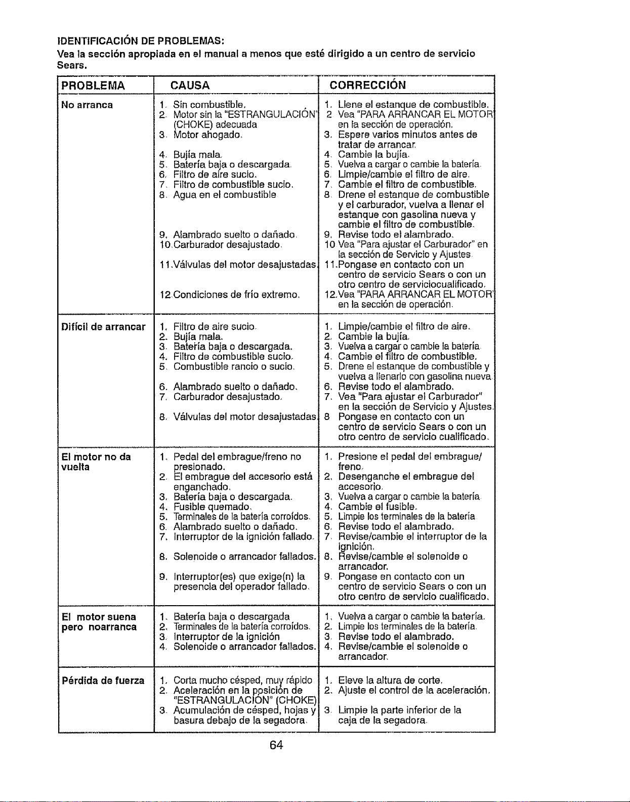
1DENTIFICACION DE PROBLEMAS:
Vea la secci6n apropiada en el manual a menos qua est_ dirigldo a un centro de servicio
Sears.
CAUSA CORRECCIONPROBLEMA
No arranca
Dificil de arrancar
El motor no da
vuelta
El motor suena
_ero noarranca
P_rdtda de fuerza
t. Sin combustible.
2. Motor sin la "ESTRANGULACI(DN'
(CHOKE) adecuada
3. Motor ahogado.
4. Bujia mala.
. Baterla baja o descargada
6. Filtro de aire sucio.
7. Filtro de combustible sucio.
8. Agua en el combustible
g. Alambrado suelto o daSado.
I O.Carburador desajustado.
11.V_.lvulas del motor desajustadas.
12Condiciones de frio extremo.
1. Fittro de aire sucio.
. Bujla mala.
. Bateria baja o descargada.
4. Filtro de combustible sucio.
5. Combustible rancio o sucio.
6_ Alambrado suelto o dar_ado.
7. Carburador desajustado.
8. V&lvulas del motor desajustadas
1. Pedal del embrague/freno no
presionado.
2. El embrague del accesorio esta
enganchado.
3. Bateria baja o descargada.
4. Fusible quemado.
5. Terminalesde la bateria corrofdos.
6. Alambrado suelto o dadado.
7. lnterruptor de la ignict6nfalladoo
8. Solenoide o arrancador falladoso
9.
Interruptor(es) que exige(n) la
presencia del operador fallado.
1. Bateria baja o descargada
2. Terminalesde la bateda corroidos
3. ]nterruptor de la ignici6n
4. Solenoide o arrancador failados.
1. Corta mucho c6sped, muy r_pido
2. Aceleracion en la ppsicion de
"ESTRANGULAC!ON"(CHOKE)
3. AcumulaciSn de c6sped, hojas y
basura debajo de la segadora.
1. Llene el estanque de combustible.
2 Vea "PARA ARRANCAR EL MOTOR
en fa secci6n de operaci6n.
3o Espere varios minutos antes de
tratar de arrancar.
4. Cambie la bujia.
5. Vuelva a cargar o cambie la bateria.
6. Limpieicambie el fittro de atre.
7. Cambie el filtro de combustible.
8. Drene e! estanque de combustible
y el carburador, vuelva a Ilenar el
estanque con gasolina nueva y
cambie el filtro de combustible.
9. Revise todo el alambrado.
10 Vea "Para ajustar el Carburador" en
la secciSn de Servicio y Ajustes.
11.Pongase en contacto con un
centro de servicio Sears o con un
otro centro de serviciocualificado.
12°Vea "PARA ARRANCAR EL MOTOR
en la secci6n de operaci6n.
1. Limpie/cambie el filtro de aire.
2. Cambie la bujia.
3. Vue[va a cargar o cambie la bateria
4. Cambie el filtro de combustible.
5. Drone et estanque de combustible y
vuelva a llenarlo con gasolina nueva
6. Revise todo el alambrado.
7. Vea "Para ajustar el Carburador"
en la seccion de Servicio y Ajustes
8 Pongase en contacto con un
centro de servicio Sears o con un
otro centro de servicio cualificado.
1. Presione el pedal det embrague/
freno.
2. Desenganche el embrague del
accesorio.
3. Vuelva a cargar o cambie la bateria
4. Cambie el fusible.
5. Limpie los 1erminalesde la bateria
6. Revise todo el alambradoo
7. Revise/cambie el interruptor de la
ignici6n.
8. Revise/cambie et solenoide o
arrancadoro
9. Pongase en contacto con un
centro de servicio Sears o con un
otro centro de servlcio cua]ificado.
1. Vuelva a cargar o cambie la bateria.
2. Limpia los terminales de la bateria.
3. Revise todo el alambrado.
4. Revise/cambie el solenoide o
arrancador.
1o Eleve la altura de corte.
2. Ajuste el control de la aceteraci6no
3_
Limpie la parte inferior de ta
caja de la segadora.
64
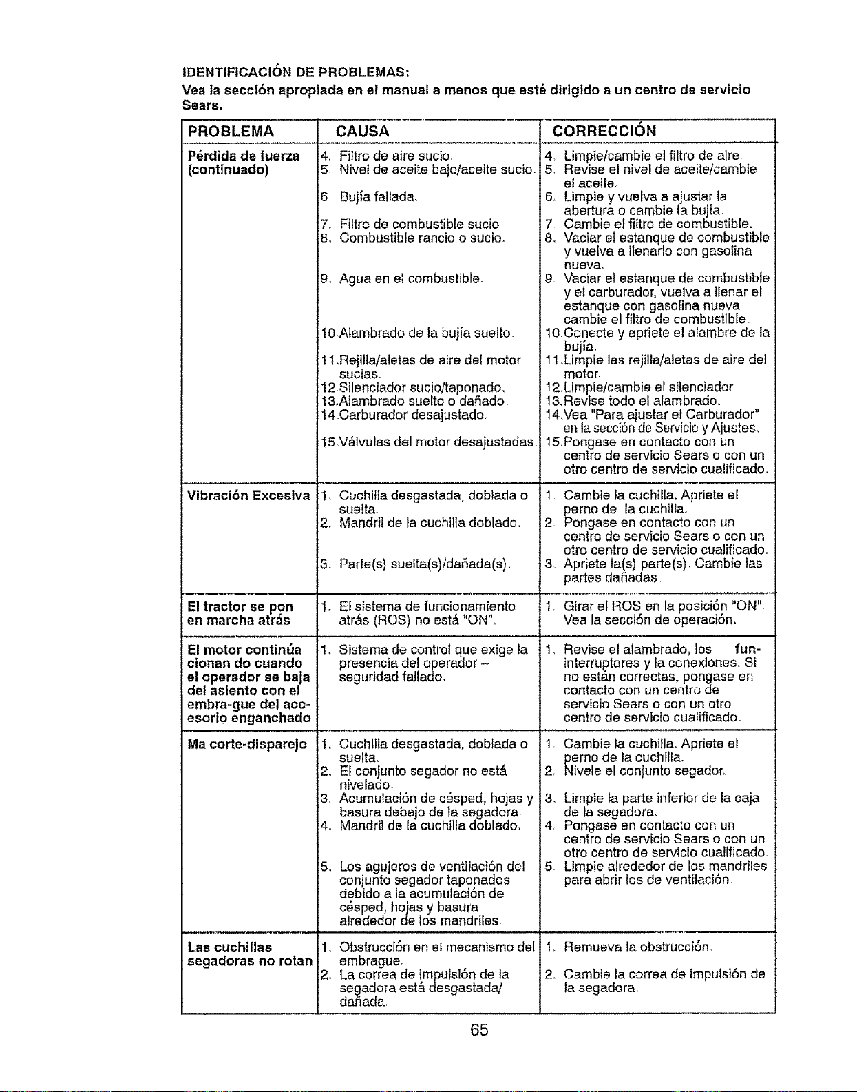
IDENTIFiCACION DE PROBLEMAS:
Vea ta secci6n aproplada en el manual a menos que est6
Sears,
PROBLEMA CAUSA i
P_rdida de fuerza
(continuado)
Vibraci6n Exceslva
El tractor se pon
en marcha atras
El motor continda
cionan do cuando
el operador se baja
del asiento con el
embra-gue del acc-
esorio enganchado
4, Firtro de aire sucio_
5 Nivel de aceite bajo/acelte sucio.
6. Bujfa fatlada,
7_ Filtro de combustible sucio
8. Combustible rancio o sucio.
9, Agua en el combustible.
10,Atambrado de ta bujia suelto.
11Rejilla/aletas de aire del motor
sucias.
12.Silenciador sucio/taponado,
l&Alambrado suelto o dafiado.
14Carburador desajustado.
15,V&lvulas del motor desajustadas,
,
3.
1.
1.
Cuchilla desgastada, doblada o
suelt&
Mandril de ta cuchilIa doblado.
Parte(s) suelta(s)/dal_ada(s),
dirigido a un centro de servicio
CORRECClON
4, Limpie/cambie el flit de aire
5. Revise el nivel de aceite/cambte
el aceite,
& Limpie y vuelva a a ustar la
abertura o cambie la buj[a.
7. Cambie e_fittro de combustible.
8, Vaciar el estanque de combustible
y vuelva a Ilenado con gasolina
nueva_
9 Vaciar el estanque de combustible
y el carburador, vue Ilenar el
estanque con gasolina nueva
cambie el filtro de c_ ,bustibEe.
10.Conecte y apriete el alambre de la
bujia,
11.Limpie las rejilta/aletas de aire del
motor
12.Limpie/cambie el silenciador
13,Revise todo el alam do.
14.Vea "Para ajustar el Carburador"
en la secci6n de Servi y Ajustes,
15.Pongase en contacto con un
centre de servicio Sears o con un
otto centre de servk *o cualificado,
1 Cambie la cuchilla., ,priete el
perno de la cuchi!la
2 Pongase en contact un
centre de servicio Sears o con un
otto centre de servicio cualificado.
3 Apriete la(s) parte(s Cambie las
partes daSadas_
Ef sistema de funcionamiento 1, Girar el ROSen la posici6n "ON"
atrAs (ROS) no est& "ON",, Vea la secciSn de el_eraci6n,
Sistema de control que exige la 1, Revise el alambrad(_, los fun-
presencia del operador - interruptores y la co 'ones. Si
seguridad fatlado, no estan correctas, pongase en
Ma corte-dispare]o 1, Cuchilla desgastada, dob]ada o
suelta.
2. El conjunto segador no est&
nivelado.
3, AcumulaciSn de c6sped, hojas y
basura debajo de la segadora
4. Mandril de la cuchilta doblado,
Los agujeros de ventilaci6n del
conjunto segador taponados
debido a la acumulaciSn de
c#sped, hojas y basura
alrededor de los mandriles,
5_
Las cuchillas
segadoras no rotan
1, Obstrucci6n en el mecanismo del
embrague.
2. La correa de impulsi6n de la
segadora est& desgastada/
dahada,
contacto con un cer de
servicio Sears o cor un otro
centre de servicio cualificado.
1 Cambie la cuchilla., ,priete e!
perno de la cuchitla,
2, Nivele el conjunto s, sdor,
3. Limpie la parte infer de la caja
de la segadora.
4 Pongase en contact con un
centre de servicio Sears o con un
otro centre de servi(' cualificado.
5. Limpie alrededor de mandriles
para abrir los de vet "
1, Remueva la obstruc
2. Cambie la correa de impulsi6n de
la segadora.
65
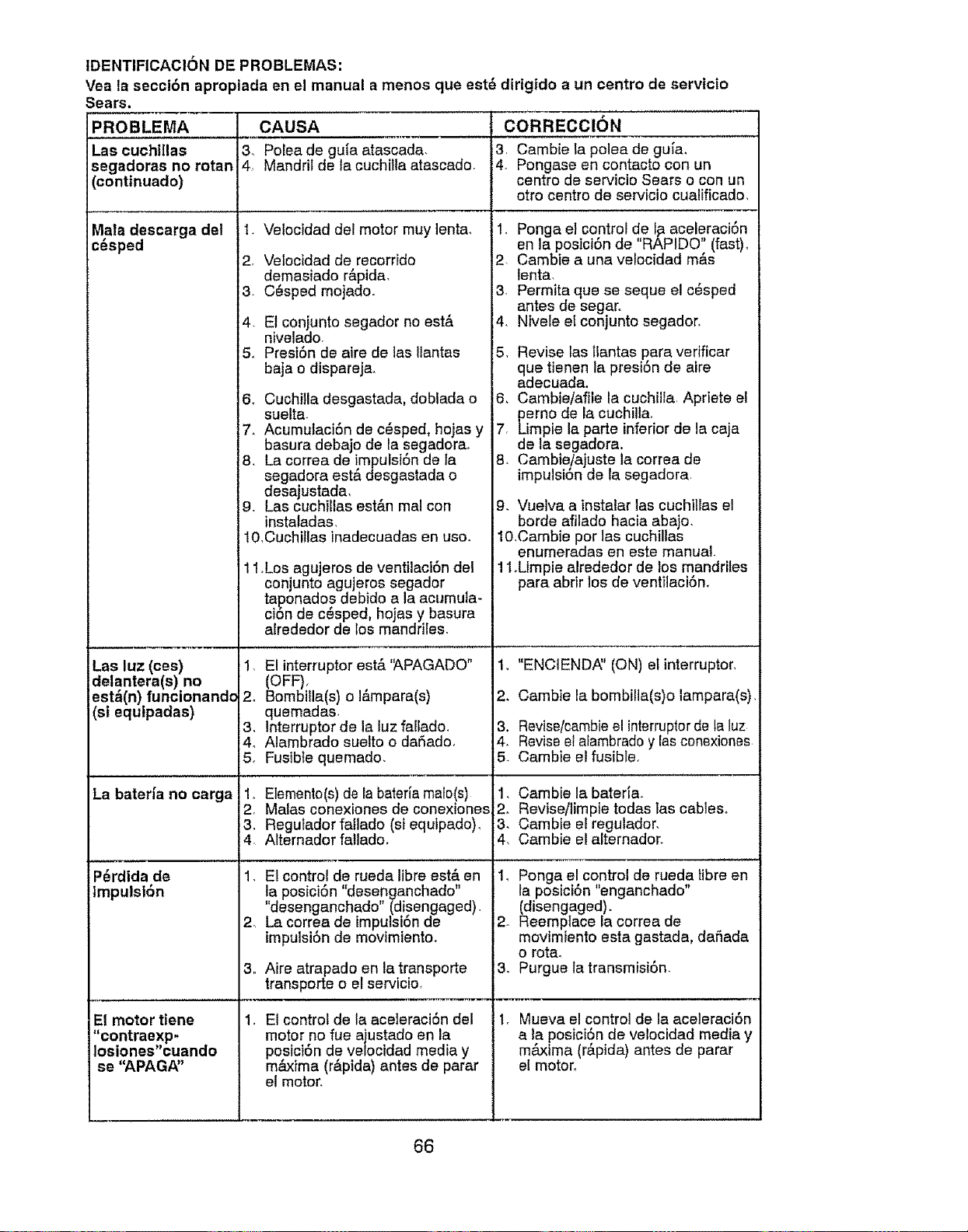
IDENTIFICACI6N DE PROBLEMAS:
Vea la seccibn apropiada en el manual a menos que est_ dirigido a un centro de servtc|o
Las cuchillas
;egadoras no rotan
continuado)
/lala descarga del
c_sped
Las luz (ces)
detantera(s) no
esta(n) funcionande
(si equlpadas)
La bateHa no carga
P6rdida de
tmpulst6n
El motor tiene
"contraexp-
Iosiones"cuando
se "APAG/V'
CAUSA
3, Polea de guia atascada,
4 Mandril de la cuchi}ta atascado.
1. Velocidad del motor muy lenta,
2. Velocidad de recorrido
demasiado r&pida.
3 CSsped mojado.
4, El conjunto segador no est&
nivelado.
5, Presi6n de aire de las Ilantas
baja o disparej&
6o CuchiIla desgastada, doblada o
suelta.
7. Acumutaci6n de c6sped, hojas y
basura debajo de la segadora.
8. La correa de impulsi6n de ta
segadora est& desgastada o
desajustada.
9. Las cuchillas est&n mal con
instaladas.
10.Cuchitlas inadecuadas en uso.
11.Los agujeros de ventilaci6n del
conjunto agujeros segador
taponados debido a la acumula-
cion de cesped, hojas y basura
alrededor de los mandriles.
!. E! interruptor est&'APAGADO"
(OFF).
2. Bombilla(s) o I&mpara(s)
quemadas.
3. lnterruptor de la tuz fallado.
4o Alambrado suelto o da_ado,
5, Fusible quemado,
1.. Elemento(s) de la bateria mate!s)
2. Malas conexiones de conexlones
. Regutador fatlado (si equtpado).
Alternador fatlado.
1. El control de rueda tibre est,. en
la posici6n "desenganchado"
"desenganchado" (disengaged).
2. La correa de impuisi6n de
impulsi6n de movimiento.
3o Aire atrapado en la transporte
transporte o el servicio.
, El control de la aceleraci6n del
motor no rue ajustado en la
po,sicion de ve/ocidad media y
maxima (r&pida) antes de parar
el motor.
CORRECCION
3, Cambie la polea de guia.
4. Pongase en contacto con un
centro de servicio Sears o con un
otro centro de servicio cualificado,
1. Ponga el control de I_ aceleraci6n
en la posicion de "RAPIDO" (fast).
2 Cambie a una velocidad m&s
lenta.
3 Permita qua se seque e! c6sped
antes de segar.
4. Ntvele el conjunto segador.
5. Revise las tlantas para vedficar
qua tienen la presi6n de aire
adecuada.
6. Cambie/afile la cuchillar Apriete el
perno de la cuchilla.
7. Limpie la parte inferior de la caja
de la segadora.
8. Cambie!ajuste la correa de
impulsion de la segadora.
9, Vuelva a instalar las cuchillas el
borde afilado hacia abajo.
lO,Cambie por 1as cuchiltas
enumeradas en este manual
1.Limpie alrededor de los mandriles
para abrir los de ventilaci6n.
1. "ENCIEND,_' (ON) el interruptor.
2. Cambie la bombilla(s)o lampara(s).
3. Revise/cambie el interruptordela luz
4. Revise el atambrado y las conexiones
5. Cambie el fusible.
1, Cambie la bateria_
2. Revise/limpie todas tas cables.
3, Cambie el regulador,
4, Cambie e! alternador.
I, Ponga el control de rueda libra en
la posici6n "enganchado"
(disengaged).
2_ Reemplace la correa de
movimiento esta gastada, dafiada
o rota.
3. Purgue la transmisi6n.
1. Mueva el control de la aceleraci6n
e la postci6n de velocidad media y
maxima (r&pida) antes de parar
el motor.
66
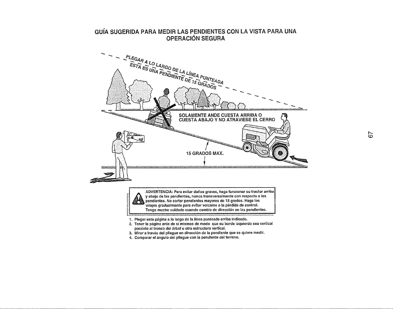
GU{A SUGERIDA PARA MEDIR LAS PENDIENTES CON LA VISTA PARA UNA
OPERACiON SEGURA
SOLAMENTE ANDE CUESTA ARRIBA O
CUESTA ABAJO Y NO ATRAVIESE EL CERRO
15 GRADES MAX.
1
t_
(D
_ DVERTENC{A: Pare evitar daSos graves, haga functonar su tractor arriba
y abajo de les pettdtentes_ nunca traneversaimente con respacto alas
pandientes. No eortar pendientes mayores de 15 grades. Haga foe
virajes gradualmente pare evitar voicarse o la perdida de control.
Tenga touche cutdade cuando cambie de direcci6n en las pendientes.
1. Plegar esta p_gtna a Io largo de la Ilnea punteeda arriba indicada.
2. Tenet la p_,g|naante de si m_smos de mode qua su horde izquierdo sea vertical
paralelo al tronco det _rbol u otra estructura vertical.
3. Mirar a traves del pliegue en direcct6n de la pendtente qua se qutere medtr.
4. Comparar el angule del pllegue con la pendtente del terrene.

Getit fixed, at your home or ours!
Your Home
For repair - in your home - of all major brand appliances,
lawn and garden equipment or heating and cooling systems,
no matter who made it, no matter who sold itX
For the re placement parts, accessories and
owner's manuals that you need to do-it-yourself.
For Sears professional installation of home appliances
and items like garage door openers and water heaters
1-800-4-MY-HOME ® Anytime, day or night
(1-800-469-4663) (US A and Canada)
www.sears,com www°sears.ca
Our Home
For repair of carry4n products like vacuums, lawn equipment,
and electronics, call or go on-line for the nearest
Sears Parts and Repair Center.
1-800-488-1222 Anytime day or night (USA only)
www, sears.com
To purchase a protection agreement (USA)
or maintenance agreement (Canada) on a product serviced by Sears:
1-800.827-6655 (u SA) t-800-361-6665 (Canada)
Para pedir servicio de reparaci6n
a domicilio, y para ordenar piezas:
1-888-SU-HOGAR ®
(14388-784-6427)
Au Canada pour service en franc..ais:
1-800-LE-FOYER Mc
(14300-533-6937)
www_sea[s ca
© SearsBrands,LLC
SealFS "
® Registered Trademark l rM Trademark t SMService Mark of Sears Brands, LLC
® Marce Registrada 1TMMarca de F_brica ! s_ Marca de Servicio de Sears Brands, LLC
Mc Marque de commerce t _r_Marque d_pos6e de Sears Brands, LLC
418410 11.28.07 BM Printed in U,S.A.


