(RI:IFTXMI:1N
MODEL NUMBER 917.256922 OWNER'S MANUAL
oAssembly
oOperation
oCustomer
Responsibilities
oService
oAdjustments
oRepair Parts
Caution:
Read and Follow
all Safety Rules
and Instructions
Before Operating
This Equipment
J
SAFETY RULES
Safe Operation Practices for Ride-On Mowers
IMPORI"ANT: THIS CUTTING MACHINE IS CAPABLE OFAMPUTAT1NG HANDS AND FEET AND TH ROWING OBJECTS,
FAILURE TOOBSERVETHE FOLLOWING SAFETY INSTRUCTIONS COULD RESULT IN SERIOUS INJURY OR DEATH.
I. GENERAL OPERATION
• Read, understand, and follow alt instructions in the manual
and on the machine before stagging.
• Only allow responsible adults, who are familiar with the
instructions, to operate the machine.
• Clear the area of objects such as rocks, toys, wire, etc.,
which could be picked up and thrown by the blade.
• Be sure the area is clear of other people before mowing. Stop
machine if anyone enters the area.
• Never carry passengers..
• Do not mow in reverse unless absolutely necessary. Always
look down and behind before and while backing
• Be aware of the mower discharge direction and do not point
it at anyone. Do not operate the mower without either the
entire grass catcher or the guard in place.
• Slow down before turning
• Never leave a running machine unattended Always turn off
blades, set parking brake, stop engine, and remove keys
before dismounting.
• Turn off blades when not mowing
• Stop engine before removing grass catcher or unclogging
chute.
• Mow only in daylight or good artificial fight..
• Do not operate the machine while under the influence of
alcohol or drugs.
• Watch for traffic when operating near or crossing roadways.
• Use extra care when loading or unloading the machine into
a trailer or truck.
II, SLOPE OPERATION
Slopes are a major factor related to loss-of-control and tipover
accidents, which can result in severe injury or death_ All slopes
require extra caution. If you cannot back up the slope orif you feel
uneasy on it, do not mow it
DO:
• Mow up and down slopes, not across
• Remove obstacles such as rocks, tree limbs, etc..
• Watch for holes, ruts, or bumps. Uneven terrain could
overturn the machine Taft grass can hide obstacles..
• Use stow speed Choose a low gear so that you will not have
to stop or shift while on the slope
• Follow the manufacturer's recommendations for wheel
weights or counterweights to improve stability
• Use extra care with grass catchers or other attachments.
These can change the stability of the machine.
• Keep all movement on the slopes slow and gradual. Do not
make sudden changes in speed or direction.
• Avoid starting or stopping on a.slope** If tires lose traction,
disengage the blades and proceed slowly straight down the
slope
DO NOT:
• Do not turn on slopes unless necessary, and then, turn slowly
and gradually downhill, if possible.
• Do not mow near drop-offs, ditches, or embankments. The
mower could suddenly tum over if a wheel is over the edge
of a ctiff or ditch, or if an edge caves in.
• Do not mow on wet grass Reduced traction could cause
sliding.
• Do not try to stabilize the machine by putting your foot on the
ground.
• Do not use grass catcher on steep slopes.
IlL CHILDREN
Tragic accidents can occur if the operator is not alert to the
presence of children. Children are often attracted to the machine
and the mowing activity Neverassume that children witl remain
where you last saw them.
• Keep children out of the mowing area and underthe watchful
care of anolher responsible adult.
• Be alert and turn machine off if children enter the area.
° Before and when backing, look behind and down for small
children.
• Never carry children. They mayfall off and be seriously
injured or interfere with safe machine operation
° Never allow children to operate the machine.
• Use extra care when approaching blind comers, shrubs,
trees, or other objects that may obscure vision
IV. SERVICE
° Use extra care in handling gasoline and other fuels. Theyare
flammable and vapors are explosive
Use only an approved container.
Never remove gas cap or add fuel with the engine
running. Allow engine to coot before refueling. Do not
smoke.
Never refuel the machine indoors.
Never store the machine or fuel container inside where
there is an open flame, such as a water heater.
- Never run a machine inside a closed area.
• Keep nuts and bolts, especially blade attachment bolts, tight
and keep equipment in good condition.
. Never tamper with safety devices.. Check their proper
operation regularly.
• Keep machine free of grass, leaves, orotherdebds build-up.
C_ean oil or fuet spillage. Allow machine to cool before
stodng.
- Stop and inspect the equipment if you strike an object.
Repair, if necessary, before restagging.
° Never make adjustments or repairs with the engine running
• Grass catcher components are subject to wear, damage, and
deterioration, which could expose moving parts or allow
objects to be thrown. Frequently check components and
replace with manufacturer's recommended parts, when nec-
essary
• Mower blades are sharp and can cut. Wrap the blade(s) or
wear gloves, and use extra caution when servicing them..
• Check brake operation frequently Adjust and service as
required.
LOOkfor thistly"rebel to point out impor-
tant safety precautions, It means
CAUTION_H BECOME ALERTH! YOUR
SAFETY tS INVOLVED.
CAUTION: Always disconnect spark
plug wire and place wire where it cannot
contact spark plug in order to prevent
accidental starting when setting up,
transporting, adjusting or making
repairs.
i,i H, HII
CONGRATULATIONS on your purchase of a Sears trac-
tor,. It has been designed, engineered and manufactured
to give you the best possible dependability and perfor-
mance.
Should you experience any problem you cannot easily
remedy, please contact your nearest Sears Service
Center/DepartmenL We have competent, well4rained
technicians and the proper tools to service or repair this
tractor.
Please read and retain this manual.. The instructions will
enable you to assemble and maintain your tractor prop-
erly_ Always observe the "SAFETY RULES".
MODEL
NUMBER 917256922
SERIAL
NUMBER
DATE OF PURCHASE
THE MODEL AND SERIAL NUMBERS WILL BE FOUND
ON A PLATE UNDER THE SEAT.
YOU SHOULD RECORD BOTH SERIAL NUMBER AND
DATE OF PURCHASE AND KEEP IN A SAFE PLACE
FOR FUTURE REFERENCE
PRODUCT SPECIFICATIONS
HORSEPOWER: 12
GASOLINE CAPACITY: 14 GALLONS
UNLEADED REGULAR
OIL (3.0 PINTS) SAE 30 (above 32°F)
5W-30 (below 32°F)
SPARK PLUG (GAP 030 IN.): CHAMPION RJ-19LM
STD361458
VALVE CLEARANCE: INTAKE. 005 - .007 IN
EXHAUST ,009 - .011 IN.
GROUND SPEED: FORWARD
1st .95 MPH
2rd 194 MPH
3th 2491 MPH
4th 3.71 MPH
5th 4 76 MPH
REVERSE: 1.46 MPH
TIRE PRESSURE: FRONT: 14 PSI
REAR: 12 PSI
CHARGING SYSTEM: 5 AMPS HEADLIGHTS
3 AMPS BATTERY
BLADE BOLT TORQUE: 30-35 FT,.LBS
MAINTENANCE AGREEMENT
A Sears maintenance agreement is available on this trac-
tor. Contact your nearest Sears store for details.
CUSTOMER RESPONSIBILITHES
= Read and observe the safety rules.
. Fotlow a regular schedule in maintaining, caring for and
using your tractor.
• Fotlowthe instructions under"Customer Responsibili-
ties" and "Storage" sections of this manual.
WARNING: This tractor is equipped with an internal
combustion engine and should not be used on or near any
unimproved forest-covered, brush-covered or grass-cov-
ered land unless the engine's exhaust system is equipped
with a spark arrester meeting applicable local or state laws
(if any). If a spark arrester is used, it should be maintained
in effective working order by the operator,
In the state of California the above is required by law
(Sect on 4442 of the California Public Resources Cede).
Other states may have similar laws. Federal laws apply on
federal lands. A spark arrester for the muffler is available
through your nearest Sears autho rized service center (See
REPAIR PARTS section of this manual)°
LIMITED TWO YEAR WARRANTY ON ELECTRIC START RIDING EQUIPMENT
For two (2) years from the date of purchase, if this riding equipment is maintained, lubricated and tuned up according to the
instructions in the owneCs manual, Sears will repair or replace, free of charge, any parts found to be defective in material or
workmanship.
This Warranty does not cover:
* Expendable items which become worn during normal use, such as blades, spark plugs, air cleaners and belts.
. Tire replacement or repair caused by punctures from outside objects,such as nails, thorns, stumps, or glass.
, Repairs necessary because of operator abuse, negligence, improper storage or accident or the failure to maintain the
equipment according to the instructionscontained in the owner's manual . ........
, Riding equipment used forcommercia,[orrental purposes.[ ""
LIMITED 90 DAY WARRANTY ON BATTERY
For 90 days from date of purchase, if any battery included with thisriding equipment proves defective in material or workmanship
and our testingdetermines the battery wil!not hold a charge, Sears will replace the battery at no charge.
WARRANTY SERVICE IS AVAILABLE BY RETURNING THE RIDING EQUIPMENT TO THE NEAREST SEARS SERVICE
CENTER/DEPARTMENT IN THE UNITED STATES,,
This Warranty gives you specific legal rights, and you may atso have other rights which may vary from state to state
SEARS, ROEBUCK AND CO. D/817 WA, HOFFMAN ESTATES, ILLINOIS 60179
, , i lU i,,Ul
3
TABLE OF CONTENTS
......... i...... i,,i,, ........................................... iii ,Ull
SAFETY RULES ............................................................ 2
PRODUCT SPECIFICATIONS ...................................... 3
CUSTOMER RESPONSIBILITIES ..................... 3, 14-'17
WARRANTY ................................................................ .3
TABLE OF CONTENTS ................................................ 4
INDEX ............................................................................ 4
TRACTOR ACCESSORIES .......................................... 5
ASSEMBLY ................................................................. 7-9
OPERATION ........................................................... 10-'13
MAINTENANCE SCHEDULE ...................................... 14
SERVICE AND ADJUSTMENTS ............................ 18-22
STORAGE ................................................................... 23
TROUBLESHOOTING ........................................... 24,-25
REPAIR PARTS - TRACTOR ................................ 27-43
REPAIR PARTS - ENGINE .................................... 46-50
PARTS ORDERING/SERVICE .................. BACK PAGE
aNDEX
A
Accessories .............................................. 5
Adjustments:
Brake ............................................... 20
Carburetor ....................................... 22
Mower
Front-To-Back ............................... 1 9
Side-To-Side ............................ 19
Throttle Control Cable ........................22
Air Filter, Engine ................................... 17
Air Screen, Engine .............................. 17
Assembly ............................................... 7-9
B
Battery:
Charging ......................................... 8
Cleaning ...... .....................................16
Installation...................................... 9
Leve Is ............................... ............ 8,15
Preparation ............................................8
Starting with Weak Battery ............21
Storage ...............................................23
Terminals ..........................................16
Belt:
Motion Drive
Removal/Replacement ........... 20
Blade:
Sharpening ................................. 15
Replacement ................................... 15
Brake Adjustment .............................. 20
C
CarburetorAdjustment ........................ 22
Controls, Tractor .................................. 10
C ustome r Responsibitities ............3,14-17
Engine:
Air Filter .................................. 17
Air Filter Foam Pre-Cfeaner .....17
Air Screen, Engine ................. 17
Battery ........................................ 15
Cooling Fins, Engine .............. 17
Engine Oil ......................... 16
Fuel Filter ............................... 17
Spark Plugs ........................... 17
Tractor:
Blade .......................................... 15
Lubrication Chart .................... 14
Maintenance Schedule ............ 14
Tire Care ....................... 8,15,2t
Cutting Height, Mower ....................... 12
E
Electrical:
Interlocks and Relays ................ 21
Schematic ...........................................26
Wiring Diagram ......................... 28
Engine:
Air Filter .............................................17
Air Filter Foam Pre-Cleaner .............17
Air Screen ...................................... 17
Cooling Fins, Engine .......................17
Oil Change .......................................16
Oil Level .................................... 12,16
Oil Type ........................................... 16
Preparation ................................ 12
Repair Parts ............................ 46-50
Starting ........................................... t 3
Storage ............................................ 23
F
Filter:
Air Filter ........................................... t7
Air Filter Foam Pre-Oleaner ............17
Fuel ............................................ 17
Fuel:
Type ............................................... 13
Storage .................................. ............ 23
Fuse ............................................................... 21
H
Hood Removal/Installation ........ 21
L
Leveling Mower Deck ..............................19
Lubrication:
Chart ....................................................t4
M
Maintenance Schedule ..................... I 4
Mower:
Adjustment, Front4o-Back ........... 19
Adjustment, Side-to-Side ............ 19
Blade Sharpening ..................... 15
Blade Replacement ..........................15
Cutting Height ................................ 12
Installation ..............................:_....... 18
Operation ............................................12
Removal ......................................... 18
Mowing Tips ............................................ 13
Muffler ........................................... 17
Spark Arrester ........................... 3,38
O
Oil:
Cold Weather Conditions .........12,16
Engine .....................................................16
Storage ....................................................23
Operation ........................................ 10-13
Operating Mower ........................................... 12
Options:
Accessodes .................................... ............... 5
Spark Arrester ............................... 3,38
P
Parking Brake ........................................10-11
Parts Bag .............................................................6
Pads, Replacement/Repair ...............27-43
Product Specifications ..................................3
R
Repair Parts ..............................................27-43
S
Safety Rules .....................................................2
Seat ................................................................ 8
Service and Adjustments ............... 18-22
Carburetor ........................................ 22
Fuse ................................... ............... 21
Hood RemovaVlnstallation ..............21
Motion Drive Belt
RemovaltReplacement ............ 20
Mower Adjustment:
Front- to-Back .......................... 19
Side4o-Side ...................................19
Mower Removal ............................ !8
Tire Care ................................ 8,15,21
Slope Guide Sheet ............................... 51
Spark Plugs ...................................................t7
Specifications ............................... ..................... 3
Starting the Engine ........................... 12-13
Steering Wheel .........................................7,20
Stopping the Tractor ..................................11
Storage ..................................................23
T
Throttle Control Cable Adjustment -_ 22
Tires ............................................. 8,15,21
Trouble Shooting Chart ......................24-25
Transaxle Repair Parts .....................44-45
W
Warranty ................................................... 3
Wiring Diagram ...................................... 28
Wiring Schematic ............................... 26
, H=I H, , , =I,"H'H ............................ I I II I I=INH,H=
ACCESSORIES AND ATTACHMENTS
.......................... i IIIIIIH= N,=,II= ii 1,1111111,11
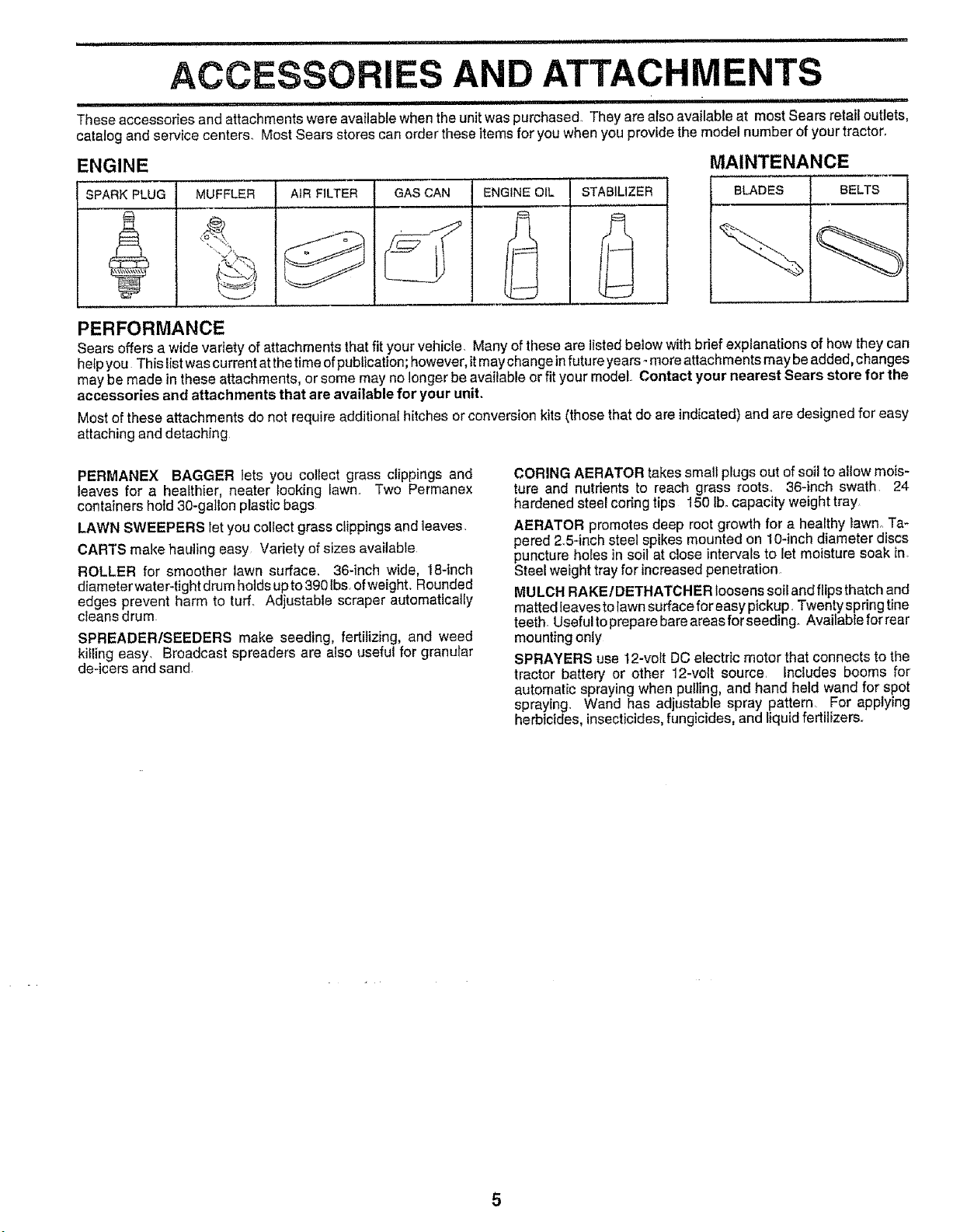
These accessories and attachments were available when the unit was purchased. They are also available at most Sears retail outlets,
catalog and service centers. Most Sears stores can order these items for you when you providethe model number of your tractor.
ENGINE
SPARK PLUG MUFFLER AiR FILTER GAS CAN ENGINE OIL STABILIZER
MAINTENANCE
BLADES 1 BELTS
PERFORMANCE
Sears offersa widevarietyof attachments thatfit your vehicle, Manyof these are listedbelow withbrief explanationsof how they can
he_pyou Thislistwascurrentatthetimeofpublication; however, itmay changeinfuture years° moreattachments may beadded,changes
may be made in these attachments, or some may no longerbe available or fit your model Contact your nearest Sears store for the
accessories and attachments that are available for your unit.
Most of these attachments do not require additional hitches or conversion kits (those that do are indicated)and are designed for easy
attaching and detaching
PERMANEX BAGGER lets you collect grass clippings and
leaves for a healthier, heater looking iawn., Two Permanex
containers hold 30-gallon plastic bags
LAWN SWEEPERS let you coliect grass clippings and leaves,
CARTS make hauiing easy Variety of sizes available
ROLLER for smoother lawn surface. 36-inch wide, 18-inch
diameter water-tight drum holds up to 390 tbs of weight, Rounded
edges prevent harm to turf_ Adjustable scraper automatically
cleans drum.
SPREADER/SEEDERS make seeding, fertilizing, and weed
kitling easy, Broadcast spreaders are also useful for granular
de-icers and sand,
CORING AERATOR takes small plugsout of soil to allow mois-
ture and nutrients to reach grass roots. 36-inch swath. 24
hardened steel coring tips 150 lb. capacity weight tray
AERATOR promotes deep root growth for a healthy lawno Ta-
pered 2_5-inchsteel spikes mounted on t 0-inch diameter discs
puncturehofes in soil at close intervals to let moisture soak in_
Steel weight tray for increased penetration.
MULCH RAKE/DETHATCHER loosens soil and flips thatch and
matted leaves to lawn surface for easy pickup. Twentyspring tine
teeth. Useful topreparebare areas for seeding. Available for rear
mounting only
SPRAYERS use 12-volt DC electric motor that connects to the
tractor battery or other 12-volt source Includes booms for
automatic spraying when pulling,and hand held wand for spot
spraying. Wand has adjustable spray pattern For applying
herbicides, insecticides,fungicides, and liquid fertilizers_
i ,=,,=, IHH'H
CONTENTS OF
,,,=,,,i,=,,i i .........................
HARDWARE PACK
..... t, ,,u=
,,u,,,,H
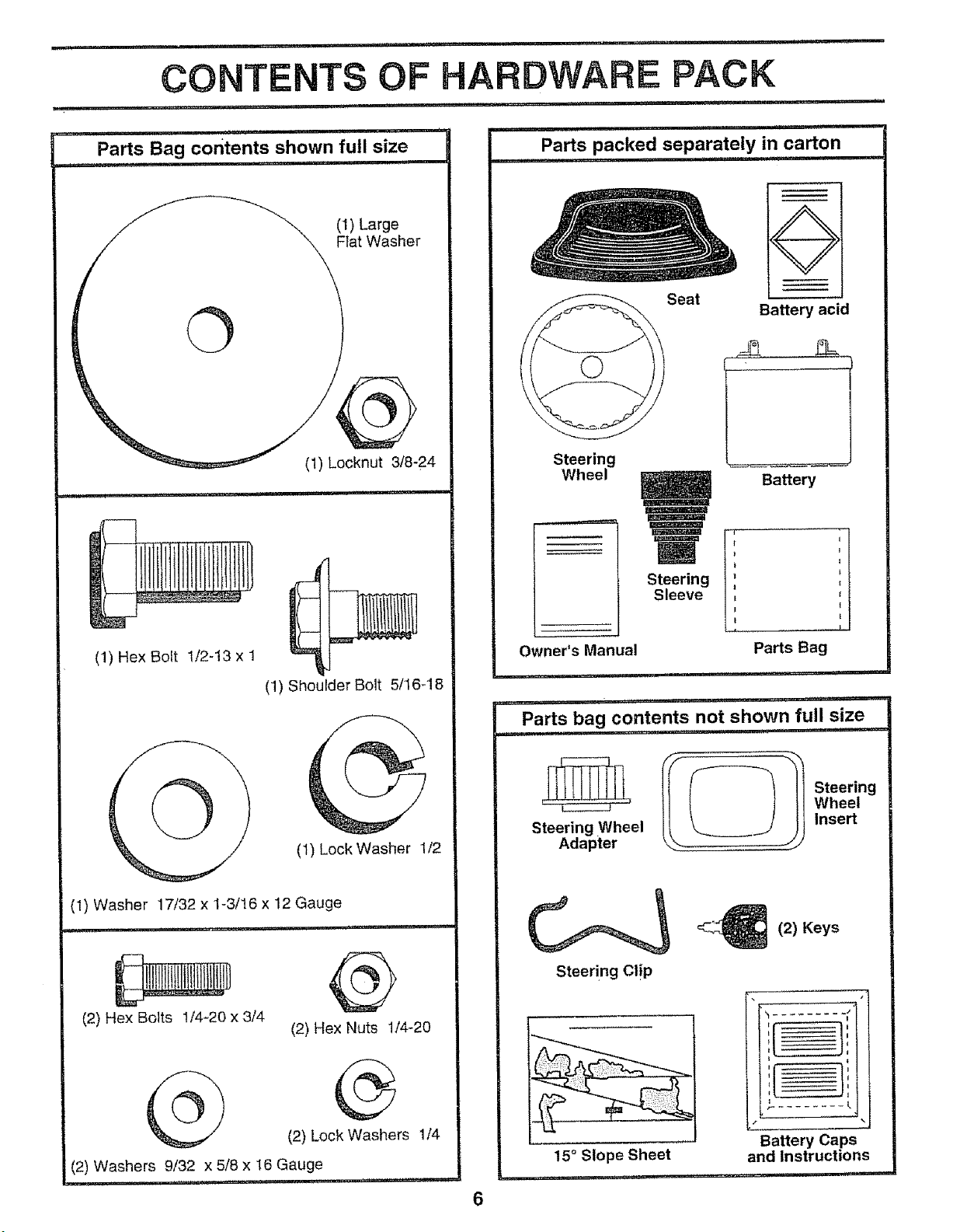
Parts packed separately in carton
,1 ....
_ ,ul,,=
Parts Bag contents shown full size
............. ==,,, =
©
(1) Large
Flat Washer
(1) Locknut 3/8-24
(1) Hex Bolt 1/2-13 x 1
(1) Shoulder Bolt 5/16-18
(1) Lock Washer 'I/2
(1) Washer 17/32 x 1-3/16 x 12 Gauge
= ,,,nN,I ' U',"11',1 =.... n'l
@
(2) Hex Nuts 1f4-20
(2) Hex Bolts 1/4-20 x 3/4
®
(2) Lock Washers 1/4
(2) Washers 9/32 x 5/8 x 16 Gauge
.... 1,1
Steering
Wheel
Seat
Steering
Sleeve
O
Battery acid
Battery
,1==
Owner's Manual
Parts Bag
i,, ='=' , m,,,
i ,,1=1, ,,=, ],,l.,rl_ .... i=' i"
Parts bag contents not shown full size
, =,H =,,u, _=--
II_f- _ll Steering
_ ' Wheel
Steering Wheel Insert
Adapter
Steering CliP
15° Slope Sheet
,=,
2) Keys
i i
L__
Battery Caps
and Instructions
,,, =
ASSEMBLY
' i -=, ,=,,,,, .... =1 ,,
Your new tractor has been assembled at the factory with the exception of those parts left unassembled for shipping purposes.
To ensure safe and proper operation of your tractor, all parts and hardware you assemble must be tightened securely. Use
the correct tools as necessary to insure proper tightnes&
TOOLS REQUIRED FOR ASSEMBLY
A socket wrench set will make assembly easier, Standard
wrench sizes are listed,,
(1) 9/16" wrench
(2) 7/16" wrenches
(1) 1/2" wrench
(1) 3/4" wrench
Pliers
Tire pressure gauge
Screwdriver
Utility knife
When right and left hand are mentioned in this manual, it
means when you are in the operating position (seated
behind the steering wheel).,
TO REMOVE TRACTOR FROM CARTON
UNPACK CARTON
o Remove all accessible loose parts and parts Cartons
from carton (See page 6)_
o Cut along lines on the carton, from top to bottom, all
four corners of carton and lay panels flat,
- Check for any additional loose parts or cartons and
remove,,
BEFORE ROLLING TRACTOR OFF SKID
ATTACH STEERING WHEEL
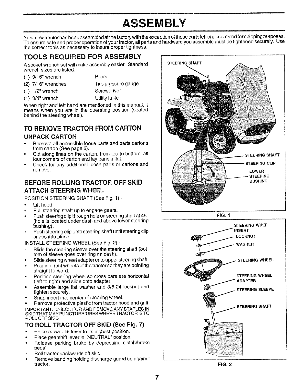
POSITION STEERING SHAFT (See Fig, 1) -
, Lift hood.
• Pull steering shaft up to engage gears..
o Push steering clip through hole on steering shaft at 45 °
(hole is located under dash and above lower steering
bushing),
o Push steering clip onto steering shaft until steering clip
snaps into place,,
INSTALL STEERING WHEEL (See Fig, 2) -
o Slide the steering sleeve over the steering shaft (bot-
tom of sleeve goes over ring on dash).
o Slide steering wheel adapter onto upper steering shaft,
o Position front wheels of the tractor so they are pointing
straight forward°
• Position steering wheel so cross bars are horizontal
(teft to right) and slide onto adapter.
o Assemble large flat washer and 3/8-24 locknut and
tighten securety.
- Snap insert into center of steering wheel°
, Remove protective plastic from tractor hood and grill,
IMPORTANT: CHECK FOR AND REMOVE ANY STAPLES IN
SKID THAT MAY PUNCTURE TIRES WHERE TRACTOR ISTO
ROLL OFF SKID
TO ROLL TRACTOR OFF SKID (See Fig. 7)
• Raise mower lift lever to its highest position,
o Place gearshift lever in "NEUTRAL" position.
,, Release parking brake by depressing clutch/brake
pedal
• Roll tractor backwards off skid
• Remove banding holding discharge guard up against
tractor.
STEERING SHAFT
STEERING CLIP
LOWER
STEERING
BUSHING
FIG. 1
STEERING WHEEL
STEERING WHEEL
STEERING WHEEL
FIG. 2
ii lU ....... i,U,UlUll,,nll,,,,n..... ii,l,,ll,ii I " I,'1
ASSEMBLY
..... i .................. ,M,,
HOW TO SET UP YOUR TRACTOR
PREPARE BATTERY (See Fig, 3)
CAUTION: Wear eye and face shield.
Wash hands or clothing immediately if
accidentally in contactwith battery acid.
Do not smoke. Fumes from charged
battery acid are explosive.
Read the instructions included with the
battery vent caps. Always wear gloves,
clothing and goggles to protect your
hands, skin and eyes.
..... =....
Your tractor has a battery charging system which is suffi-
cient for normal use° However, periodic charging of the
battery with an automotive charger will extend its lifeo
o See instructions packed with vent caps in parts bag.
- Fill battery with acid. Fill each cell until it reaches the
bottom of the vent wells. Do not overfill
o Allow battery to stand and settle for at least thirty
minutes, After standing, check the level of acid. If
below the vent wells, add more acid until the correct
level is reached.
While battery is standing (after adding acid) and later, while
battery is being charged, continue with assembly of tractor_
IMPORTANT: TO MAXIMIZE THE LIFE OF YOUR BATTERY,
IT IS NECESSARY THAT THE BATTERY BE CHARGED
BEFOREUSE, FAILURETO CHARGE BATTERYCAN RESULT
IN A SHORTENED BATTERY LIFE.,
• Charge battery at a rate of 6 amperes for 1 hour. Use
a 12 volt battery charger., Observe alt safety precau-
tions required for battery charging.
o Check the acid level after the battery is charged, If the
acid has faflen below the correct level, add distilled or
iron free water.
. Install the vent caps to cover the vent wells,, Wash the
top of the battery with water to remove any acid, then
wipe dry.
o Check battery case for leakage to make sure that no
damage has occurred in handling,,
o Dispose of excess battery acid,. Neutralize acid for
disposal by adding it to four inches of water in a five
gallon plastic container. Stir with a wooden or plastic
paddle while adding baking soda until the addition of
more soda causes no more foaming,
• Foliow instructions on how to install battery_
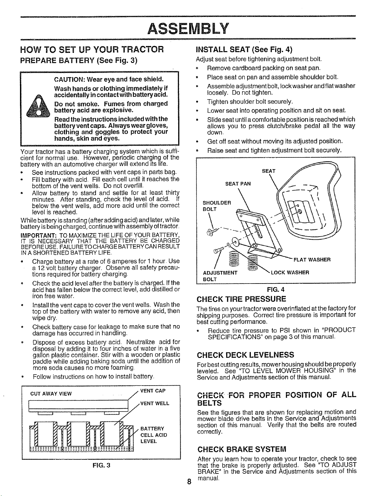
INSTALL SEAT (See Fig. 4)
Adjust seat before tightening adjustment bolt.
o Remove cardboard packing on seat pan_
,, Place seat on pan and assemble shoulder bolt.
° Assemble adjustment bolt, lockwasher andfiatwasher
loosely,, Do not tighten.
= Tighten shoulder bolt securely.
° Lower seat into operating position and sit on seat,,
. Slide seat until a comfortable position is reached which
allows you to press clutch/brake pedal all the way
down.
° Get off seat without moving its adjusted position.
o Raise seat and tighten adjustment bolt securely.
SEAT
SEAT PAN
SHOULDER
BOLT
FLAT WASHER
ADJUSTMENT LOCK WASHER
BOLT
FIG. 4
CHECK TIRE PRESSURE
The tires on you r tractor were overinflated at the factory for
shipping purposes. Correct tire pressure is important for
best cutting performance.
- Reduce tire pressure to PSI shown in "PRODUCT
SPECIFICATIONS" on page 3 of this manual.
CHECK DECK LEVELNESS
For best cutting results, mower housing should be properly
leveled. See "TO LEVEL MOWER HOUSING" in the
Service and Adjustments section of this manual.
CUT AWAY VIEW
VENT CAP
VENT WELL
BATTERY
CELL ACID
LEVEL
FIG. 3
CHECK FOR PROPER POSiTiON OF ALL
BELTS
See the figures that are shown for replacing motion and
mower blade drive belts in the Service and Adjustments
section of this manual. Verify that the belts are routed
correctly,
CHECK BRAKE SYSTEM
After you learn how to operate your tractor, check to see
that the brake is properly adjusted. See "TO ADJUST
BRAKE" in the Service and Adjustments section of this
manual,
...... ,,,-, , ................ -,,,,,,,i, ii iiiii1,,,11 i ,,
ASSEMBLY
+
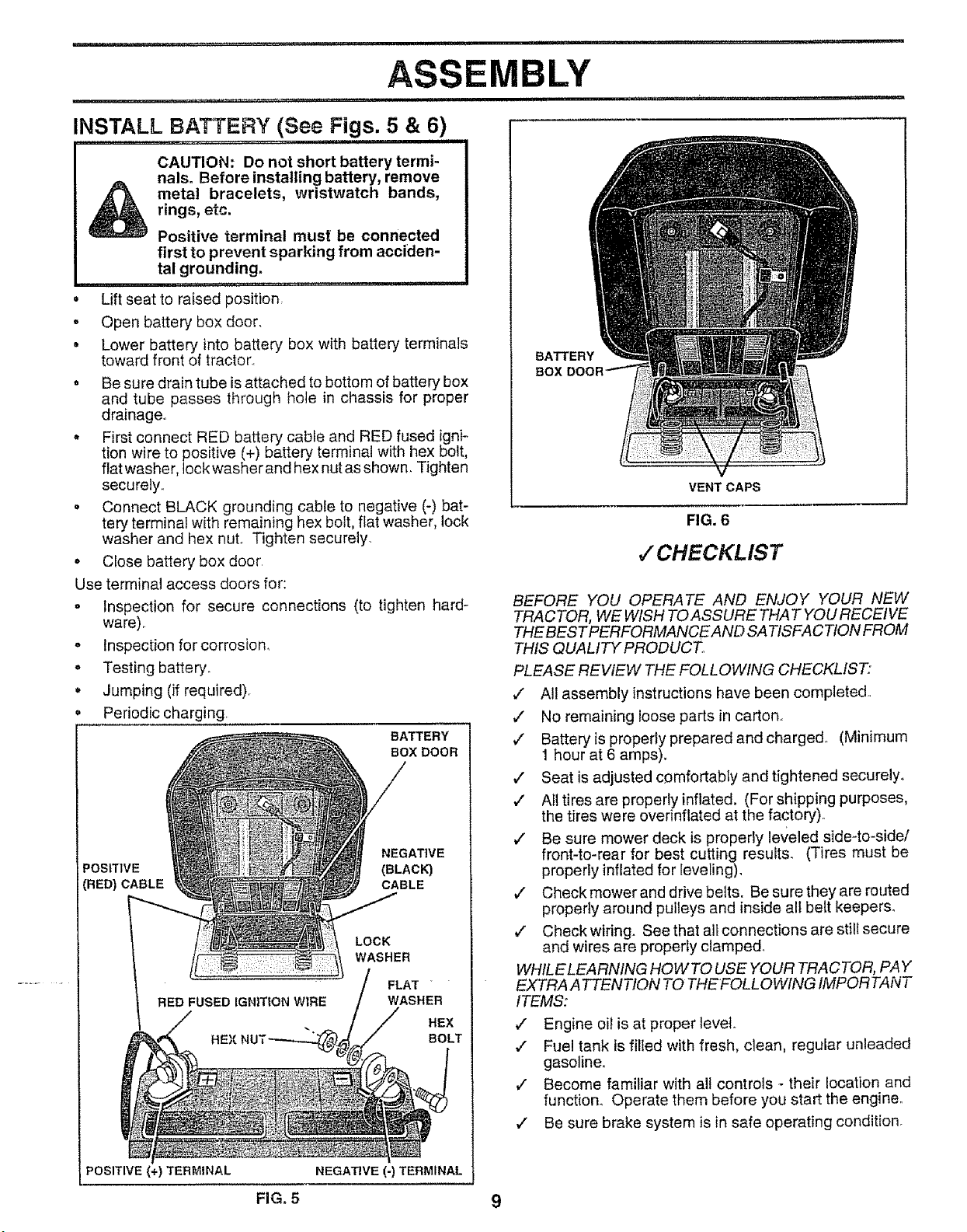
INSTALL BATTERY (See Figs. 5 & 6)
........ i i,iiiiiiii
CAUTION: Do not short battery termi-
nals+ Before installing battery, remove
metal bracelets, wristwatch bands,
rings, etc.
Positive terminal must be connected
first to prevent sparking from acciden-
tal grounding.
.... =,=1,, ,............. , ........
Lift seat to raised position
* Open battery box door.
, Lower battery into battery box with battery terminals
toward front of tractor..
o Be sure drain tube is attached to bottom of battery box
and tube passes through hole in chassis for proper
drainage.
, First connect RED battery cable and RED fused igni-
tion wire to positive (+) battery terminal with hex bolt,
flat washer, lock washer and hex nut as shown. Tighten
securely..
o Connect BLACK grounding cable to negative (-) bat-
tery terminal with remaining hex bolt, flat washer, lock
washer and hex nut+ Tighten securely.
+ Close battery box door
Use terminal access doors for:
o Inspection for secure connections (to tighten hard +
ware).
- Inspection forcorrosion_
o Testing battery+
+ Jumping (if required)
Periodic charging.
BATTERY
BOX DOOR
NEGATIVE
POSITIVE (BLACK)
(RED) CABLE CABLE
HEX
LOCK
WASHER
FLAT
WASHER
HEX
BOLT
POSITIVE (+) TER&,_INAL NEGATIVE (-) TERMINAL
BATTERY
BOX
VENT CAPS
FIG. 6
,/CHECKLIST
BEFORE YOU OPERATE AND ENJOY YOUR NEW
TRACTOR, WE WISH TO ASSURE THAT YOU RECEIVE
THE BESTPERFORMANCEAND SATISFACTION FROM
THIS QUALITY PRODUCT,
PLEASE REVIEW THE FOLLOWING CHECKLIST:
J All assembly instructions have been completed.,
¢' No remaining loose parts in carton,,
¢' Batteryis properly prepared and charged,, (Minimum
1 hour at 6 amps)+
v" Seat is adjusted c_mfortably and tightened securely.
v" All tires are properly inflated. (For shipping purposes,
the tires were overinflated at the factory).
¢' Be sure mower deck is properly leveled side-to-side/
front4o-rear for best cutting results+ (Tires must be
properly inflated for leveling).
v" Check mower and drive belts. Be sure they are routed
properly around pulleys and inside all belt keepers.
¢" Check wiring. See that all connections are still secure
and wires are properly clamped+
WHtLE LEARNING HOW TO USE YOUR TRACTOR, PAY
EXTRA A TTENTION TO THEFOLLOWING IMPORTANT
ITEMS:
,/ Engine oil is at proper level.
_" Fuel tank is filled with fresh, clean, regular unleaded
gasoline.
,/ Become familiar with all controls + their location and
function. Operate them before you start the engine.
,/ Be sure brake system is in safe operating condition.
FroG+5 9
OPERATION
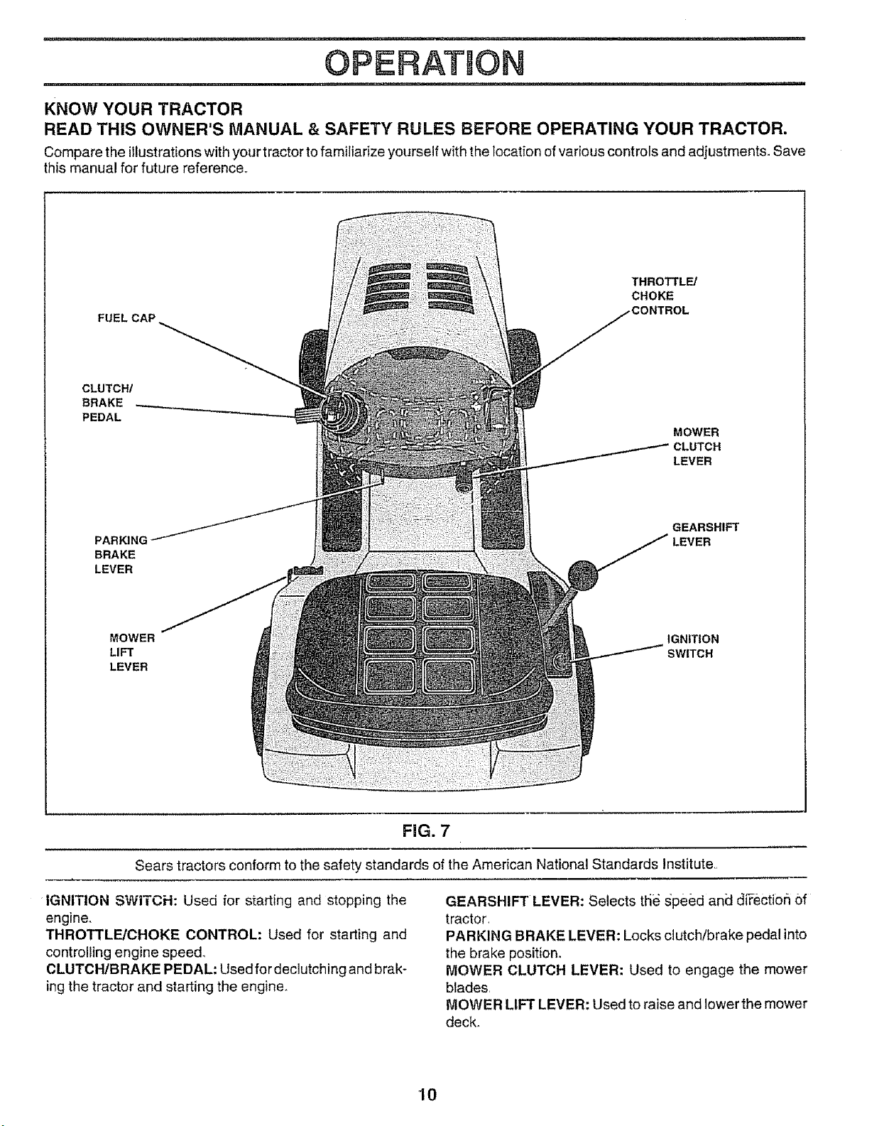
KNOW YOUR TRACTOR
READ THIS OWNER'S MANUAL & SAFETY RULES BEFORE OPERATING YOUR TRACTOR.
Compare the illustrations with your tractor to familiarize yourself with the Iocation of various controls and adjustments. Save
this manual for future reference_
FUEL CAP
THROTTL_
CHOKE
_TROL
CLUTCH/
BRAKE
PEDAL
MOWER
LEVER
PARKING
BRAKE
LEVER
GEARSHIFT
LEVER
MOWER IGNITION
LIFT SWITCH
LEVER
FiG. 7
Sears tractors conform to the safety standards of the American National Standards Institute,
IGNITION SWITCH: Used for starting and stopping the
engine.
THROTTLE/CHOKE CONTROL: Used for starting and
controlling engine speed,
CLUTCH/BRAKE PEDAL: Usedfor declutching and brak-
ing the tractor and starting the engine.
GEARSHIFT LEVER: Selects tlie gpe_)d and di_ectiorl Of
tractor,
PARKING BRAKE LEVER: Locks clutch/brake pedal into
the brake position,
MOWER CLUTCH LEVER: Used to engage the mower
blades
MOWER LIFT LEVER: Used to raise and lower the mower
deck°
10
OPERATION
iii , ,i,1,11 i iii ii1,1,11111111111111
The operation of any tractor can result in foreign objects thrown into the eyes, which can result
in severe eye damage, Always wear safety glasses or eye shields before starting your tractor
and while moving. We recommend wide vision safety mask for over the spectacles or standard
safety glasses.
HOW TO USE YOUR TRACTOR
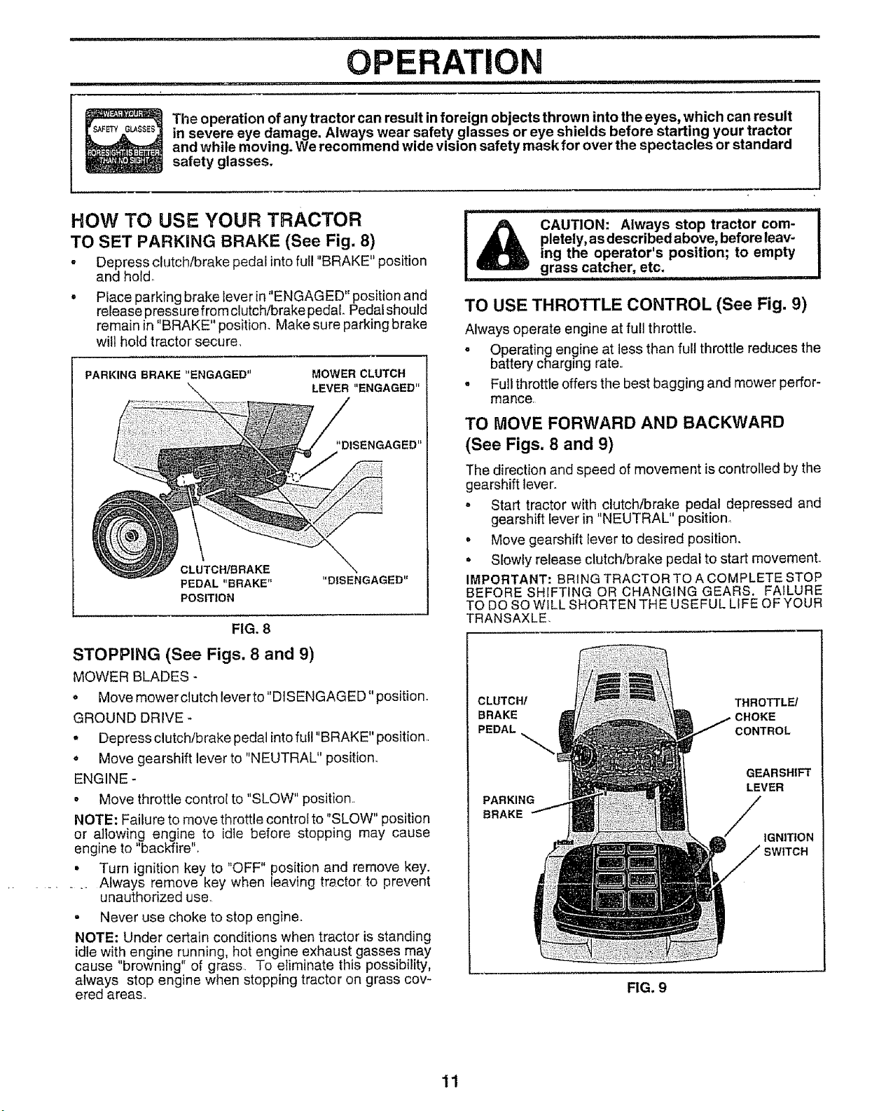
TO SET PARKING BRAKE (See Fig. 8)
° Depress clutch/brake pedal into full "BRAKE" position
and hold.
° Place parking brake leverin"ENGAGED" position and
release pressure from clutch/brake pedal Pedal should
remain in "BRAKE" position_ Make sure parking brake
wilt ho_d tractor secure
PARKING BRAKE"ENGAGED" MOWER CLUTCH
LEVER"ENGAGED"
'*DISENGAGED"
CLUTCH/BRAKE
PEDAL"BRAKE"
POSITION
FIG. 8
STOPPING (See Figs. 8 and 9)
MOWER BLADES -
° Move mower clutch lever to "DISENGAGED" position.
GROUND DRIVE
• Depress clutch/brake pedal into full "BRAKE" position,
o Move gearshift lever to "NEUTRAL" position.
ENGINE -
• Move throttle contro{ to "SLOW" position.
NOTE: Failure to move throttle control to "SLOW" position
or allowing engine to idle before stopping may cause
engine to "backfire",
° Turn ignition key to "OFF" position and remove key.
......... Always remove key when Leaving trsctor to prevent
unauthorized use.
= Never use choke to stop engine.
NOTE: Under certain conditions when tractor is standing
idle with engine running, hot engine exhaust gasses may
cause "browning" of grass To etiminate this possibility,
always stop engine when stopping tractor on grass cov-
ered areas,,
inln I u "J
CAUTION: Always stop tractor com-
I
pletely, as described above, before leav-
ing the operator's position; to empty
grass catcher, etc.
i ii, i,i1,1,1111,11,1,,111 i iii iii,
TO USE THROTTLE CONTROL (See Fig. 9)
Always operate engine at full throttle.
o Operating engine at less than full throttle reduces the
battery charging rate,,
. Full throttte offers the best bagging and mower perfor-
mance
TO MOVE FORWARD AND BACKWARD
(See Figs. 8 and 9)
The direction and speed of movement is controlled by the
gearshift lever.
= Start tractor with clutch/brake pedal depressed and
gearshift Iever in "NEUTRAL" position,,
= Move gearshift lever to desired position.
° Slowly release clutch/brake pedal to start movement.
IMPORTANT: BRING TRACTOR TO A COMPLETE STOP
BEFORESH[FTING OR CHANGING GEARS, FAILURE
TO DO SO WiLL SHORTEN THE USEFUL LIFE OF YOUR
TRANSAXLE.
CLUTCH/ THROTTLE/
BRAKE
PEDAL CONTROL
PARKING
BRAKE
GEARSHIFT
LEVER
IGNITION
FIG. 9
11
U'I
OPERATION
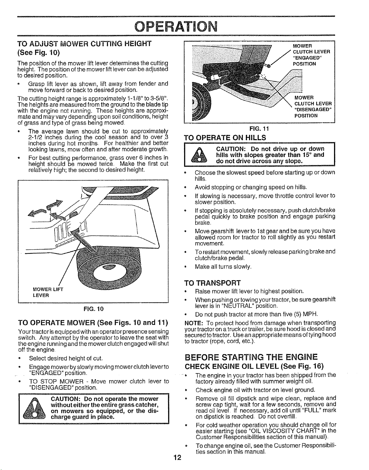
TO ADJUST MOWER CUTTING HEIGHT
(See Fig. 10)
The position of the mower lift lever determines the cutting
height° The position of the mower Iift lever can be adjusted
to desired position.
o Grasp lift Iever as shown, lift away from fender and
move forward or back to desired position,.
The cutting height range is approximately 1-t/8" to 3-5/8".
The heights are measured from the ground to the blade tip
with the engine not running. These heights are approxi-
mate and may vary depending upon soil conditions, height
of grass and type of grass being mowed.
• The average lawn should be cut to approximately
2-1/2 inches during the cooI season and to over 3
inches during hot months. For healthier and better
looking lawns, mow often and after moderate growth.
. For best cutting performance, grass over 6 inches in
height should be mowed twice Make the first cut
relatively high; the second to desired height.
MOWER LIFT
LEVER
FIG. 10
TO OPERATE MOWER (See Figs. 10 and 11)
Your tractor is equipped with an operator presence sensing
switch,. Any attempt by the operator to leave the seat with
the engine running and the mower clutch engaged will shut
off the engine.
o Select desired height of cut.
• Engage mower by slowly moving mower clutch lever to
"ENGAGED" position.
• TO STOP MOWER - Move mower clutch lever to
"DISENGAGED" position.
,,, , ,,,,,, ...........
CAUTION: Do not operate the mower
without either the entire grass catcher,
on mowers so equipped, or the dis-
charge guard in place.
=== ............
MOWER
CLUTCH LEVER
"ENGAGED"
POSITION
MOWER
CLUTCH LEVER
"DISENGAGED"
POSITION
Q
12
FIG. 11
TO OPERATE ON HILLS
= i ,, ,,1,,, •
I _% CAUTION: Do not drive up or down
I
hills with slopes greater than 15° and I
do not drive across any slope: ..... I
o Choose the slowest speed before starting up or down
hills,.
o Avoid stopping or changing speed on hills.
o If slowing is necessary, move throttle control lever to
siower position.
o If stopping is absolutely necessary, push clutch/brake
pedal quickly to brake position and engage parking
brake,
° Move gearshift lever to 1st gear and be su re you have
allowed room for tractor to roll slightly as you restart
movemenL
- To restart movement, slowly release parking brake and
clutch/brake pedal
• Make all turns slowly,
TO TRANSPORT
° Raise mower lift lever to highest position.
• When pushing ortowingyourtractor, be sure gearshift
lever is in "NEUTRAL" position..
o Do not pus h tractor at more than five (5) MPH.
NOTE: To protect hood from damage when transporting
your tractor on a truck or trailer, be sure hood is closed and
securedtotractor. Use an appropriate means of tying hood
to tractor (rope, cord, etc.).
BEFORE STARTING THE ENGaNE
CHECK ENGINE OIL LEVEL (See Fig. 16)
. The engine in your tractor has been shipped from the
factory already filled with summer weight oil,.
o Check engine oil with tractor on level ground_
° Remove oil fill dipstick and wipe clean, replace and
screw cap tight, wait for a few seconds, remove and
read oil level, If necessary, add oil until "FULL" mark
on dipstick is reached. Do not overfill,
- For cold weather operation you should change oil for
easier starting (see "OIL VISCOSITY CHART" in the
Customer Responsibilities section of this manual).
To change engine oil, see the Customer Responsibili-
ties section in this manual
, ' i ii1,1,11111 i,i 'IIMIII'I I III III1,1,, II
OPERATION
......................... ii i i .................................. iiii
ADD GASOLINE
= Fill fuel tank.. Use fresh, clean, regular unleaded
gasoline. (Use of leaded gasoline will increase carbon
and lead oxide deposits and reduce valve life),
IMPORTANT: WHEN OPERATING IN TEMPERATURES
BELOW 32°F(0°C), USE FRESH, CLEAN WINTER GRADE
GASOLINE TO HELP INSURE GOOD COLD WEATHER
STARTING..
WARNING: Experience indicates that alcohol blended
fuels (called gasoho! or using ethanol or methanol) can
attract moistu rewhich leads to separation and formation of
acids during storage. Acidic gas can damage the fuel
system of an engine while in storage. To avoid engine
problems, the fuel system should be emptied before stor-
age of 30 days or longer. Drain the gas tank, start the
engine and let it run until the fuel lines and carburetor are
empty. Use fresh fuel next season. See Storage Instruc-
tions for additional information. Never use engine or
carburetor cleaner products in the fuel tank or permanent
damage may occur
' ,,i i
CAUTION: Fill to bottom of gas tank
filler neck. Do not overfill. Wipe off any
spilled oil or fuel. Do not store, spill or
use gasoline near an open flame.
, i1,,, i1,1
TO START ENGINE (See Fig. 7)
When starting engine for the first time or if engine has
run out of fuel, it will take extra cranking time to move
fuel from the tank to the engine.
o Depress the clutch/brake pedal and set the parking
brake.
• Place gearshift lever in "NEUTRAL" position.
= Move mower clutch to "DISENGAGED" position.
° Move throttle control lever to "CHOKE" position for
cord engine start For warm engine start, move
throttle control to "FAST" position°
• Turn ignition key clockwise to "START" position and
release key as soon as engine starts. Do not run
starter continuously, for more than fifteen seconds
per minute° If engine does not start after several
attempts, move throttle control to "FAST" position,
wait a few minutes and try again.
• When engine starts, move throttle control to desired
position.
• Allow engine to warm up for a few minutes before
engaging drive or attachment clutch.
NOTE: If at a high altitude (above 3000 feet) or in cold
temperatures (below 32° F), the carburetor fuel mixture
may need to be adjusted for best engine performance.
See "TO ADJUST CARBURETOR" in the Service and
Adjustments section of this manual.
MOWING TIPS
• Mower should be properly leveled for best mowing
performance. See "TO LEVEL MOWER HOUSING"
in the Service and Adjustments section of this
manual.
• The left hand side of mower should be used for trim-
ming
. Drive so that clippings are discharged onto the area
that has been cut.. Have the cut area to the right of
the tractor° This will result in a more even distribu-
tion of clippings and more uniform cutting,
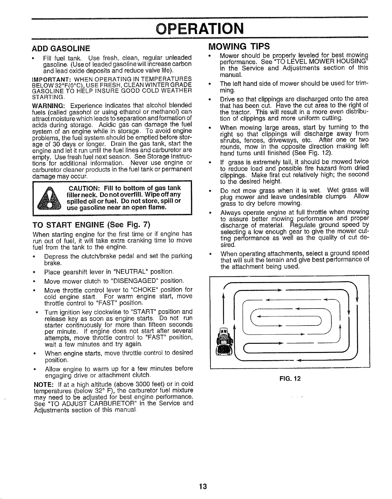
• When mowing large areas, start by turning to the
right so that clippings wilt discharge away from
shrubs, fences, driveways, etc. After one or two
rounds, mow in the opposite direction making left
hand turns until finished (See Fig° 12).
• If grass is extremely tall, it should be mowed twice
to reduce load and possibte fire hazard from dried
clippings_ Make first cut relatively high; the second
to the desired height.
• Do not mow grass when it is weL Wet grass will
plug mower and leave undesirable clumps Allow
grass to dry before mowing,
• Always operate engine at full throttle when mowing
to assure better mowing performance and proper
discharge of material Regutate ground speed by
selecting a low enough gear to give the mower cut-
ting performance as well as the quality of cut de-
sired.
o When operating attachments, select a ground speed
that will suit the terrain and give best performance of
the attachment being used.
f
J
4_
FIG. 12
13
u-
CUSTO RESPONSUBmLJTmES
,uu.............................................. _ ....
FILL IN DATES
AsYooCOMPLETE
....REGULAR SERVICE , _'_.._4_'_"_J#"SERVlCE DATES
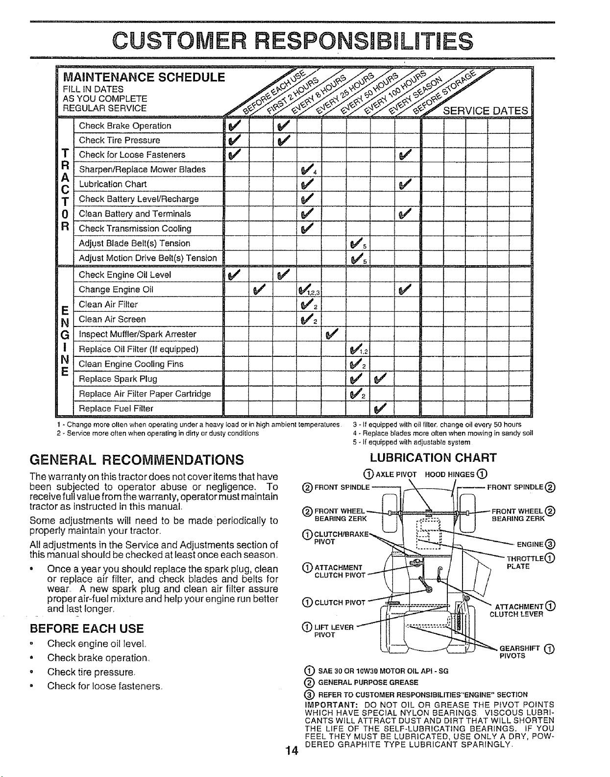
Check Brake Operation _
CheckTire Pressure , , if,,, I_
T Check for Loose Fasteners V"
a ......................
Sharpen/Replace Mower Blades
C Lubrication Chart
T Check Battery Level/Recharge
0 Clean Battery and Terminals
R Check Transmission Cooling
Adjust Blade Belt(s) Tension
Adjust Motion Drive Belt(s) Tension
Check Engine Oil Level
Change Engine Oil
Clean Air Filter
E
N Clean Air Screen
G inspect Muffler/sPark ArreSter
I Repla_ceOil Filter (if equipped)
N Clean Engine Cooling Fins
Replace Spark Plug
v' v'
e,'
v' e/
t
Replace Air Filter Paper Cartridge ..... 6#42
Replace Fuel Filter ........... I ..... ,' '64_ .....
1 - Change more olten when operating under a heavy load or in high ambient temperatures 3 - If equipped with oil It!tar, change oil every 50 hours
2 - Service more otten when operating in dirly or dusty conditions
GENERAL RECOMMENDATIONS
The warranty on this tractor does not cover items that have
been subjected to operator abuse or negligence. To
receive full value from the warranty, operator must maintain
tractor as instructed in this manual.
Some adjustments will need to be madeperiodically to
properly maintain your tractor..
Al! adjustments in the Service and Adjustments section of
this manual should be checked at least once each season.
o Once a year you should replace the spark plug, clean
or replace air filter, and check blades and belts for
wear. A new spark plug and clean air filter assure
proper air-fuel mixture and help your engine run better
and last !onger.
BEFORE EACH USE
, Check engine oil level..
• Check brake operation..
, Check tire pressure.
° Check for loose fasteners.
14
4 _ Replace blades more oiten when mowing in sandy soil
5 - If equipped with adjustable system
LUBRICATION CHART
(3)AXLEP,VOTHOOeHINGES(i:)
@ FRONT WHEEL _ _ FRONT WHEEL @
-- BEARING ZERK 1 14 r _:_::_.
U BEARING ZERK -
7"--
®ATTAO.MENT_ _ j _O_L_
CLUTCH PIVOT ""- __L_ 1,.,_
(_ CLUTCH PIVOT _F.....,_Z_=,,_, ""_" ATTACHMENT (_)
CLUTCH LEVER
P,vo_ [1______ _eEARS.,_®
PIVOTS
(_) SAE 30 OR 10W30 MOTOR OIL API - SG
® GENERAL PURPOSE GREASE
® REFER TO CUSTOMER RESPONSIBiLITtES"ENGtNE" SECTION
IMPORTANT: DO NOT OIL OR GREASE THE PWOT POINTS
WHICH HAVE SPECIAL NYLON BEARINGS VISCOUS LUBRI-
CANTS WILL ATTRACT DUST AND DIRT THAT WILL SHORTEN
THE LIFE OF THE SELF-LUBRICATING BEARINGS, IF YOU
FEEL THEY MUST BE LUBRICATED, USE ONLY A DRY, POW-
DERED GRAPHITE TYPE LUBRICANT SPARINGLY.

i .................... iiiiiiii,, i===1 ........................
RESPONSIBILITIES
i ii1,11111 i iii iiiiiiiiiiiiiiiii
CUSTOMER
,L , ,,i,iii, IIIIII III
TRACTOR
Always observe safety rules when performing any mainte-
nance.
BRAKE OPERATION
If tractor requires more than six (6) feet stopping distance
at high speed in highest gear than brake must be adjusted,
(See "TO ADJUST BRAKE" in the Service and Adjust-
ments section of this manual)..
TIRES
• Maintain proper air pressure in all tires (See "PROD-
UCT SPECIFICATIONS" on page 3 of this manual).,
o Keep tires free of gasoline, oil, or insect control chemi-
cals which can harm rubber.
• Avoid stumps, stones, deep ruts, sharp objects and
other hazards that may cause tire damage..
TO SHARPEN BLADE (See Fig. 14)
Care should be taken to keep the blade batanced_ An
unbalanced blade will cause excessive vibration and even-
tual damage to mower and engine.
• The blade can be sharpened with a file or on a grinding
wheel. Do not attempt to sharpen while on the mower.
= To check blade balance, you will need a 5/8" diameter
steel bolt pin, or a cone balancer. (When using a cone
balancer, follow the instructions suppled with bal-
ancer).
• Slide blade on to an unthreaded portion of the steel bolt
or pin and hold the bolt or pin parallel with the ground,
If blade is balanced, it should remain in a horizontal
position_ If either end of the blade moves downward,
sharpen the heavy end until the blade is balanced.
NOTE: Do not use a nai! for balancing blade. The lobes of
the center hole may appear to be centered, but are not°
BLADE CARE
For best results mower blades must be kept sharp, Re-
place bent or damaged blades..
BLADE REMOVAL (See Fig. 13)
o Raise mower to highest position to allow access to
blades.
• Remove hex bolt, lock washer and flat washer securing
blade°
o Install new or resharpened blade with trailing edge up
towards deck as shown..
• Reassemble hex bolt, lock washer and fiat washer in
exact order as shown°
° Tighten bolt securely (30-35 Ft. Lbs. torque).
IMPORTANT: BLADE BOLT iS GRADE 8 HEAT TREATED
MANDREL
ASSEMBLY
"A GRADE 8 HEAT TREATED BOLT CAN BE IDENTIFIED BY
SIX LINES ON THE BOLT HEAD
FIG. 13
CENTER HOLE
5/8"BOLT
OR PIN
BLADE
FIG. 14
BATTERY (See Fig. 15)
Your tractor has a battery charging system which is suffi-
cient for normal use. However periodic charging of the
battery with an automotive charger will extend its fe.
• Acid solution level in each battery cell should be even
with bottoms of vent wells.. Add only distilled oriron free
water if necessary,, Do not overfill.
. Keep batteryand terminals clean,.
° Keep battery bolts tighL
o Keepvent capstight and small vent holes in caps open.
• Recharge at 6 amperes for 1 hour,,
CUT AWAY VIEW
I IjVENT°AP
WELL
FIG. 15
BATTERY
CELL ACID
LEVEL
15
i= ==,= iii1,,,=
CUSTOMER
TO CLEAN BATTERY AND TERMINALS -
Corrosion and dirt on the battery and terminals can cause
the battery to "leak" power°
, Open battery box door.
• Disconnect BLACK battery cable first then RED bat-
tery cable and remove battery from tractor.
• Wash battery with solution of four tablespoons of
baking sodatoonegallon of water Becareful nottoget
the soda solution into the cells.
- Rinse the battery with plain water and dry,
o Clean terminals and battery cable ends with wire brush
until bright
- Coat terminals with grease or petroleum jeliyo
- Reinstall battery (See "INSTALL BATTERY" in the
Assembly section of this manual).
V- BELTS
Check V-Belts for dete rioration and wear after 100 hours of
operation, Replace if necessary. The belts are not adjust-
able. Replace belts if they begin to slip from wear.
TRANSAXLE COOLING
Keep transaxle free from build_up of dirt and chaff which
can restrict cooling.
RESPONSIBmLITmES
1. , =u uu,uu ........... _ ...................................
Check the crankcase oil leveI before starting the engine
and after each eight (8) hours of continuous use° Tighten
oil fill cap/dipstick securely each time you check the oil
level.
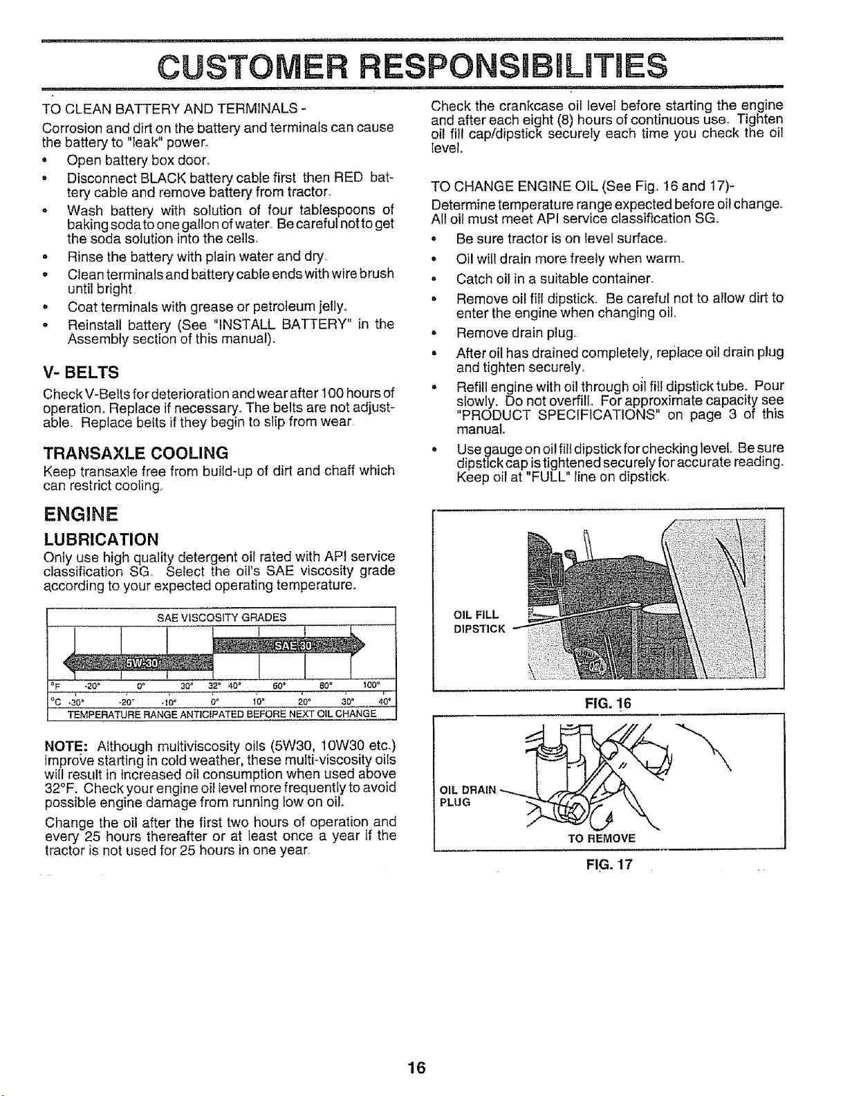
TO CHANGE ENGINE OIL (See Fig. 16 and 17)-
Determine temperature range expected before oi! change.
All oil must meet API service classification SG.
• Be sure tractor is on level surface_
o Oil wilt drain more freely when warm.
- Catch oil in a suitable container.
• Remove oil fill dipstick. Be careful not to allow dirt to
enter the engine when changing oil.
o Remove drain plug,
, After oil has drained completely, replace oil drain plug
and tighten securely,
o Refill engine with oil through oil fill dipstick tube. Pour
slowly. Do not overfill For approximate capacity see
"PRODUCT SPECIFICATIONS" on page 3 of this
manual
° Use gauge on oil fill dipstick for checking level Be sure
dipstick cap is tightened securely for accurate reading.
Keep oil at "FULL" line on dipstick.
ENGINE
LUBRICATION
Only use high quality detergent oil rated with API service
classification SG Select the oil's SAE viscosity grade
according to your expected operating temperature.
SAE VISCOSITY GRADES
• 1
_F -20° 0_ 302 32" 40 _ 60 _ 80 _ _00 _
°c 40° .27_ 4;° co loo 2o° _oo 4oo
TEMPERATURE RANGE ANTICIPATED BEFORE NEXT OIL CHANGE
OIL FILL
DIPSTICK
FIG. 16
NOTE: Although muttiviscosity oils (5W30, 10W30 etc.)
improL,e starting in cold weather, these mufti-viscosity oils
will result in increased oil consumption when used above
32°F. Check your engine oil level more frequently to avoid
possible engine damage from running low on oil.
Change the oil after the first two hours of operation and
every 25 hours thereafter or at least once a year if the
tractor is not used for 25 hours in one year.
PLUG
TO REMOVE
FIG. 17
16
,,,i,i, i,i '"MI'II "11....
CUSTOMER RESPONSIBI
i, i,,i,iii i,ii ii i, ,i iii ,i,,11
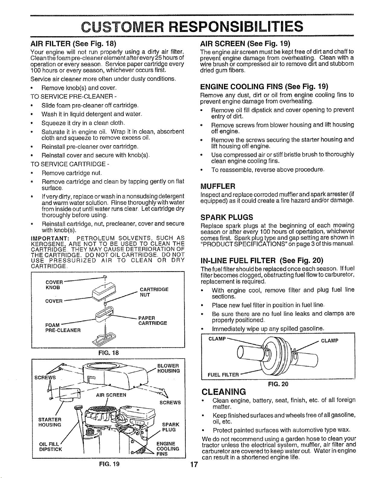
AIR FILTER (See Fig. 18)
Your engine will not run properly using a dirty air filter.
Clean the foam pre-cleaner element after every 25 hours of
operation or every season. Service paper cartridge every
100 hours or every season, whichever occurs first.
Service air cleaner more often under dusty conditions.
. Remove knob(s) and cover+
TO SERVICE PRE-CLEANER -
• SIide foam pre-cleaner off cartridge.
• Wash it in liquid detergent and water+
o Squeeze it dry in a clean cloth.
- Saturate it in engine oil Wrap it in clean, absorbent
cloth and squeeze to remove excess Oito
° Reinstall pre-cteaner over cartridge+
• Reinstall cover and secure with knob(s).
TO SERVICE CARTRIDGE -
- Remove cartridge nut.
o Remove cartridge and clean by tapping gently on flat
surface.
o If very dirty, replace or wash in a nonsudsing detergent
and warm water solution. Rinse thoroughly with water
from inside out until water runs clear. Let cartridge dry
thoroughly before using.
• Reinstall cartridge, nut, precleaner, cover and secure
with knob(s).
IMPORTANT: PETROLEUM SOLVENTS, SUCH AS
KEROSENE, ARE NOT TO BE USED TO CLEAN THE
CARTRIDGE THEY MAY CAUSE DETERIORATION OF
THE CARTRIDGE.. DO NOT OIL CARTRIDGE. DO NOT
USE PRESSURIZED AIR TO CLEAN OR DRY
CARTRIDGE.
COVER
KNOB
CARTRIDGE
NUT
FOAM
PRE+CLEANER
FIG. 18
-,PAPER
CARTRIDGE
SCREWS
STARTER
HOUSING SPARK
PLUG
OIL FILL
DIPSTICK
ENGINE
COOLING
FINS
i iii1,,,
AIR SCREEN (See Fig. 19)
The engine air screen must be kept free of dirt and chaff to
prevent engine damage from overheating., Clean with a
wire brush or compressed air to remove dirt and stubborn
dried gum fibers.
ENGINE COOLING FINS (See Fig. 19)
Remove any dust, dirt or oil from engine cooling fins to
prevent engine damage from overheating+
° Remove oil fill dipstick and cover opening to prevent
entry of dirt.
° Remove screws from blower housing and lift housing
off engine+
• Remove the screws securing the starter housing and
tiff housing off engine+
o Use compressed air or stiff bristle brush to thoroughly
clean engine cooling fins+
° To reassemble, revers°above procedure+
MUFFLER
Inspect and replace corroded muffler and spark arrester (if
equipped) as it could create a fire hazard and/or damage_
SPARK PLUGS
Replace spark plugs at the beginning of each mowing
season or after every 100 hours of opertation, whichever
comes first. Spark plug type and gap setting are shown in
"PRODUCT SPECIFICATIONS" on page 3 of this manual.
IN-LINE FUEL FILTER (See Fig. 20)
The fuel filter should be replaced once each season,, if fuel
fitter becomes clogged, obstructing fuel flow to carburetor,
replacement is required+
° With engine cool, remove filter and plug fuel line
sections°
• Place new fuel filter in position in fuel line_
• Be sure there are no fuel line leaks and clamps are
properly positioned.
Immediatety wipe up any spilted gasoline.
FUEL FILTER _
CLAMP
FIG. 20
CLEANING
e
Clean engine, battery, seat, finish, etc. of all foreign
matter+
- Keep finished surfaces and wheels free of all gasoline,
oil, etc.
• Protect painted surfaces with automotive type wax.
We do not recommend using a garden hose to clean your
tractor unless the electrical system, muffler, air filter and
carburetor are covered to keep water out+ Water in engine
can result in a shortened engine tife_
FIG+ 19 17
,,i ,,,,,,,,,,,,,,i,i ,i.... i ......
SERVICE AN ADJUSTMENTS
CAUTION: BEFORE PERFORMING ANY SERVICE OR ADJUSTMENTS:
o Depress clutch/brake pedal fully and set parking brake.
o Place gearshift lever in"NEUTRAL"position.
• Place attachment clutch in "DISEN(_AGED" position,
o Turn ignition key "OFF" and remove key.
o Make sure the blades and all moving parts have completely stopped.
° Disconnect spark plug wire from spark plug and place wire where it cannot come in contact with
plug.
m
TRACTOR
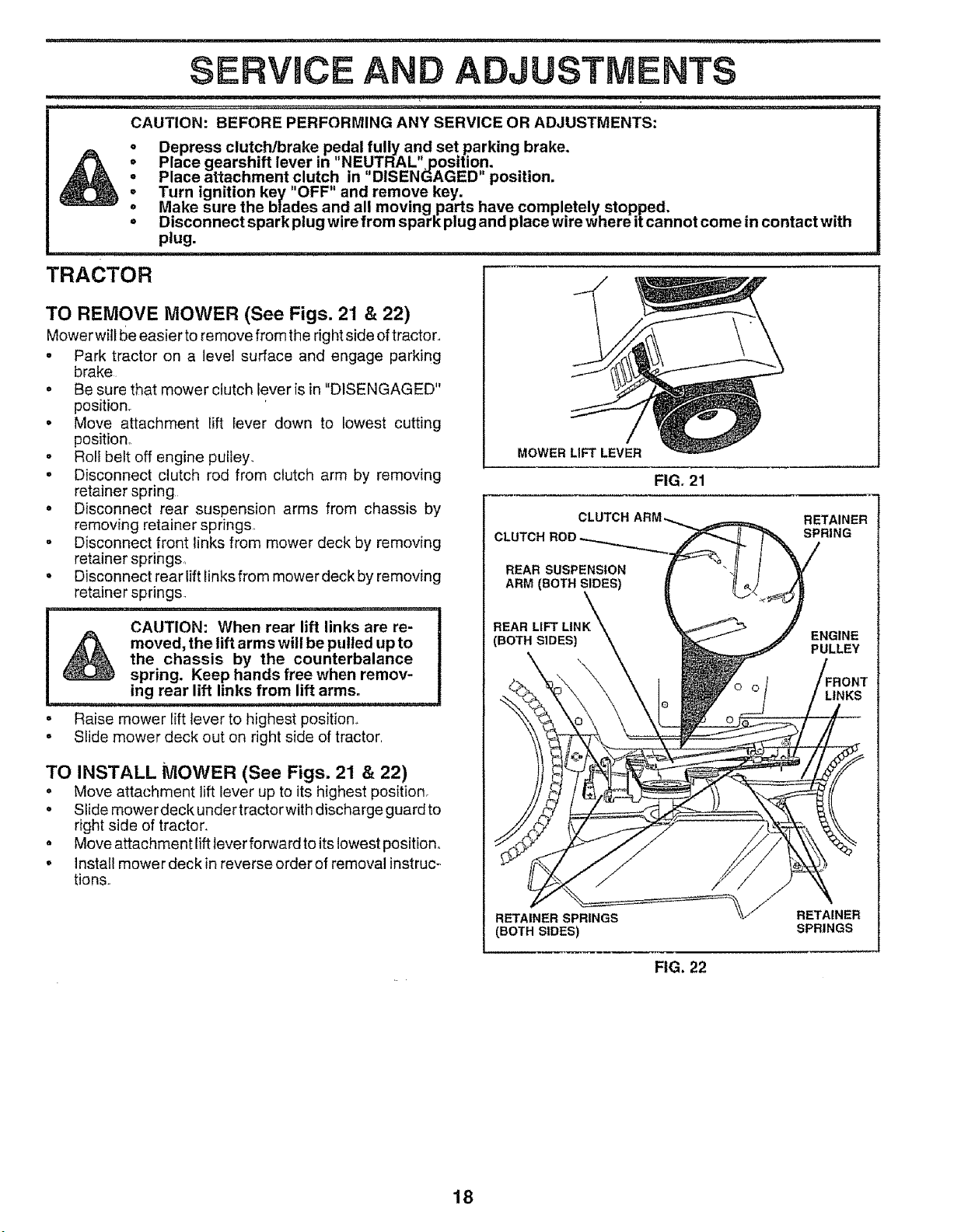
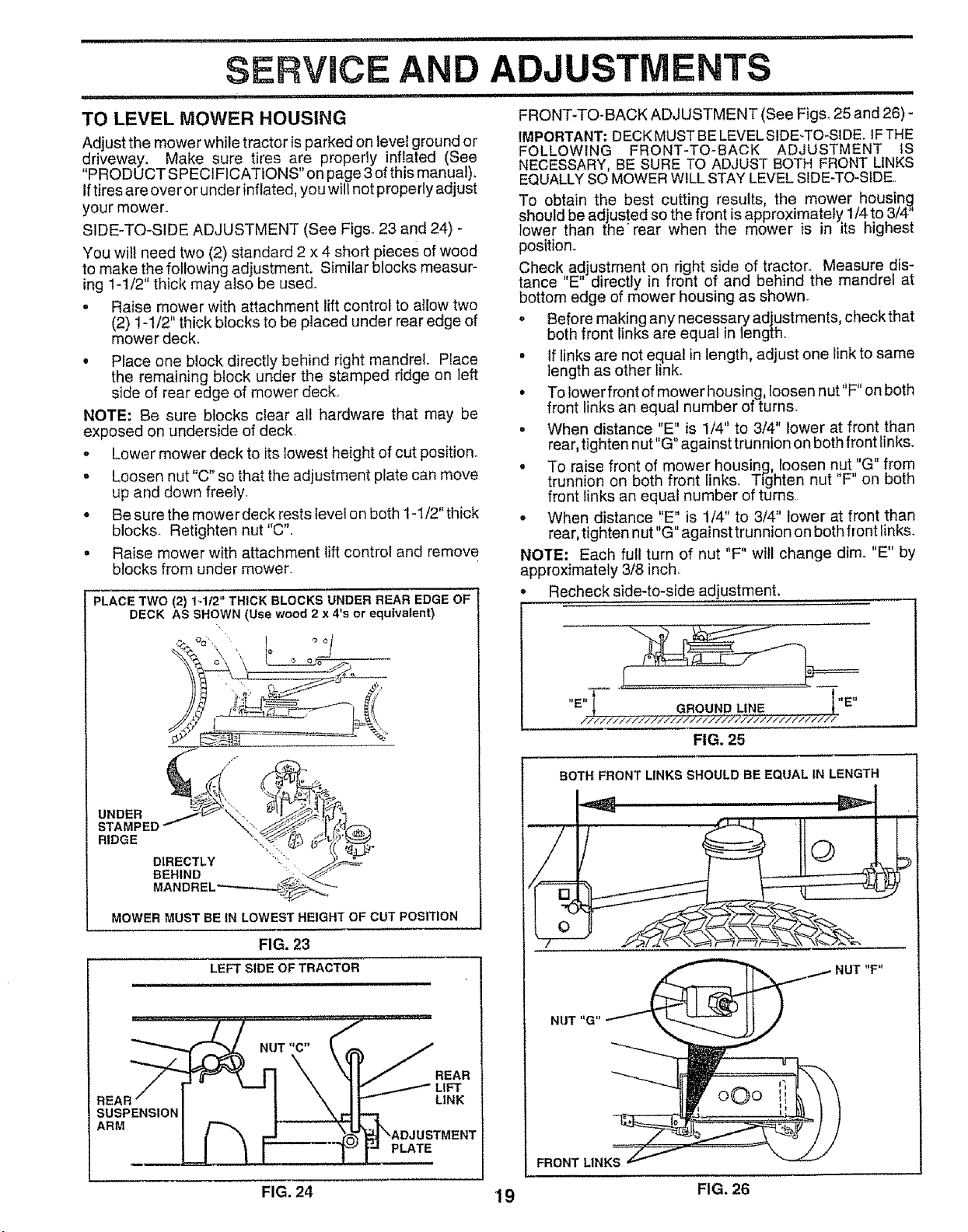
TO REMOVE MOWER (See Figs. 2'1 & 22)
Mower wiil be easier to remove from the right side of tractor.,
• Park tractor on a level surface and engage parking
brake
• Be sure that mower clutch lever is in "DISENGAGED"
position_
• Move attachment lift lever down to lowest cutting
position_
• Roll belt off engine pulley.
• Disconnect clutch rod from clutch arm by removing
retainer spring
• Disconnect rear suspension arms from chassis by
removing retainer springs,
= Disconnect front links from mower deck by removing
retainer springs,
• Disconnect rear lift links from mower deck by removing
retainer springs.
' i, ,,11,,,,,,,,i,
CAUTION: When rear lift links are re-
moved, the lift arms will be pulled up to
the chassis by the counterbalance
spring. Keep hands free when remov-
ing rear lift links from lift arms.
Raise mower lift lever to highest position,,
° Slide mower deck out on right side of tractor,
TO INSTALL MOWER (See Figs. 21 & 22)
• Move attachment lift lever up to its highest position.
• Slide mower deck under tractorwith discharge guard to
right side of tractor.
• Move attachment {iftlever forward to itslowest position°
o Instal! mower deckin reverseorder of removal instruc-
tionso
MOWER LIFT LEVER
FIG. 21
CLUTCH
REAR SUSPENSION
ARM (BOTH SIDES)
RETAINER
SPRING
REAR
(BOTH SIDES)
ENGINE
PULLEY
RETAINER SPRINGS
(BOTH SIDES)
RETAINER
SPRINGS
FIG. 22
18
'=='='"'4 I Nl,='l HINl='ll'HNHN I=11 I"1 IH=N" ='=1
SERVRCE AND ADJUSTMENTS
= , r 'HH '='1 "NIIH'
TO LEVEL MOWER HOUSING
Adjust the mower while tractor is parked on level ground or
driveway, Make sure tires are properly inflated (See
"PRODUCT SPECIFICATIONS" on page 3 of this manual).
Iftires are over or under inflated, you will not properly adjust
your mower.
SIDE-TO-SIDE ADJUSTMENT (See Figs_ 23 and 24) -
You will need two (2) standard 2 x 4 short pieces of wood
to make the following adjustment. Similar blocks measur-
ing 1-1/2" thick may also be used°
= Raise mower with attachment lift control to allow two
(2) 1-1/2" thick blocks to be placed under rear edge of
mower deck_
• Place one block directly behind right mandrel. Place
the remaining block under the stamped ridge on left
side of rear edge of mower deck.
NOTE: Be sure blocks clear al! hardware that may be
exposed on underside of deck
o Lower mower deck to its lowest height of cut position.
° Loosen nut "C" so that the adjustment plate can move
up and down freely.
° Be sure the mower deck rests fevei on both 1-1/2" tlTick
blocks. Retighten nut "C".
° Raise mower with attachment lift control and remove
blocks from under mower.
PLACE TWO (2) 1_112" THICK BLOCKS UNDER REAR EDGE OF
DECK AS SHOWN (Use wood 2 x 4's or equivalent)
<
UNDER
STAI
RIDGE
DIRECTLY
BEHIND
MANDREL
MOWER MUST BE IN LOWEST HEIGHT OF CUT POSITION
FIG. 23
LEFT SIDE OF TRACTOR
SUSPENSION
ARM
REAR
LIFT
LINK
PLATE
= ,H M"H,N'H'= I
FRONT-TO-BACK ADJUSTMENT (See Figs_ 25 and 26) -
IMPORTANT; DECK MUST BE LEVEL SIDE-TO-SIDE. IF THE
FOLLOWING FRONT-TO-SACK ADJUSTMENT tS
NECESSARY, BE SURE TO ADJUST BOTH FRONT LINKS
EQUALLY SO MOWER WILL STAY LEVEL SIDE-TO-SIDE.
To obtain the best cutting results, the mower housing
should be adjusted so the front is approximately 1/4 to 3/4"
lower than the' rear when the mower is in its highest
position°
Check adjustment on right side of tractor. Measure dis-
tance E directly in front of and behind the mandrel at
bottom edge of mower housing as shown+
Before making any necessary adjustments, check that
both front links are equal in length.
° If links are not equal in length, adjust one link to same
length as other link_
° Totowerfront of mowerhousing, loosen nut"F" on both
front links an equal number of turns.
• When distance "E" is 1/4" to 3/4" lower at front than
rear, tighten nut"G" against trunnion on both front links..
o To raise front of mower housing, loosen nut"G" from
trunnion on both front iinks. Tighten nut "F" on both
front links an equal number of turns
• When distance "E" is 1/4" to 3/4" lower at front than
rear, tighten nut "G" against trunnion on both front links.
NOTE: Each full turn of nut "F" will change dim. "E" by
approximately 3/8 inch.
Recheck side-to-side adjustment.
,,=,,t t"E"
'- } GROUND LINE __.__L
lt!T/i_2,1)7<ltl/iltft)/h21"/itlllllliltlll
FIG. 25
/
O
-7"-
BOTH FRONT LINKS SHOULD BE EQUAL IN LENGTH
NUT "G
FRONT LINKS
19
FIG. 24 FIG. 26
j _ ,, uu,lnUUMlUlll,,U,,
SERVICE AND ADJU
....... i,iiiiI imlqr,
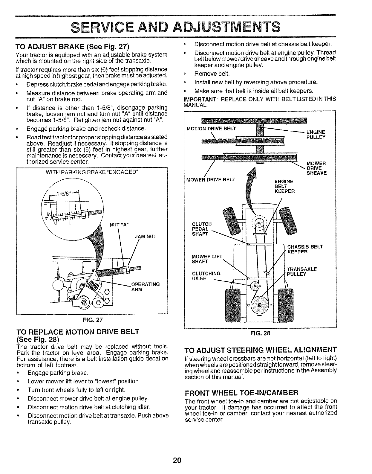
TO ADJUST BRAKE (See Fig. 27)
Your tractor is equippedwith an adjustable brake system
which is mounted on the right side of the transaxle.
If tractor requires more than six (6) feet stopping distance
at high speed in highest gear, then brake must be adjusted°
• Depress clutch/brake pedal and engage parking brake,,
- Measure distance between brake operating arm and
nut "A" on brake rod°
o tf distance is other than 1-5/8", disengage parking
brake, loosen " nut and turn nut "A" until distance
becomes 1-5/8Jam
Retighten jam nut against nut "A".
. Engage parking brake and recheck distance,
o Road test tractor for proper stopping distance as stated
above,_ Readjust if necessary. If stopping distance is
still greater than six (6) feet in highest gear, further
maintenance is necessary. Contact your nearest au-
thorized service center.
WITH PARKING BRAKE "ENGAGED"
NUT "A"
JAM NUT
_OPERATING
ARM
FIG. 27
ENTS
i i ,i iii1,, iiii ........
° Disconnect motion drive belt at chassis belt keeper.
• Disconnect motion drive belt at engine pulley. Thread
belt below mower drive sheave and through engine belt
keeper and engine pulley,
• Remove belt,
. Install new belt by reversing above procedure.
• Make sure that belt is inside all belt keepers,
IMPORTANT: REPLACE ONLY W1TH BELTLISTED IN THIS
MANUAL.
MOTI_ENGIN E
PULLEY
_ MOWER
...........................<-" ."g:vE
MOWER DRIVE BELT ENGINE
BELT
KEEPER
CLUTCH
PEDAL
SHAFT
MOWER LIFT
SHAFT
CLUTCHING
IDLER
O ::]o
CHASSIS BELT
/'KEEPER
TRANSAXLE
PULLEY
==
TO REPLACE MOTION DRIVE BELT
(See Fig. 28)
The tractor drive belt may be replaced without tools,
Park the tractor on level are& Engage parking brake.
For assistance, there is a belt installation guide decal on
bottom of left footrest
o Engage parking brake,
. Lower mower lift lever to "lowest" position,
. Turn front wheels fully to left or right.
. Disconnect mower drive belt at engine pulley.
o Disconnect motion drive belt at clutching idler,
o Disconnect motion drive belt at transaxle, Push above
transaxle pulley.
FIG. 28
TO ADJUST STEERING WHEEL ALIGNMENT
If steering wheel crossbars are not horizontal (left to right)
when wheels are positioned straight forward, remove steer-
ing wheel and reassemble per instructions in the Assembly
section of this manual
FRONT WHEEL TOE-IN/CAMBER
The front wheel toe-in and camber are not adjustable on
your tractor, If damage has occurred to affect the front
wheel toe-in or camber, contact your nearest authorized
service center.
20
SERVHCE AN
= ,,,,1 ,,1 ir 1, i
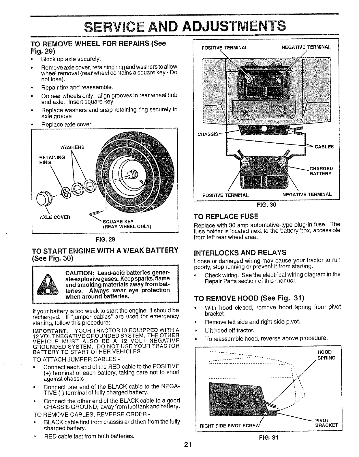
TO REMOVE WHEEL FOR REPAIRS (See
Fig. 29)
o Block up axle securefy.
. Remove axle cover, retaining ring and washersto allow
wheel remova_ (rear wheel contains a square key - Do
not lose)_
• Repair tire and reassemble.,
o On rear wheels only: align grooves in rear wheel hub
and axle. Insert square key.
o Replace washers and snap retaining ring securely in
axle groove,
Replace axle cover.
WASHERS
RETAINING
RING
\
AXLE COVER
I
_SQUARE KEY
(REAR WHEEL ONLY)
FIG. 29
TO START ENGINE WITH A WEAK BATTERY
(See Fig. 30)
11.... 1
i_ CAUTION: Lead-acid batteries gener-
ate explosive gases. Keep sparks, flame
and smoking materials away from bat-
teries. Always wear eye protection
when around batteries.
...................... = ,1111,,,1
If your battery is too weak to start the engine, it should be
recharged. If "jumper cables" are used for emergency
starting, follow this procedure:
IMPORTANT: YOUR TRACTOR IS EQUIPPED WITH A
12 VOLT NEGATIVE GROUNDED SYSTEM. THE OTHER
VEHICLE MUST ALSO BE A 12 VOLT NEGATIVE
GROUNDED SYSTEM. DO NOT USE YOUR TRACTOR
BATTERY TO START OTHER VEHICLES..
TO ATTACH JUMPER CABLES -
• Connect each end of the RED cable to the POSITIVE
(+) terminal of each battery, taking care not to short
against chassis,
• Connect one end of the BLACK cable to the NEGA-
TIVE (-) terminal of fully charged battery,
• Connect the other end of the BLACK cable to a good
CHASSIS GROUND, away from fuel tank and batteryo
TO REMOVE CABLES, REVERSE ORDER
= BLACK cable first from chassis and then from the fully
charged battery
= RED cable last from both batteries.
21
POSITIVE TERMINAL
NEGATIVE TERMINAL
CHARGED
BATTERY
POSITIVE TERMINAL NEGATIVE TERMINAL
FIG. 30
TO REPLACE FUSE
Replace with 30 amp automotive-type plug-in fuse_ The
fuse holder is located next to the battery box, accessible
from left rear wheel area.
INTERLOCKS AND RELAYS
Loose or damaged wiring may cause your tractor to run
poorly, stop running or prevent it from starting°
o Check wiring,, See the electrical wiring diagram in the
Repair Parts section of this manual
TO REMOVE HOOD (See Fig. 31)
o With hood closed, remove hood spring from pivot
bracket,,
. Remove left side and right side pivot,
• Lift hood off tractor.
= To reassemble hood, reverse above procedure.
HOOD
SPRING
RIGHT SIDE PIVOT SCREW
PIVOT
BRACKET
FIG. 31
,,111,1,,,
SERVICE AND ADJUSTMENTS
ij,l_
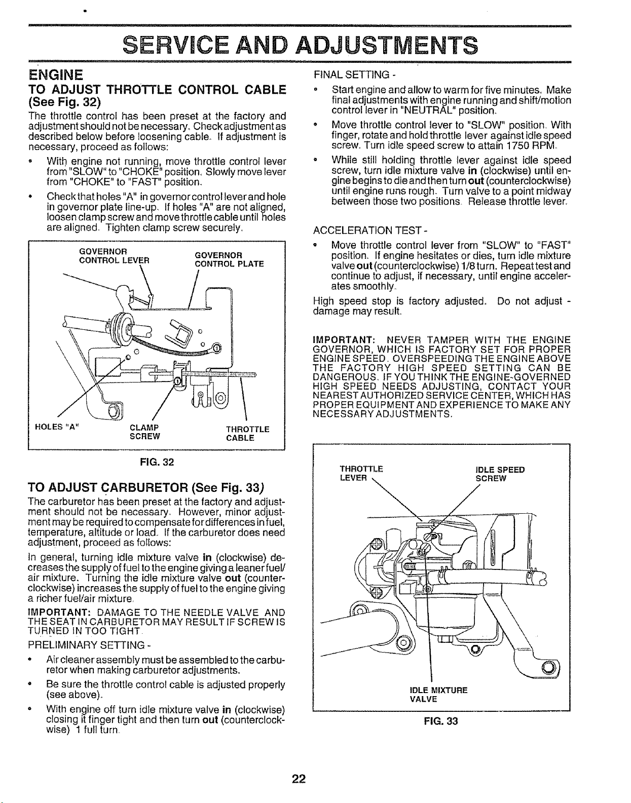
ENGiN E FINALSETTING-
TO ADJUST THRO'i-I'LE CONTROL CABLE "
(See Fig. 32)
The throttle control has been preset at the factory and
adjustment should net be necessary. Checkadjustmentas °
described below before loosening cable. If adjustment is
necessary, proceed as follows:
• With engine not running, move throttle control lever *
from "SLOW" to "CHOKE" position., Slowly move lever
from "CHOKE" to "FAST" position.
. Checkthat holes"A" in governor controltever and hole
in governor plate line-up_ If holes "A" are not aligned,
loosen clamp screw and move throttle cable until holes
are aligned. Tighten clamp screw securely,1
GOVERNOR
CONTROL LEVER
GOVERNOR
CONTROL PLATE
HOLES"A" CLAMP THROTTLE
SCREW CABLE
Start engine and allow to warm for five minutes. Make
final adjustments with engine running and shift/motion
control lever in "NEUTRAL" position..
Move throttle control lever to "SLOW" position. With
finger, rotate and hold throttle lever against idle speed
screw,. Turn idle speed screw to attain 1750 RPM
While still holding throttle lever against idle speed
screw, turn idle mixture valve in (clockwise) until en-
gine begins to die and then turn out (counterclockwise)
until engine runs rough. Turn valve to a point midway
between those two positions Release throttle lever.
ACCELERATION TEST-
- Move throttle control lever from "SLOW" to "FAST"
position.. If engine hesitates or dies, turn idle mixture
valve out (counterclockwise) 1/8turn. Repeattest and
continue to adjust, if necessary, until engine acceler-
ates smoothly.
High speed stop is factory adjusted° Do not adjust -
damage may result..
IMPORTANT: NEVER TAMPER WITH THE ENGINE
GOVERNOR, WHICH IS FACTORY SET FOR PROPER
ENGINE SPEED, OVERSPEEDING THE ENGINE ABOVE
THE FACTORY HIGH SPEED SETTING CAN BE
DANGEROUS, IF YOU THINK THE ENGINE-GOVERNED
HIGH SPEED NEEDS ADJUSTING, CONTACT YOUR
N EAREST AUTHORIZED SERVICE CENTER, WHICH HAS
PROPER EQUIPMENT AND EXPERIENCE TO MAKE ANY
NECESSARY ADJUSTMENTS,
FIG. 32
TO ADJUST CARBURETOR (See Fig. 33)
The carburetor has been preset at the factory and adjust-
ment should not be necessary. However, minor adjust-
ment may be required to compensate for diffe rences in fuel,
temperature, altitude or load. If the carburetor does need
adjustment proceed as foI!ows:
In general, turning idle mixture valve in (clockwise) de-
creases the supply of fuel to the engine giving a leaner fuel/
air mixture. Turning the idle mixture valve out (counter-
clockwise) increases the supply of fuel to the engine giving
a richer fuel/air mixture,
IMPORTANT: DAMAGE TO THE NEEDLE VALVE AND
THE SEAT IN CARBURETOR MAY RESULT IF SCREW IS
TURNED IN TOO TIGHT.
PRELIMINARY SETTING -
° Air cleaner assembly must be assembled to the carbu-
retor when making carburetor adjustments°
• Be sure the throttle control cable is adjusted properly
(see above).
. With engine off turn idle mixture valve in (clockwise)
closing itfinger tight and then turn out (counterclock-
wise) 1 fult turn.
THROTTLE IDLE SPEED
LEVER_ _z_SCREW
IDLE MIXTURE
VALVE
FIG. 33
22
i
STORAGE
, iiiii1,1..... i1,,,1111111 iiiii U,Ul ii,
Immediately prepare your tractor for storage at the end of ENGINE
the season or if the tractor will not be used for 30 days or
more.
i ii u ""UlIMU ''"'11 "U' It"'
III
CAUTION: Never store the tractor with
gasoline in the tank inside a building
where fumes may reach an open flame
or spark. Allow the engine to cool
before storing in any enclosure.
TRACTOR
Remove mower from tractor for winter storage. When
mower is to be stored for a period of time, clean it thor-
oughly, remove all dirt, grease, leaves, etc. Store in a
clean, dry area.
• Clean entire tractor (See"CLEANING"in the Customer
Responsibilities section of this manual).
• Inspect and replace belts, if necessary (See belt re-
placement instructions in the Service and Adjustments
section of this manual).
o Lubricate as shown in the Customer Responsibilities
section of this manual.
,, Be sure that all nuts, bolts and screws are securely
fastened.. Inspect moving parts for damage, breakage
and wear. Replace if necessary_
• Touch up all rusted or chipped paint surfaces; sand
lightiy before painting.
BATTERY
o Fully charge the battery for storage.
• After a period of time in storage, battery may require
recharging.
o To help prevent corrosion and power leakage during
long periods of storage, battery cables should be
disconnected and battery cleaned thoroughly (see "TO
CLEAN BATTERY AND TERMINALS" in the Cus*
tomer Responsibilities section of this manual)..
o After cleaning, leave cables disconnected and place
cables where they cannot come in contact with batter,/
terminals°
= Be sure battery drain tube is securely attached.
FUEL SYSTEM
IMPORTANT: IT IS IMPORTANT TO PREVENT GUM
DEPOSITS FROM FORMING IN ESSENTIAL FUEL
SYSTEM PARTS SUCH AS CARBURETOR, FUEL FtLTER,
FUEL HOSE, OR TANK DURING STORAGE, ALSO,
EXPERIENCE INDICATES THAT ALCOHOL BLENDED
FUELS (CALLED GASOHOL OR USING ETHANOL OR
METHANOL) CAN ATTRACT MOISTURE WHICH LEADS
TO SEPARATION AND FORMATION OF ACIDS DURING
STORAGE° ACIDIC GAS CAN DAMAGE THE FUEL
SYSTEM OF AN ENGINE WHILE IN STORAGE.
o Drain the fuel tank°
• Start the engine and let it run until the fuel lines and
carburetor are empty.
. Never use engine or carburetorcleaner products in the
fuel tank or permanent damage may occur.
• Use fresh fuel next season.
NOTE: Fuel stabilizer is an acceptable alternative in
minimizing the formation of fuel gum deposits during stor-
age, Add stabilizer to gaso{ine in fuel tank or storage
container. Always follow the mix ratio found on stabilizer
container. Run engine at least 10 minutes after adding
stabilizer to allow the stabilizer to reach the carburetor. Do
not drain the gas tank and carburetor if using fuel stabilizer.
ENGINE OIL
Drain oi! (with engine,warm) and replace with clean engine
oil.. (See ENGINE in the Customer Responsibilities
section of this manual)..
CYLINDERS
* Remove spark plug(s),.
. Pour one ounce of oil through spark plug hole(s) into
cylinder(s)_
o Turn ignition key to "START" position for a few seconds
to distribute oil..
o Replace with new spark plug(s).
OTHER
° Do not store gasoline from one season to another.
. Replace your gasoline can if your can starts to rust.
Rust and/or dirt in your gasoline will cause problems.
. If possible, store your tractor indoors and cover it to
give protection from dust and dirt..
° Cover your tractor with a suitable protective cover that
does not retain moisture_ Do not use plastic. Plastic
cannot breathe which atiows condensation to form and
will cause your tractor to rust°
IMPORTANT: NEVER COVER TRACTOR WHILE ENGINE
AND EXHAUST AREAS ARE STILL WARM
23

L i 111111.............................................. i1,,11, i,iii, ,i , HI'II'II'"'I" '1' II III1' IIII
TROUBLESHOOTING POINTS
...... _ i i1,11
PROBt.EM CAUSE CORRECTION
Will not start
Hard to start
"I,"MH
Engine will not turn over
i, ' i .....................
Engine clicks but will not
start
Loss of power
i1,1=1I,IMIM,,,,II I I
Excessive vibration
1_ Out of fuel,
2 Engine not "CHOKED" propedy,
3, Engine flooded
4. Bad spark plug
5 Dirty air filter
6. Dirty fuel filter.
7 Water in fuel
9
!0
Loose or damaged wIdng
Carburetor out of adjustment.
Engine valves out of adjustment.
I Dirty air filter
2 Bad spark plug
3 Weak or dead battery.
4 Dirty fuel filter.
5 Stale or dirty fuel
6 Loose or damaged wiring.
7 Carburetor out of adjustment
8 Engine valves out of adjustment.
1. Clutch/brake pedat not depressed.
2. Attachment clutch is engaged.
3 Weak or dead battery.
4 Blown fuse
5 Corroded battery terminals
6 Loose or damaged widng
7. Faulty ignition switch.
8. Faulty solenoid or starter.
9 Faulty operator presence switch(es).
1 Weak or dead battery_
2 Corroded battery terminals
3 Loose or damaged wtdng
4. Faulty solenoid or starter.
1 Cutting too much grass/too fast
2 Thmttie In "CHOKE" position
3 Build-up of grass, teaves and Irash under mower
4. Dirty air filter
5 Low oil levelldirty oil
6 Faulty spark plug.
7 Dirty fuel fiiter
8 Stale or dirty fuel
9 Water In fuel
10. Spark plug wire loose
t Dirty engine air screen/fins
12 Dirty/clogged muffler
13 Loose or damaged wiring..
14 Carburetor out of adjustment.
15. Engine valves out of adjustment.
1 Worn, benl or loose blade
2, Bent blade mandrel
3 Loose/damaged part(s)
t Fitl fuet tank
2. See "TO START ENGINE" in Operation section.
3 Wait several minutes before attempting to start.
4. Replace spark plug_
5. Clean/replace air filter.
6. Replace fuel filter.
7. Drain fuel tank and carburetor, refill tank with fresh
gasoline and replace fuel filter
8. Check all wiring.
9 Conlact an authorized service center/department.
t O, Contact an authorized service centerldepartment.
1. Clean/replace air filter
2 Replace spark plug
3 Recharge or replace battery
4. Replace fuel filter.
5. Drain fuel tank and refill with fresh gasoline
6. Check all wiring
7 Contact an authorized service center/department
8.. Contact an authorized service center/department.
1 Depress clutch/brake pedal°
2. Disengage attachment clutch.
3 Recharge or replace battery
4 Replace fuse.
5 Ciean battery terminals
6 Check all wiring
7 Check/replace ignition switch.1
8 ChscWreplace solenoid or starter
9 Contact an authorized service center/department
1 Recharge or rep{ace battery
2 Clean battery terminals
3. Check all wiring
4 Check/replace solenoid or starter
1 Set in "H_gher Cut" poslt{on/_'educe speed
2. Adjust throttle control..
3 Clean underside of mower housing.
4 Clear#replace air filter
5 Check oil level/change oil
6 Clean and regap or change spark prug.
7. Replace fuel filter
8 Drain fuel tank and refill with fresh gasoline
9 Drain fuel tank and carburetor, refill tank with fresh
gasoline and replace fuel filter
10 Connect and tighten spark plug wire
11 CIean engine air screen/fins.
12 Clean/replace muffler
13 Check all wiring
14 Contact an authorized service center/department
15 Contact an authorized service center/department
1 Replace blade. Tighten blade bolt.
2. Replace blade mandrel
3. Tighten loose part(s) Replace damaged parts.
24

LJ
Engine continues to run
when operator leaves seat
with attachment clutch
engaged
i
Poor cut - uneven
Mower blades will not
rotate
ii
Poor grass discharge
Headlight(s) not working
(if so equipp_.d)
Battery will not charge
Engine "backfires"
when turning engine
"OFF"
CAUSE
ii i i i iiii1,1
1 Faulty operator-safety presence controI system.
t Worn, bent or loose blade
2, Mower deck not level,
3 Buildup of grass, Ieaves, and trash under mower
4 Bent blade mandrel
5 CIogged mower deck vent holes from buiIdup of
grass, leaves, and trash around mandrels
1 Obstruction In clutch mechanism,.
2. Worr_damaged mower drive heir.
3, Frozen Idler pulley
4 Frozen b_ade mandrel
1 Engine speed too stow
2 Travel speed too fast
3 Wet grass,,
4 Mower deck not level,,
5 Low/uneven tire air pressure
6 Worn, bent or loose blade
7 Buildup of grass, leaves and trash under mower_
8 Mower drive belt worn,
g. Blades Improperly Installed
I0 Improper blades used.
11 Clogged mower deck vent holes from butldup of
grass, leaves, and trash around mandrels
!. Switch is "OFF"
2 Bulb(s) burned out
3, Faulty light SWitChr
4. Loose or damaged wiring
5., BIown fuse
1 Bad battery ceU(s)
2 Poor cable connections,
3 Faulty regulator (if so equipped)
4, Faully alternator.
i n ,11,,i iii1,,11,
Engine throttle control not set at "SLOW"
position for 30 seconds before stopping engine
CORRECTION
1 Check wiring, switches and connections. If not
corrected, contact an authorized service cented
department
t Replace blade Tighten blade bolt
2 Level mower deck,
3 Clean underside of mower housing
4.. Replace blade mandrel.
5, Clean around mandrels to open vent holes,
1 Remove obstruction
2, Replace mower drive belt.
3. Replace Idler pulley,
4. Rep{ace blade mandrel..
t Place throttle control in "FAST" position
2 Shift to sfower speed.
3 Allow grass to dry before mowing
4 Level mower deck
5 Checkttres for proper air pressure
6. Replace/sharpen blade. Tighten blade bolt
7. Clean underside of mower housing
8 Replace mower drive belt,
9 Reinstall blades sharp edge down
10 Replace with blades listed _nthis manual
1t. Ciean around mandrels to open vent holes
1 Turn switch "ON".
2 Replace bulb(s)
3, Check/replace light switch
4 Check wIdng and connections
5 Replace fuse
1. Replace battery.
2. Check/clean a[I connections.
3. Replace regulator
4 Replace alternator
1 Move throttle control to "SLOW" position and alIow
to idle for 30 seconds before stopping engine
25
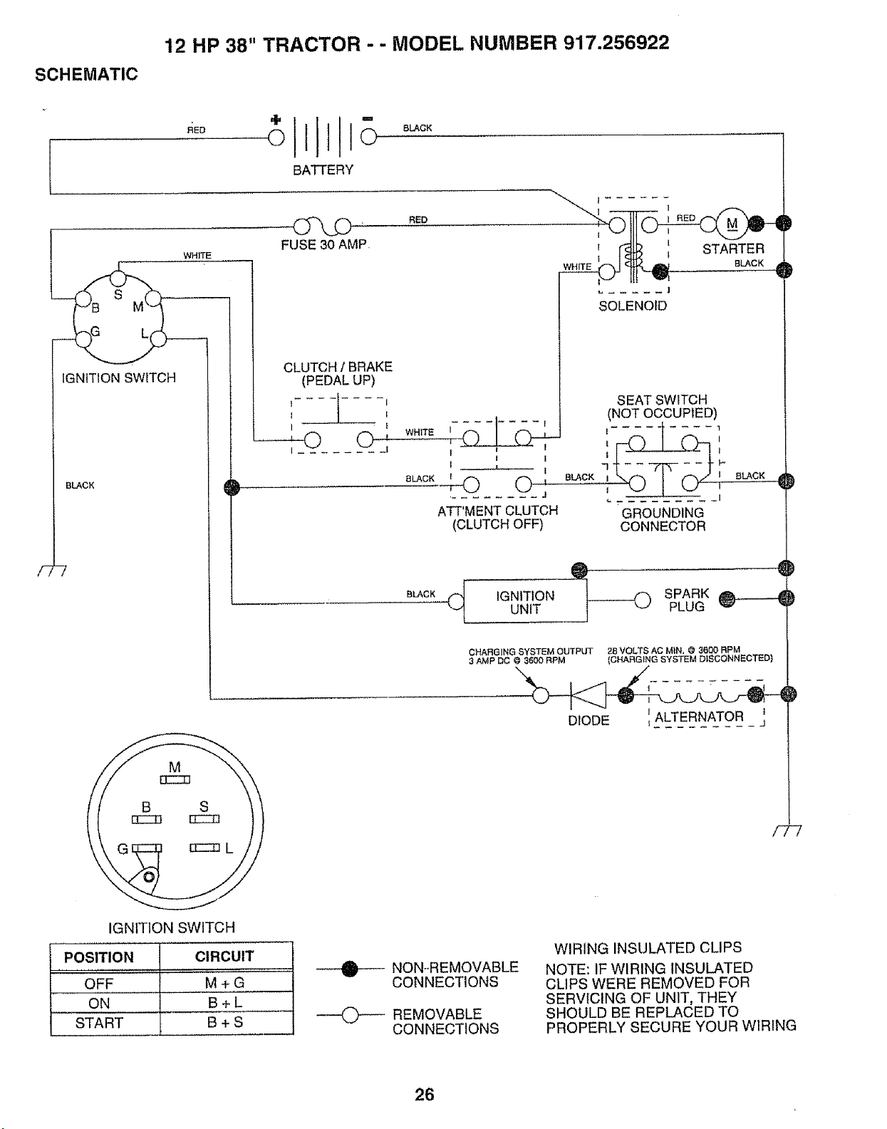
SCHEMATIC
12 HP 38" TRACTOR - - MODEL NUMBER 917.256922
÷
,4Eo O
IGNITION SWITCH
BLACK
/77
IGNITION SWITCH
POSITION CIRCUIT
................... i '"', .... '"'
OFF M + G
ON B+L
START B + S
)
I ......
; r_ : STARTE_-/ R
I- Ifi -- .
BATTERY
FUSE 30 AMP.
CLUTCH 1BRAKE
(PEDAL UP)
tt.... _----Ii
C>'-
BLACK
RED
]
SOLENOID
SEAT SWITCH
WHITE i........ i
I
1 .... t I
I
BLACK i 0 0 '
J
A'FT'MENTCLUTCH
(CLUTCH OFF)
(NOT OCCUPIED)
8LACK I I 8_CK d
I I
GROUNDING
CONNECTOR
BLACK
IGNITION SPARK______}UNIT PLUG
CHARGING SYSTEM OUTPUT 28 VOLTS AC M_N.@ 3600 RPM
3 AMP OC @ 3600 RPM (CHARGING SYSTEM D_SCONNECTED)
F
DIODE
NON-REMOVABLE
CONNECTIONS
----0--" REMOVABLE
CONNECTIONS
WIRING INSULATED CLIPS
NOTE: IF WIRING INSULATED
CLIPS WERE REMOVED FOR
SERVICING OF UNIT, THEY
SHOULD BE REPLACED TO
PROPERLY SECURE YOUR WIRING
26
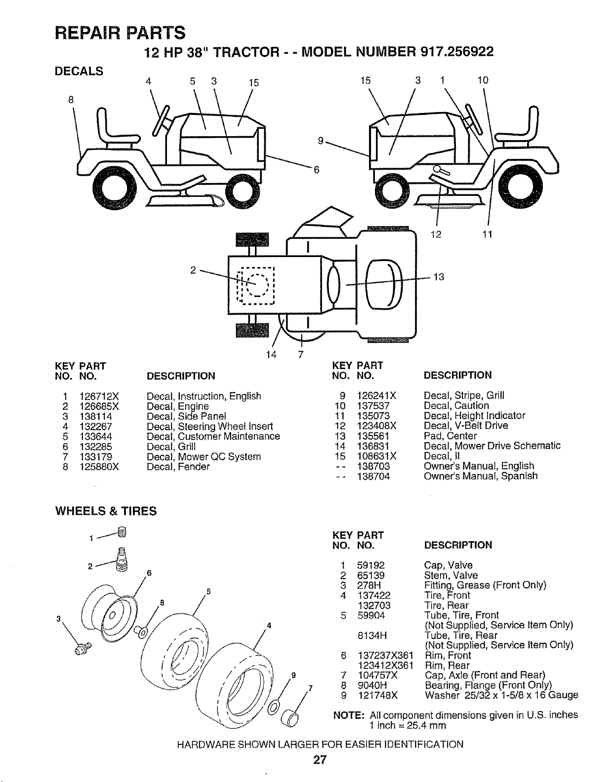
REPAIR PARTS
12 HP 38" TRACTOR - - MODEL NUMBER 917.256922
DECALS
4 5 3 I5 15 3 1 10
12 11
13
14 7
KEY PART KEY PART
NO. NO. DESCRIPTION NO. NO. DESCRIPTION
1 126712X Decal, Instruction, English 9 126241X
2 126685X Decal, Engine 10 137537
3 138114 Decal, Side Panel 11 135073
4 132267 Decal, Steering Wheel Insert 12 123408X
5 133644 Decal, Customer Maintenance 13 135561
6 132285 Decal, Grill 14 136831
7 133179 Decal, Mower QC System 15 t08631X
8 125880X Decal, Fender - - 138703
- - 138704
Decal, Stripe, Grill
Decal, Caution
Decal, Height Indicator
Decal, V-Belt Drive
Pad, Center
Decal, Mower Drive Schematic
Decal, I1
Owner's Manual, English
Owner's Manual, Spanish
WHEELS & TIRES
KEY PART
NO. NO. DESCRIPTION
9
7
1
2
3
4
7
8
9
59192
65139
278H
137422
132703
59904
8134H
137237X361
123412X361
104757X
9040H
121748X
Cap, Valve
Stem, Valve
Fitting, Grease (Front Only)
Tire, Front
Tire, Rear
Tube, Tire, Front
(Not Supplied, Service Item Only)
Tube, Tire, Rear
(Not Supplied, Service Item Only)
Rim, Front
Rim, Rear
Cap, Axle (Front and Rear)
Bearing, Flange (Front Only)
Washer 25/32 x 1-5/8 x 16 Gauge
NOTE: All component dimensions given in U.S. inches
1 inch = 25.4 mm
HARDWARE SHOWN LARGER FOR EASIER IDENTIFICATION
27
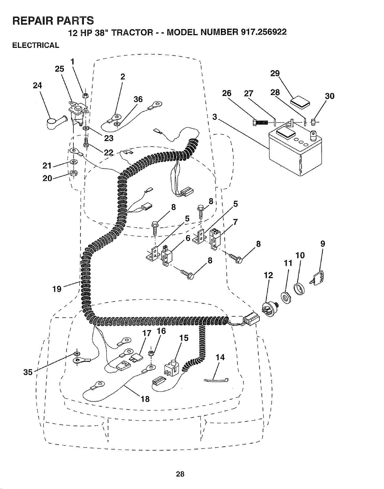
REPAIR PARTS
12 HP 38" TRACTOR - - MODEL NUMBER 917.256922
ELECTRICAL
24
35
21
_ 23
l
1
1
/
19
2
36
\
26
27
8
9
12
18
15
i I
l/
\
\
14
\
/
J
t
28
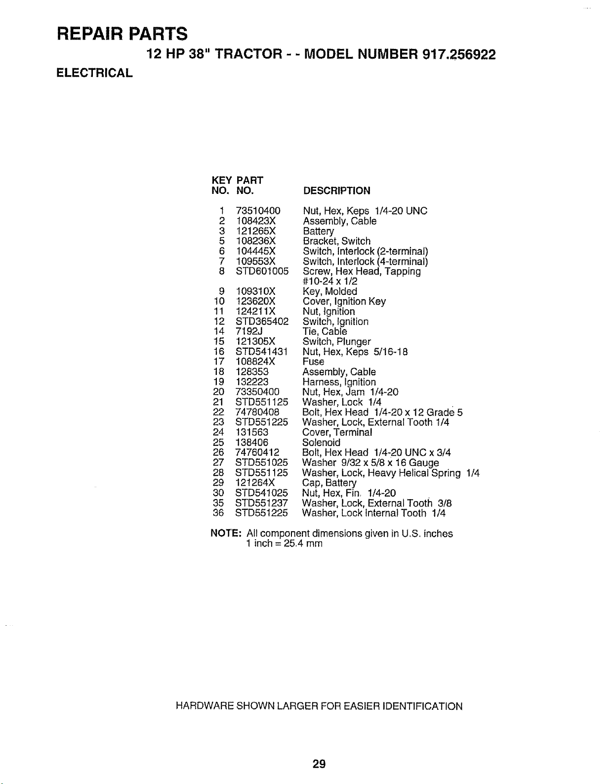
REPAIR PARTS
12 HP 38" TRACTOR - - MODEL NUMBER 917.256922
ELECTRICAL
KEY PART
NO, NO, DESCRIPTION
1 73510400
2 108423X
3 121265X
5 108236X
6 104445X
7 !09553X
8 STD60'1005
9 1093t0X
10 123620X
11 1242IIX
12 STD365402
14 7192J
t5 121305X
16 STD541431
17 108824X
18 128353
19 132223
20 73350400
21 STD551125
22 747804O8
23 STD551225
24 131563
25 138406
26 74760412
27 STD551025
28 STD551125
29 121264X
30 STD54t025
35 STD55t237
36 STD551225
Nut, Hex, Keps 1/4-20 UNC
Assembly, Cable
Battery
Bracket, Switch
Switch, interlock (2-terminal)
Switch, Interlock (44erminal)
Screw, Hex Head, Tapping
#!0-24 x 1/2
Key, Molded
Cover, Ignition Key
Nut, Ignition
Switch, Ignition
Tie, Cable
Switch, Plunger
Nut, Hex, Keps 5/!6-18
Fuse
Assembly, Cable
Harness, Ignition
Nut, Hex, Jam 1/4-20
Washer, Lock 1/4
Bolt, Hex Head 1/4-20 x 12 Grade 5
Washer, Lock, External Tooth 1/4
Cover, Terminal
Solenoid
Bolt, Hex Head 1/4-20 UNC x 3/4
Washer 9/32 x 5/8 x 16 Gauge
Washer, Lock, Heavy Helical Spring 1/4
Cap, Battery
Nut, Hex, Fin, 1/4-20
Washer, Lock, External Tooth 3/8
Washer, Lock internal Tooth 1/4
NOTE: All component dimensions given in U.S. inches
1 inch = 25.4 mm
HARDWARE SHOWN LARGER FOR EASIER IDENTIFICATION
29
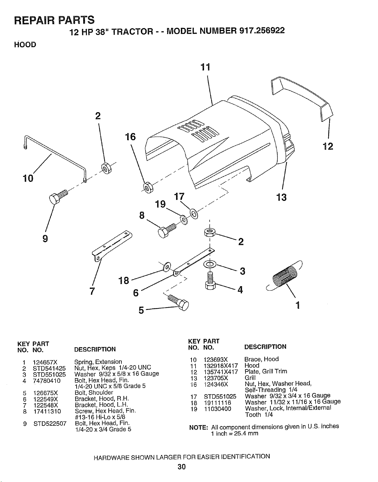
REPAIR PARTS
12 HP 38" TRACTOR - - MODEL NUMBER 917.256922
HOOD
11
/
10
J
9
\
1
12
KEY PART
NO. NO.
1
2
3
4
5
6
7
8
124657X
STD541425
STD551025
74780410
I26675X
122549X
122548X
17411310
STD522507
DESCRIPTION
Spring, Extension
Nut, Hex, Keps 1/4-20 UNC
Washer 9/32 x 5/8 x 16 Gauge
Bolt, Hex Head, Fin.
1/4-20 UNC x 5/8 Grade 5
Bolt, Shoulder
Bracket, Hood, RH..
Bracket, Hood, LH.
Screw, Hex Head, Fin.
#13-t6 Hi-Lo x 5/8
Bolt, Hex Head, Fin.
1/4-20 x 3/4 Grade 5
KEY PART
NO, NO. DESCRIPTION
10 123693X Brace, Hood
11 132918X417 Hood
12 13574IX417 Plate, Grill Trim
13 123705X Grill
16 t24346X Nut, Hex, Washer Head,
Self-Threading 1/4
t7 STD551025 Washer 9/32 x 3/4 x 16 Gauge
18 19111116 Washer 11/32 x11/16 x16 Gauge
19 11030400 Washer, Lock, Internal/Externa!
Tooth 1/4
NOTE: All component dimensions given in U.S_ inches
1 inch = 25.4 mm
HARDWARE SHOWN LARGER FOR EASIER IDENTIFICATION
30
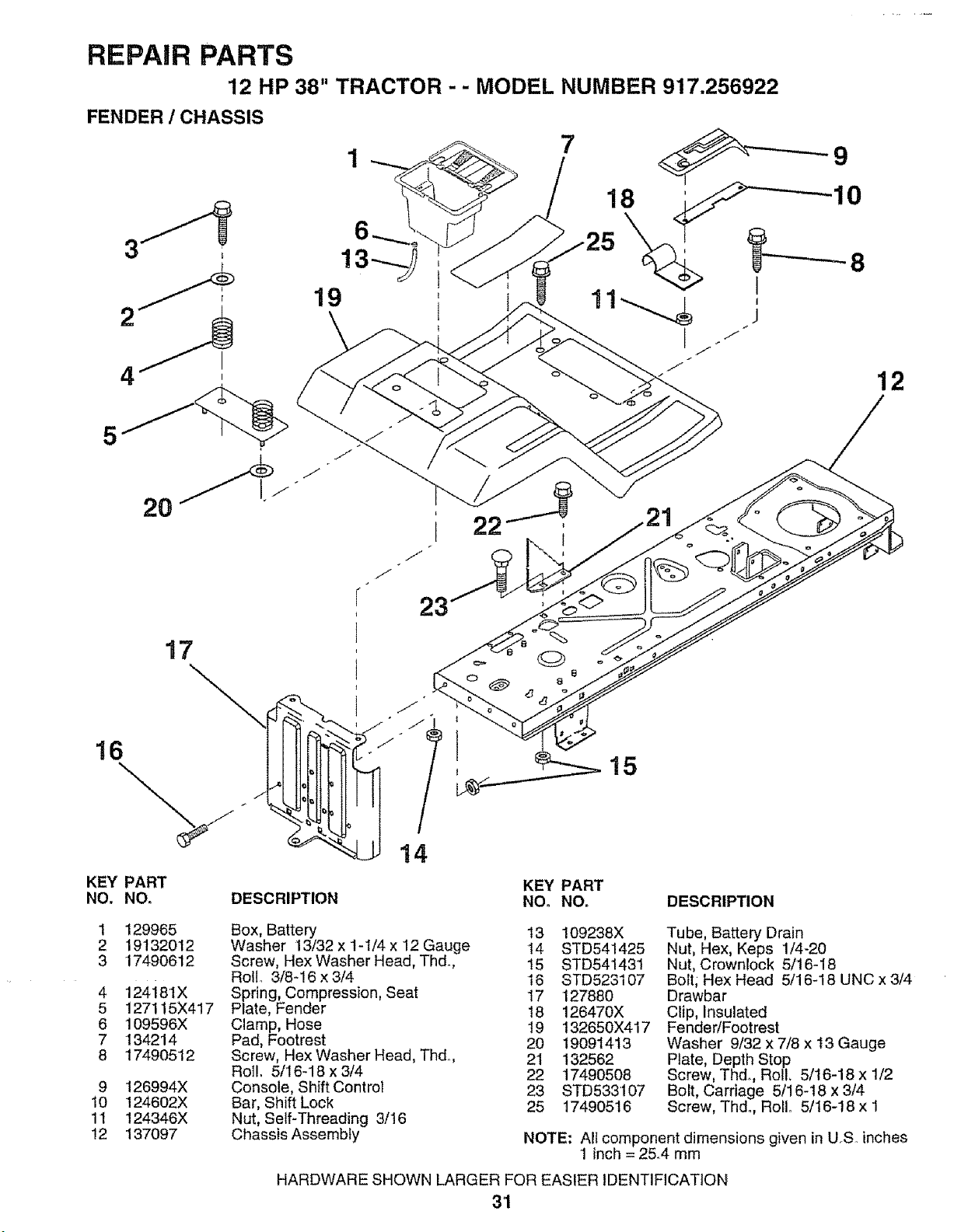
REPAIR PARTS
12 HP 38" TRACTOR - - MODEL NUMBER 917.256922
FENDER / CHASSIS
4
I
I
12
5
17
KEY PART
NO, NO.
23
14
KEY PART
DESCRIPTION NO. NO. DESCRIPTION
1
2
3
4
5
6
7
8
9
10
11
12
129965
19132012
17490612
124i8IX
127115X417
109596X
134214
17490512
126994X
124602X
124346X
137097
Box, Battery 13 109238X
Washer 13/32 x 1-1/4 x 12 Gauge 14 STD541425
Screw, Hex Washer Head, Thd. !5 STD541431
Roll, 3/8-!6x3/4 16 STD523107
Spring, Compression, Seat 17 127880
Plate, Fender 18 126470X
Clamp, Hose 19 132650X417
Pad, Footrest 20 t9091413
Screw, Hex Washer Head, Thd,, 21 132562
Rol!, 5/16-18 x 3/4 22 17490508
Console, Shift Control 23 STD533107
Bar, Shift Lock 25 17490516
Nut, Self-Threading 3/16
Chassis Assembly
Tube, Battery Drain
Nut, Hex, Keps 1/4-20
Nut, Crownlock 5/16-18
Bolt; Hex Head 5/16-18 UNC x 3/4
Drawbar
Clip, Insulated
Fender/Footrest
Washer 9/32 x 7/8 x 13 Gauge
Plate, Depth Stop
Screw, Thd. Roll, 5/16-18 x 1/2
Bolt, Carriage 5/16-18 x 3/4
Screw, Thdo, RolL 5/t6-18 x 1
NOTE: All component dimensions given in U.S. inches
1 inch = 2&4 mm
HARDWARE SHOWN LARGER FOR EASIER IDENTIFICATION
31
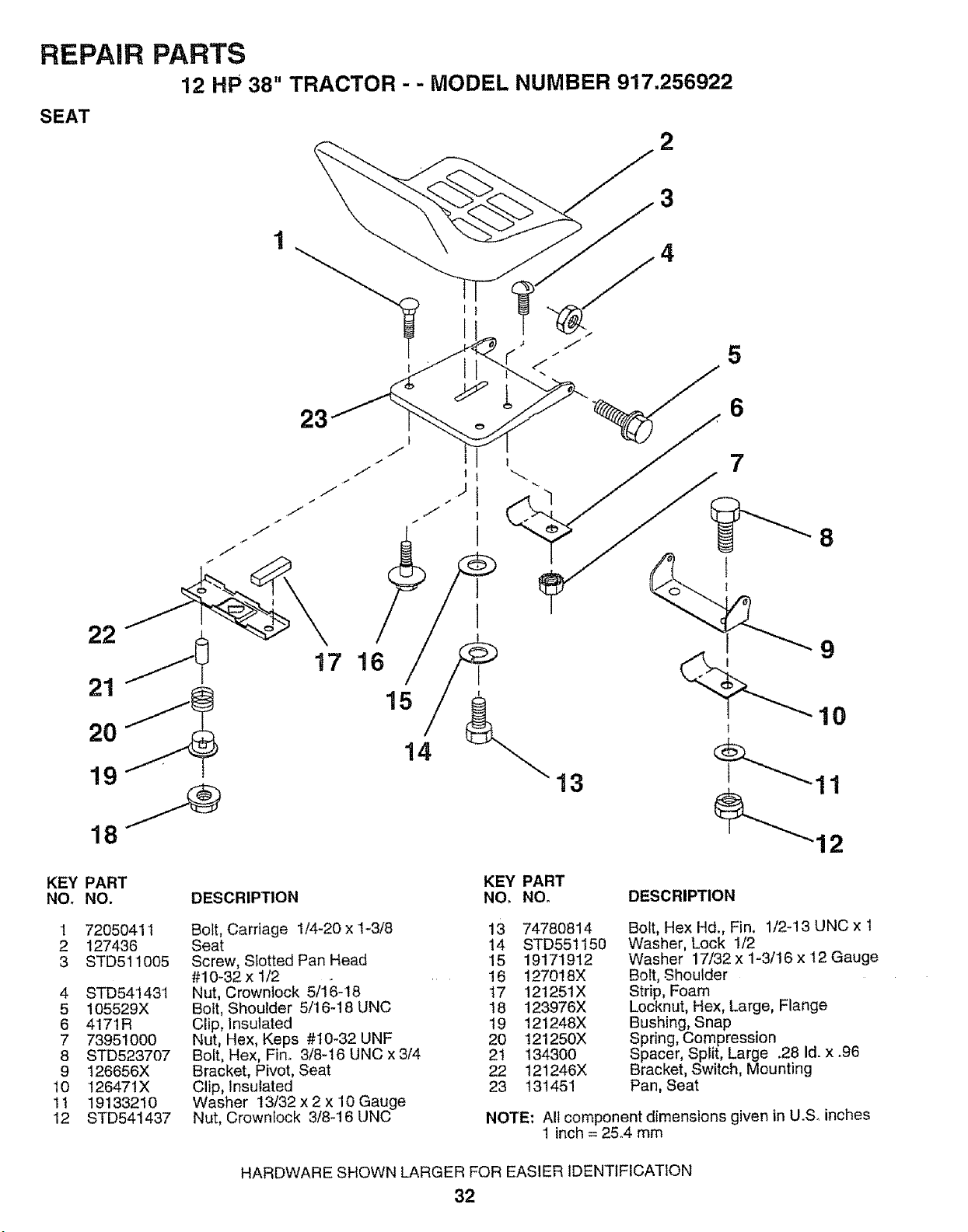
REPAIR PARTS
12 HP 38" TRACTOR - - MODEL NUMBER 917.256922
SEAT
2
3
4
5
J
22
21
20
19
17 16
15
14
KEY PART
NO. NO.
1 72050411
2 127436
3 STD511005
4 STD541431
5 105529X
6 4171R
7 73951000
8 STD523707
9 126656X
10 126471X
11 19133210
12 STD541437
KEY PART
DESCRIPTION NO, NO.
Bolt, Carriage 1/4-20 x 1-3/8 13
Seat 14
Screw, Slotted Pan Head 15
#10-32 x t/2 16
Nut, Crownlock 5/16-18 17
Bolt, Shoulder 5/'16-18 UNC 18
Clip, Insulated 19
Nut, Hex, Keps #10-32 UNF 20
Bolt, Hex, Fin.. 3/8-16 UNC x 3/4 2t
Bracket, Pivot, Seat 22
Clip, Insulated 23
Washer 13/32 x 2 x 10 Gauge
Nut, Crownlock 3/8-16 UNC
6
' 7
8
t
13
12
74780814
STD551150
19171912
!27018X
121251X
123976X
121248X
t21250X
134300
121246X
131451
DESCRIPTION
Bolt, Hex Hd., Fin. 1/2-13 UNC x t
Washer, Lock 1/2
Washer 17/32 x 1-3/16 x 12 Gauge
Bolt, Shoulder
Strip, Foam
Locknut, Hex, Large, Flange
Bushing, Snap
Spring, Compression
Spacer, Split, Large .28 Id. x °96
Bracket, Switch, Mounting
Pan, Seat
NOTE: All component dimensions given in U.S. inches
1 inch = 25°4 mm
HARDWARE SHOWN LARGER FOR EASIER IDENTIFICATION
32
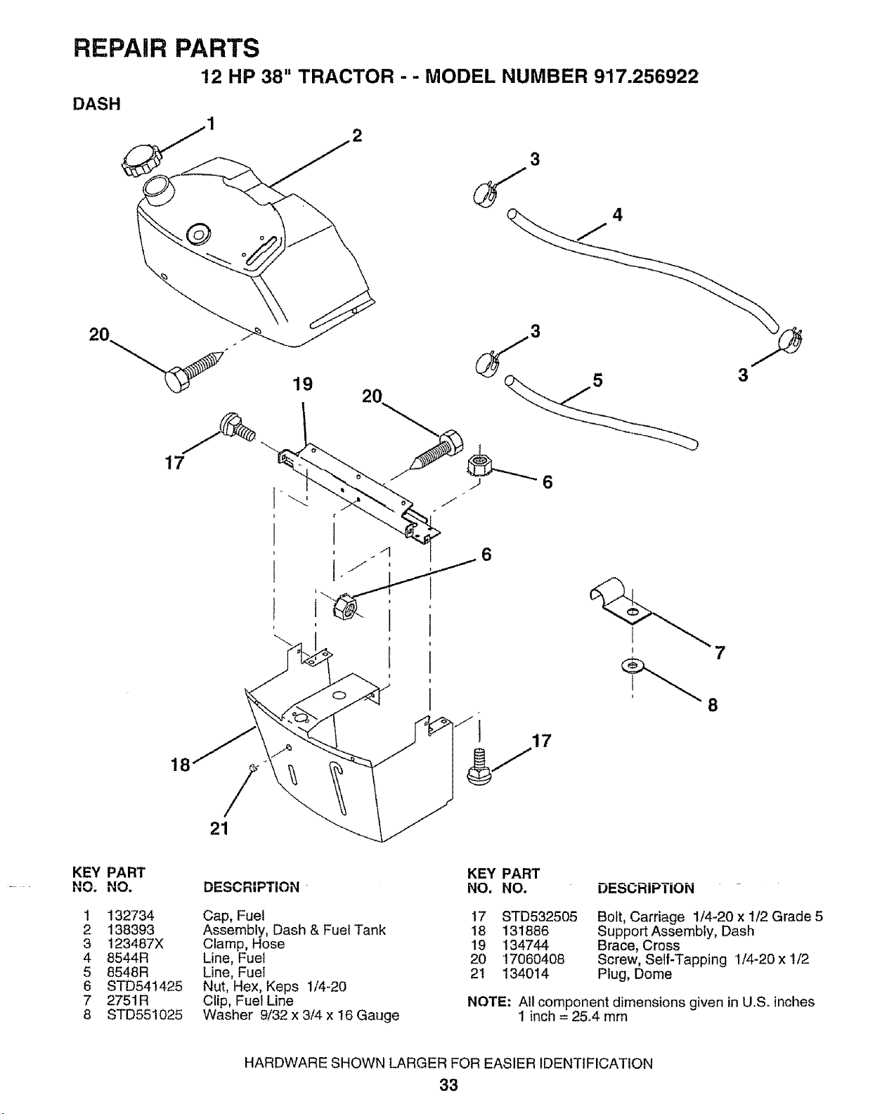
REPAIR PARTS
12 HP 38" TRACTOR - - MODEL NUMBER 917.256922
DASH
@
18
/
21
8
KEY PART
NO; NO.
1 132734
2 138393
3 123487X
4 8544R
5 8548R
6 STD541425
7 275tR
8 STD551025
DESCRIPTION
Cap, Fuel
Assembly, Dash & Fuel Tank
Clamp, Hose
Line, Fuel
Line, Fuel
Nut, Hex, Keps 1/4-20
Clip, Fuel Line
Washer 9/32 x 3/4 x !6 Gauge
KEY PART
NO. NO. DESCRIPTION
17 STD532505
18 131886
19 134744
20 17060408
2I 134O14
B01t, Carriage 1/4-20 x 1/2 Grade 5
Support Assembly, Dash
Brace, Cross
Screw, Self-Tapping 1/4-20 x 1/2
Plug, Dome
NOTE: All component dimensions given in U.S. inches
1 inch = 25.4 mm
HARDWARE SHOWN LARGER FOR EASIER IDENTIFICATION
33
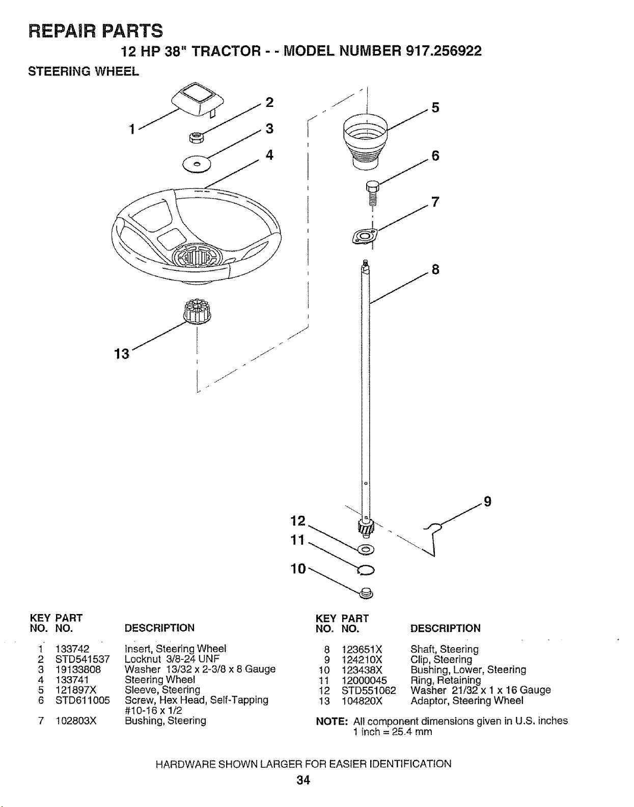
REPAIR PARTS
12 HP 38" TRACTOR - - MODEL NUMBER 917.256922
STEERING WHEEL
13
KEY PART
NO. NO.
1 133742
2 STD541537
3 19133808
4 133741
5 121897X
6 STD611005
7 102803X
DESCRIPTION
KEY PART
NO. NO. DESCRIPTION
insert, Steering Wheel 8
Locknut 3/8-24 UNF 9
Washer t3/32 x 2-3/8 x 8 Gauge 10
Steering Wheel 11
Sleeve, Steering 12
Screw, Hex Head, Self-Tapping 13
#10-16 x 1/2
Bushing, Steering
12365tX
124210X
t23438X
12000045
STD551062
104820X
Shaft, Steering
Clip, Steering
Bushing, Lower, Steering
Ring, Retaining
Washer 21/32 x I x 16 Gauge
Adaptor, Steering Wheel
NOTE: All component dimensions given in U.S. inches
1 inch = 2544 mm
HARDWARE SHOWN LARGER FOR EASIER IDENTIFICATION
34
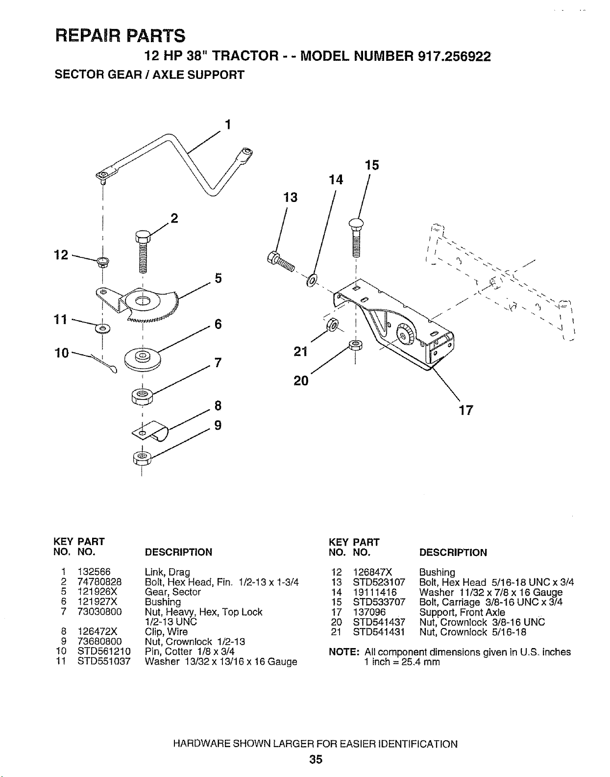
REPAIR PARTS
12 HP 38" TRACTOR - - MODEL NUMBER 917.256922
SECTOR GEAR / AXLE SUPPORT
2
10 7
8
13
21
20
17
KEY PART
NO, NO. DESCRIPTION
1 132566
2 74780828
5 121926X
6 121927X
7 73030800
8 t26472X
9 736808O0
10 STD561210
11 STD551037
KEY PART
NO. NO. DESCRIPTION
Link, Drag 12
Bolt, Hex Head, Fin. 1/2-13 x t-3/4 13
Gear, Sector 14
Bushing 15
Nut, Heavy, Hex, Top Lock 17
1/2-13 UNC 20
Clip, Wire 21
Nut, Crownlock 1/2-13
Pin, Cotter 1/8 x 3/4
Washer 13/32 x 13/16 x 16 Gauge
126847X
STD523107
19111416
STD533707
137096
STD541437
STD541431
Bushing
Bolt, Hex Head 5/16-18 UNC x 3/4
Washer 11/32 x 7/8 x 16 Gauge
Boit, Carriage 3/8-16 UNC x 3/4
Support, Front Axte
Nut, Crownlock 3/8:16 UNC
Nut, Crownlock 5/16-18
NOTE: All component dimensions given in U,S. inches
1 inch = 25.4 mm
HARDWARE SHOWN LARGER FOR EASIER IDENTIFICATION
35
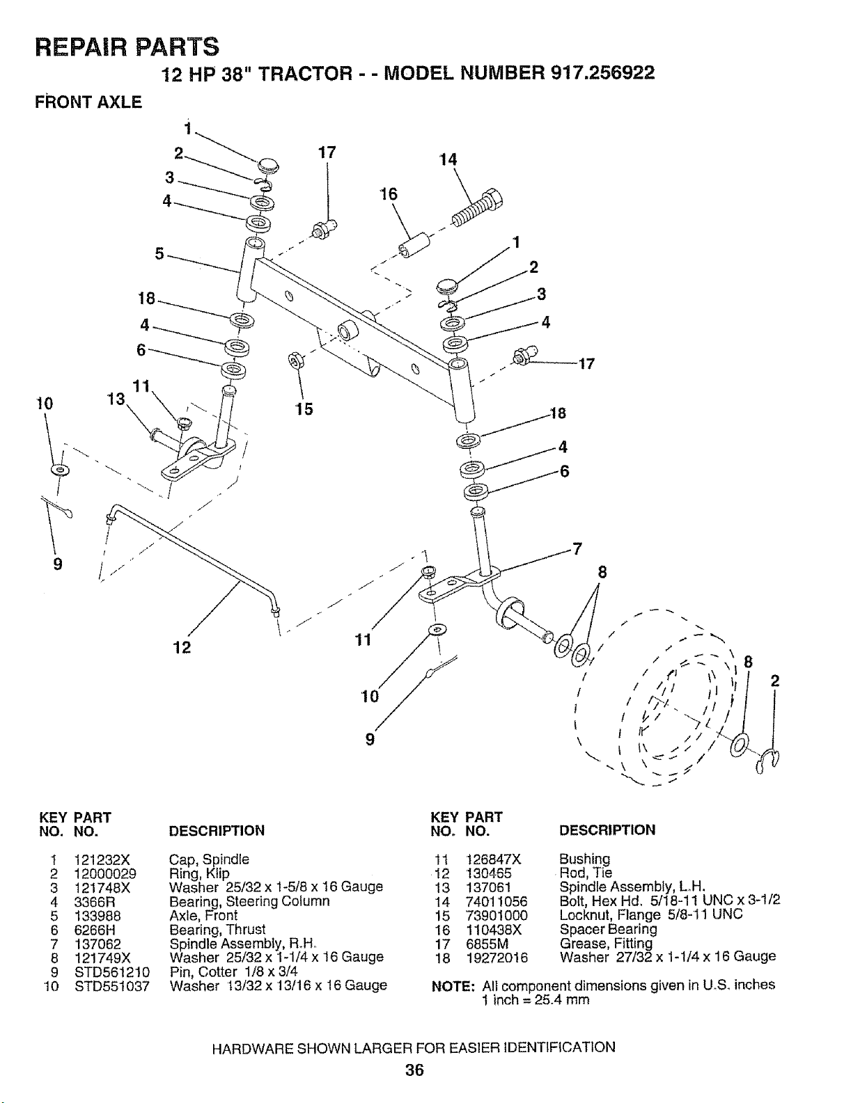
REPAIR PARTS
12 HP 38" TRACTOR - - MODEL NUMBER 917.256922
FRONT AXLE
10
/
KEY
NO.
I
2
3
4
5
6
7
8
9
10
12
15
11
10
9
PART
NO.
121232X
12000029
121748X
3366R
133988
6266H
'137062
121749X
STD561210
STD551037
DESCRIPTION
KEY PART
NO+ NO.
8
2
Cap, Spindle 11
Ring, Ktip 12
Washer 25132 x 1-5/8 x 16 Gauge 13
Bearing, Steering Column 14
Axle, Front 15
Bearing, Thrust !6
Spindle Assembly, RoHo 17
Washer 25/32 x 1-1/4 x 16 Gauge 18
Pin, Cotter 1/8 x 3/4
Washer 13/32 x 13/16 x 16 Gauge
DESCRIPTION
126847X
130465
137061
74011056
73901000
110438X
6855M
19272016
Bushing
Rod, Tie
Spindle Assembly, LH.
Bolt, Hex Hd. 5/t8-11 UNC x 3-1/2
Locknut, Flange 5/8-I 1 UNC
Spacer Bearing
Grease, Fitting
Washer 27/32 x 1-1/4 x 16 Gauge
NOTE: All component dimensions given in U_S. inches
I inch = 25.4 mm
HARDWARE SHOWN LARGER FOR EASIER IDENTIFICATION
36
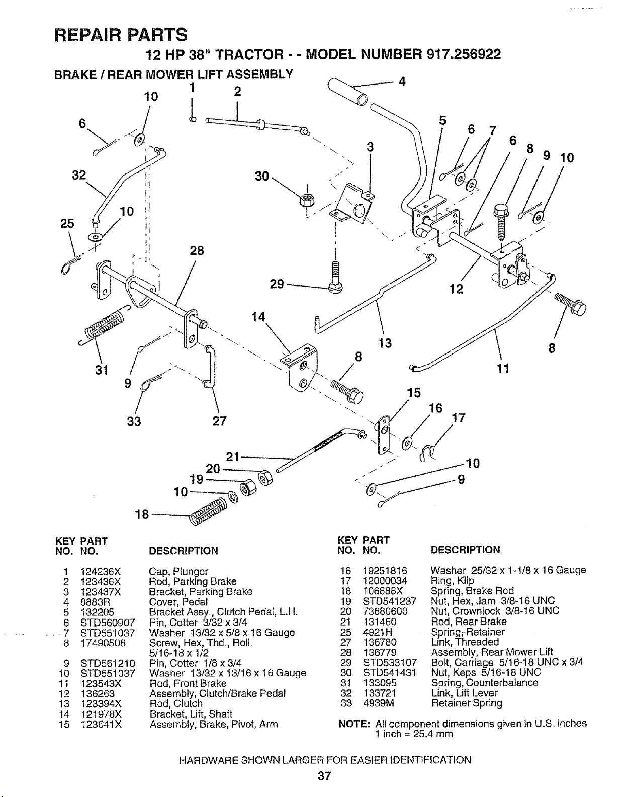
REPAIR PARTS
12 HP 38" TRACTOR - - MODEL NUMBER 917.256922
BRAKE / REAR MOWER LIFT ASSEMBLY
10 1 2
32
28
3
6
14
_. 15
11
6
8
9 10
8
KEY PART
NO. NO.
KEY PART
DESCRIPTION NO. NO. DESCRIPTION
1 124236X
2 123436X
3 123437X
4 8883R
5 1322O5
6 STD560907
7 STD551037
8 17490508
9 STD561210
10 STD551037
11 123543X
12 136263
13 123394X
14 121978X
15 123641X
Cap, Plunger 16
Rod, Parking Brake t7
Bracket, Parking Brake 18
Cover, Pedal 19
Bracket Assy., Clutch Pedal, LH. 20
Pin, Cotter 3/32 x 3/4 21
Washer t3/32 x 5/8 x 16 Gauge 25
Screw, Hex, Thd., Roll. 27
5/16-18 x 1/2 28
Pin, Cotter 1/8 x 3/4 29
Washer 13/32 x 13/16 x 16 Gauge 30
Rod, Front Brake 31
Assembly, Clutch/Brake Pedal 32
Rod, Clutch 33
Bracket, Lift, Shaft
Assembly, Brake, Pivot, Arm
19251816
12000034
106888X
STD541237
73680600
131460
4921H
136780
136779
STD533107
STD541431
133095
133721
4939M
Washer 25/32 x 1-1/8 x 16 Gauge
Ring, Klip
Spring, Brake Rod
Nut, Hex, Jam 3/8-16 UNC
Nut, Crownlock 3/8-16 UNC
Rod, Rear Brake
Spring,Retainer
Link, Threaded
Assembly, Rear Mower Lift
Bolt, Carriage 5/16-18 UNC x 3/4
Nut, Keps 5/16-18 UNC
Spring, Counterbalance
Link, Lift Lever
Retainer Spring
NOTE: All component dimensions given in U°S inches
1 inch = 25.,4 mm
HARDWARE SHOWN LARGER FOR EASIER IDENTIFICATION
37
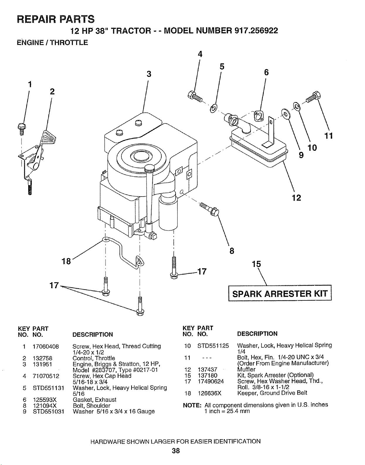
REPAIR PARTS
12 HP 38" TRACTOR - - MODEL NUMBER 917.256922
ENGINE / THROTTLE
4
3 6
2
9
11
10
KEY PART
NO. NO.
1 17060408
2 132758
3 131951
4 71070512
5 STD551131
6 125593X
8 121094X
9 STD551031
DESCRIPTION
KEY PART
NO. NO.
\
12
8
15
\
Screw, Hex Head, Thread Cutting 10
t/4-20 x 1/2
Control, Throttle 11
Engine, Briggs & Stratton, 12 HP,
Model #283707, Type #0217-01 12
Screw, Hex Cap Head 15
5/t6-t8 x 3/4 17
Washer, Lock, Heavy Helical Spring
5/t 6 18
Gasket, Exhaust
Bolt, Shoulder
Washer 5/16 x 3/4 x 16 Gauge
DESCRIPTION
STD55 ! 125
137437
137180
17490624
t26636X
Washer, Lock, Heavy Helical Spring
1/4
Bolt, Hex, Fin, 1/4-20 UNC x 3/4
(Order From Engine Manufacturer)
Muffler
Kit, Spark Arrester (Optional)
Screw, Hex Washer Head, Thd_,
Roll 3/8-16 x t-1/2
Keeper, Ground Drive Belt
NOTE: All component dimensions given in U.S, inches
1 inch = 25.4 mm
HARDWARE SHOWN LARGER FOR EASIER IDENTIFICATION
38
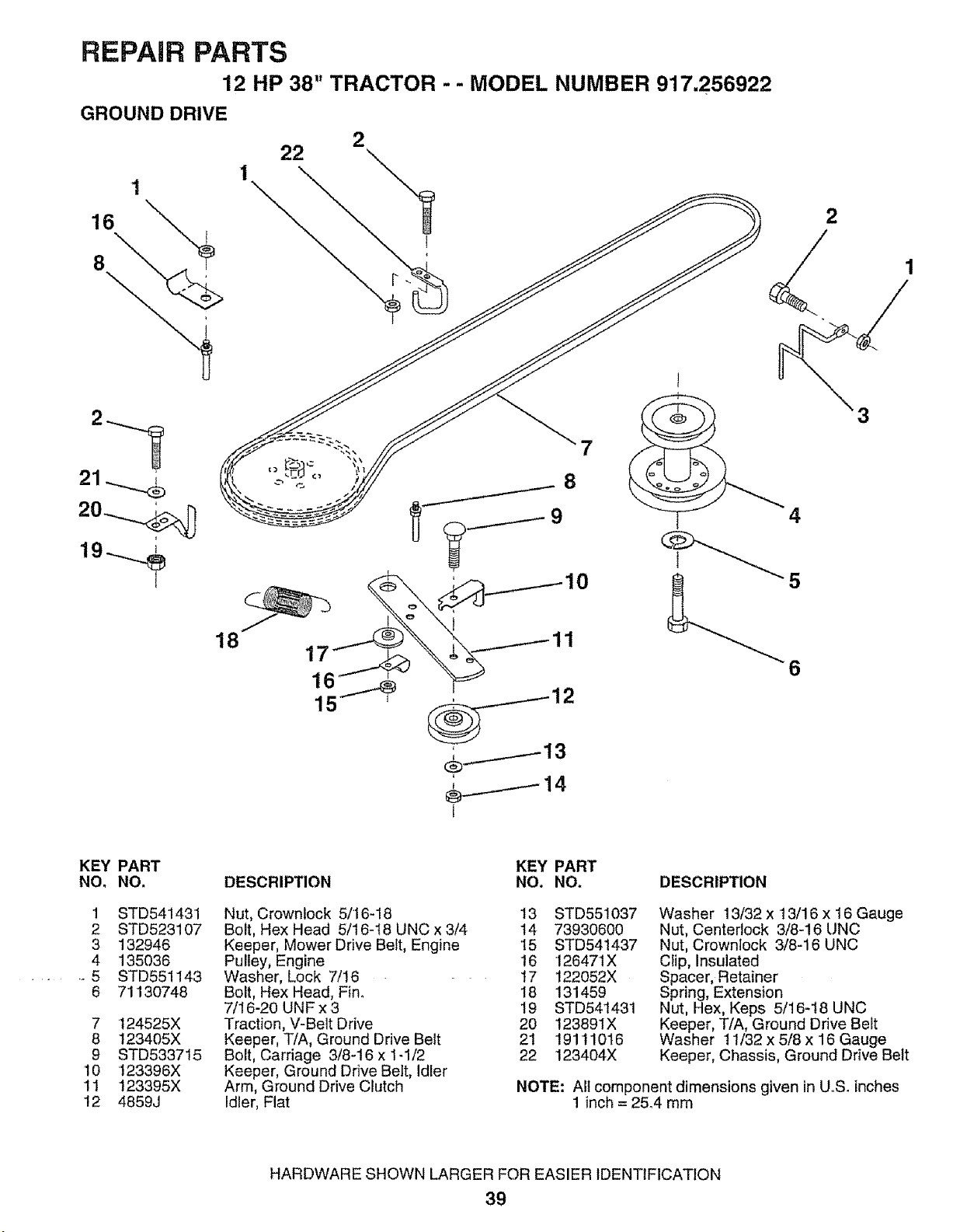
REPAIR PARTS
12 HP 38" TRACTOR - - MODEL NUMBER 917.256922
GROUND DRIVE
2-"1
21.....%
20...__
18
7
2
4
6
KEY PART
NO, NO,
1
2
3
4
• ,_ 5
6
7
8
9
10
11
12
STD541431
STD523107
132946
135036
STD551143
71130748
t24525X
t23405X
STD533715
123396X
123395X
4859J
DESCRIPTION
Nut, Crownlock 5/'16-18
Bolt, Hex Head 5/16-18 UNC x 3/4
Keeper, Mower Drive Belt, Engine
Pulley, Engine
Washer, Lock 7/16
Bolt, Hex Head, Fin_
7/16-20 UNF x 3
Traction, V-Belt Drive
Keeper, T/A, Ground Drive Belt
Bolt, Carriage 3/8-16 x t-1/2
Keeper, Ground Drive Belt, Idler
Arm, Ground Drive Clutch
Idler, Flat
KEY PART
NO. NO, DESCRIPTION
13 STD551037
14 73930600
't5 STD541437
16 126471X
t7 122052X
18 131459
t9 STD541431
20 123891X
21 19111016
22 123404X
Washer 13/32 x t3/16 x 16 Gauge
Nut, Centerlock 3/8-16 UNC
Nut, Crownlock 3/8-16 UNC
Clip, Insulated
Spacer, Retainer
Spring, Extension
Nut, Hex, Keps 5/16-18 UNC
Keeper, T/A, Ground Drive Belt
Washer 11/32 x 5/8 x 16 Gauge
Keeper, Chassis, Ground Drive Belt
NOTE: All component dimensions given in U.S. inches
1 inch = 25.4 mm
HARDWARE SHOWN LARGER FOR EASIER IDENTIFICATION
39
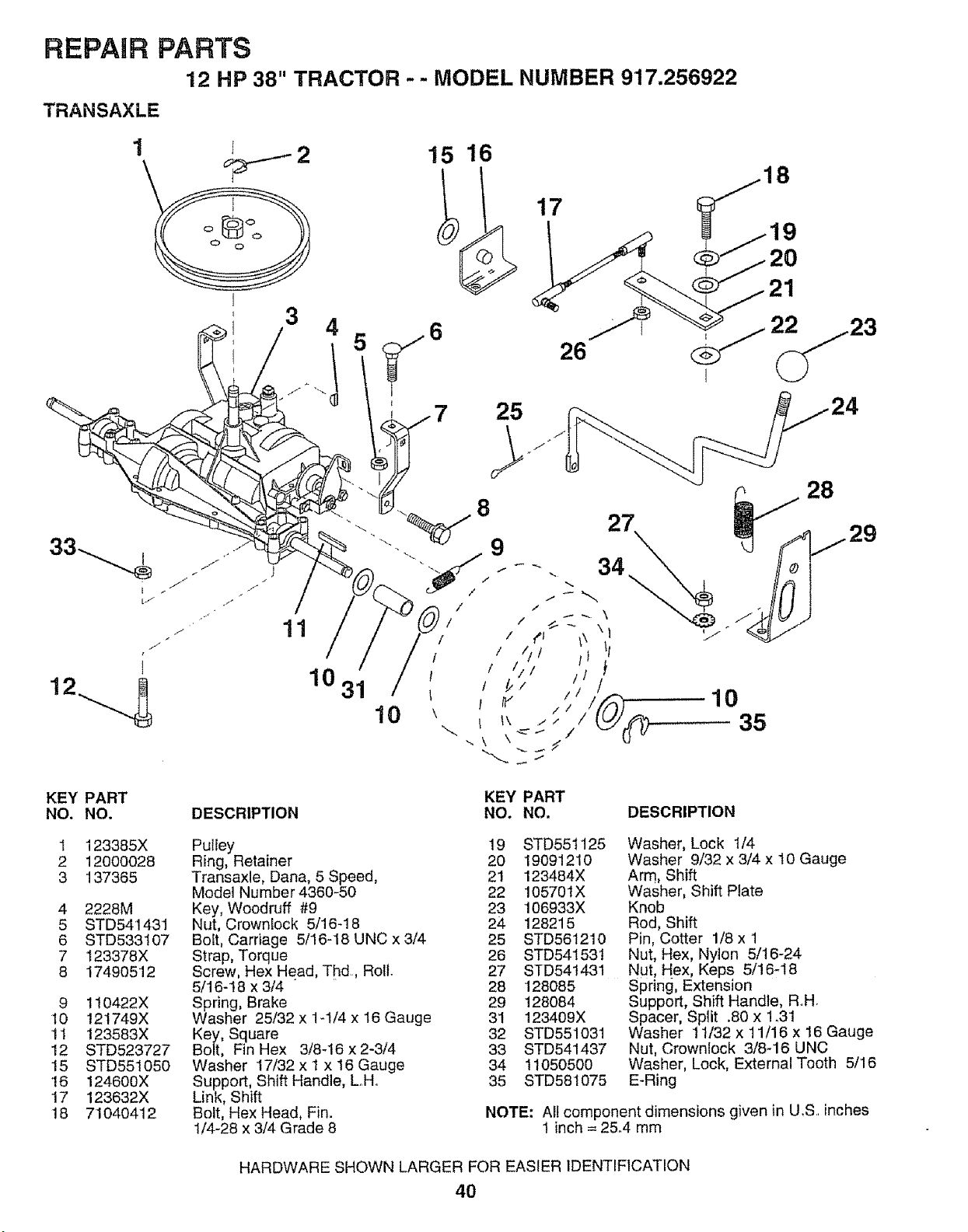
REPAIR PARTS
12 HP 38" TRACTOR - - MODEL NUMBER 917.256922
TRANSAXLE
3 4
15 16
I
7 25
17
26
KEY PART
NO. NO.
1 123385X
2 12000028
3 137365
4 2228M
5 STD541431
6 STD533107
7 123378X
8 17490512
9 110422X
10 121749X
11 123583X
12 STD523727
15 STD551050
16 124600X
17 123632X
18 71040412
11
1031
10
10
35
DESCRIPTION
KEY PART
NO. NO. DESCRIPTION
Pulley 19
Ring, Retainer 20
Transaxle, Dana, 5 Speed, 2!
Model Number 4360-50 22
Key, Woodruff #9 23
Nut, Crownlock 5/16_18 24
Bolt, Carriage 5/16-18 UNC x 3/4 25
Strap, Torque 26
Screw, Hex Head, Thd., Roll. 27
5/16-18 x 3/4 " 28
Spring, Brake 29
Washer 25/32 x 1-t/4 x 16 Gauge 31
Key, Square 32
Bolt, Fin Hex 3/8-16 x 2-3/4 33
Washer 17/32 x I x 16 Gauge 34
Support, Shift Handle, L.H. 35
Link, Shift
Bolt, Hex Head, Fin.
1/4-28 x 3/4 Grade 8
STD551125
19091210
123484X
105701X
106933X
128215
STD561210
Washer, Lock 1/4
Washer 9/32 x 3/4 x 10 Gauge
Arm, Shift
Washer, Shift Plate
Knob
Rod, Shift
Pin, Cotter 1/8 x '1
STD541531 Nut, Hex, Nylon 5/16-24
STD541431 NUt Hex, Keps 5/16-18
128085
128084
123409X
STD551031
STD541437
11050500
STD581075
Spring, Extension
Support, Shift Handle, R°H°
Spacer, Split .80 x 1.31
Washer 11/32 x 11/16 x 16 Gauge
Nut, Crownlock 3/8-16 UNC
Washer, Lock, External Tooth 5/16
E-Ring
NOTE: All component dimensions given in U.S. inches
1 inch = 25.4 mm
HARDWARE SHOWN LARGER FOR EASIER IDENTIFICATION
40
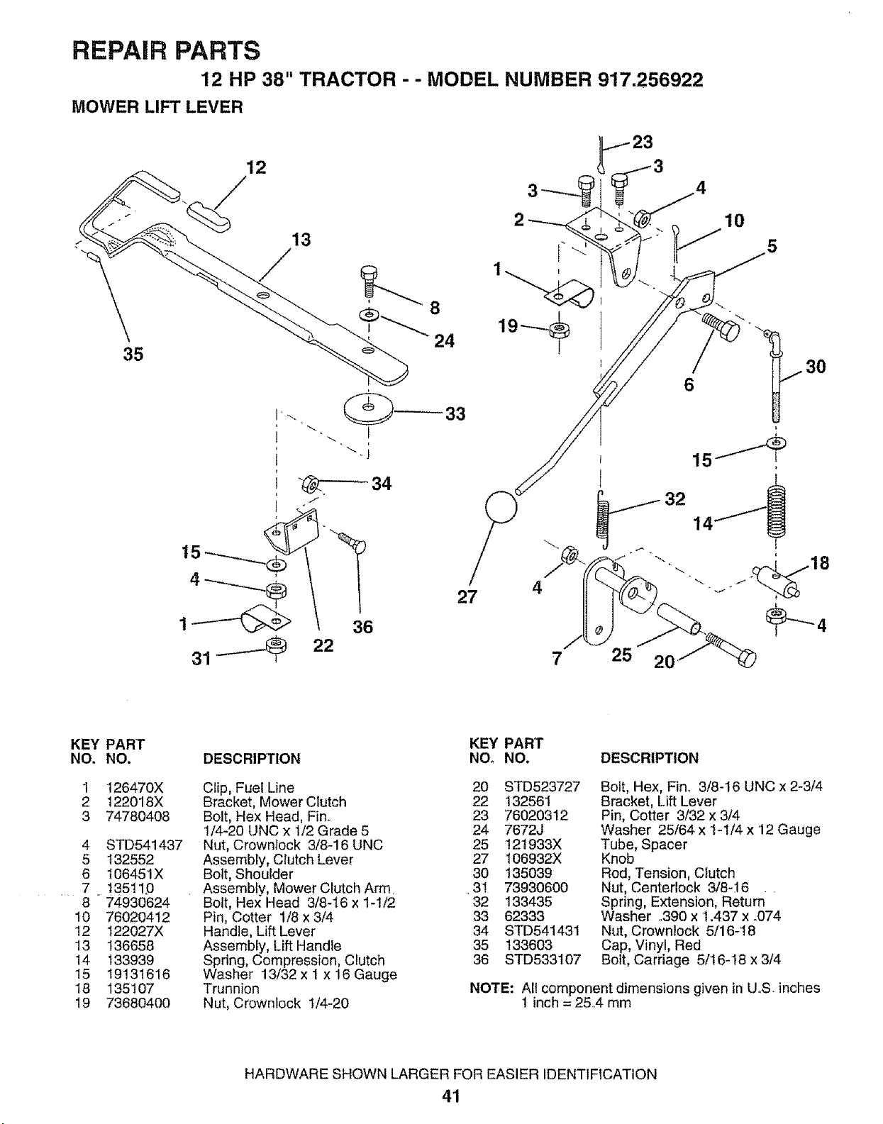
REPAIR PARTS
12 HP 38" TRACTOR - - MODEL NUMBER 917.256922
MOWER LIFT LEVER
12
13
35
J
36
22
27
4
7
25 2(
KEY
NO.
1
2
3
4
5
6
., 7.
8
!0
12
13
14
15
18
19
PART
NO.
126470X
122018X
74780408
STD541437
132552
t06451X
!3511D
74930624
76020412
122027X
136658
133939
19131616
135107
73680400
KEY PART
DESCRIPTION NOo NO,
Clip, Fuel Line 20 STD523727
Bracket, Mower Clutch 22 132561
Bolt, Hex Head, Fin° 23 76020312
1/4-20 UNC x 1/2 Grade 5 24 7672J
Nut, Crownrock 3/8-16 UNC 25 121933X
Assembly, Clutch Lever 27 106932X
Bolt, Shoulder 30 135039
Assembly, Mower Clutch Arm ,31 73930600
Bolt, Hex Head 3/8-I6 x 1-!/2 32 133435
Pin, Cotter 1/8 x 3/4 33 62333
Handle, Lift Lever 34 STD541431
Assembly, Lift Handle 35 133603
Spring, Compression, Clutch 36 STD533107
Washer 13/32 x 1 x 16 Gauge
Trunnion
Nut, Crownlock 1/4-20
DESCRIPTION
Bolt, Hex, Finn 3/8-16 UNC x 2-3/4
Bracket, Lift Lever
Pin, Cotter 3/32 x 3/4
Washer 25/64 x 1=1/4 x 12 Gauge
Tube, Spacer
Knob
Rod, Tension, Clutch
Nut, Centerlock 3/8-16
Spring, Extension, Return "
Washer ,,390 x 1.437 x °074
Nut, Crownlock 5/16-18
Cap, Vinyl, Red
Bolt, Carriage 5/16-18 x 3/4
NOTE: All component dimensions given in UoS, inches
1 inch = 25,4 mm
HARDWARE SHOWN LARGER FOR EASIER IDENTIFICATION
41
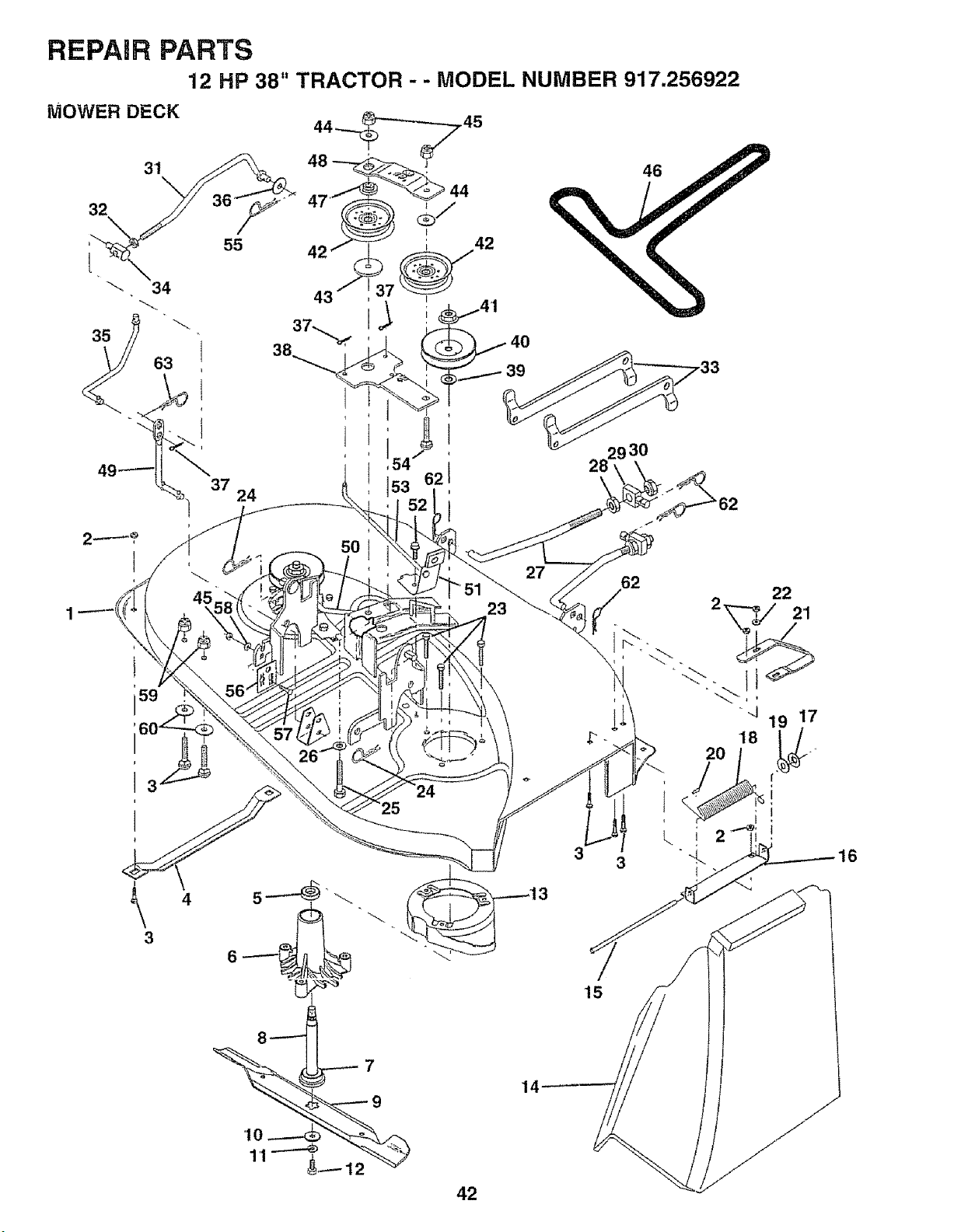
REPAIR PARTS
12 HP 38" TRACTOR - - MODEL NUMBER 917.256922
MOWER DECK
31
32
55
37
24
4
3
42
14
3
15
22
2'1
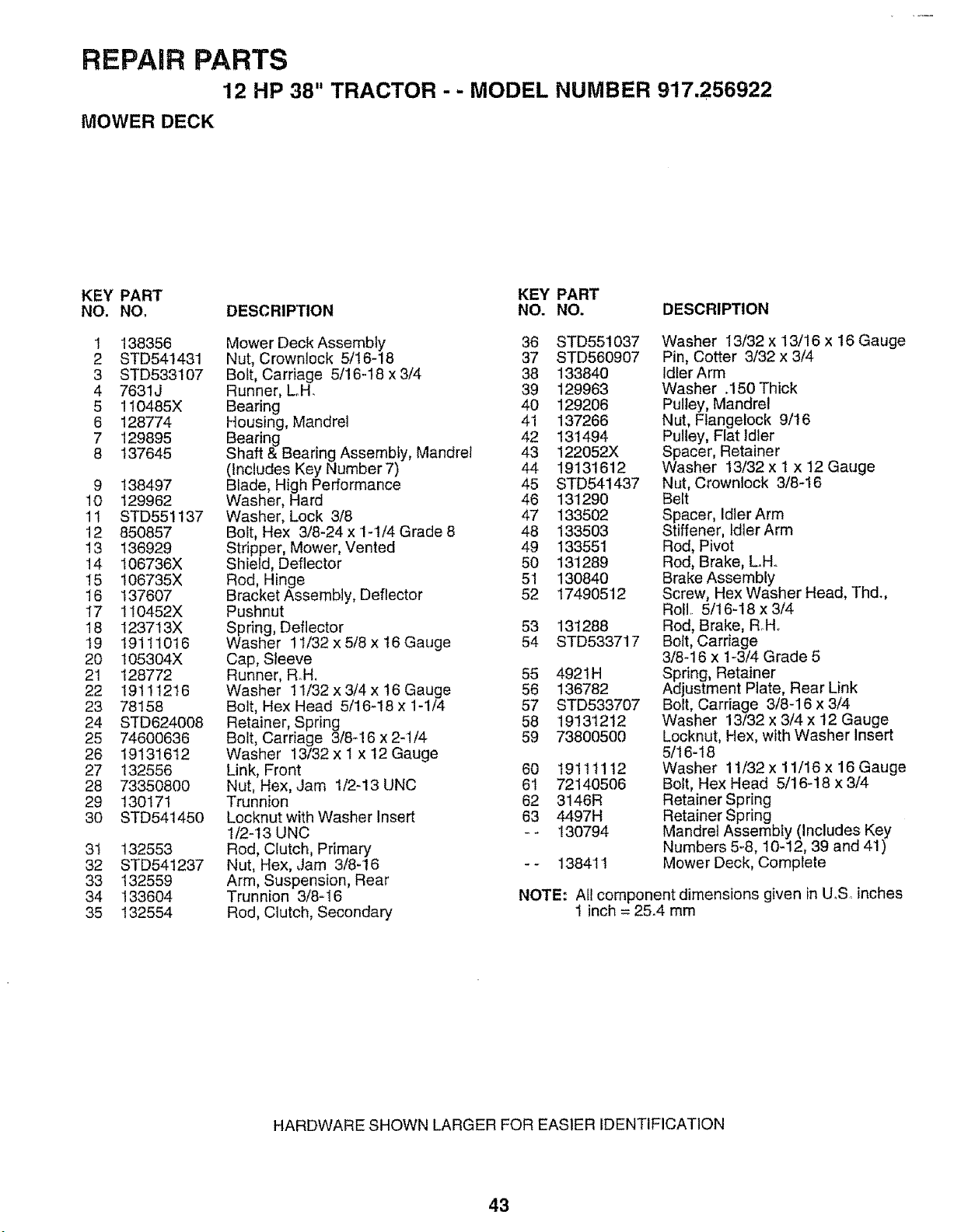
REPAIR PARTS
12 HP 38" TRACTOR - - MODEL NUMBER 917.256922
MOWER DECK
KEY PART KEY PART
NO. NO, DESCRIPTION NO. NO. DESCRIPTION
1 138356
2 STD541431
3 STD533107
4 7631J
5 110485X
6 128774
7 129895
8 137645
9 138497
10 129962
11 STD551137
12 850857
13 136929
14 106736X
15 106735X
16 137607
17 110452X
18 123713X
19 19111016
20 105304X
21 128772
22 19111216
23 78158
24 STD624008
25 74600636
26 19131612
27 132556
28 73350800
29 130171
30 STD541450
31 132553
32 STD541237
33 132559
34 133604
35 132554
Mower Deck Assembly 36
Nut, Crownlock 5/I6-18 37
Bolt, Carriage 5/16-18 x 3/4 38
Runner, Loll. 39
Bearing 40
Housing, Mandrel 41
Bearing 42
Shaft & Bearing Assembly, Mandrel 43
(Includes Key Number 7) 44
Blade, High Performance 45
Washer, Hard 46
Washer, Lock 3/8 47
Bolt, Hex 3/8-24 x 1-1/4 Grade 8 48
Stripper, Mower, Vented 49
Shield, Deflector 50
Rod, Hinge 51
Bracket Assembly, Deflector 52
Pushnut
Spring, Deflector 53
Washer 11/32 x 5/8 x I6 Gauge 54
Cap, Sleeve
Runner, Roll. 55
Washer 11/32 x 3/4 x 16 Gauge 56
Bolt, Hex Head 5/16q8 x 1-1/4 57
Retainer, Spring 58
Bolt, Carriage 3/8-16 x 2-1/4 59
Washer 13/32 x t x 12 Gauge
Link, Front 60
Nut, Hex, Jam 1/2-13 UNC 61
Trunnion 62
Locknut with Washer Insert 63
1/2-13 UNC - -
Rod, Clutch, Primary
Nut, Hex, Jam 3/8-16 - -
Arm, Suspension, Rear
Trunnion 3/8-I6
Rod, Clutch, Secondary
STD551037
STD560907
133840
129963
129206
137266
131494
122052X
19131612
STD541437
131290
133502
133503
133551
131289
130840
17490512
131288
STD533717
4921H
136782
STD533707
19131212
73800500
19111112
72140506
3146R
4497H
130794
138411
Washer 13/32 x '13/16 x 16 Gauge
Pin, Cotter 3/32 x 3/4
Idler Arm
Washer .150 Thick
Pulley, Mandrel
Nut, Flangelock 9/16
Pulley, Fiat Idler
Spacer, Retainer
Washer !3/32 x t x 12 Gauge
Nut, Crowntock 3/8-16
Belt
Spacer, Idler Arm
Stiffener, Idler Arm
Rod, Pivot
Red, Brake, L.H.
Brake Assembly
Screw, Hex Washer Head, Thd.,
Roll. 5/16-18 x 3/4
Rod, Brake, RoHo
Bolt, Carriage
3/8q 6 x 1-3/4 Grade 5
Spring, Retainer
Adjustment Plate, Rear Link
Bolt, Carriage 3/8-16 x 3/4
Washer 13/32 x 3/4 x 12 Gauge
Locknut, Hex, with Washer Insert
5/16-t8
Washer 11/32 x 11/16 x 16 Gauge
Bolt, Hex Head 5/16-!8 x 3/4
Retainer Spring
Retainer Spring
Mandrel Assembty (Includes Key
Numbers 5-8, 10-12, 39 and 41)
Mower Deck, Complete
NOTE: All component dimensions given in U_S inches
1 inch = 25.4 mm
HARDWARE SHOWN LARGER FOR EASIER IDENTIFICATION
43
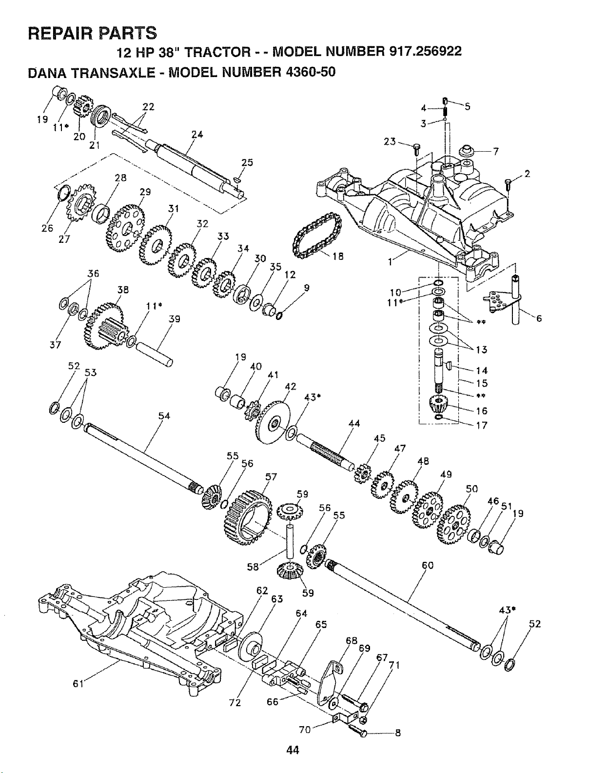
REPAIR PARTS
12 HP 38" TRACTOR - - MODEL NUMBER 917.256922
DANA TRANSAXLE - MODEL NUMBER 4360-50
36
37
52
53
19
40
54
55
56
57
!5 12
42
43 b
44
59
56
55
4-5
l
14
15
16
L__ 17
47
48
49
50
62
63
59
64
65
68
69
6O
43*
52
72 66
7O
44
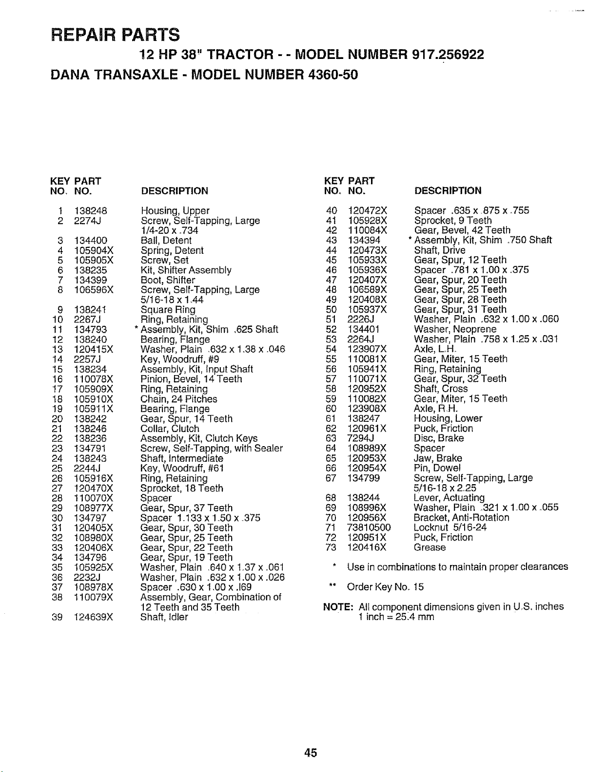
REPAIR PARTS
!2 HP 38" TRACTOR -- MODEL NUMBER 917.256922
DANA TRANSAXLE - MODEL NUMBER 4360-50
KEY PART KEY PART
NO. NO. DESCRIPTION NOo NO_ DESCRIPTION
1 138248
2 2274J
3 134400
4 105904X
5 105905X
6 138235
7 134399
8 106596X
9 138241
10 2267J
11 134793
12 138240
13 120415X
14 2257J
15 138234
16 110078X
17 105909X
18 105910X
19 105911X
20 138242
21 138246
22 138236
23 134791
24 138243
25 2244J
26 105916X
27 !20470X
28 110070X
29 108977X
30 134797
31 120405X
32 108980X
33 120406X
34 134796
35 105925X
36 2232J
37 108978X
38 I!0079X
39 124639X
Housing, Upper 40
Screw, Self-Tapping, Large 41
1/4-20 x °734 42
Ball, Detent 43
Spring, Detent 44
Screw, Set 45
Kit, Shifter Assembly 46
Boot, Shifter 47
Screw, Self-Tapping, Large 48
5/t6-18 x 1.44 49
Square Ring 50
Ring, Retaining 51
* Assembly, Kit, Shim .625 Shaft 52
Bearing, Flange 53
Washer, Plain .632 x 1.38 x .046 54
Key, Woodruff, #9 55
Assembly, Kit, Input Shaft 56
Pinion, Bevel, 14 Teeth 57
Ring, Retaining 58
Chain, 24 Pitches 59
Bearing, Flange 60
Gear, Spur, t4 Teeth 61
Collar, Clutch 62
Assembly, Kit, Clutch Keys 63
Screw, Self-Tapping, with Sealer 64
Shaft, Intermediate 65
Key, Woodruff, #61 66
Ring, Retaining 67
Sprocket, 18 Teeth
Spacer 68
Gear, Spur, 37 Teeth 69
Spacer 1.133 x 1.50 x .375 70
Gear, Spur, 30 Teeth 71
Gear, Spur, 25 Teeth 72
Gear, Spur, 22 Teeth 73
Gear, Spur, 19 Teeth
Washer, Plain .640 x 1_37x .061
Washer, Plain .632 x 1.00 x .026
Spacer .630 x 1,00 x .169
Assembly, Gear, Combination of
12 Teeth and 35 Teeth
Shaft, Idler
120472X
t05928X
110084X
134394
120473X
105933X
105936X
120407X
106589X
120408X
105937X
2226J
134401
2264J
123907X
1t0081X
105941X
110071X
120952X
110082X
123908X
138247
120961X
7294J
108989X
120953X
120954X
134799
138244
108996X
t20956X
73810500
120951X
120416X
Spacer _635 x.875 x ..755
Sprocket, 9 Teeth
Gear, Bevel, 42 Teeth
* Assembly, Kit, Shim ..750 Shaft
Shaft, Drive
Gear, Spur, 12 Teeth
Spacer .781 x 1.00 x °375
Gear, Spur, 20 Teeth
Gear, Spur, 25 Teeth
Gear, Spur, 28 Teeth
Gear, Spur, 31 Teeth
Washer, PIain .632 x !.00 x _060
Washer, Neoprene
Washer, Ptain .758 x 1_25 x .03I
Axle, L_H.
Gear, Miter, 15 Teeth
Ring, Retaining
Gear, Spur, 32 Teeth
Shaft, Cross
Gear, Miter, 15 Teeth
Axle, R.H.
Housing, Lower
Puck, Friction
Disc, Brake
Spacer
Jaw, Brake
Pin, Dowel
Screw, Self-Tapping, Large
5/16-18 x 225
Lever, Actuating
Washer, Plain o321 x 1.00 x °055
Bracket, AntFRotation
Locknut 5/16-24
Puck, Friction
Grease
* Use in combinations to maintain proper clearances
** Order Key No. 15
NOTE: All component dimensions given in U..S_inches
1 inch = 25_4 mm
45
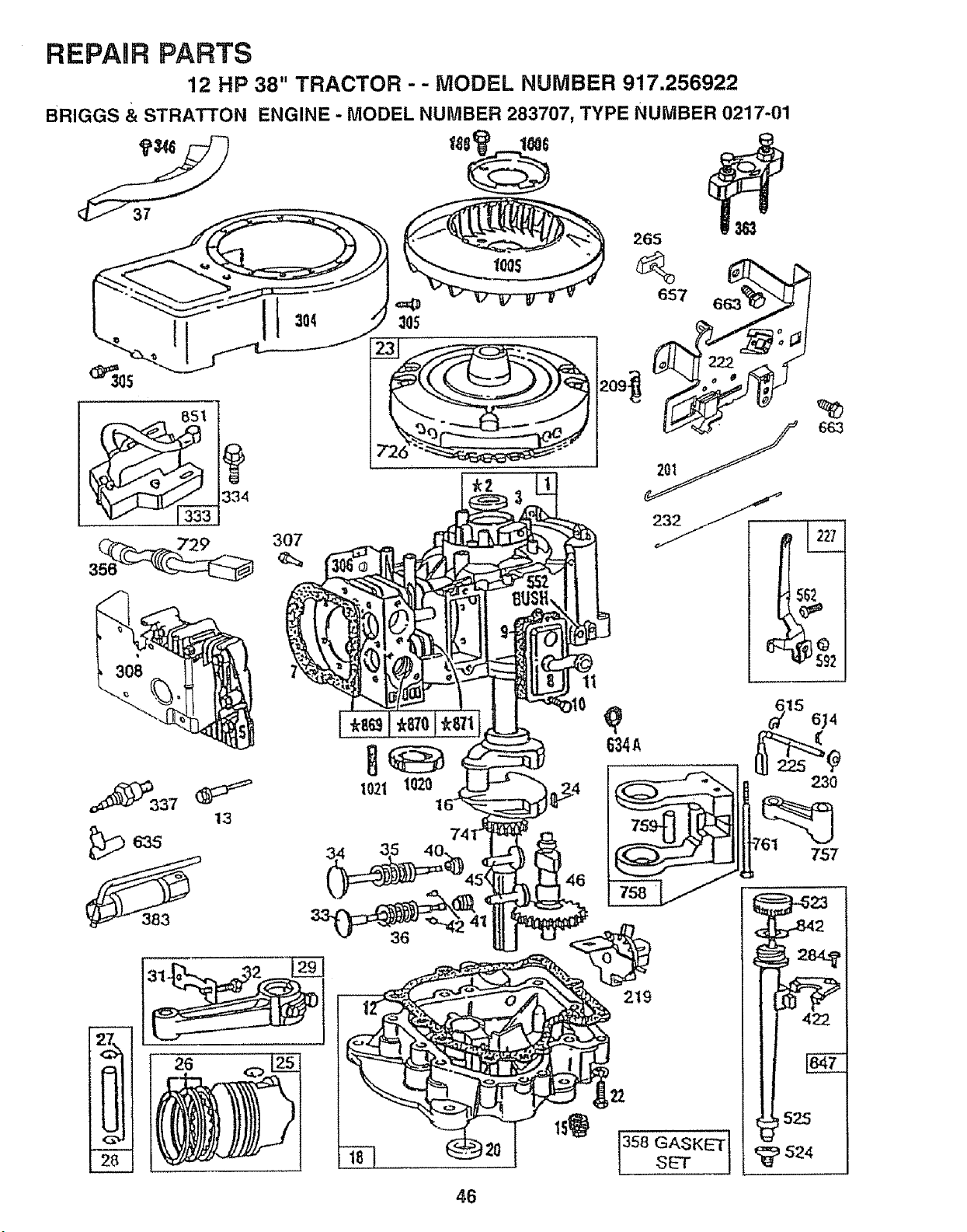
REPAIR PARTS
12 HP 38" TRACTOR - - MODEL NUMBER 917.256922
BRIGGS & STRATTON ENGINE - MODEL NUMBER 283707, TYPE NUMBER 0217-01
_729 307
P::337
13
265
11
23O
757
219
GASKET I
SET j
46
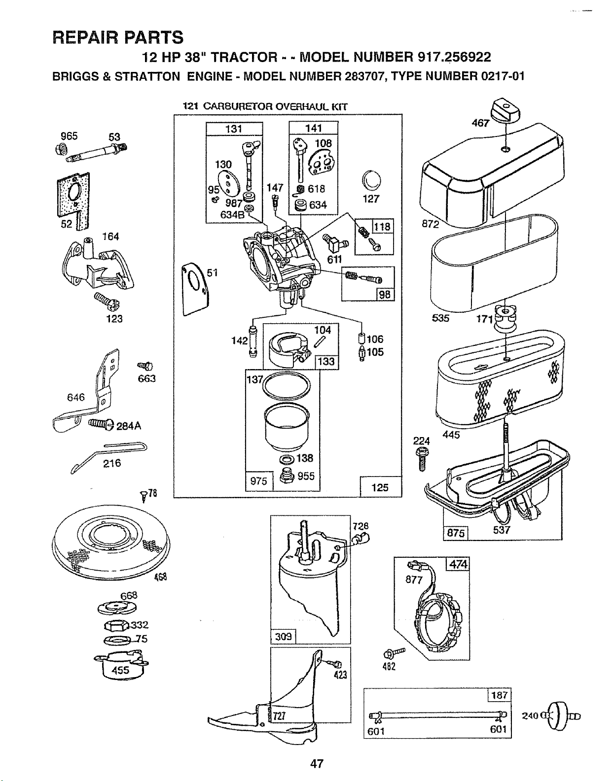
REPAIR PARTS
12 HP 38" TRACTOR - - MODEL NUMBER 917.256922
BRIGGS & STRATTON ENGINE - MODEL NUMBER 283707, TYPE NUMBER 0217-01
965 53
%
123
84A
1_'78
121 CARSUFIETOR OVERHAUL KIT
131
130
141
_Q 618
_634
©
127
_138
_105
125
•" 423
535 1711
445
482
601
240 (_
47
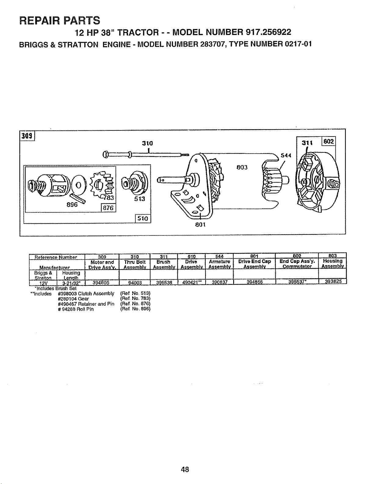
REPAIR PARTS
12 HP 38" TRACTOR - - MODEL NUMBER 917.256922
BRIGGS & STRATTON ENGINE - MODEL NUMBER 283707, TYPE NUMBER 02'17-01
896
310
801
Reference Number I ............309 _-" 3ti I SIQ
Motor end I ThruB°!t Brush I Drive
Manufacturer Dr ve Ass'v. I Assembly Assembly L Assemb|v
Briggs& i Housing I I
!
__ t 04oo_ _ 39ss38!4oo4z!"_
L 12V i 3-21/32" ! 394805
"lncfL_eSBrush Set
•'Includes #398003 Clutch Assembly (Ref No1513)
#26D104 Gear (Ref No. 783)
#490467 Retainer and Pln (Ref. No., 878)
# 94288 Roll Pin (Ref No, 896)
Armature j Drive End Cap End Cap Ass'y.
Assembly | Assembly Commutator
390837 t 394856 ._._j ........ '_"7"
48
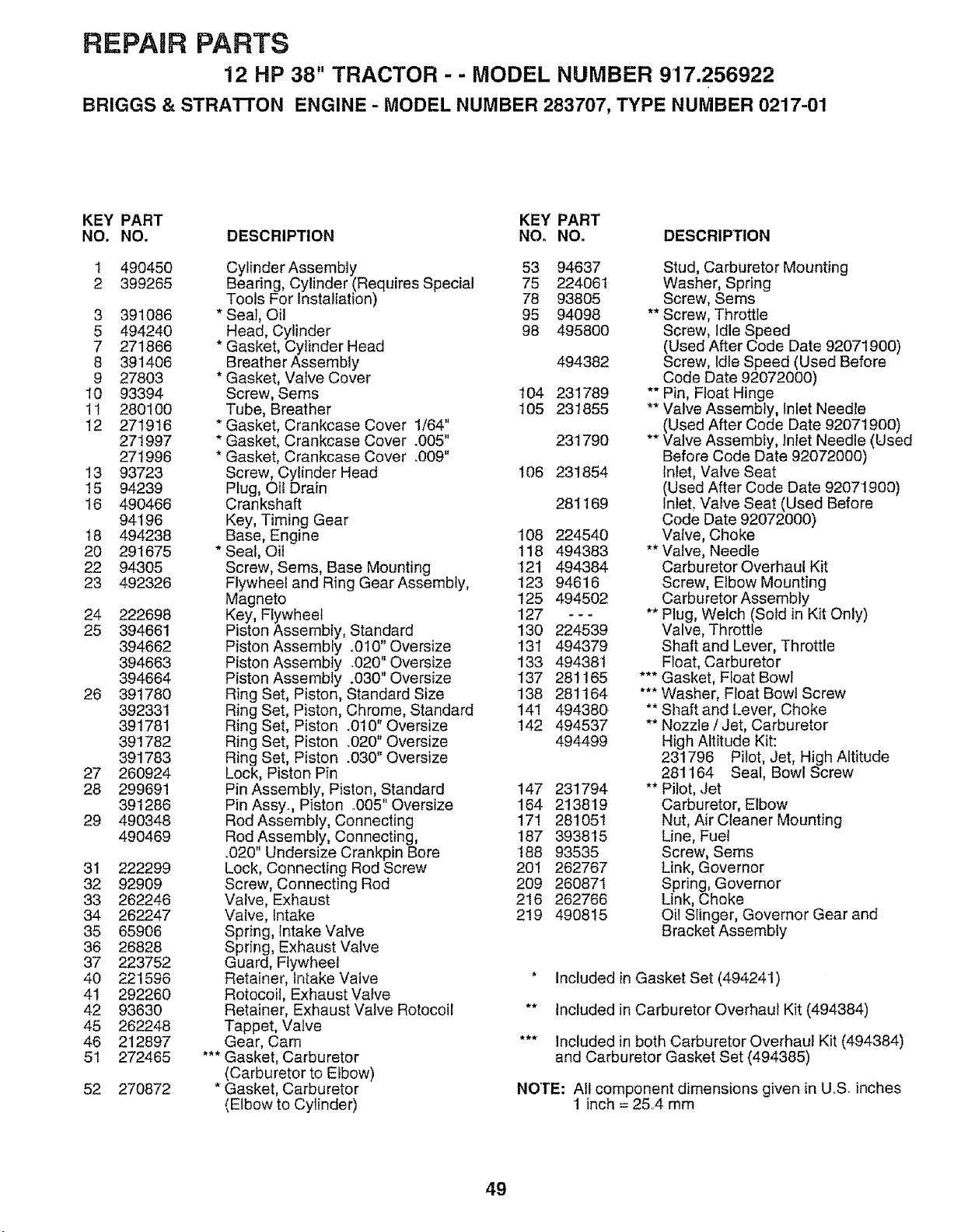
REPAIR PARTS
12 HP 38" TRACTOR - - MODEL NUMBER 917.256922
BRIGGS & STRATTON ENGINE - MODEL NUMBER 283707, TYPE NUMBER 0217-01
KEY PART KEY PART
NO. NO. DESCRIPTION NO° NO_ DESCRIPTION
1 490450
2 399265
3 391086
5 494240
7 271866
8 391406
9 27803
10 93394
11 280100
12 27'1916
271997
271996
13 93723
15 94239
16 490466
94196
18 494238
20 291675
22 94305
23 492326
24 222698
25 394661
394662
394663
394664
26 391780
392331
391781
39'1782
391783
27 260924
28 299691
391286
29 490348
490469
31 222299
32 92909
33 262246
34 262247
35 65906
36 26828
37 223752
40 221596
41 292260
42 93630
45 262248
46 212897
51 272465
52 270872
Cylinder Assembly 53 94637
Bearing, Cylinder (Requires Special 75 224061
Tools For Installation) 78 93805
* Seat, Oil 95 94098
Head, Cylinder 98 495800
* Gasket, Cylinder Head
Breather Assembly 494382
* Gasket, Vafve Cover
Screw, Seres 104 231789
Tube, Breather 105 231855
* Gasket, Crankcase Cover 1/64"
* Gasket, Crankcase Cover .005" 231790
* Gasket, Crankcase Cover .009"
Screw, Cylinder Head 106 231854
Plug, Oii Drain
Crankshaft 281169
Key, Timing Gear
Base, Engine 108 224540
* Seal, Oil 118 494383
Screw, Sems, Base Mounting '121 494384
Flywheel and Ring Gear Assembly, 123 94616
Magneto 125 494502
Key, Flywheel 127 - - -
Piston Assembly, Standard !30 224539
Piston Assembfy .010"Oversize 131 494379
Piston Assembly .020" Oversize 133 494381
Piston Assembly .030" Oversize 137 28!165
Ring Set, Piston, Standard Size 138 281164
Ring Set, Piston, Chrome, Standard 141 494380
Ring Set, Piston .010" Oversize 142 494537
Ring Set, Piston °020" Oversize 494499
Ring Set, Piston .030" Oversize
Lock, Piston Pin
Pin Assembly, Piston, Standard 147 231794
Pin Assy.., Piston _005" Oversize 164 213819
Rod Assembly, Connecting 171 281051
Rod Assembly, Connecting, 187 393815
.020" Undersize Crankpin Bore 188 93535
Lock, Connecting Rod Screw 20! 262767
Screw, Connecting Rod 209 260871
Valve, Exhaust 216 262766
Valve, Intake 219 490815
Spring, Intake Valve
Spring, Exhaust Valve
Guard, Flywheel
Retainer, Intake Valve
Rotocoi!, Exhaust Valve
Retainer, Exhaust Valve Rotocoil
Tappet, Valve
Gear, Cam
*** Gasket, Carburetor
(Carburetor to Elbow)
* Gasket, Carburetor
(Elbow to Cylinder)
Stud, Carburetor Mounting
Washer, Spring
Screw, Seres
** Screw, Throttle
Screw, Idle Speed
(Used After Code Date 92071900)
Screw, Idle Speed (Used Before
Code Date 92072000)
** Pin, Float Hinge
** Valve Assembly, Inlet Needle
(Used After Code Date 92071900)
** Valve Assembly, Inlet Needle (Used
Before Code Date 92072000)
Inlet, Valve Seat
(Used After Code Date 92071900)
InfeL Valve Seat (Used Before
Code Date 92072000)
Valve, Choke
** Valve, Needle
Carburetor Overhaul Kit
Screw, Elbow Mounting
Carburetor Assembly
** Plug, Welch (Sold in Kit Only)
Valve, Throttle
Shaft and Lever, Throttle
Float, Carburetor
*** Gasket, Float Bowl
*** Washer, Float Bowl Screw
** Shaft and Lever, Choke
** Nozzle / Jet, Carburetor
High Altitude Kit:
231796 Pilot, Jet, High Altitude
281164 Seal, Bowl Screw
** Pilot, Jet
Carburetor, Elbow
Nut, Air Cleaner Mounting
Line, Fuel
Screw, Sems
Link, Governor
Spring, Governor
Link, Choke
Oil Slinger, Governor Gear and
Bracket Assembly
* Included in Gasket Set (494241)
** Included in Carburetor Overhaul Kit (494384)
*** Included in both Carburetor Overhaul Kit (494384)
and Carburetor Gasket Set (494385)
NOTE: All component dimensions given in U.S. inches
1 inch = 25.4 mm
49
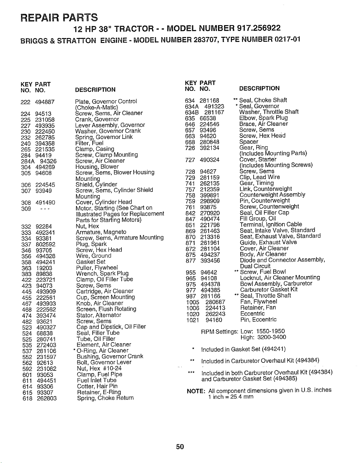
REPARRPARTS
12 HP 38" TRACTOR - - MODEL NUMBER 917.256922
BRIGGS & STRATTON ENGINE - MODEL NUMBER 283707, TYPE NUMBER 0217-01
KEY PART KEY PART
NO. NO. DESCRIPTION NO. NO. DESCRIPTION
222 494887
224 94513
225 231058
227 493935
230 222450
232 262785
240 394358
265 221535
284 94419
284A 94326
304 494269
305 94608
306 224545
307 93949
308 491490
309 ---
332 92284
333 492341
334 93381
337 802592
346 93705
356 494328
358 494241
363 19203
383 89838
422 22372't
423 94073
445 493909
455 222561
467 493903
468 222562
474 393474
482 93621
523 490327
524 68838
525 280741
535 272403
537 281106
552 231597
562 92613
592 231082
601 93053
611 494451
614 93306
615 93307
618 262803
Plate, Governor Control 634 281168
(Choke-A-Matic) 634A 491323
Screw, Seres, Air Cleaner 634B 281167
Crank, Governor 635 66538
Lever Assembly, Governor 646 224546
Washer, Governor Crank 657 93496
Spring, Governor Link 663 94620
Filter, Fuel 668 280848
Clamp, Casing 726 392134
Screw, Clamp Mounting
Screw, Air Cleaner 727 490324
Housing, Blower
Screw, Sems, Blower Housing 728 94627
Mounting 729 281159
Shield, Cylinder 741 262135
Screw, Sems, Cylinder Shield 757 212359
Mounting 758 399891
Cover, Cylinder Head 759 298909
Motor, Starting (See Chart on 761 93875
Illustrated Pages for Replacement 842 270920
Parts for Starting Motors) 847 490474
Nut, Hex 851 221798
Armature, Magneto 869 261463
Screw, Sems, Armature Mounting 870 213316
Plug, Spark 871 261961
Screw, Hex Head 872 28'1104
Wire, Ground 875 494237
Gasket Set 877 393456
Puller, Flywheel
Wrench, Spark Plug 955 94642
Clamp, Oil Filler Tube 965 94108
Screw, Sems 975 494378
Cartridge, Air Cleaner 977 494385
Cup, Screen Mounting 987 281166
Knob, AirCleaner 1005 280687
Screen, Elush Rotating 1006 2244!3
Stator, Alternator 1020 262243
Screw, Seres 1021 94160
Cap and Dipstick, Oil Filler
Seal, Filler Tube
Tube, Oil Filler
Element, Air Cleaner
* O-Ring, Air Cleaner
Bushing, Governor Crank
Bolt, Governor Lever
Nut, Hex #10_24 "
Clamp, Fuel Pipe
Fuel Inlet Tube
Cotter, Hair Pin
Retainer, E-Ring
Spring, Choke Return
** Seal, Choke Shaft
* Seat, Governor
Washer, Throttle Shaft
Elbow, Spark Plug
Brace, Air Cleaner
Screw, Sems
Screw, Hex Head
Spacer
Gear, Ring
(Includes Mounting Parts)
Cover, Starter
(Includes Mounting Screws)
Screw, Sems
Clip, Lead Wire
Gear, Timing
Link, Counterweight
Counterweight Assembly
Pin, Counterweight
Screw, Countenweight
Seal, Oil Filler Cap
Fill Group, Oil
Terminal, Ignition Cable
Seat, Intake Valve, Standard
Seat, Exhaust Valve, Standard
Guide, Exhaust Valve
Cover, Air Cleaner
Body, Air Cleaner
Diode and Connector Assembly,
Dual Circuit
** Screw, Fuel Bowl
Locknut, Air Cleaner Mounting
Bowl Assembly, Carburetor
Carburetor Gasket Kit
** Seal, Throttle Shaft
Fan, Flywheel
Retainer, Fan
Eccentric
Pin, Eccentric
RPM Settings: Low: 1550-1950
High: 3200-3400
* Included in Gasket Set (494241)
** Included in Carburetor Overhaul Kit (494384)
*** Included in both Carburetor Overhaul Kit (494384)
and Carburetor Gasket Set (494385)
NOTE: All component dimensions given in UoS, inches
1 inch = 25,4 mm
5O

SUGGESTED GUIDE FOR SIGHTING SLOPES FOR SAFE OPERATION
O1
SIGHTING
GUIDE
ONLY RIDE UP AND DOWN HILL,
NOT ACROSS HILL
SIGHT AND HOLD THIS LEVEL WITH
SKY LINE OR TREE.
!
15 ° MAX.
1 _ Operate your Tractor up and down the face of slopes (not i
AJk greater than 15°), never across the face. Make turns gradu-
ally to prevent tipping or loss of control. Exercise extreme
caution when changing direction on slopes. ....
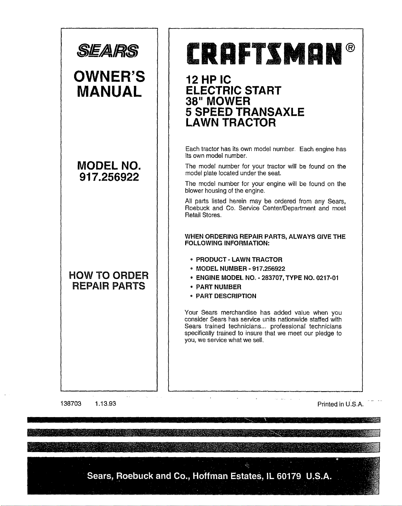
S_ A/RS
OWNER'S
MANUAL
MODEL NO.
917.256922
HOW 3"0 ORDER
REPAIR PARTS
I:RRFISMRII ®
12 HP IC
ELECTRIC START
38" MOWER
5 SPEED TRANSAXLE
LAWN TRACTOR
Each tractor has its own model number. Each engine has
its own model number°
The model number for your tractor will be found on the
model plate located under the seat.
The model number for your engine will be found on the
blower housing of the engine°
All parts listed herein may be ordered from any Sears,
Roebuck and Co. Service Center/Department and most
Retail Stores,,
WHEN ORDERING REPAIR PARTS, ALWAYS GIVE THE
FOLLOWING INFORMATION:
o PRODUCT - LAWN TRACTOR
o MODEL NUMBER - 917.256922
= ENGINE MODEL NO. - 283707, TYPE NO. 0217-01
• PART NUMBER
• PART DESCRIPTION
Your Sears merchandise has added value when you
consider Sears has service units nationwide staffed with
Sears trained technicians.., professional technicians
specifically trained to insure that we meet our pledge to
you, we service what we sell
138703 1.13.93
I I II'IIIHIIIII
Printed in U_S,,A. ......
IIII I ,! 'ZI
_,1III IIIIl"lI_111IIH Illll'lIlll'l '


