Loading ...
Loading ...
Loading ...
muffler and spark arresting screen
which meets the requirements of Cali-
fornia Codes 4442 and 4443. All U.S.
forest land and the states of California,
Idaho, Maine, Minnesota, New JerSey,
Oregon, and WashingtOn require by
law that many internal combustion en-
gines be equipped with a spark arres-
tor screen. If you operate in a locale
where such regulations exist, you are
legally responsible for installing and
maintaining the operating condition of:.
these parts. Failure to do so is a viola_
tion of the law: Refer tothe MAINTE-
NANCE section in this manual. :
CARTON CONTENTS
Check carton contents against the fol-
lowing list.
Model 358,798540
° Trimmer
° Shield
• Assist Handle
• Wing Nut (attached to shield)
, Container of Oil
Model 358.798570
• Trimmer
- Shield
- Assist Handle
° Wing Nut (attached to shield)
. Container of Oil
• Spool with 20 ft. of line
. One gallon gasoline container
° Pair of gloves
° Bulk line - 200 feet
Examine parts for damage. Do not use
damaged parts.
NOTE: If you need assistance or find
parts missing or damaged, call the
1-800 number listed on the front of this
manual.
It is normal for the fuel filter to rattle in
the empty fuel tank.
Finding fuel or oil residue on muffler is
normal due to carburetor adjustments
and testing done by the manufacturer.
ASSEMBLY
:WARNING: If received assembled,
repeat all steps to ensure your unit is
properly assembled and all fasteners
are secure.
Ber sure to assemble the handle to the
unit before you assemble the shield.
ATTACHING THE HANDLE
(some units are already assembled)
WARNING: Make sure unit is properly
assembled and all fasteners are secure.
j.7-6
Make sure knob isassembled on this side.
• Assemble handle to the unit asshown;
make sure bottom of handle is seated
in the groove inthe trigger housing.
NOTE,: Adjustment knob must be as-
sembled on the side of the unit oppo-
site the operator's position.
• Pivot handle to acomfortable position.
Tighten handle securely.
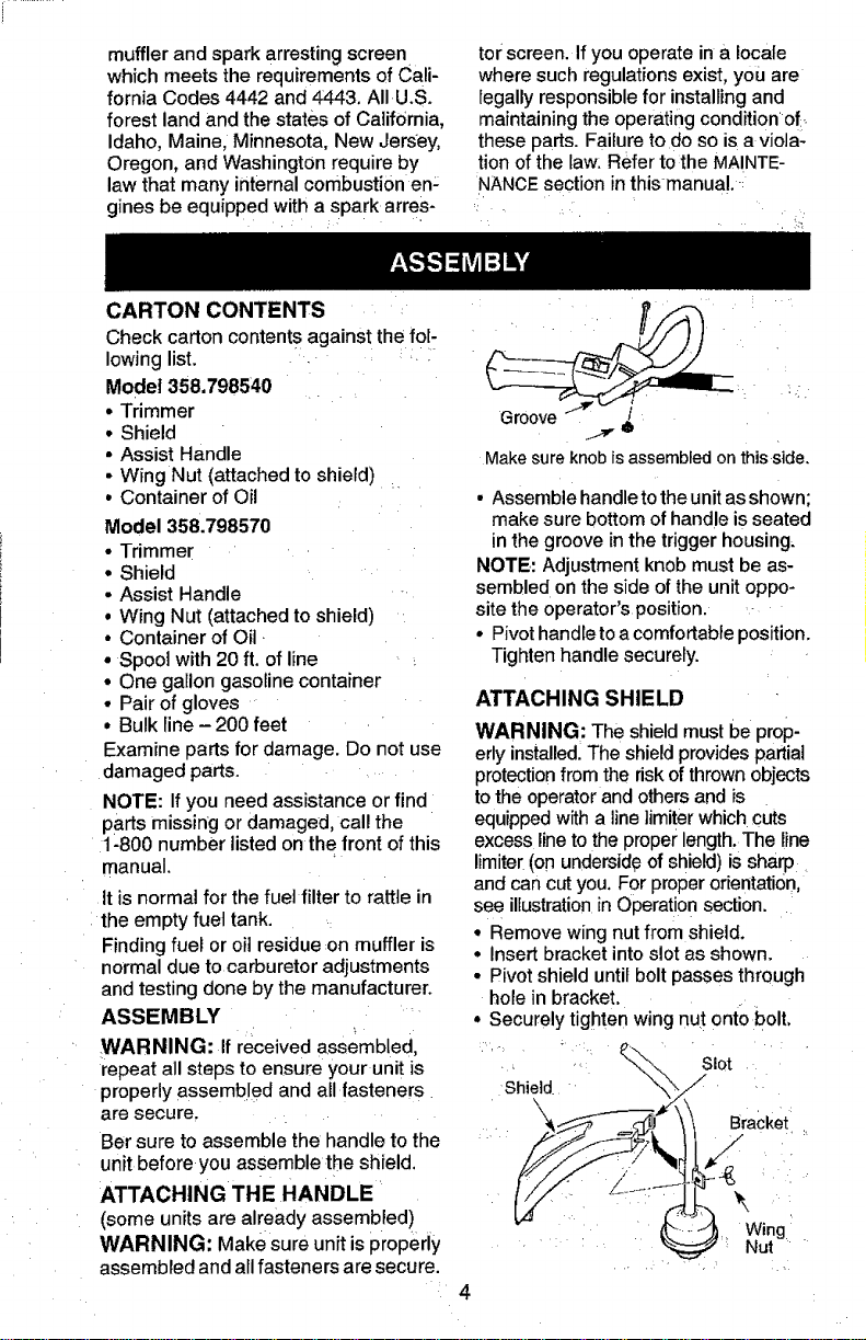
ATTACHING SHIELD
WARNING: The shield must be prop-
erly installed. The shield provides partial
protection from the riskofthrownobjects
to the operatorand others and is
equippedwith a line ]imiter which cuts
excess line to the properlength.The line
limiter(on undersideof shield) is sharp
and can cut you. For proper orientation,
see illustratio_in Operation section.
° Remove wing nut from shield.
• Insert bracket into s!ot as shown.
• Pivot shield until bolt passes through
hole in bracket.
° Securely tighten wing nut onto bolt,
_'_ Slot
Shield J
_ __"_ Bracket
Loading ...
Loading ...
Loading ...