OWNER'S MANUAL
CAUTION
RISKOFELECTRICSHOCK
\ DONOTOPEN
CAUTION: TO REDUCE THE RISK OF
ELECTRIC SHOCK, DO NOT REMOVE
COVER (OR BACK). NO USER-SERVICEABLE
PARTS INSIDE. REFER SERVICING TO
QUALIFIED SERVICE PERSONNEL.
1
2
3
4
5
6
7
8
• Explanation of Graphical Symbols
The lightning flash with arrowhead symbol,within an
equilateral triangle, is intended to alert you to the
presence o1uninsulaled "dangerous voltage" within
the product's enclosure thai l]lay be of sufficient
magnitude to constitute a risk o1electric shock to
10
persolls,
The exclanlation point within an equilateral triangle
is intended to alert you to the presence of important 11
ol?eratingand maintenance (_lvicing) instructions in
, the literature accompanying the appliance. 12
Note to CATV system installer:
This reminder is provided to call the CATV system
installer's attention to Article 820-40 of the NEC that
provides guidelines for proper grounding and, in
particuhtr, specifies that the cable ground shall be
connected to the grounding system of the building, as
close to the point of cable entry as practical.
IMPORTANT
Please record the serial nnmber of tiffs unit in the space
below.
MODEL:
Serial No.:
The serial number is located on the rear of the unit.
Retain this Owner's Manual in a sale place for future
reference.
13
14
Read these instructions.
Keep these iustructiuus.
Heed all warnings.
Follow all instnlctions.
Do not use this apparatus near water.
Clean only with dry cloth.
Do not block any ventilation openings. Install in accordance
with the manulhcturer's instructions.
Do not install near any heat sources such as radiators, heat
registers, stoves, or uther apparatus (including amplifiers)
that produce heat.
Do not delcat the safety purpose of the polarized ur
grounding-type plug. A polarized plug has two blades with
one wider than the other. A gruunding type plug has two
blades and a third grounding prong. The wide blade or the
third pruug are provided for your safety. If the provided plug
does not fit intu your outlet, consult an electrician for
replacement uf the obsolete outlet.
Protect the power culal from being walked un or pinched
particularly at plugs, convenience receptacles, and the point
where they exit Ii'om the apparatus.
Only use attachments/accessuries specified by the
manufacturer.
Use only with the cart. stand, tripod,
bracket, or table specified by the
manu!hcturer, or sold with the apparatus.
When a cart is used. use caution when
moving the cart/apparatus cumbiuation to
avoid ii]jury frum tip-over.
Unplug this apparatus during lightning storms or when
unused for lung periuds of time.
Relk:r all servicing to qualified service persunneh Servicing
is required when the apparatus has been damaged in any
way, such as power-supply cord or plug is damaged, liquid
has been spilled or o[_iects have fallen into the apparatus, the
apparatus has been exposed to rain or moisture, does nut
operate normally, ur has been dropped.
We Want You Listening For A Lifetime
YAMAHA mad the Electronic Industries Association's (-'onsumer Electronics Group want >ou to get the most out of your
equipment by playing it at a safe level. One that lets the suund cume through h)ud and clear without annoying blaring ur
distortiun and. most importantly, without alfecting your sensitive hearing. Since hearing damage from loud sounds is
often undetectable until it is tou late, YAMAHA and the Electronic Industries Association's Consumer Electronics Group
reconlnleud you to avuid prulonged expusure fron] excessive v(i]tlti]e levels.
LTSTE_I_G
FCC INFORMATION (for US customers)
1 IMPORTANT NOTI(E: DO NOT MODIFY THIS Complimu:e with FCC regulatkms dues not guarantee that
INIT! interference will not occur in all installations. If this
This product, when installed as indicated in the product is found to he the source of interlerence, which
instructions contained in this m:mual, meets FCC c:m be determined by turning the unit "OFF" and "ON".
requirmuents. Modifications not expressly approved by please try to eliminate the problem by using one of the
Yamaha may w_id your authority, granted by the FCC. to following measures:
use the product. Relocate either this product or the device that is being
IMPORTANT: When comlecting this product to afli:cted by the interference.
accessories and/or another product use only high quality Utilize power outlets that are on different branch (circuit
shielded cables. Cable/s supplied with this product MUST breaker or fllse) circuits or install AC line filter/s.
be used. Follow all installation instructions. Failure to
In the case of radio or TV interference, relocate/reorient
li_llow instructions could void your FCC authorization to the antenna. If the antmma lead-in is 300 ohm ribbon lead.
use this product in the USA. change the lead-in to coaxial type cable.
NOTE: This product has been tested and found to comply
If these corrective measures do not produce satisfactory
with the requirements listed in FCC Regulations. Part 15
for Class "B" digital devices. Compliance with these results, please contact the local retailer authorized to
requirements provides a reasonable level of assurance that distribute this type of product. If you can not locate the
your use uf this product in a residential environment will appropriate retailer, please contact Yamaha Electronics
not result in harmful interference with other electronic Corp.. U.S.A. 6660 Orangethorpe Ave. Buena Park. CA
devices. 9(1620.
This equipment generatesklses radio frequencies and. if The above statements apply ONLY to those products
not installed and used according to the instructions found distributed by Yamaha (orporation of America or its
in the users manual, may cause interl'erence harmful to the subsidiaries.
operation of other electronic devices.
1 Toassurethefinestperformance,pleasereadthismanual
carefully.Keepitinasafeplaceforfuturereference.
2 Installthissoundsysteminawellventilated,cool.dry,clean
placeawayt'rom direct sunlight, heat sources, vibration.
dust. moisture, and/or cold. Allow ventilation space of at least
30 cm on the top, 20 cm on the lell and right, and 20 cm on
the back of this unit.
3 Locate this unit away from other electrical appliances, motors.
or transformers to avoid humming sounds.
4 Do not expose this unit to sudden temperature changes from
cold to hot. attd do not locate this unit in art mwironment with
high humidity (i.e. a room with a humidifier) to prevent
condensation inside this unit. which may cause an electrical
shock, fire. damage to this unit. and/or personal injury.
5 Avoid installing this unit where loreigu ohjects may fall onto
this unit and/or this unit may be exposed to liquid dripping or
splashing. On the top of this unit. do not place:
Other components, as they may cause damage and/or
discoloration on the surface of this unit.
Burning ot_jects (i.e. candles), as they may cause fre.
damage to this trait, attd/or personal injury.
Containers with liquid in them. as they may fall and liquid
may cause electrical shock to the user and/or damage to
this unit.
6 Do not cover this unit with a newspaper, tablecloth, curtain.
etc. in order not to obstruct heat radiation. If the temperature
inside this unit rises, it may cause fire. damage to this unit.
and/or personal il_jnry.
7 Do not plug in this unit to a wall outlet tmtil all connections
are complete.
8 Do not operate this unit upside-down. It may overheat.
possibly causing damage.
9 Do not use torce on switches, knobs and/or cords.
10 When discommcting the power cable from the wall outlet.
grasp the plug; do not pull the cable.
11 Do not clean this trait with chemical solvents: this might
damage the finish. Use a clean, dry cloth.
12 Only voltage specified on this unit must be used. Using this
unit with a higher voltage than specified is dangerous and may
cause fire. damage to this unit. attd/or personal injury.
YAMAHA will not be held responsible for any damage
resulting fi'om use of this unit with a voltage other than
specified.
13 To prevent damage by lightning, keep the power cord and
outdoor antennas disconnected from a wall outlet or the unit
during a lightning storm.
14 Do not attempt to modil} or fix this unit. Contact qualified
YAMAHA service personnel when any service is needed. The
cabinet should never be opened fl_rarty reasons.
15 When not plamting to use this unit f_r long periods of time
(i.e. vacation), disconnect the AC power plug from the wall
outlet.
16 Install this unit near the AC outlet and where the AC power
plug can be reached easily.
17 Be sure to read the "TROUBLESHOOTING" section on
common operating errors before concluding that this unit is
faulty.
18 Betore moving this unit, press MASTER ON/OFF to release it
outward to the OFF position, and disconnect the AC power
plug l}om the wall outlet.
19 VOLTAGE SELECTOR (Asia and General models only)
The VOLTAGE SELECTOR on the rear panel of this unit
must be set for your local main voltage BEFORE plugging
into the AC main supply. Voltages are:
General model ............. AC 110/120/2201230 240 V. 50160 Hz
Asia model ................................ AC 2201230 240 V. 50160 Hz
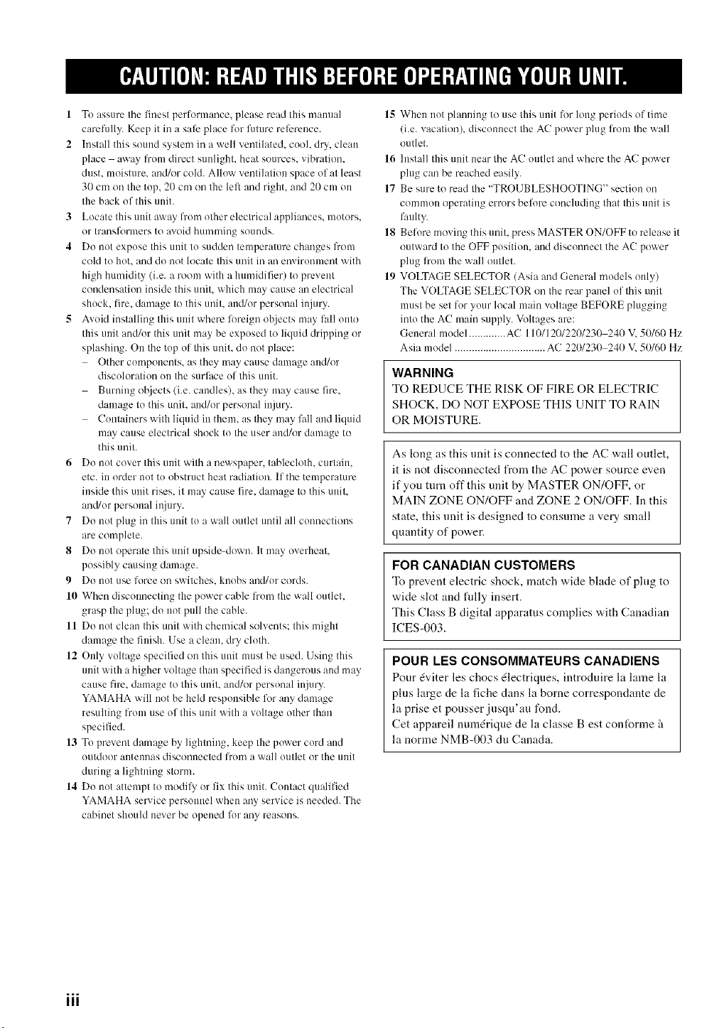
WARNING
TO REDUCE THE RISK OF FIRE OR ELECTRIC
SHOCK, DO NOT EXPOSE THIS UNIT TO RAIN
OR MOISTURE.
As long as this unit is connected to the AC wall outlet,
it is not disconnected from the AC power source even
if you turn off this unit by MASTER ON/OFF, or
MAIN ZONE ON/OFF and ZONE 2 ON/OFF. In this
state, this unit is designed to consume a very small
quantity of power.
FOR CANADIAN CUSTOMERS
To prevent electric shock, match wide blade of plug to
wide slot and fully insert.
This Class B digital apparatus complies with Canadian
ICES-003.
POUR LES CONSOMMATEURS CANADIENS
Pour _viter les chocs _lectriques, introduire la lame la
plus large de la fiche dans la borne correspondante de
la prise et pousser jusqu'an fond.
Cet appareil numdrique de la classe Best conforme _
la norme NMB-003 du Canada.
iii
FEATURES ............................................................. 2
SUPPLIED ACCESSORIES ................................. 2
CONTROLS AND FUNCTIONS ......................... 3
Front panel ................................................................. 3
Front panel display .................................................... 5
Rear panel .................................................................. 6
Remote control ........................................................... 7
Zone 2 remote control ................................................ 9
Installing batteries in the remote controls ................ 11
Using the remote controls ........................................ 11
CONNECTIONS .................................................. 12
Comlecting speakers ................................................ 12
Comaecting audio and video components ................ 13
Cormecting the AM and FM antennas ..................... 14
Comlecting the power supply cord .......................... 16
Turning on and off this unit ..................................... 17
PLAYING AND RECORDING .......................... 18
Playing a source ....................................................... 18
Adjusting the tonal quality ....................................... 20
Recording a sottrce .................................................. 21
Using the sleep timer ............................................... 22
Muting the sound output .......................................... 23
FM/AM T[ NING ................................................. 24
Automatic tuning ..................................................... 24
Manual ttming .......................................................... 25
Automatic preset tuning ........................................... 26
Manual preset ttming ............................................... 28
Selecting preset stations ........................................... 29
Exchanging preset stations ...................................... 29
XM SATELLITE RADIO T[ NING .................. 30
\_qlat is XM Satellite Radio'? ................................... 30
XM Satellite Radio connections .............................. 30
XM Satellite Radio functions .................................. 31
Activating XM Satellite Radio ................................ 33
Basic XM Satellite Radio operations ....................... 34
XM Satellite Radio search modes ............................ 35
Setting XM Satellite Radio preset channels ............ 37
ADVANCED SETIP ............................................ 39
Changing the ADVANCED SETUP menu
parameters ........................................................... 39
Switching the remote control ID ............................. 40
ZONE 2 .................................................................. 41
Connecting the Zone 2 components ........................ 41
Controlling Zone 2 ................................................... 42
REMOTE CONTROL FEAT[ RES ................... 43
Control area ............................................................. 43
Controlling other components ................................. 44
Setting remote control codes ................................... 45
TROUBLESHOOTING ....................................... 46
SPECIFICATIONS ............................................... 49
Built-in 2-channel power amplifier
• Minimum RMS output power
i00 W + 100 W (8 _Q), 0.019% THD, 20 Hz to 20 kHz
• Highly dynamic power, low impedance drive
capability
Sophisticated AM/FM tuner
• 40-station random access preset tuning
• Automatic preset tuning
• Preset station exchanging capability
• Radio Data System tuning capability
(Europe model only)
XM Satellite Radio
(U.S.A. model only)
• XM Satellite Radio tuning capability using the XM
Connect-and-Play TM digital antenna accessory (sold
separately)
Other features
• PURE DIRECT button used to reproduce the purest
source sound
• CD DIRECT AMP button used to reproduce the purest
CD sound
• RE(7 OUT selector independent of input source
selection
• Continuously variable loudness control
• Sleep timer
• Remote control capability
• Zone 2 remote control supplied
• Zone 2 custom installation facility
• -"4"-indicates a tip for your operation.
• Some operations can be peribrmed by using either the buttons on the front panel of this unit or those on the remote controls. In case
the button names differ between this unit and the remote controls, the names of the bnttons on the remote controls are given in
parentheses.
• In case the buttons on the remote control and the Zone 2 remote control have certain ftmctions in common, the illustrations of the
buttons on the remote control are used for explanation throughont the manual.
• This manual is printed prior to production. Design and specifications are sul_ject to change in part as a result of improvements, etc. In
case of differences between the manual and the product, the product has priority.
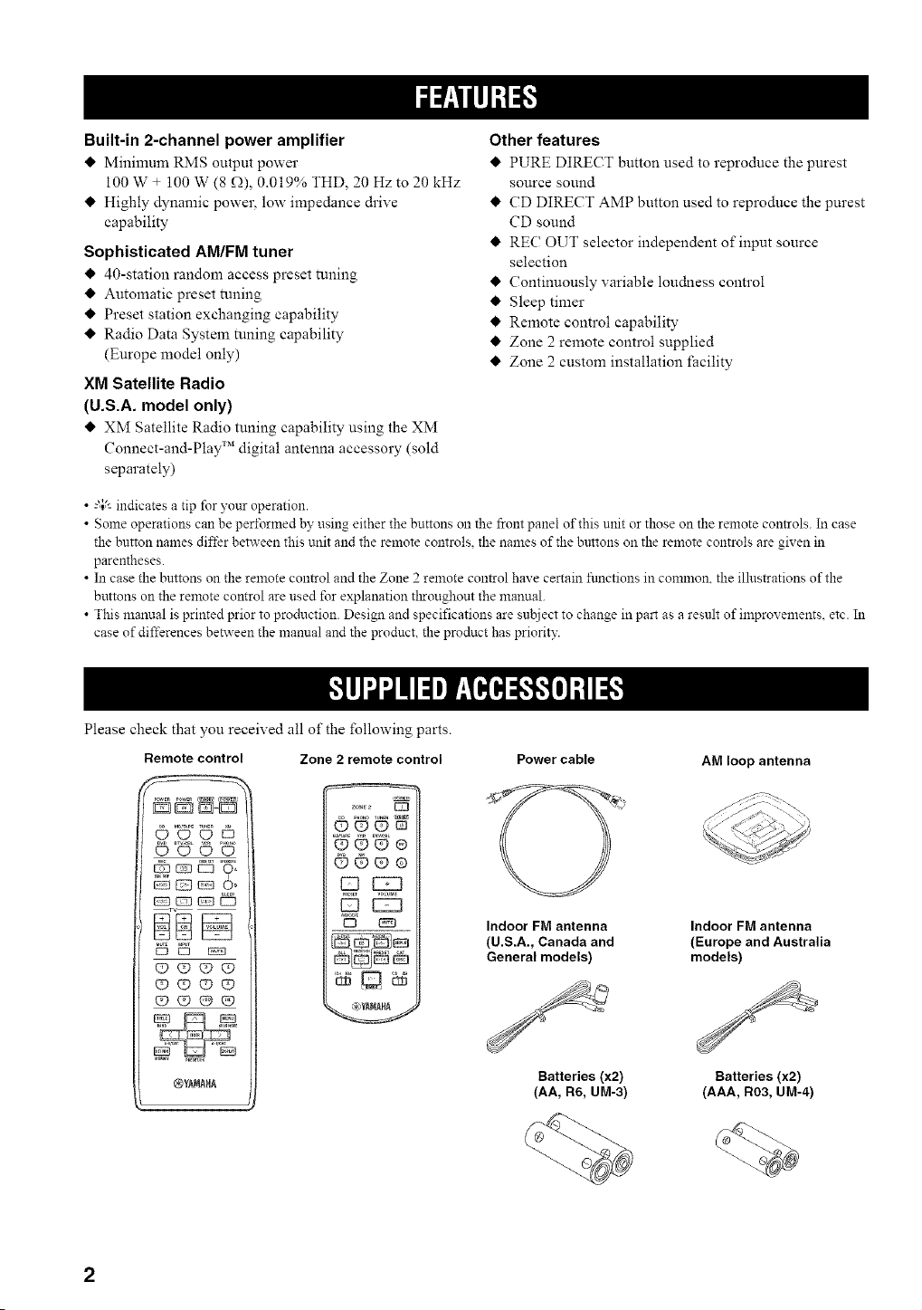
Please check that you received all of the following parts.
Remote control Zone 2 remote control Power cable
©=UU E5
0000
1i%
[23 I23
(!) (9 Q9 _
(9 @ (29 (9
®%'AMA£A
.6.Go_ e
@@®e
i:z3
D [_3
'_
Indoor FM antenna
(U.S.A., Canada and
General models)
Batteries (x2)
(AA, Rd, UM-3)
AM loop antenna
Indoor FM antenna
(Europe and Australia
models)
Batteries (x2)
(AAA, R03, UM-4)
i i i /
f
,, \ )
W "W..... "<...... 'LW"
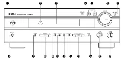
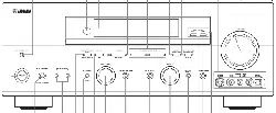
(U.S.A. model)
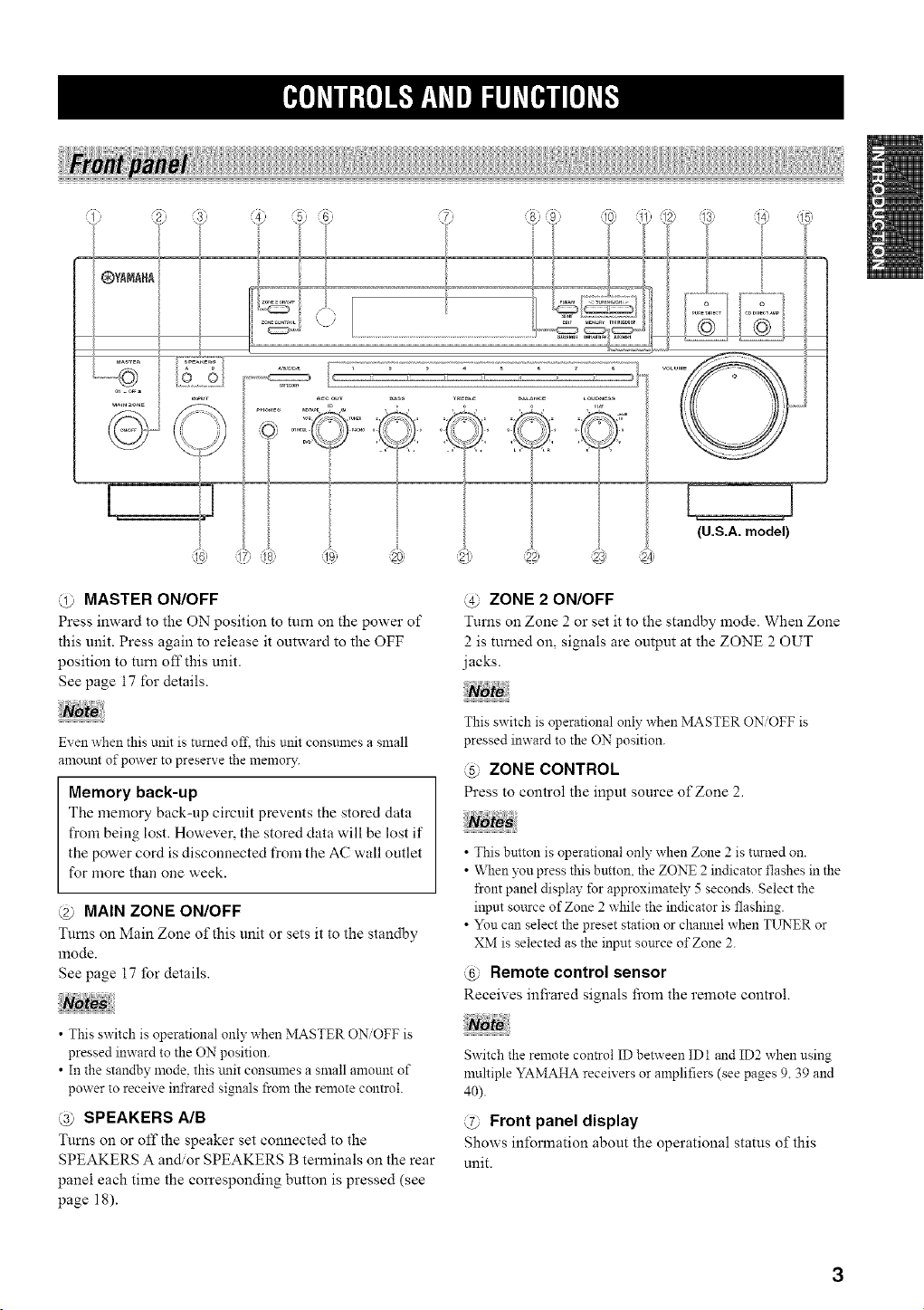
@ MASTER ON/OFF
Press inward to the ON position to turn on the power of
this unit. Press again to release it outward to the OFF
position to turn off this unit.
See page 17 for details.
@ ZONE 2 ON/OFF
Turns on Zone 2 or set it to the standby mode. When Zone
2 is turned on, signals are output at the ZONE 2 OUT
jacks.
Even when this unit is turned 0fl_this unit constnnes a small
amount of power to preserve the memo13".
Memory back-up
The memory back-up circuit prevents the stored data
from being lost. However, the stored data will be lost if
the power cord is disconnected from the AC wall outlet
for more than one week.
@ MAIN ZONE ON/OFF
Turns on Main Zone of this unit or sets it to the standby
mode.
See page 17 for details.
This switch is operational only when MASTER ON/OFF is
pressed inward to the ON position.
@ ZONE CONTROL
Press to control the input source of Zone 2.
• This button is operational only when Zone 2 is turned on.
• When you press this button, the ZONE 2 indicator flashes in the
front panel display for approximately 5 seconds. Select the
inpm sottrce of Zone 2 while the indicator is flashing.
• You can select the preset station or channel when TLrNER or
XM is selected as the input source of Zone 2.
@ Remote control sensor
Receives infrared signals from the remote control.
• This switch is operational only when MASTER ON/OFF is
pressed inward to the ON position.
• In the standby mode. this trait consmnes a small amount of
power to receive infrared signals from the remote control.
@ SPEAKERS A/B
Turns on or off the speaker set connected to the
SPEAKERS A and/or SPEAKERS B terminals on the rear
panel each time the corresponding button is pressed (see
page 18).
Switch the remote control ID between ID1 and ID2 when using
multiple YAMAHA receivers or amplifiers (see pages 9, 39 and
40).
@ Front panel display
Shows information about the operational status of this
unit.
K_e]dlll;{e]_*JF_qdlel_lld[e_Jl[e]d_
@ EDIT, SEARCH MODE
Exchanges the assignment of two preset stations with each
other when TUNER is selected as the input source (see
page 29).
Switches between search modes when XM is selected as
the input source (see page 33).
@ FM/AM, XM ANT (ANTENNA)
Switches the reception band between AM and FM when
TUNER is selected as the input source (see page 24).
Shows the reception level of the XM Connect-and-Play
digital antenna (sold separately) when XM is selected as
the input source (see page 31).
@ TUNING/CH <_ / _>
Selects the tuning frequency when TUNER is selected as
the input source (see page 24).
Searches for a radio channel or selects the preset channel
number when XM is selected as the input source (see page
31).
@ TUN (TUNING) MODE/DISP (DISPLAY)
Switches the tuning mode between automatic (the AUTO
indicator turns on as a result) and manual (the AUTO
indicator turns offas a result) when TUNER is selected as
the input source.
Switches the XM Satellite Radio infommtion shown in the
front panel display between channel number name,
category and artist name/song title when XM is selected as
the input source (see page 34).
@ MEMORY
Stores a station in the system memory (see page 28).
Sets this unit to the automatic preset tuning mode (see
page 26).
Stores a radio channel in the system memory when XM is
selected as the input source (see page 37).
@ PURE DIRECT and indicator
Allows you to listen to a source in the purest possible
sound. The indicator above it lights up when this function
is turned on.
See page 20 fbr details.
@ CD DIRECT AMP and indicator
Allows you to listen to a CD source in the purest possible
sound. The indicator above it lights up and the front panel
display turns offwhen this function is turned on.
See page 20 fbr details.
@ VOLUME
Increases or decreases the sound output level.
This does not affect the OUT (REC) level.
@ INPUT selector
Selects the input source you want to listen to or watch.
@ AIBICIDIE, CATEGORY
Selects the preset station group (A to E) when TUNER is
selected as the input source (see page 27).
Switches between channel categories or selects the preset
channel group when XM is selected as the input source
(see page 35).
@ PHONES jack
Outputs audio lbr private listening with your headphones.
Press SPEAKER AiB so that the SP AiB indicators Run off
be_\_re you connect your hea@hones to the PHONES jack.
@ REC OUT selector
Selects a source lbz"recording to the MD recorder or the
tape deck independently of the INPUT selector setting,
allowing you to record the selected source while listening
to another source (see page 21).
BASS
Increases or decreases the low frequency response. The 0
position produces a flat response (see page 20).
@ TREBLE
Increases or decreases the high frequency response. The 0
position produces a flat response (see page 20).
@ BALANCE
Adjusts the sound output balance of the left and right
speakers to compensate for sound imbalances caused by
speaker locations or listening room conditions (see page
20).
@ LOUDNESS
Retains a full tonal range at any volume level to
compensate for the human ears' loss of sensitivity to high
and low-frequency ranges at a low volume level (see page
20).
@ Preset station/channel number buttons
(1 to 8)
Selects the preset station channel number (1 to 8) directly
when TUNER or XM is selected as the input source (see
page 29).
The XM Satellite Radio features (XM ANT, CH. SEARCH
MODE, DISP, CATEGORY, MEMORY and the preset chamlel
number buttons) are only applicable to the U.S.A. model and are
operational only when XM is selected as the input source. For
details, see "XM SATELLITE RADIO TLLNING" on page 30.
_e]dll;{e]J_'f_qdlel_lJd[e_Jl[e]d[,
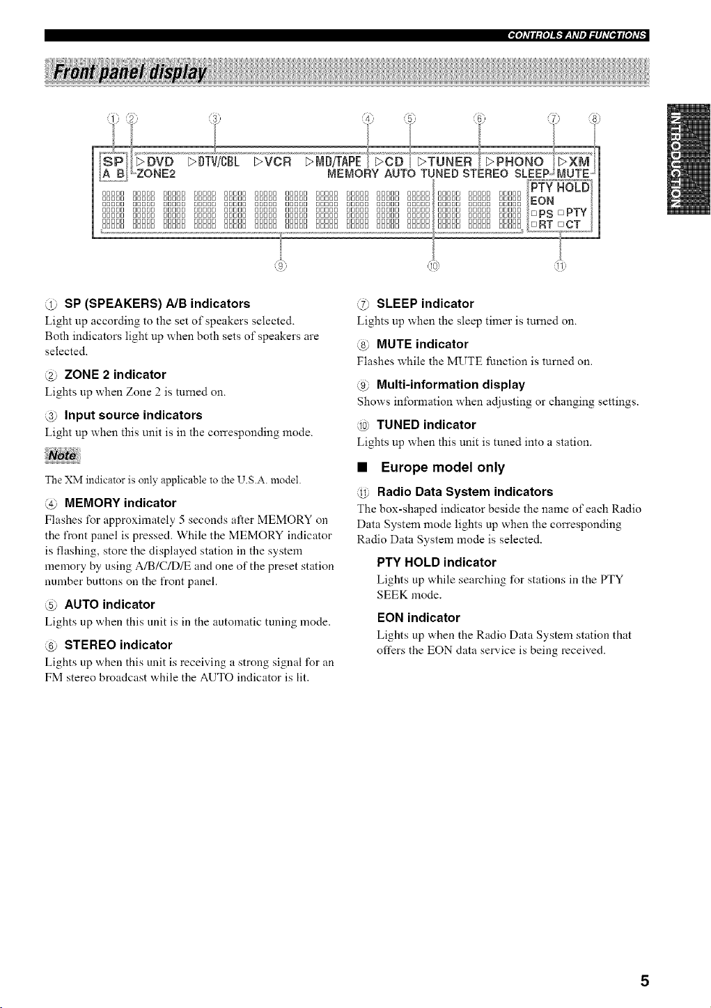
@ SP (SPEAKERS) A/B indicators
Light up according to the set of speakers selected.
Both indicators light up when both sets of speakers are
selected.
@ ZONE 2 indicator
Lights up when Zone 2 is turned on.
@ Input source indicators
Light up when this unit is in the corresponding mode.
The XM indicator is only applicable to the U.S.A. model.
@ MEMORY indicator
Flashes for approximately 5 seconds after MEMORY on
the front panel is pressed. While the MEMORY indicator
is flashing, store the displayed station in the system
memory by using A/B/C/D/E and one of the preset station
number buttons on the front panel.
@ AUTO indicator
Lights up when this nnit is in the automatic tuning mode.
@ STEREO indicator
Lights up ,a,hen this unit is receiving a strong signal for an
FM stereo broadcast while the AUTO indicator is lit.
@ SLEEP indicator
Lights up when the sleep timer is turned on.
@ MUTE indicator
Flashes while the MUTE function is turned on.
@ Multi-information display
Shows information when adjusting or changing settings.
@ TUNED indicator
Lights up when this unit is tuned into a station.
• Europe model only
@ Radio Data System indicators
The box-shaped indicator beside the name of each Radio
Data System mode lights up when the corresponding
Radio Data System mode is selected.
PTY HOLD indicator
Lights up while searching for stations in the PTY
SEEK mode.
EON indicator
Lights up when the Radio Data System station that
offers the EON data service is being received.
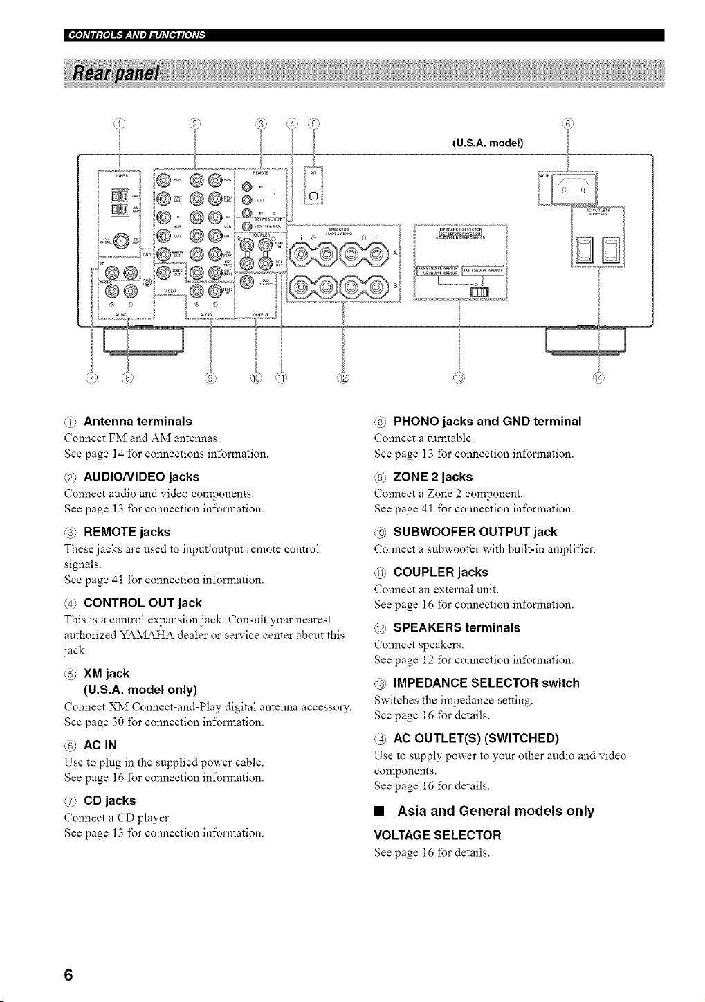
@ Antenna terminals
Connect FM and AM antennas.
See page 14 for connections information.
@ AUDIO/VIDEO jacks
Connect audio and video components.
See page 13 for connection information.
@ REMOTE jacks
These jacks are used to input output remote control
signals.
See page 41 for connection information.
@ CONTROL OUT jack
This is a control expansion jack. Consult your nearest
authorized YAMAHA dealer or service center about this
jack.
@ XM jack
(U.S.A. model only)
Connect XM Connect-and-Play digital antenna accessol T.
See page 30 for connection information.
@ AC IN
Use to plug in the supplied power cable.
See page 16 for connection information.
@ CD jacks
Connect a CD player.
See page 13 for connection information.
@ PHONO jacks and GND terminal
Connect a turntable.
See page 13 for connection information.
@ ZONE 2 jacks
Connect a Zone 2 component.
See page 41 for connection information.
@ SUBWOOFER OUTPUT jack
Connect a subwoofer with built-in amplifier.
@ COUPLER jacks
Connect an external unit.
See page 16 for connection information.
@ SPEAKERS terminals
Connect speakers.
See page 12 for connection information.
@ IMPEDANCE SELECTOR switch
Switches the impedance setting.
See page 16 for details.
@ AC OUTLET(S) (SWITCHED)
Use to supply power to your other audio and video
components.
See page 16 for details.
• Asia and General models only
VOLTAGE SELECTOR
See page 16 for details.
_O]_TII;{O]Jk'JF:hqlI_IJ_T[elI[O]_Tg
This section describes the function of each button on the
remote control used to control this unit or other
components made by YAMAHA or other manufacturers.
The functions of the buttons used to control your other
audio and video components are the same as those of the
con'esponding buttons on those components. Refer to
those components' instruction manuals for details. To
operate other components using this remote control, see
"REMOTE CONTROL FEATURES" on page 43.
0}
..............:?;
............:g;,
o<9)
......_10_
,,<}
.........84"_
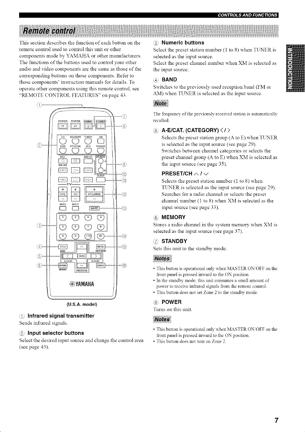
@ Infrared signal transmitter
Sends infrared signals.
@ Input selector buttons
Select the desired input source and change the control area
(see page 43).
@ Numeric buttons
Select the preset station number (I to 8) when TUNER is
selected as the input source.
Select the preset channel number when XM is selected as
the input source.
@ BAND
Switches to the previously used reception band (FM or
AM) when TUNER is selected as the input source.
The frequency of the previously received station is autoznatically
recalled.
@ A-E/CAT. (CATEGORY) < / >
Selects the preset station group (A to E) when TUNER
is selected as the input source (see page 29).
Switches between channel categories or selects the
preset channel group (A to E) when XM is selected as
the input source (see page 35).
PRESET/CH ,t", / v
Selects the preset station number (1 to 8) when
TI__ER is selected as the input source (see page 29).
Searches for a radio channel or selects the preset
channel number (1 to 8) when XM is selected as the
input source (see page 33).
@ MEMORY
Stores a radio channel in the system memory when XM is
selected as the input source (see page 37).
@ STANDBY
Sets this unit to the standby mode.
• This button is operational only when MASTER ON/OFF on the
front panel is pressed inward to the ON position.
• In the standby mode, this trait consnmes a small amount of
power to receive infrared signals from the remote control.
• This bntton does not set Zone 2 to the standby mode.
@ POWER
Turns on this unit.
• This button is operational only when MASTER ONOFF on the
front panel is pressed inward to the ON position.
• This button does not turn on Zone 2.
@ SPEAKERS A/B
Turns on or off the set of speakers connected to the
SPEAKERS A and, or SPEAKERS B terminals on the rear
panel of this unit when the con'esponding button is
pressed each time.
@ CODE SET
Use to set up remote control codes (see page 45).
@ SLEEP
Sets the sleep timer.
@ VOLUME +/-
Increases or decreases the sound output level.
• This does not affect the OUT (RE(?) level.
• When you press VOLUME +_ to control the sound output
level of this tulit, VOLUME on the *'rontpanel rotates.
@ MUTE
Mutes the sound output. Press again to restore the sound
output to the previous volume level (see page 23).
The sound output to Zone 2 is not muted.
@ ENT. (ENTER)
Confirms an entered channel number during the Direct
Number Access mode when XM is selected as the input
source.
@ SRCH (SEARCH) MODE
Switches between the XM Satellite Radio search modes
(see page 35) when XM is selected as the input source.
@ DISPLAY
Switches the XM Satellite Radio infomlation shown in the
front panel display between channel number name,
catego W and artist name/song title when XM is selected as
the input source.
The XM Satellite Radio features (XM, SRCH MODE DISPLAY,
A-E/CAT. < / >, PRESETiCH/', / ",/, MEMORY and ENT.) are
only applicable to the U.S.A. model and are operational only
when XM is selected as the inpm source. For details, see "XM
SATELLITE RADIO TUNING" on page 30.

e..re]dll;{e]J_]F_qdlel_lJd[e_Jl[e]d[,
This section describes the function of each button on the
Zone 2 remote control used to control Zone 2. You can
also use the Zone 2 remote control to control the XM
Satellite Radio features and YAMAHA CD players.
0)
......
'?4>,,,,,,
:POWER
ZON E 2
VOLUME ............
_'B/C/D/E
(U.S.A. model)
.............{a:
.........<9)
..........40:
@ Infrared signal transmitter
Sends infrared signals.
@ Input selector/numeric buttons
Select the desired input source of Zone 2.
Enter a channel number or preset channel number when
XM is selected as the input source.
You nmst press and hold NUMBER before you press an?*of these
buttons to enter nnmbers.
@ PRESET/', / v
Selects the preset station number (l to 8) when TUNER is
selected as the input source.
@ AIBICIDIE
Selects the preset station group (A to E) when TUNER is
selected as the input source.
@ XM Satellite Radio control buttons
Controls the XM Satellite Radio features when the
CDiXM switch is slid to the XM position.
A-E/CAT. (CATEGORY) <_ / c>
Switches between channel categories or selects the
preset channel group (A to E) when XM is selected as
the input source.
PRESET/CH A / V
Searches for a radio channel or selects the preset
channel number (1 to 8) when XM is selected as the
input source.
ALL
Selects the All Channel Search mode.
PRESET
Selects the Preset Search mode.
CAT. (CATEGORY)
Selects the Category Search mode.
@ IDI/ID2 switch
Switches the remote control ID between IDI and ID2 (see
page 40).
@ POWER
Turns on Zone 2.
@ STANDBY
Sets Zone 2 to the standby mode.
@ ENT (ENTER)
Confirms an entered channel number during the Direct
Number Access mode when XM is selected as the input
source.
@ VOLUME +/-
Increases or decreases the sound output level of Zone 2.
This does not affect the OUT (REC) level.
K_e]dllg{e]_]F_Ydlel_lld[_Jl[e]d_
@ MUTE
Mutes the sound output to Zone 2. Press again to restore
the sound output to the previous volume level.
@ DISPLAY
Switches the XM Satellite Radio information displayed in
the front panel display between channel number.name,
catego W and artist name/song title when XM is selected as
the input source.
@ CD/XM switch
Switches the function of the control buttons numbered @,
@ and @ between controlling YAMAHA CD players and
controlling the XM Satellite Radio features.
@ NUMBER
Press and hold before you press the input selector.numeric
buttons to enter numbers to control the XM Satellite Radio
features.
The XM Satellite Radio features (XM, ENT. DISPLAY and the
XM Satellite Radio control buttons) are only applicable to the
U.S.A. model and are operational only when XM is selected as
the input source and the CDiXM switch is slid to the XM
position. For details, see "XM SATELLITE RADIO TL_rNING"
on page 30.
10

• Notes on batteries
(hange all of the batteries if the operation range of the remnte controls decreases.
Use AA. R6 UM-3 batteries for the remote control and AAA R03 UM-4 batteries for the Zone 2 remote control.
Make sure that the polarities are correct. See the illustration inside the batte D" compartment of each remote control.
Remove the batteries if the remote controls are not used for an extended period of time.
Do not use old batteries together with new ones.
Do not use different t3_pesof batteries (such as alkaline and manganese batteries) together. Read the packaging carefully as these
different types of batteries may have the same shape and color.
• We strongly recommend using alkaline batteries.
• If the batteries have leaked, dispose of them immediately. Avoid touching the leaked material or letting it come into contact with
clothing, etc. Clean the battery compartment thoroughly before installing new batteries.
• Do not throw away batteries with general house waste: dispose of them correctly in accordance with your local regulations.
Remote control Zone 2 remote control
1%q{a
1 Open the battery compartment cover.
2
3 Close the cover back.
Insert the supplied batteries in each remote
control according to the polarity markings (+
and -) on the inside of the battery
compartment.
The remote controls transmit a directional infrared beam.
Be sure to aim the remote controls directly at the remote control sensor on the front panel of this unit or on the infrared
signal receiver in Zone 2 during operation.
Approximately 6 m (19.7 ft)
• Handling the remote controls
• The area between the remote controls and this unit (or the
in_ared signal receiver in Zone 2) mnst be clear of large
obstacles.
• Do not spill water or other liquids on the remote controls.
• Do not drop the remote controls.
• Do not leave or store the remote controls in the following types
of conditions:
places of high hulnidit3: such as near a bath
places of high temperature, such as near a heater or a stove
places of extremely low temperatures
dusty places
• Do not expose the remote control sensor to strong lighting, in
particular, an inverter type fluorescent lamp; otherwise, the
remote controls may not work properly. If necessar._: position
this unit away from direct lighting.
11
Be sure to connect the left channel (L), right channel (R), '%" (red) and .... (black) properly. If the connections are faulty,
no sound will be heard from the speakers, and if the polarity of the speaker connections is incon'ect, the sound will be
unnatural and lack bass.
• Before connecting the speakers, make sure that the power of this unit is turned off.
• Do not let the bare speaker wires touch each other or do not let them touch any metal part of this unit. This could
damage this unit and.or the speakers.
• Use magnetically shielded speakers. If this type of speakers still creates the interference with the monitor, place the
speakers away from the monitor.
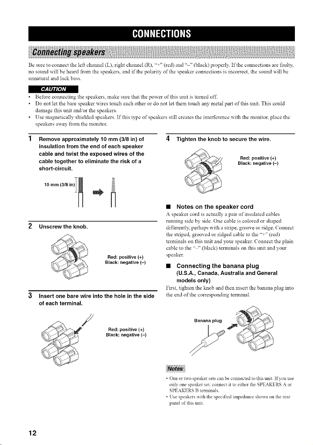
Remove approximately 10 mm (3/8 in) of
insulation from the end of each speaker
cable and twist the exposed wires of the
cable together to eliminate the risk of a
short-circuit.
Unscrew the knob.
Red: positive (+)
Black: negative (-)
3 Insert one bare wire into the hole in the side
of each terminal.
4 Tighten the knob to secure the wire.
Red: positive (+)
Black: negative (-)
• Notes on the speaker cord
A speaker cord is actually a pair of insulated cables
running side by side. One cable is colored or shaped
differently, perhaps with a stripe, groove or ridge. Connect
the striped, grooved or ridged cable to the "+" (red)
terminals on this unit and your speaker. Connect the plain
cable to the .... (black) terminals on this unit and your
speaker.
• Connecting the banana plug
(U.S.A., Canada, Australia and General
models only)
First, tighten the knob and then insert the banana plug into
the end of the corresponding terminal.
/
Red: positive (+)
Black: negative (-)
Banana plug
• One or two speaker sets can be connected to this unit. If you use
only one speaker set. connect it to either the SPEAKERS A or
SPEAKERS B terminals.
• Use speakers with the specified impedance shown on the rear
panel of this unit.
12
[_:lIJl_o1Av|
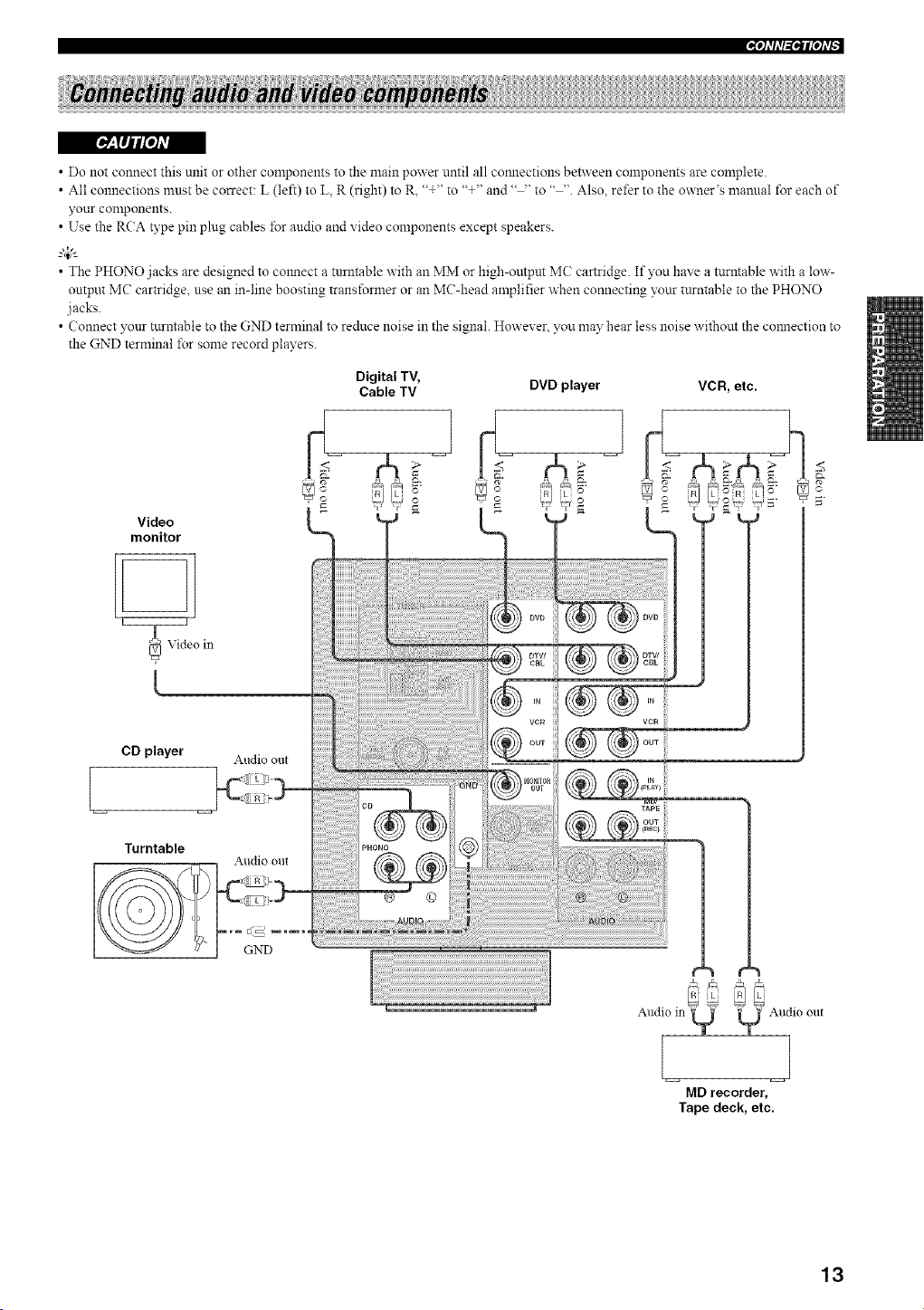
• Do not connect this unit or other components to the main power until all comlections between components are complete
• All connections must be correct: L (left) to L, R (right) to R, "+'" to "+'" and .... to " " Also, rd'er to the owner's manual for each of
your components
• Use the RCA type pin plug cables for audio and video components except speakers
--'4:--
• The PHONO jacks are designed to colmect a turntable with an MM or high-outpnt MC cartridge If you have a turntable with a low-
output MC car_idge, use an in-line boosting transformer or an MC-head amplifier when connecting your turntable to the PHONO
jacks
• Connect your turntable to the GND terminal to reduce noise in the signal However, you may hear less noise without the colmection to
the GND terminal %r some record players
Video
monitor
Digital TV,
Cable TV DVD player VCR, etc.
C
CD player Audio out
Turntable
GND
€= ,_
Audio in Q _ _ Audio out
L
MD recorder,
Tape deck, etc.
13
I_"tflfl_qlPh'F
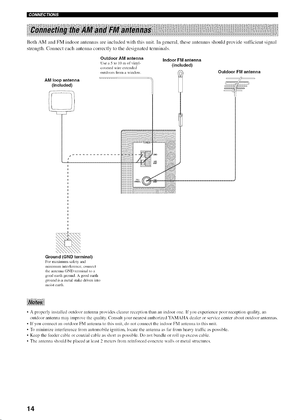
Both AM and FM indoor antennas are included with this unit. In general, these antennas should provide sufficient signal
strength. Connect each antenna correctly to the designated terminals.
AM loop antenna
(included)
Outdoor AM antenna
Use a5 to lO m ot _inyl-
cm ercd wire extended
Otltdoors ]ronl a Willdow.
Indoor FM antenna
(included)
Outdoor FM antenna
:27;
Ground (GND terminal)
For maximmn saicty _uld
tllillilllUlll interlcrence, connect
the antenna GND tcrminal to a
good earth ground. A good earth
ground is a metal stake drivcn into
nloist earth,
• A properly installed outdoor atttenna provides clearer reception than an indoor one. If you experience poor reception quality, an
outdoor antenna may improve the quality. Consult your nearest authorized YAMAHA dealer or service center about outdoor antennas.
• If you connect an outdoor FM antenna to this unit. do not connect the indoor FM antenna to this unit.
• To minimize interllerence from automobile ignition, locate the antenna as li_r from heavy traffic as possible.
• Keep the li:eder cane or coaxial cable as short as possible. Do not bundle or roll up excess cable.
• The antenna should be placed at least 2 meters h'om reinlk)rced concrete walls or metal structures.
14
1
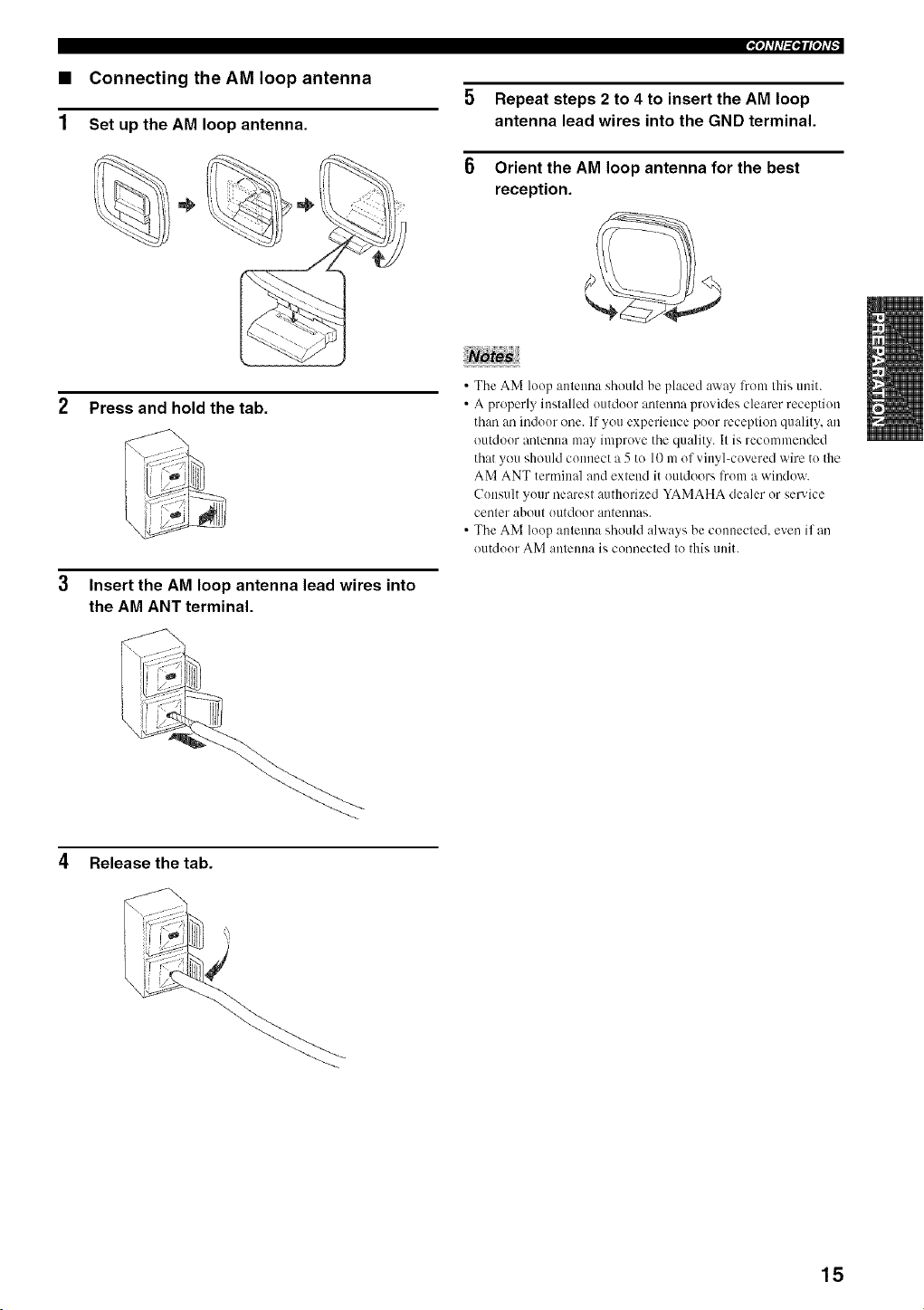
Connecting the AM loop antenna
Set up the AM loop antenna.
Press and hold the tab.
3 Insert the AM loop antenna lead wires into
the AM ANT terminal.
5 Repeat steps 2 to 4 to insert the AM loop
antenna lead wires into the GND terminal.
6 Orient the AM loop antenna for the best
reception.
• The AM loup antenna should be placed away l?om this unit.
• A properly installed uutdour antenna provides clearer receptiuu
than an indour one. If you experience puor reception quality, an
outdour antenna may improve the quality. It is recommended
that you should connect a 5 to 10 m of vinyl-covered wire to the
AM ANT terminal and extend it outdoors l?um a window.
Cuusult your nearest authorized YAMAHA dealer or service
center about uutdoor antennas.
• The AM luop antenna should always be cunuected, even if an
outdour AM antenna is connected to this unit.
4 Release the tab.
15
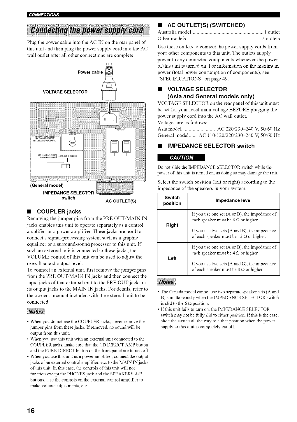
|'_'tfll'l_ql['h'_
Plug the power cable into the AC IN on the rear panel of
this unit and then plug the power supply cord into the AC
wall outlet after all other connections are complete.
Power cable _
VOLTAGE SELECTOR "[_
• AC OUTLET(S) (SWITCHED)
Australia model ...................................................... 1 outlet
Other models ....................................................... 2 outlets
Use these outlets to connect the power supply cords from
your other components to this unit. The outlets supply
power to any connected components whenever the power
of this unit is mined on. For information on the maximum
power (total power consumption of components), see
"SPECIFICATIONS" on page 49.
• VOLTAGE SELECTOR
(Asia and General models only)
VOLTAGE SELECTOR on the rear panel of this unit must
be set for your local main voltage BEFORE plugging the
power supply cord into the AC wall outlet.
Voltages are as follows:
Asia model ......................... AC 220/230 240 V, 50/60 Hz
General model ...... AC 110/120/220/230 240 V, 50/60 Hz
• IMPEDANCE SELECTOR switch
r__,llji/o/Avl
(General model)
IMPEDANCE SELECTOR
switch
AC OUTLET(S)
• COUPLER jacks
Removing the jumper pins from the PILE OUT MAIN IN
jacks enables this unit to operate separately as a control
amplifier or a power amplifier. These jacks are used to
connect a signal-processing system such as a graphic
equalizer or a surround-sound processor to this unit. If
such an external unit is connected to these jacks, the
VOLUME control of this unit can be used to adjust the
overall sound output level.
To connect an external unit, first remove the jumper pins
from the PRE OUT/MAIN IN jacks and then connect the
input jacks of that extemal unit to the PRE OUT jacks or
its output jacks to the MAIN" IN jacks. For details, refer to
the owner's manual included with the external unit to be
connected.
• When you do not use the COUPLER jacks, never remove the
jmnper pins from these jacks. If removed, no sotmd will be
output from this trait.
• When you use this unit with an external unit connected to the
COUPLER jacks, make sure that the CD DIRECT AMP button
and the PURE DIRECT button on the front panel are turned off.
• When you use this unit as a power amplifier, connect the output
jacks of an external control amplifier, etc. to the MAIN IN jacks
of this unit. In this case, the controls of this unit will not
fimction except the PHONES jack and the SPEAKERS AiB
buttons. Use the controls on the external control amplifier to
make volume ac[iustments, etc.
Do not slide the IMPEDANCE SELECTOR switch while the
power of this unit is turned on, as doing so may damage the trait.
Select the switch position (left or right) according to the
impedance of the speakers in your system.
Switch
position Impedance level
If you use one set (A or B), the impedance of
each speaker must be 6 _ or higher.
Right
If you use two sets (A and B), the impedance
of each speaker must be 12 _ or higher.
If you use one set (A or B), the impedance of
each speaker must be 4 _ or higher.
Left
If you use two sets (A and B), the impedance
of each speaker must be 8 f_ or higher.
• The Canada model cannot use two separate speaker sets (A and
B) sinmltaneously when the IMPEDAN(E SELE(TOR switch
is slid to the 6 f_ position.
• If this unit fails to ttml on, the IMPEDANCE SELECTOR
switch may not be fnlly slid to either position. If this is the case,
slide the switch all the way to either position when the power
supply to this unit is completely cut off.
16
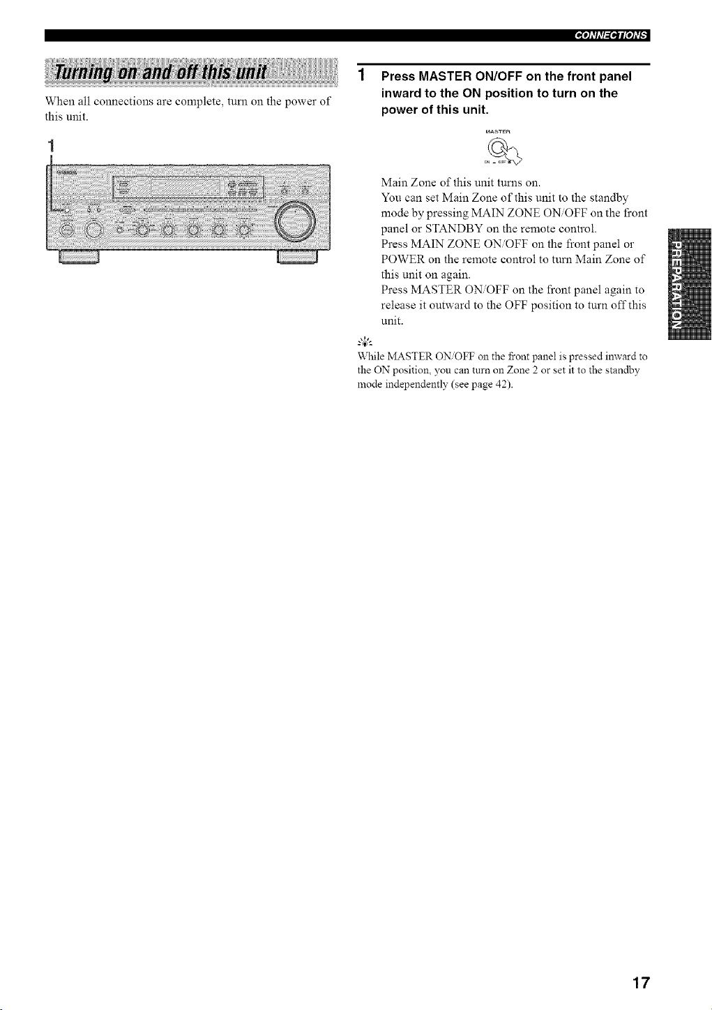
When all connections are complete, turn on the power of
this unit.
1 Press MASTER ON/OFF on the front panel
inward to the ON position to turn on the
power of this unit.
MAS_R
Main Zone of this unit turns on.
You can set Main Zone of this unit to the standby
mode by pressing MAIN ZONE ON/OFF on the l_cont
panel or STANDBY on the remote control.
Press MAIN ZONE ON/OFF on the front panel or
POWER on the remote control to turn Main Zone of
this unit on again.
Press MASTER ON/OFF on the front panel again to
release it outward to the OFF position to turn off this
unit.
g4_'--
While MASTER ON/OFF on the front panel is pressed inward to
the ON position, you can turn on Zone 2 or set it to the standby
mode independently (see page 42).
17
[_': TIj//oJAv|
Extreme caution should be exercised when you play back CDs encoded in DTS.
If you play back a CD encoded in DTS on a DTS-incompatible CD player, you will only hear some unwanted noise that may damage
your speakers. Check whether your CD player supports CDs encoded in DTS. Also. check the sound output level of your CD player
before you play back a CD encoded in DTS.
2
I
6 1 5
m
1-
-2
=4
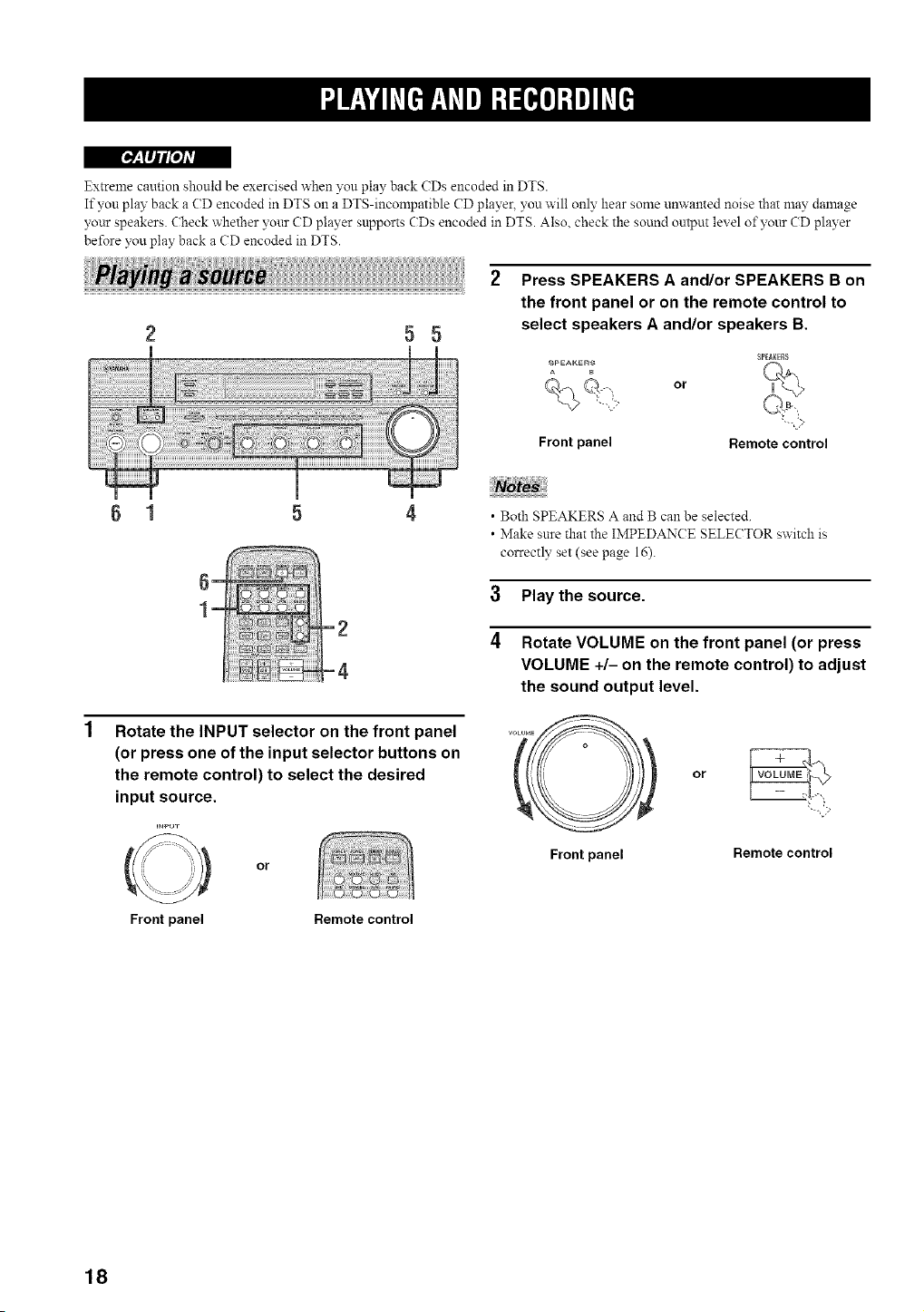
Press SPEAKERS A and/or SPEAKERS B on
the front panel or on the remote control to
select speakers A and/or speakers B.
8P[AgEg8
SPEAKERS
A B
or
Front panel Remote control
NoW
• Both SPEAKERS A and B can be selected.
• Make sure that the IMPEDANCE SELECTOR switch is
correctly set (see page 16).
3 Play the source.
4 Rotate VOLUME on the front panel (or press
VOLUME +/- on the remote control) to adjust
the sound output level.
Rotate the INPUT selector on the front panel
(or press one of the input selector buttons on
the remote control) to select the desired
input source.
=NPUT
O
Front panel
or
Remote control
Front panel
or
Remote control
18
'Jf_,|¥hV[ef_,1_VeJ=l_[esre]=te]hV[J
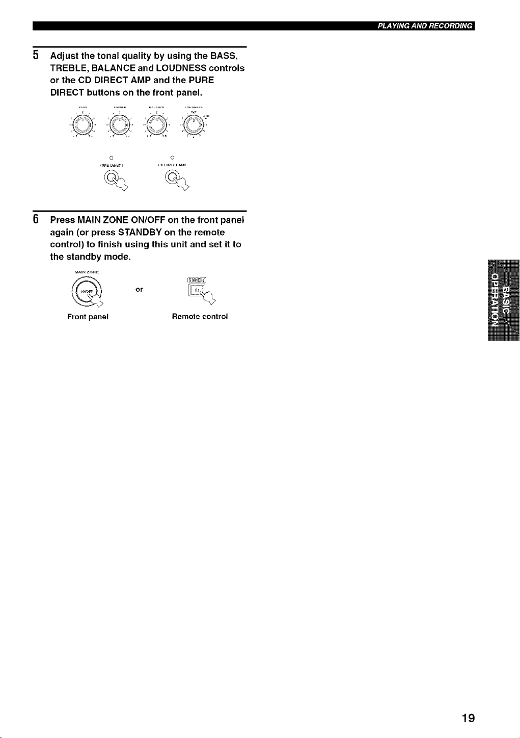
Adjust the tonal quality by using the BASS,
TREBLE, BALANCE and LOUDNESS controls
or the CD DIRECT AMP and the PURE
DIRECT buttons on the front panel.
i©i8
© ©
P_E _IRECt CDD_ECT AMP
Press MAIN ZONE ON/OFF on the front panel
again (or press STANDBY on the remote
control) to finish using this unit and set it to
the standby mode.
MAIN ZONE
Frontpanel
or
Remote control
19
il'.JIF:lgdld[e]F:Idlel_l:[_e]_te]ld[J
• Adjusting the BALANCE control
Adjusts the sound output balance of the left and right
speakers to compensate lbr sound imbalance caused by
speaker locations or listening room conditions.
r__,lljifl'olAVl
gALAHCE
• Using the CD DIRECT AMP button
Routes input signals from your CD player directly to the
specially built-in amplifier for the CD player. As a result,
the input signals bypass the INPUT selector and the
BASS, TREBLE, BALANCE and LOUDNESS controls
and then sent to the power amplifier, thus eliminating any
alterations to the CD signals and creating the purest
possible sound. The CD DIRECT AMP indicator lights up
and the front panel display rams off after a few seconds.
o
co DmECT aMP
©
• Using the PURE DIRECT button
Routes input signals from your audio sources so that the
input signals bypass the BASS, TREBLE, BALANCE and
LOUDNESS controls, thus eliminating any alterations to
the audio signals and creating the purest possible sound.
O
PURE DmECT
©
If both the CD DIRECT AMP and the PURE DIRECT buttons
are turned on, only the (D DIRECT AMP button will ftmction.
• Adjusting the BASS and TREBLE
controls
Adjust the high and low frequency response.
BASS
Increases or decreases the low frequency response.
TREBLE
Increases or decreases the high frequency response.
BASS _REgLE
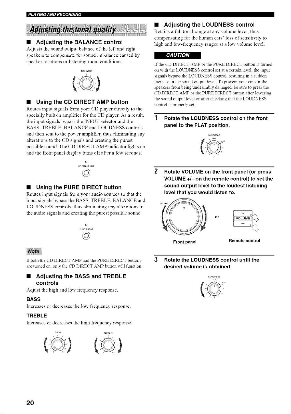
• Adjusting the LOUDNESS control
Retains a full tonal range at any volume level, thus
compensating for the human ears' loss of sensitivity to
high and low-fi'equency ranges at a low volume level.
If the CD DIRE( T AMP or the PURE DIRECT button is turned
on with the LOUDNESS control set at a certain level, the input
signals bypass the LOUDNESS control, resulting in a sudden
increase in the sotmd output level. To prevent yotLr ears or the
speakers from being undesirably damaged, be sure to press the
CD DIRECT AMP or the PURE DIRECT button after lowering
the sound output level or after checking that the LOUDNESS
control is properly set.
1 Rotate the LOUDNESS control on the front
panel to the FLAT position.
LOUDHESS
Rotate VOLUME on the front panel (or press
VOLUME +/- on the remote control) to set the
sound output level to the loudest listening
level that you would listen to.
Front panel
or
Remote control
3 Rotate the LOUDNESS control until the
desired volume is obtained.
LOUDNESS
FLAT
20
'2f__lYhv[ef__ y_Vel:l_o]:le]hv[J
• The VOLUME. BASS, TREBLE. BALANCE and
LOUDNESS controls and the CD DIRECT AMP and the PURE
DIRECT buttons have no effect on the source being recorded.
• Check the copyright laws in your countD; to record from
records. CDs. radio, etc. Recording copyright-protected
material may infringe on cop?right laws.
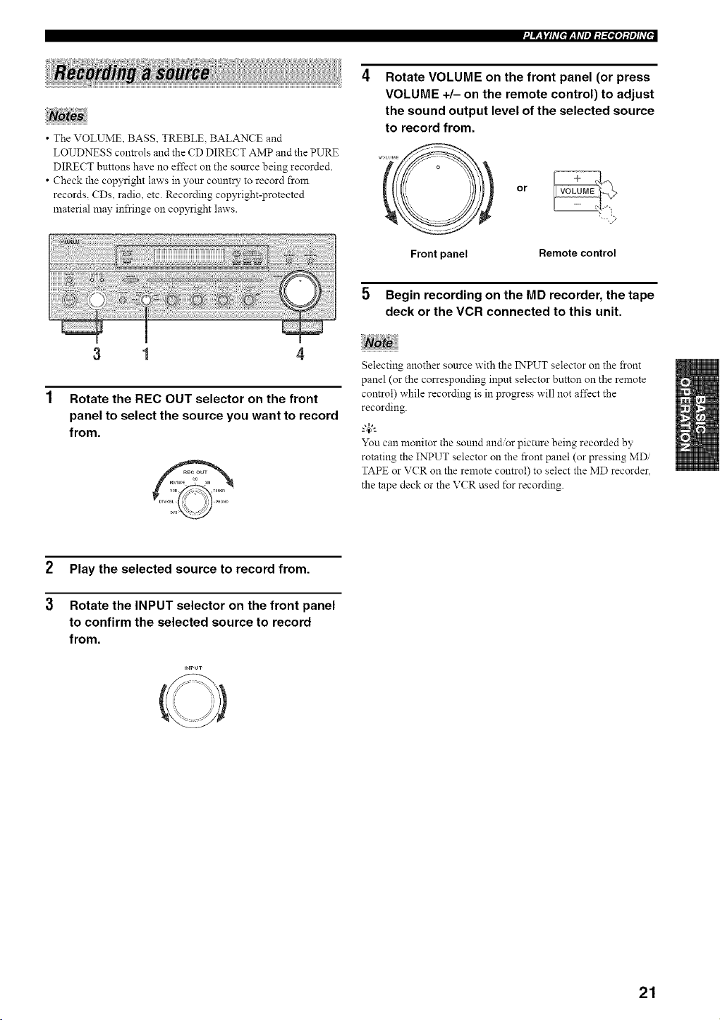
3 1
1 Rotate the REC OUT selector on the front
panel to select the source you want to record
from.
Rotate VOLUME on the front panel (or press
VOLUME +/- on the remote control) to adjust
the sound output level of the selected source
to record from.
or
Front panel Remote control
5 Begin recording on the MD recorder, the tape
deck or the VCR connected to this unit.
iii iiiii
Selecting another source with the INPUT selector on the _ont
panel (or the corresponding input selector button on the remote
control) while recording is in progress will not affect the
recording.
-"4_"-
You can monitor the sound and/or picture being recorded by
rotating the INPUT selector on the froN panel (or pressing MDi
TAPE or VCR on the remote control) to select the MD recorder.
the tape deck or the VCR used for recording.
2
3
Play the selected source to record from.
Rotate the INPUT selector on the front panel
to confirm the selected source to record
from.
=NPUT
21
iltJIF:lglld[eiF:Ydlel_l:[_e]_te]ld[J
Use this feature to automatically set this unit to the
standby mode after a certain amount of time. The sleep
timer is useful when you are going to sleep while this unit
is playing or recording a source. The sleep timer also
automatically turns off any external components
connected to the AC OUTLETS.
Press SLEEP repeatedly so that SLEEP OFF
appears in the front panel display.
SLEEP
....mL,= L,=L,= i m==,mi i
After a few seconds, SLEEP OFF disappears from the
front panel display, and the SLEEP indicator tums
off.
The sleep timer setting can also be canceled by pressing
STANDBY on the remote control (or MAIN ZONE O_OFF or
MASTER ON/OFF on the front panel) to set this unit to the
standby mode.
• The sleep timer can only be set with the remote control.
• The sleep timer automatically turns off Zone 2. However. the
power of Zone 2 components are not turned off.
1 Press one of the input selector buttons on
the remote control to select an input source.
2 Start playback on the selected input source.
3 Press SLEEP repeatedly to set the amount of
time before this unit is set to the standby
mode.
Each time you press SLEEP, the fi'ont panel display
changes as shown below.
SLEEP
_ ::::,i.,j::j::jJ?,:,::i:::{iq:t,i"__> :i;L.i_i_F'9_:_iiq:i,i"_,=.iiii ii ........
FFF' ,:!4::ii'_:!.i'_<- :i;L.Ei_;F'_!:4::ii'_:!.i'_
The SLEEP indicator flashes while switching the
amount of time for the sleep timer.
22
'Jf__l¥1d[ef__IdleJ:l=[esre]=te]ld[J
Press MUTE on the remote control to mute
the sound output.
The MUTE indicator flashes in the front panel
display and MUTE ON appears in the front panel
display.
M i i'°r°i2° i°°'ii°°.i
mmm==,==m m.... ,==,=_,
After a few seconds, MUTE ON disappears from the
l'ront panel display.
2 Press MUTE on the remote control again to
resume the sound output.
The MUTE indicator disappears from the front panel
display.
23
There are 2 tuning methods autonmtic and manual. Select either method according to your preference and the strength of
station signals.
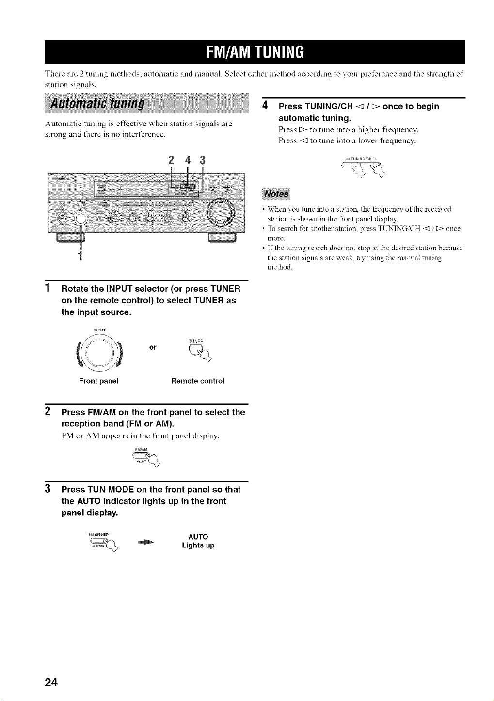
Automatic tuning is effective when station signals are
strong and there is no interference.
243
Rotate the INPUT selector (or press TUNER
on the remote control) to select TUNER as
the input source.
INPUT
_ TUNER
or
Front panel Remote control
Press TUNING/CH <:1/ _> once to begin
automatic tuning.
Press C> to tune into a higher frequency.
Press <:1to tune into a lower frequency.
• When you _ule into a station, the frequency of the received
station is shown in the front panel display.
• To search for another station, press TUNING CH <1 C> once
more.
• If the tuning search does not stop at the desired station because
the station signals are weak, try using the manual tuning
method.
Press FM/AM on the front panel to select the
reception band (FM or AM).
FM or AM appears in the front panel display.
FM/AM
Press TUN MODE on the front panel so that
the AUTO indicator lights up in the front
panel display.
_o,_,.p AUTO
Lights up
24
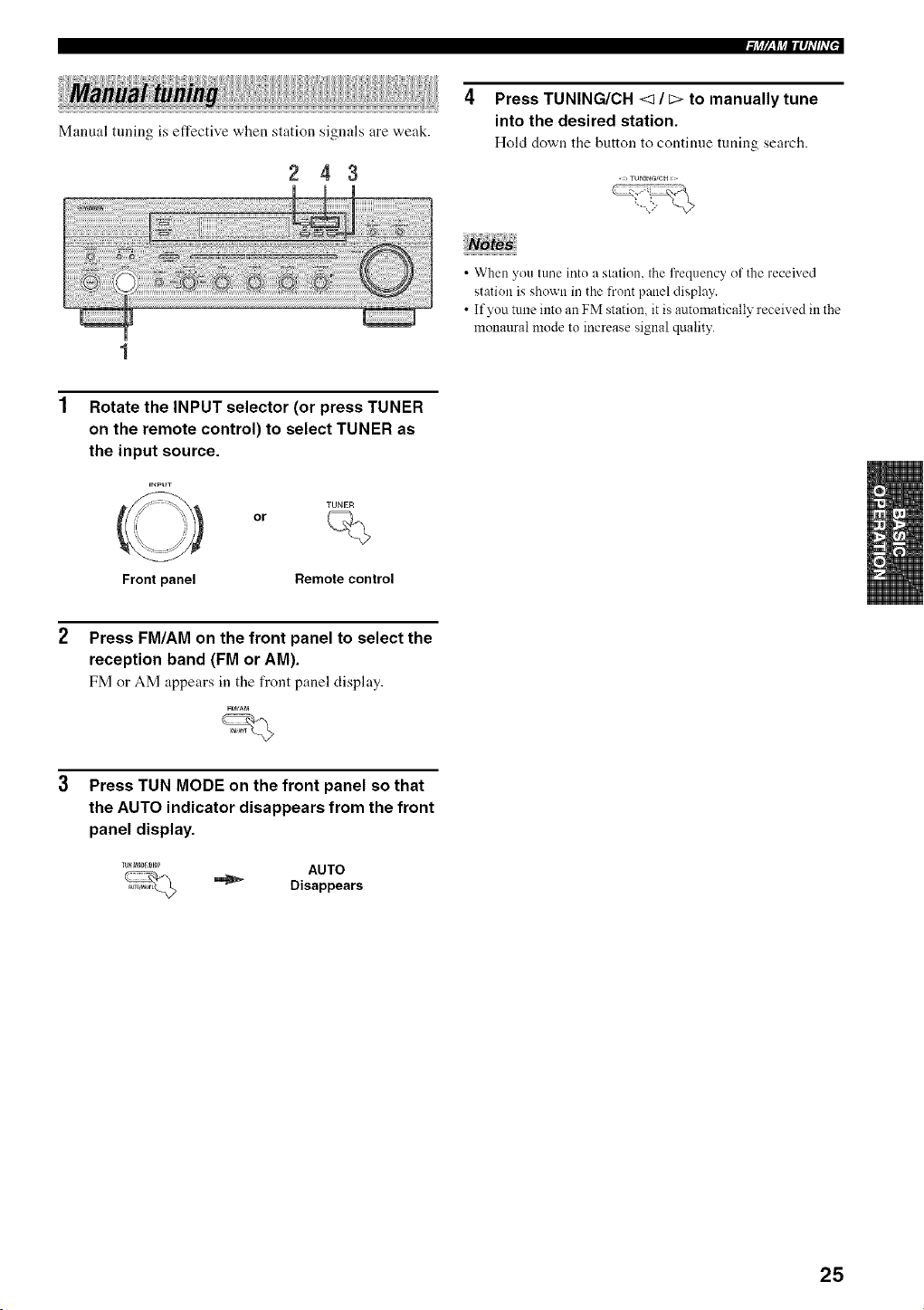
Manual tuning is effective when station signals are weak.
243
l+tr,_Y+tllqi'/fi'P
4 Press TUNING/CH <1 / c> to manually tune
into the desired station.
Hold down tile button to continue tuning search.
• When you tune into a station, the frequency ol the received
station is shown in the front panel display.
• If you tune intoan FM station, it is automatically received in the
monattral mode to increase signal quality.
Rotate the INPUT selector (or press TUNER
on the remote control) to select TUNER as
the input source.
+NPUT
(C _ TUNER
or
Front panel Remote control
Press FM/AM on the front panel to select the
reception band (FM or AM).
FM or AM appears in the front panel display.
FM/API
Press TUN MODE on the front panel so that
the AUTO indicator disappears from the front
panel display.
+mm+++,mp AUTO
_ Disappears
25
l;jV_j_|lql'lh7_
You can use the automatic preset tuning method to
automatically store FM stations. This fimction enables this
unit to automatically tune into FM stations with strong
signals and store up to 40 (8 stations in each of the 5
groups, AI to ES) of those received stations in order. You
can then easily recall any preset stations by selecting the
preset station numbers where they are stored.
• Any station data stored under a preset station number is cleared
when you store a new station under that preset station number.
• If the number of received stations does not reach 40 (E8),
automalic preset tuning automatically stops once searching all
available stations are tuned into and stored.
• Only FM stations with suflicient signal strength are stored
automatically by automatic preset tuning. If the station you
want to store is weak in signal strength, try using the manual
preset tuning method.
2 84
Press FM/AM on the front panel to select FM
as the reception band.
FM appears in the t>ont panel display.
F_AM
Press and hold MEMORY on the front panel
for more than 3 seconds.
The preset station group and the MEMORY and
AUTO indicators flash in the front panel display.
Press TUNING/CH <1/E> once to begin
automatic preset tuning.
Press C> to tune into higher frequencies.
Press <1 to tune into lower frequencies.
When automatic preset tuning is complete, the
frequency of the last preset station is shown in the
front panel display.
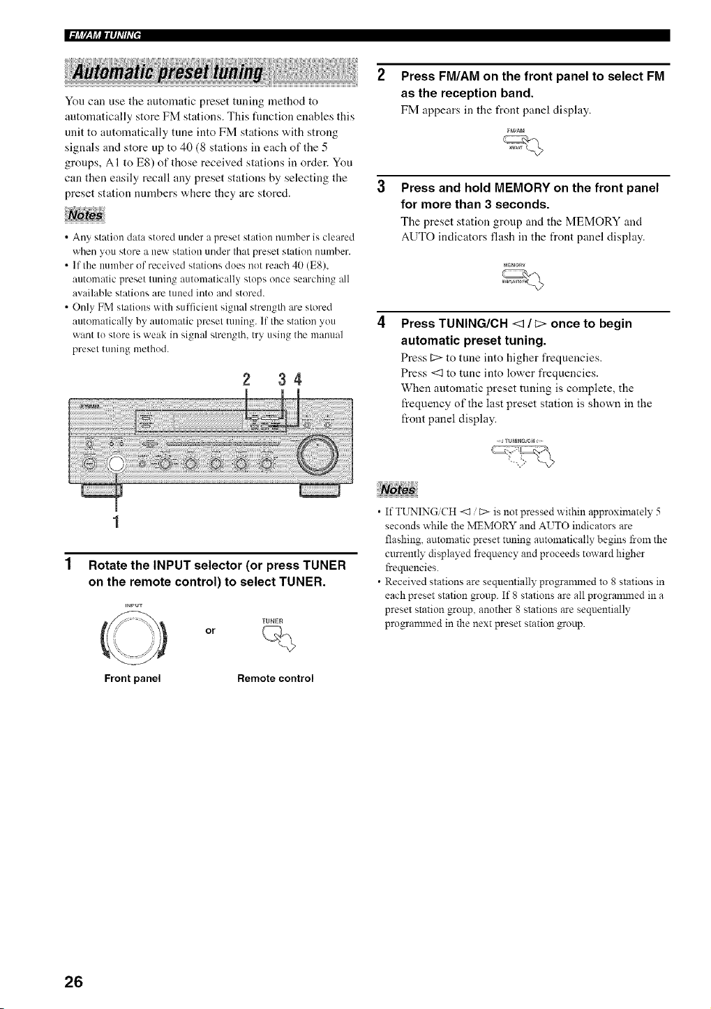
1
Rotate the INPUT selector (or press TUNER
on the remote control) to select TUNER.
=NPu-r
_) TUNEF_
or
Front panel Remote control
• If TL_P'.IINGiCH<1 / C> is not pressed within approximately 5
seconds while the MEMORY and AUTO indicators are
flashing, automatic preset ttming automatically begins from the
currently displayed frequency and proceeds toward higher
frequencies.
• Received stations are sequentially progrannned to 8 stations in
each preset station group. If 8 stations are all progrannned in a
preset station group, another 8 stations are sequentially
programmed in the next preset station group.
26
• Customized automatic preset tuning
You can specify a preset station group and it preset station
number from which this unit stores the FM stations
received by automatic preset tuning.
1 Press and hold MEMORY on the front panel
for more than 3 seconds.
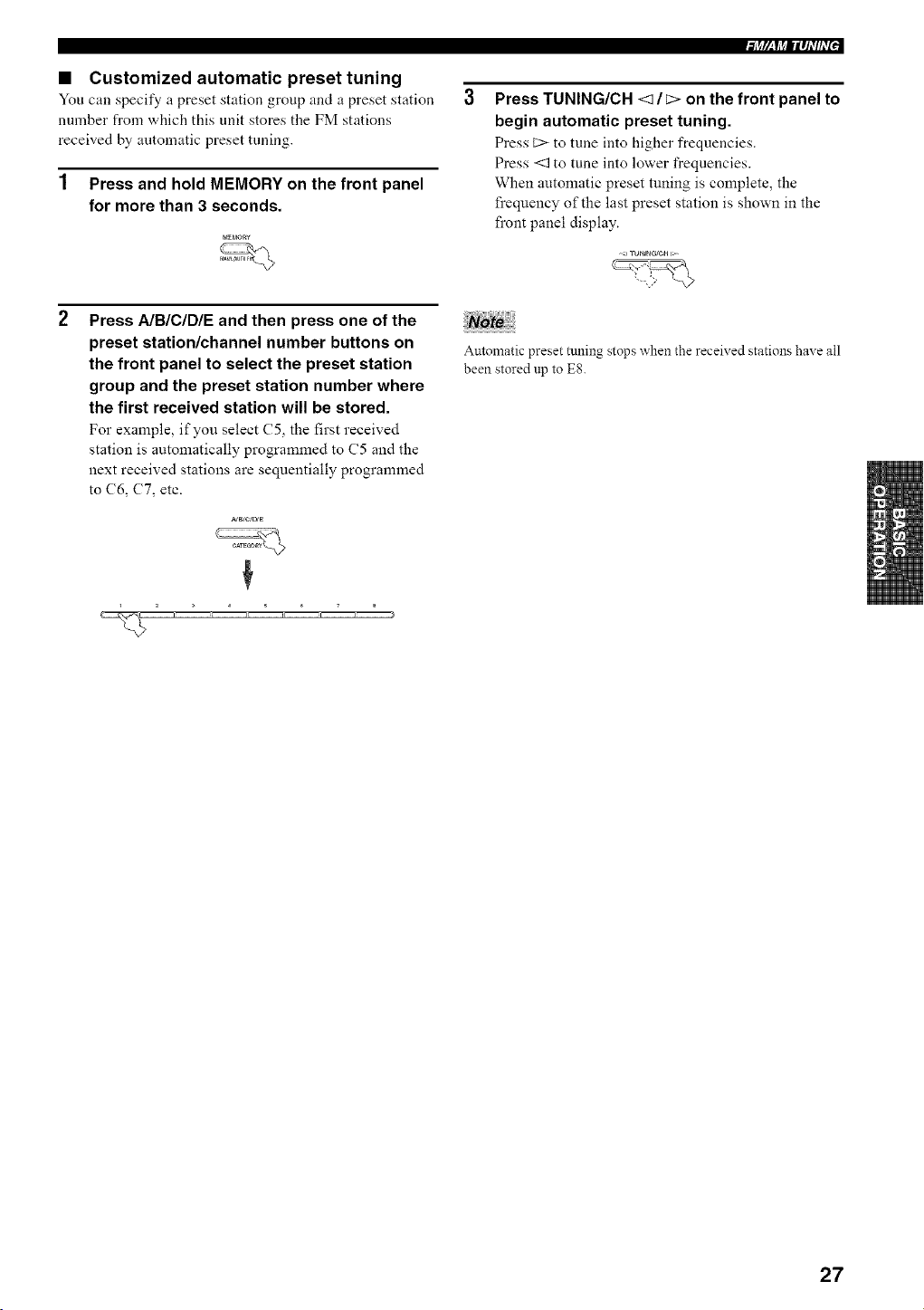
Press A/B/C/D/E and then press one of the
preset station/channel number buttons on
the front panel to select the preset station
group and the preset station number where
the first received station will be stored.
For example, if you select (75, the first received
station is automatically programmed to C5 and the
next received stations are sequentially programmed
to (76, (77, etc.
rigg_Yi'_|lql'lfl'[J
Press TUNING/CH <1 / E> on the front panel to
begin automatic preset tuning.
Press t::> to tune into higher frequencies.
Press <1 to tune into lower frequencies.
When automatic preset tuning is complete, the
frequency of the last preset station is shown in the
front panel display.
Automatic preset tuning stops when the received stations have all
been stored np to E8.
27
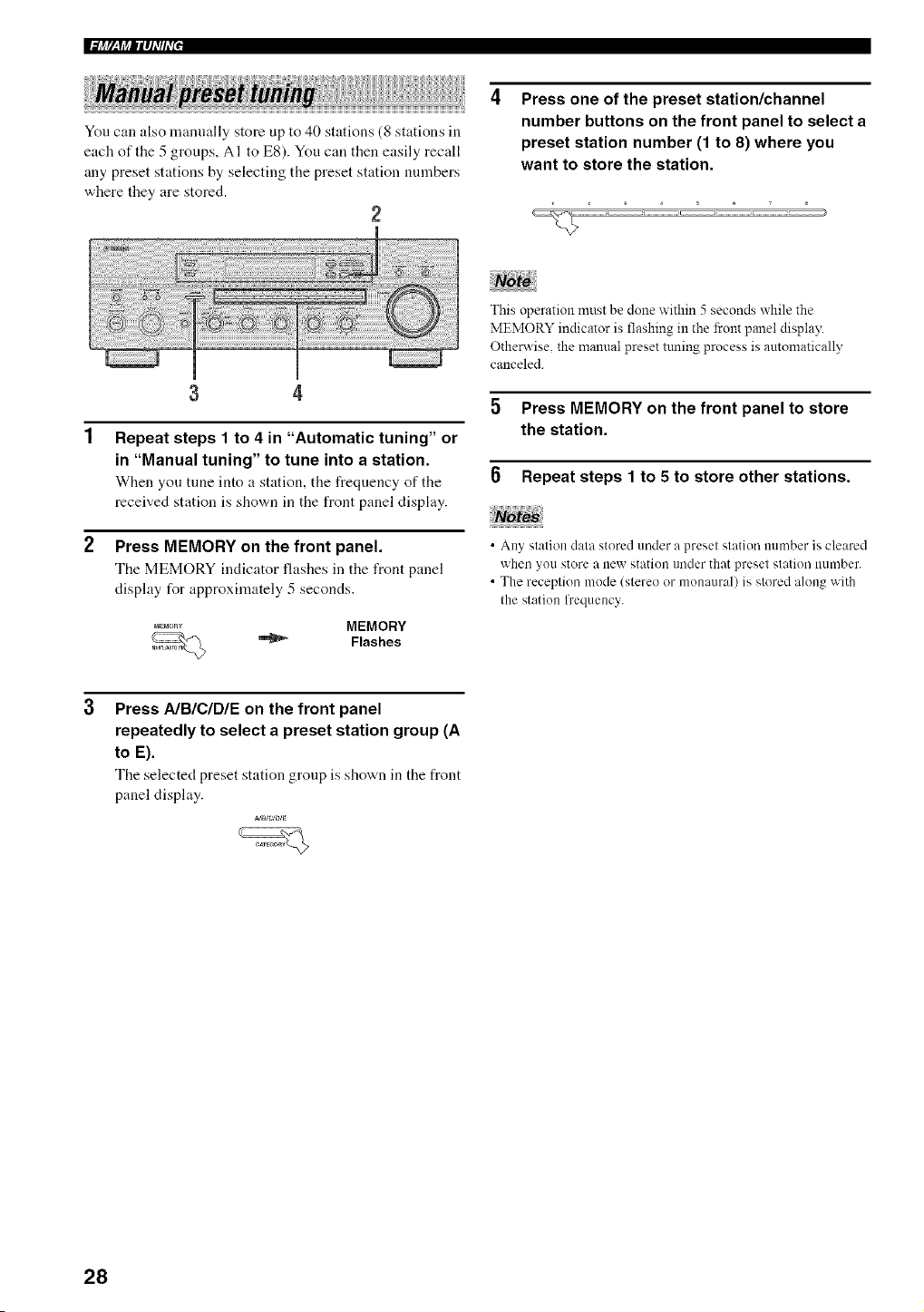
You can also manually store up to 40 stations (8 stations in
each of the 5 groups, AI to E8). You can then easily recall
any preset stations by selecting the preset station nmnbers
where they are stored.
2
Press one of the preset station/channel
number buttons on the front panel to select a
preset station number (1 to 8) where you
want to store the station.
3 4
Repeat steps 1 to 4 in "Automatic tuning" or
in "Manual tuning" to tune into a station.
When you tune into a station, tile frequency of tile
received station is shown in the front panel display.
Press MEMORY on the front panel.
The MEMORY indicator flashes in the front panel
display for approxinmtely 5 seconds.
,,_E_o._ MEMORY
_ Flashes
This operation must be done within 5 seconds while the
MEMORY indicator is flashing in the front panel display.
Otherwise, the manual preset ttming process is automatically
canceled.
5 Press MEMORY on the front panel to store
the station.
0 Repeat steps 1 to 5 to store other stations.
• Any station data stored under a preset station mnnber is cleared
when you store a new station under that preset station nun/ber.
• The reception mode (stereo or monaural) is stored along with
the station l]'equency.
Press AIBIC/DIE on the front panel
repeatedly to select a preset station group (A
to E).
The selected preset station group is shown in the front
panel display.
_a/ctD_e
28
+Ig,_f++llq_'If_'P
You can tune into the desired station simply by selecting
the preset station mnnber where it is stored.
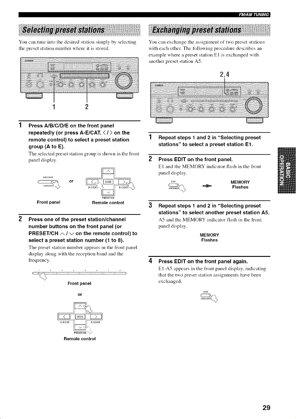
You can exchange the assignment of two preset stations
with each other. The following procedure describes an
example where a preset station El is exchanged with
another preset station A5.
2,4
1 2
Press A/B/C/DIE on the front panel
repeatedly (or press A-E/CAT. < / ) on the
remote control) to select a preset station
group (A to E).
Tile selected preset station group is sho'a,n in tile front
panel display.
or
PRESET/CH
Frontpanel Remotecontrol
Press one of the preset station/channel
number buttons on the front panel (or
PRESET/CH/,, / v on the remote control) to
select a preset station number (1 to 8).
Tile preset station number appears in tire front panel
display along with the reception band and the
frequency.
Front panel
or
1 Repeat steps 1 and 2 in "Selecting preset
stations" to select a preset station El.
2 Press EDIT on the front panel.
El and the MEMORY indicator fhtsh in tire front
panel display.
MEMORY
Flashes
Repeat steps 1 and 2 in "Selecting preset
stations" to select another preset station A5.
A5 and the MEMORY irMicator fhtsh in the front
panel display.
MEMORY
Flashes
Press EDIT on the front panel again.
El-A5 appears in the front panel display, indicating
that the two preset station assignments have been
exchanged.
P_IESET/CH'"",+."
Remote control
29
ii!iiiilWh_ii[i_ii;iHiii_i_iiii!i_ii/iiiii;iiii__iiiiiiiii__ii{{iiiii?<iiiiiii_/;qiiilJ!Jiiq!iiii;;;/iiiiiiiiii}_::iiiii_il_i;_i!i!!iii_ i;i:;iii_i_i_i_iiiii_ii{ii_ i/l_i!}_i i!i__iiii!i}iiiii!}ii!ii!!!iiiii!llii{llii!llii!llii!iXii_'iY{_iiiiiJii';iiiiiiiiiii/ii/ii_ iiiW_ii_ i_iii Iil_ilIl!_li
XM Satellite Radio is the satellite radio service with
millions of listeners across the United States broadcasting
live daily. The XM Satellite Radio channel lineup includes
more than 150 digital channels of choice from coast to
coast: 67 commercial-free music channels, featuring hip
hop to opera, classical to country, bluegrass to blues; 64
channels of premier sports, talk, comedy, children's and
entertaimnent pmgrannning; and more than 26 channels
of the traffic and weather information for major
metropolitan areas nationwide.
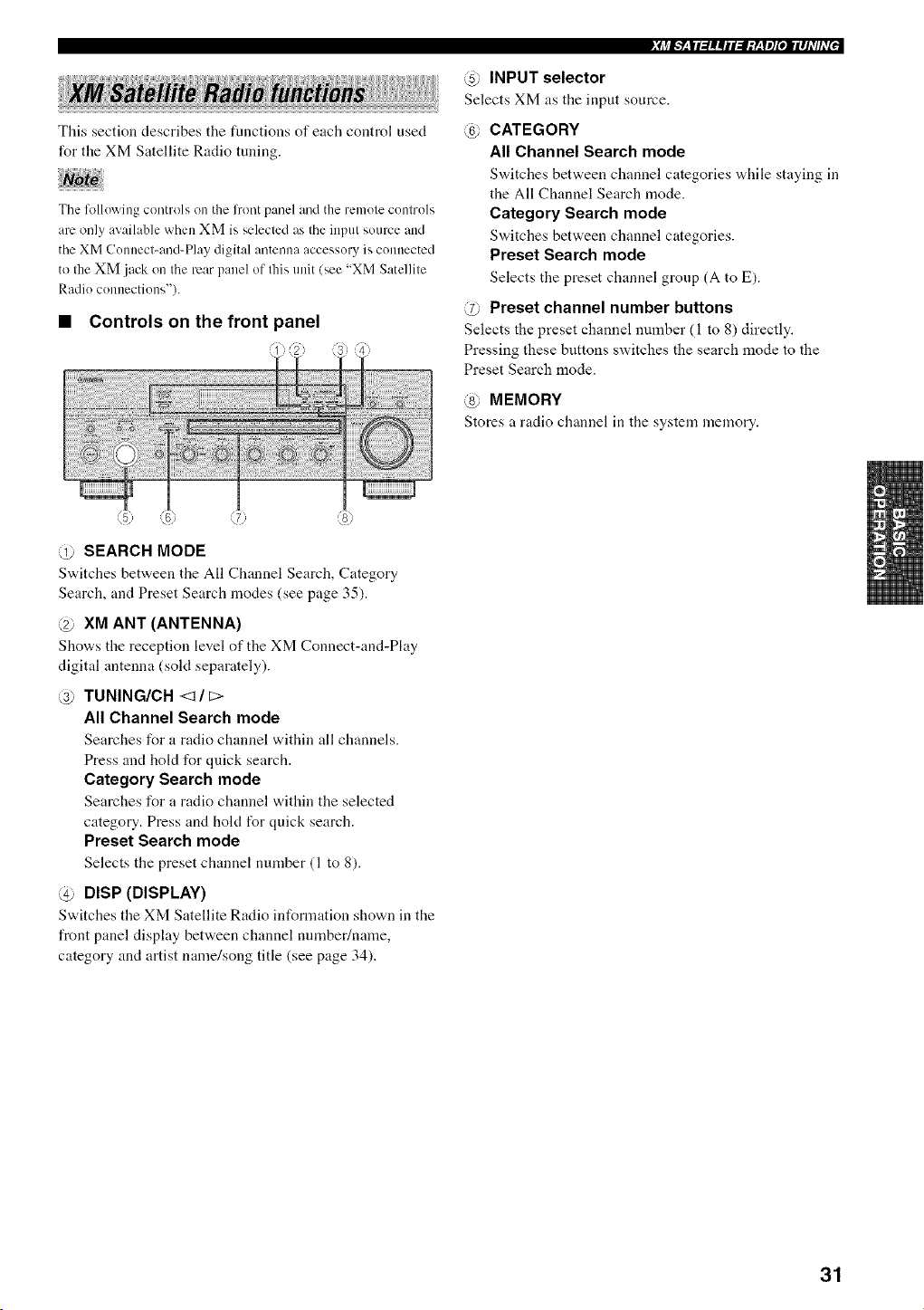
Connect the XM Connect-and-Play digital antenna
accessory (sokt separately) to the XM jack on the rear of
this unit. (For details, refer to the operating instructions
provided with the XM Connect-and-Play digital antenna
accessory).
XM jack
Because XM Satellite Radio is a subscription service, you
will need to set up an account and activate service with
XM using your XM Satellite Radio I[) number. To check
your ID number, follow "Activating XM Satellite Radio"
on page 33. For flmher information on XM Satellite Radio
services, visit the XM Satellite Radio website at
"http://www.xmradio.com".
• The XM Satellite Radio service is only available irathe 48
contiguous United States (not available in Alaska and Hawaii).
• XM Connect_and-Play digital antenna accessory and monthly
subscription are sold separalely. For delails, visit the XM
Satellite Radio website al "http://vcvcw.xmradio.com".
READY
• For infornmtion on obtaining the XM Connect-and-Play digital
antenna accessory, visit the XM Satellite Radio website at
"http://www.xmradio.com" or consult your local retailer that
sells XM Ready products.
• To ensure the optimal reception of the XM Satellite Radio
signals, the XM Connect-and_Play digital antenna accessory
must be placed at or near a southerly lhcing window with 11o
obstacles in the path to the sky. You can mount it indoors or
olltdoors.
Information from XM Satellite Radio, Inc.
Hardware and required basic monthly subscription sold
separately. Premimn Channel available at additional monthly
cost. Installation costs and other fees and taxes, including a one-
time activation fee may apply. Subscription fee is consumer
only. All fees and programming sut'_iect to change.
Subscriptions subject to Customer A_eement available at
xmxadio.cona. Only available in the 48 contiguous United
States.
© 2005 XM Satellite Radio Inc. All rights reserved. All other
trademarks are the property of their respective owners.
3O
This section describes the functions of each control used
for the XM Satellite Radio tuning.
The fl)llowing controls on the l?ont panel and the remote controls
are only available when XM is selected as the input source and
the XM Connect-and-Play digital antenna accessory is connected
to the am ack on the rear panel of this unit (see "XM Satellite
Radio connections").
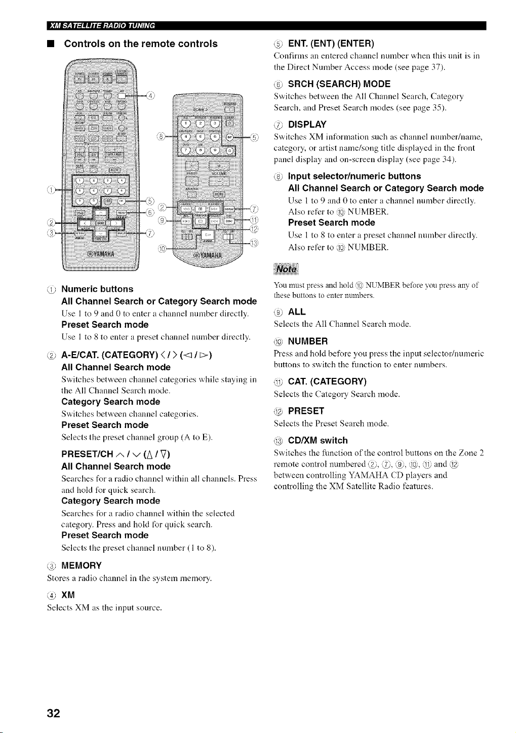
• Controls on the front panel
@ SEARCH MODE
Switches between tile All Channel Search, Category
Search, and Preset Search modes (see page 35).
XM ANT (ANTENNA)
Sho'a,s the reception level of the XM Connect-and-Play
digital antenna (sold separately).
3) TUNING/CH <_ / t:>
All Channel Search mode
Searches for a radio channel within all channels.
Press and hold for quick search.
Category Search mode
Searches for a radio channel w,ithin the selected
category. Press and hold for quick search.
Preset Search mode
Selects tile preset channel number (1 to 8).
@ DISP (DISPLAY)
Switches tile XM Satellite Radio information sho'a,n ill the
front panel display between channel number/name,
category and artist name/song title (see page 34).
Ji_J_Y__|l_llllil_l:y__yl][e, llllhT[hT[J
@ INPUT selector
Selects XM as the input source.
@ CATEGORY
All Channel Search mode
Switches between channel categories while staying ill
the All Channel Search mode.
Category Search mode
Sv,,itches between channel categories.
Preset Search mode
Selects the preset channel group (A to E).
@ Preset channel number buttons
Selects the preset channel number (1 to 8) directly.
Pressing these buttons switches the search mode to the
Preset Search mode.
@ MEMORY
Stores a radio channel ill the system memory.
31
|_i_l___|13||il:l:y__ylJ[OllllhTIhT[,
• Controls on the remote controls
@-
-{6) (_}-
(9)=
<7:
@ ENT. (ENT) (ENTER)
Confirms an entered channel number when this unit is iLL
the Direct Number Access mode (see page 37).
@ SRCH (SEARCH) MODE
Switches between the All Channel Search, Category
Search, and Preset Search modes (see page 35).
@ DISPLAY
Switches XM information such as channel number/name,
category, or artist name/song title displayed in the front
panel display and on-screen display (see page 34).
@ Input selector/numeric buttons
All Channel Search or Category Search mode
Use 1 to 9 and 0 to enter a channel number directly.
Also refer to @ NUMBER.
Preset Search mode
Use 1 to 8 to enter a preset channel number directly.
Also refer to @ NUMBER.
@ Numeric buttons
All Channel Search or Category Search mode
Use l to 9 and 0 to enter a channel number directly.
Preset Search mode
Use l to 8 to enter a preset channel number directly.
@ A-E/CAT. (CATEGORY) < / > (<3 / _>)
All Channel Search mode
Switches between channel categories while staying iLL
the All Channel Search mode.
Category Search mode
Switches bet'a, een channel categories.
Preset Search mode
Selects the preset channel group (A to E).
PRESET/CH/', / v (A / V)
All Channel Search mode
Searches for a radio channel within all channels. Press
and hold for quick search.
Category Search mode
Searches for it radio channel within tile selected
category. Press and hokt for quick search.
Preset Search mode
Selects the preset channel number (1 to 8).
@ MEMORY
Stores a radio channel in tile system memory.
@ XM
Selects XM its the input source.
You must press and hold @ NUMBER before you press aW of
these buttons to enter numbers.
@ ALL
Selects the All Channel Search mode.
@ NUMBER
Press and hold before you press the input selector/numeric
buttons to switch the function to enter numbers.
@ CAT. (CATEGORY)
Selects the Category Search mode.
@ PRESET
Selects the Preset Search mode.
@ CD/XM switch
Switches the function of the control buttons on the Zone 2
remote control numbered @, @, @, @, @ and @
between controlling YAMAHA CD players and
controlling the XM Satellite Radio l'eatures.
32
To sign up for an account with the XM Satellite Radio
service, an XM Satellite Radio ID number is required.
Follow the procedure below to check your ID number, and
then visit the website at "http://activate.xnlradio.com" or
call "1-800-XM-RADIO (1-800-967-2346)" to sign up
with your m_Lior credit card handy.
2 3
Press SEARCH MODE on the front panel (or
SRCH MODE on the remote control)
repeatedly to select the All Channel Search
mode.
ALL CH SEARCH appears in the front panel display.
or
Front panel Remote control
3 Press TUNING/CH <1 / c> on the front panel
(or PRESET/CH A / v on the remote control)
to select channel O.
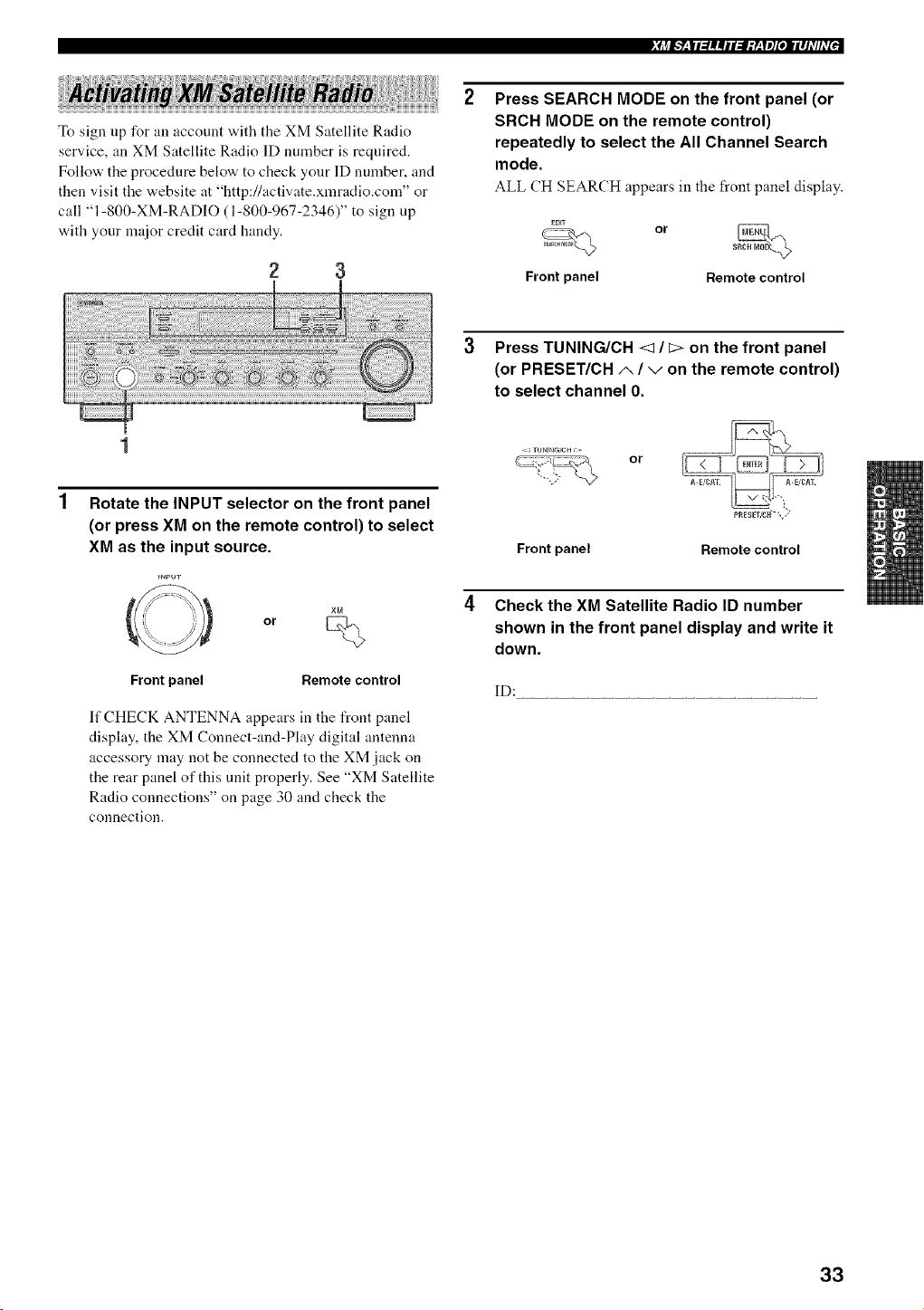
Rotate the INPUT selector on the front panel
(or press XM on the remote control) to select
XM as the input source.
Front panel Remote control
If CHECK ANTENNA appears in the front panel
display, the XM Connect-and-Play digital antenna
accessory may not be connected to the XM jack on
the rear panel of this unit properly. See "XM Satellite
Radio connections" on page 30 and check the
connection.
Front panel
or
Check the XM Satellite Radio ID number
shown in the front panel display and write it
down.
ID:
33
|_j_I___|I3||iI:I;y__yl][OIIII]_T/hT[,
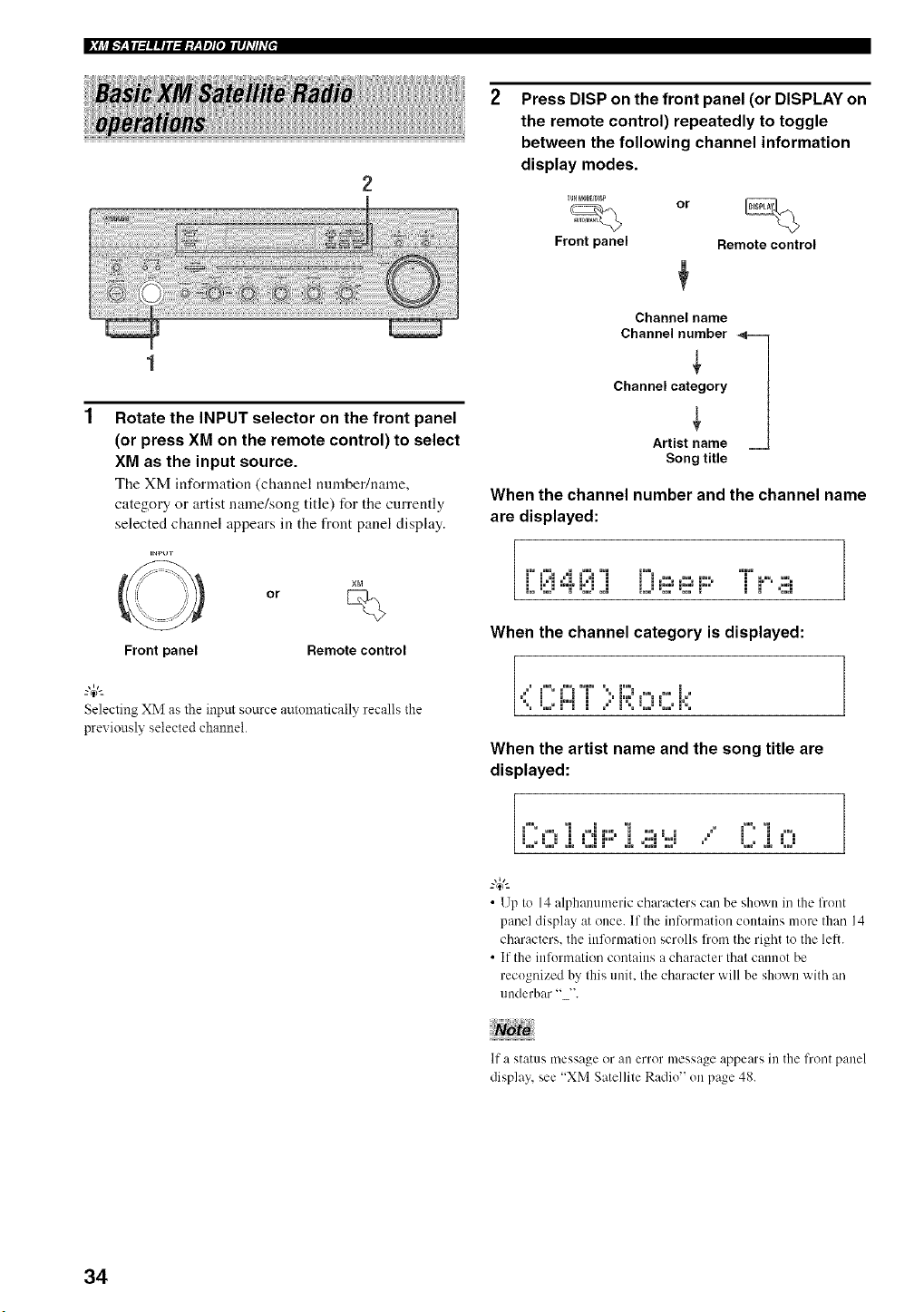
Rotate the INPUT selector on the front panel
(or press XM on the remote control) to select
XM as the input source.
The XM information (channel number/nanle,
category or artist name/song title) for the currently
selected channel appears in the front panel display.
=NPIJT
O
Front panel
or
Remote control
Selecting XM as the input source autolnatically recalls the
previously selected channel.
Press DISP on the front panel (or DISPLAY on
the remote control) repeatedly to toggle
between the following channel information
display modes.
Front panel Remote control
Channelname
Channelnumber_
Channel category
Artistname
Song title
When the channel number and the channel name
are displayed:
7
1'°¢°:; ,°1¢°:;'°1 ('°°m.......... °'1°'°..... /
L (::.1;'°)'(::.1.J LJ (:::m(:::m).oo' :; :;'' ....:°°';
/
When the channel category is displayed:
<i(2A[ )F;)0c i<
When the artist name and the song title are
displayed:
1
• 1Jp to 14 alphanumeric characters can be shown in the lhont
panel display at once. If the information contains more than 14
characters, the information scrolls from the right to the lett.
• If the inlormation contains a character that cannot be
recognized by this unit. the character will be shown with an
underbar "".
If a status message or all error message appears ill the front panel
display,see "XM Satellile Radio" on page 48.
34
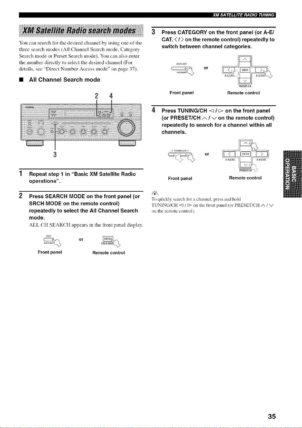
You can search for the desired channel by using one of the
three search modes (All Channel Search mode, Category
Search mode or Preset Search mode). You can also enter
the number directly to select the desired channel (For
details, see "Direct Number Access mode" on page 37).
• All Channel Search mode
2 4
Press CATEGORY on the front panel (or A-E1
CAT. < / > on the remote control) repeatedly to
switch between channel categories.
or
PRE;ET/CH
Front panel Remote control
Press TUNING/CH <1 / _> on the front panel
(or PRESET/CH A / v on the remote control)
repeatedly to search for a channel within all
channels.
1 Repeat step 1 in "Basic XM Satellite Radio
operations".
2 Press SEARCH MODE on the front panel (or
SRCH MODE on the remote control)
repeatedly to select the All Channel Search
mode.
ALL CH SEARCH appears in the front panel display.
Front panel
or _
Remote control
<J _U_E_G_CHc
or
Front panel Remote control
To quickly search lk_ra channel, press and hold
TUNING/CH <:3/ C>on the h'ont panel (or PRESET/CH A / v
on the remote control).
35
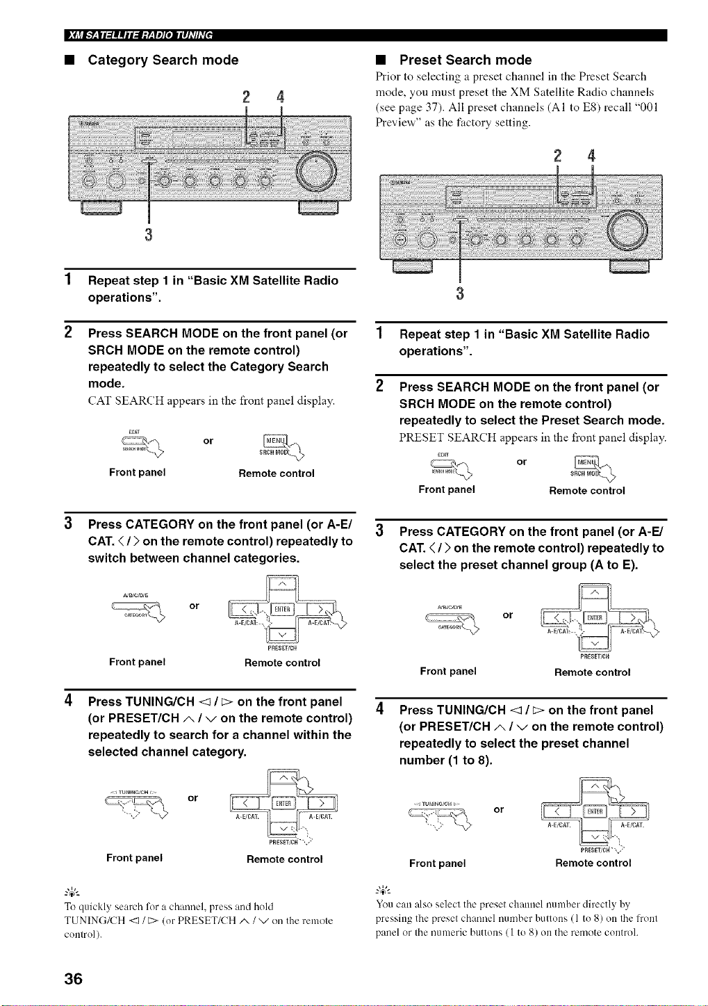
• Category Search mode
2
• Preset Search mode
Prior to selecting a preset channel in tile Preset Search
mode, you must preset the XM Satellite Radio channels
(see page 37). All preset channels (AI to ES) recall "001
Preview" as the factory setting.
2 4
1 Repeat step 1 in "Basic XM Satellite Radio
operations".
2 Press SEARCH MODE on the front panel (or
SRCH MODE on the remote control)
repeatedly to select the Category Search
mode.
CAT SEARCH appears in the front panel display.
Front panel
or
Remote control
3 Press CATEGORY on the front panel (or A-E/
CAT. < / > on the remote control) repeatedly to
switch between channel categories.
or
PREgET/CH
Front panel Remote control
Press TUNING/CH <t / t:> on the front panel
(or PRESET/CH _, / v on the remote control)
repeatedly to search for a channel within the
selected channel category.
- JTUNmGICH or
3
1 Repeat step 1 in "Basic XM Satellite Radio
operations".
2 Press SEARCH MODE on the front panel (or
SRCH MODE on the remote control)
repeatedly to select the Preset Search mode.
PRESET SEARCH appears in the front panel display.
EOEr
or
Front panel Remote control
3 Press CATEGORY on the front panel (or A-E/
CAT. < / > on the remote control) repeatedly to
select the preset channel group (A to E).
_JB/C_E
Front panel
or
PRESET/CH
Remote control
Press TUNING/CH <1 / _> on the front panel
(or PRESET/CH/,, / v on the remote control)
repeatedly to select the preset channel
number (1 to 8).
TU_ENG/CHC or
pRESET/¢H_'-,S
PRESET/Cff",_,"
Front panel Remote control Front panel Remote control
To quickly search %r a channel, press and hold
TUNING/CH <1 / C>(or PRESET/CH/x / v on the remote
control).
You can also select the preset channel number directly by
pressing the preset channel number buttons (1 to 8) on the lront
panel or the numeric buttons (I to 8) on the remote controh
36
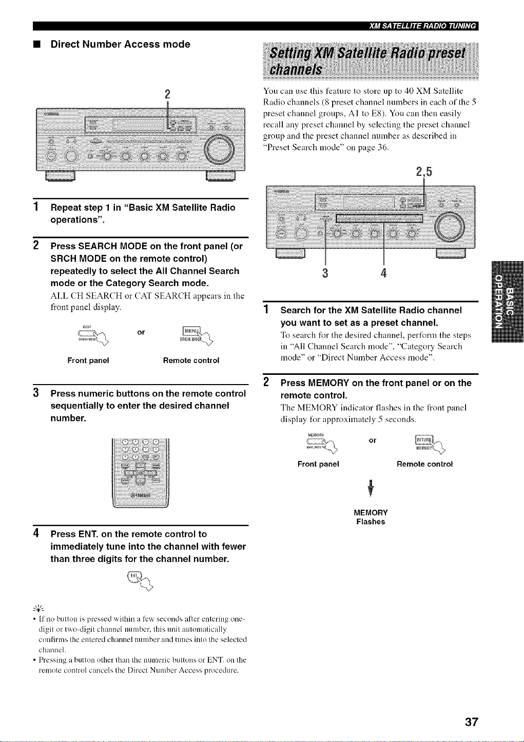
• Direct Number Access mode
_Ij_I.___|I:/I|iI:I;y__yl][oIIIIhT/hT[J
You can use this feature to store up to 40 XM Satellite
Radio channels (8 preset channel numbers in each of the 5
preset channel groups, AI to E8). You can then easily
recall any preset channel by selecting the preset channel
group and the preset channel number as described in
"Preset Search mode" on page 36.
2,5
1 Repeat step 1 in "Basic XM Satellite Radio
operations".
2 Press SEARCH MODE on the front panel (or
SRCH MODE on the remote control)
repeatedly to select the All Channel Search
mode or the Category Search mode.
ALL CH SEARCH or CAT SEARCH appears in the
front panel display.
or
Front panel Remote control
Press numeric buttons on the remote control
sequentially to enter the desired channel
number.
Press ENT. on the remote control to
immediately tune into the channel with fewer
than three digits for the channel number.
3 4
Search for the XM Satellite Radio channel
you want to set as a preset channel.
To search for the desired channel, pert_rm tile steps
in "All Channel Search mode", "Category Search
mode" or "Direct Number Access mode".
Press MEMORY on the front panel or on the
remote control.
The MEMORY indicator flashes in the front panel
display for approximately 5 seconds.
or
Front panel Remote control
MEMORY
Flashes
• If no button is pressed within a ti:w seconds after entering one-
digit or two-digit chmmel number, this unit automatically
confirnls the entered channel number and tunes into the selected
channel.
• Pressing a button other than the numeric buttons or ENT. on the
remote control cancels the Direct Number Access procedure.
37
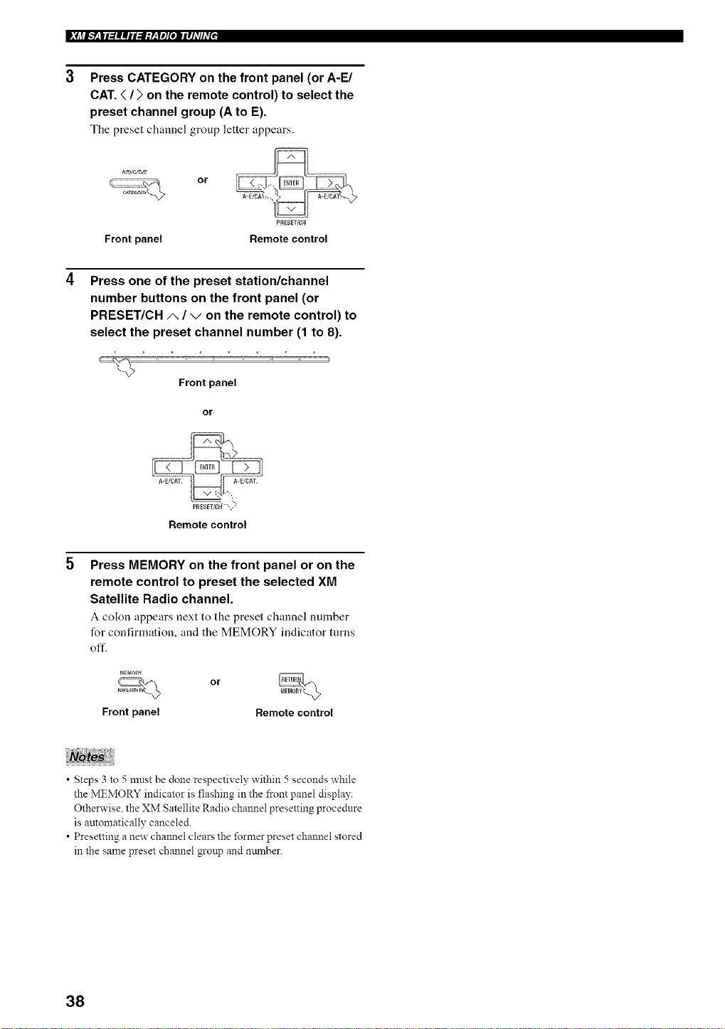
|_j_I___II3||iI:I;y__yl][OIIII]_T/hT[,
Press CATEGORY on the front panel (or A-E/
CAT. < / > on the remote control) to select the
preset channel group (A to E).
The preset channel group letter appears.
A_B_C/D/E
or
PRESET/CH
Front panel Remote control
Press one of the preset station/channel
number buttons on the front panel (or
PRESET/CH A / v on the remote control) to
select the preset channel number (1 to 8).
Front panel
or
Remote control
Press MEMORY on the front panel or on the
remote control to preset the selected XM
Satellite Radio channel.
A colon appears next to the preset channel number
for confirmation, and the MEMORY indicator turns
oft'.
MEMORY
Front panel
or
Remote control
• Steps 3 to 5 mnst be done respectively within 5 seconds while
the MEMORY indicator is flashing in the _ont panel display.
Otherwise, the XM Satellite Radio channel presetting procednre
is automatically canceled.
• Presetting a new chmmel clears the former preset channel stored
in the same preset channel gonp and mnnber.
38
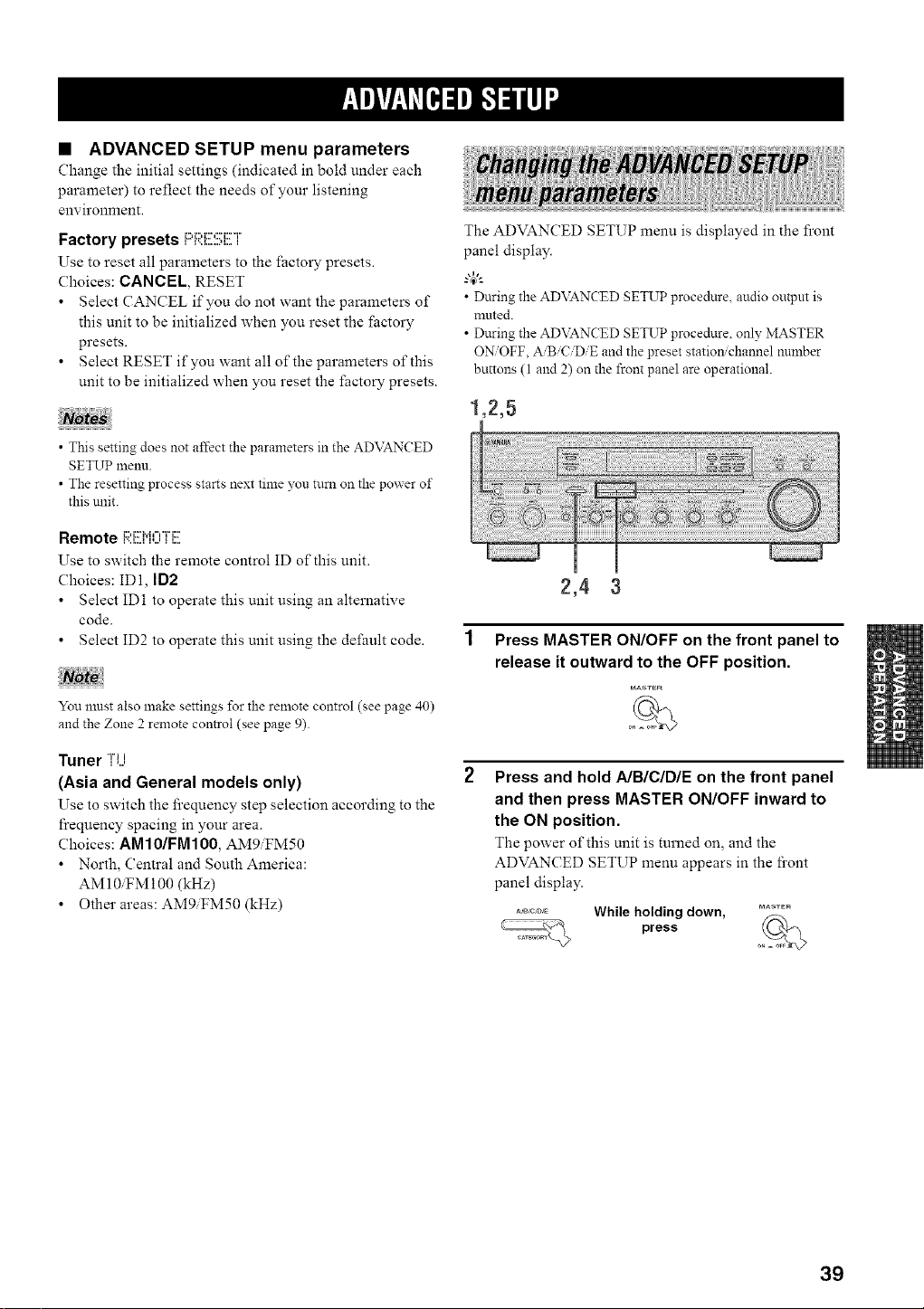
• ADVANCED SETUP menu parameters
Change the initial settings (indicated in bold under each
parameter) to reflect the needs of your listening
environment.
Factory presets i=q:;I:i!!!2!!;E]"
Use to reset all parameters to the factory presets.
Choices: CANCEL, RESET
Select CANCEL if you do not want the parameters of
this unit to be initialized when you reset the factory
presets.
Select RESET if you want all of the parameters of this
unit to be initialized when you reset the factory presets.
• This setting does not affect the parameters in the ADVANCED
SETUP menu.
• The resetting process starts next time yon turn on the power of
this unit.
Remote i:;I:i!!!M0[i!!!
Use to switch the remote control ID of this unit.
Choices: ID1, ID2
Select ID1 to operate this unit using an alternative
code
Select ID2 to operate this unit using the default code.
You must also make settings for the remote control (see page 40)
and the Zone 2 remote control (see page 9).
Tuner ]i...i
(Asia and General models only)
Use to switch the frequency step selection according to the
frequency spacing in your area.
Choices: AM10/FMIO0, AM9iFM50
• North, Central and South America:
AM 10iFM 100 (kHz)
Other areas: AMgiFM50 (kHz)
The ADVANCED SETUP menu is displayed in the front
panel display.
• During the AD\__N( ED SETUP procednre, audio outpnt is
mnted.
• During the AD\__N( ED SETUP procednre, only MASTER
O_OFF, A/B/C/DiE and the preset statio_ channel nnmber
buttons (1 and 2) on the front panel are operational.
1,2,5
2,4 3
Press MASTER ON/OFF on the front panel to
release it outward to the OFF position.
MAsr_R
Press and hold A/B/C/DIE on the front panel
and then press MASTER ON/OFF inward to
the ON position.
The power of this unit is turned on, and the
ADVANCED SETUP menu appears in the fi'ont
panel display.
_°_°_ While holding down, __
press o,_
39
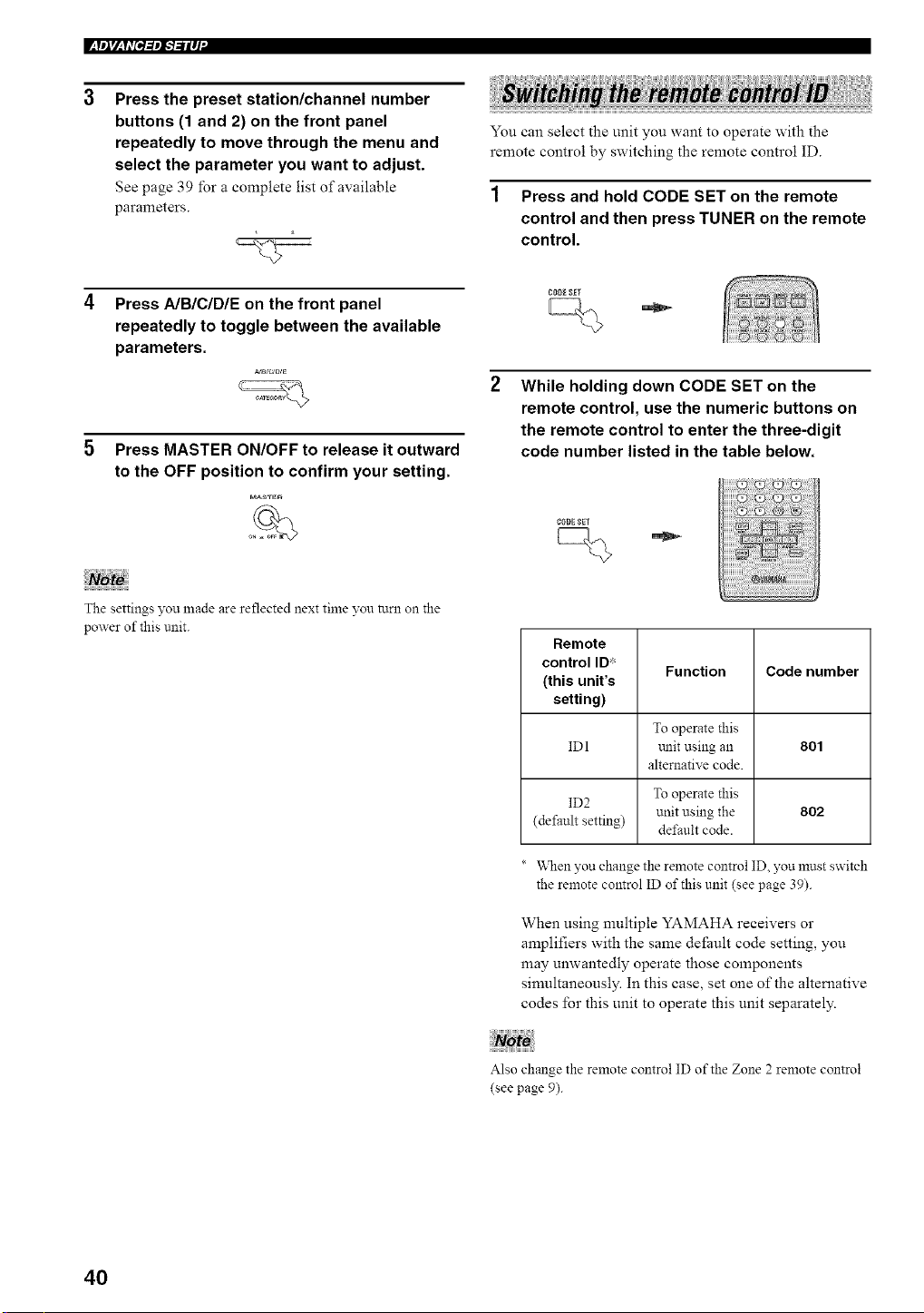
l_t',l_ h'N=,',I"I"iIq"
Press the preset station/channel number
buttons (1 and 2) on the front panel
repeatedly to move through the menu and
select the parameter you want to adjust.
See page 3 9 for a complete list of available
parameters.
You can select the unit you want to operate with the
remote control by switching the remote control ID.
1 Press and hold CODE SET on the remote
control and then press TUNER on the remote
control.
Press AIB/C/DIE on the front panel
repeatedly to toggle between the available
parameters.
Press MASTER ON/OFF to release it outward
to the OFF position to confirm your setting.
MA'_TE_
The settings you made are reflected next time you turn on the
power of this unit.
CODESET
While holding down CODE SET on the
remote control, use the numeric buttons on
the remote control to enter the three-digit
code number listed in the table below.
CODESET
Remote
control ID:'
Function Code number
(this unit's
setting)
To operate this
ID l unit using an 801
alternative code.
ID2 To operate this
unit using the 802
(default setting) det;ault code.
* \_len you change the remote control ID, you must switch
the remote control ID of this unit (see page 39).
When using multiple YAMAHA receivers or
amplifiers with the same default code setting, you
may unwantedly operate those components
simultaneously. In this case, set one of the alternative
codes for this unit to operate this unit separately.
Also change the remote control ID of the Zone 2 remote control
(see page 9).
40
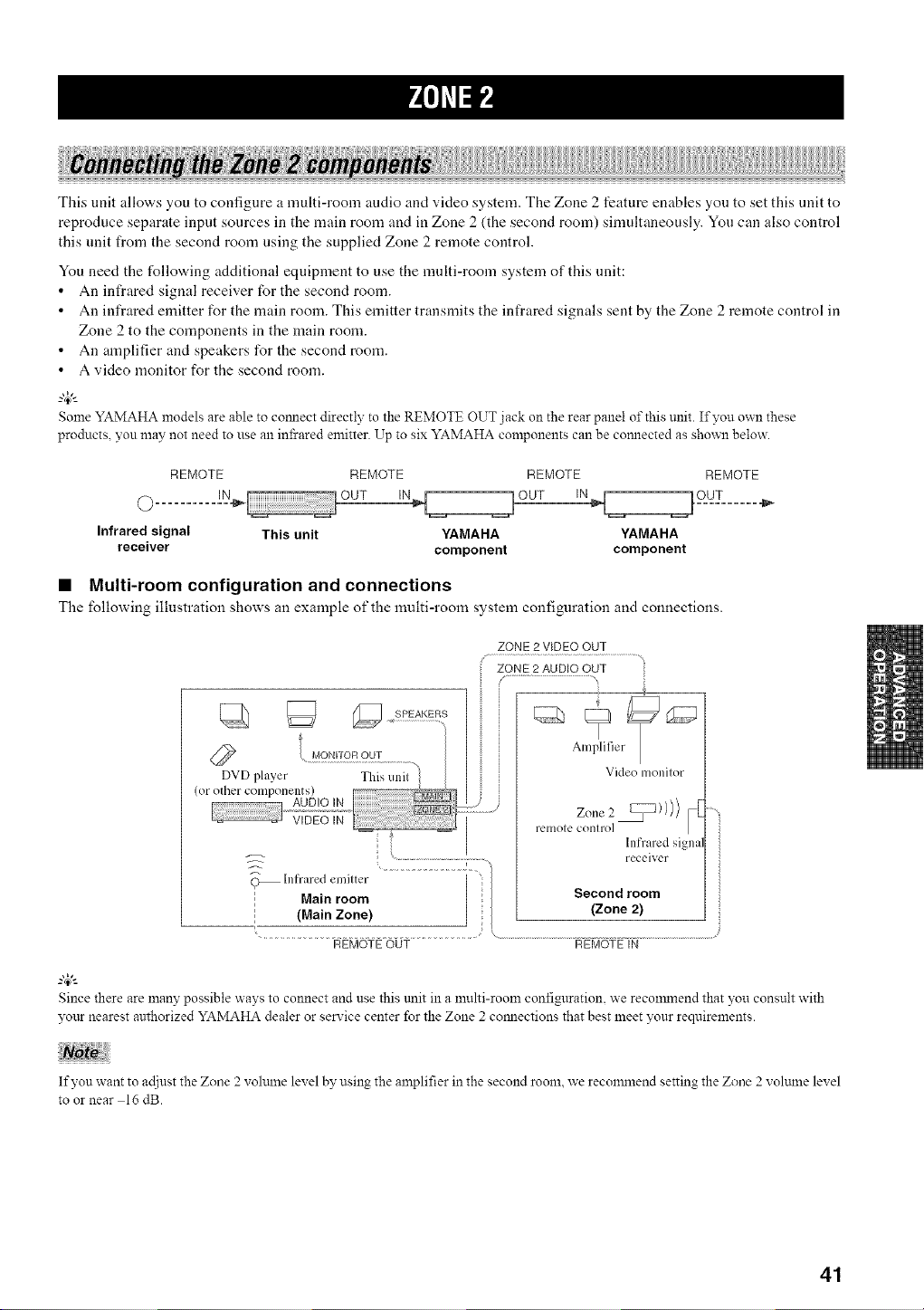
This unit allows you to configure a nmlfi-room audio and video system. The Zone 2 feature enables you to set this unit to
reproduce separate input sources in the main worn and in Zone 2 (the second room) simultaneously. You can also control
this unit from the second room using the supplied Zone 2 remote control.
You need the following additional equipment to use the nmlti-room system of this unit:
An infrared signal receiver for the second room.
An infrared emitter for the main room. This emitter transmits the infrared signals sent by the Zone 2 remote control in
Zone 2 to the components in the main room.
An amplifier and speakers for the second room.
A video monitor for the second room.
Some YAMAHA models are able to comlect directly to the REMOTE OUT jack on the rear panel of this unit. If you own these
T
products, you may not need to use an infrared emitter. Up to six YAMAHA components can be comlected as shown below.
REMOTE REMOTE REMOTE REMOTE
Infrared signal This unit YAMAHA YAMAHA
receiver component component
• Multi-room configuration and connections
The following illustration shows an example of the multi-room system coniim_ration and connections.
ZONE 2 V[DEO OUT
@
InfraredMainemilterroom ....................
(Main Zone)
Video monilor
relllOle conlro]
Infrared signa
receiver
Second room
(Zone 2)
REMOTEOUT REMOTEIN
Since there are many possible ways to connect and use this trait in a multi-room configuration, we reconnnend that you consult with
yottr nearest authorized YAMAHA dealer or service center for the Zone 2 comlections that best meet }'our requirements.
If yon want to adjust the Zone 2 volmne level by using the amplifier in the second room, we reconmlend setting the Zone 2 volmne level
to or near 16 dB.
41
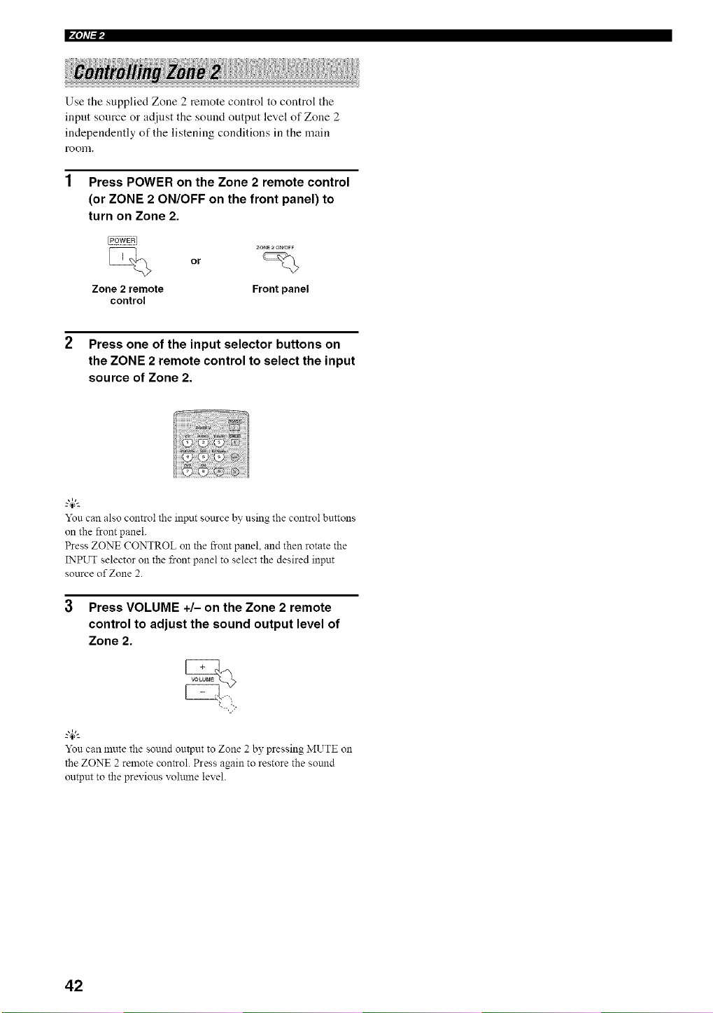
Use the supplied Zone 2 remote control to control the
input source or adjust the sound output level of Zone 2
independently of the listening conditions in the main
room.
1 Press POWER on the Zone 2 remote control
(or ZONE 2 ON/OFF on the front panel) to
turn on Zone 2.
Zone 2 remote
control
or
Front panel
2 Press one of the input selector buttons on
the ZONE 2 remote control to select the input
source of Zone 2.
You can also control the input source by using the control buttons
on the front panel.
Press ZONE CONTROL on the front panel, and then rotate the
INPUT selector on the front panel to select the desired input
source of Zone 2.
Press VOLUME +/- on the Zone 2 remote
control to adjust the sound output level of
Zone 2.
You can mute the sound output to Zone 2 by pressing MUTE on
the ZONE 2 remote control. Press again to restore the sound
output to the previous volmne level.
42
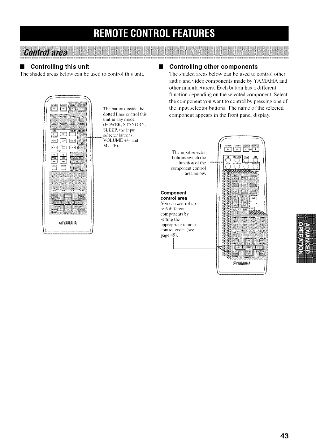
• Controlling this unit
The shaded areas below can be used to control this unit.
The buttons inside the
dotted lines control this
unit in any mode
(POWER, STANDBY,
SLEEP, the input
selector buttons,
VOLUME +_ and
MUTE).
• Controlling other components
The shaded areas below can be used to control other
audio and video components made by YAMAHA and
other manuf:tcturers. Each button has a different
flmction depending on the selected component. Select
the component you want to control by pressing one of
the input selector buttons. The name of the selected
component appears in the front panel display.
The input selector
buttons switch the
fimction of the
component control
area below.
Component
control area
Youcan controlup
to 6different
componentsby
setting the
appropriateremote
controlcodes(see
page45).
[
43
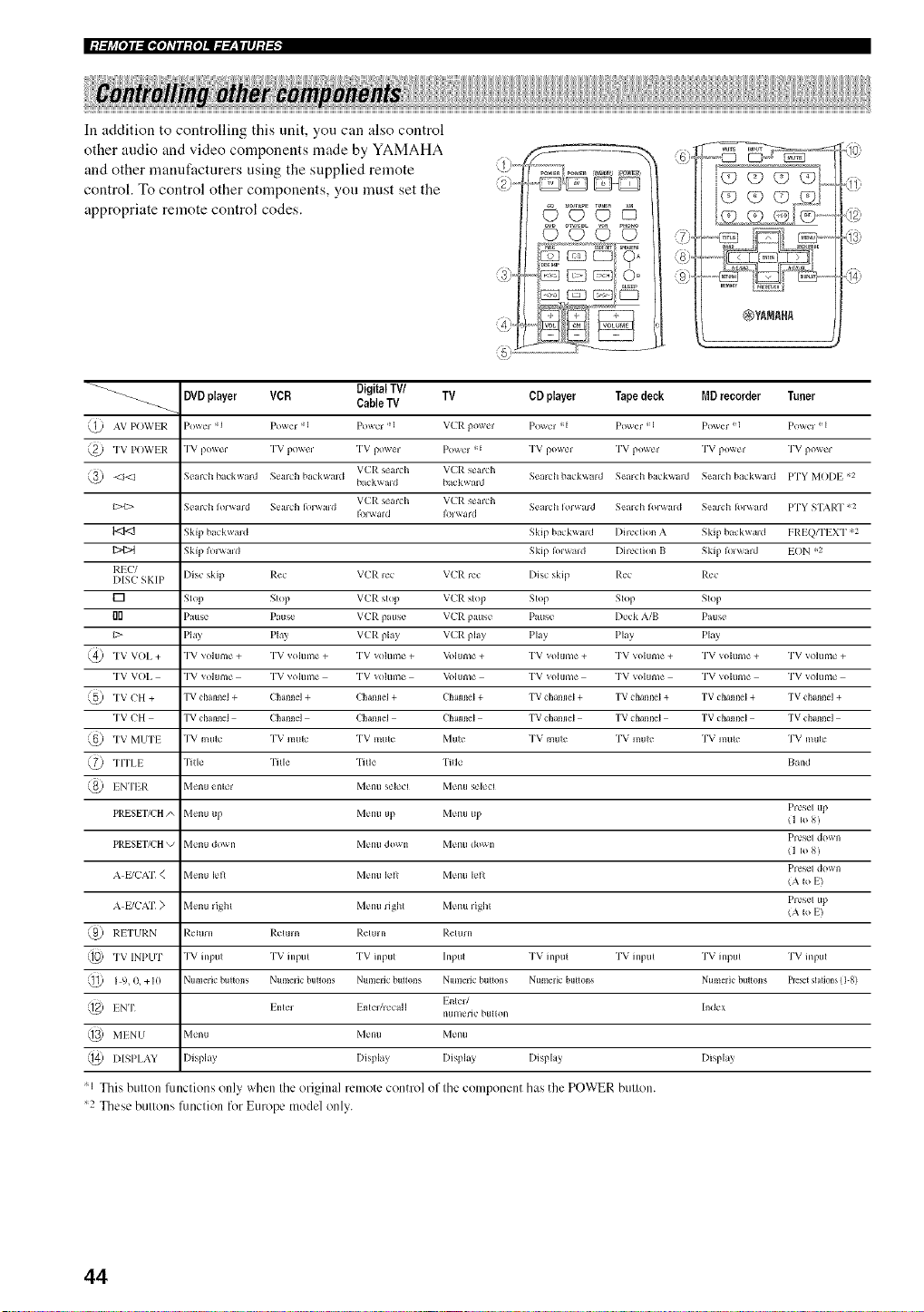
|:J.,_i_[o]ll[I,[o]_Til:{o]llffff__lllJ:l-'I"
In addition to controlling this unit, you can also control
other audio and video components made by YAMAHA
and other manufacturers using the supplied remote
control. To control other components, you must set the
appropriate remote control codes.
c) CJ C) m?
CD CJ CJ CJ
DVDplayer VCR Digital TV/ TV
_-_ CableTV
AV POWIR Powe_ "q Pm_er -I Powc_ ,_1 V(2R powe_
TV POWER TV powc_ TV powe_ TV pm_er Po_c_ "
VCR semh VCR search
_---/<1 Scarab ba(k_ard Sealh ba_kwald
ba k_ald ba k/_md
VL'P. searh VCR seaEh
c>t> Seard_ Ior_ard Semh R,iwmd Search Ior_ard SeaEb Ik,lwmd
I<:I<1 Skip ba_ kwaM Skip ba_kwmd I)ircclion A
{i_ Skip Ik)l_ald Skip I )_ald I)ircclion I/
RIJJ/
MSC SKIP I)is_ skip Re_ VCR le_ VCR rcc I)i_c skip Rc_
[] Slop Slop VCR slop VL'R stop Slop Stop
{]0 Pause Patlsc VCR pause VCR pause Pause I)_'_k A/B
C> Play Play VCR play VCR play Play Pkly
TV VOI. + "IW volume + TV volume + TV volume + M)lunle + 1W volunle + TV voIunle +
TV VOI. "IW vohlme TV vohlme TV vohlme M_hlnle 1W volunle TV vohmle
TV CH + TV channel + Channel + Channel + Channel + TV channel + TV channel +
TV CH TV channel Channel Channel Channel TV channel TV channel
TV MUTI "IW mule TV mule TV mute Mule TV mule TV mute
TrI'LI rl?lle "I] lie "I]lle lille
INTER Menu entei Menu selecl Menu seled
PRESET/CH A Menu up Menu up Menu up
PRESET/CH k/ MellU dOWll Melltl dowll Melltl dOWll
A E/CIV[" < Menu lell Menu lell Menu lell
A E/C,X[" ) Menu _ight Menu right Menu _ight
RI.TURN Reltlrn Relum Reluul Relurn
TV INPUT "IW inpul TV inpul TV hlput Inpul TV inpul TV inpul
I 9, 0, +I0 Numeric buttons Numeric bullons NumeiJc bll_lolls NumeiJc buttons Numeric butlons
Enter/
INT Inle_ I nteUlecaH
numeric btlHOll
MINU Menu Menu Menu
I)ISPI,AY I)isplay I)isplay Display I)isplay
'1 This button functions only when the original remote control of the component has the POWER button.
'2 These buttons flmction for Europe model only.
_J
>7.
CD player Tape deck MD recorder Tuner
Powel *1 Pm_er =:1 Pm_er ! 1 Powel ! l
TV powel TV power TV power "I'V po_ei
Scarb backboard Search ba_k_md Sea_h ha kwa_d PTY MOI)E ,2
Search I_)_wmd H'Y STAP.T _2
Skip backwald FRI Q/I"I XT ,,2
Skip I_ ward EON *2
Rec
Slop
Pause
Play
TV volume + TV volume +
TV volume TV volume
TV channel + TV channel +
TV channel TV channel
TV mule 1W mul_
Band
Presel up
(1 Io8)
Presel down
(1 Io8)
Presel down
(A I_>E)
Presel tip
(A Io E)
TV inpul 1W input
Numeric buttons P_set sta_ons (I-8)
hldex
I)isplay
44
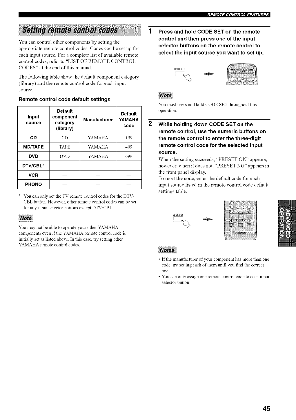
:/YIj_[O]IYJ[_,[O]_VlI:fO]II._.___flII]:/._
You can control other components by setting the
appropriate remote control codes. Codes can be set up for
each input source. For a complete list of available remote
control codes, refer to "LIST OF REMOTE CONTROL
(?ODES" at the end of this manual.
The following table show the default component category
(library) and the remote control code for each input
source.
Remote control code default settings
Default
Default
Input component Manufacturer YAMAHA
source category code
(library)
C D CD YAMAHA 199
M D/TAP E TAPE YAMAHA 499
DVD DVD YAMAHA 699
DTV/CBL*
VCR
PHONO
* You can only set the TV remote control codes _br the DTV ......
CBL button. However, other remote control codes can be set
for an), input selector buttons except DTV CBL.
Not
You may not be able to operate)'our other YAMAHA
components evan if the YAMAHA remote control code is
initially set as listed above. In this case. try setting other
YAMAHA remote control codes.
Press and hold CODE SET on the remote
control and then press one of the input
selector buttons on the remote control to
select the input source you want to set up.
CODESET
You must press and hold CODE SET throughout this
operation.
While holding down CODE SET on the
remote control, use the numeric buttons on
the remote control to enter the three-digit
remote control code for the selected input
source.
When the setting succeeds, "PRESET OK" appears;
however, when it does not, "PRESET NG" appears in
the front panel display.
To reset the code, enter the default code for each
input source listed in the remote control code default
settings table.
CODE_ET
• If the manufacturer of yoar component has more than one
code, try setting each of them tmtil you find the correct
one.
• You can only assign one remote control code to each input
selector button.
45
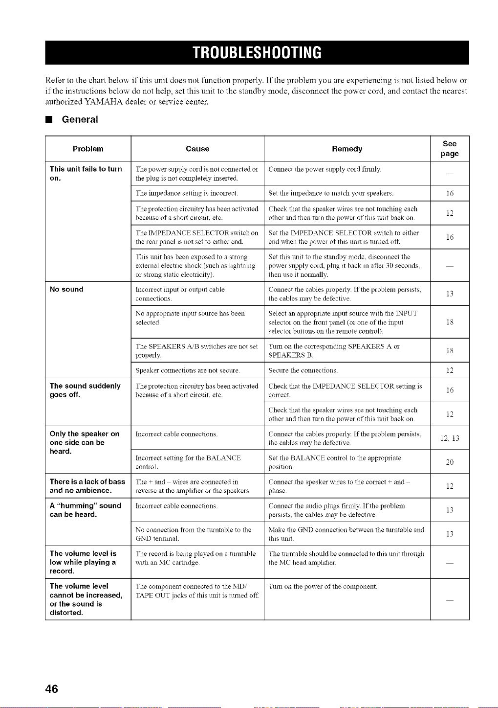
Refer to the chart below if this unit does not function properly. If the problem you are experiencing is not listed below or
if the instructions below do not help, set this unit to the standby mode, disconnect the power cord, and contact the nearest
authorized YAMAHA dealer or service center.
• General
See
Problem Cause Remedy
page
This unit fails to turn Tile power supply cozd is not connected 02 Connect tile powm supply cozd fimfl_
on. the plug is not completely inserted
The impedance setting is inconect. Set the impedance to match yore speakers. 16
The protection circuitzy ha s been activated Check that the speaker wires are not touching each 12
because of a shoz! circuit, etc. other and then ialrn the power of this unit back on
The IMPEDANCE SELECTOR switch on Set the IMPEDANCE SELECTOR switch to either
16
the rear panel is not set to either end end when the powa of this unit is turned otl_
This unit has been exposed to a strong Set this trait to the standby mode, disconnect the
external electric shock (such as lightning power supply cord, plug it back in after 30 seconds,
or strong static electaici_,), then use it nonnally.
No sound Inconect input or output cable Connect the cables properly If tile problem persists,
connections the cables may be defective
No aplJropriate input source has been Select an appropriate input somce with the INPUT
selected, selector on the fiont panel (or one of the input
selector buttons on the remote control)
The SPEAKERS _'B switches are not set Turn on the conesponding SPEAKERS A or
properly. SPEAKERS B.
Speaker connections are not secme. Secllre tile connections.
The sound suddenly
goes off.
The protection circuitz T ha s been activated
because ofa shozt circuit, etc.
Check that the IMPEDANCE SELECTOR setting is
conect.
Check that the speaker wires are not touching each
other and then ialrn the power of this unit back on
Only the speaker on Inconect cable connections Connect the cables properly. If the problem pmsists,
one side can be the cables may be defective
heard.
Inconect setting fo_ the BALANCE Set the BALANCE control to tile app!opriate
cotmol, position.
There is a lack of bass The + and wires are connected in Connect the speaker wires to the correct + and
and no ambience, reverse at the amplifier or tile speakms phase
A "humming" sound Inconect cable connections Connect tile audio plugs firmly. If the problem
can be heard, pmsists, the cables may be defective
No connection from the turntable to the Make the GND connection between the turntable and
GND terminal, this unit
The volume level is The record is being played on a turntable The turntable should be connected to this unit through
low while playing a with an MC camidge the MC head amplifier.
record.
The volume level Tile component connected to tile MDi Turn on tile powel of the conll3onent
cannot be increased, TAPE OUT jacks of this unit is ammd off.
or the sound is
distorted.
13
18
18
12
16
12
IL 13
2O
12
13
13
46
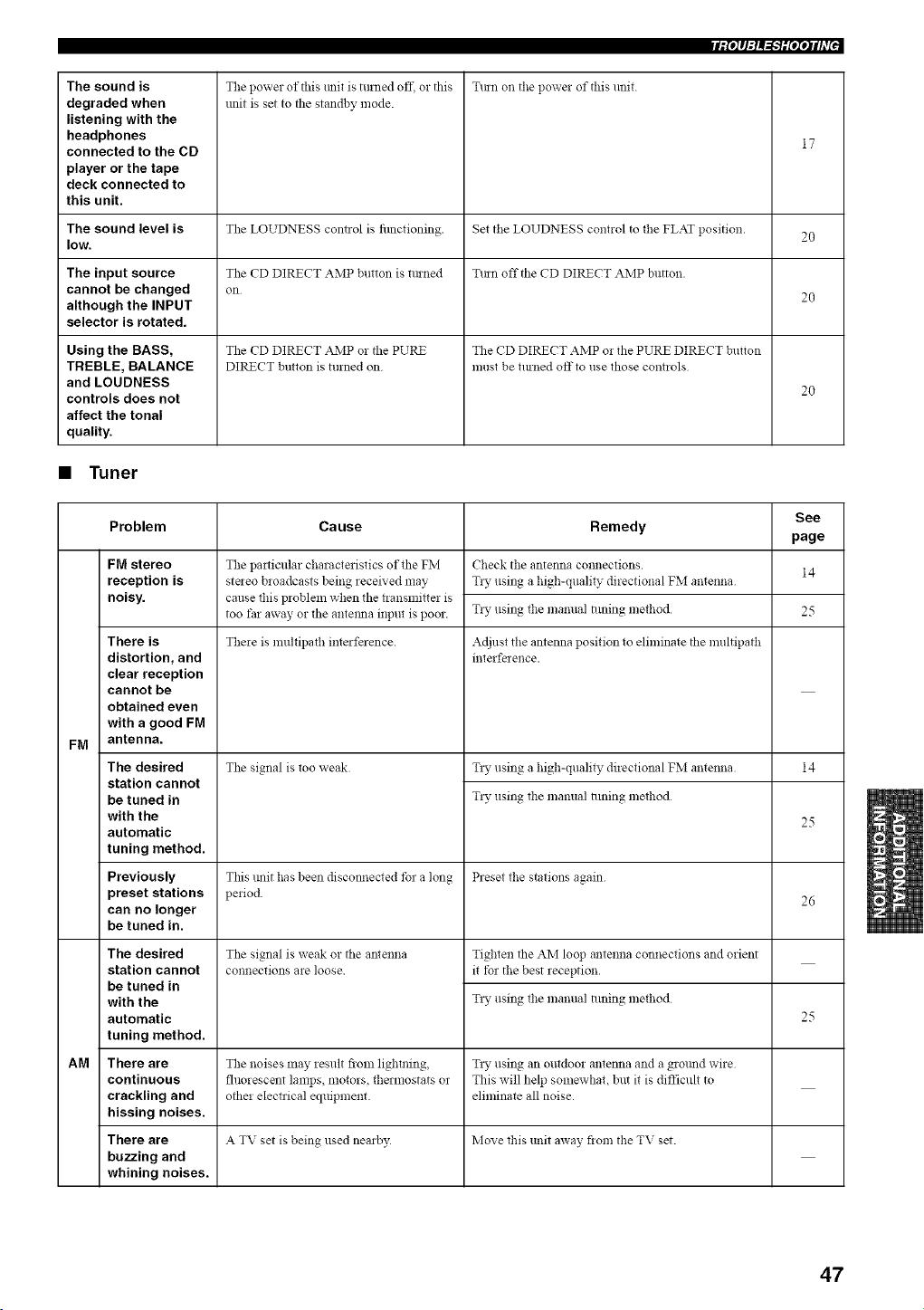
The sound is
degraded when
listening with the
headphones
connected to the CD
player or the tape
deck connected to
this unit.
Tmn on the power of this unit.The power of this trait is turned off. or this
unit is set to tile standby mode.
17
The sound level is The LOUDNESS control is fimctioning. Set the LOUDNESS control to tile FLAT position. 20
low.
The input source The CD DIRECT AMP button is tluned Tmn off the CD DIRECT AMP button.
cannot be changed on 20
although the INPUT
selector is rotated.
Using the BASS, The CD DIRECT AMP o! the PURE The CD DIRECT AMP o* the PURE DIRECT button
TREBLE, BALANCE DIRECT button is turned on must be tinned off to use those controls
and LOUDNESS 20
controls does not
affect the tonal
quality.
• Tuner
See
Problem Cause Remedy
page
14
FM stereo
reception is
noisy.
There is
distortion, and
clear reception
cannot be
obtained even
with a good FM
FM antenna.
The desired
station cannot
be tuned in
with the
automatic
tuning method.
Previously
preset stations
can no longer
be tuned in.
The desired
station cannot
be tuned in
with the
automatic
tuning method.
AM There are
continuous
crackling and
hissing noises.
There are
buzzing and
whining noises.
The particular chanlcteristics of the FM
steleo broadcasts being received may
cause this problem when the t_ansmitter is
too far away or the antemla input is poor.
There is multipath interference.
The signal is too weak
Check the antenna connections.
T_y using a high-quality directional FM antenna
T_y using the maimal auffng method
Adjust the antenna position to eliminate the multipath
interfe_ ence.
T_y using a high-quality directional FM antenna
T_y using the manual tuning method
14
25
Tiffs trait has been discotmected for a long Preset the stations again
period. 26
The signal is weak or the antenna
connections are loose.
Tighten the AM loop antenna connections and orient
it tbr the best reception.
T_y using the manual tuning method
25
The noises may result from lightning, TLv using an outdoor antenna and a grolmd wire
fluorescent lamps, motors, thennostats or This will help somewhat, but it is difficult to
other electrical equipment, eliminate all noise
A TV set is being used nearby Move this unit away flora the TV set.
47
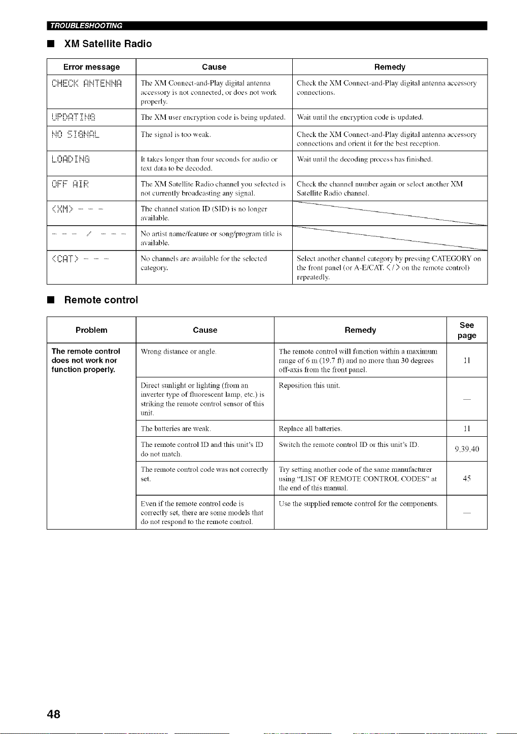
• XM Satellite Radio
Error message
i==i...ii:::'i==i..' ¢"1H "r' i:::' i..i i.. h"i
,...=i H....,...=F.. r'_H i L..HHr"I
i {_::,r'.,l%T 'i' i..h';3
,..q L.'r'_ i .LH'..a
1%..' ...l .l. _...ll _r'_l
'...ll I r"l .l. l".
._"_..=M % ..............
............... ...' ...............
Cause
Tile XM Connect-and-Play digital antenna
accessory is not connected, or does not work
properly.
The XM user encryption code is being updated.
The signal is too weak.
It lakes longer Ihan four seconds for audio or
lexl data Iobc decoded.
The XM Satellite Radio channel you selected is
not currently broadcasting any signal.
The channel station ID (SID) is no longer
available.
No artisl name/fealure or song/program title is
available.
No channels are available for Ihe selected
calegory.
Remedy
Check the XM Connect-and-Play digilal anlcnna accessory
conneclk)ns.
Wait until the encryption code is updated.
Check the XM Connect-and-Play digital antenna accessory
connections and orient it for the best reception.
Wait until the decoding process has finished.
Check the channel number again or selecl another XM
Satellilc Radio channel.
Select anolher channel category by pressing CATEGORY on
the fronl panel (or A-E/CAT. < / > on Ihe remote control)
repealedly.
• Remote control
See
Problem Cause Remedy
page
The remote control W_ong distance m angle The _emote control will function within a maximtm]
does not work nor range of 6 m (197 :_) and no more than 30 degrees 11
function properly, off-axis flora the fiont panel.
Direct sunlight or ligD'ing (flora an Reposition this unit.
inverter type of fluorescent lamp, ere ) is
striking the remote com_ol sensor of this
unit.
The batteries are weak. Replace all battmies. 11
The remote control ID and this unit's ID Switch the remote control ID or this unit's ID.
do not match 9,39.40
The remote com!ol code was not correctly T*y setting another code of the same manufactmer
set. using "LIST OF REMOTE CONTROL CODES" at 45
the end of this manual.
Even if the remote connol code is Use the supplied remote control tbr the components.
correctly set, there are some models that
do not respond to the remote control.
48
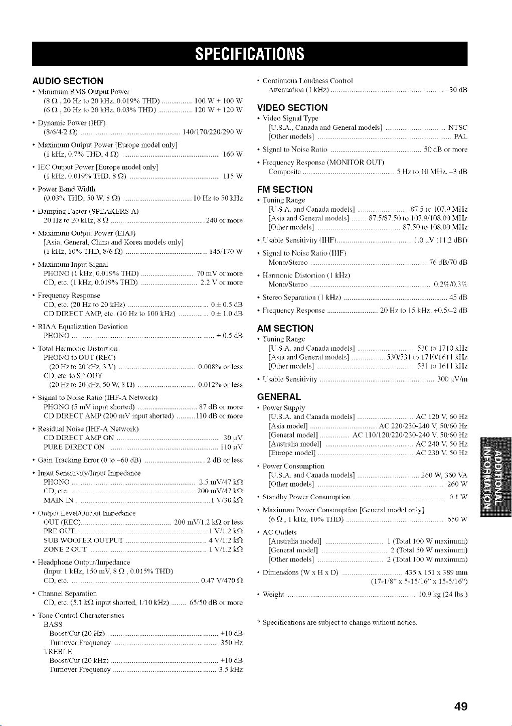
AUDIO SECTION
• Mitfinmm tL\IS Output Powe!
(8 £_, 20 Hz to 20 kHz, 0019% THD) ................ 100 W + 100 W
(6 £_, 20 Hz to 20 kHz, 003% THD) .................. 120 W + 120 W
• Dynamic Power (IHF)
(8/6'4/2 £_) ..................................................... 140/170/220/290 W
• Maxmmm Output Power [Emope model only]
(t kHz, 07% THD, 4 £_) .................................................... 160 W
• IEC Output Power [Europe model only[
(t kHz, 0019% THD, 8 £_) ................................................ 115 W
• Power Band Width
(003% THD, 50 W, 8 £_) ..................................... 10 Hz to 50 kHz
• Damping Factor (SPEAKERS A)
20 Hz to 20 kHz, 8 £_ .................................................. 240 or more
• Maximmn Output Power (EIAJ)
[Asia, General, China and Korea models only[
(1 kHz, 10% THD, 8/6 £_) ........................................... 145/170 W
• Maximmn Input Signal
PHONO (1 kHz, 0.019% THD) ............................ 70 mV or more
CD, etc (1 kHz, 0.019% THD) .............................. 2.2 V or more
• Frequency Response
CD, etc (20 Hz to 20 kHz) ........................................... 0 ± 05 dB
CD DIRECT AMP, etc. (10 Hz to 100 kHz) ................ 0 ± 1 0 dB
• RIAA Equalization Deviation
PHONO ............................................................................ ± 05 dB
• Total Harmonic Distortion
PHONO to OUT (REC)
(20 Hz to 20 kHz, 3 V) ......................................... 0.008°; or less
CD, etc. to SP OUT
(20 Hz to 20 kHz, 50 W, 8 £_) ............................... 0.012% or less
• Signal to Noise Ratio (IHF-A Network)
PHONO (5 mV input sholted) ................................ 87 dB or more
CD DIRECT AMP (200 mV input shorted) .......... 110 dB or more
• Residual Noise (IHF-A Netwolk)
CD DIRECT AMP ON ....................................................... 30 pV
PURE DIRECT ON ........................................................... 110 l_V
• Gain Tracking E_ror (0 to 60 dB) ................................ 2 dB or less
• Inpm Sensitivity/Input hnpedance
PHONO .................................................................. 2.5 mVi47 k£_
CD, etc .................................................................. 200 mVi47 k£_
MAIN IN ........................................................................ 1 Vi30 k£_
• Output LeveliOu_ut hnpedance
OUT (REC) ................................................ 200 lnVi1.2 kQ or less
PRE OUT ...................................................................... 1 Vi1.2 k£_
SUB WOOFER OUTPUT ........................................... 4 Vi1.2 k£_
ZONE 2 OUT .............................................................. 1 Vi1 2 k£_
• Hea@hone Output'Impedance
(Input 1 kHz, 150 m\\ 8 £_, 0.015% THD)
CD, etc ..................................................................... 0.47 V/470 £_
• Channel Separation
CD, etc (5.1 k£_ input sholted, 1/10 kHz) ........ 65/50 dB or more
• Tone Control Characteristics
BASS
Boost/Cut (20 Hz) ........................................................... ±10 dB
Turnover Frequency ........................................................ 350 Hz
TREBLE
Boost/Cut (20 kHz) ......................................................... ±10 dB
Turnover Frequency ....................................................... 35 kHz
• Continuous Loudness Contwl
Attenuation (1 kHz) ............................................................ 30 dB
VIDEO SECTION
• Video Siglml Type
[U.S.A., Canada and Genelal models] ................................ NTSC
[Other models] ....................................................................... PAL
• Signal to Noise Ratio ................................................ 50 dB or more
• Frequency Response (MONITOR OUT)
Composite ................................................. 5 Hz to 10 MHz, 3 dB
FM SECTION
• Tmfing Range
[U.S.A. and Canada models] ........................... 87.5 to 107.9 MHz
[Asia and General models] ........ 87.5/87.50 to 1(t7.9/108.00 MHz
[Other models] ............................................ 87.50 to 108.00 MHz
• Usable Sensitivity (IHF) ........................................ 1.0 [iV (I 1.2 dBf)
• Signal to Noise Ratio (IHF)
Mono/Stereo .............................................................. 76 dB/70 dB
• Harmonic Distortion (1 kHz)
Mono/Stereo ................................................................ 0.2c/_K).3%
• Stereo Separation ( 1 kHz) ....................................................... 45 dB
• Frequency Response ........................... 20 Hz to 15 kHz, +0.5M2 dB
AM SECTION
• Tmfing Range
[U.S.A. and Canada models] .............................. 530 to 1710 kHz
[Asia and General models] ................. 53(!/531 to 1710/161 I kHz
[Other models] ................................................... 531 to 1611 kHz
• Usable Sensitivity ............................................................. 300 !,V/m
GENERAL
• Power Supply
[U.S.A. and Canada models] .............................. AC 120 \; 60 Hz
[Asia model] .................................... AC 220/230-240 \\ 50/60 Hz
[General model] ................ AC 110/120/220/230-240 \-, 50/60 Hz
[Austlalia model] ............................................... AC 240 E 50 Hz
[Europe model[ ................................................... AC 230 V, 50 Hz
• Powe_ Consumption
[U.S.A. and Canada models] ................................. 260 W, 360 VA
[Oflle_ models] ................................................................... 260 W
• Standby Power Consmnption ................................................. 0.1 W
• Maximum Power Consumption [General model only[
(6 t), 1 kHz, 10% THD) .................................................... 650 W
• AC Outlets
[Australia model] ............................... 1 (Total 100 W maxinmm)
[General model] ................................... 2 (Total 50 W maximmn)
[Other models] ................................... 2 (Total 100 W maximmn)
• Dimensions (W x H x D) ................................ 435 x 151 x 389 mm
(17-1/8" x 5-15/16" x 15-5/16")
• Weight .................................................................... 109 kg (24 lbs)
* Specifications are subject to change without notice
49
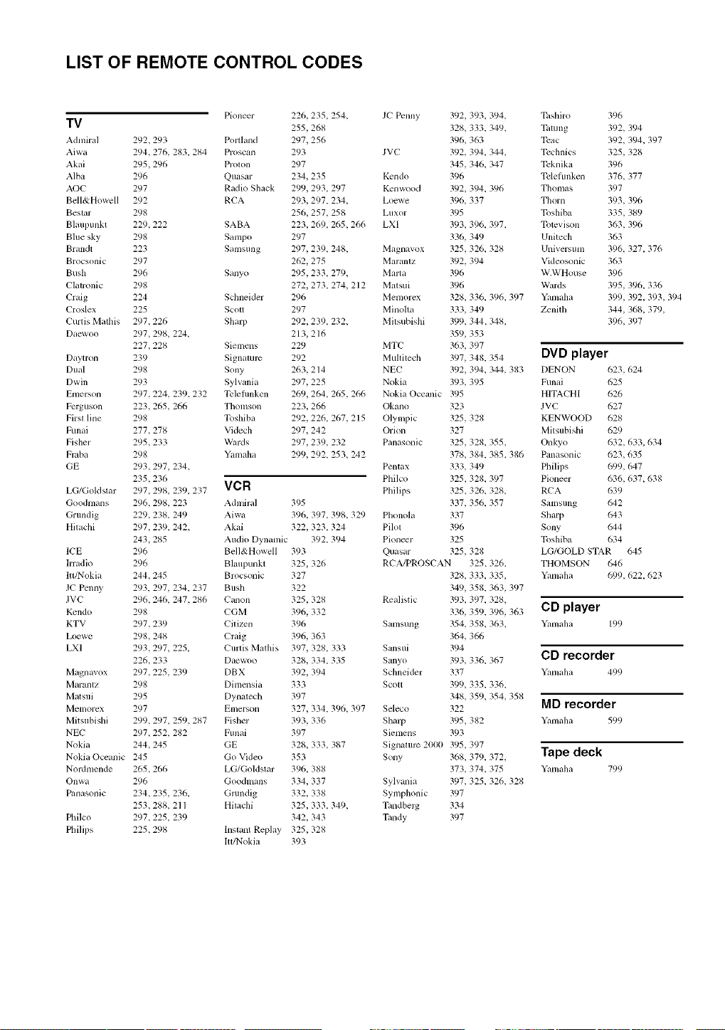
LIST OF REMOTE CONTROL CODES
Pioneer 226,235, 254,
TV 255,268
Admiral 292,293 Portland 297,256
Aiwa 294,276, 283, 284 Proscan 293
Akai 295,296 Prolon 297
Alba 296 Quasar 234,235
AOC 297 Radio Shack 299,293, 297
Bell&Howell 292 RCA 293,297, 234,
Beslar 298 256,257, 258
Blaupunkl 229,222 SABA 223,269, 265,266
Blue sky 298 Sampo 297
Brandl 223 Samsung 297,239, 248,
Brocsonic 297 262,275
Bush 296 Sanyo 295,233, 279,
Clatronic 298 272,273, 274, 212
Craig 224 Sclmeider 296
Croslex 225 Scott 297
Curtis Malllis 297,226 Sharp 292,239, 232,
Dacwoo 297,298, 224_ 213, 216
227,228 Siemens 229
Daytron 239 Signamrc 292
Dual 298 Sony 263, 214
Dwin 293 Sylvania 297,225
Emerson 297,224, 239,232 Tcleflmken 269,264, 265,266
Fcrguson 223,265,266 Thomson 223,266
Firsl line 298 Toshiba 292,226, 267, 215
Funai 277,278 Videch 297,242
Fisher 295,233 Wards 297,239, 232
Fraba 298 Yamaha 299,292, 253, 242
GE 293,297, 234,
235,236
LG/Goldstar 297,298, 239, 237 VCR
Goodmans 296,298, 223 Admiral 395
Grundig 229,238, 249 Aiwa 396, 397, 398, 329
Hilachi 297,239, 242, Akai 322, 323, 324
243,285 Audio Dynamic 392, 394
lCE 296 Bell&Howell 393
lrradio 296 Blaupunkl 325,326
ltl!Nokia 244,245 Brocsonic 327
JC Penny 293, 297, 234, 237 Bush 322
JVC 296,246, 247,286 Canon 325,328
Kcndo 298 CGM 396, 332
KTV 297,239 Citizen 396
Loewe 298,248 Craig 396, 363
LXI 293,297, 225_ Curtis Mathis 397, 328, 333
226,233 Daewoo 328, 334, 335
Magnavox 297,225,239 DBX 392, 394
Maranlz 298 Dimensia 333
Malsui 295 Dynatech 397
Memorex 297 Emcrson 327, 334, 396, 397
Mitsubishi 299,297, 259,287 Fisher 393, 336
NEC 297,252, 282 Funai 397
Nokia 244,245 GE 328, 333, 387
N0kia Oceanic 245 Go Video 353
Nordmende 265,266 LG/Goldstar 396, 388
Onwa 296 Goodmans 334, 337
Panasonic 234,235,236, Glundig 332, 338
253,288, 211 Hitachi 325,333, 349,
Philco 297,225,239 342, 343
Philips 225,298 lnslant Replay 325,328
ltt/Nokia 393
JC Penny 392, 393, 394,
328, 333, 349,
396, 363
JVC 392, 394, 344,
345,346, 347
Kcndo 396
Kcnwood 392, 394, 396
Loewe 396, 337
Luxor 395
LXI 393, 396, 397,
336, 349
Magnavox 325,326, 328
Maranlz 392, 394
Marta 396
Matsui 396
Memorcx 328, 336, 396, 397
Minolta 333, 349
Milsubishi 399, 344,348,
359, 353
MTC 363, 397
Muhitech 397, 348, 354
NEC 392, 394, 344, 383
Nokia 393, 395
Nokia Oceanic 395
Okano 323
Olympic 325,328
Orion 327
Panasonic 325,328. 355.
378, 384, 385_ 386
Pentax 333, 349
Philco 325,328, 397
Philips 325,326, 328,
337, 356, 357
Phonola 337
Pilot 396
Pioneer 325
Quasar 325,328
RCA/PROSCAN 325,326,
328, 333, 335,
349, 358, 363, 397
Realistic 393, 397, 328,
336, 359, 396, 363
Samsung 354, 358, 363_
364, 366
Sansui 394
Sanyo 393, 336, 367
Schneider 337
Scott 399, 335, 336,
348, 359_ 354, 358
Seleco 322
Sharp 395,382
Siemens 393
Signamrc 2000 395,397
Sony 368, 379, 372,
373, 374, 375
Sylvania 397, 325, 326, 328
Symphonic 397
Timdbelg 334
Tandy 397
Tilshiro 396
Tatung 392, 394
Tcac 392, 394, 397
Tcchnics 325,328
Tcknika 396
Tcleflmken 376, 377
Thom+_s 397
Thorn 393,396
Toshiba 335,389
Tomvison 363,396
Unitech 363
Universum 396, 327, 376
Videosonic 363
W.WHouse 396
Wards 395,396, 336
Yamaha 399, 392, 393,394
Zenith 344,368, 379,
396, 397
DVD player
DENON 623,624
Funai 625
HlTACHl 626
JVC 627
KENWOOD 628
Mitsubishi 629
Onkyo 632,633,634
Panasonic 623,635
Philips 699,647
Pioneer 636,637,638
RCA 639
Samsung 642
Sharp 643
Sony 644
Toshiba 634
LG/GOLD STAR 645
THOMSON 646
Yamaha 699,622,623
CD player
Yanmha 199
CD recorder
Yamaha 499
MD recorder
Yanmha 599
Tape deck
Yamaha 799

This product mainly uses lead-free solder.
© 2005 YAMAHA CQRPOP_FION All rights reserved.
YAMAHA ELECTRONICS CORPORATION, USA 6660 ORANGETHORPE AVE., BUENA PARK, CALIF. 90620, U.S.A.
YAMAHA CANADA MUSIC LTD. 135 MILNER AVE., SCARBOROUGH, ONTARIO M1S 3R1, CANADA
YAMAHA ELECTRONIK EUROPA G.m.b.H. SIEMENSSTR. 22-34, 25462 RELMNGEN SEI HAMBURG, GERMANY
YAMAHA ELECTRONIQUE FRANCE S.A. RUE AMBROISE CROIZAT BP70 CROISSY-BEAUBOURG 77312 MARNE-LA-VALLEE CEDEX02, FRANCE
YAMAHA ELECTRONICS (UK) LTD. YAMAHA HOUSE, 200 RICKMANSWORTH ROAD WATFORD, HERTS WD18 7GQ, ENGLAND
YAMAHA SCANDINAVIA A.B. J A WETTERGRENS GATA 1, BOX 30053, 400 43 VASTRA FROLUNDA, SWEDEN
YAMAHA M USIC AUSTRALIA PTY, LTD. 17-33 MARKET ST., SOUTH MELBOURNE, 3205 VIC., AUSTRALIA
YAMAHA CORPORATION
Printed in Malaysia C WG04970