
Loading ...
Loading ...
Loading ...
LOOSEN
TIGHTEN
CONTROL
ARM
MITER MITER
LOCKHANDLE TABLE
Fig. 8
DUST GUIDE
See Figure 9.
To install the dust guide, place the end marked
INSERT over the exhaust port in the upper blade
guard. Turn the guide so that the open end is facing
down or toward the rear of the saw.
EXHAUST
PORT
DUSTGUIDE
DUSTBAG
Fig. 9
DUST BAG
See Figure 9.
The dust bag fits over the exhaust port on the upper
blade guard. To install the dust bag, remove the dust
guide from the exhaust port. Then, squeeze the two
metal clips to open the mouth of the bag and slide the
bag on the exhaust port. Release the clips. The metal
ring in the bag should lock in between the grooves on
the exhaust port. For more efficient operation, empty
the dust bag when no more than half full. This will
permit better air flow through the bag.
TO INSTALL BLADE
See Figures 10, 11, and 12.
A
WARNING: A 10 in. blade isthe maximum
blade capacity of your saw. Never use a blade
that is too thick to allow outer blade washer to
engage with the flats on the spindle. Larger
blades will come in contact with the blade
guards, while thicker blades will prevent the
blade screw from securing the blade on the
spindle. Either of these situations could result in
a serious accident and can cause serious
personal injury.
• Unplug your saw.
_1, WARNING: Failureto unplugyour saw could
result in accidental starting causing possible
serious personal injury.
Push down on the saw arm and pull out the lock
pin to release saw arm. Raise saw arm to its full
raised position. Be cautious, saw arm is spring
loaded to raise.
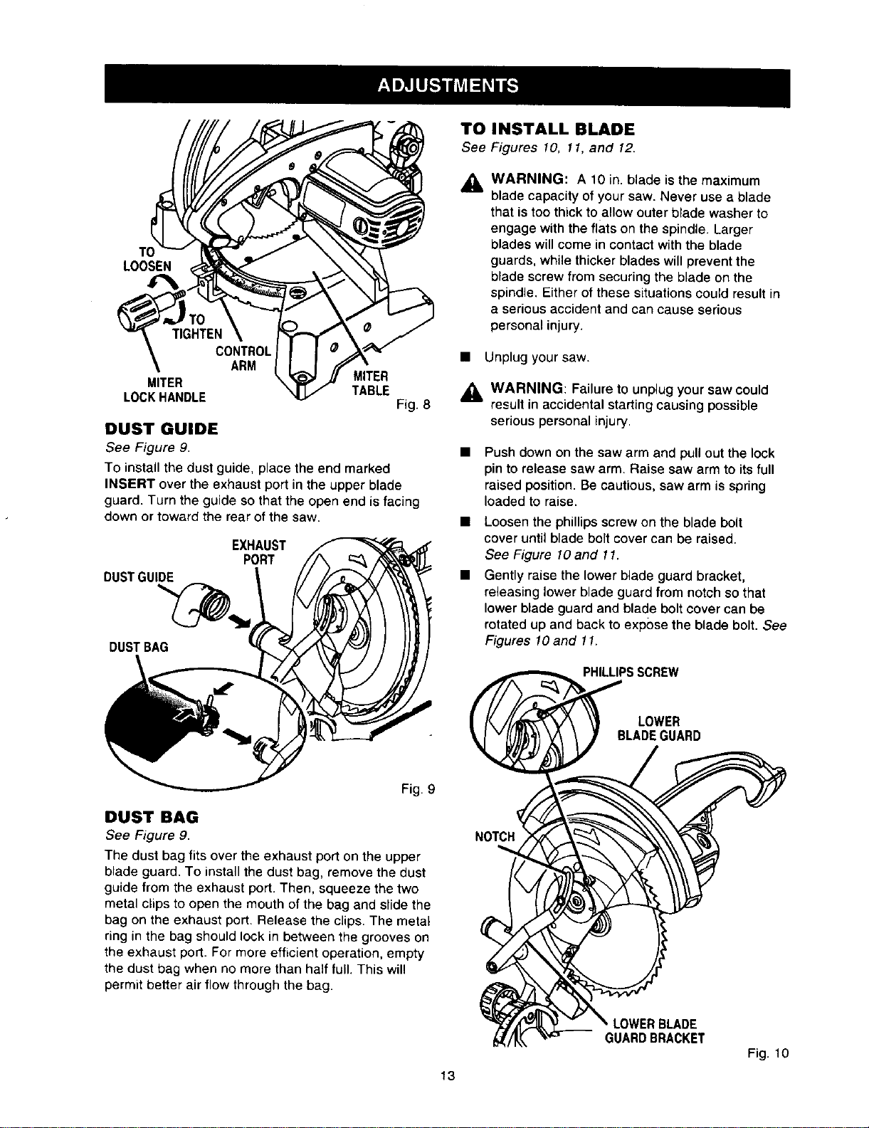
Loosen the phillips screw on the blade bolt
cover until blade bolt cover can be raised.
See Figure 10 and 11.
Gently raise the lower blade guard bracket,
releasing lower blade guard from notch so that
lower blade guard and blade bolt cover can be
rotated up and back to expose the blade bolt. See
Figures lO and 11.
PHILLIPSSCREW
LOWER
BLADEGUARD
LOWERBLADE
GUARDBRACKET
Fig. 10
13
Loading ...
Loading ...
Loading ...