
Hardwire Kit
DSH-HWK | USER MANUAL
Constant power for your dashcam.

2

NOTES AND INSTALLATION ..........................................................................................4
1 PRODUCT INFORMATION ................................................................................... 5
1.1 INTRODUCTION ..............................................................................................5
1.2 FEATURES ......................................................................................................... 5
1.3 PACKAGE CONTENTS ...................................................................................67
2 BATTERY DRAIN PROTECTION .......................................................................... 7
2.1 SETTING THE CUT OFF VOLTAGE .............................................................7
2.2 VEHICLE BATTERY LEAD ACID STATES AND CAPACITY .....................8
3 INSTALLATION ....................................................................................................... 9
3.1 CONNECTING HARDWIRE KIT TO YOUR DASHCAM ........................... 10
3.1.1 ATTACHING THE USB CONNECTOR TO THE DASHCAM ........10
3.2 ROUTING THE OUTPUT CABLE
FROM THE DASHCAM TO THE FUSE BOX ..............................................1011
3.2.1 INSTALLING THE OUTPUT CABLES IN VEHICLE .......................1114
3.2.2 HOUSING THE OUTPUT CABLE .....................................................1415
3.3.1 CONNECTING TO THE FUSE BOX ................................................. 1617
3.3.2 CONNECTING TO GROUND ............................................................ 18
4 SPECIFICATIONS .................................................................................................. 19
5 WARRANTY TERMS & CONDITIONS ................................................................ 20
6 NOTES ........ ............................................................................................................. 21-22
TABLE OF CONTENTS
3

NOTES AND INSTALLATION
IMPORTANT: REFER TO YOUR VEHICLE OWNER’S MANUAL
TO DETERMINE:
Location of the fuse box
How to access the fuse box
The type of fuse tap required
It is highly recommended that you have a quick read of the installation
instructions in this user guide. If you are not comfortable with the
process please seek further assistance from an authorised technician.
Since power to your dashcam will be running via a power cable from
the fuse box you will need to determine your vehicle’s fuse box location.
Most vehicles have a fuse box underneath the dashboard on the driver’s
side which is easily accessible below the steering column (behind a
removable panel). However the location does vary between vehicle make
and model.
There are 4 types of fuse tap cables included in this kit. Check to see if
these fuses suit your vehicle’s fuse box. If none are suitable you will need
to purchase the correct fuse to attach the hardwire kit to your vehicle’s
power source.
Note: You may need to consult your vehicle manufacturer for
instructions on how to remove vehicle ittings (example A pillar
cover) for routing the hardwire kit cables inside your vehicle and for
where airbags are located so that these are not obstructed in case of
deployment by routed cables.
Installation of DSH-HWK is recommended to be performed by a
technician. Working with your vehicle’s power system can be dangerous
to both you and your vehicle if you do not know what you are doing.
If you have any doubts please consult a professional. Dashmate
recommends professional installation only of this dashcam hardwire kit.
IMPORTANT: Refer to your dashcam owner’s manual for initial
installation of your dashcam in your vehicle.
DSH-HWK is a kit that allows for the provision of constant power from
your vehicle battery to your dashcam. Any issues with your dashcam
should be referred to your dashcam’s manufacturer.
4

1 PRODUCT INFORMATION
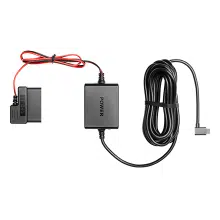
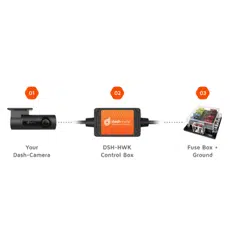
Get constant power for your dashcam. DSH-HWK connects to your
vehicle battery through your vehicle’s fuse box and provides constant
power to your dashcam when the engine is turned off. It includes several
fuse tap options that suit most vehicles* and your dashcam connects
to the hardwire kit with either the Micro USB or Mini USB connectors
included. For latest manual and product updates please visit our
website.
*A suitable fuse tap cable will need to be purchased separately if the
fuse tap cable options included in this pack are not suitable for your
vehicle’s fuse box.
1.1 INTRODUCTION
Thank you for purchasing a DSH-HWK Hardwire Kit. DSH-HWK is a
simple plug and play solution to hardwire your Dashmate dashcam or
any other dashcam with a Mini USB and Micro USB connection. Please
read through these instructions carefully before attempting to install or
use this product.
1.2 FEATURES
Universal kit suits Dashmate and all other dashcams with Mini USB
or Micro USB connections.
Can be installed in cars and trucks as is compatible with 12V and
24V batteries.
Provides constant power to your dashcam when your vehicle is
turned off.
Is protected with Battery Drain Protection to safeguard your
dashcam from draining your vehicle’s battery. Your battery will stop
providing power to your dashcam if your battery level gets too low.
Includes 4 different fuse tap cables – simply plug the required fuse
tap cable into the vehicle’s fuse box to provide your dashcam with its
own power supply without engaging the cigarette socket.
Includes both Mini USB and Micro USB connectors for connection to
all Dashmate dashcam models
5
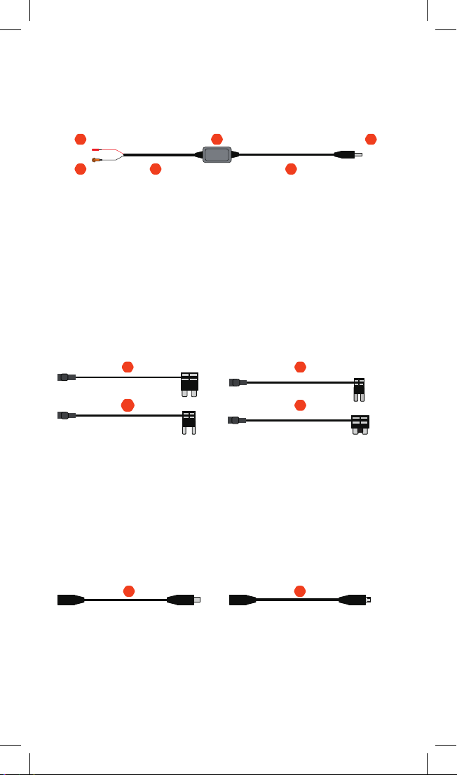
1.3 PACKAGE CONTENTS
HARDWIRE KIT
1. Red Input Connector
2. Black Input Connector
3. Input Cable
4. Control Box with Adhesive Pad
5. Output Cable
6. Output Connector
VEHICLE FUSE OPTIONS
(USE ONLY ONE OPTION FOR INSTALLATION)
7. ATS (Standard) Fuse Cable
8. Mini Fuse Cable
9. Micro2 Fuse Cable
10. Micro Fuse Cabler
DASHCAM OUTPUT CONNECTOR OPTIONS
(USE ONLY ONE OPTION FOR INSTALLATION)
11. Mini USB Cable
12. Micro USB Cable
0601
02 03
04
05
Red Input
Black Input
Twin 22 AWG Cables Twin 22 AWG Cables
DC3.5x1.35
Flat Output
07
08
09
10
1211
6
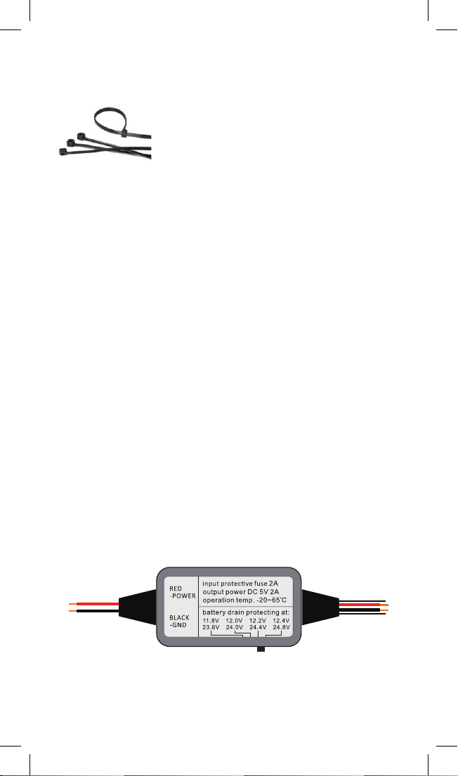
1.3 PACKAGE CONTENTS CONT’D
ACCESSORIES
1. Cable Ties x 4
2 BATTERY DRAIN PROTECTION
The Hardwire Kit will protect your dashcam from draining your vehicle’s
battery. If your vehicle’s battery voltage gets too low, DSH-HWK will
stop powering your camera to save power. You will never have to worry
about your car’s battery dying when DSH-HWK is in use.
2.1 SETTING THE CUT OFF VOLTAGE
Set the cut off voltage according the temperature and the capacity
you’d like to consume before the hardwire kit cuts off the output.
There are 4 protecting bands set in the hardwire kit, you can switch
according your requirement.
For 12V Batteries
The protecting voltages are 11.8V / 12.0V / 12.2V / 12.4V.
12.2V recommended for most users in general driving conditions.
For 24V Batteries
The protecting voltages are 23.6V / 24.0V / 24.4V / 24.8V.
24.4V recommended for most users in general driving conditions.
The hardwire kit will identify the lead acid battery type automatically
(12V or 24V) and protect your battery from draining accordingly.
7

2.2 VEHICLE BATTERY LEAD ACID
STATES AND CAPACITY
Use the below table to assist in determining your desired voltage cut off
level for battery drain protection.
For example if the temperature is 38°C and you want to keep a 75%
lead acid state capacity remaining in your battery when the hardwire kit
cuts off output (meaning the battery voltage is approximately 12.402V)
the cut off voltage should be set at the 12.4V band. This means there
will be 25% capacity in your vehicle battery which will be used for your
dashcam while your vehicle is parked.
Using a 50Wh lead acid battery for an example, the 25% consumption
will support approximately 50 hours of dashcam use.
NOTE: Please be advised that the above table is to be used as a
reference guide only in order to determine an appropriate voltage
selection dependent on the battery age and condition.
Temperature Lead Acid State & Voltage (Volt)
C 100% 75% 50% 25% 0
-7 12.794 12.594 12.384 12.204 12.034
-1 12.77 12.57 12.36 12.18 12.01
4 12.746 12.546 12.336 12.156 11.986
10 12.722 12.522 12.312 12.132 11.962
16 12.698 12.498 12.288 12.108 11.938
21 12.674 12.474 12.264 12.084 11.914
27 12.65 12.45 12.24 12.06 11.89
32 12.626 12.462 12.216 12.036 11.866
38 12.602 12.406 12.192 12.012 11.842
43 12.578 12.378 12.168 11.988 11.818
49 12.554 12.354 12.144 11.964 11.794
8
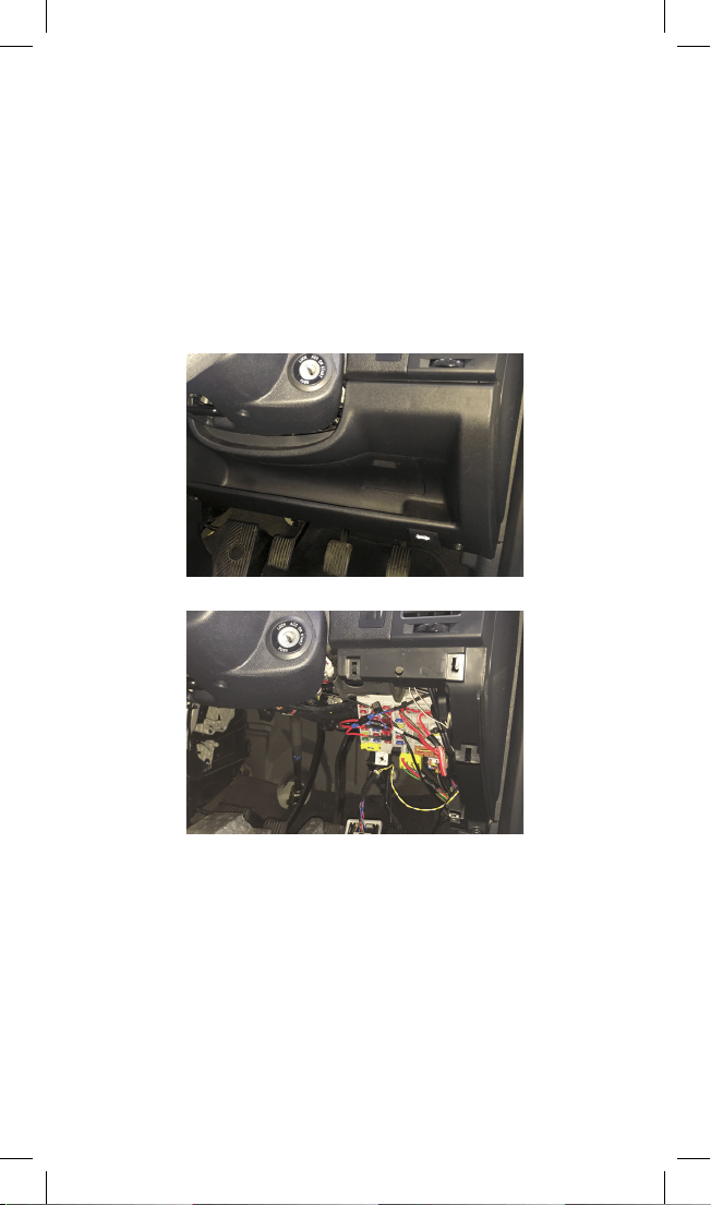
3 INSTALLATION
The location of the vehicle’s fuse box varies from vehicle make and
model. Locations may include underneath the driver’s side dashboard,
behind the glove box and underneath the central console. Where in
doubt, always refer to your vehicle owner’s manual to determine the
location of the fuse box in your vehicle.
NOTE: The images in this installation were taken for a vehicle where
the fuse box is located under the driver’s side dashboard (Fig. 1, 2)
and should be used as a guide only for a DIY installation. To ensure
proper installation Dashmate recommends DSH-HWK be installed by a
professional technician.
There are 2 main stages in the hardwire kit installation
• Connecting output cable to your dashcam
• Connecting input cables to your fuse box and grounding
NOTE: Determine the location of your vehicle’s fuse box before
commencing the installation of the hardwire kit. Where in doubt, refer
to the vehicle owner’s manual.
FIG. 2
FIG. 1
9
3.1 CONNECTING HARDWIRE KIT TO YOUR DASHCAM
IMPORTANT: Refer to your dashcam owner’s manual for initial
installation of your dashcam in your vehicle.
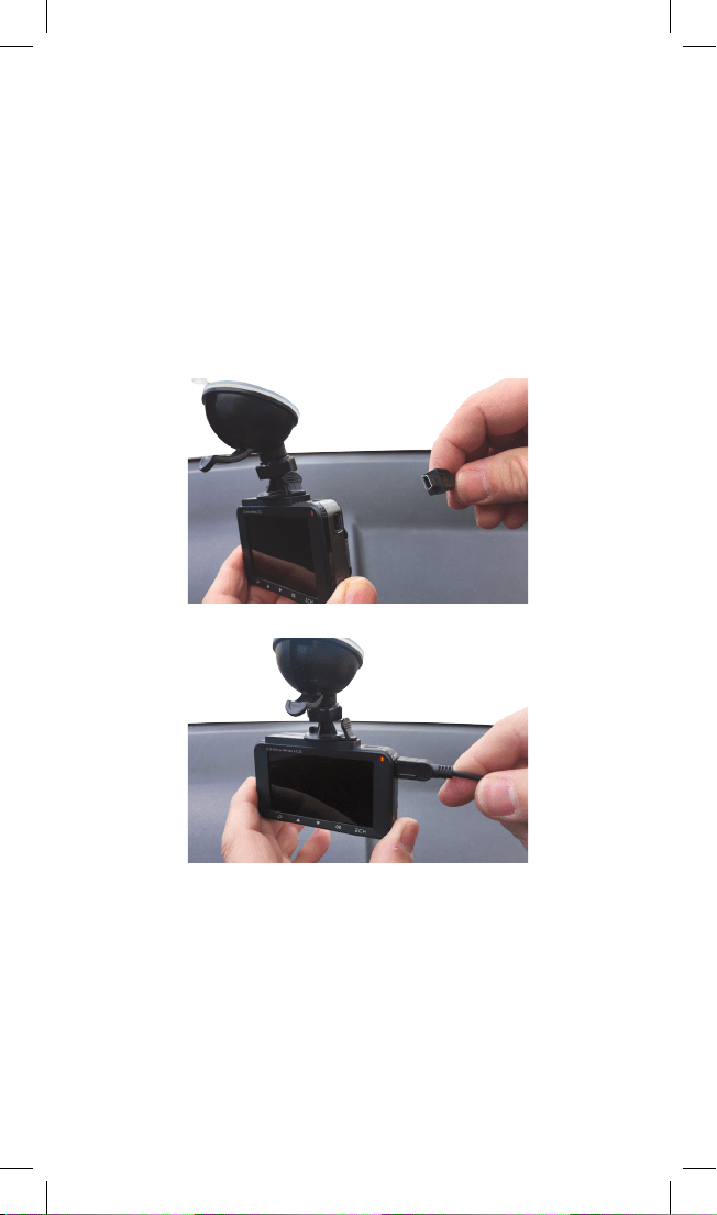
3.1.1 ATTACHING THE USB CONNECTOR TO THE DASHCAM
1. Two dashcam connector cables are included with DSH-HWK – one
with a Mini USB plug and one with a Micro USB plug. Determine
the connection interface type on your dashcam and then select the
appropriate USB connector cable. (Fig 3)
2. Insert the USB connector cable to your dashcam (Fig 4)
3.2 ROUTING THE OUTPUT CABLE FROM THE DASHCAM
TO THE FUSE BOX
NOTE: You may need to consult your vehicle manufacturer for
instructions on how to remove vehicle ittings (example A pillar
cover) for routing the hardwire kit cables inside your vehicle and for
where airbags are located so that these are not obstructed in case of
deployment by routed cables.
FIG. 4
FIG. 3
10
3.2 ROUTING THE OUTPUT CABLE FROM THE DASHCAM
TO THE FUSE BOX CONT’D
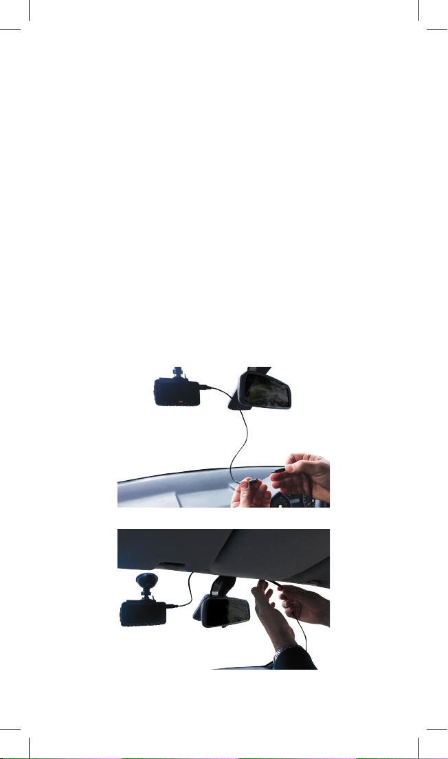
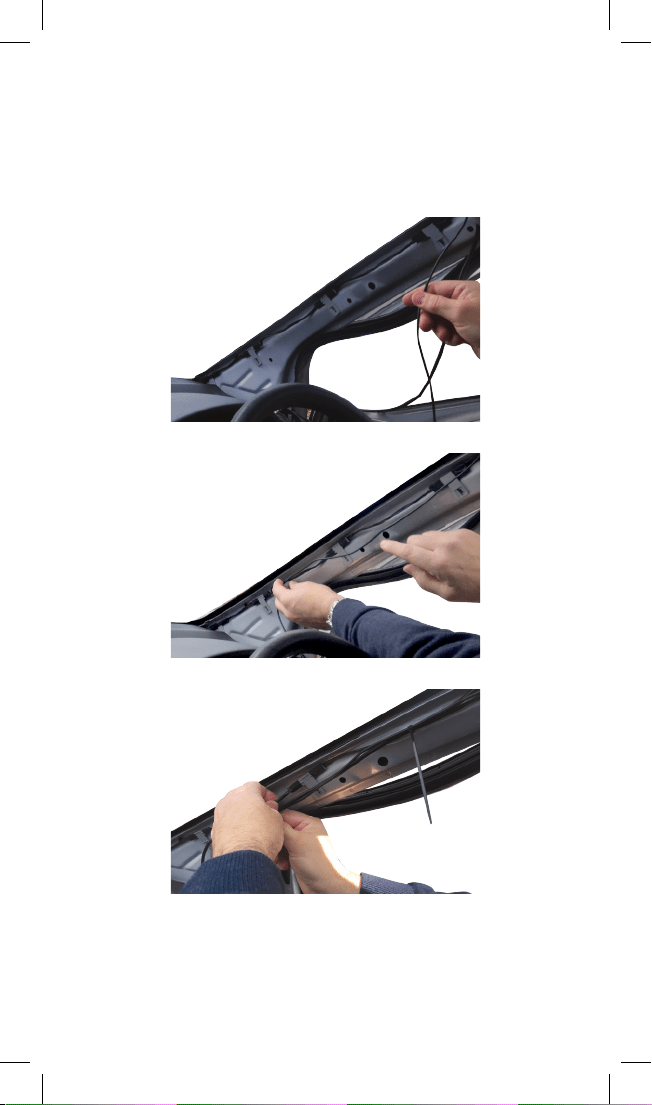
3.2.1 INSTALLING THE OUTPUT CABLES IN VEHICLE
1. Once the USB connector cable is attached to your dashcam, it then
needs to be connected to the hardwire kit’s output cable. (Fig 5)
2. The hardwire kit output cable will then need to be recessed into the
roof lining where it meets the edge of the windscreen to conceal the
cable (Fig 6a, 6b)
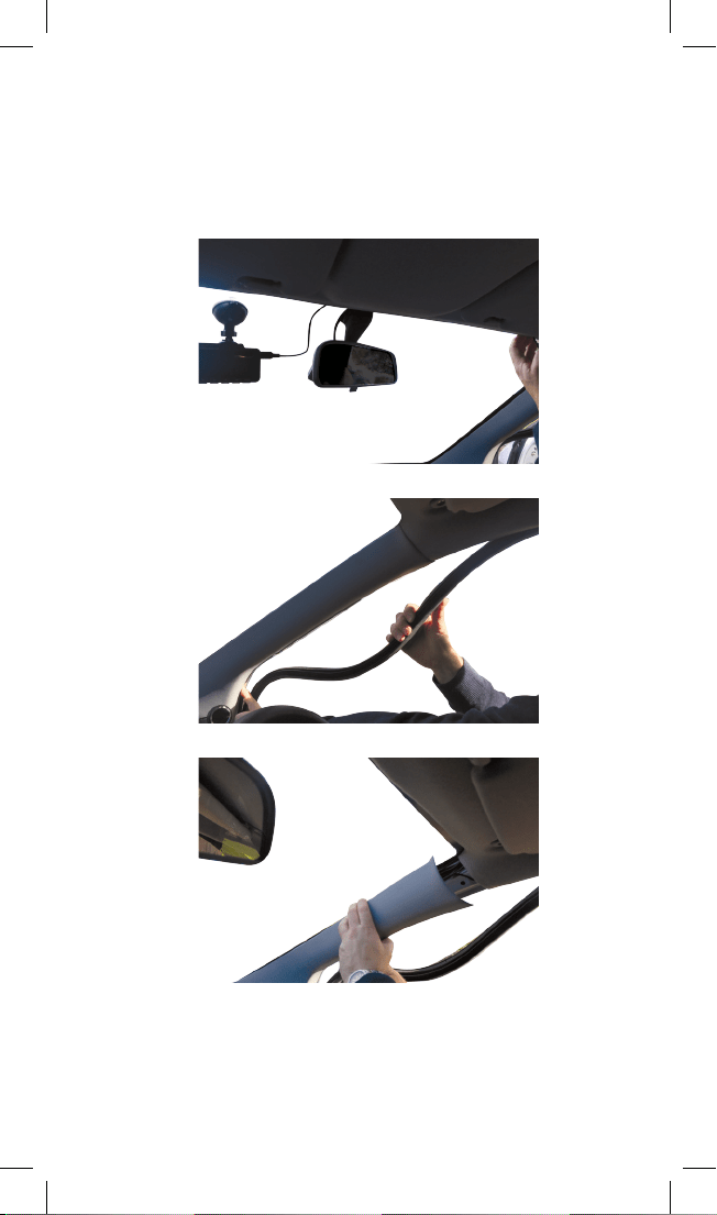
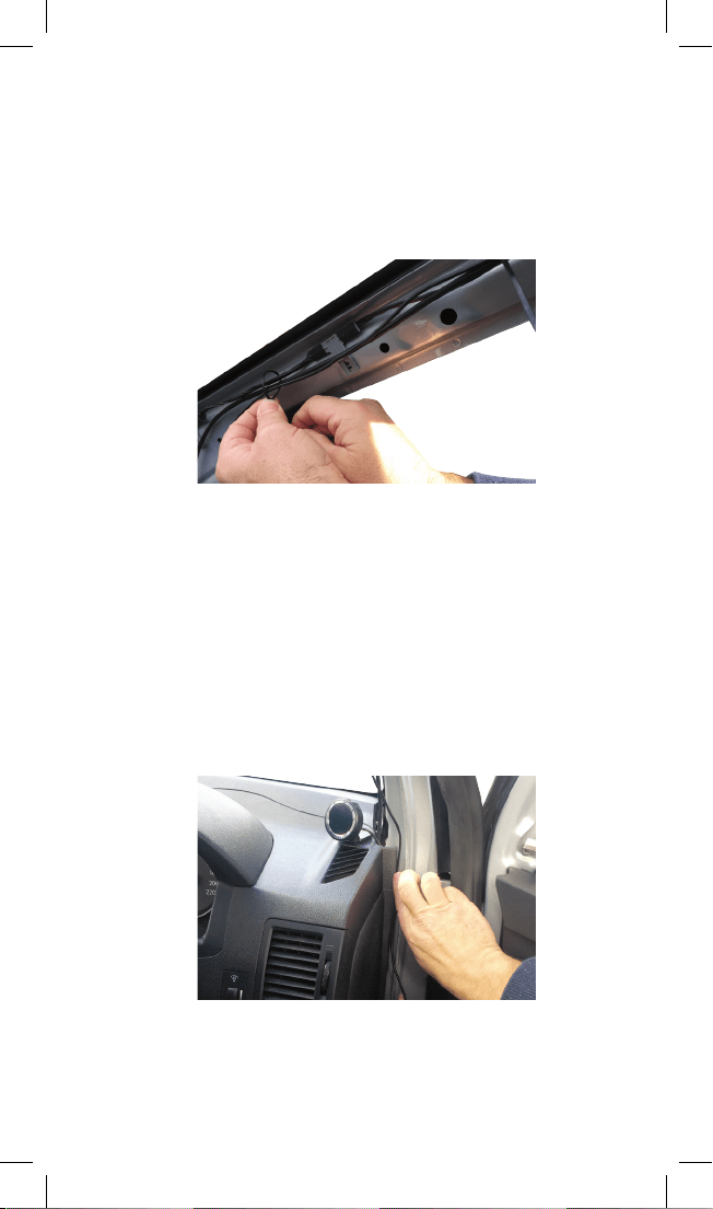
3. At the farthest end of the roof lining the output cable needs to then
be routed along the A pillar that is closest to the fuse box of the
vehicle. You will need to remove the door seal (Fig 7) and A pillar
cover (Fig 8) to route the cable (Fig 9a, 9b). Route the cable all the
way down to the end of the A pillar where it meets the dashboard.
4. Use the provided cable ties to attach the output cable to any
existing cable(s) that may be housed in the A pillar (Fig 10a, 10b).
NOTE: The A pillar used to route the cable is not always the driver’s side
one as shown. Refer to the vehicle owner’s manual to determine location
of fuse box in your vehicle. The output cable needs to be routed in the
A-pillar closest to the fuse box.
FIG. 6a
FIG. 5
11
3.2 ROUTING THE OUTPUT CABLE FROM THE DASHCAM
TO THE FUSE BOX CONT’D
3.2.1 INSTALLING THE OUTPUT CABLES IN VEHICLE CONT’D
FIG. 7
FIG. 6b
FIG. 8
12
3.2 ROUTING THE OUTPUT CABLE FROM THE DASHCAM
TO THE FUSE BOX CONT’D
3.2.1 INSTALLING THE OUTPUT CABLES IN VEHICLE CONT’D
FIG. 9b
FIG. 9a
FIG. 10a
13
3.2 ROUTING THE OUTPUT CABLE FROM THE DASHCAM
TO THE FUSE BOX CONT’D
3.2.1 INSTALLING THE OUTPUT CABLES IN VEHICLE CONT’D
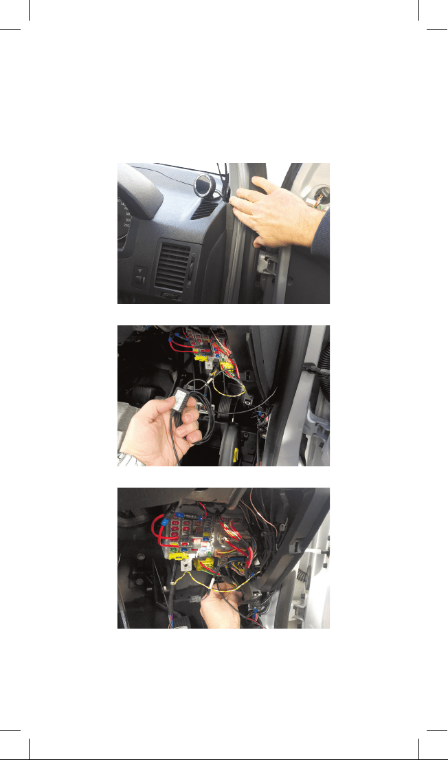
3.2.2 HOUSING THE OUTPUT CABLE
1. Where the output cable from the A pillar meets the side of the
dashboard, the output cable will then need to be routed towards the
direction of the fuse box by concealing the cable along the side of
the vehicle dash (Fig 11a, 11b).
2. Any excess output cable length can be wrapped and held together
with a cable tie when it reaches the fuse box (Fig 12)
3. Tuck away any excess output cable behind the fuse box (Fig 13)
4. If required, peel off the control box label to attach the control box to
the vehicle (near the fuse box) with the adhesive tape.
FIG. 11a
FIG. 10b
14
3.2 ROUTING THE OUTPUT CABLE FROM THE DASHCAM
TO THE FUSE BOX CONT’D
3.2.2 HOUSING THE OUTPUT CABLE
FIG. 12
FIG. 11b
FIG. 13
15
3.2 CONNECTING HARDWIRE KIT TO YOUR FUSE BOX
AND GROUNDING
3.3.1 CONNECTING TO THE FUSE BOX
NOTE: Refer to your vehicle’s fuse layout panel to determine the
permanent power fuse for constant power feed. The fuse cable needs to
be connected to the 12V/24V battery feed.
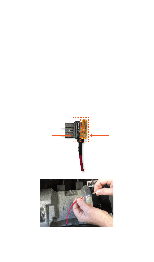
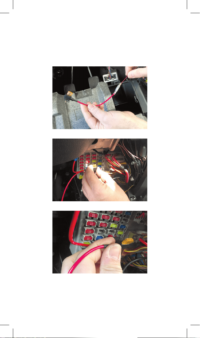
1. Determine the fuse tap cable required for connection to your fuse
box. Where in doubt refer to the vehicle owner’s manual.
2. Place the vehicle fuse in the fuse tap cable. Note the correct position
location for both the vehicle fuse and the hardwire kit fuse in the
fuse tap cable (Fig 14).
3. Locate the input cable and connect the fuse tap cable to the red
input connector (Fig 15a, 15b). Ensure connection is secure.
4. Insert the fuse tap into the fuse box (Fig 16a, 16b).
5. Tuck away any excess red input cable behind the fuse box.
NOTE: To determine constant power feed fuse use a voltage meter.
16
FIG. 15a
FIG. 14
Hardwire Kit fuse
Connect vehicle fuse
3.2 CONNECTING HARDWIRE KIT TO YOUR FUSE BOX
AND GROUNDING CONT’D
3.3.1 CONNECTING TO THE FUSE BOX CONT’D
FIG. 16a
FIG. 15b
FIG. 16b
17
3.2 CONNECTING HARDWIRE KIT TO YOUR FUSE BOX
AND GROUNDING CONT’D
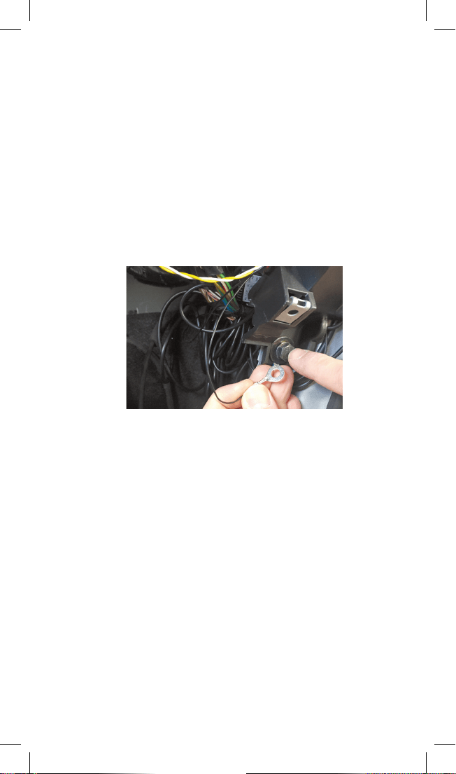
3.3.2 CONNECTING TO GROUND
1. Locate earth terminal/bolt or any vehicle bolt accessible that is
mounted to the chassis of the vehicle or any metal part of the
vehicle - located near the vehicle fuse box (Fig (17).
2. Feed black input wire eyelet into bolt and screw bolt back on
existing location.
3. Tuck away any excess input cable behind the fuse box.
NOTE: The black earth cable needs to be connected to the vehicle
chassis otherwise it will not earth out.
FIG. 17
18

4 SPECIFICATIONS
HARDWIRE KIT: CABLES
RED INPUT CONNECTOR BULLET PLUG OD4MM
BLACK INPUT CONNECTOR ROUND RING TERMINAL, NICKEL PLATED,
OD10MM ID6MM L20MM
INPUT CABLE TWIN CABLES (RED: 12V/24V POWER; BLACK:
GROUND), 2X22AWG, CONDUCTOR, SR-PVC
INSULATION, PVC JACKET, UL1015/2586, 1M,
150MM CLEARANCE
OUTPUT CABLE TWIN CABLES, 2X22AWG CONDUCTOR; SR-PVC
INSULATION, PVC JACKET; UL/1007/2464, 3M
OUTPUT CONNECTOR DC3.5X1.35 FEMALE RECEPTOR
HARDWIRE KIT: CONTROL BOX
FLAME RETARDANT ABS 94V0, CONTAINS DC-DC CONVERTER
INPUT VOLTAGE MIN 10V
INPUT VOLTAGE MAX 32V
OUTPUT VOLTAGE NO LOAD: 5.2V
0.5A LOAD: 5.1V
1A LOAD: 5V
OUTPUT POWER DC 5V 2A
BATTERY DRAIN PROTECTION
BANDS
11.8V/23.6V
12.0V/24.0V
12.2V/24.4V
12.4V/24.8V
OTHER PROTECTION REVERSE POLARITY; SHORT CIRCUIT; OVER
TEMPERATURE; OVER VOLTAGE; OVER LOAD
WORKING TEMP -20°C TO 65°C
FUSE CABLES
ATS (STANDARD) FUSE
CABLE
CABLE WITH 5A ATS (STANDARD) FUSE, L125MM
MINI FUSE CABLE CABLE WITH 5A MINI FUSE, L125MM
MICRO2 FUSE CABLE CABLE WITH 5A MICRO2 FUSE, L125MM
MICRO FUSE CABLE CABLE WITH 5A MICRO FUSE, L125MM
ACCESSORIES
MINI USB CABLE DC3.5X1.35 MALE TO MINI USB ADAPTOR,
L400MM
MICRO USB CABLE DC3.5X1.35 MALE TO MICRO USB ADAPTOR,
L400MM
CABLE TIES QUICK FIX CABLE TIE, BLACK PA66, UL94V2, -20°C
TO 105°C, 8KGs, W2.5MM L80MM
19

5 WARRANTY TERMS & CONDITIONS
Our goods come with guarantees that cannot be excluded under
the Australian & New Zealand Consumer Law. You are entitled to a
replacement or refund for a major failure and for compensation for any
other reasonably foreseeable loss or damage. You are also entitled to
have the goods repaired or replaced if the goods fail to be of acceptable
quality and the failure does not amount to a major failure.
This warranty is provided in addition to your rights under the Australian
& New Zealand Consumer Law.
Directed Electronics warrants that this product is free from defects
in material and workmanship for a period of 12 months from the date
of purchase or for the period stated on the packaging. This warranty
is only valid where you have used the product in accordance with any
recommendations or instructions provided by Directed Electronics. This
warranty excludes defects resulting from alterations of the product,
accident, misuse, abuse or neglect.
In order to claim the warranty, you must return the product to the
retailer from which it was purchased or if that retailer is part of a
National network, a store within that chain, along with satisfactory
proof of purchase. The retailer will then return the goods to Directed
Electronics.
Directed Electronics will repair, replace or refurbish the product at its
discretion. The retailer will contact you when the product is ready for
collection. All costs involved in claiming this warranty, including the cost
of the retailer sending the product to Directed Electronics, will be borne
by you.
Email: [email protected]
20

NOTES
21

NOTES
22

23

www.directed.com.au
www.directed.co.nz
www.dashmate.com.au
www.dashmate.co.nz
© Dashmate 2017