Loading ...
Loading ...
Loading ...
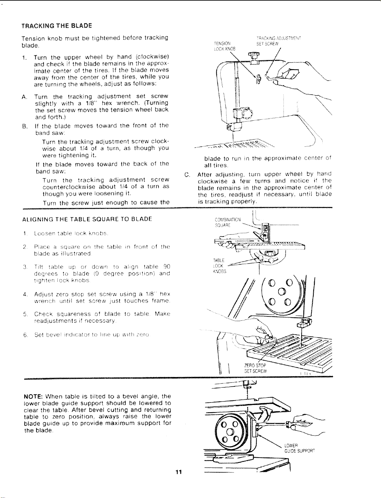
TRACKING THE BLADE
Tension knob must be t ghtened before tracking
b{ade,
!.
A,
B•
Turn the upper wheel by hand (clockwise)
and check if the btade remains in the approx-
imate center of the tires. If the blade moves
away from the center of the tires, while you
are turning the wheels, adjust as follows:
Turn the tracking adjustment set screw
sNght!y with a !18" hex wrench (Turning
the set screw moves the tension wheel back
and forthj
if the blade moves toward the front of the
band saw:
Turn the tracking adjustment screw ctocM
wise about 114 of a turn, as though you
were tightening it.
If the blade moves toward the back of the
band saw:
Turn the tracking adjustment screw
counterclockwise about 114 of a turn as
though you were !oosening it.
Turn the screw just enough to cause the
T(:';SOft
"_' _ KNOB
_,u\,
5Er SCRF;'-,
"?
C,
blade to ru,'_ in the approximale center of
all tires.
After adjusting, turn upper wheel by b,and
clockwise a few turns and notice if the
blade remains in the approximate center of
the tires• readjust if necessary, until blade
is tracking properly.
ALIGNING THE TABLE SQUARE TO BLADE ......B,_.........._ __.
1 t.oo__ef table ock knob. "<, .._...___.___]__,]-
2 Place a sqcare on the table in fiGht of the . _-: .................
biade as illustrated [_i_ _
3 _'" !
KNOBS
4,
5,
T ¸ ,J
l, table up or down to al_gn table 90
(__jqr_;e,_ to b}ade iO degree position) and
. g] _; lock k "_'"
, > €,t
Adlu.>, zero stop set screw using a 1i8 > hex
wrenct_ tJntU set screw just iouches frame.
Check squareness of blade to table Make
readiustments if necessary
6 Set bev(_,i r:dd;ator to !_r;e up .,.qt_ Zero
!
©
ZERO STOP
NOTE: When table is tilted to a bevel angle, the
lower blade guide support should be lowered to
clear the table. After bevel cutting and returning
table to zero position, always raise the lower
blade guide up to provide maximum support for
the blade.
©
LOWER
GUDr- SUPPORT
11
Loading ...
Loading ...
Loading ...