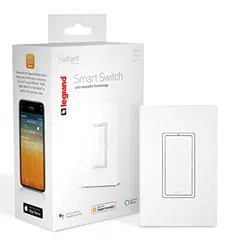
Smart Switch, Wi-Fi
before you start
Review this guide in its entirety. Consult an electrician with any questions or if
you are unsure of your abilities.
Warning: Incorrect installation could result in death, serious injury, and/or
damage to your home or devices.
Caution: To reduce the risk of injury and/or overheating and damage to
other equipment:
• For dry, indoor use only.
• Do not use to power medical
equipment.
• Not suitable as a disconnecting
means.
• Do not use with loads exceeding the
device load rating (see page 16).
what you need
REQUIRED:
Phillips-head screwdriver
Flat blade screwdriver
• Connect the smart switch to a 120
VAC, 60 Hz power source ONLY.
• Always use copper wire to install
the smart switch and follow all
applicable local and national
electrical codes.
Visit www.legrand.us/radiant/smart-lighting/support for support.
YOU MAY ALSO NEED:
Voltage tester, pliers, wire cutter, wire
stripper, electrical tape, fl ashlight, wiring
leads (included), and wire nuts (included)
installation & setup
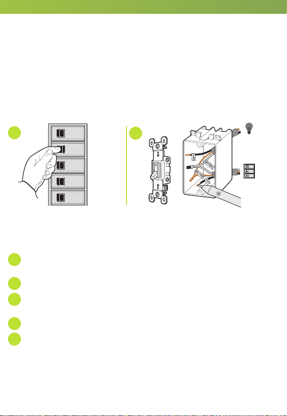
1 | turn off power to device at circuit breaker
Flip existing light switch multiple times to confi rm power is off.
NOTE: Ensure power is off to all devices in electrical box.
OFF
ON
OFF
ON
OFF
ON
OFF
ON
OFF
ON
2 | remove existing device
Check for the following wires:
a
HOT or LINE: Receives power from the circuit box. Referred to as “hot” for
the purposes of this guide. Do not touch or let “hot” wires contact other wires.
b
LOAD: Directs power to your light(s).
c
NEUTRAL: Creates a path to return current to the power source when the
device is off. Required for your switch installation.
d
GROUND: Provides a safe path for electricity in the event of a short circuit.
e
TRAVELER: If more than one switch controls the light, an additional wire
will be in the box that “travels” to the other switch.
OFF
ON
OFF
ON
OFF
ON
VOLTAGE
TESTER
Load
Supply
“Hot”
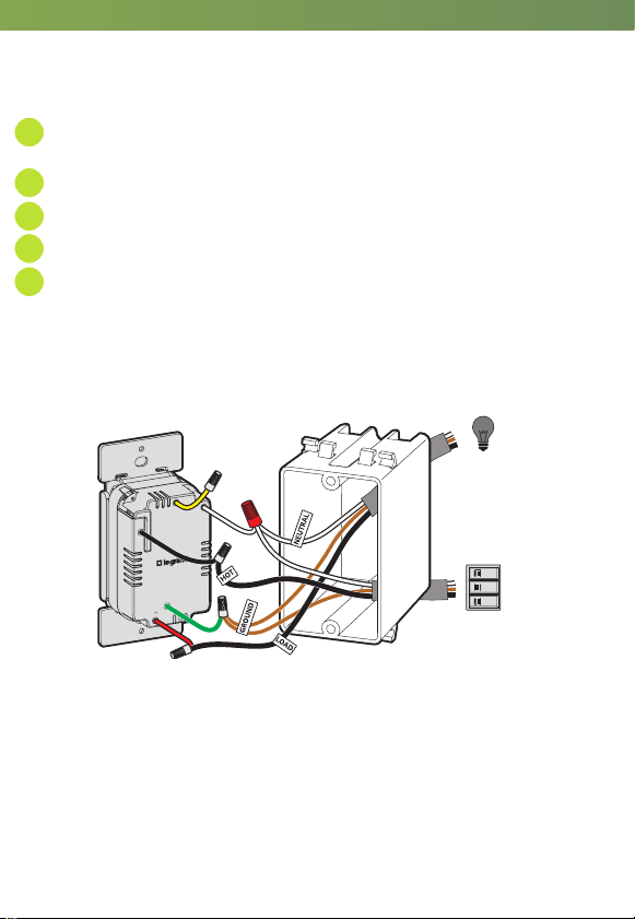
3a | wire smart switch
Use the wire nuts provided to secure the wires together.
a
Connect the WHITE neutral wire on the switch to the neutral wires in the
box, using the red wire nut.
b
Connect the LOAD wire on the switch to the load wire in the box.
c
Connect the HOT wire on the switch to the hot wire(s) in the box.
d
Connect the GREEN ground wire on the switch to the ground wire(s) in the box.
e
If the light is controlled with only one switch, use a wire nut to cap the
YELLOW traveler wire on the device and proceed to step 4.
If the light is controlled by two or more switches (3-way), see 3b
for instructions.
1-POLE
Ground
WHITE
3-WAY
HOT
OFF
ON
OFF
ON
OFF
ON
Load
Supply
“Hot”
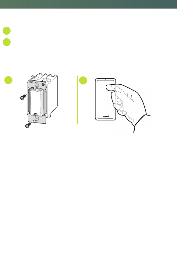
4 | secure smart switch
a
Fold wires into electrical box, taking care not to pinch a wire.
b
Use included screws to secure smart switch to electrical box. Do not fully
tighten the screws.
5 | test the smart switch
NOTE: See getting to know your switch section for feature details.
Turn the power back on at the circuit breaker and press switch to turn light on/off.
TROUBLESHOOTING TIP:
If the device is not powering check wiring to determine if you have reversed the
“HOT” and “LOAD” wiring.
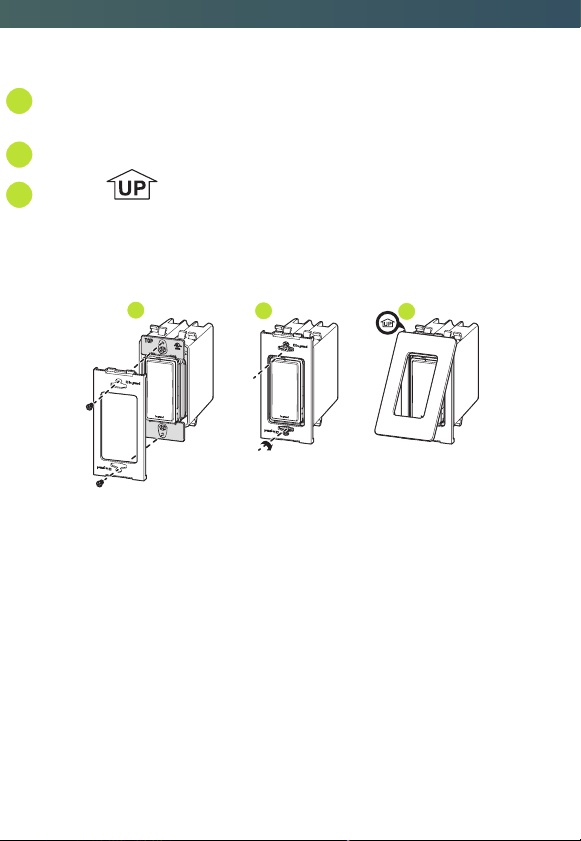
6 | attach wall plate
a
Use the sub-plate screws (provided) to secure the sub-plate to the
smart switch.
b
Tighten device screws to secure to the electrical box.
c
Angle the end of the wall plate over the top edge of the sub-plate.
Push the screwless wall plate down and in until it “snaps” into place over
the sub-plate.
NOTE: To remove the wall plate, place the tip of a fl at blade screwdriver into the slot
under the wall plate and twist gently.
THIS SIDE OUT
MOUNT OVER DEVICE
THIS SIDE OUT
MOUNT OVER DEVICE
THIS SIDE OUT
MOUNT OVER DEVICE
1 32
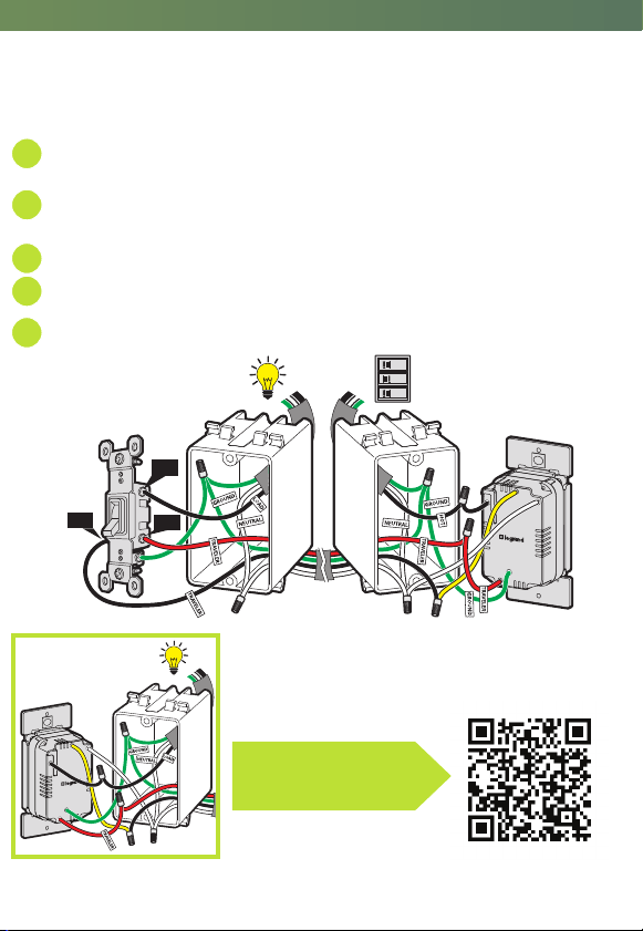
3b (optional) | wire 3-way smart switch
This product will work with existing three-way switches. To wire Smart Switch to
the electrical panel side of the circuit.
a
Connect the WHITE neutral wire on the switch to the neutral wires in the
box, using the red wire nut.
b
Connect the LOAD wire on the switch to one of the two traveler wires (the
wires connected to the gold screws) in the box.
c
Connect the HOT wire on the switch to the hot wire(s) in the box.
d
Connect the GREEN ground wire on the switch to the ground wire(s) in the box.
e
Connect the YELLOW wire to the remaining traveler wire in the box.
1
2
SCAN TO WATCH THE
INSTALLATION VIDEO
SCAN TO SEE HOW TO
WIRE 3-WAY SWITCH
a
b
c
4
5
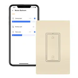
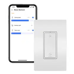
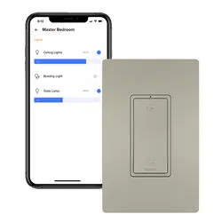
7 | set up your system
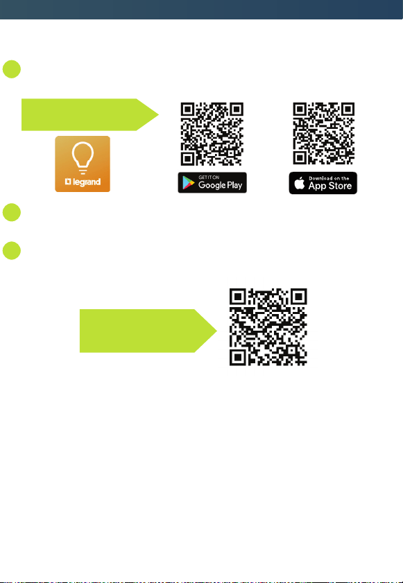
a
Download and launch the Smart Lights, Wi-Fi app by Legrand. The app is
available on the App Store or on Google Play.
b
Connect your smart switch to your home network by following the step by
step instructions in the app.
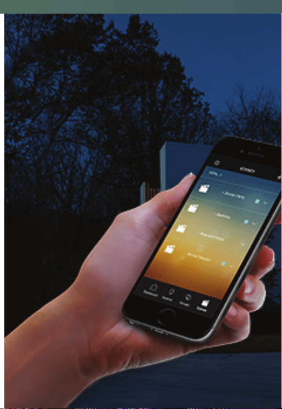
c
Use the app to control your smart switch.
Google Play and the Google Play logo are trademarks of Google LLC.
App Store is a service mark of Apple Inc., registered in the U.S. and other countries.
SCAN TO WATCH HOW
TO SET UP THE APP
SCAN TO DOWNLOAD
HOT
3-WAY
WHITE
1-POLE
Ground
Gold
Screw
Black
Screw
Gold
Screw
OFF
ON
OFF
ON
OFF
ON
Supply
“Hot”
Load
WWRL10
1-POLE
Ground
WHITE
3-WAY
HOT
Black
Screw
Gold
Screw
Gold
Screw
OFF
ON
OFF
ON
OFF
ON
Supply
“Hot”
Load
WWRL10
NOTE: To wire Smart Switch to the load side of the
circuit. Connect the HOT wire on the switch to load
that is being controlled.

Smart Switch, Wi-Fi
before you start
Review this guide in its entirety. Consult an electrician with any questions or if
you are unsure of your abilities.
Warning: Incorrect installation could result in death, serious injury, and/or
damage to your home or devices.
Caution: To reduce the risk of injury and/or overheating and damage to
other equipment:
• For dry, indoor use only.
• Do not use to power medical
equipment.
• Not suitable as a disconnecting
means.
• Do not use with loads exceeding the
device load rating (see page 16).
what you need
REQUIRED:
Phillips-head screwdriver
Flat blade screwdriver
• Connect the smart switch to a 120
VAC, 60 Hz power source ONLY.
• Always use copper wire to install
the smart switch and follow all
applicable local and national
electrical codes.
Visit www.legrand.us/radiant/smart-lighting/support for support.
YOU MAY ALSO NEED:
Voltage tester, pliers, wire cutter, wire
stripper, electrical tape, fl ashlight, wiring
leads (included), and wire nuts (included)
installation & setup
1 | turn off power to device at circuit breaker
Flip existing light switch multiple times to confi rm power is off.
NOTE: Ensure power is off to all devices in electrical box.
OFF
ON
OFF
ON
OFF
ON
OFF
ON
OFF
ON
2 | remove existing device
Check for the following wires:
a
HOT or LINE: Receives power from the circuit box. Referred to as “hot” for
the purposes of this guide. Do not touch or let “hot” wires contact other wires.
b
LOAD: Directs power to your light(s).
c
NEUTRAL: Creates a path to return current to the power source when the
device is off. Required for your switch installation.
d
GROUND: Provides a safe path for electricity in the event of a short circuit.
e
TRAVELER: If more than one switch controls the light, an additional wire
will be in the box that “travels” to the other switch.
OFF
ON
OFF
ON
OFF
ON
VOLTAGE
TESTER
Load
Supply
“Hot”
3a | wire smart switch
Use the wire nuts provided to secure the wires together.
a
Connect the WHITE neutral wire on the switch to the neutral wires in the
box, using the red wire nut.
b
Connect the LOAD wire on the switch to the load wire in the box.
c
Connect the HOT wire on the switch to the hot wire(s) in the box.
d
Connect the GREEN ground wire on the switch to the ground wire(s) in the box.
e
If the light is controlled with only one switch, use a wire nut to cap the
YELLOW traveler wire on the device and proceed to step 4.
If the light is controlled by two or more switches (3-way), see 3b
for instructions.
1-POLE
Ground
WHITE
3-WAY
HOT
OFF
ON
OFF
ON
OFF
ON
Load
Supply
“Hot”
4 | secure smart switch
a
Fold wires into electrical box, taking care not to pinch a wire.
b
Use included screws to secure smart switch to electrical box. Do not fully
tighten the screws.
5 | test the smart switch
NOTE: See getting to know your switch section for feature details.
Turn the power back on at the circuit breaker and press switch to turn light on/off.
TROUBLESHOOTING TIP:
If the device is not powering check wiring to determine if you have reversed the
“HOT” and “LOAD” wiring.
6 | attach wall plate
a
Use the sub-plate screws (provided) to secure the sub-plate to the
smart switch.
b
Tighten device screws to secure to the electrical box.
c
Angle the end of the wall plate over the top edge of the sub-plate.
Push the screwless wall plate down and in until it “snaps” into place over
the sub-plate.
NOTE: To remove the wall plate, place the tip of a fl at blade screwdriver into the slot
under the wall plate and twist gently.
THIS SIDE OUT
MOUNT OVER DEVICE
THIS SIDE OUT
MOUNT OVER DEVICE
THIS SIDE OUT
MOUNT OVER DEVICE
1 32
3b (optional) | wire 3-way smart switch
This product will work with existing three-way switches. To wire Smart Switch to
the electrical panel side of the circuit.
a
Connect the WHITE neutral wire on the switch to the neutral wires in the
box, using the red wire nut.
b
Connect the LOAD wire on the switch to one of the two traveler wires (the
wires connected to the gold screws) in the box.
c
Connect the HOT wire on the switch to the hot wire(s) in the box.
d
Connect the GREEN ground wire on the switch to the ground wire(s) in the box.
e
Connect the YELLOW wire to the remaining traveler wire in the box.
1
2
SCAN TO WATCH THE
INSTALLATION VIDEO
SCAN TO SEE HOW TO
WIRE 3-WAY SWITCH
a
b
c
4
5
7 | set up your system
a
Download and launch the Smart Lights, Wi-Fi app by Legrand. The app is
available on the App Store or on Google Play.
b
Connect your smart switch to your home network by following the step by
step instructions in the app.
c
Use the app to control your smart switch.
Google Play and the Google Play logo are trademarks of Google LLC.
App Store is a service mark of Apple Inc., registered in the U.S. and other countries.
SCAN TO WATCH HOW
TO SET UP THE APP
SCAN TO DOWNLOAD
HOT
3-WAY
WHITE
1-POLE
Ground
Gold
Screw
Black
Screw
Gold
Screw
OFF
ON
OFF
ON
OFF
ON
Supply
“Hot”
Load
WWRL10
1-POLE
Ground
WHITE
3-WAY
HOT
Black
Screw
Gold
Screw
Gold
Screw
OFF
ON
OFF
ON
OFF
ON
Supply
“Hot”
Load
WWRL10
NOTE: To wire Smart Switch to the load side of the
circuit. Connect the HOT wire on the switch to load
that is being controlled.
regulatory information
FCC NOTICE
This device complies with Part 15 of the FCC rules. Operation is subject to the
following two conditions: (1) this device may not cause harmful interference, and
(2) this device must accept any interference received, including interference that
may cause undesirable operation.
This equipment has been tested and found to comply with the limits for a Class
B digital device, pursuant to Part 15 of the FCC Rules. These limits are designed
to provide reasonable protection against harmful interference in a residential
installation. This equipment generates, uses, and can radiate radio frequency
energy and, if not installed and used in accordance with the instructions, may
cause harmful interference to radio communications. However, there is no
guarantee that interference will not occur in a particular installation.
If this equipment does cause harmful interference to radio or television
reception, which can be determined by turning the equipment off and on, the
user is encouraged to try to correct the interference by one or more of the
following measures:
• Reorient or relocate the receiving antenna
• Increase the separation between the equipment and receiver
• Connect the equipment into an outlet on a circuit different from that to
which the receiver is connected
• Consult the dealer or an experienced radio/TV technician for help
This equipment complies with FCC radiation exposure limits set forth for an
uncontrolled environment. This equipment should be installed and operated with
a minimum distance of 20 cm between the transmitter’s radiating structure(s)
and the body of the user or nearby persons.
NOTE: Any changes or modifi cations to this device that are not expressly approved
by the manufacturer will void the warranty and the user’s authority to operate
the equipment.
FCC ID: A3LCWAM210S
IC NOTICE
This device complies with Industry Canada license-exempt RSS standards.
Operation is subject to the following two conditions: (1) this device may not
cause interference; and (2) this device must accept any interference, including
interference that may cause undesired operation of the device.
RF EXPOSURE STATEMENT
This equipment meets the SAR evaluation limits given in RSS-102 Issue 5
requirements at the minimum separation distance of 15 mm to the human body.
Note: Any changes or modifi cations to this device that are not expressly approved
by the manufacturer, will void the warranty and the user’s authority to operate
the equipment.
IC ID: 649E-CWAM210S
warranty
This product is warranted under normal use against defects in workmanship
and materials for as long as you own it. If the product fails due to a
manufacturing defect during normal use, return it for a replacement at the
store where purchased or contact technical support at 1-877-833-3303.
A dated sales receipt must be provided for all replacement requests (legible
copies are acceptable).
Additional warranty details are available at http://www.legrand.us under your
device’s product page.
questions? we're here to help
PHONE: 1-877-833-3303
8:00 a.m. to 8:00 p.m. EST (M-F)
EMAIL: smartlighting@legrand.us
CHAT: https://www.legrand.us/radiant/smart-lighting.aspx
(Click on the
icon to open a dialogue box)
WiFi
®
is a registered trademark of Wi-Fi Alliance
®
.
specifi cations
Load Rating
Resistive 120 VAC, 60 Hz,15 A
Incandescent/halogen 1800 W
Ballast 15 A standard/electronic
Motor ½ HP
Legrand reserves the right to change specifi cations without notice.
Legrand, North America
50 Boyd Avenue
Syracuse, NY 13209
1-877-833-3303
www.legrand.us
©2019 Legrand All Rights Reserved IS3031 07/19
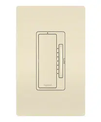
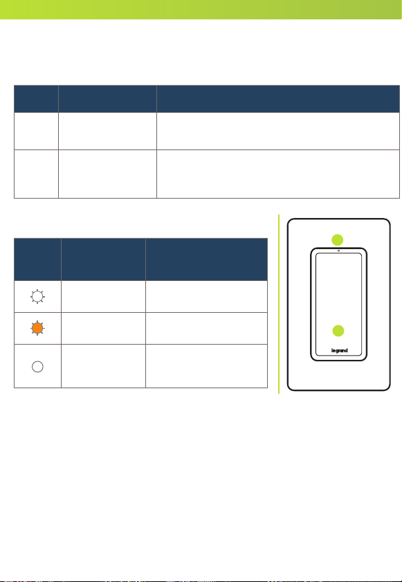
getting to know your switch
Item Name Description
1 Paddle Switch
• Press the top of the paddle to turn the light
on and the bottom to turn the light off.
2 LED Locator Light
• Indicates the current state of the device.
Refer to “LED Locator Light Explanations”
for detail.
LED LOCATOR LIGHT EXPLANATIONS
LED
Color
State of
Light
Explanation
Blinking White Device is updating.
Blinking Amber
Device is ready for
setup on your network.
Solid White
Device is connected to
your network and is
switched off.
2
RESET TO FACTORY DEFAULT
Deleting a device from the app will reset it to factory defaults. To manually
reset the switch to factory defaults press and hold the off button for 10
seconds until you see the LED blink then release. The device will reset in
about 20 seconds after release.
1

regulatory information
FCC NOTICE
This device complies with Part 15 of the FCC rules. Operation is subject to the
following two conditions: (1) this device may not cause harmful interference, and
(2) this device must accept any interference received, including interference that
may cause undesirable operation.
This equipment has been tested and found to comply with the limits for a Class
B digital device, pursuant to Part 15 of the FCC Rules. These limits are designed
to provide reasonable protection against harmful interference in a residential
installation. This equipment generates, uses, and can radiate radio frequency
energy and, if not installed and used in accordance with the instructions, may
cause harmful interference to radio communications. However, there is no
guarantee that interference will not occur in a particular installation.
If this equipment does cause harmful interference to radio or television
reception, which can be determined by turning the equipment off and on, the
user is encouraged to try to correct the interference by one or more of the
following measures:
• Reorient or relocate the receiving antenna
• Increase the separation between the equipment and receiver
• Connect the equipment into an outlet on a circuit different from that to
which the receiver is connected
• Consult the dealer or an experienced radio/TV technician for help
This equipment complies with FCC radiation exposure limits set forth for an
uncontrolled environment. This equipment should be installed and operated with
a minimum distance of 20 cm between the transmitter’s radiating structure(s)
and the body of the user or nearby persons.
NOTE: Any changes or modifi cations to this device that are not expressly approved
by the manufacturer will void the warranty and the user’s authority to operate
the equipment.
FCC ID: A3LCWAM210S
IC NOTICE
This device complies with Industry Canada license-exempt RSS standards.
Operation is subject to the following two conditions: (1) this device may not
cause interference; and (2) this device must accept any interference, including
interference that may cause undesired operation of the device.
RF EXPOSURE STATEMENT
This equipment meets the SAR evaluation limits given in RSS-102 Issue 5
requirements at the minimum separation distance of 15 mm to the human body.
Note: Any changes or modifi cations to this device that are not expressly approved
by the manufacturer, will void the warranty and the user’s authority to operate
the equipment.
IC ID: 649E-CWAM210S
warranty
This product is warranted under normal use against defects in workmanship
and materials for as long as you own it. If the product fails due to a
manufacturing defect during normal use, return it for a replacement at the
store where purchased or contact technical support at 1-877-833-3303.
A dated sales receipt must be provided for all replacement requests (legible
copies are acceptable).
Additional warranty details are available at http://www.legrand.us under your
device’s product page.
questions? we're here to help
PHONE: 1-877-833-3303
8:00 a.m. to 8:00 p.m. EST (M-F)
EMAIL: smartlighting@legrand.us
CHAT: https://www.legrand.us/radiant/smart-lighting.aspx
(Click on the
icon to open a dialogue box)
WiFi
®
is a registered trademark of Wi-Fi Alliance
®
.
specifi cations
Load Rating
Resistive 120 VAC, 60 Hz,15 A
Incandescent/halogen 1800 W
Ballast 15 A standard/electronic
Motor ½ HP
Legrand reserves the right to change specifi cations without notice.
Legrand, North America
50 Boyd Avenue
Syracuse, NY 13209
1-877-833-3303
www.legrand.us
©2019 Legrand All Rights Reserved IS3031 07/19
getting to know your switch
Item Name Description
1 Paddle Switch
• Press the top of the paddle to turn the light
on and the bottom to turn the light off.
2 LED Locator Light
• Indicates the current state of the device.
Refer to “LED Locator Light Explanations”
for detail.
LED LOCATOR LIGHT EXPLANATIONS
LED
Color
State of
Light
Explanation
Blinking White Device is updating.
Blinking Amber
Device is ready for
setup on your network.
Solid White
Device is connected to
your network and is
switched off.
2
RESET TO FACTORY DEFAULT
Deleting a device from the app will reset it to factory defaults. To manually
reset the switch to factory defaults press and hold the off button for 10
seconds until you see the LED blink then release. The device will reset in
about 20 seconds after release.
1

regulatory information
FCC NOTICE
This device complies with Part 15 of the FCC rules. Operation is subject to the
following two conditions: (1) this device may not cause harmful interference, and
(2) this device must accept any interference received, including interference that
may cause undesirable operation.
This equipment has been tested and found to comply with the limits for a Class
B digital device, pursuant to Part 15 of the FCC Rules. These limits are designed
to provide reasonable protection against harmful interference in a residential
installation. This equipment generates, uses, and can radiate radio frequency
energy and, if not installed and used in accordance with the instructions, may
cause harmful interference to radio communications. However, there is no
guarantee that interference will not occur in a particular installation.
If this equipment does cause harmful interference to radio or television
reception, which can be determined by turning the equipment off and on, the
user is encouraged to try to correct the interference by one or more of the
following measures:
• Reorient or relocate the receiving antenna
• Increase the separation between the equipment and receiver
• Connect the equipment into an outlet on a circuit different from that to
which the receiver is connected
• Consult the dealer or an experienced radio/TV technician for help
This equipment complies with FCC radiation exposure limits set forth for an
uncontrolled environment. This equipment should be installed and operated with
a minimum distance of 20 cm between the transmitter’s radiating structure(s)
and the body of the user or nearby persons.
NOTE: Any changes or modifi cations to this device that are not expressly approved
by the manufacturer will void the warranty and the user’s authority to operate
the equipment.
FCC ID: A3LCWAM210S
IC NOTICE
This device complies with Industry Canada license-exempt RSS standards.
Operation is subject to the following two conditions: (1) this device may not
cause interference; and (2) this device must accept any interference, including
interference that may cause undesired operation of the device.
RF EXPOSURE STATEMENT
This equipment meets the SAR evaluation limits given in RSS-102 Issue 5
requirements at the minimum separation distance of 15 mm to the human body.
Note: Any changes or modifi cations to this device that are not expressly approved
by the manufacturer, will void the warranty and the user’s authority to operate
the equipment.
IC ID: 649E-CWAM210S
warranty
This product is warranted under normal use against defects in workmanship
and materials for as long as you own it. If the product fails due to a
manufacturing defect during normal use, return it for a replacement at the
store where purchased or contact technical support at 1-877-833-3303.
A dated sales receipt must be provided for all replacement requests (legible
copies are acceptable).
Additional warranty details are available at http://www.legrand.us under your
device’s product page.
questions? we're here to help
PHONE: 1-877-833-3303
8:00 a.m. to 8:00 p.m. EST (M-F)
EMAIL: [email protected]
CHAT: https://www.legrand.us/radiant/smart-lighting.aspx
(Click on the
icon to open a dialogue box)
WiFi
®
is a registered trademark of Wi-Fi Alliance
®
.
specifi cations
Load Rating
Resistive 120 VAC, 60 Hz,15 A
Incandescent/halogen 1800 W
Ballast 15 A standard/electronic
Motor ½ HP
Legrand reserves the right to change specifi cations without notice.
Legrand, North America
50 Boyd Avenue
Syracuse, NY 13209
1-877-833-3303
www.legrand.us
©2019 Legrand All Rights Reserved IS3031 07/19
getting to know your switch
Item Name Description
1 Paddle Switch
• Press the top of the paddle to turn the light
on and the bottom to turn the light off.
2 LED Locator Light
• Indicates the current state of the device.
Refer to “LED Locator Light Explanations”
for detail.
LED LOCATOR LIGHT EXPLANATIONS
LED
Color
State of
Light
Explanation
Blinking White Device is updating.
Blinking Amber
Device is ready for
setup on your network.
Solid White
Device is connected to
your network and is
switched off.
2
RESET TO FACTORY DEFAULT
Deleting a device from the app will reset it to factory defaults. To manually
reset the switch to factory defaults press and hold the off button for 10
seconds until you see the LED blink then release. The device will reset in
about 20 seconds after release.
1
regulatory information
FCC NOTICE
This device complies with Part 15 of the FCC rules. Operation is subject to the
following two conditions: (1) this device may not cause harmful interference, and
(2) this device must accept any interference received, including interference that
may cause undesirable operation.
This equipment has been tested and found to comply with the limits for a Class
B digital device, pursuant to Part 15 of the FCC Rules. These limits are designed
to provide reasonable protection against harmful interference in a residential
installation. This equipment generates, uses, and can radiate radio frequency
energy and, if not installed and used in accordance with the instructions, may
cause harmful interference to radio communications. However, there is no
guarantee that interference will not occur in a particular installation.
If this equipment does cause harmful interference to radio or television
reception, which can be determined by turning the equipment off and on, the
user is encouraged to try to correct the interference by one or more of the
following measures:
• Reorient or relocate the receiving antenna
• Increase the separation between the equipment and receiver
• Connect the equipment into an outlet on a circuit different from that to
which the receiver is connected
• Consult the dealer or an experienced radio/TV technician for help
This equipment complies with FCC radiation exposure limits set forth for an
uncontrolled environment. This equipment should be installed and operated with
a minimum distance of 20 cm between the transmitter’s radiating structure(s)
and the body of the user or nearby persons.
NOTE: Any changes or modifi cations to this device that are not expressly approved
by the manufacturer will void the warranty and the user’s authority to operate
the equipment.
FCC ID: A3LCWAM210S
IC NOTICE
This device complies with Industry Canada license-exempt RSS standards.
Operation is subject to the following two conditions: (1) this device may not
cause interference; and (2) this device must accept any interference, including
interference that may cause undesired operation of the device.
RF EXPOSURE STATEMENT
This equipment meets the SAR evaluation limits given in RSS-102 Issue 5
requirements at the minimum separation distance of 15 mm to the human body.
Note: Any changes or modifi cations to this device that are not expressly approved
by the manufacturer, will void the warranty and the user’s authority to operate
the equipment.
IC ID: 649E-CWAM210S
warranty
This product is warranted under normal use against defects in workmanship
and materials for as long as you own it. If the product fails due to a
manufacturing defect during normal use, return it for a replacement at the
store where purchased or contact technical support at 1-877-833-3303.
A dated sales receipt must be provided for all replacement requests (legible
copies are acceptable).
Additional warranty details are available at http://www.legrand.us under your
device’s product page.
questions? we're here to help
PHONE: 1-877-833-3303
8:00 a.m. to 8:00 p.m. EST (M-F)
EMAIL: smartlighting@legrand.us
CHAT: https://www.legrand.us/radiant/smart-lighting.aspx
(Click on the
icon to open a dialogue box)
WiFi
®
is a registered trademark of Wi-Fi Alliance
®
.
specifi cations
Load Rating
Resistive 120 VAC, 60 Hz,15 A
Incandescent/halogen 1800 W
Ballast 15 A standard/electronic
Motor ½ HP
Legrand reserves the right to change specifi cations without notice.
Legrand, North America
50 Boyd Avenue
Syracuse, NY 13209
1-877-833-3303
www.legrand.us
©2019 Legrand All Rights Reserved IS3031 07/19
getting to know your switch
Item Name Description
1 Paddle Switch
• Press the top of the paddle to turn the light
on and the bottom to turn the light off.
2 LED Locator Light
• Indicates the current state of the device.
Refer to “LED Locator Light Explanations”
for detail.
LED LOCATOR LIGHT EXPLANATIONS
LED
Color
State of
Light
Explanation
Blinking White Device is updating.
Blinking Amber
Device is ready for
setup on your network.
Solid White
Device is connected to
your network and is
switched off.
2
RESET TO FACTORY DEFAULT
Deleting a device from the app will reset it to factory defaults. To manually
reset the switch to factory defaults press and hold the off button for 10
seconds until you see the LED blink then release. The device will reset in
about 20 seconds after release.
1

regulatory information
FCC NOTICE
This device complies with Part 15 of the FCC rules. Operation is subject to the
following two conditions: (1) this device may not cause harmful interference, and
(2) this device must accept any interference received, including interference that
may cause undesirable operation.
This equipment has been tested and found to comply with the limits for a Class
B digital device, pursuant to Part 15 of the FCC Rules. These limits are designed
to provide reasonable protection against harmful interference in a residential
installation. This equipment generates, uses, and can radiate radio frequency
energy and, if not installed and used in accordance with the instructions, may
cause harmful interference to radio communications. However, there is no
guarantee that interference will not occur in a particular installation.
If this equipment does cause harmful interference to radio or television
reception, which can be determined by turning the equipment off and on, the
user is encouraged to try to correct the interference by one or more of the
following measures:
• Reorient or relocate the receiving antenna
• Increase the separation between the equipment and receiver
• Connect the equipment into an outlet on a circuit different from that to
which the receiver is connected
• Consult the dealer or an experienced radio/TV technician for help
This equipment complies with FCC radiation exposure limits set forth for an
uncontrolled environment. This equipment should be installed and operated with
a minimum distance of 20 cm between the transmitter’s radiating structure(s)
and the body of the user or nearby persons.
NOTE: Any changes or modifi cations to this device that are not expressly approved
by the manufacturer will void the warranty and the user’s authority to operate
the equipment.
FCC ID: A3LCWAM210S
IC NOTICE
This device complies with Industry Canada license-exempt RSS standards.
Operation is subject to the following two conditions: (1) this device may not
cause interference; and (2) this device must accept any interference, including
interference that may cause undesired operation of the device.
RF EXPOSURE STATEMENT
This equipment meets the SAR evaluation limits given in RSS-102 Issue 5
requirements at the minimum separation distance of 15 mm to the human body.
Note: Any changes or modifi cations to this device that are not expressly approved
by the manufacturer, will void the warranty and the user’s authority to operate
the equipment.
IC ID: 649E-CWAM210S
warranty
This product is warranted under normal use against defects in workmanship
and materials for as long as you own it. If the product fails due to a
manufacturing defect during normal use, return it for a replacement at the
store where purchased or contact technical support at 1-877-833-3303.
A dated sales receipt must be provided for all replacement requests (legible
copies are acceptable).
Additional warranty details are available at http://www.legrand.us under your
device’s product page.
questions? we're here to help
PHONE: 1-877-833-3303
8:00 a.m. to 8:00 p.m. EST (M-F)
EMAIL: smartlighting@legrand.us
CHAT: https://www.legrand.us/radiant/smart-lighting.aspx
(Click on the
icon to open a dialogue box)
WiFi
®
is a registered trademark of Wi-Fi Alliance
®
.
specifi cations
Load Rating
Resistive 120 VAC, 60 Hz,15 A
Incandescent/halogen 1800 W
Ballast 15 A standard/electronic
Motor ½ HP
Legrand reserves the right to change specifi cations without notice.
Legrand, North America
50 Boyd Avenue
Syracuse, NY 13209
1-877-833-3303
www.legrand.us
©2019 Legrand All Rights Reserved IS3031 07/19
getting to know your switch
Item Name Description
1 Paddle Switch
• Press the top of the paddle to turn the light
on and the bottom to turn the light off.
2 LED Locator Light
• Indicates the current state of the device.
Refer to “LED Locator Light Explanations”
for detail.
LED LOCATOR LIGHT EXPLANATIONS
LED
Color
State of
Light
Explanation
Blinking White Device is updating.
Blinking Amber
Device is ready for
setup on your network.
Solid White
Device is connected to
your network and is
switched off.
2
RESET TO FACTORY DEFAULT
Deleting a device from the app will reset it to factory defaults. To manually
reset the switch to factory defaults press and hold the off button for 10
seconds until you see the LED blink then release. The device will reset in
about 20 seconds after release.
1