Loading ...
Loading ...
Loading ...
[iJii [I nn,
ASSEMBLY
n n iii inl
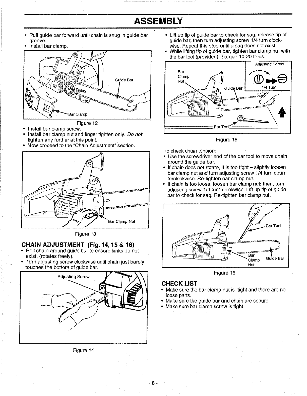
• Pull guide bar forward untir chain is snug in guide bar
groove.
° Install bar clamp.
Guide Bar
Figure 12
• Install bar clamp screw.
• Install bar clamp nut and finger tighten only. Do not
tighten any further at this point.
o Now proceed to the "Chain Adjustment" Section.
• Lift up tip of guide bar to check for sag, release tip of
guide bar, then turn adjusting screw 1/4 turn clock-
wise. Repeat this step until a sag does not exist.
• While lifting tip of guide bar, tighten bar clamp nut with
the bar tool (provided). Torque 10-20 ft-lbs.
Adjusting Screw
Clamp
Guide Bar 1/4 Turn
Figure 15
To check chain tension:
• Use the screwdriver end of the bar tool to move chain
around the guide bar.
• If chain does not rotate, it is tootight- slightly loosen
bar clamp nut and turn adjusting screw 1/4 turn coun-
terclockwise. Re-tighten bar clamp nut.
• Ifchain istoo loose, loosen bar clamp nut; then, turn
adjusting screw I/4 turn clockwise. Lift up tip of guide
bar to check for sag. Re-tighten bar clamp nut.
Bar Clamp Nut
Figure 13
CHAIN ADJUSTMENT (Fig. 14, 15 & 16)
o Roll chain around guide barto ensure kinks do not
exist, (rotates freely),
- Turn adjusting screw clockwise until chain just barely
touches the bottom of guide bar.
Adjusting Screw
Bar Tool
Nut
Figure 16
CHECK LIST
• Make sure the bar clamp nut is tight and there are no
loose parts.
• Make sure the guide bar and chain are secure.
• Make sure bar clamp screw is tight.
Figure 14
-8-
Loading ...
Loading ...
Loading ...