Loading ...
Loading ...
Loading ...
lU i i UlllUlU IInll I I I
CUSTOMER RESPONSIBILITIES
iiiiiiiii i iii i i iiii i i i ii iiiiiiiiiiiiiiiiiiiii
• Place depth gauge tool over each cutter depth gauge.
• File depth gauge with a flat file until it is level with the
top of the depth gauge tool.
= Depth Gauge TOO! /_/
Figure 38
• Maintain rounded front corner of depth gauge with a
flat file. The very top of the depth gauge should be flat
with the front half rounded off with a flat file.
Hook
Angle 25"
_.,=-. Roundec
Corner
Right Way
Too Much squared
Hook Angle _._. Off Corner
oxo
Wrong Way
Figure 39
CHECK GUIDE BAR (Fig. 40 & 41)
A worn guide bar will damage the chain and make cut-
ting difficult. Check the condition of the guide bar each
time the chain issharpened. Conditions include:
• Chain saw cutsto one side or at an angle.
• Chain saw has to be forced through the cut.
° Inadequate supply of oil to the bar and chain.
If replacement is necessary, use only the replacement
reduced kickback guide bar specified for your saw.
Replace the guide bar when:
• the inside groove of the guide bar rail is worn.
• excess heating or burning of the rail is noted.
Correct
Groove
Worn Grooves
FileEdges
Square
• Move stope switch to the "STOP: position.
• Clean all saw dust and any other debris from the guide
bar groove and guide bar oil lubrication.
• Lubricate guide bar nose sprocket after use,
° Burring of bar rails is a normal process of guide bar
rai! wear. Remove these burrs by filing guide bar rail
side edges square with a flat file.
Remove Sawdust
From Guide Bar Groove
Figure 41
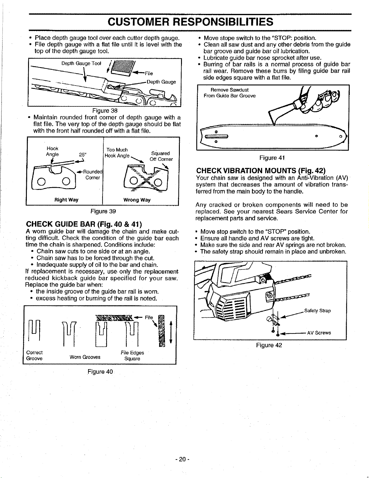
CHECK VIBRATION MOUNTS (Fig. 42)
Your chain saw is designed with an Anti-Vibration (AV)
system that decreases the amount of vibration trans-
ferred from the main body to the handle.
Any cracked or broken components will need to be
replaced. See your nearest Sears Service Center for
replacement parts and service.
• Move stop switch to the "STOP" position,
• Ensure all handle and AV screws are tight.
• Make sure the side and rear AV springs are not broken.
• The safety strap should remain in place and unbroken.
Figure 42
Figure 40
- 20 -
Loading ...
Loading ...
Loading ...