
User's Guide TJ-4005DN/4010TN/TJ-4020TN/4021TN/4021TNR/TJ-4120TN/4121TN/4121TNR
TJ-4005DN/4010TN
TJ-4020TN/4021TN/4021TNR
TJ-4120TN/4121TN/4121TNR
User's Guide (English)
© 2020 Brother Industries, Ltd. All rights reserved.
Version 03
ENG

i
Copyright Information
The copyright in this manual, the software, and firmware in the printer described
therein are owned by Brother. All rights reserved.
Information in this document is subject to change without notice and does not
represent a commitment on the part of the company. No part of this manual may
be reproduced or transmitted in any form or by any means, for any purpose other
than the purchaser’s personal use, without the expressed written permission of
the company.
Trademarks
Wi-Fi
®
is a registered trademark of Wi-Fi Alliance
®
.
CG Triumvirate is a trademark of Agfa Corporation. CG Triumvirate Bold
Condensed font is under license from the Monotype Corporation.
All other trademarks are the property of their respective owners.
Any trade names and product names of companies appearing on Brother
products, related documents and any other materials are all trademarks or
registered trademarks of those respective companies.
Not all models are available in all countries or regions.

ii
Contents
1. Introduction .......................................................................................................... 1
1.1 Product Introduction........................................................................................ 1
1.2 Additional Product Reference ......................................................................... 1
2. Operations Overview ........................................................................................... 2
2.1 Unpack the Label Printer and Check the Components ................................... 2
2.2 Printer Overview ............................................................................................. 3
2.2.1 Front View ................................................................................................ 3
2.2.2 Interior View ............................................................................................. 6
2.2.3 Rear View ................................................................................................ 7
2.3 Control Panels ................................................................................................ 8
2.3.1 LED Indicators and Buttons ..................................................................... 9
2.3.2 Home Screen Icons (Touchscreen Models Only) .................................. 10
2.3.3 Touchscreen Overview .......................................................................... 11
3. Set Up Your Printer ............................................................................................ 16
3.1 Connect the Power Cord .............................................................................. 16
3.2 Load the Ribbon (Not available for TJ-4005DN) ........................................... 17
3.3 Remove Used Ribbon (Not available for TJ-4005DN) .................................. 20
3.4 Load the Media ............................................................................................. 21
3.4.1 Load Label Roll ...................................................................................... 21
3.4.2 Load External Media .............................................................................. 24
3.4.3 Load the Media in Peeler Mode (Optional) ............................................ 27
3.4.4 Load Media in Cutter Mode (Optional) ................................................... 31
4. Improve Print Quality ......................................................................................... 36
4.1 Adjust Print Head Tension to Improve Print Quality ..................................... 36
4.2 Avoid Wrinkled Labels .................................................................................. 36
4.2.1 Adjust Ribbon Tension (Not available for TJ-4005DN) .......................... 36
4.2.2 Change the Print Density/Darkness Settings ......................................... 38
4.2.3 Try Different Media ................................................................................ 38
5. Printing ............................................................................................................... 39
5.1 Printer Driver Installation .............................................................................. 39
5.1.1 USB Connection (Windows/Mac/Linux) ................................................. 39
5.1.2 Wi-Fi Network Connection (Windows) ................................................... 40
5.1.3 Wired Network Connection (Windows) .................................................. 41
5.2 Set the Direct Thermal / Thermal Transfer Print Methods
(Not available for TJ-4005DN) ...................................................................... 42

iii
5.3 Create and Print Labels Using BarTender .................................................... 44
6. Operation ........................................................................................................... 45
6.1 Power-on Utilities .......................................................................................... 45
6.1.1 Gap/Black Mark Sensor Calibration ....................................................... 46
6.1.2 Gap/Black Mark Sensor Calibration, Self-Test,
and Entering Dump Mode ...................................................................... 47
6.1.3 Printer Initialization ................................................................................ 51
6.1.4 Media Sensor Calibration (for the Black Mark Sensor) .......................... 52
6.1.5 Media Sensor Calibration (for the Gap Sensor) ..................................... 52
6.1.6 Skip the AUTO.BAS Program ................................................................ 53
7. Change Printer Settings using the Touchscreen ............................................... 54
7.1 Setting Menu................................................................................................. 54
7.1.1 FBPL Settings ........................................................................................ 54
7.1.2 ZPL2 Settings ........................................................................................ 56
7.2 Sensor Settings ............................................................................................ 59
7.3 Interface Settings .......................................................................................... 60
7.3.1 Serial Communication Settings .............................................................. 60
7.3.2 Ethernet Settings ................................................................................... 61
7.3.3 Wi-Fi Settings ........................................................................................ 62
7.3.4 RFID (Radio Frequency Identification) Settings ..................................... 64
7.4 Advanced Settings ........................................................................................ 70
7.5 File Manager ................................................................................................. 71
7.6 Diagnostic Functions .................................................................................... 72
8. Brother Printer Management Tool (BPM) .......................................................... 73
8.1 Start the BPM ............................................................................................... 73
8.2 Auto-Calibrating the Media Sensor using the BPM ...................................... 74
9. Setting Up the RFID ........................................................................................... 75
9.1 Introduction ................................................................................................... 75
9.2 RFID Calibration ........................................................................................... 76
9.2.1 Load the RFID Media ............................................................................. 76
9.2.2 RFID Calibration Procedure ................................................................... 77
10. Product Specifications ....................................................................................... 80
11. Troubleshooting ................................................................................................. 83
11.1 Common Problems ....................................................................................... 83
11.2 Touchscreen Error Messages ....................................................................... 85
11.3 RFID Error Messages ................................................................................... 86
12. Maintenance ...................................................................................................... 88

1
1. Introduction
1.1 Product Introduction
The robust design of the label printer can handle up to 450 m of ribbon (except TJ-4005DN) and
has the capacity to handle 8" label rolls.
The label printer comes equipped with a number of functions, including:
- Built-in Ethernet
- RS-232C interface
- USB ports (for connecting a keyboard or barcode scanner)
- Wi-Fi Interface Expansion Slot (for the optional Wi-Fi Interface (PA-WI-002))
- 3.5" color Touchscreen (TJ-4021TN/TJ-4021TNR/TJ-4121TN/TJ-4121TNR only)
The label printer uses its high-performance and high-quality built-in Monotype Imaging
®
TrueType font engine with the CG Triumvirate Bold Condensed smooth scalable font. It also
provides a choice of eight different sizes of the alphanumeric bitmap font and supports most of
the standard barcode formats.
1.2 Additional Product Reference
For information on how to write custom programs for your label printer, see the Command
Reference on your model's Manuals page at support.brother.com.

2
2. Operations Overview
2.1 Unpack the Label Printer and Check the Components
Note
Keep the packaging materials in case you must ship the printer.
The components included in the box:
1. Label Printer
a. TJ-4005DN/TJ-4010TN/TJ-4020TN/TJ-4120TN
b. TJ-4021TN/TJ-4121TN
c. TJ-4021TNR/TJ-4121TNR
2. Power Cord
3. USB Cable
4. Paper Core (Not included in TJ-4005DN)
If any components are missing, contact the product manufacturer's customer service or your
local dealer.

3
2.2 Printer Overview
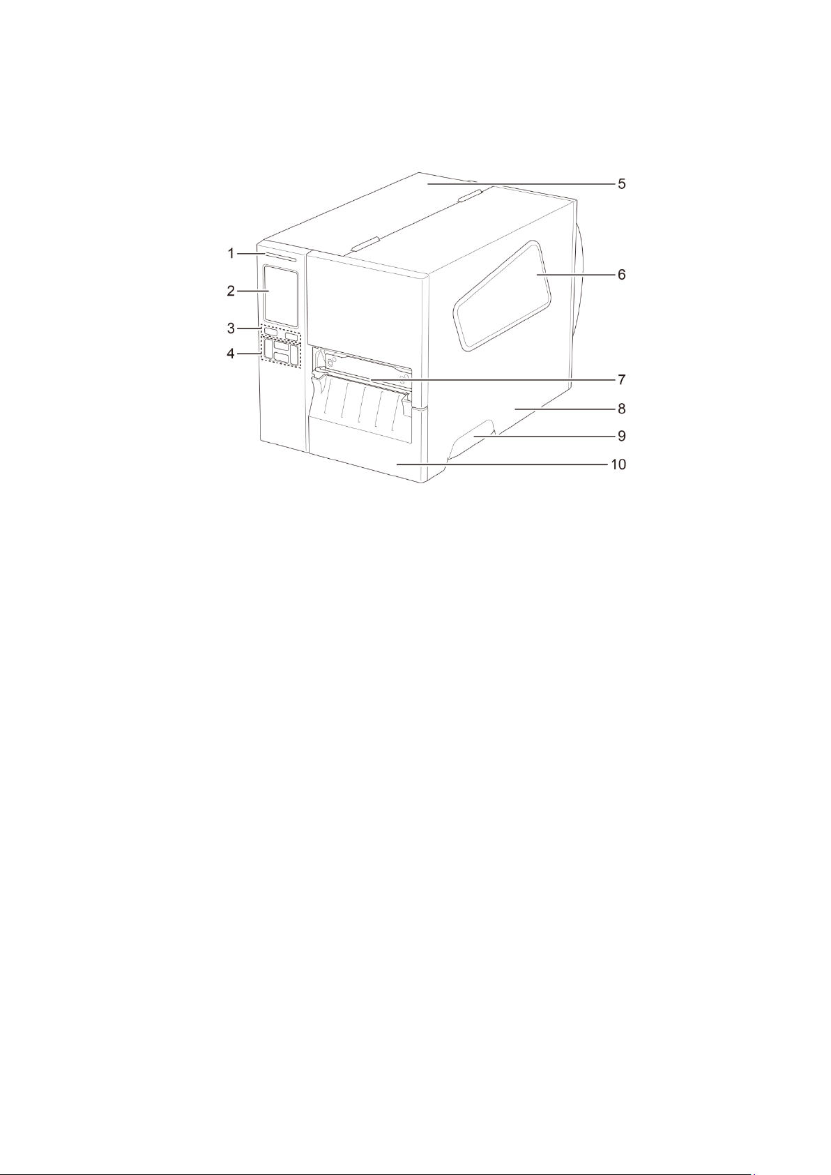
2.2.1 Front View
TJ-4005DN/TJ-4010TN/TJ-4020TN/TJ-4120TN
1. Power LED
2. LED Indicators
3. Pause Button
4. Feed Button
5. PCB Cover
6. Media View Window
7. Media Output Slot
8. Media Cover
9. Media Cover Handle
10. Lower Front Panel
4
TJ-4021TN//TJ-4121TN
1. Power LED
2. Touchscreen
3. Selection Buttons
4. Navigation Buttons
5. PCB Cover
6. Media View Window
7. Media Output Slot
8. Media Cover
9. Media Cover Handle
10. Lower Front Panel

5
TJ-4021TNR/TJ-4121TNR
1. Power LED
2. Touchscreen
3. Selection Buttons
4. Navigation Buttons
5. PCB Cover
6. Media View Window
7. Media Output Slot
8. Media Cover
9. Media Cover Handle
10. RFID Tear Cover
6
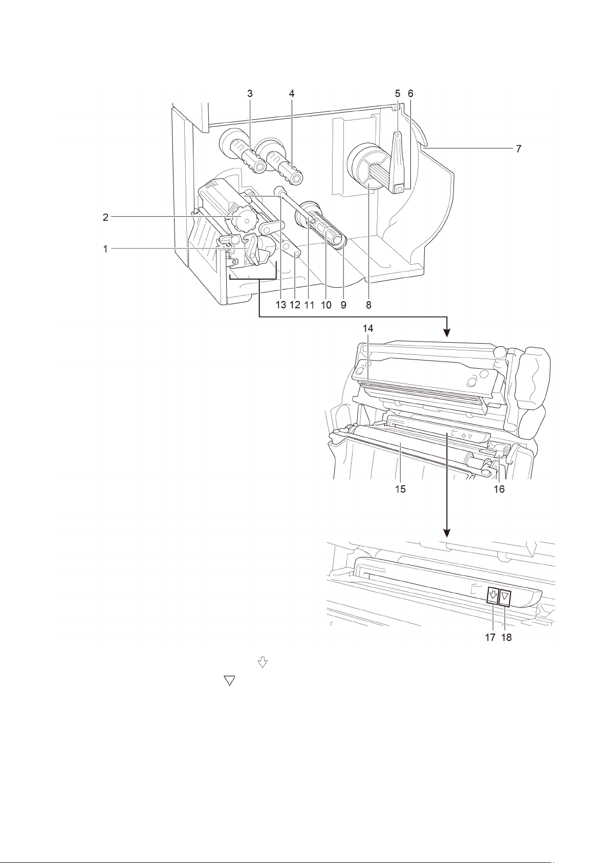
2.2.2 Interior View
1. Print Head Release Lever
2. Print Head Tension Adjustment Knob
3. Ribbon Rewind Spindle**
4. Ribbon Supply Spindle**
5. Label Roll Guard
6. Label Supply Spindle
7. External Label Entry Slot
8. 3" Core Adapter
9. Liner Securing Clip *
10. Liner Rewind Spindle *
11. Media Guide Bar *
12. Damper
13. Ribbon End Sensor
14. Print Head
15. Platen Roller
16. Front Label Guide
17. Black Mark Sensor (shown as )
18. Gap Sensor (shown as )
* Optional accessories for the Label Peeler Assembly.
** TJ-4005DN does not support Thermal Transfer mode with ink ribbon.

7
2.2.3 Rear View
1. External Label Entry Slot
2. Power Switch
3. USB Port (USB 2.0/Hi-Speed Mode)
4. USB Host Port
5. Wi-Fi Interface Expansion Slot *
6. RS-232C Serial Port
7. Ethernet Port
8. Power Cord Socket
* For the optional Wi-Fi Interface (PA-WI-002).
8
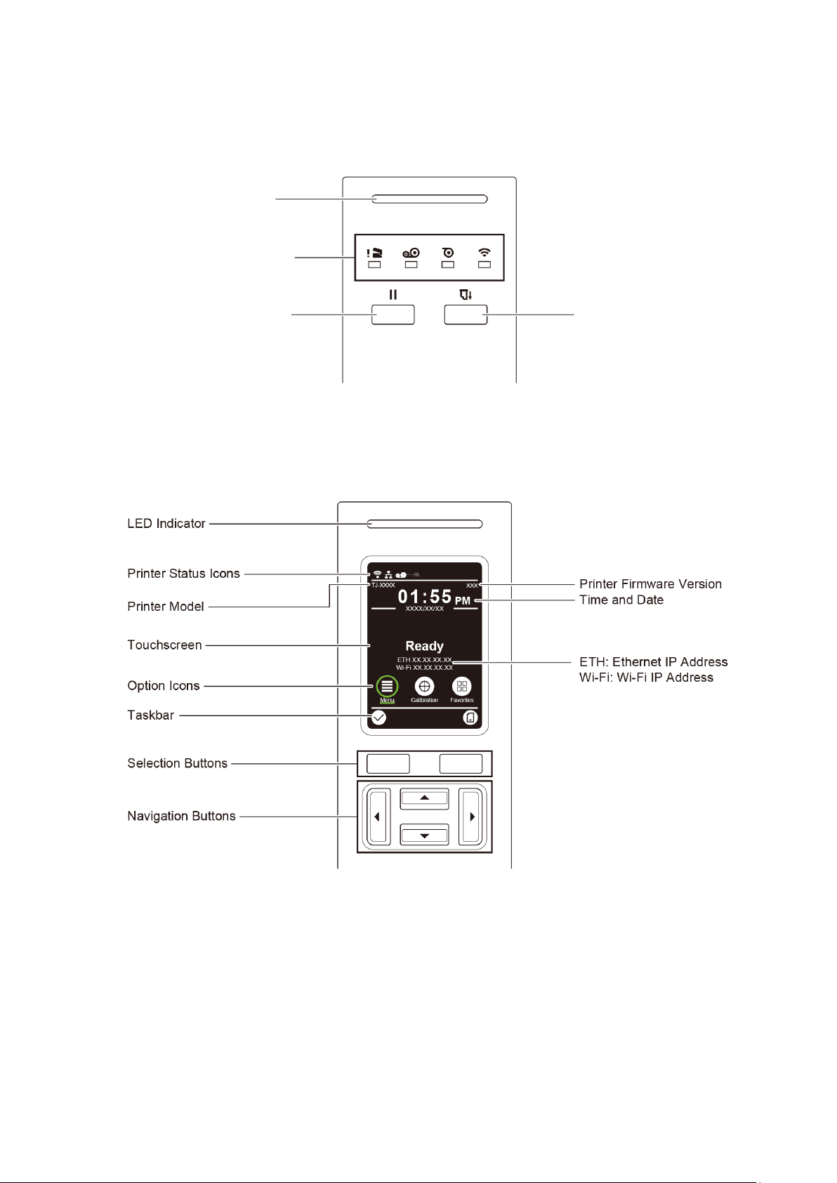
2.3 Control Panels
TJ-4005DN/TJ-4010TN/TJ-4020TN/TJ-4120TN
TJ-4021TN/TJ-4021TNR/TJ-4121TN/TJ-4121TNR
Power LED
LED Indicators
Pause Button
Feed Button
9
2.3.1 LED Indicators and Buttons
Power LED Indications (All Models)
LED Color Description
Green (Lit) The power is on and the printer is ready to use.
Green (Flashing)
- The printer is downloading data from a computer.
- The printer is paused.
Amber The printer is removing data from memory.
Red (Lit) The Print Head is open or there is a Cutter error.
Red (Flashing) There is a printing error, such as “Paper Empty”, “Paper Jam”,
“Ribbon Empty”, or “Memory Error”.
TJ-4005DN
* TJ-4005DN does not support Thermal Transfer mode with ink ribbon.
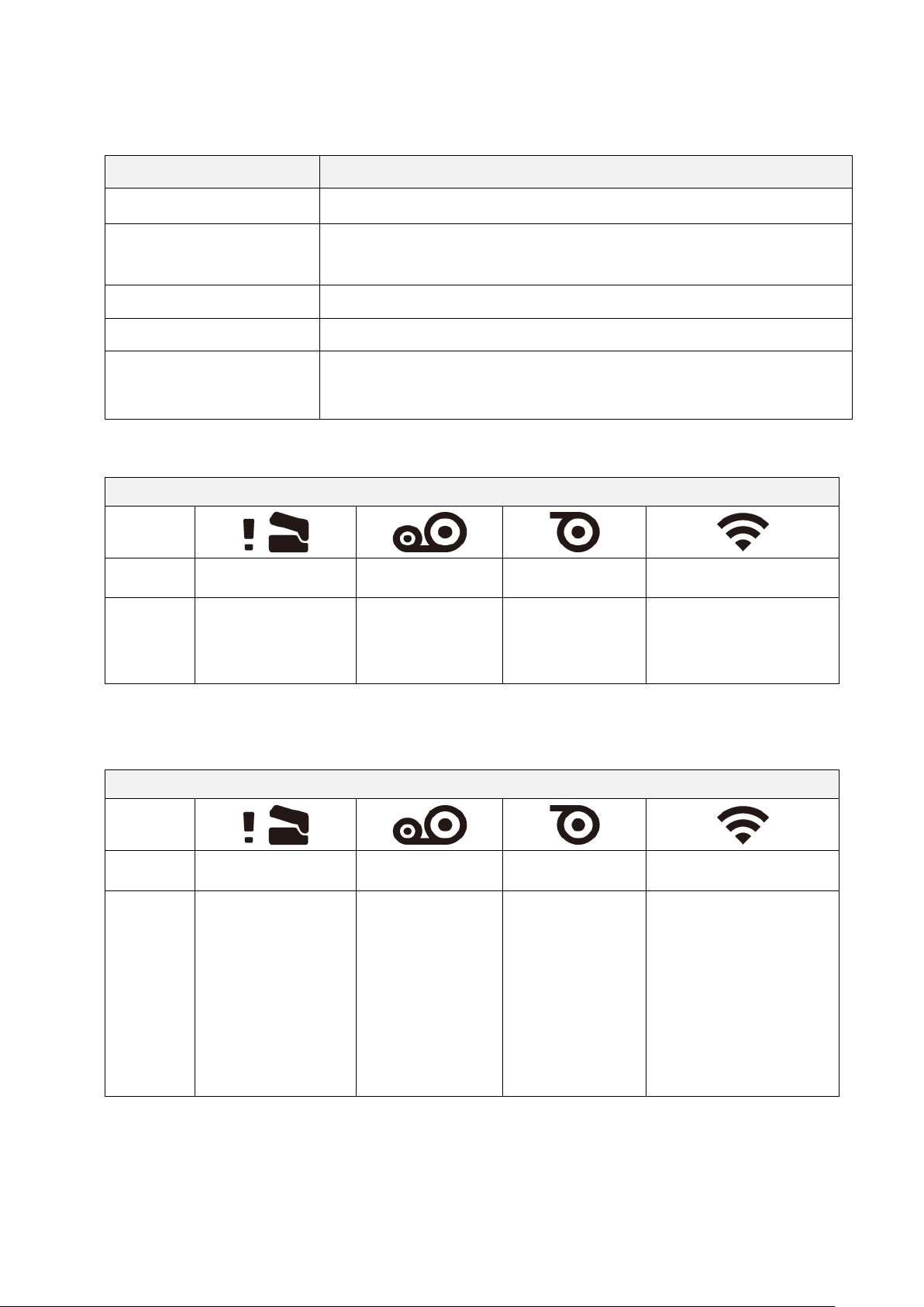
TJ-4010TN/TJ-4020TN/TJ-4120TN
LED Indicators
Icons
Name
Print Head Ribbon Paper Communication
Status
Lit: Print Head open
Lit: Ribbon
installed *
Lit: Out of paper
Blinking: Paper
jam
Lit: Radio-Frequency
connected
Blinking: Radio-
Frequency
communication
LED Indicators
Icons
Name
Print Head Ribbon Paper Communication
Status
Lit: Print Head open
Lit: Out of ribbon
• Blinking (after
powering the
printer on):
Awaiting the
first print job
• Blinking
(between print
jobs): Ribbon
near end
Lit: Out of paper
Blinking: Paper
jam
Lit: Radio-Frequency
connected
Blinking: Radio-
Frequency
communication
10
TJ-4021TN/TJ-4021TNR/TJ-4121TN/TJ-4121TNR
2.3.2 Home Screen Icons (Touchscreen Models Only)
Printer Status Icons
Option Icons
Taskbar Icons
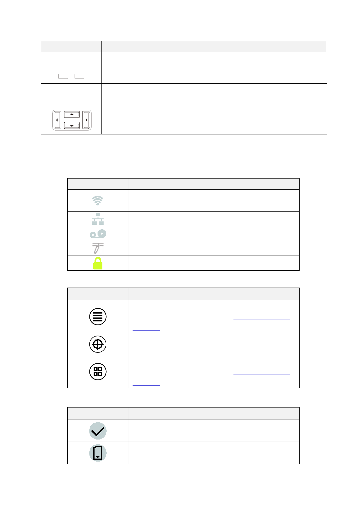
Buttons Function
Selection Buttons
Use to select highlighted icons and menus.
Navigation Buttons
Use to navigate the Touchscreen and highlight icons and menus.
Icon Indication
Wi-Fi device is ready (Available when the Wi-Fi Interface
is installed)
Ethernet is connected
Ribbon capacity (%)
TPH cleaning
Security lock
Icon Function
Access the Main Menu
For more information, see section 2.3.3 Touchscreen
Overview.
Calibrate the media sensor
Enter the “Favorites” screen
For more information, see section 2.3.3 Touchscreen
Overview.
Icon Function
Accept your selection
Feed one label
11
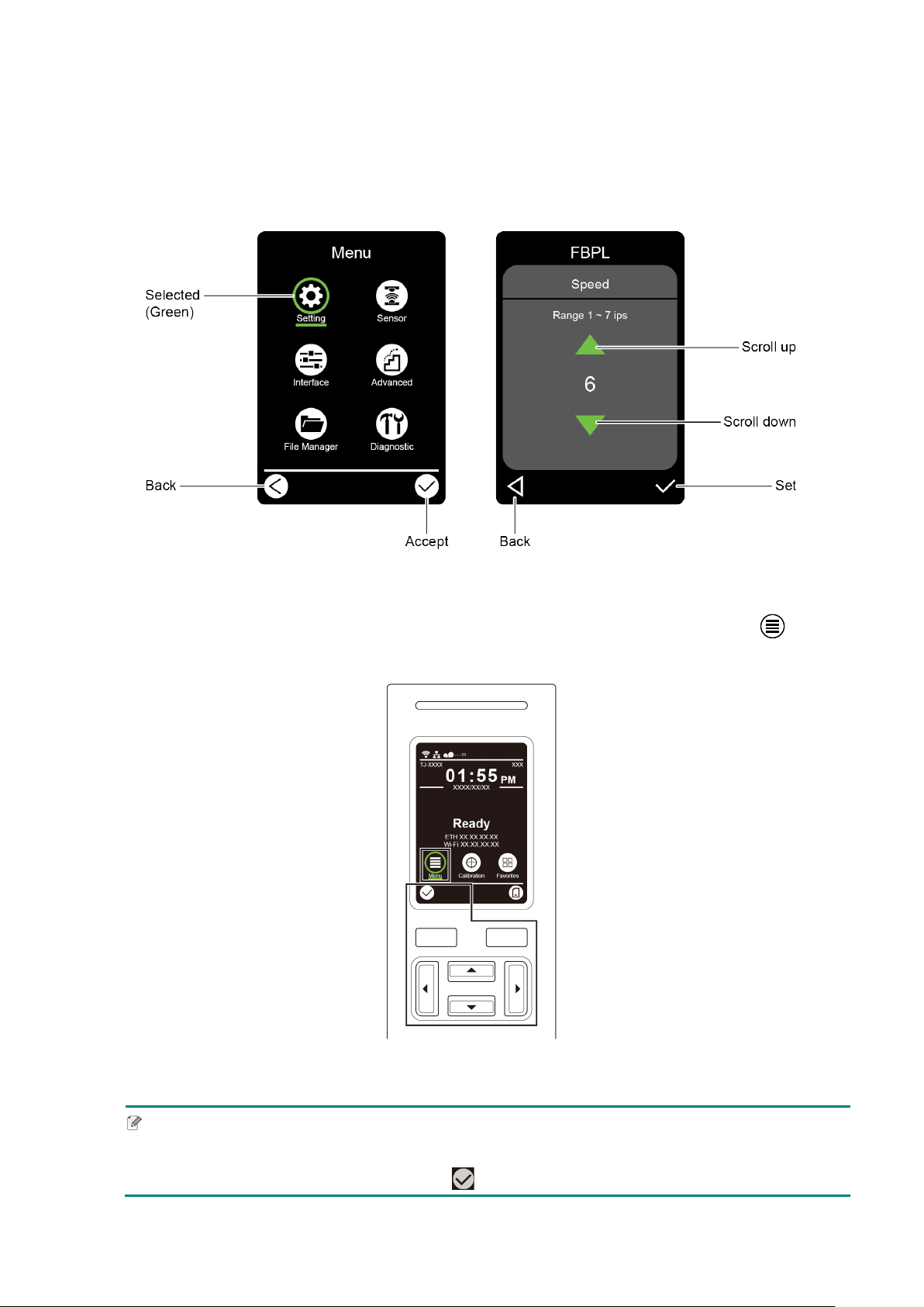
2.3.3 Touchscreen Overview
(Available for TJ-4021TN, TJ-4021TNR, TJ-4121TN and TJ-4121TNR only)
Tap the icons to access printer features and change settings.
Access the Main Menu
Make sure the printer’s Touchscreen displays “Ready”. If not, tap the Menu icon .
Note
You can also use the Control Panel buttons. Use the Navigation buttons to select the Menu icon,
and then press the Selection button under icon.
12
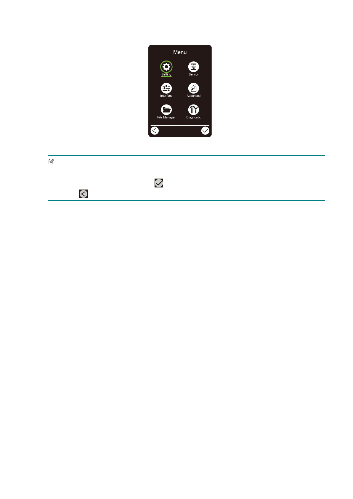
To select an option on the Main Menu, tap the option’s icon.
Note
You can also use the Control Panel buttons. Use the Navigation buttons to browse the options,
and then press the button under the icon. To return to the previous screen, press the button
under the icon.
13
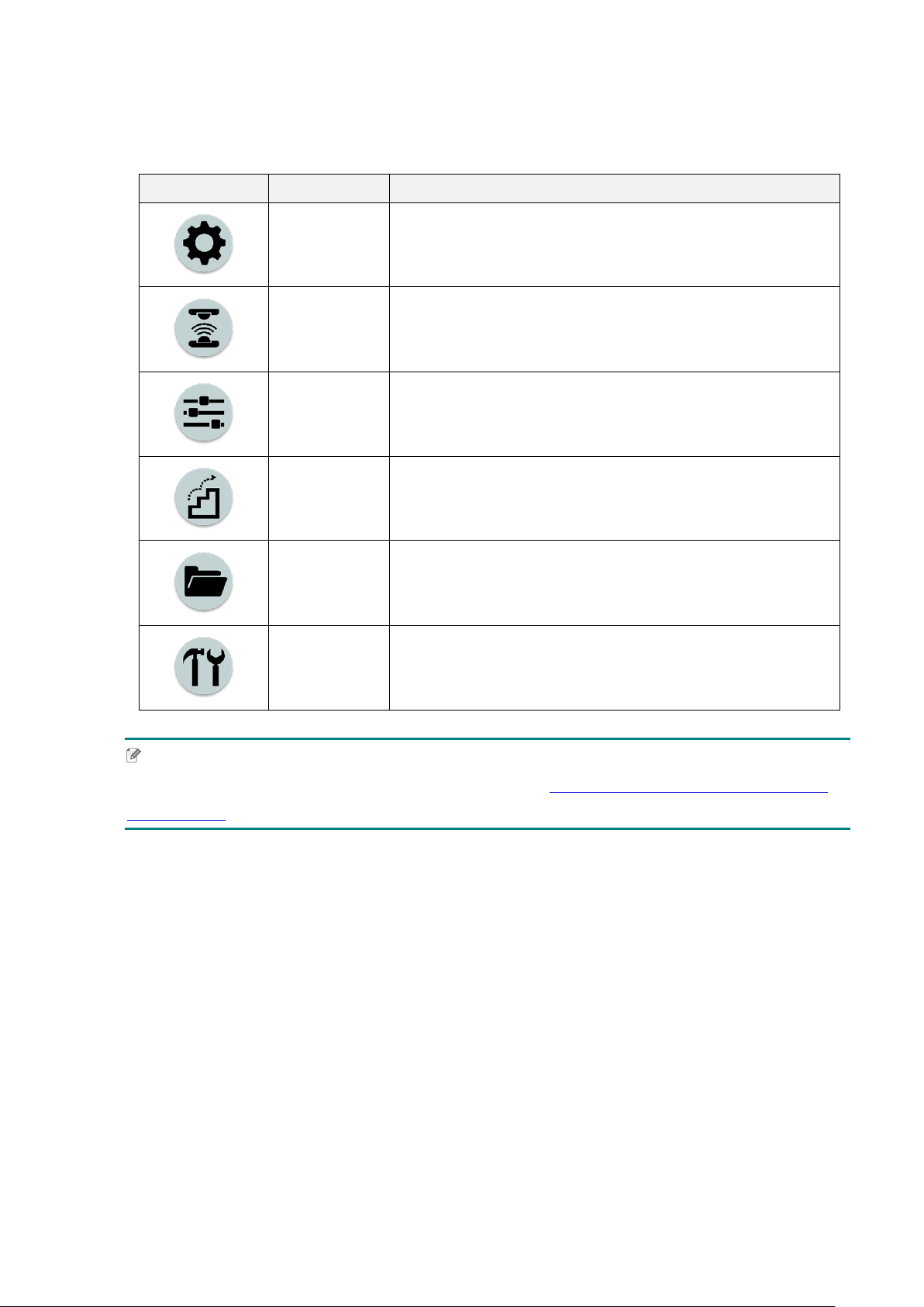
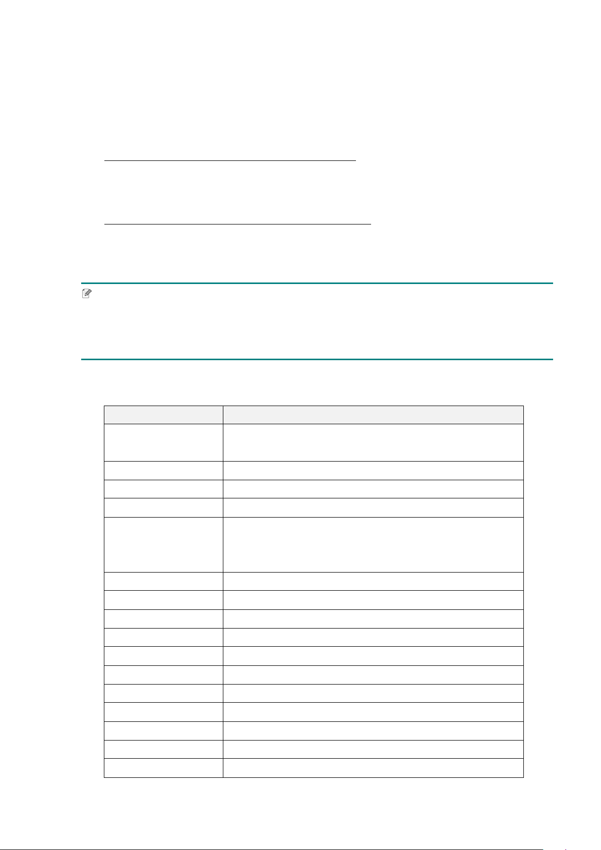
Main Menu Overview
Use the Main Menu options to configure various printer settings without connecting the
printer to a computer.
Icon Option Description
Setting
Configure the printer's FBPL and ZPL2 settings.
Sensor
Calibrate the selected media sensor. We recommend
calibrating the sensor every time you change the media.
Interface
Configure the printer interface settings.
Advanced
Configure the printer's Touchscreen, initialization, cutter
type, or media low warning settings.
File Manager
Check or manage the available printer memory.
Diagnostic
Check the printer status to help troubleshoot any issues.
Note
For more information about printer settings, see section 7. Change Printer Settings using the
Touchscreen.
14
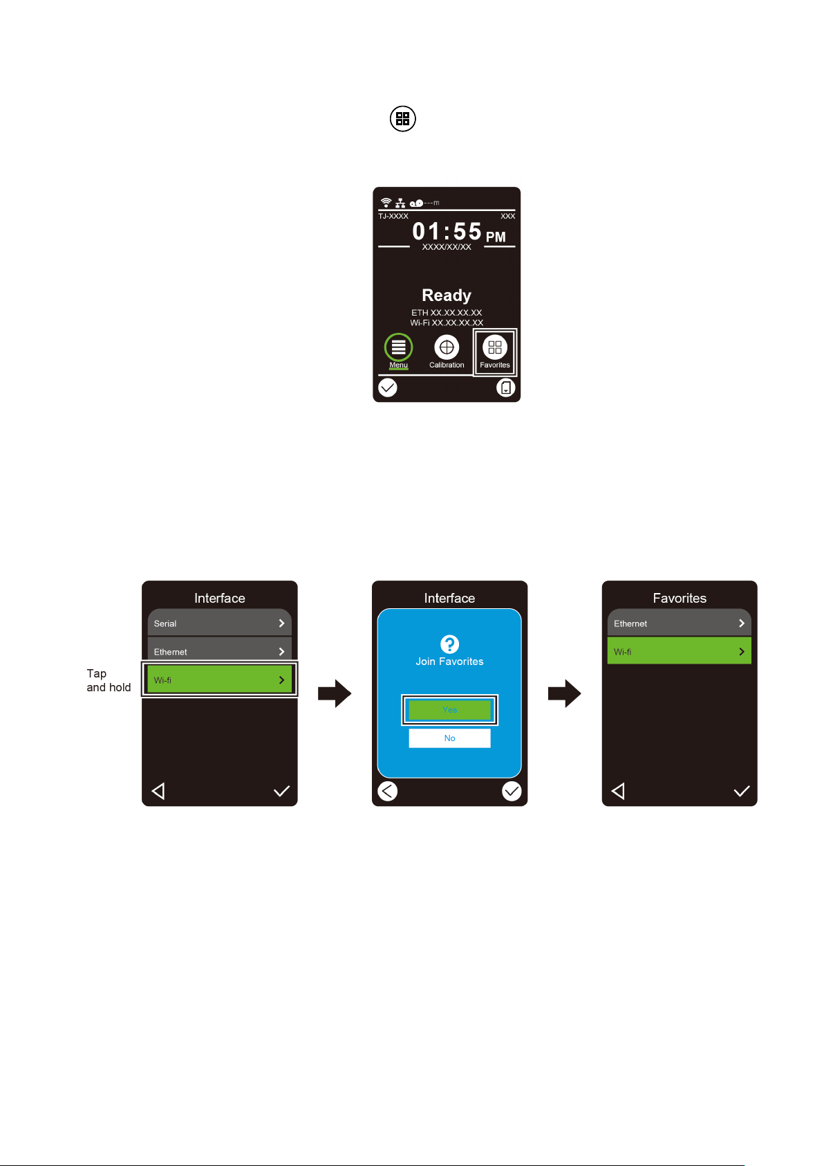
Favorites
Add frequently used Main Menu options to “Favorites” for quick access. To display the
“Favorites” list, tap the Favorites icon .
To add an option to the “Favorites” list:
1. Tap and hold the option you want to add to favorites until “Join Favorites” appears.
2. Tap “Yes”.
15
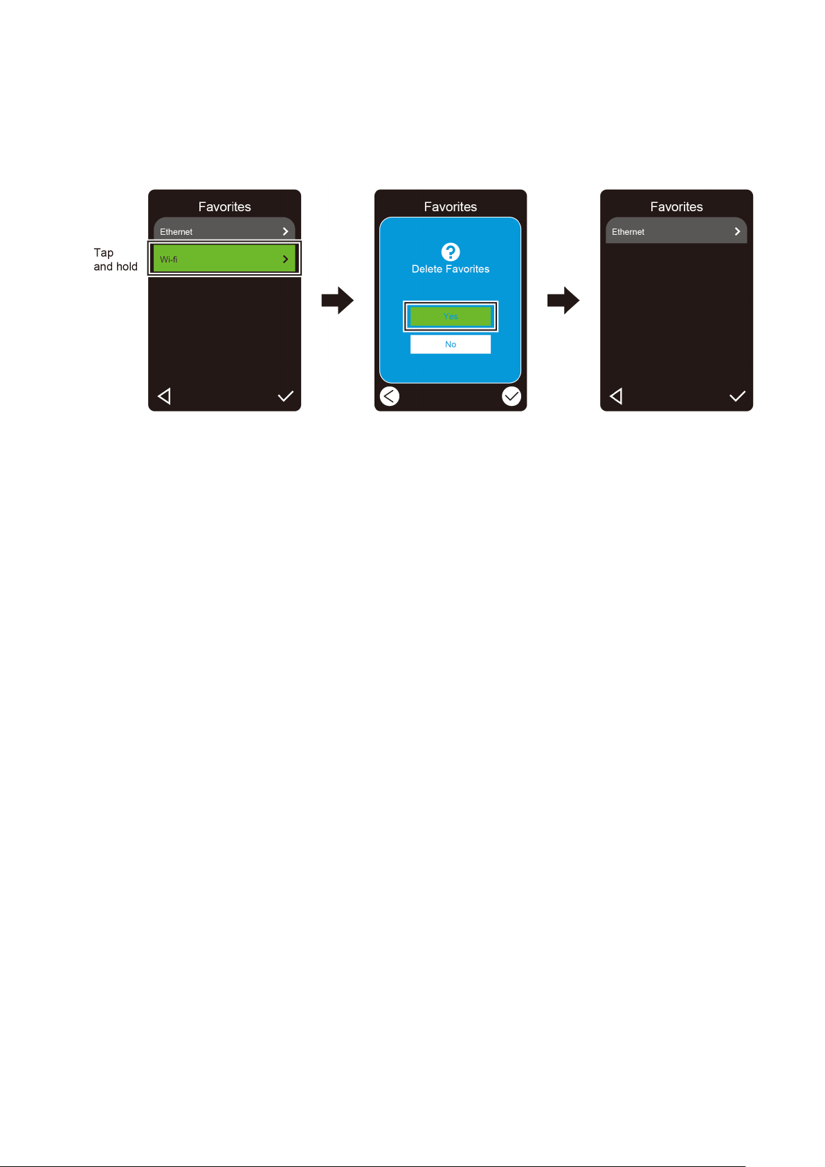
To remove an option from the “Favorites” list:
1. Tap and hold the option you want to remove from favorites until “Delete Favorites”
appears.
2. Tap “Yes”.

16
3. Set Up Your Printer
3.1 Connect the Power Cord
1. Place the printer on a flat, secure surface.
2. Make sure the Power Switch is in the OFF position.
3. Connect the printer to the computer using a USB cable.
4. Plug the Power Cord into the Power Cord Socket at the rear of the printer, and then plug
the Power Cord into a correctly grounded power outlet (earthed electrical socket).
Note
Before plugging the Power Cord into the printer's Power Cord Socket, make sure the
printer's Power Switch is in the OFF position.
After powering the printer on, the LED blinks until the printer receives the first print job.
17
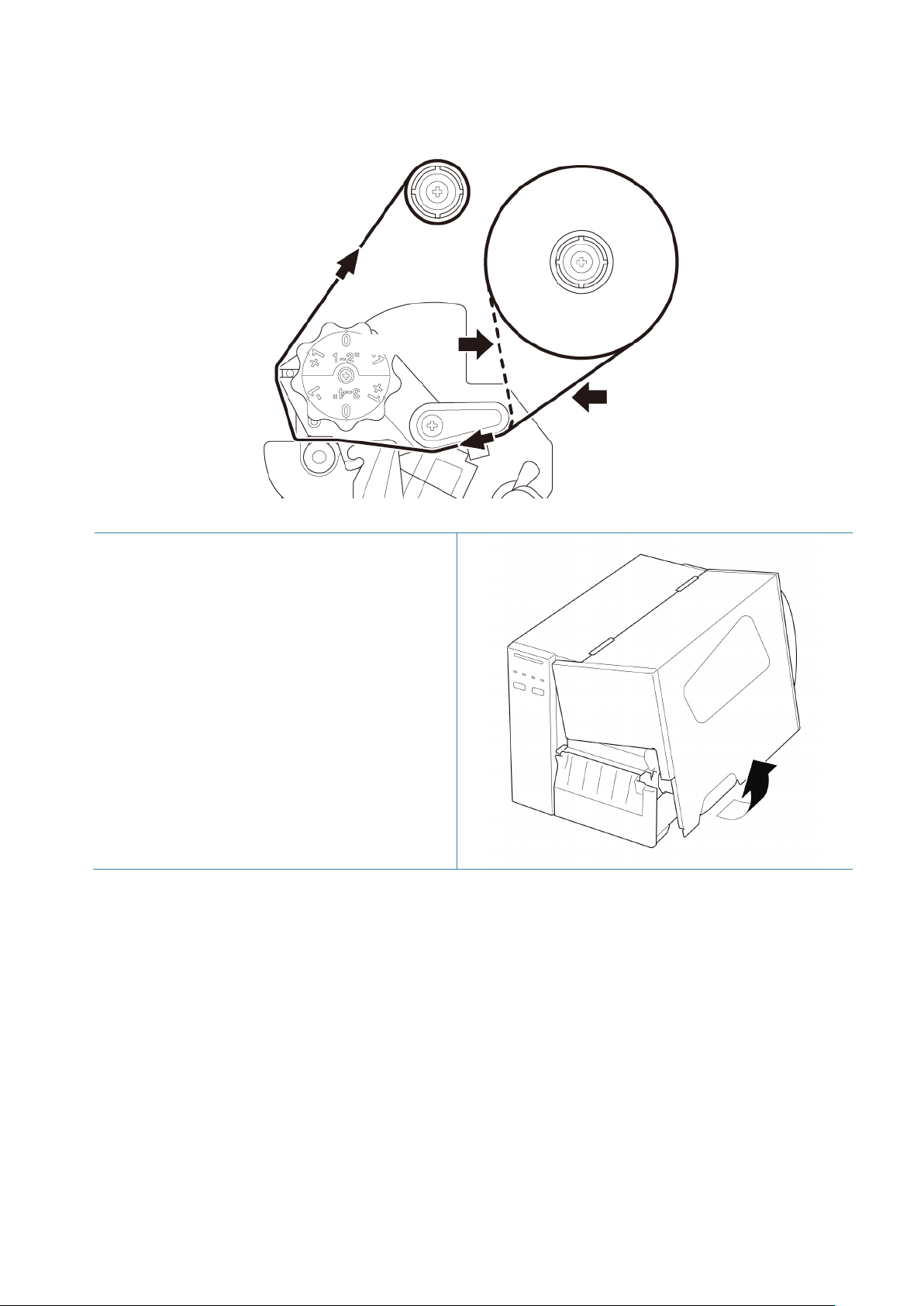
3.2 Load the Ribbon (Not available for TJ-4005DN)
Ribbon loading path
1. Open the Media Cover.
Ink coated outside
Ink coated inside
18
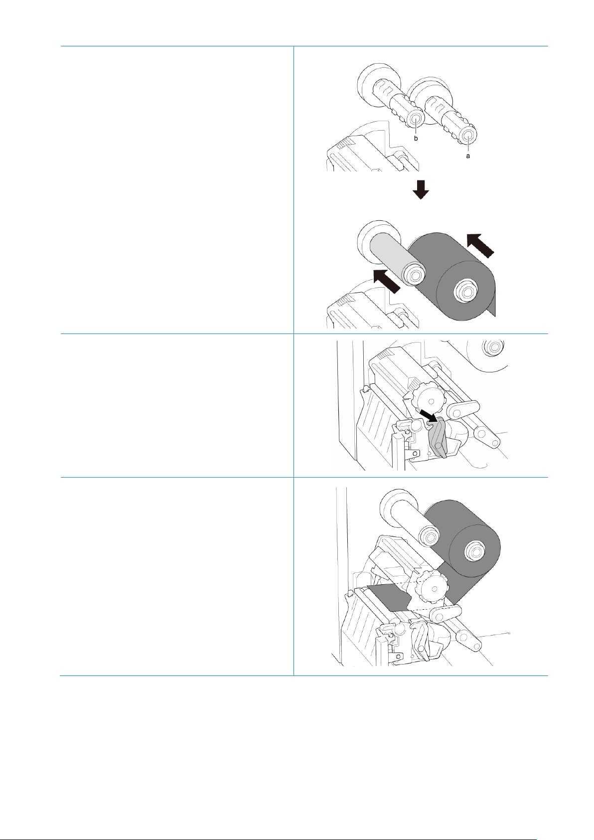
2.
a. Install the ribbon onto the Ribbon
Supply Spindle.
b. Install the Paper Core onto the Ribbon
Rewind Spindle.
3. Push the Print Head Release Lever to
open the Print Head.
4. Thread the ribbon under the ribbon guide
bar and through the ribbon sensor slot
following the loading path printed on the
Label Printer Cover.
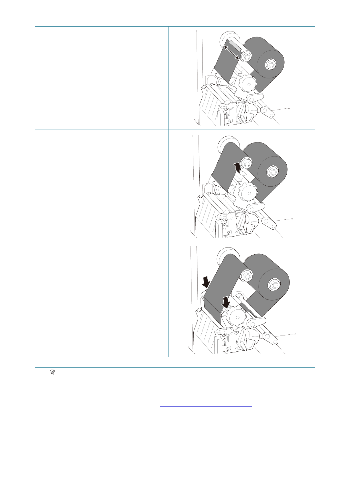
19
5. Adhere the ribbon leader onto the Ribbon
Rewind Paper Core. Keep the ribbon flat
and without wrinkles.
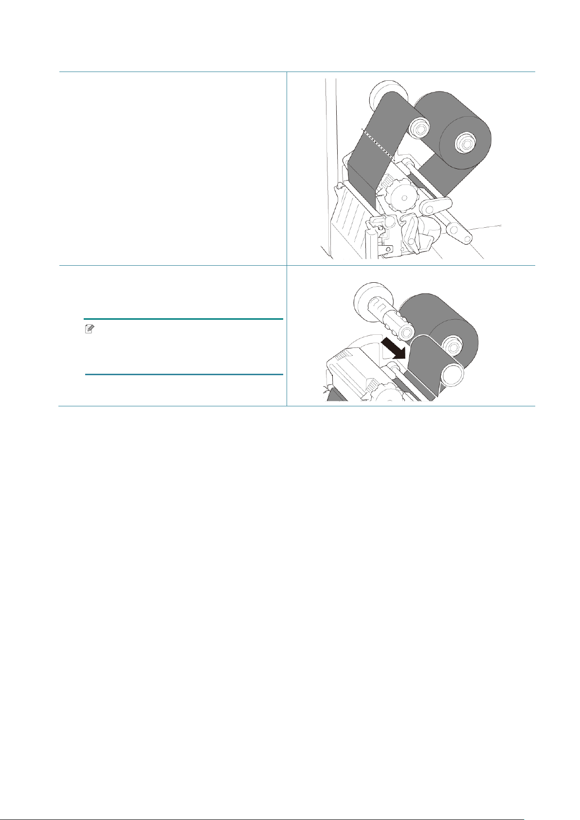
6. Wind the Ribbon Rewind Spindle
counterclockwise about three to five turns
until the ribbon is smooth, flat and without
wrinkles.
7. Close the Print Head by pushing down on
both sides of the Print Head Release
Lever.
Note
TJ-4005DN does not support Thermal Transfer mode with ink ribbon. If the ribbon is
installed onto the ribbon supply spindle, the printer shows the ribbon error status.
For more information, see section 2.3.1 LED Indicators and Buttons.
20
3.3 Remove Used Ribbon (Not available for TJ-4005DN)
1. Cut the used ribbon with scissors along
the dotted line.
2. Remove the ribbon from the Ribbon
Rewind Spindle.
Note
We recommend destroying the used
ribbon if it has retained any visible prints.
21
3.4 Load the Media
3.4.1 Load Label Roll
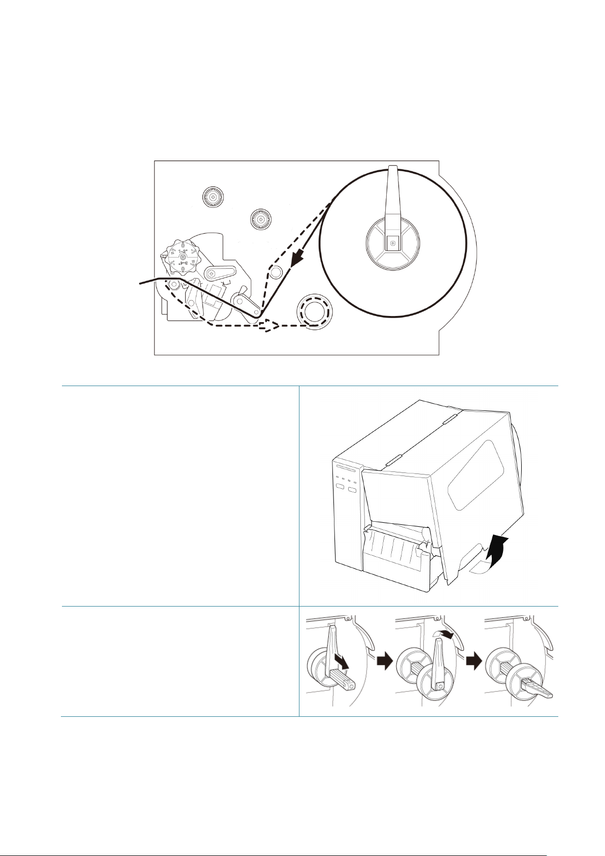
Label Roll loading path
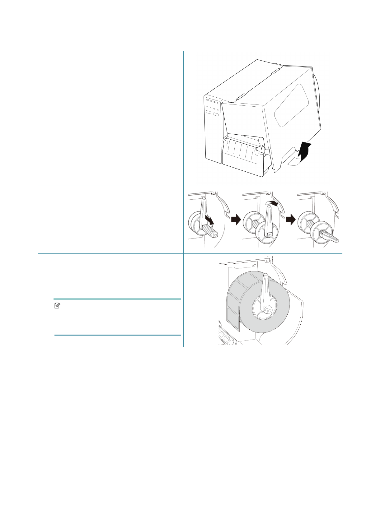
1. Open the Media Cover.
2. Slide the Label Roll Guard horizontally to
the end of the Label Supply Spindle, and
then flip down the Label Roll Guard.
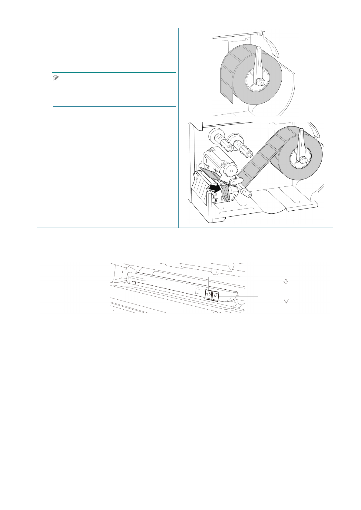
22
3. Place the label roll on the Label Supply
Spindle and then flip the Label Roll Guard
upwards to hold it in place.
Note
Make sure the label print side is facing
up.
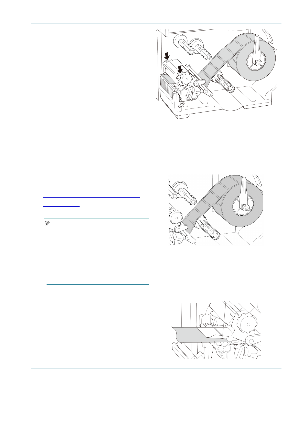
4. Push the Print Head Release Lever and
thread the label through the Damper,
Media Sensor, and Front Label Guide to
install the media.
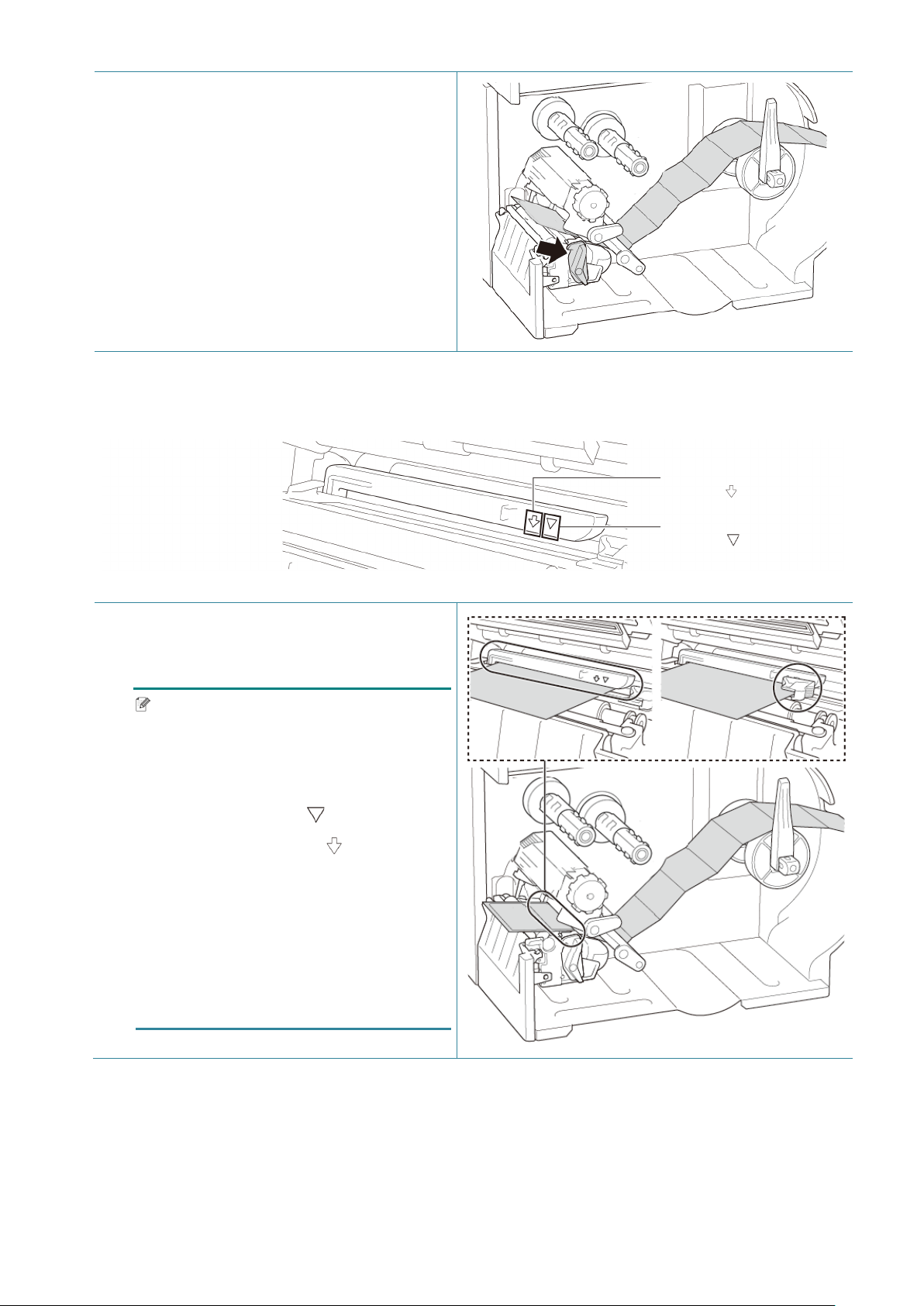
5. Move the Media Sensor by adjusting the Media Sensor Position Adjustment Knob. Make sure
the position of the Gap or Black Mark Sensor matches the position of the Gap/Black Mark on
the label roll.
Black Mark Sensor
(shown as )
Gap Sensor
(shown as )
23
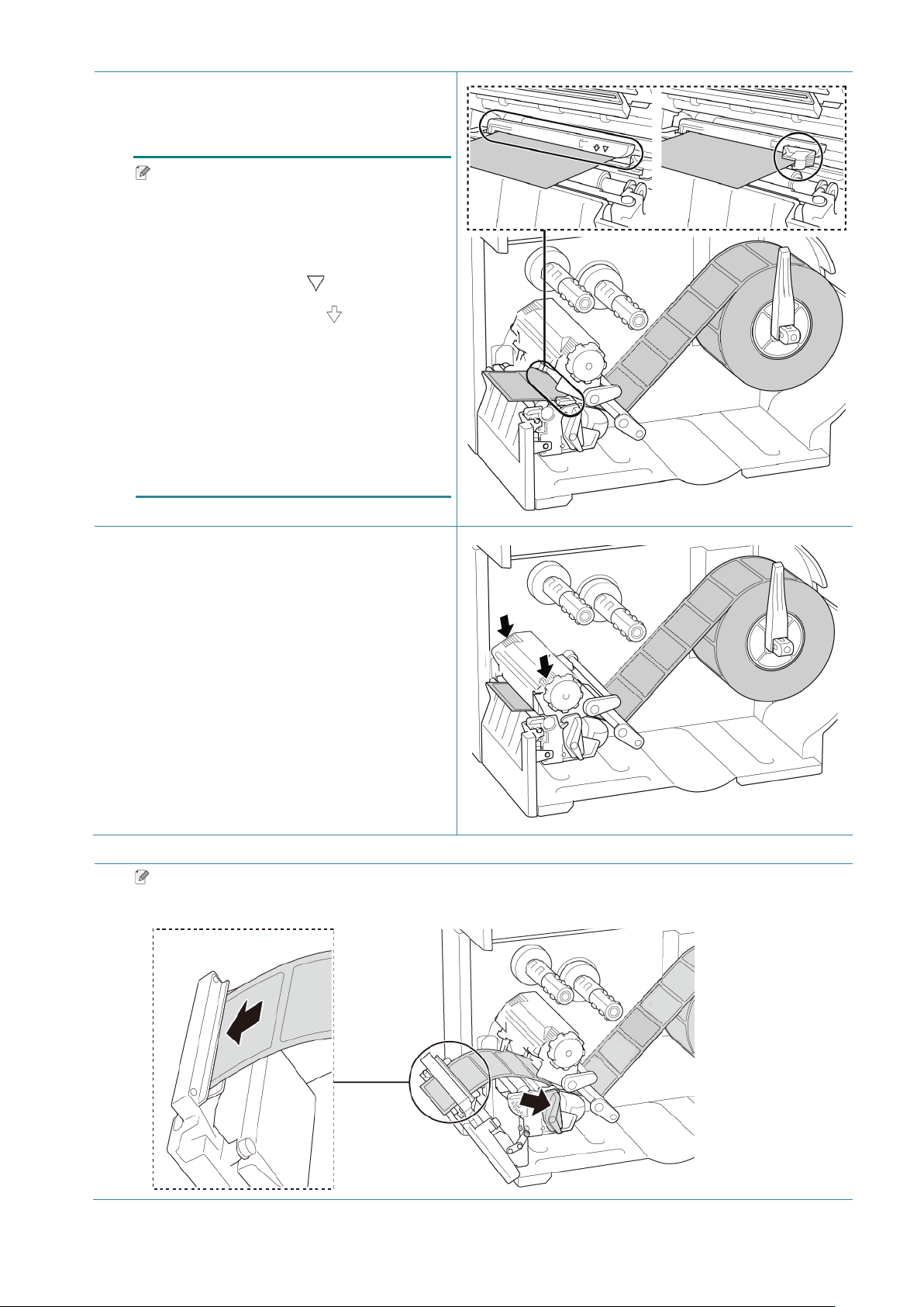
6. Adjust the Front Label Guide to fix the
media position.
Note
• Make sure you thread the media
through the Media Sensor.
• The sensor locations are marked by
the triangle mark (Gap Sensor)
and the arrow mark (Black Mark
Sensor) at the sensor housing.
• The Media Sensor position is
adjustable. Make sure the position of
the Gap or Black Mark Sensor
matches the position of the
Gap/Black Mark on the label roll.
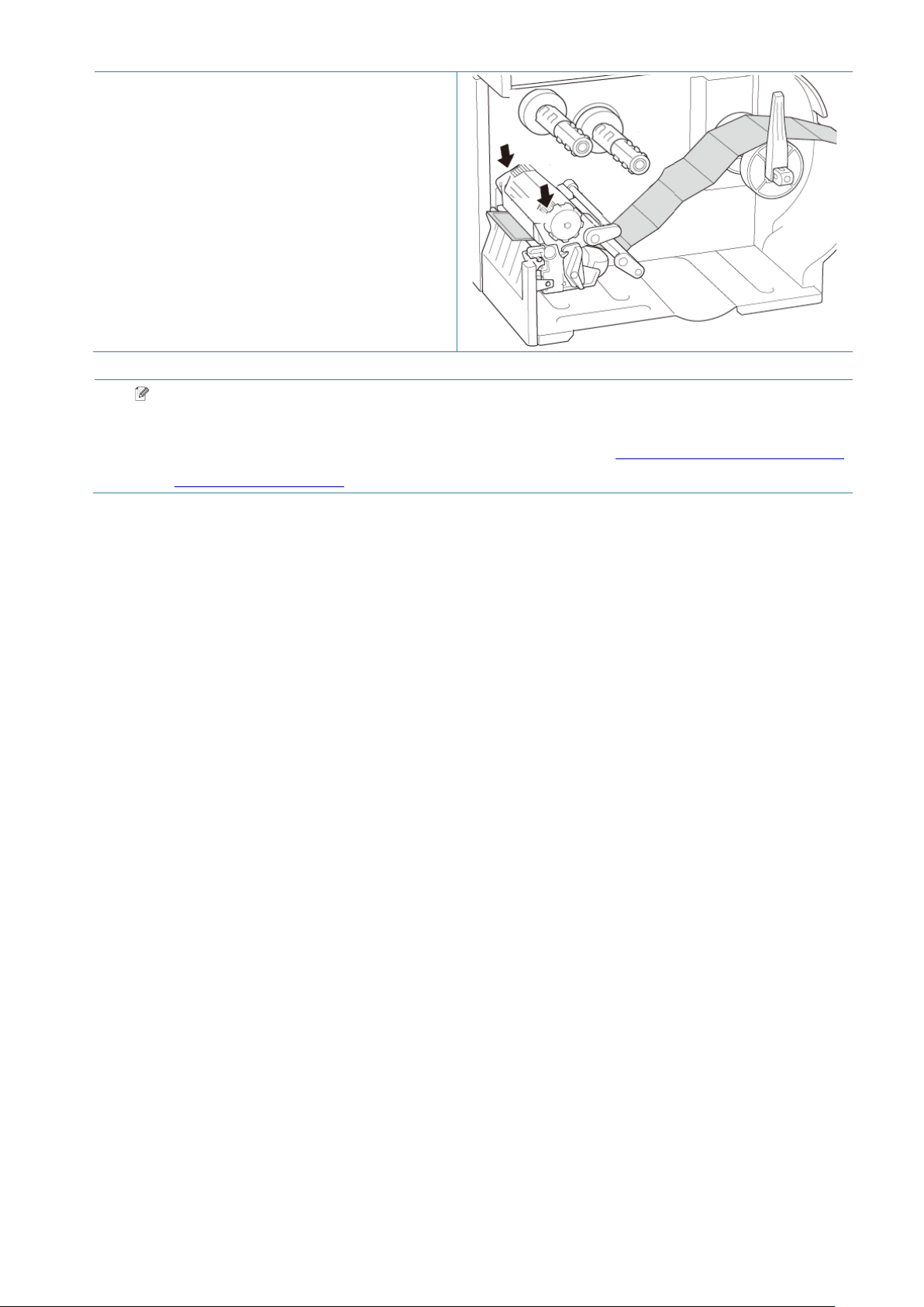
7. Close the Print Head on both sides and
make sure it locks into place.
8. Set the media sensor type and calibrate
the selected sensor.
Note
For RFID models (TJ-4021TNR, TJ-4121TNR), feed the media through the Tear Cover Slot.
24
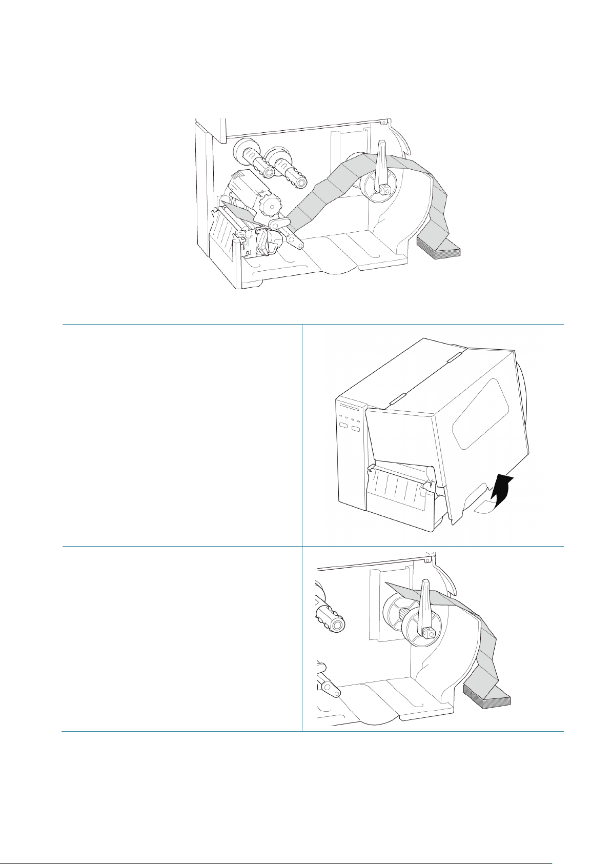
3.4.2 Load External Media
Fan-fold label loading path
1. Open the Media Cover.
2. Insert the media through the External
Label Entry Slot.
25
3. Push the Print Head Release Lever and
thread the label through the Damper,
Media Sensor, and Front Label Guide to
install the media.
Align the Label Roll Guard with the label
width.
4. Move the Media Sensor by adjusting the Media Sensor Position Adjustment Knob. Make sure
the position of the Gap or Black Mark Sensor matches the position of the Gap/Black Mark on
the label.
5. Adjust the Front Label Guide to fix the
media position.
Note
• Make sure you thread the media
through the Media Sensor.
• The sensor locations are marked by
the triangle mark (Gap Sensor)
and the arrow mark (Black Mark
Sensor) at the sensor housing.
• The Media Sensor position is
adjustable. Make sure the position of
the Gap or Black Mark Sensor
matches the position of the
Gap/Black Mark on the label.
Gap Sensor
(shown as )
Black Mark Sensor
(shown as )
26
6. Close the Print Head on both sides and
make sure it locks into place.
7. Set the media sensor type and calibrate
the selected sensor.
Note
Calibrate the Gap/Black Mark Sensor every time you change the media.
For more information about sensor calibration, see section 8.2 Auto-Calibrating the Media
Sensor using the BPM.
27
3.4.3 Load the Media in Peeler Mode (Optional)
1. Open the Media Cover.
2. Slide the Label Roll Guard horizontally to
the end of the Label Supply Spindle, and
then flip down the Label Roll Guard.
3. Place the label roll on the Label Supply
Spindle and then flip the Label Roll Guard
upwards to hold it in place.
Note
Make sure the label print side is facing
up.

28
4. Push the Print Head Release Lever and
thread the label through the Damper,
Media Sensor, and Front Label Guide to
install the media.
5. Move the Media Sensor by adjusting the Media Sensor Position Adjustment Knob. Make sure
the position of the Gap or Black Mark Sensor matches the position of the Gap/Black Mark on
the label roll.
6. Adjust the Front Label Guide to fix the
media position.
Note
• Make sure you thread the media
through the Media Sensor.
• The sensor locations are marked by
the triangle mark (Gap Sensor)
and the arrow mark (Black Mark
Sensor) at the sensor housing.
• The Media Sensor position is
adjustable. Make sure the position of
the Gap or Black Mark Sensor
matches the position of the
Gap/Black Mark on the label roll.
Black Mark Sensor
(shown as )
Gap Sensor
(shown as )
29
7. Close the Print Head on both sides and
make sure it locks into place.
8. Set the media sensor type and calibrate
the selected sensor.
9. Use the Touchscreen to perform the
calibration first, and set the printer mode
to Peeler Mode.
For models without a Touchscreen,
perform the calibration using the BPM.
For more information about sensor
calibration, see section
8.2 Auto-Calibrating the Media Sensor
using the BPM.
Note
1. Calibrate the Gap/Black Mark
Sensor before loading media in
Peeler Mode to avoid paper jams.
2. Make sure you thread the label over
the Media Guide Bar and under the
Damper as shown.
10. Turn the Print Head Release Lever, and
pull approximately 650 mm of the label roll
through the Media Output Slot.
11. Remove some labels leaving only the
liner.
Label
Liner
30
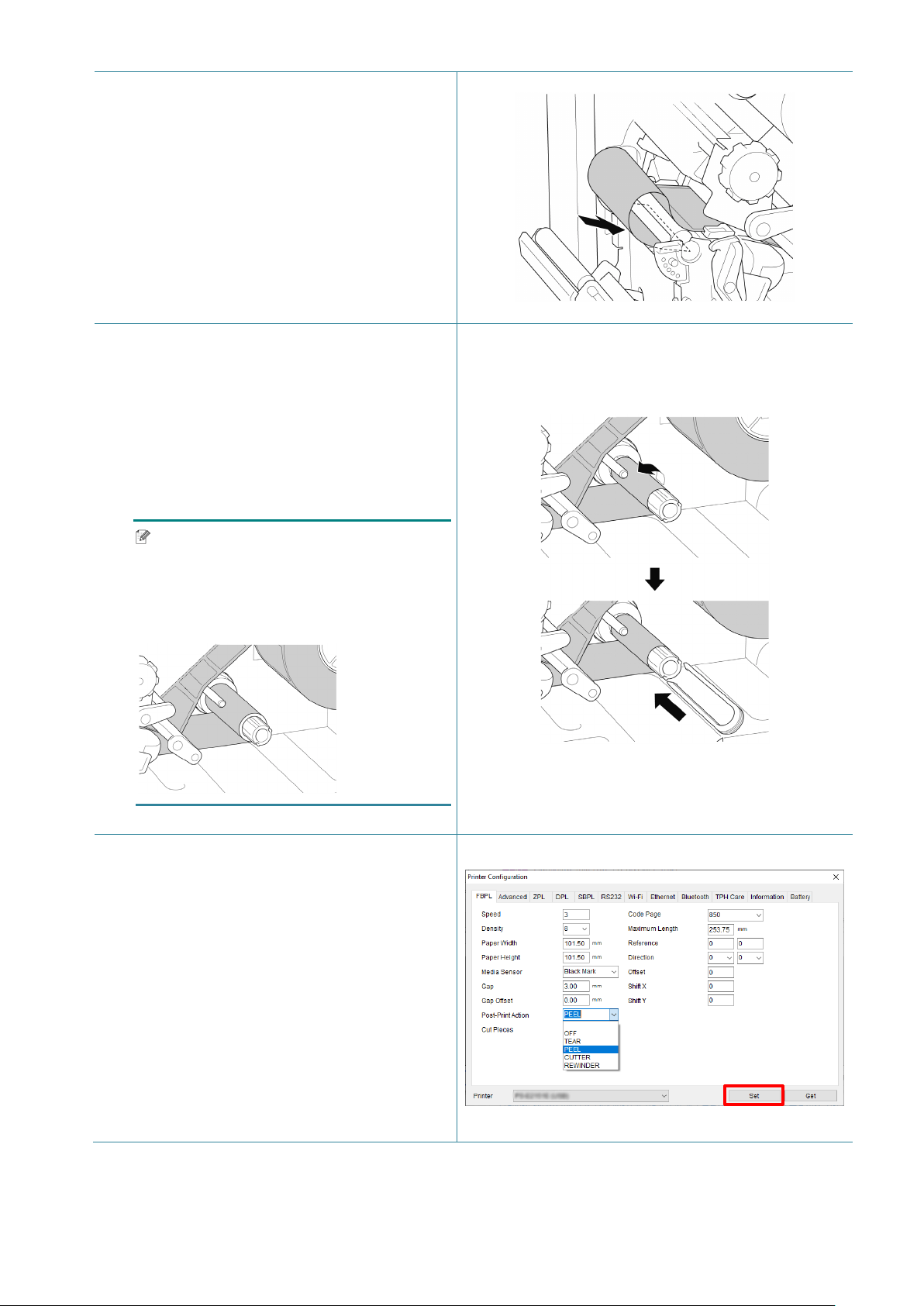
12. Thread the liner through the Label Peeler
Cover Slot.
13. Pull the Liner Securing Clip out from the
Liner Rewind Spindle, and wind the liner
on the Liner Rewind Spindle until the liner
is fully stretched.
14. Insert the Liner Securing Clip into the
Liner Rewind Spindle.
Note
You can also install a paper roll on the
Liner Rewind Spindle to wind the liner
around the paper roll.
15. Set the printer mode to “Peel Off” using
the Main Menu (Main Menu > Setting >
Print Mode > Peel Off) or using the
Brother Printer Management Tool (BPM)
as follows.
a. Start the BPM.
b. Click the Printer Configration button.
c. Click the FBPL tab.
d. Click the PEEL option from the
Post-Print Action drop-down list.
e. Click Set.
31
16. Lock the Print Head Release Lever and
feed one label to test:
For touchscreen models: Tap the Feed
icon in the Main Menu.
For non-touchscreen models: Press the
Feed button.
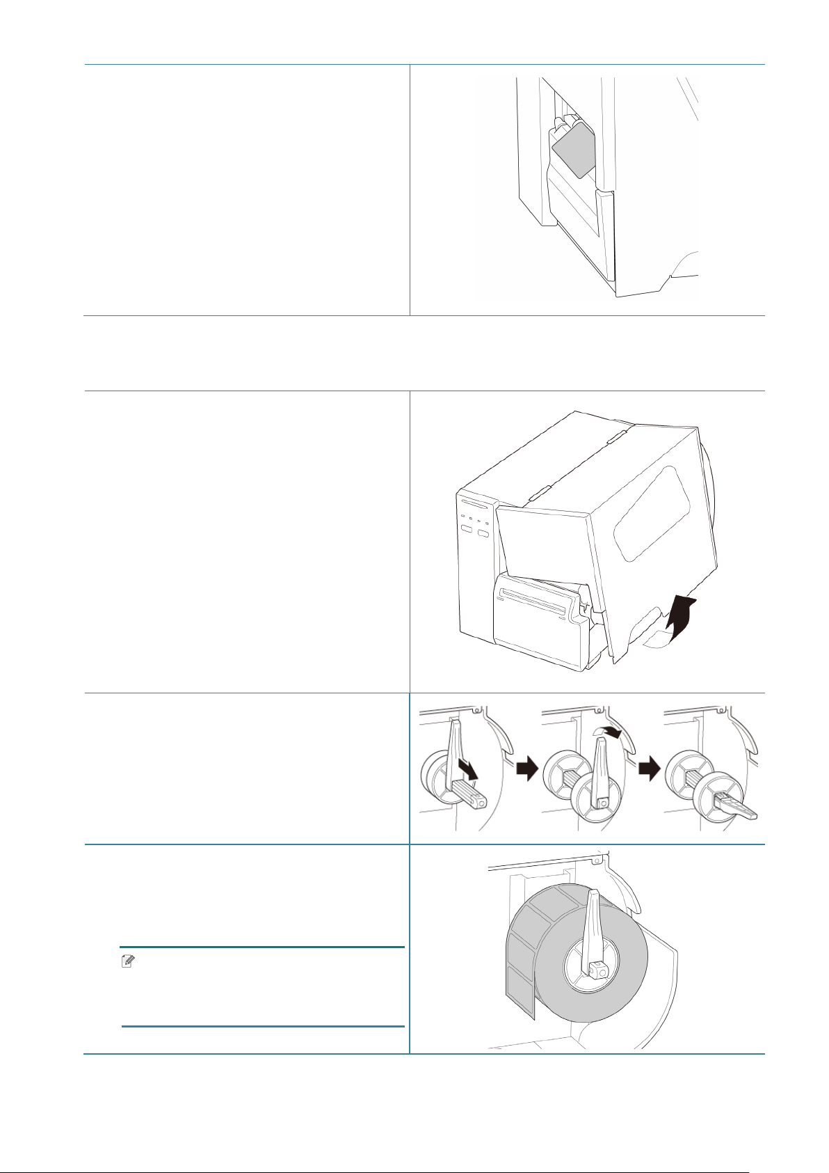
3.4.4 Load Media in Cutter Mode (Optional)
1. Open the Media Cover.
2. Slide the Label Roll Guard horizontally to
the end of the Label Supply Spindle, and
then flip down the Label Roll Guard.
3. Place the label roll on the Label Supply
Spindle and then flip the Label Roll Guard
upwards to hold it in place.
Note
Make sure the label print side is facing
up.
32
4. Push the Print Head Release Lever and
thread the label through the Damper,
Media Sensor, and Front Label Guide to
install the media.
5. Feed the media through the Label Cutter
Cover Slot.
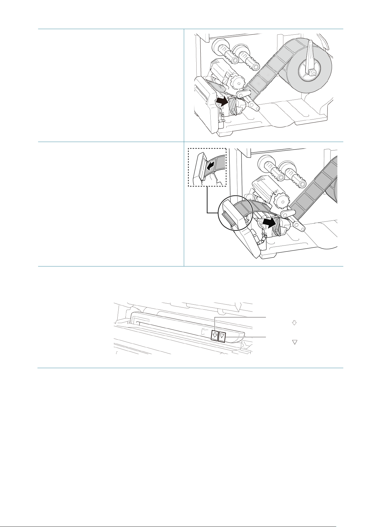
6. Move the Media Sensor by adjusting the Media Sensor Position Adjustment Knob. Make sure
the position of the Gap or Black Mark Sensor matches the position of the Gap/Black Mark on
the label roll.
Black Mark Sensor
(shown as )
Gap Sensor
(shown as )
33
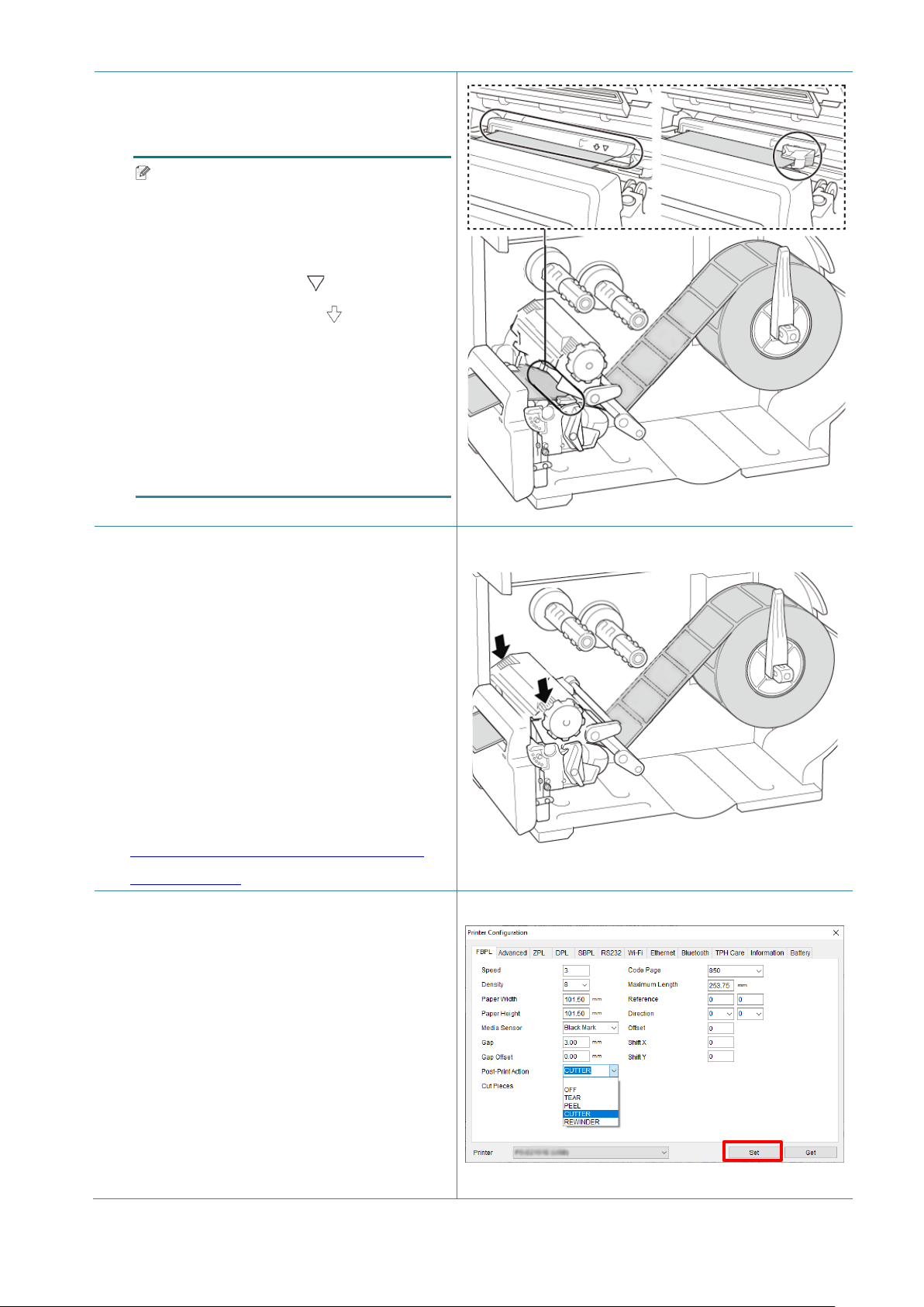
7. Adjust the Front Label Guide to fix the
media position.
Note
• Make sure you thread the media
through the Media Sensor.
• The sensor locations are marked by
the triangle mark (Gap Sensor)
and the arrow mark (Black Mark
Sensor) at the sensor housing.
• The Media Sensor position is
adjustable. Make sure the position of
the Gap or Black Mark Sensor
matches the position of the
Gap/Black Mark on the label roll.
8. Close the Print Head on both sides and
make sure it locks into place.
9. Set the media sensor type and calibrate
the selected sensor.
10. Use the Touchscreen to perform the
calibration first, and set the printer mode
to Cutter Mode.
For models without a Touchscreen,
perform the calibration using the BPM.
For more information about sensor
calibration, see section
8.2 Auto-Calibrating the Media Sensor
using the BPM.
11. Set the printer mode to “Cutter” using the
Main Menu (Main Menu > Setting > Print
Mode > Cutter mode) or using the
Brother Printer Management Tool (BPM)
as follows.
a. Start the BPM.
b. Click the Printer Configration button.
c. Click the FBPL tab.
d. Click the CUTTER option from the
Post-Print Action drop-down list.
e. Click Set.
34
12. Close the Print Head and feed one label to
test:
For touchscreen models: Tap the Feed
icon in the Main Menu.
For non-touchscreen models: Press the
Feed button.
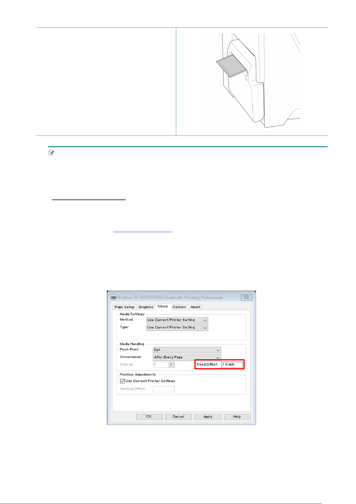
Note
How to adjust the cut position (For Windows)
Using the Printer Driver
1. Open the printers folder.
For more information, see “How to open the Devices and Printers window” on your model's
Manuals page at support.brother.com
.
2. Right-click the printer you want to change the settings for, and then select Printing
Preferences.
3. Select the Stock tab.
4. Enter a positive or negative value (such as “1.0 mm” or “-1.0 mm”) in the Feed Offset field
to fine-tune the cut position.
5. Click Apply, and then click OK to apply the settings.
6. Try to print to confirm the cut position.
35
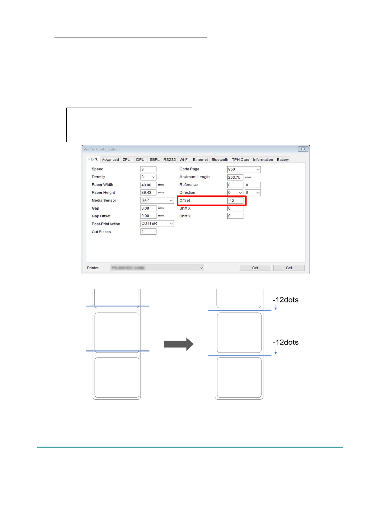
Using BPM (Brother Printer Management Tool)
1. Connect your printer to the computer using a USB cable.
2. Start BPM.
3. Click Printer Configuration, and then select the FBPL tab.
4. Enter a positive or negative value (such as “12” dots or “-12” dots) in the Offset field to
fine-tune the cut position.
You can set values between -999 dots to 999 dots.
For 200 dpi printers: 1 mm = 8 dots
For 300 dpi printers: 1 mm = 12 dots
For 600 dpi printers: 1 mm = 24 dots
(The cut position can be adjusted variously depending on the printer and media you use.)
5. Click Set to apply the settings.
6. Try to print to confirm the cut position.
36
4. Improve Print Quality
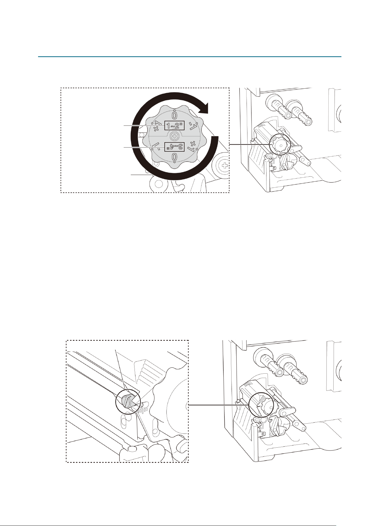
4.1 Adjust Print Head Tension to Improve Print Quality
For the best print quality, adjust the Print Head using the Print Head Tension Adjustment
Knob. Choose one of six levels of tension adjustment depending on the media width you use
(1” - 2” or 3” - 4”).
4.2 Avoid Wrinkled Labels
Wrinkles can occur due to many factors, including media width and thickness, Print Head
pressure balance, ribbon film characteristics, and print density/darkness settings.
4.2.1 Adjust Ribbon Tension (Not available for TJ-4005DN)
To avoid wrinkled labels, adjust the ribbon tension using the Ribbon Tension Adjustment
Screw. Choose one of five levels of tension adjustment.
Suggested Print Head
Tension Values:
For 1" - 2" media width
For 3" - 4" media width
Ribbon Tension Adjustment Screw
37
Description
The ribbon wrinkle occurs from the
lower right to the upper left of the
label.
The ribbon wrinkle occurs from the
lower left to the upper right of the
label.
Wrinkle
Example
Adjustable
Printer Parts
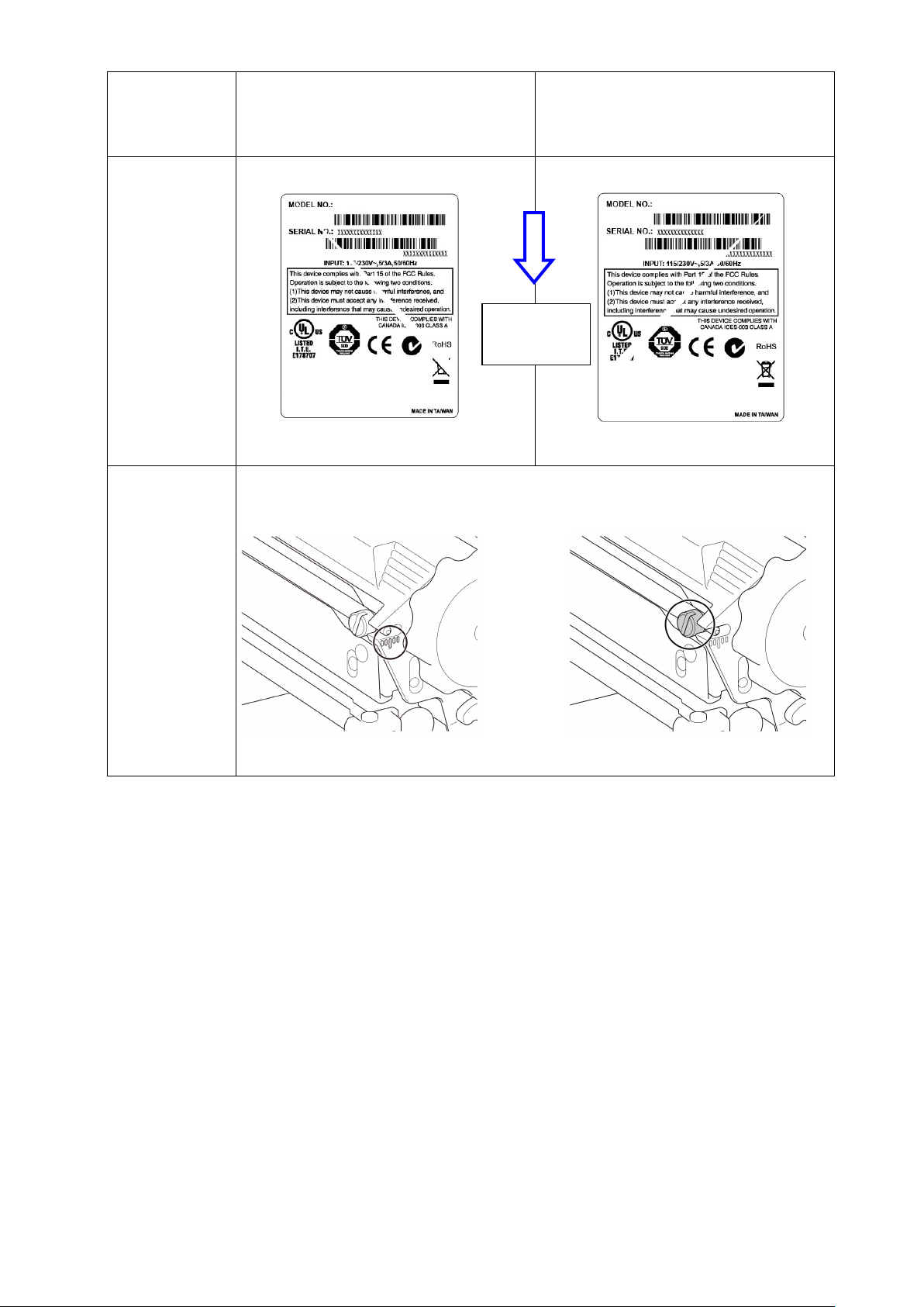
The Ribbon Tension Adjustment Screw has five levels for adjustment. Use a
flat blade screwdriver to change the ribbon tension level.
Ribbon Tension Adjustment Screw
Ribbon Tension Adjustment Scale
Feed
direction
38
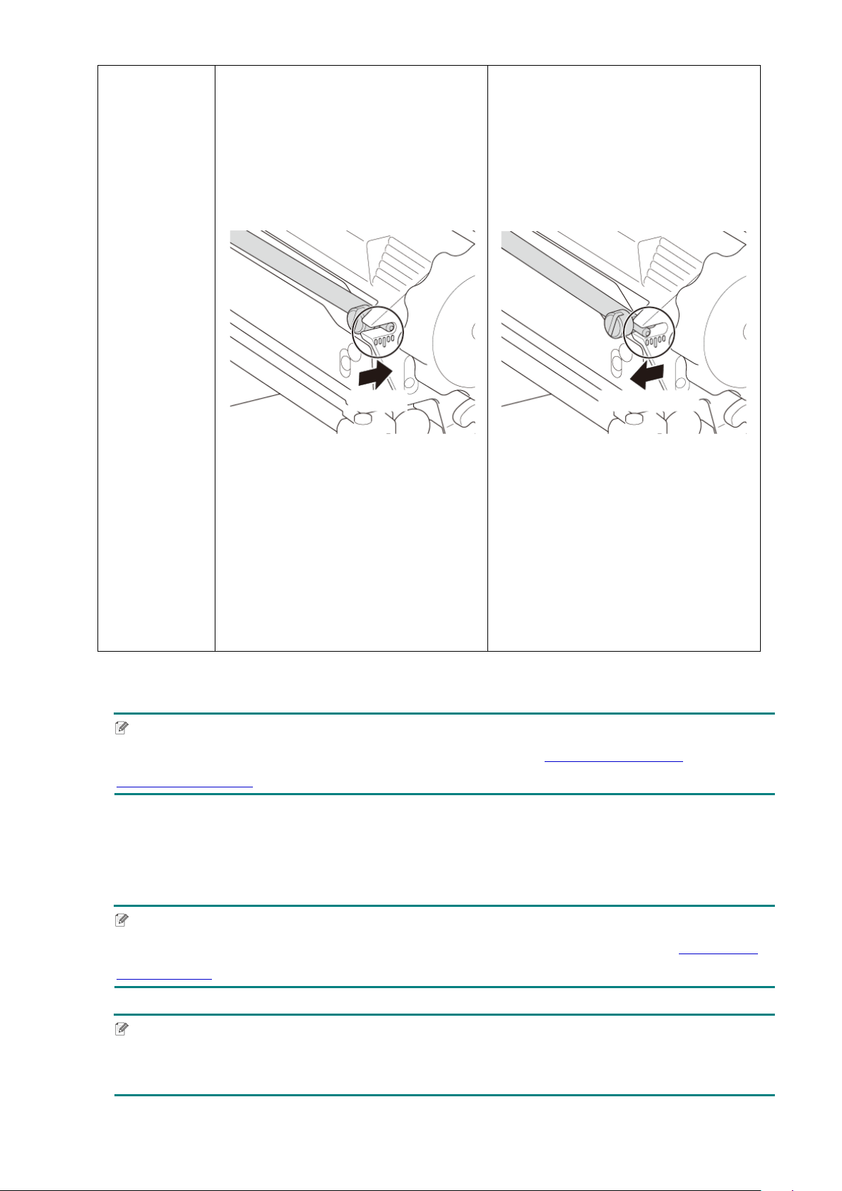
1. Turn the Ribbon Tension
Adjustment Screw clockwise once
per level on the Ribbon Tension
Adjustment Scale and print the
label again to check if the wrinkle is
gone.
2. If the Ribbon Tension Adjustment
Screw is positioned on the
innermost side but the ribbon
wrinkle has not improved, turn the
Print Head Tension Adjustment
Knob once per level at a time,
print
the label again, and check if the
wrinkle is gone.
1. Turn the Ribbon Tension
Adjustment Screw
counterclockwise
once per level on
the Ribbon Tension Adjustment
Scale and print the label again to
check if the wrinkle is gone.
2. If the Ribbon Tension Adjustment
Screw is positioned on the
outermost side but the ribbon
wrinkle has not improved, turn the
Print Head Tension Adjustment
Knob once per level at a time,
print
the label again, and check if the
wrinkle is gone.
4.2.2 Change the Print Density/Darkness Settings
Note
For information about the print density/darkness, see sections 7.1.1 FBPL Settings and
7.1.2 ZPL2 Settings.
4.2.3 Try Different Media
Make sure you load the correct paper.
Note
For more information about the supported paper width and thickness, see section 10 Product
Specifications.
Note
If the wrinkles continue to occur, contact the product manufacturer's customer service or your
local dealer for service.
Clockwise
Counterclockwise

39
5. Printing
5.1 Printer Driver Installation
Note
The model name and serial number are located on the back of the printer.
Make sure you download the correct driver for your model:
• TJ-4005DN: Brother TJ-4005DN
• TJ-4010TN: Brother TJ-4010TN
• TJ-4020TN/TJ-4021TN/TJ-4021TNR: Brother TJ-40
• TJ-4120TN/TJ-4121TN/TJ-4121TNR: Brother TJ-41
The driver installation method depends on the connection type:
USB Connection (Windows/Mac/Linux)
Wi-Fi Network Connection (Windows)
Wired Network Connection (Windows)
5.1.1 USB Connection (Windows/Mac/Linux)
Note
Mac/Linux Users
For more information about driver installation, see the driver installation guide provided with the driver.
1. Connect your printer to the computer using a USB cable.
2. Visit support.brother.com
, go to your model's Downloads page, and download the latest
printer driver and software.
3. Run the Seagull Driver Wizard application and select Install printer drivers and USB.
4. Follow the on-screen instructions.
Note
If you cannot install the printer driver:
Install the printer driver manually:
In the Seagull Driver Wizard application, select Install printer drivers > Others.
Remove the printer drivers:
In the Seagull Driver Wizard application, select Remove printer drivers > Automatically
remove all Drivers by Seagull or Use advanced printer driver removal options.
Reset the printer settings:
Start the BPM, and then click Printer Function > Factory Default.

40
5.1.2 Wi-Fi Network Connection (Windows)
Note
To use Wi-Fi, an optional WLAN Interface (PA-WI-002) is required.
Make sure both your wireless router/access point's and your printer's network settings are correctly
set up. For more information, see the documentation provided with your wireless router/access point,
or contact the router manufacturer, your system administrator, or Internet service provider.
1. Configure the network settings:
- Using the BPM
a. Connect your printer to the computer using a USB cable.
b. Click Printer Configuration > Wi-Fi.
c. Specify SSID, Encryption, and Key (Network Password), and then click Set.
d. Click Get.
e. Click Printer Function > Configuration Page.
The network settings are printed. Confirm that the printer's IP address is correct.
- Using the Touchscreen
a. Select Interface > Wi-Fi.
b. Specify SSID, Security, and Password.
c. When finished, the Wi-Fi icon and printer's IP address appear on the Touchscreen.
2. Visit support.brother.com
, go to your model's Downloads page, and download the latest printer
driver and software.
3. Run the Seagull Driver Wizard application and select Install printer drivers and Network.
4. Select your printer, and then click Next.
5. If your TCP/IP port does not appear in the list, click Create port and select Standard TCP/IP
port > New Port.
6. Type your printer’s IP address and port name, and then click Next.
7. Click Finish.
8. Return to the Specify Port window and select the port you created.
9. Follow the on-screen instructions.
Note
If you cannot install the printer driver:
Remove the printer drivers:
In the Seagull Driver Wizard application, select Remove printer drivers > Automatically
remove all Drivers by Seagull or Use advanced printer driver removal options.
Reset the printer settings:
Start the BPM, and then click Printer Function > Factory Default.

41
5.1.3 Wired Network Connection (Windows)
1. Connect both the printer and the computer to your router/access point using LAN cables. The
printer automatically receives a default IP address and displays it on the Touchscreen. For
models without a Touchscreen, this can be confirmed using the BPM.
2. Visit support.brother.com
, go to your model's Downloads page, and download the latest
printer driver and software.
3. Run the Seagull Driver Wizard application and select Install printer drivers and Network.
4. Select your printer, and then click Next.
5. If your TCP/IP port does not appear in the list, click Create port and select Standard TCP/IP
port > New Port.
6. Type your printer’s IP address and port name, and then click Next.
7. Click Finish.
8. Return to the Specify Port window and select the port you created.
9. Follow the on-screen instructions.
Note
If you cannot install the printer driver:
Remove the printer drivers:
In the Seagull Driver Wizard application, select Remove printer drivers > Automatically
remove all Drivers by Seagull or Use advanced printer driver removal options.
Reset the printer settings:
Start the BPM, and then click Printer Function > Factory Default.
42
5.2 Set the Direct Thermal / Thermal Transfer Print Methods
(Not available for TJ-4005DN)
Using the Printer Driver
1. To set the Direct Thermal method:
Load direct thermal paper (an ink ribbon is not required).
To set the Thermal Transfer method:
Load thermal transfer paper and install an ink ribbon.
2. Open the printers folder.
For more information, see “How to open the Devices and Printers window” on your
model's Manuals page at support.brother.com
.
3. Right-click the printer you want to change the settings for, and then select Printing
Preferences.
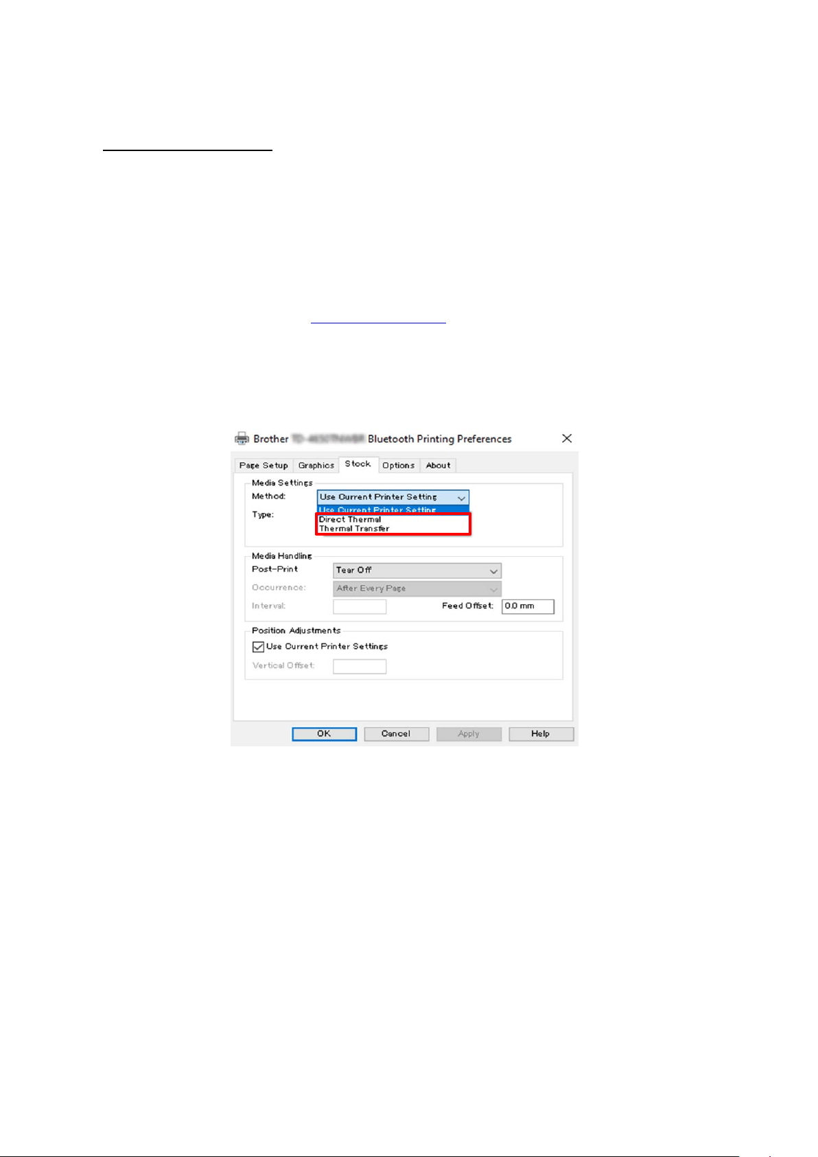
4. Select the Stock tab.
5. Select Direct Thermal or Thermal Transfer from the Method drop-down list.
6. Click Apply, and then click OK to apply the settings.
You can set the Direct Thermal or Thermal Transfer Print Methods by using BPM (Brother
Printer Management Tool) as follows.
1. To set the Direct Thermal method:
Load direct thermal paper (an ink ribbon is not required).
To set the Thermal Transfer method:
Load thermal transfer paper and install an ink ribbon.
2. Connect your printer to the computer using a USB cable.
3. Start BPM.
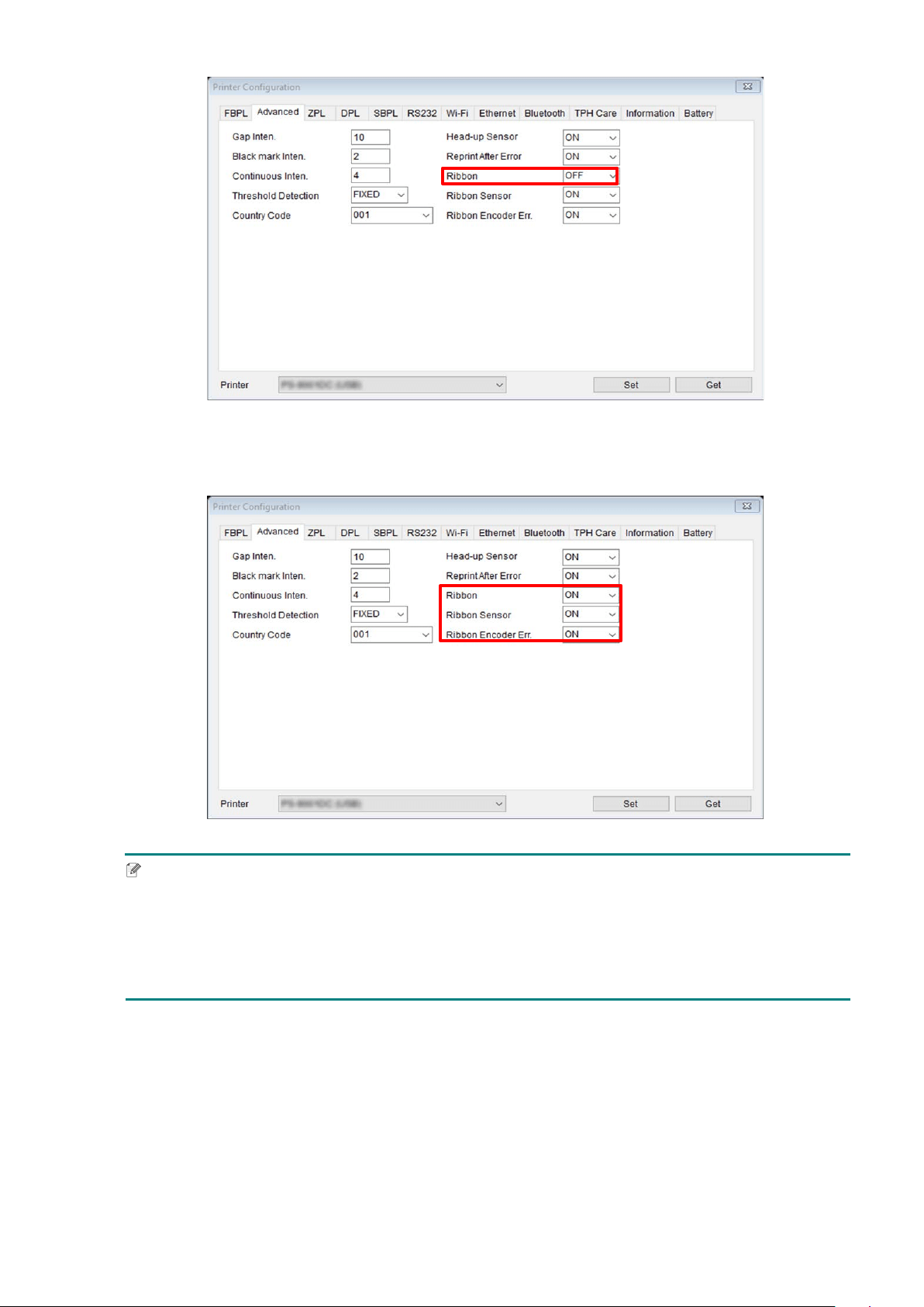
4. Click Printer Configuration, and then select the Advanced tab.
5. When setting the Direct Thermal method:
Select OFF from the Ribbon drop-down list.
43
When setting the Thermal Transfer method:
Select ON from the Ribbon drop-down list, and then select the Ribbon Sensor (for
TJ-series only) and Ribbon Encoder Err. setting you want.
Note
If you select “OFF” from the Ribbon drop-down list, it will deactivate both the ribbon sensor and
the ribbon encoder sensor (even if you have selected “ON” in the Ribbon Sensor and Ribbon
Encoder Err. drop-down list and “ON” is displayed). Select “ON” in the Ribbon drop-down list to
activate the Ribbon Sensor and Ribbon Encode Err. settings.
6 Click Set to apply the settings.
44
5.3 Create and Print Labels Using BarTender
BarTender is a label creation tool, which can be downloaded for free from the product's
page at support.brother.com
.
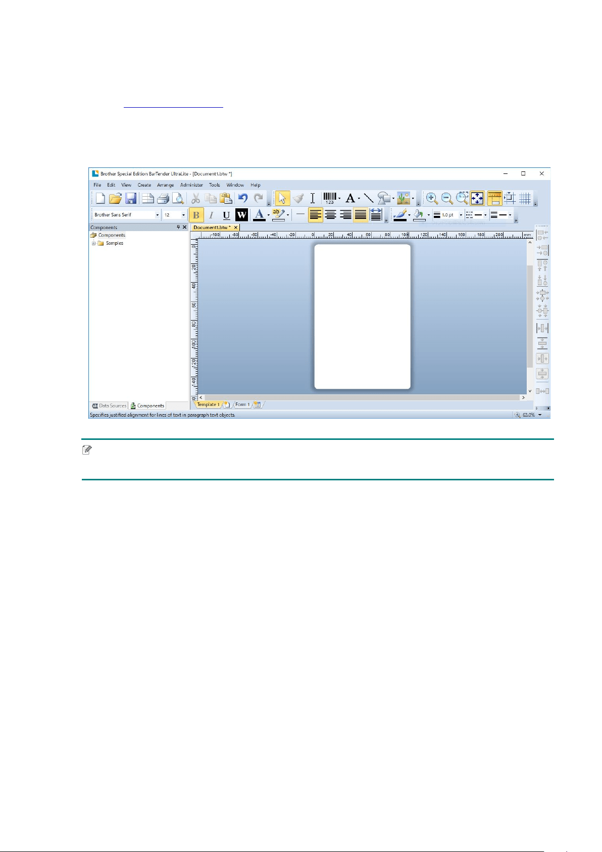
1. Launch BarTender.
2. Follow the on-screen steps to create a label.
Note
For more information on using BarTender, click Help.
3. Click File > Print to print the label.

45
6. Operation
6.1 Power-on Utilities
There are various power-on utilities to set up and test the printer's functions.
TJ-4005DN/TJ-4010TN/TJ-4020TN/TJ-4120TN
Use the power-on utilities to calibrate sensors and initialize the hardware.
Function Instructions
Gap/Black Mark
Sensor Calibration
1. Turn off the printer.
2. Press and hold the Pause Button, and then turn on the Power
Switch.
3. Release the button when the Power LED lights, and the printer
feed
the labels.
Self-test
1. Turn off the printer.
2. Press and hold the Feed Button, and then turn on the Power
Switch.
3. Release the button when the Power LED lights, and the printer
feeds the labels.
Printer initialization
1. Turn off the printer.
2. Press and hold both the Pause and Feed Buttons, and then turn on
the Power Switch.
3. Release the buttons when the Power LED lights.
Note
When printer initialization is complete, calibrate the Gap Sensor
again.
TJ-4021TN/TJ-4021TNR/TJ-4121TN/TJ-4121TNR
Use power-on utilities to set sensor calibration, self-test, and factory default functions.
1. Turn off the label printer.
2. Press and hold the right Selection button, and then turn on the Power Switch.
3. Release the button when the function you want to set or test appears on the
Touchscreen.
46
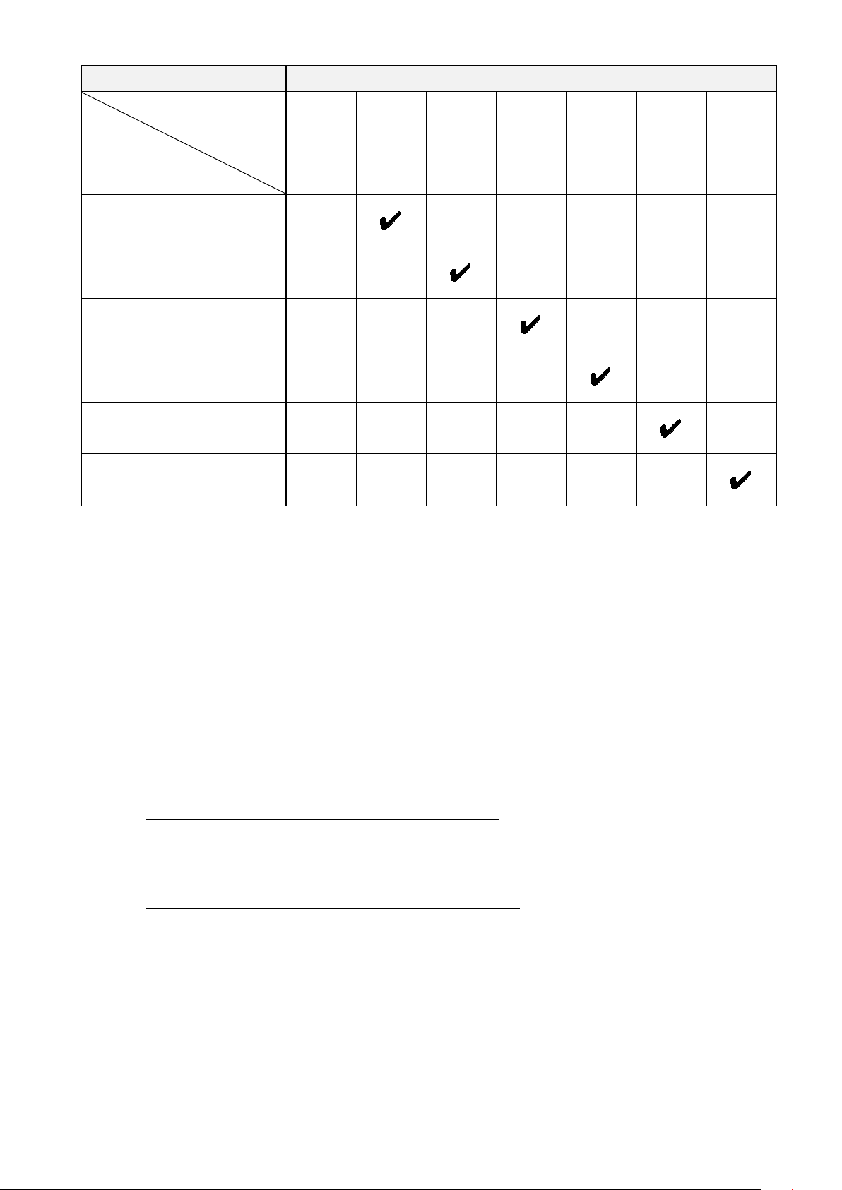
Power-On Utility Power LED Patterns
LED color
Function
Amber (Lit)
Red
(Blinks five
times)
Amber
(Blinks five
times)
Green
(Blinks five
times)
Green/
Amber
(Blinks five
times)
Red/Amber
(Blinks five
times)
Green (Lit)
1. Sensor Calibration (Gap /
black mark sensor)
2. Self-test (And enter Dump
Mode)
3. Factory Default
4. Bline Calibration
5. Gap Calibration
6. READY (Skip AUTO.BAS)
6.1.1 Gap/Black Mark Sensor Calibration
Calibrate the Gap/Black Mark Sensor sensitivity when:
You purchase a new printer.
You change label stock.
The label printer initializes.
To calibrate the Gap/Black Mark Sensors:
1. Turn off the printer.
2. Select the function you want:
- For TJ-4005DN/TJ-4010TN/TJ-4020TN/TJ-4120TN:
a. Press and hold the Pause button, and then turn on the Power Switch.
b. Release the button when the Power LED lights, and the printer feeds the labels.
- For TJ-4021TN/TJ-4021TNR/TJ-4121TN/TJ-4121TNR:
a. Press and hold the right Selection button, and then turn on the Power Switch.
b. Release the button when Sensor Calibration appears on the Touchscreen.
47
Note
The LED color will change as follows:
Amber (lit) red (5 times) amber (5 times) green (5 times) green/amber (5 times)
red/amber (5 times) green (lit)
To select the sensor for calibration, send the correct command to the printer:
For the Gap Sensor: send the GAP command
For the Black Mark Sensor: send the BLINE command
For more information about the available commands, see the FBPL Command Reference
on your model's Manuals page at support.brother.com
.
6.1.2 Gap/Black Mark Sensor Calibration, Self-Test, and Entering Dump
Mode
Calibrate the Gap or Black Mark Sensor if the sensor's settings used in the last print job are not
suitable for the current print job. During the calibration of the Gap/Black Mark Sensor, the printer
detects the label length, prints the internal configuration (self-test), and then enters Dump Mode.
To calibrate the Gap/Black Mark Sensor:
1. Turn off the printer.
2. Select the function you want:
- For TJ-4005DN/TJ-4010TN/TJ-4020TN/TJ-4120TN:
a. Press and hold the Feed button, and then turn on the printer.
b. Release the button when the Power LED lights, and the printer feeds the labels.
- For TJ-4021TN/TJ-4021TNR/TJ-4121TN/TJ-4121TNR:
a. Press and hold the right Selection button, and then turn on the Power Switch.
b. Release the button when Self-test appears on the Touchscreen.
Note
The LED color will change as follows:
Amber (lit) red (5 times) amber (5 times) green (5 times) green/amber (5 times)
red/amber (5 times) green (lit)
3. The printer calibrates the sensor and detects the label length, prints the internal settings,
and then enters Dump Mode.

48
Note
To select the sensor for calibration, send the correct command to the printer:
For the Gap Sensor: send the GAP command
For the Black Mark Sensor: send the BLINE command
For more information about the available commands, see the FBPL Command Reference on
your model's Manuals page at support.brother.com
.
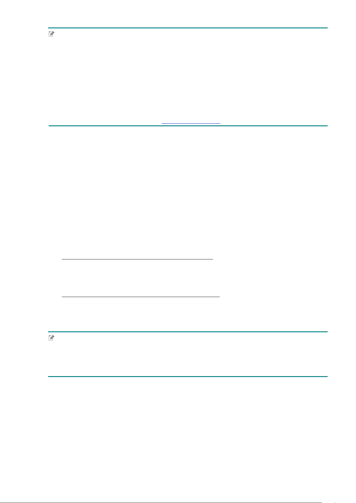
Self-test
Print the printer configuration after you run Gap/Black Mark Sensor calibration. The self-test
printout lists the printer's configuration and available memory, and can indicate if there is any
dot damage on the heater component.
Self-test printout
Model name
Firmware version
Firmware checksum
Printer serial number
Configuration file
System date
System time
Printed mileage (meter)
Cutting counter
Print speed (inch/sec)
Print density
Label size (inch)
Gap distance (inch)
Gap/Black Mark Sensor
sensitivity
Code page
Country code
49
Self-test printout
Print darkness
Print speed (inch/sec)
Label size
Control prefix
Format prefix
Delimiter prefix
Printer power up motion
Print Head close motion
RS232 Serial Port
configuration
RFID frequency band region
Printer name
Mac Address
DHCP
IP Address
Subnet Mask
Gateway
RAW Port
Wi-Fi configuration
50
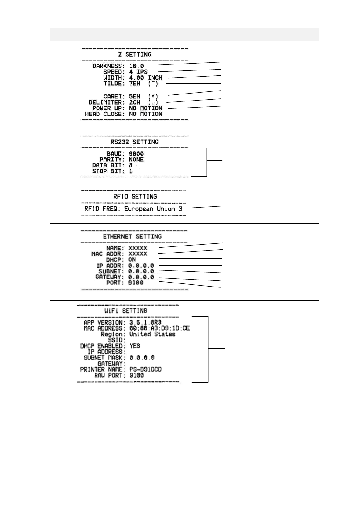
Self-test printout
Number of downloaded files
Total and available memory
space
Print Head check pattern
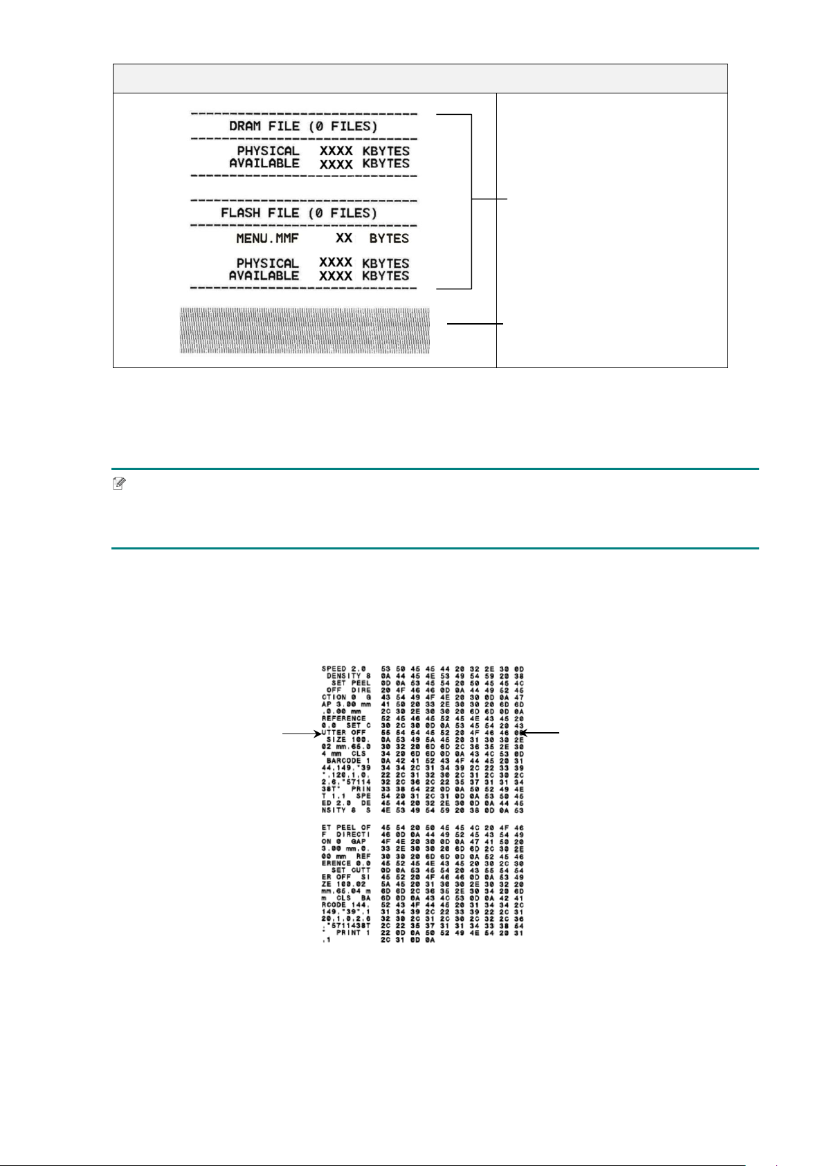
Dump Mode
Note
Dump Mode requires 101.5 mm wide paper.
To resume normal printing, turn the printer off and then on again.
The printer enters Dump Mode after printing the printer configuration. Dump Mode allows users
to verify and debug the printer's programs. The characters in the left column are received from
the printer's system and those in the right column are their hexadecimal representation.
ASCII data
Hexadecimal
representation of the
ASCII data
51
6.1.3 Printer Initialization
Printer initialization clears the printer's DRAM and restores its factory settings.
1. Turn off the printer.
2. Select the function you want:
- For TJ-4005DN/TJ-4010TN/TJ-4020TN/TJ-4120TN:
a. Press and hold the Pause and Feed button, and then turn on the printer.
b. Release the button when the Power LED lights on.
- For TJ-4021TN/TJ-4021TNR/TJ-4121TN/TJ-4121TNR:
a. Press and hold the right Selection button, and then turn on the Power Switch.
b. Release the button when Factory Default appears on the Touchscreen.
Note
The LED color will change as follows:
Amber (lit) red (5 times) amber (5 times) green (5 times) green/amber (5 times)
red/amber (5 times) green (lit)
After the initialization, the following factory settings will be restored:
Parameter Default setting
Speed 127 mm/sec (5 ips) (203 DPI)
76 mm/sec (3 ips) (300 DPI)
Density 8
Label Width 101.5 mm
Label Height 101.5 mm
Sensor Type Gap sensor: TJ-4005DN, TJ-4010TN, TJ-4020TN, TJ-
4021TN,
TJ-4120TN, TJ-4121TN
Black sensor: TJ-4021TNR, TJ-4121TNR
Gap Setting 3 mm
Print Direction 0
Reference Point 0,0 (upper left corner)
Offset 0
Tear Mode On
Peeler Mode Off
Cutter Mode Off
Rewinder Mode Off
Code Page 850
Country Code 001
Clear Flash Memory No
52
6.1.4 Media Sensor Calibration (for the Black Mark Sensor)
1. Turn off the printer.
2. Select the function you want:
- For TJ-4005DN/TJ-4010TN/TJ-4020TN/TJ-4120TN:
The printer calibrates the Gap Sensor and the Black Mark Sensor simultaneously.
a. Press and hold the Pause button, and then turn on the printer.
b. Release the button when the Power LED lights, and the printer feeds the labels.
- For TJ-4021TN/TJ-4021TNR/TJ-4121TN/TJ-4121TNR:
a. Press and hold the right Selection button, and then turn on the Power Switch.
b. Release the button when Bline Calibration appears on the Touchscreen.
Note
The LED color will change as follows:
Amber (lit) red (5 times) amber (5 times) green (5 times) green/amber (5 times)
red/amber (5 times) green (lit)
6.1.5 Media Sensor Calibration (for the Gap Sensor)
1. Turn off the printer.
2. Select the function you want:
- For TJ-4005DN/TJ-4010TN/TJ-4020TN/TJ-4120TN:
The printer calibrates the Gap Sensor and the Black Mark Sensor simultaneously.
a. Press and hold the Pause button, and then turn on the printer.
b. Release the button when the Power LED lights, and the printer feeds the labels.
- For TJ-4021TN/TJ-4021TNR/TJ-4121TN/TJ-4121TNR:
a. Press and hold the right Selection button, and then turn on the Power Switch.
b. Release the button when Gap Calibration appears on the Touchscreen.
Note
The LED color will change as follows:
Amber (lit) red (5 times) amber (5 times) green (5 times) green/amber (5 times)
red/amber (5 times) green (lit)

53
6.1.6 Skip the AUTO.BAS Program
You can upload the AUTO.BAS program to the printer's flash memory so that it runs
automatically at startup, but if you do not want it to run automatically, follow these steps:
1. Turn off the printer.
2. Select the function you want:
- For TJ-4005DN/TJ-4010TN/TJ-4020TN/TJ-4120TN:
Press and hold the Pause and Feed buttons, and then turn on the printer.
- For TJ-4021TN/TJ-4021TNR/TJ-4121TN/TJ-4121TNR:
a. Press and hold the right Selection button, and then turn on the Power Switch.
b. Release the button when READY (Skip AUTO.BAS) appears on the Touchscreen.
Note
The LED color will change in the following order:
Amber (lit) red (5 times) amber (5 times) green (5 times) green/amber (5 times)
red/amber (5 times) green (lit)
3. The printer will start without running the AUTO.BAS program.
54
7. Change Printer Settings using the Touchscreen
(Available for TJ-4021TN/4021TNR/4121TN/4121TNR only.)
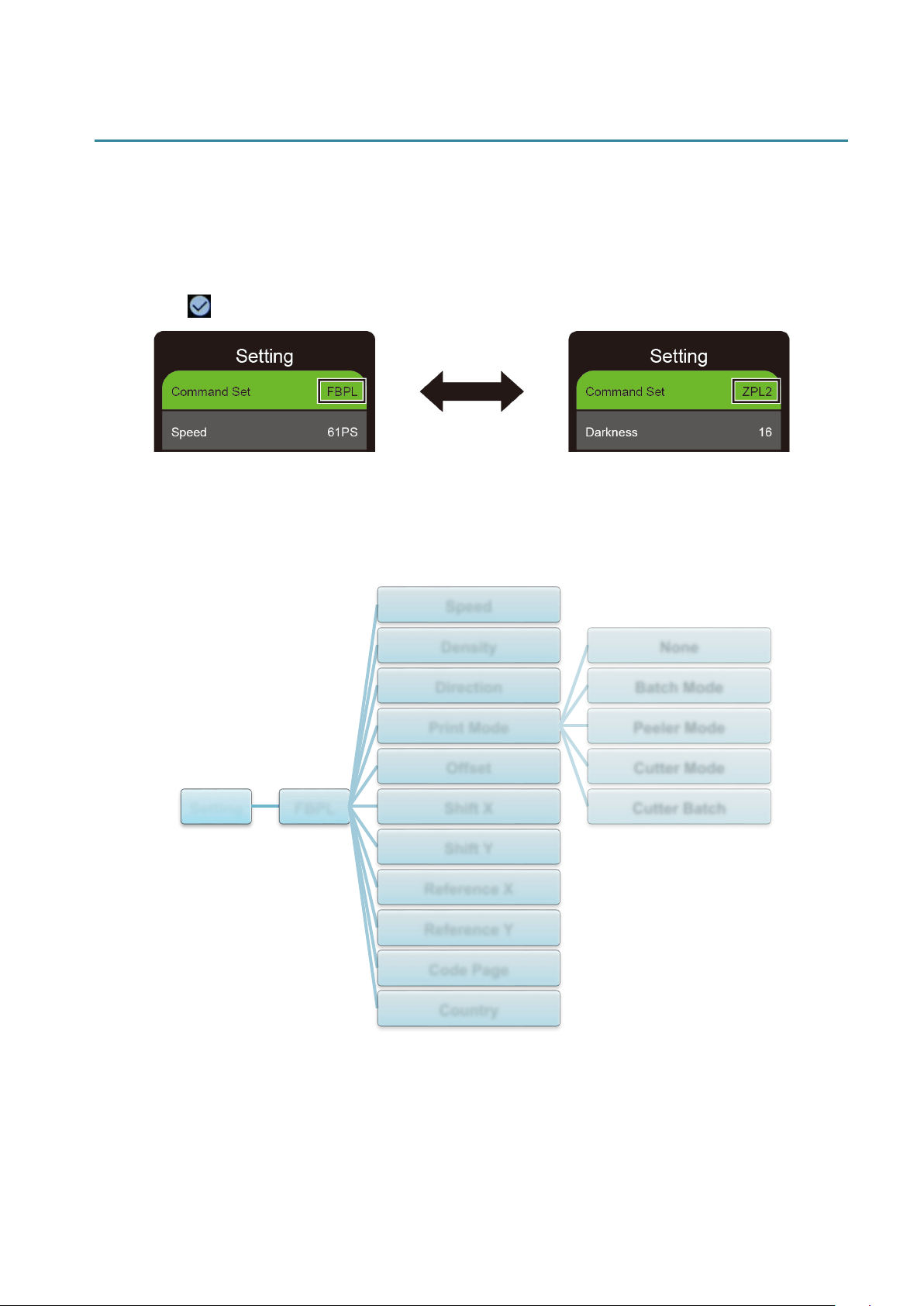
7.1 Setting Menu
1. In the Main Menu, tap Setting.
2. Tap Command Set, and then select the programming language you want.
3. Tap the icon.
7.1.1 FBPL Settings
Available FBPL settings:
Setting FBPL
Speed
Density
Direction
Print Mode
None
Batch Mode
Peeler Mode
Cutter Mode
Cutter Batch
Offset
Shift X
Shift Y
Reference X
Reference Y
Code Page
Country
55
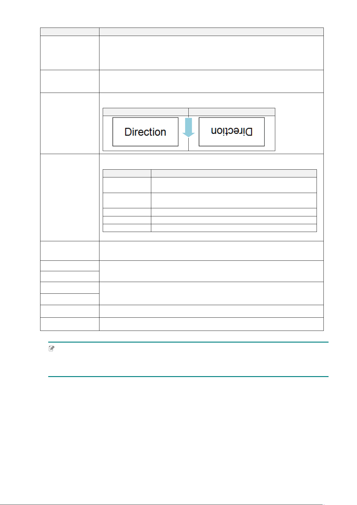
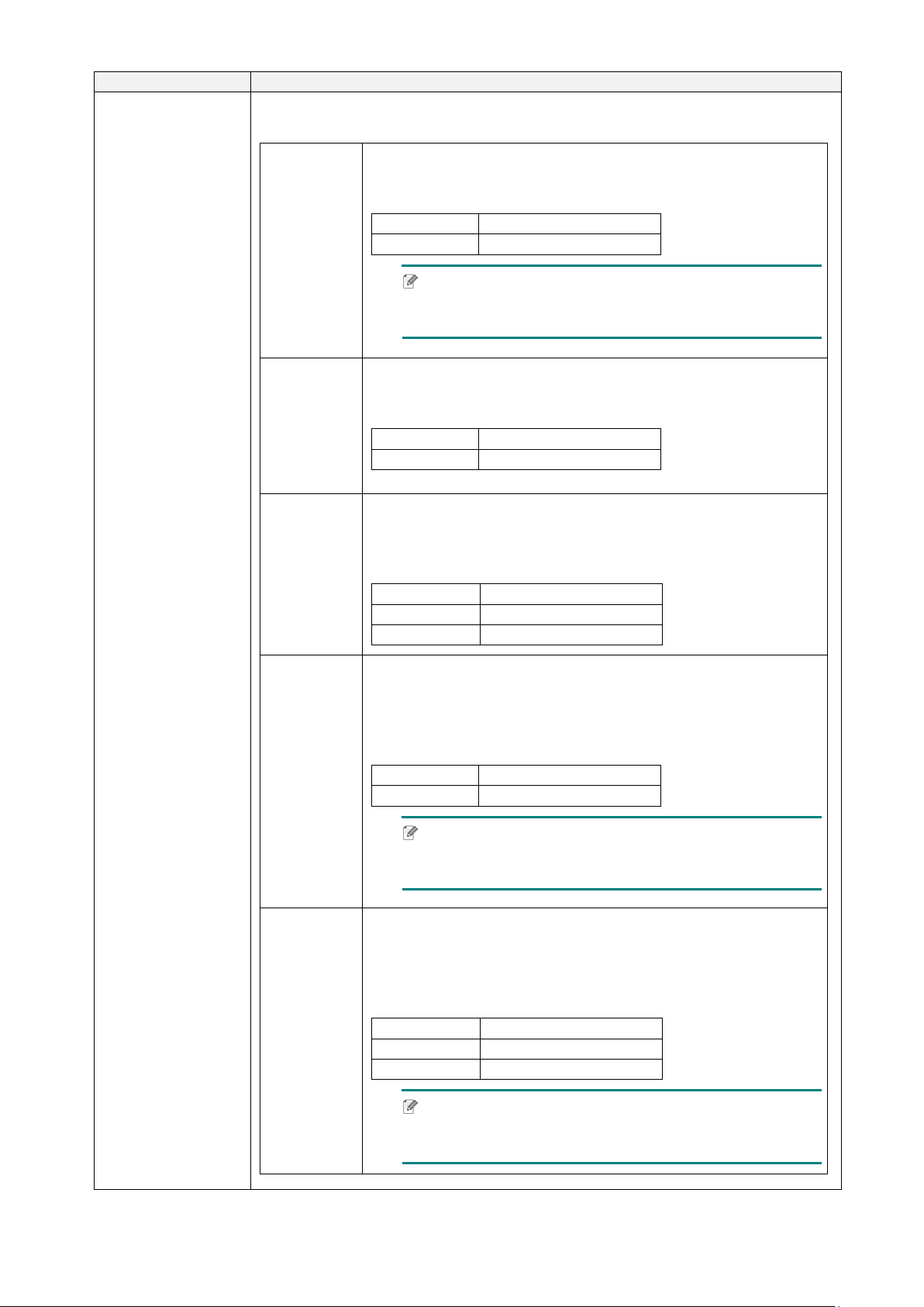
Setting
Description
Speed
Set up the print speed. Settings range from:
1 - 10 for 203 dpi (Default: 5)
1 - 7 for 300 dpi (Default: 3)
Density
Adjust the print darkness/lightness. Settings range from 0 to 15. You may
need to adjust the print density based on the media.
Direction
Specify print direction.
DIRECTION 0
DIRECTION 1
Print Mode
Set the Print Mode.
Print Mode
Description
None
The top of the next label is aligned with the Print Head
burn line (Tear Off Mode).
Batch Mode
When the image is printed, the Gap/Black Mark is fed
through the tear plate for tear away.
Peeler Mode
Enables label Peeler Mode.
Cutter Mode
Enables label Cutter Mode.
Cutter Batch
Cuts the label once at the end of the printing job.
Offset
Fine-tune the media stop location. Settings range from -999 dots to 999
dots.
Shift X
Fine-tune the print position. Settings range from -999 dots to 999 dots.
Shift Y
Reference X
Set the origin of the printer coordinate system horizontally and vertically.
Settings range from 0 dots to 999 dots.
Reference Y
Code Page
Set the international character set code page.
Country
Set the country code. Settings range from 1 to 358.
Note
If printing from the downloaded software/driver, the software/driver commands will overwrite the
settings set from the Touchscreen.
FEED
56
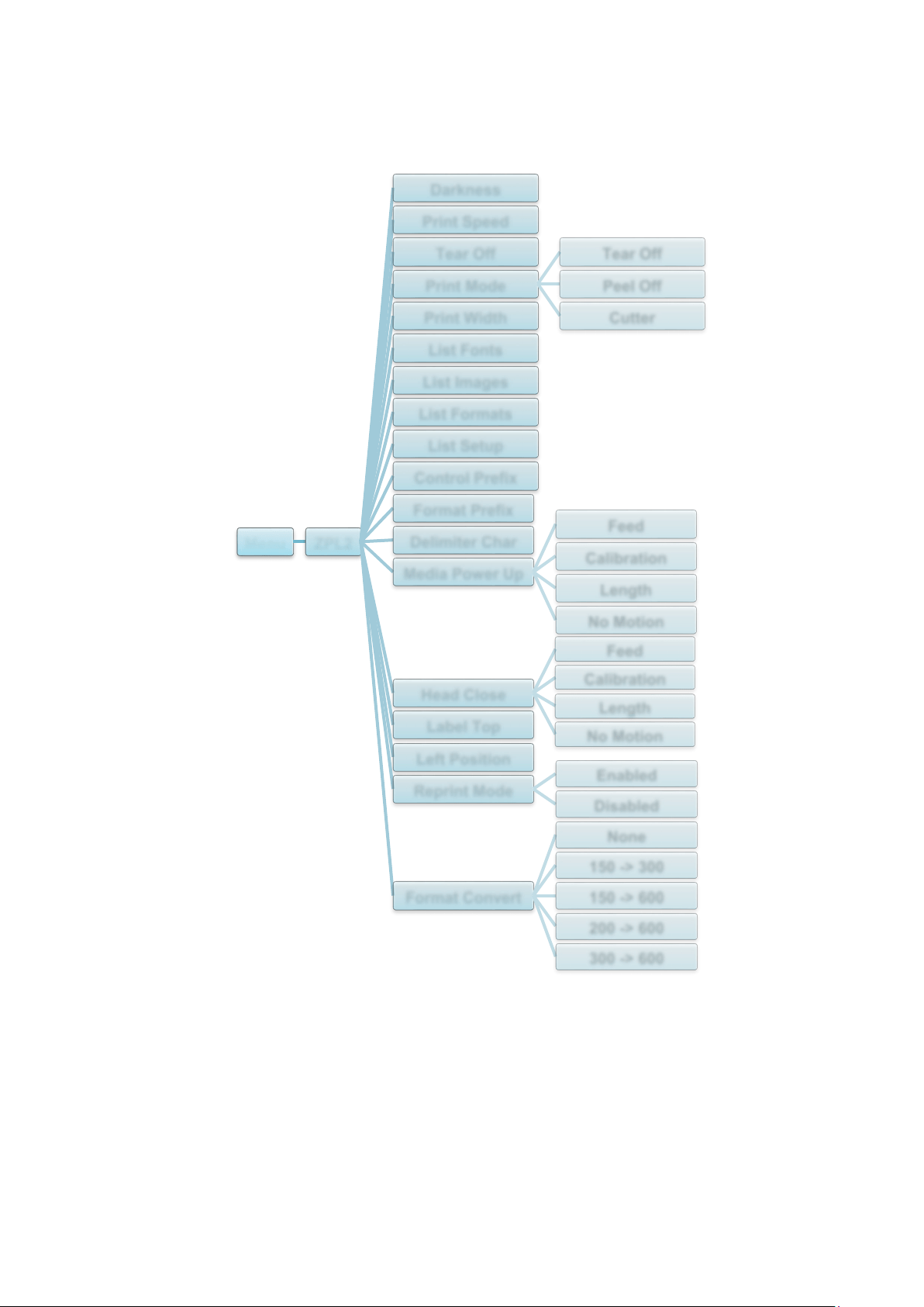
7.1.2 ZPL2 Settings
Available ZPL2 settings:
Menu ZPL2
Darkness
Print Speed
Tear Off
Print Mode
Tear Off
Peel Off
CutterPrint Width
List Fonts
List Images
List Formats
List Setup
Control Prefix
Format Prefix
Delimiter Char
Media Power Up
Feed
Calibration
Length
No Motion
Head Close
Feed
Calibration
Length
No Motion
Label Top
Left Position
Reprint Mode
Enabled
Disabled
Format Convert
None
150 -> 300
150 -> 600
200 -> 600
300 -> 600
57
Setting
Description
Darkness
Set up the print darkness. Settings range from 0 to 30. You may need
to adjust the print density based on the selected media.
Print Speed
Set up the print speed. Settings range from:
2 - 10 for 203 dpi (Default: 4)
2 - 7 for 300 dpi (Default: 3)
Tear Off
Fine-tune the media stop location. Settings range from -120 dots to
120 dots.
Print Mode
Set the print mode.
Print Mode
Description
Tear Off The top of the next label is aligned with the Print
Head burn line.
Peel Off Enable the label Peeler Mode.
Cutter
Enable the label Cutter Mode.
Print Width
Set the print width. Settings range from 2 dots to 999 dots.
List Fonts
Print the current printer fonts list to the label. The fonts can be stored in
the printer’s DRAM, Flash, or optional memory card.
List Images
Print the current printer images list to the label. The images can be
stored in the printer’s DRAM, Flash, or optional memory card.
List Formats
Print the current printer formats list to the label. The formats can be
stored in the printer’s DRAM, Flash, or optional memory card.
List Setup
Print the current printer configuration.
Control Prefix
Set the control prefix character.
Format Prefix
Set the format prefix character.
Delimiter Char
Set the delimiter character.
Media Power Up
Set the media action you want when you turn the printer on.
Action
Description
Feed The printer ejects one label.
Calibration The printer calibrates the sensor levels,
determines the label length, and feeds one label.
Length
The printer determines the label length and feeds
the label.
No Motion
No action.
Head Close
Set the media action when you close the Print Head.
Action
Description
Feed
The printer ejects one label.
Calibration
The printer calibrates the sensor levels,
determines the label length, and feeds one label.
Length
The printer determines the label length and feeds
the label.
No Motion
No action.
58
Setting
Description
Label Top
Adjust the print position vertically on the label. Settings range from
-120 dots to +120 dots.
Left Position
Adjust the print position horizontally on the label. Settings range from
-9999 dots to +9999 dots.
Reprint Mode
Reprint the last label by tapping the Up arrow ( ) button on the
Touchscreen.
Format Convert
Selects the bitmap scaling factor. The first number is the original DPI
value; the second number is the DPI setting you want.
Note
If printing from the downloaded software/driver, the software/driver commands will overwrite the
settings set from the Touchscreen.
59
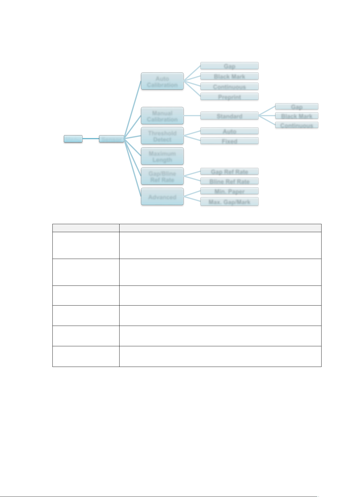
7.2 Sensor Settings
We recommend calibrating the sensors every time you change the media.
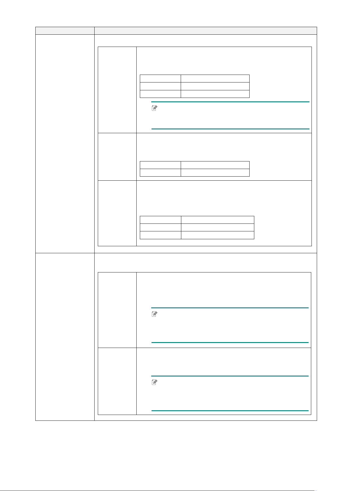
Setting
Description
Auto Calibration
Set the media sensor type and calibrate the selected sensor
automatically. The printer feeds up to three gap labels to calibrate
the sensor sensitivity automatically.
Manual Calibration
If “Automatic” cannot apply to the media, use the “Manual” function
to set the paper length and gap/BLINE size, and then scan the
backing/mark to calibrate the sensor sensitivity.
Threshold Detect
Set the sensor sensitivity to Fixed or Auto.
Maximum Length
Set the maximum length for label calibration.
Gap/Bline Ref Rate
Adjusts sensitivity for gap (spacing) detection on die-cut labels or for
black mark detection.
Advanced
Set the minimum paper length and maximum gap/BLINE length to
calibrate the sensor sensitivity automatically.
Menu Sensor
Auto
Calibration
Gap
Black Mark
Continuous
Preprint
Manual
Calibration
Standard
Gap
Black Mark
Continuous
Threshold
Detect
Auto
Fixed
Maximum
Length
Gap/Bline
Ref Rate
Gap Ref Rate
Bline Ref Rate
Advanced
Min. Paper
Max. Gap/Mark

60
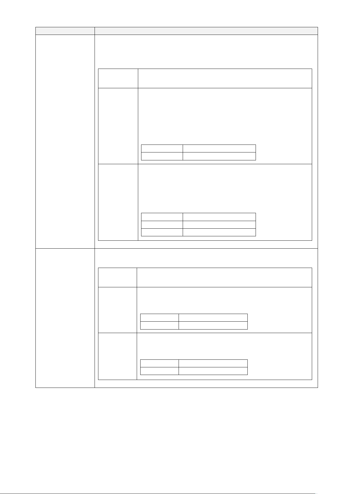
7.3 Interface Settings
Set the printer interface settings.
* Available for TJ-4021TNR and TJ-4121TNR only.
7.3.1 Serial Communication Settings
Set the printer RS-232 settings.
Setting
Description
Baud Rate
Set the RS-232 Baud rate.
Parity
Set the RS-232 Parity.
Data Bits
Set the RS-232 Data bits.
Stop Bit(s)
Set the RS-232 Stop bits.
Menu Interface
Serial
Ethernet
RFID*
Wi-Fi
Menu Interface Serial
Baud Rate
1200 bps
2400 bps
4800 bps
9600 bps
19200 bps
38400 bps
57600 bps
115200 bps
Parity
None
Odd
Even
Data Bits
7
8
Stop Bit(s)
1
2
61
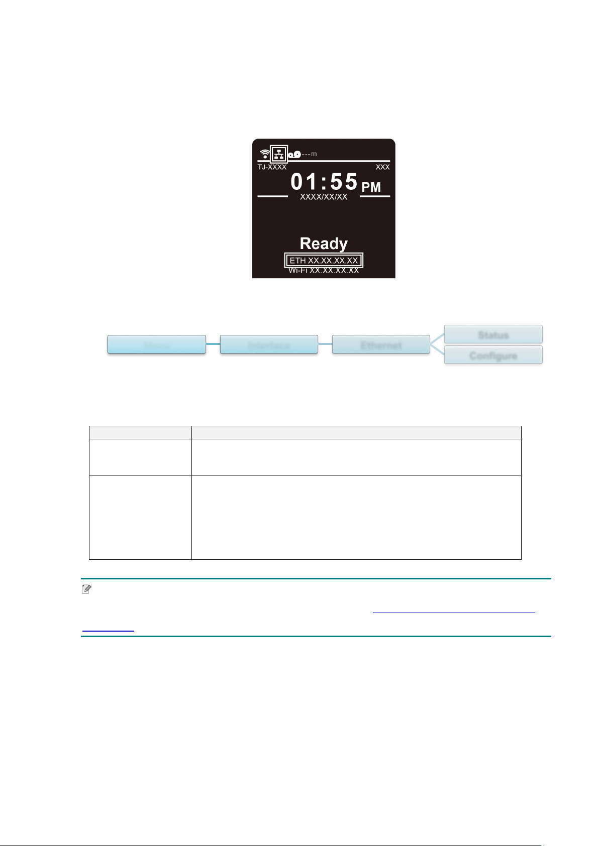
7.3.2 Ethernet Settings
Configure your printer's Ethernet (wired) connection and check its status.
When the Ethernet is connected, the Ethernet icon and IP address appear on the
Touchscreen as shown below.
Item
Description
Status
Check the Ethernet IP address and Mac address setting status.
Configure
DHCP:
Enable (On) or disable (Off) the Dynamic Host Configuration
Protocol (DHCP) network protocol.
Static IP:
Set the printer’s IP address, subnet mask, and gateway.
Note
For information about installing a printer driver, see section 5.1.3 Wired Network Connection
(Windows).
Menu Interface Ethernet
Status
Configure

62
7.3.3 Wi-Fi Settings
Note
To use Wi-Fi, the optional Wi-Fi Interface (PA-WI-002) is required.
Configure your printer's Wi-Fi connection and check its status.
To use this feature, set up the Enterprise configuration using the Brother Printer
Management Tool (BPM). For more information on setting Wi-Fi using the BPM, see the
Brother Printer Management Tool Quick Start Guide on your model's Manuals page at
support.brother.com
.
When the Wi-Fi Interface is connected, the Wi-Fi icon and IP address appear on the
Touchscreen as shown below.
Note
Make sure both your wireless router/access point's and your printer's network settings are
correctly set up. For more information, see the documentation provided with your wireless
router/access point, or contact the router manufacturer, your system administrator, or Internet
service provider.
Menu Interface Wi-Fi
Status
Configure
SSID
Security
Password
63
Item
Description
Status
Check the Wi-Fi IP address and Mac address setting status.
Configure
DHCP:
Enable (On) or disable (Off) the Dynamic Host Configuration
Protocol (DHCP) network protocol.
Static IP:
Set the printer’s IP address, subnet mask, and gateway.
SSID
Set the SSID (Network Name).
Security
Select the Wi-Fi encryption.
Password
Set the password (Network Key).
Note
For information about installing a printer driver, see section 5.1.2 Wi-Fi Network Connection
(Windows).
64
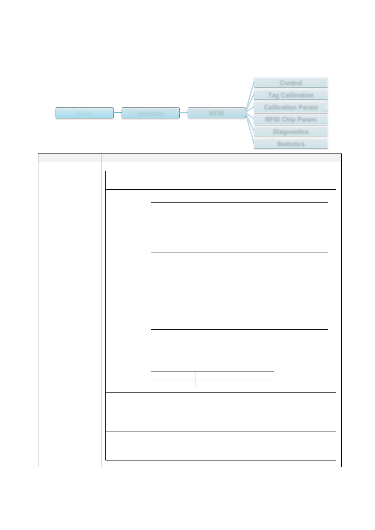
7.3.4 RFID (Radio Frequency Identification) Settings
(Available for TJ-4021TNR and TJ-4121TNR only)
Set the printer RFID settings.
Item
Description
Control
RFID
Active
Select “Enable” to enable the RFID encoder module.
Error
Handling
Select the error handling mode for RFID errors.
Overstrike
(Default)
Each incorrectly processed label prints with
the Overstrike
pattern, and the form retries
on a new label until the Label Retry
count is
exhausted. Whether an error message
appears or the label gets reprinted
depends on the Max Retry Error
setting.
None No specific action is taken when a tag fails
to be
programmed.
Stop The printer will
halt and display the error
message “RFID Error: Check Media”. The
label is discarded and reprinting of the label
must be
initiated from the host. When the
error is cleared, the label with the
incorrect
tag moves forward until the next label is in
position to be
printed.
Label
Retry
Specifies the number of label retries that the RFID
encoder
will attempt before declaring a fault. This may indicate a
problem with the RFID encoder, the printer setup, or the
label stock.
Minimum
1
Maximum
10 (Default)
Max Retry
Error
Determines if errors occur when the Label Retry count is
exceeded.
EPC Write
Ctrl
Controls how the printer encodes the RFID tag EPC
field.
Non-RFID
Warning
Displays a warning if the printer receives a print job that
does not contain any RFID commands when RFID media is
installed in the printer.
Menu Interface RFID
Control
Tag Calibration
Calibration Param
RFID Chip Param
Diagnostics
Statistics
65
Item
Description
Tag Calibration
This submenu is used to perform an RFID calibration. You must perform a
tag calibration when installing a new tag in the printer. RFID calibration
determines the RFID chip type, the write/read power, program position, and
the length of the EPC/User field.
Do RFID
Calibrate
Performs the RFID calibration.
Execute it every time you change the RFID tag type.
Num Label
for
Calibration
Determines the number of tags to use for calibration.
However, this value does not include tags moved when
seeking gaps during the calibration process. Depending on
the difficulty in calibrating the installed tags, the printer may
use more or fewer labels, but generally, the greater the
number selected in this menu, the more tags will be used
to determine the calibration result.
Minimum
3 (Default)
Maximum
7
Test EPC
Length
Determines the size of the EPC data that will be used to
perform the RFID calibration. This length can be increased
to improve the accuracy of the RFID calibration, but it
should not be increased to a value greater than the
maximum EPC length that the current Tag Type can
support.
Minimum
16
Maximum
256
Default
96
Calibration
Param
Contains the settings used for optimal tag encoding. These parameters can
be obtained automatically through RFID calibration.
Tag
Position
Determines how far the RFID tag encoding position of the
currently installed tag should be offset from Top of Form.
Write
Power
Specifies the write power level to be used in the RFID
encoder. Normally, this value is set automatically by the
RFID calibration process and should not be changed.
Minimum
1
Maximum
30
Read
Power
Specifies the read power level to be used in the RFID
encoder. Normally, this value is set automatically by the
RFID calibration process and should not be changed.
Minimum
1
Maximum
30
66
Item
Description
RFID Chip Param
These settings are used to configure the system when custom RFID tags are
required.
USR Size
Specifies the USR block bytes size within the RFID tag
memory. Normally, this value is set automatically by the
RFID calibration process and should not be changed.
Minimum
0 (Default)
Maximum
256
Note
This value is hidden if Higgs 3 tags are detected, and
the Higgs 3 USR Len menu is shown instead.
USR
Address
Specifies the starting location of the USR block within the
RFID tag memory. Normally, this value is set automatically
by the RFID calibration process and should not be changed.
Minimum
0 (Default)
Maximum
32
TID Size
Indicates the size of the memory block within the RFID tag
memory that contains the Tag ID. Normally, this value is set
automatically by the RFID calibration process and should
not be changed.
Minimum
0
Maximum
12
Default
8
Higgs 3
USR Len
Higgs 3 tags differ from other RFID tags in that their memory
bank size is not fixed. To accommodate EPC lengths longer
than 96 bits, Higgs 3 borrows memory from the USR bank.
This read-only menu indicates the size in bits of the USR
block within the RFID tag memory.
Minimum
128
Maximum
512 (Default)
Note
This menu will only be shown if a Higgs 3 tag is
detected.
Higgs 3
EPC Len
Higgs 3 tags differ from other RFID tags in that their memory
bank size is not fixed. To accommodate EPC lengths longer
than 96 bits, Higgs 3 borrows memory from the USR bank.
This menu item allows you to select the number of bits
dedicated to the EPC block within the RFID tag memory.
Minimum
96
Maximum
480
Default
96
Note
This menu will only be shown if a Higgs 3 tag is
detected.
67
Item
Description
RFID Chip Param
Tag
Length
Specifies the EPC block bytes size within the RFID tag
memory. This value is set automatically by the RFID
calibration process and should not be changed.
Minimum
8
Maximum
62
Default
12
Note
This value is hidden if Higgs 3 tags are detected, and
the Higgs 3 EPC Len menu is shown instead.
EPC
Address
Specifies the starting location of the EPC block within the
RFID tag memory. Normally, this value is set automatically
by the RFID calibration process and should not be changed.
Minimum
0 (Default)
Maximum
32
Block Size
Specifies the maximum number of bytes written to the USR
block within the RFID tag memory at one time. Normally,
this value is set automatically by the RFID calibration
process and should not be changed.
Minimum
0
Maximum
32
Default
8
Diagnostics
These settings are used to run test procedures to help determine the
accuracy of the RFID system and troubleshoot it.
Read Tag
Reads the tag in range of the internal RFID coupler and
reports the tag data to the debug port and displays it on the
Touchscreen. It is primarily intended for development
verification by checking that the system is working.
Note
This setting does not position the RFID tag over the
coupler. Make sure to position the tag over the coupler
to receive an accurate reading.
Read Tag
& Eject
This setting works exactly the same as Read Tag, except
that after the printer reads the tag, it feeds the label to the
next top-of-form.
Note
This setting does not position the RFID tag over the
coupler. Make sure to position the tag over the coupler
to receive an accurate reading.
68
Item
Description
Diagnostics
Read USR
Reads the User Memory bank of the tag in range of the
internal RFID coupler and reports the data to the debug
port and displays it on the Touchscreen. It is primarily
intended for development verification by checking that the
system is working.
Note
This setting does not position the RFID tag over the
coupler. Make sure to position the tag over the coupler
to receive an accurate reading.
Read TID
Reads the Tag ID (TID) from the tag in range of the
internal
RFID coupler and displays the value read in the Tag ID
menu.
Note
This setting does not position the RFID tag over the
coupler. Make sure to position the tag over the coupler
to receive an accurate reading.
Tag ID
Displays the first Tag ID (TID) read since power-up, or if
using the Read TID menu, the most recently read TID. If no
tag is in range of the internal RFID coupler, “Unknown”
appears on the Touchscreen.
Read PC
Reads the PC (Protocol Control) field from an RFID tag in
range of the internal RFID coupler and displays the value
read in the Tag PC menu.
Note
This setting does not position the RFID tag over the
coupler. Make sure to position the tag over the coupler
to receive an accurate reading.
Tag PC
Displays the last PC (Protocol Control) field read from an
RFID tag. If no tag is in range of the internal RFID coupler,
“Unknown” appears on the Touchscreen.
Write EPC
with 1s
Writes all ones to the tag in range of the internal RFID
coupler. It is primarily intended for development verification
by checking that the system is working.
Note
This setting does not position the RFID tag over the
coupler. Make sure to position the tag over the coupler
to receive an accurate writing.
Write EPC
with 2s
Writes all twos to the tag in range of the internal RFID
coupler. It is primarily intended for development verification
by checking that the system is working.
Note
This setting does not position the RFID tag over the
coupler. Make sure to position the tag over the coupler
to receive an accurate writing.
69
Item
Description
Statistics
These settings are generally read-only and used to collect and report
statistics on how the RFID system is reporting on print jobs sent to the
printer.
Tag Write
Count
Displays the number of tags attempted to be written since
the last Clear Tag Stat operation has been initiated.
Tag Failed
Count
Displays the number of failed RFID tags since the last Clear
Tag Stat operation has been initiated.
Tag Read
Count
Displays the number of tags read since the last
Clear Tag
Stat operation.
Clear Tag
Stat
Clears the Count menu items in this submenu.
RFID
Reader
F/W
(Available for TJ-4021TNR and TJ-4121TNR only)
Displays the RFID firmware version installed in the encoder.
RFID
Reader
Hd/W
(Available for TJ-4021TNR and TJ-4121TNR only)
Displays the RFID hardware version installed in the
encoder.
70
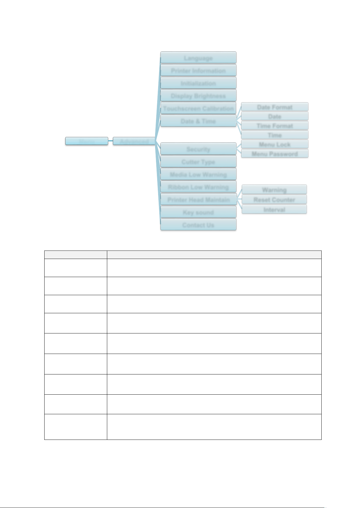
7.4 Advanced Settings
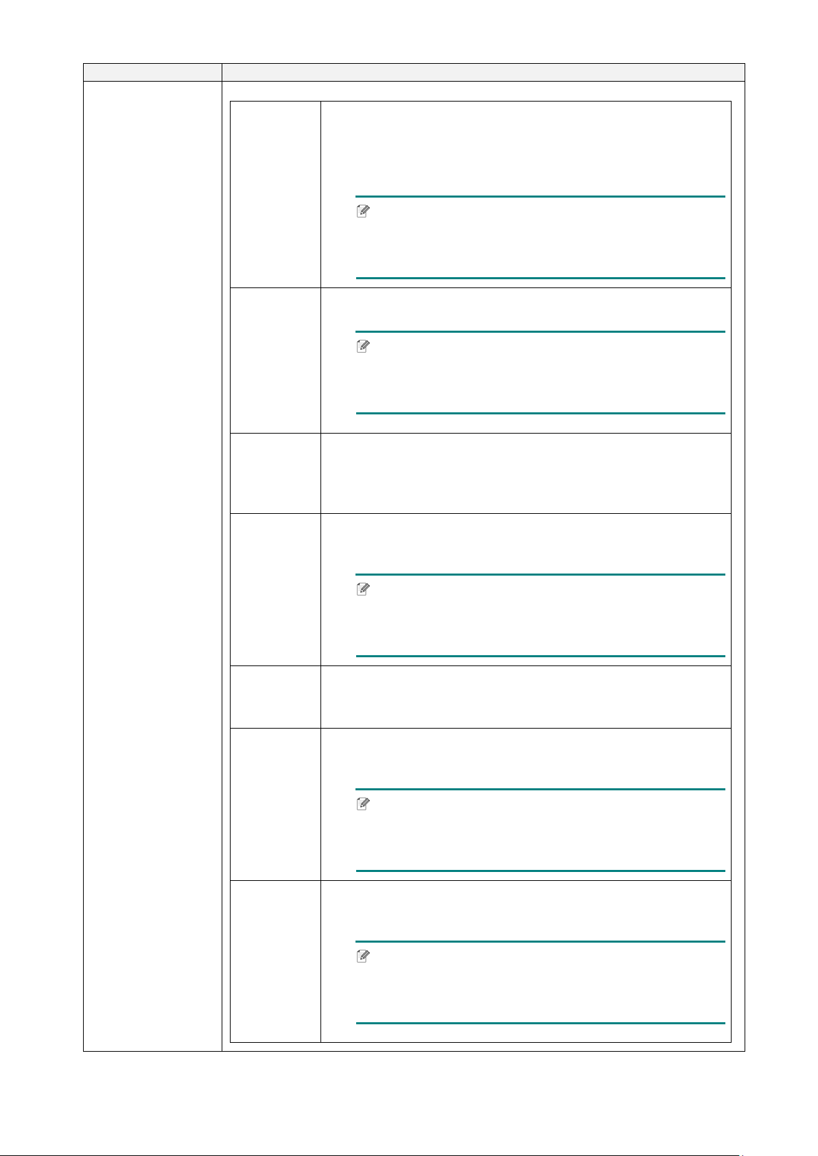
Item
Description
Language
Specify the Touchscreen language.
Printer
Information
Check the printer serial number, printed mileage (in./m), number of
printed labels (pcs), and cutting counter.
Initialization
Restore the printer settings to the default settings.
Display
Brightness
Adjust the Touchscreen brightness (settings range from 0 to 100).
Touchscreen
Calibration
Calibrate the Touchscreen.
Date & Time
Adjust the date and time displayed on the Touchscreen.
Security
Set the password for locking the menu or favorites. The default
password is 8888.
Cutter Type
Set the Cutter Type.
Media Low
Warning
Set the Media Low Warning message.
Menu Advanced
Language
Printer Information
Initialization
Display Brightness
Touchscreen Calibration
Date & Time
Date Format
Date
Time Format
Time
Security
Menu Lock
Menu Password
Cutter Type
Media Low Warning
Ribbon Low Warning
Printer Head Maintain
Warning
Reset Counter
Interval
Key sound
Contact Us
71
Item
Description
Ribbon Low
Warning
Set the Ribbon Low Warning message. For example, if you set the
value at 30 m, when the ribbon capacity is less than 30 m, the
icon appears in red.
TJ-4020TN/TJ-4120TN: 30 m (Fixed)
TJ-4021TN/TJ-4021TNR/TJ-4121TN/TJ-4121TNR: 10 m - 100 m
(Customisable)
Printer Head
Maintain
Check the Print Head status and maintenance notifications.
Item
Description
Warning
Enable or disable the Print Head cleaning warning. If
this setting is enabled and the Print Head has
reached the setting mileage limit, a warning appears
on the Touchscreen to remind you to clean the Print
Head. The default setting is “Disable”.
Reset
Counter
Reset the Print Head mileage warning after the Print
Head has been cleaned.
Interval
Set the mileage for when to display the Print Head
cleaning warning. You must enable the “TPH
warning lock” to use it. The default setting is 1 km.
Key sound
Enable or disable the button press sound.
Contact us
Displays a QR code to access the Brother Support website at
support.brother.com
using a mobile device.
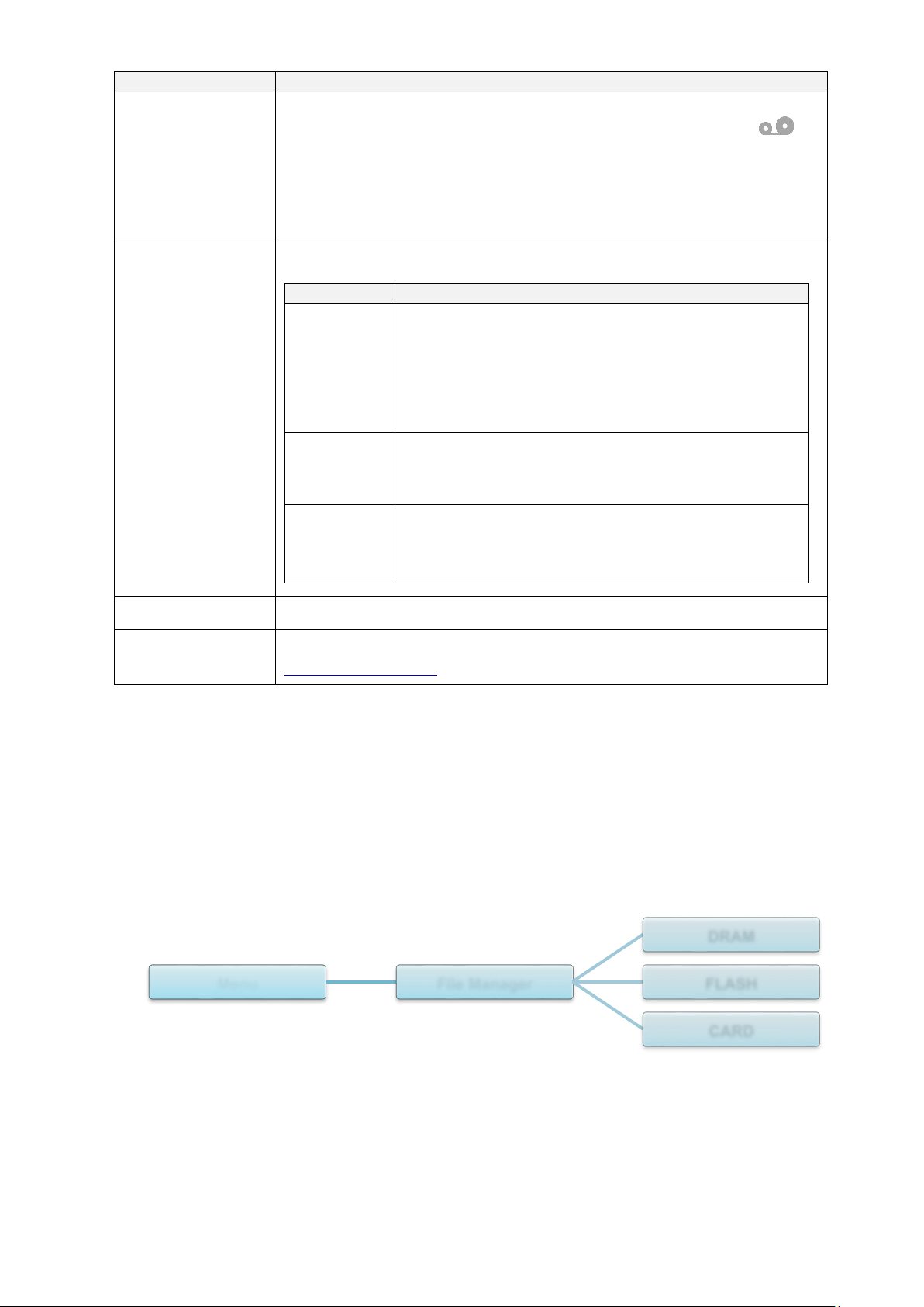
7.5 File Manager
Check the printer's available memory, show the files list, delete the files, or run the files that
are saved in the printer's DRAM/Flash/Card memory.
Menu File Manager
DRAM
FLASH
CARD
72
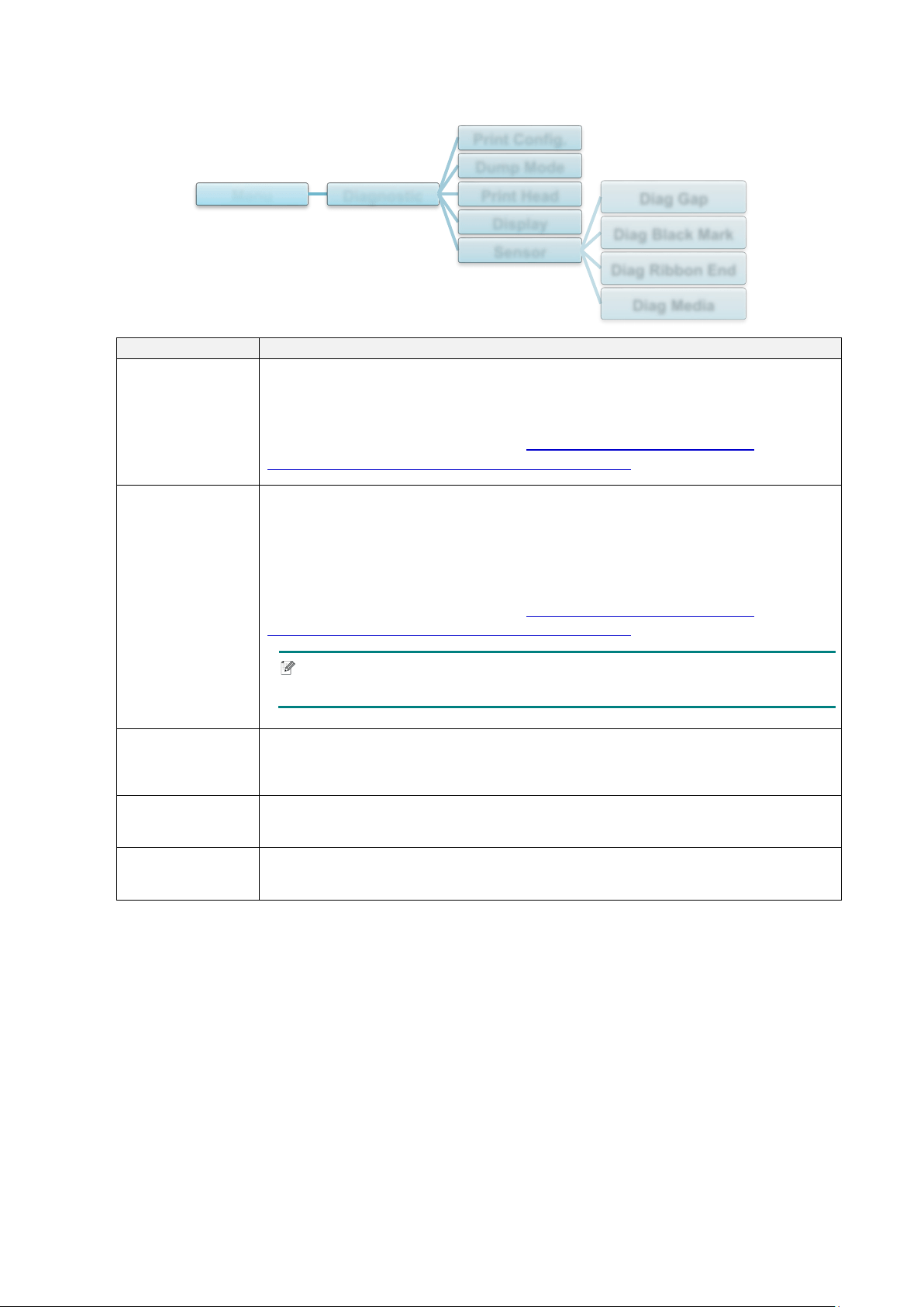
7.6 Diagnostic Functions
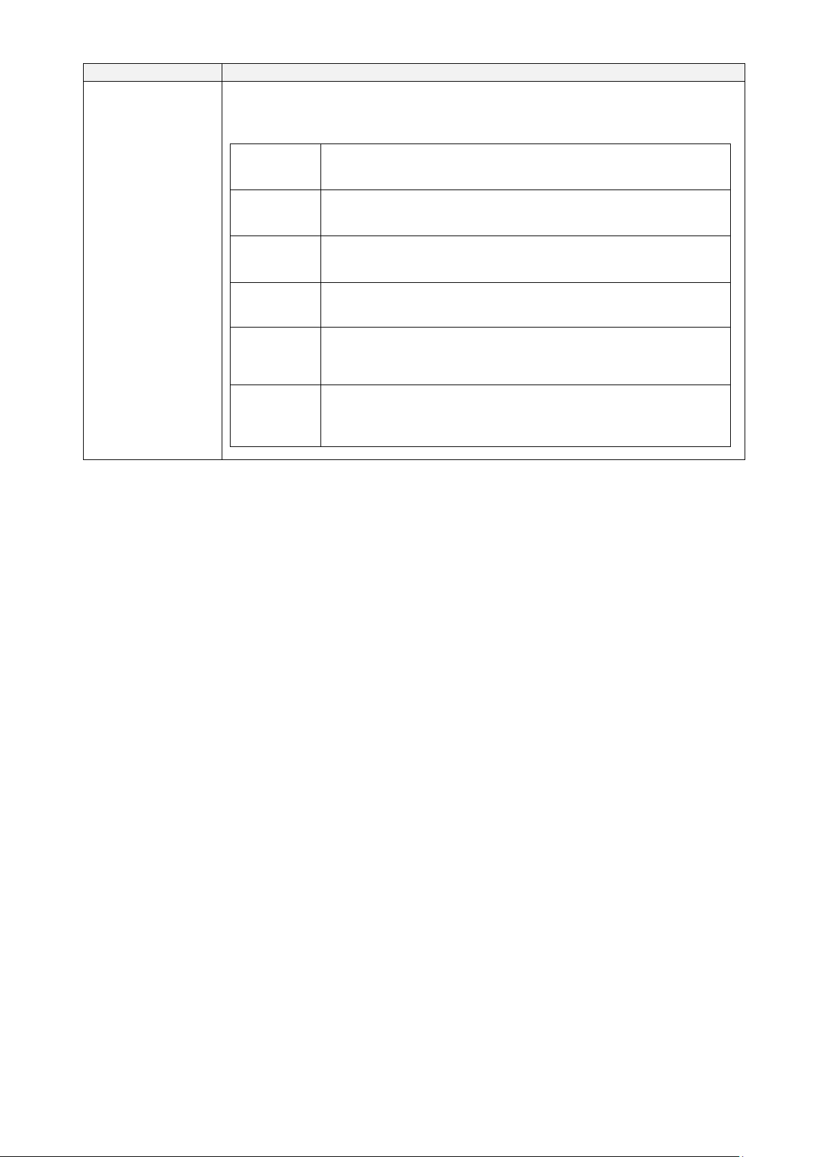
Item
Description
Print Config.
Print the current printer configuration. On the configuration printout, there is
a Print Head test pattern, which is useful for checking if there is dot damage
to the Print Head Heating Element.
For more information, see section 6.1.2
Gap/Black Mark Sensor
Calibration, Self-Test, and Entering Dump Mode.
Dump Mode
Captures the data from the communications port and prints out the data
received by the printer. In the Dump Mode, all characters will be printed in
two columns. The characters in the left column are received from the
printer's system and those in the right column are their hexadecimal
representation. It allows you to verify and debug the program.
For more information, see section 6.1.2
Gap/Black Mark Sensor
Calibration, Self-Test, and Entering Dump Mode.
Note
Dump Mode requires 101.6 mm paper width.
Print Head
Check for any visible dots and the Print Head's temperature.
Display
Check the Touchscreen color state.
Sensor
Check the sensors’ intensity and reading state.
Menu Diagnostic
Print Config.
Dump Mode
Print Head
Display
Sensor
Diag Gap
Diag Black Mark
Diag Ribbon End
Diag Media

73
8. Brother Printer Management Tool (BPM)
The Brother Printer Management Tool (BPM) is an integrated tool that lets you:
Check a printer’s status and settings
Change printer settings
Send additional commands to a printer
Download graphics and fonts
Create a printer bitmap font
Download and update firmware
Configure Wireless LAN (Wi-Fi)
Using this tool, you can also review your printer's status and settings to troubleshoot any
problems.
8.1 Start the BPM
Double-click the BPM icon to start the software.
The BPM's main screen allows you to access the following options:
Printer Configuration
File Manager
Command Tool
RTC Setup
Printer Function
Bitmap Font Manager
For more information, see the Brother Printer Management Tool Quick Start Guide on your
model's Manuals page at support.brother.com
.
Features
Buttons
Interface
Type
Printer
Status
Configuration
Buttons
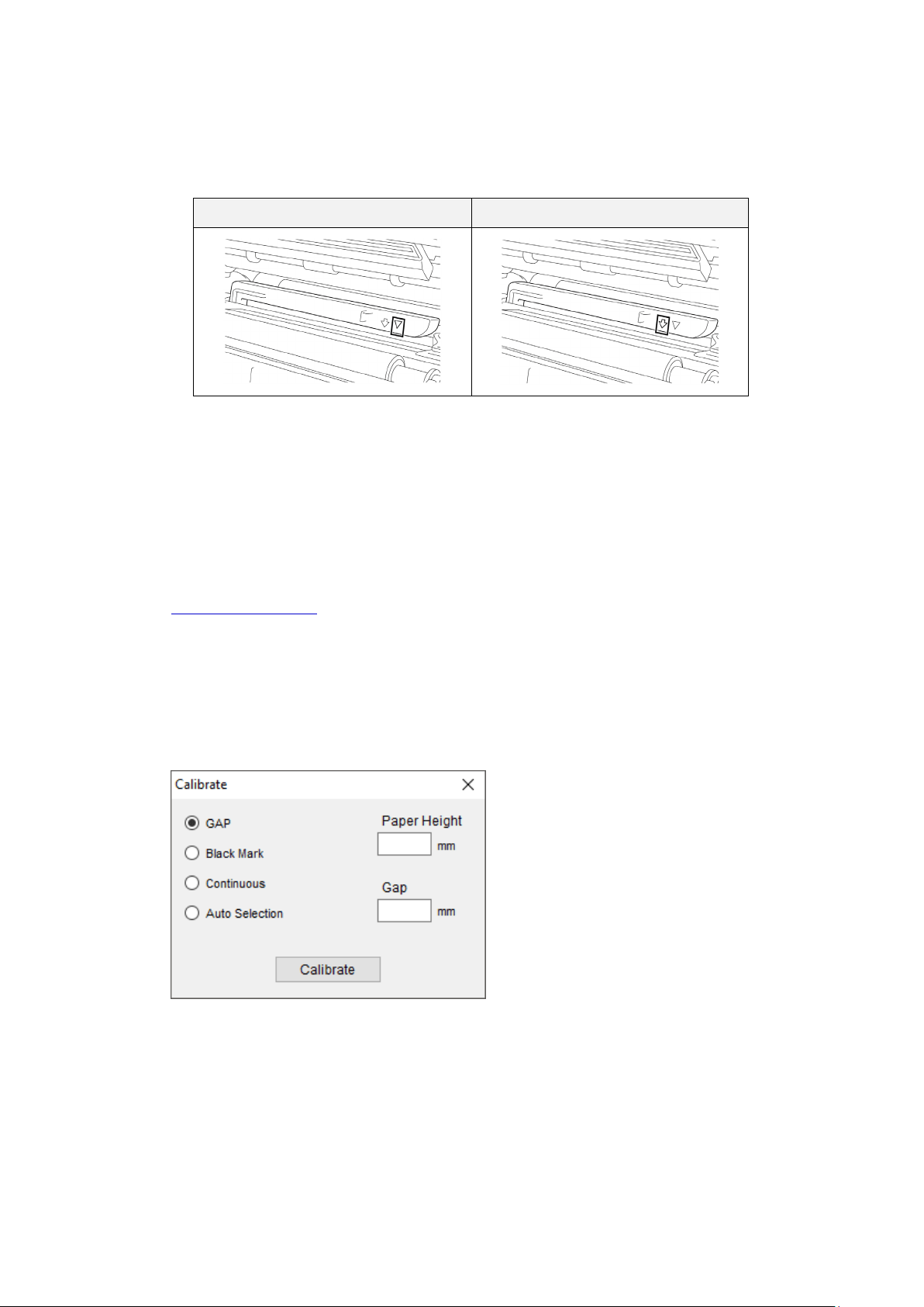
74
8.2 Auto-Calibrating the Media Sensor using the BPM
Use the BPM to set the media sensor type (Gap Sensor or Black Mark Sensor) and calibrate the
selected sensor.
Gap Sensor Black Mark Sensor
The Gap Sensor (transmissive sensor) detects the beginning of the label and the printer feeds
the label to the correct position.
The Black Mark Sensor (reflective sensor) detects the mark and the printer feeds the media to
the correct position.
1. Make sure the media is already installed and the Print Head is closed. (See section
3.4 Load the Media
.)
2. Turn on the printer.
3. Start the BPM.
4. Click the Printer Function button.
5. Click the Calibrate button.
6. Select the sensor media type and click Calibrate.
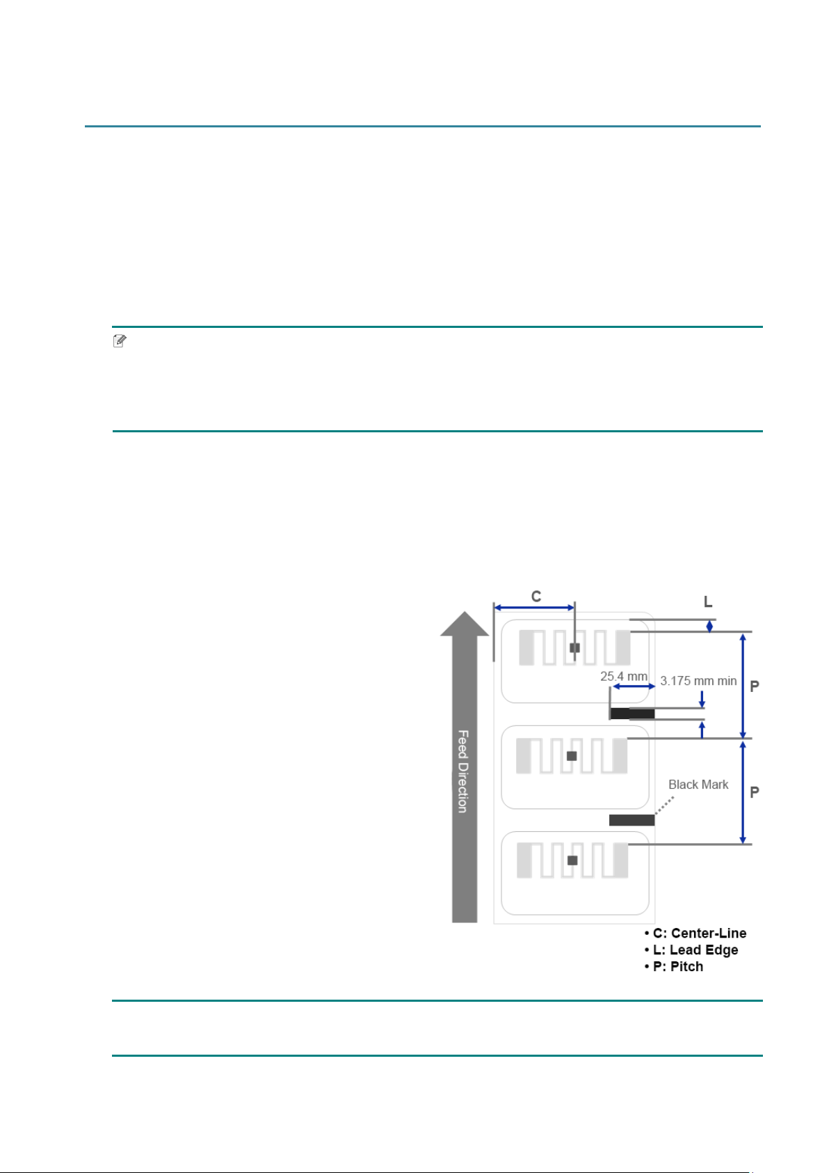
75
9. Setting Up the RFID
(Available for TJ-4021TNR and TJ-4121TNR only)
9.1 Introduction
When printing smart labels that use an EEPROM technology, the printer may need to write and
verify some RFID tags more than once before accepting them. This additional processing may
result in a short pause between each printed label, but is necessary to ensure consistent quality
and reliability.
Note
Static electricity can damage smart labels. Before you handle smart labels, open the printer's
Media Cover and touch an unpainted metal part to discharge any static electricity that may have
built up on your hands.
This printer is equipped with an Auto-Calibration feature, which eliminates the need to specify
exact inlay placement or RFID power settings. The calibration routine is compatible with most
major inlays embedded in typical label sizes and will work with many other inlays as well.
For optimum performance:
Center inlays horizontally across the media
(dimension “C”). Consistent, tag-to-tag
placement of the inlays is more important than
their proximity to the center.
The pitch is the overall distance from inlay to
inlay (dimension “P”). On-pitch tags and tags
with a pitch less than 25.4 mm may require the
printer to back-feed during the encoding and
printing process, thus slowing the throughput of
the printer. To avoid this, this pitch should be
greater than 25.4 mm.
Set the inlay back from the lead edge of the
media (dimension “L”) at the same tag-to-tag
distance. To avoid back-feeding, for labels
longer than 25.4 mm, this distance should be
greater than 12.7 mm.
IMPORTANT
Always test RFID media on your printer before purchasing large quantities of media.
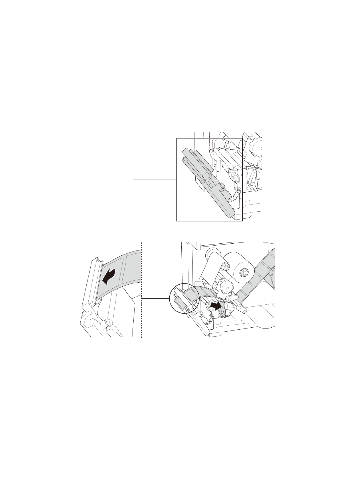
76
9.2 RFID Calibration
The TJ-4021TNR and TJ-4121TNR have a fixed-position RFID antenna mounted at the Media
Output Slot, which supports a wide variety of tag types.
9.2.1 Load the RFID Media
1. Load the RFID media onto the Label Supply Spindle.
2. Open the Print Head and RFID Tear Cover. Thread the media through the Damper, Media
Sensor, and Front Label Guide to install the media.
3. Feed the RFID media through the Tear Cover Slot.
4. Move the media sensor by adjusting the Media Sensor Position Adjustment Knob. Make
sure the position of the Gap or Black Mark Sensor matches the position of the Gap/Black
Mark on the label roll.
5. Adjust the Front Label Guide to fix the media position.
6. Close the Print Head and RFID Tear Cover.
RFID Tear Cover
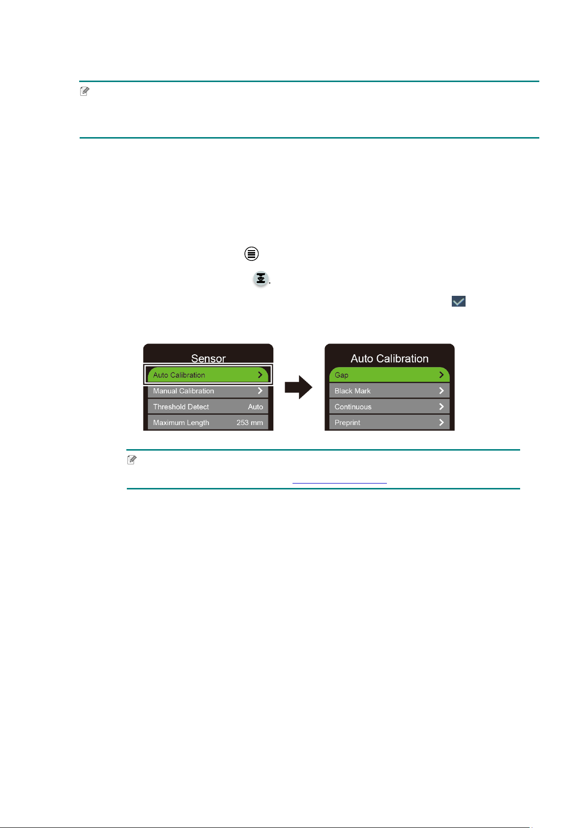
77
9.2.2 RFID Calibration Procedure
Note
For optimal calibration results, perform Media Calibration before RFID Calibration. Make sure
you correctly install both the ribbon and the label roll.
1. Perform Media Auto Calibration:
Using the Touchscreen:
a. Load the RFID media into the printer.
b. (Thermal transfer only) Load the ribbon into the printer.
c. Tap the Menu icon .
d. Tap the Sensor icon .
e. Tap Auto Calibration, select the media type, and then tap the icon to start
the media calibration.
Note
For more information, see section 7.2 Sensor Settings.
Using the BPM:
a. Load the RFID media into the printer.
b. (Thermal transfer only) Load the ribbon into the printer.
c. Connect the USB cable between the computer and the printer.
d. Start the BPM.
e. Select the printer in the list, and then click the Printer Function button.

78
f. Click Calibrate.
g. Click Printer Configuration and make sure the paper width and height in the
FBPL tab are set correctly.
Using the AUTODETECT command:
Note
For more information, see the FBPL Command Reference on your model's Manuals
page at support.brother.com
.
2. Start RFID Calibration.
Using the Touchscreen:
Tap Menu Interface RFID Tag Calibration Do RFID Calibrate,
and then tap the
icon.
Note
For more information, see section 7.3.4 RFID (Radio Frequency Identification)
Settings.
Using the RFIDDETECT command:
Note
For more information, see the FBPL Command Reference on your model's Manuals
page at support.brother.com
.

79
3. Depending on the tag type and tag length, the calibration can take several minutes. At the
end of calibration either a green or red screen appears. The green screen appears when the
calibration is successful and the red one when it is not.
4. If calibration fails, tap the or icon to clear the error. In some cases, it may be due to
an incompatibility between the tag and the reader. After the calibration is complete, tap the
or icon to continue and save the RFID calibration values.
Note
For information, see section 11.3 RFID Error Messages.
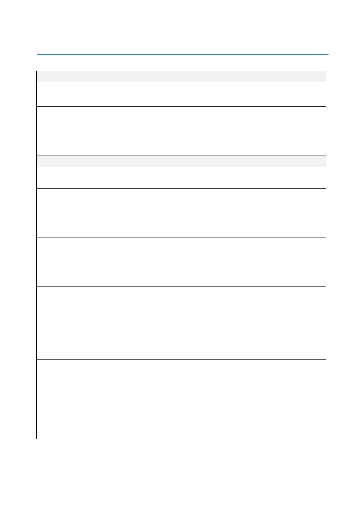
80
10. Product Specifications
Display
Touchscreen
(TJ-4021TN, TJ-4021TNR, TJ-4121TN, TJ-4121TNR)
3.5" Color Touchscreen
LED
(TJ-4005DN, TJ-4010TN, TJ-4020TN, TJ-4120TN)
5 (4 icon indicators, 1 power indicator)
(TJ-4021TN, TJ-4021TNR, TJ-4121TN, TJ-4121TNR)
1 power indicator (3 colors - Green, Red, Amber)
Printing
Print Method
TJ-4005DN: Direct Thermal
Other models: Thermal Transfer and Direct Thermal
Maximum Print Width
(TJ-4005DN, TJ-4010TN, TJ-4020TN, TJ-4021TN, TJ-4021TNR)
107 mm
(TJ-4120TN, TJ-4121TN, TJ-4121TNR)
105.7 mm
Maximum Print Length
(TJ-4005DN, TJ-4010TN, TJ-4020TN, TJ-4021TN, TJ-4021TNR)
25,400 mm
(TJ-4120TN, TJ-4121TN, TJ-4121TNR)
11,430 mm
Maximum Print Speed
(TJ-4005DN, TJ-4010TN)
152.4 mm / second
(TJ-4020TN, TJ-4021TN, TJ-4021TNR)
254 mm / second
(TJ-4120TN, TJ-4121TN, TJ-4121TNR)
177.8 mm / second
Print Speed for Label
Peeler Mode
Up to 3 ips (Except TJ-4021TNR and TJ-4121TNR)
Print Resolution
(TJ-4005DN, TJ-4010TN, TJ-4020TN, TJ-4021TN, TJ-4021TNR)
203 dpi
(TJ-4120TN, TJ-4121TN, TJ-4121TNR)
300 dpi
81
Size
Dimensions
(TJ-4005DN, TJ-4010TN, TJ-4020TN, TJ-4021TN, TJ-4120TN,
TJ-4121TN)
Approximately 248 mm (W) × 436 mm (D) × 274 mm (H)
(TJ-4021TNR, TJ-4121TNR)
Approximately 248 mm (W) × 443 mm (D) × 274 mm (H)
Weight
(TJ-4005DN, TJ-4010TN, TJ-4020TN, TJ-4120TN)
Approximately 9.2 kg
(TJ-4021TN, TJ-4121TN)
Approximately 9.4 kg
(TJ-4021TNR, TJ-4121TNR)
Approximately 9.9 kg
Interface
USB USB Ver. 2.0 (High Speed) (Type B)
Serial RS-232
Wired LAN 10/100 Mbps
USB Host Port
Stand-alone: USB keyboard, USB scanner
Storage: USB flash drive
Wi-Fi (Optional) IEEE 802.11a/b/g/n
Wi-Fi Security
Open, WEP-Open, WPA-PSK/WPA2 (AES and TKIP)
- 802.11i
- WPA2-Enterprise: EAP-FAST, EAP-TTLS, EAP-TLS, PEAPv0
Environment
Temperature
Operation: 0°C - 40°C
Storage: -40°C - 60°C
Humidity
Operation: 25% - 85% (without condensation)
Storage: 10% - 90% (without condensation)
Power Supply
Power Supply
Internal Universal Switching Power Supply
Input: AC 100 V - 240 V, 2.0 A, 50 Hz / 60 Hz
Output: DC 24 V, 3.75 A, 90 W

82
Paper Specification
Media Type
Continuous, die-cut, black mark, fan-fold, notch, RFID tag
(TJ-4021TNR, TJ-4121TNR)
Wound Type Outside wound
Media Width
20 mm - 120 mm (cutter mode: 114 mm max), 25.4 mm - 116 mm
(RFID)
Media Thickness
0.06 mm - 0.28 mm
Up to 1.0 mm for on-metal RFID label (TJ-4021TNR, TJ-4121TNR)
Roll Outside Diameter
(maximum)
203.2 mm
Core Size 25.4 mm - 76.2 mm
Media Sensor Gap (Transmissive), Black mark (Reflective)
Ribbon Specification (Except TJ-4005DN)
Width 450 m long, max. Outer Diameter 81.3 mm
Core Size
25.4 mm (ink coated outside or inside)
(TJ-4021TNR/TJ-4121TNR: ink coated outside)
Ribbon Width 40 mm - 110 mm
RFID Specification (TJ-4021TNR and TJ-4121TNR only)
RF Protocol UHF EPC global Class 1 Gen2 / ISO 18000-6C
Operating Frequency Global (902 MHz - 928 MHz) and EU (866 MHz - 868 MHz)
Minimum Pitch 15.875 mm
Other
Cutter Regular guillotine cutter option (Not User Replaceable)
1 2
Label Peeler Label Peeler option (Not User Replaceable)
1 2
Supported Barcodes
1D barcodes:
Code 11 (USD-8), Code 39, Code 93, Code 128 with subsets A/B/C,
UPC-A, UPC-E, EAN-8, EAN-13, UPC and EAN 2- or 5-digit
extensions, GS1-128 (UCC/EAN-128), MSI, Plessey, POSTNET,
Standard 2-of-5 (IATA), Industrial 2-of-5, Interleaved 2-of-5, ITF-14,
EAN-14, LOGMARS, Codabar (NW-7), Planet, Telepen, Deutsche
Post Identcode, Deutsche Post Leitcode, Datalogic 2-of-5 (China Post)
2D barcodes:
CODABLOCK F, PDF417, Code 49, GS1 DataMatrix, MaxiCode,
QR Code, TLC39, MicroPDF417, GS1 DataBar (RSS), Aztec Code
Printer Control Command
FBPL-EZD (Compatible to FBPL II, EPL II, ZPL II, DPL)
FBPL-EZS (Compatible to FBPL II, EPL II, ZPL II, SBPL)
Built-in Fonts
8 alphanumeric bitmap fonts
Monotype Imaging
®
TrueType font engine with one CG Triumvirate
Bold Condensed scalable font
1
Not compatible with RFID tags.
2
Only authorized Brother Dealers should perform accessory replacements.

83
11. Troubleshooting
11.1 Common Problems
This chapter explains how to resolve typical problems you may encounter when using the printer. If
you have any problems with the printer, first make sure you have performed the following tasks
correctly.
If you still have problems, contact the product manufacturer's customer service or your local dealer.
Problem Possible Cause Solution
The LED Indicator is not lit. The Power Cord is not
correctly connected.
Make sure the printer is correctly
connected to the power outlet (electrical
socket) using the Power Cord.
The Power Switch is off. Turn the printer on.
Memory full
(DRAM/Flash/Card).
The printer's DRAM/Flash/
Card memory is full.
Delete unused files from the DRAM/Flash/
Card memory.
Poor Print Quality.
The ribbon/media is loaded
incorrectly.
Reload the media/ribbon.
(Except TJ-4005DN)
Dust or adhesive has
accumulated on the Print
Head.
Clean the Print Head.
Clean the Platen Roller.
The print density is set
incorrectly.
Adjust the print density and print speed.
The Print Head is damaged.
Run the printer self-test and check the
Print Head test pattern for missing dots.
The ribbon/media is
incompatible.
Install the correct ribbon/media.
(Except TJ-4005DN)
The print head tension is not
set correctly.
Use the Print Head Tension Adjustment
Knob to adjust the print head tension.
(See section 4. Improve Print Quality)
The Release Lever does not lock the Print
Head in place.
Incomplete printing on the left
or right side of label.
The label size is not specified
correctly.
Check if the label size is set up correctly.
Blank labels with gray lines.
The Print Head is dirty. Clean the Print Head.
The Platen Roller is dirty. Clean the Platen Roller. (See section
12. Maintenance
.)
Irregular printing.
The printer is in Hex Dump
Mode.
Turn the printer on and off to skip the
Dump Mode. (See section
6.1.2
Gap/Black Mark Sensor Calibration,
Self-Test, and Entering Dump Mode.)
The printer’s RS-232
communication is not set
correctly.
Make sure the printer's RS-232 settings
are set up correctly. For more information,
see section 7.3.1
Serial Communication
Settings.
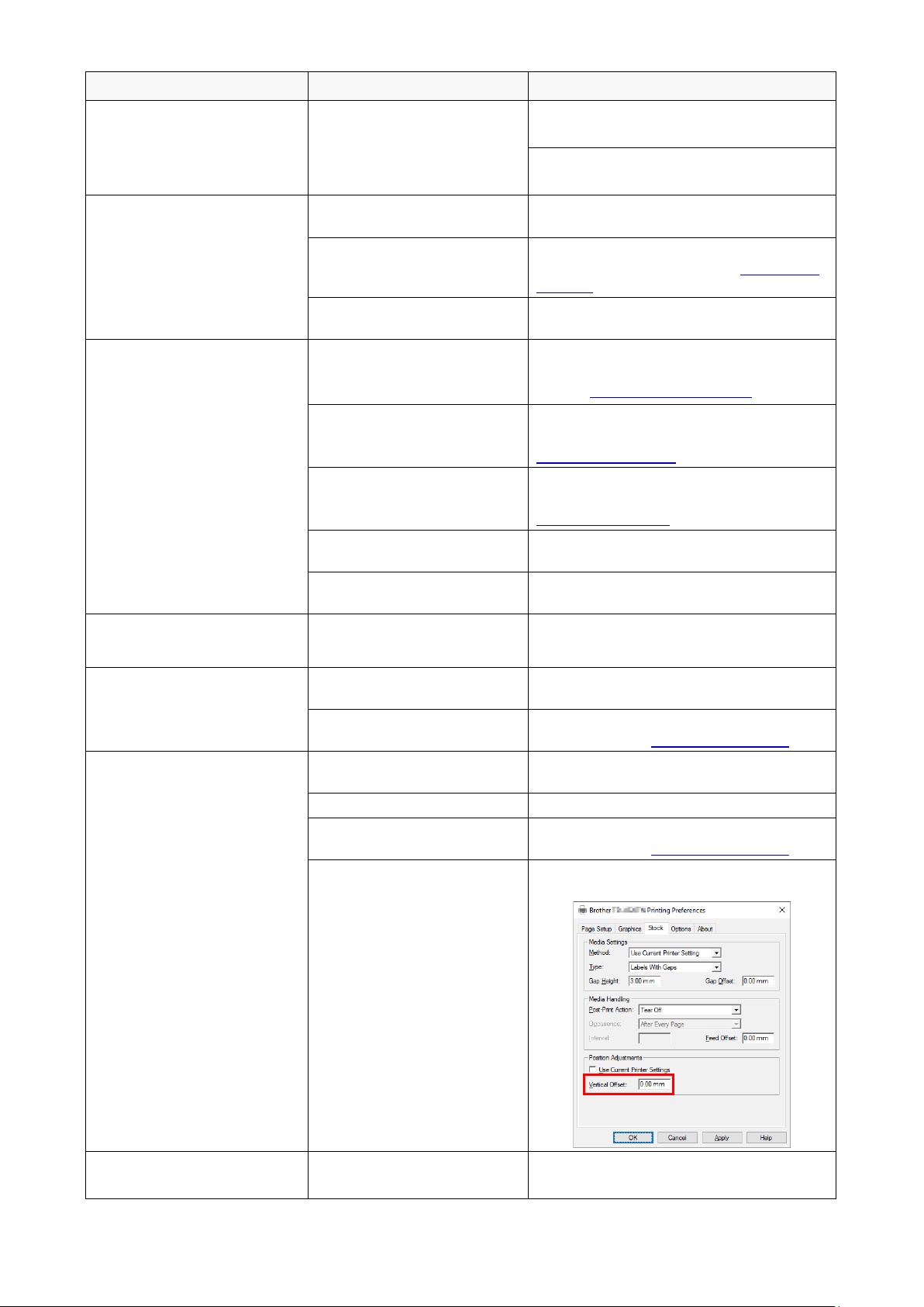
84
Problem Possible Cause Solution
Labels are fed incorrectly
(skewed) when printing.
The media guide does not
touch the edge of the media.
If the label is moving to the right side,
move the Front Label Guide to the left.
If the label is moving to the left side, move
the Front Label Guide to the right.
Labels are skipped when
printing.
The label size is not specified
correctly.
Check if the label size is set up correctly.
The sensor sensitivity is not
set correctly.
Calibrate the Gap Sensor either manually
or automatically (See section 7.2
Sensor
Settings).
The media sensor is dirty. Clean the Gap/Black Mark Sensor using
a compressed air or vacuum.
Ribbon Wrinkles.
(Except TJ-4005DN)
The print head tension is not
set correctly.
Use the Print Head Tension Adjustment
Knob to adjust the print head tension. (See
section 4. Improve Print Quality
)
The ribbon is installed
incorrectly.
Reinstall the ribbon.
To install the ribbon roll, see section
3.2 Load the Ribbon
.
The media is installed
incorrectly.
Reinstall the label roll.
To install the label roll, see section
3.4 Load the Media
.
The print density is not set
correctly.
Adjust the print density to improve the print
quality.
The media is not fed
correctly.
Make sure the Front Label Guide touches
the edge of the Media Guide Tips.
RTC time is incorrect when
rebooting the printer.
The coin battery has dislodged.
The coin battery has finished.
Contact the product manufacturer's
customer service or your local dealer.
The left side printout position
is incorrect.
The label size is set up
incorrectly.
Set the correct label size.
The Shift X setting is
incorrect.
Fine-tune the Shift X setting. For more
information, see 7.1.1 FBPL Settings
.
The printing position of small
labels is incorrect.
The media sensor sensitivity
is not set correctly.
Calibrate the sensor sensitivity again.
The label size is incorrect.
Set the correct label size and gap size.
The Shift Y setting is
incorrect.
Fine-tune the Shift Y setting. For more
information, see 7.1.1 FBPL Settings.
The vertical offset setting in
the driver is incorrect.
If using the BarTender software, set the
Vertical Offset in the driver.
The media wraps around the
platen roller.
The label adhesive is on the
Platen Roller.
Clean the Platen Roller regularly.
85
11.2 Touchscreen Error Messages
TJ-4021TN/TJ-4021TNR/TJ-4121TN/TJ-4121TNR
When an error occurs, the Touchscreen displays the appropriate error message.
Error Message
Possible Cause Solution
Carriage Open
The printer carriage is open.
Close the print carriage.
Not Printing
The serial or USB cable is not
connected correctly.
Reconnect the serial or USB cable.
The wireless device may be
connected incorrectly to the
printer.
Reset the device's wireless settings and set up
the device again.
The serial or USB cable may
be damaged.
Try a new cable.
The port specified in the
Windows driver is not correct.
Specify the correct port.
The Print Head may need
cleaning.
Clean the Print Head.
The Print Head's harness
connector may not be
connected correctly with the
Print Head.
Turn off the printer and plug the Print Head's
harness connector to the Print Head again.
Your custom program may not
contain the necessary
commands.
Make sure that your program contains the
PRINT command at the end of the file and a
CRLF at the end of each command line.
No print on the
label
The ribbon/media is loaded
incorrectly.
Reload the media/ribbon.
Make sure the ink coated ribbon is set in the
correct position.
The ribbon/media is
incompatible.
Install the correct ribbon/media.
The print density is set
incorrectly.
Adjust the print density.
No Ribbon
The ribbon has finished.
Install a new ribbon roll. To install a new ribbon
roll, see section 3.2 Load the Ribbon
.
The ribbon is installed
incorrectly.
Reinstall the ribbon. To install the ribbon roll,
see section 3.2 Load the Ribbon
.
No Paper
The label roll has finished.
Install a new label roll. To install a new label roll,
see section 3.4 Load the Media
.
The label is installed
incorrectly.
Reinstall the label roll. To install the label roll,
see section 3.4 Load the Media
.
The Gap/Black Mark Sensor is
not calibrated.
Calibrate the Gap/Black Mark Sensor.
Paper Jam
The Gap/Black Mark Sensor is
not calibrated.
Calibrate the Gap/Black Mark Sensor.
The label size is not set
correctly.
Set the label size correctly.
A paper jam occurred inside
the printer.
Remove the jammed paper.
Take Label
Peeler Mode
is enabled.
Remove the label.
86
11.3 RFID Error Messages
TJ-4021TNR, TJ-4121TNR
The RFID encoder can detect several errors. When these errors occur, the RFID encoder alerts the
printer and the Touchscreen displays the appropriate error message.
Error Message Possible Cause Solution
RFID Is
Disabled
The RFID function is not
activated.
Select RFID > Control > RFID Active to enable
the RFID function.
Failure
EPC Write Failed
The EPC tag cannot be written
via Diagnostics > Write EPC
with 1s or Write EPC with 2s.
The label could be misaligned. Perform the
Sensor > Auto Calibration procedure to ensure
the label is at top-of-form.
Select RFID > Tag Calibration > Do RFID
Calibrate.
Use smart labels with RFID tags located in the
correct position.
The RFID tag could be defective. Try another tag.
Make sure the application does not send too few
or too many digits to the RFID tag.
RFID Calibrate
Write Tag Failed
Tag calibration cannot be
performed.
The label could be misaligned. Perform the
Sensor > Auto Calibration procedure to ensure
the label is at top-of-form.
Use smart labels with RFID tags located in the
correct position.
The RFID tag could be defective. Try another tag.
RFID
Disabled
The RFID command is sent to
the printer when the RFID
function is disabled.
1. Select RFID > Control > RFID Active to
enable the RFID function.
2. Send RFID commands.
NON-RFID DATA
On RFID Tag
When the “Non-RFID warning”
option is “ON” (RFID > Control
> Non-RFID Warning), the
printer has obtained the
non-RFID data.
Make sure you send RFID commands to the
printer.
INVALID RFID
DATA
The RFID tag data sent does
not match the settings.
Check the tag data of the RFID commands.
INVALID RFID
DATA LEN
The tag length size (the size
parameter of RFID command)
sent does not match the setting.
Check the data length size of the RFID
commands.
RFID TAG
FAILED
The tag cannot be written. The label could be misaligned. Perform the
Sensor > Auto Calibration procedure to ensure
the label is at top-of-form.
Select RFID > Tag Calibration > Do RFID
Calibrate.
Use smart labels with RFID tags located in the
correct position.
The RFID tag could be defective. Try another tag.
Make sure the application does not send too few
or too many digits to the RFID tag.
Check that the RFID commands are correct.
87
Error Message Possible Cause Solution
RFID ERROR
No Tag Found
The tag cannot be read. Make sure the media are smart labels with RFID
tags located in the correct position.
The RFID tag could be defective. Try another tag.
Remove Label
or
No Paper
The label is jammed inside the
machine or the paper size is not
correct.
Remove the label carefully so as not to damage
the printer.
Make sure the media are smart labels that have
RFID tags located in the correct position.
To reduce vibration to the printer, position the
printer so printed labels can fall freely to a lower
surface.
Calibrate the Gap/Black Mark Sensor.
Set the label size correctly.
Note
If you cannot write RFID tags:
Make sure you are using smart labels with RFID tags located in the correct position.
The RFID tag could be defective. Try another tag.
Set the label size correctly, and then calibrate the RFID tag.
Set the sensor sensitivity correctly (using the Touchscreen: Sensor > Gap/Bline Ref Rate).
Check the data length size of the RFID commands.
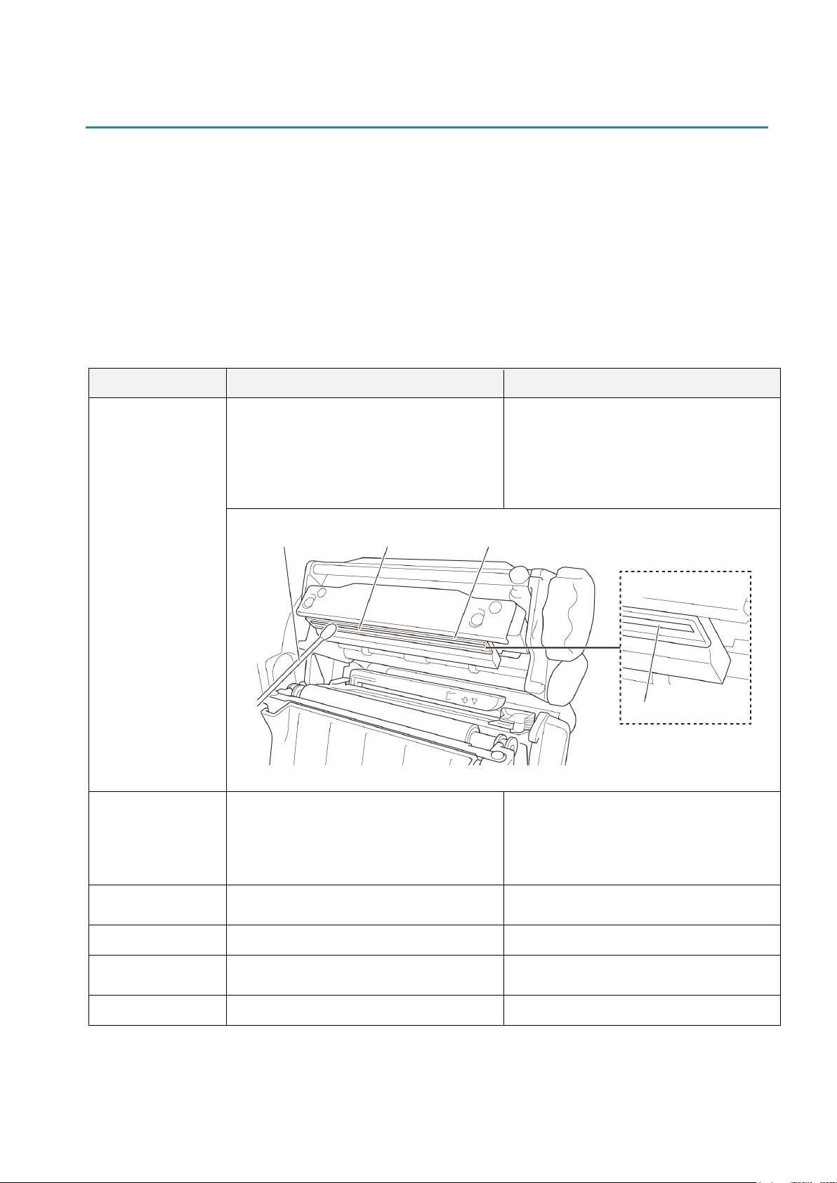
88
12. Maintenance
We recommend cleaning your printer on a regular basis to maintain its correct performance.
Recommended cleaning materials:
• Cotton swab
• Lint-free cloth
• Vacuum / Blower brush
• Compressed air
• Isopropyl alcohol or ethanol
Printer Part Cleaning Method Interval
Print Head
1. Turn the printer off.
2. Allow the Print Head to cool down
for at least one minute.
3. Wipe the Print Head with a cotton
swab dipped in isopropyl alcohol or
ethanol.
Clean the Print Head when changing a
label roll.
Platen Roller
1. Turn the printer off.
2. Rotate the Platen Roller and wipe it
thoroughly with a lint-free cloth or
cotton swab dipped in isopropyl
alcohol or ethanol.
Clean the Platen Roller when changing
a new label roll.
Peel Bar
Wipe with a lint-free cloth dipped in
isopropyl alcohol or ethanol.
As needed.
Sensor
Use compressed air or vacuum. Monthly.
Exterior
Wipe the printer exterior with a lint-free
cloth dipped in water.
As needed.
Interior
Use a brush or vacuum. As needed.
Cotton Swab
Print Head Surface
Print Head Surface
Print Head
Print Head

89
Note
Do not touch the Print Head. If you have touched it, clean it as described above.
Do not use medical alcohol as it may damage the Print Head. Use isopropyl alcohol or
ethanol according to the manufacturer's safety guidelines, as applicable.
To maintain correct performance, we recommend cleaning the Print Head and sensors every
time you install a new ribbon.
IMPORTANT
Securely dispose of any printers, components, and supplies if they are no longer going to be
used. Ensure there is no jammed paper in the printer and destroy the thermal transfer ribbon if it
has retained any visible prints.