
Owner's Manual
ICRRFTSMRWI
17.5 HP
ELECTRIC START
42" MOWER
6 SPEED TRANSAXLE
LAWN TRACTOR
Model No.
917.271734
• Safety
• Assembly
• Operation
• Maintenance
• Repair Parts
CAUTION:
Read and follow all Safety
Rules and Instructions before
operating this equipment.
Foranswers to your questions
about this product,Call:
1-800-659-5917
Sears Craftsman Help Line
5 am - 5 pm, Mon - Sat
Sears, Roebuck and Co., Hoffman Estates, II 60179
Visit our Craftsman website:www.sears.corn/craftsman
WarranT ...............................................2
Safety_tules.........................................3
ProductSpecifications .......................... 6
Assembly .............................................. 8
Operation ............................................ 11
Maintenance Schedule ...................... 17
Maintenance ....................................... 17
Service and Adjustments.................... 21
Storage ............................................... 27
Troubleshooting ................................. 28
Repair Parts ........................................ 32
Parts Ordering ..................... Back Cover
LIMITED 33NOYEAR WARRANTY ON CRAFTSMAN RIDING EQUIPMENT PARTS
For two (2) years from the date of purchase, if this Craftsman Riding Equipment is
maintained, lubricated and tuned up according to the instructionsin the owneCs
manual Sears will repair or replace, free of charge, any partsfound to be defective in
material or workmanship. Warranty service is available free of charge by returnng your
Craftsman riding equipment to your nearest Sears Service Center. In-home warranty
service is available but a trip charge will apply. This warranty applies only white this
productis in the United States.
This Warranty does not cover:
• Expendable items which become worn during normal use, such as blades, spark
plugs, air cleaners, belts and oil filters.
• Tire replacement or repair caused by punctures from outside objects, such as nails,
thorns, stumps, or glass.
• Repairs necessary because of operator abuse, includingbut not limitedto, damage
caused by towing objects beyond the capability of the ridingequipment, impacting
objectsthat bend the frame or crankshaft, or over speeding the engine.
• Repairs necessary because of operator negligence, including but not limited to,
electrical end mechanical damage caused by improper storage, failure to use the
proper grade and amount of engine oil, failure to keep the deck clear of flammable
debris, or the failure to maintain the equipment according to the instructionscon-
tained in the owner's manual.
• Engine (fuel system) cleaning or repairs caused by fuel determined to be contami-
nated or oxidized (stale). In general, fuel should be used within thirty (30) days of its
purchase date.
• Riding equipment used for commercial or rental purposes. A productis "used for
commercial purpose" if is used for any purpose other than single family household
dwellings or in usage where profit is made.
LIMITED 90 DAY WARRANTY ON BA'I-I'ERY
For ninety (90) days from date of purchase, if any battery included with this dding
equipment proves defective in matedal or workmanship and our testing determines the
battery will not hold a charge, Sears will replace the battery at no charge. Warranty
service is available free of charge by returning your Craftsman dding equipment to
your nearest Sears Service Center. In-home warranty service is available but a trip
charge will apply.This warranty applies only while this product is in the United States.
TO LOCATE THE NEAREST SEARS SERVICE CENTER OR TO SCHEDULE IN-HOME
WARRANTY SERVICE, SIMPLY CONTACT SEARS AT 1-800-4-MY-HOME
This Warranty gives you specific legal dghts, and you may also have other dghts which
may varyfrom state to state.
Sears, Roebuck and Co., 13/817WA, Hoffman Estates, IL 60179
2
IMPORTANT: This cutting machine is capable of amputating hands and feet and
throwingob ects. Failure to observe the following safety instructionscould result in
serious injury or death.
I, GENERAL OPERATION
• Read, understand, and follow all
instructionsin the manual and on the
machine before starting.
• Only allow responsible adults, who are
familiar with the instructions,to operate
the machine.
• Clear the area of objects such as rocks,
toys, wire, etc., which could be picked
up and thrown by the blade.
• Be sure the area is clear of other people
before mowing. Stop machine if anyone
enters the area.
• Never carry passengers.
• Do not mow in reverse unless abso-
lutely necessary. Always lock down and
behind before and while backing.
• Be aware of the mower discharge
directionand do not point it at anyone.
Do not operate the mower without either
the entire grass catcher or the guard in
place.
• Slow down before turning.
• Never leave a running machine unat-
tended. Always turn off blades, set
parking brake, stop engine, and remove
keys before dismounting.
• Turn off blades when not mowing.
• Stop engine before removing gross
catcher or unclogging chute.
• Mow only in daylight or good artificial
light.
• Do not operate the machine while under
the influence of alcohol or drugs.
• Watch for traffic when operating near or
crossing roadways.
• Use extra care when loading or unload-
ing the machine into a trailer or truck.
• Data indicatesthat operators, age 60
years and above, are involvedin a large
percentage of riding mower-related
injuries. These operators should
evaluate their abilityto operate the riding
mower safely enough to protectthem-
selvesand others from serious injury.
• Keep machinefree ofgrass, leaves or
other debris build-upwhich can touch
hotexhaust / engine parts and bum. Do
not allowthe mower deck to plow leaves
or other debris whichcan cause build-up
to occur.Clean any oil or fuel
spillage before operatingor storing the
machine. Allow machine tocool before
storage.
3
II. SLOPE OPERATION
Slopes are a major factor related to loss-
of-control and tipover accidents, which
can result in severe injuryor death. All
slopes require extra caution. Ifyou
cannot back up the slope or ifyou feel
uneasy on it, do not mow it.
DO:
• Mow up and down slopes, not across.
• Remove obstacles such as rocks, tree
limbs, etc.
• Watch for holes, ruts, or bumps.
Uneven terrain could overturn the
machine. Ta/I grass can hide obstac/es.
• Use slow speed. Choose a low gear
so that you will nothave to stopor shift
while on the slope.
• Follow the manufacturer's recommen-
dations for wheel weights or counter-
weights to improve stability.
• Use extra care with grass catchers or
other attachments. These can change
the stability ofthe machine.
• Keep all movement on the slopes s/ow
and gradual. Do not make sudden
changes in speed or direction.
• Avoid starting or stopping on a slope. If
tires lose traction, disengage the
blades end proceed slowly straight
down the slope.
DO NOT:
• Do not turn on slopes unlass neces-
sary, and then, turn slowlyand gradu-
ally downhill, if possible.
• Do not mow near drop-offs, ditches, or
embankments. The mower could
suddenly turn over if a wheel is over
the ed.geof a cliffor ditch, or if an edge
caves In.
• Do not mow on wet grass. Reduced
traction could cause sliding.
• Do not try to stabilize the machine by
putting yourfoot on the ground.
• Do not use grass catcher on steep
slopes.
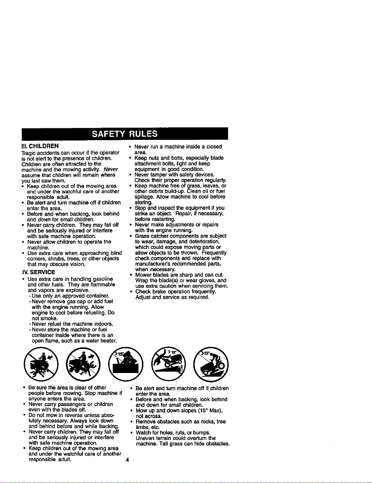
III,CHILDREN
Tragicaccidentscanoccuriftheoperator
isnotalerttothepresenceofchildren.
Childrenare often attracted to the
machine and the mowing activity. Never
assume that children will remain where
you last saw them.
• Keep children out of the mowing area
and under the watchful care of another
responsible adult.
• Be alert and turn machine off if children
enter the area.
• Before and when backing, look behind
and down for small children.
• Never carrychildren. They may fall off
and be seriously injured or interfere
with safe machine operation.
• Never allow children to operate the
machine.
• Use extra care when approaching blind
corners, shrubs, trees, or other objects
that may obscure vision.
IV. SERVICE
• Use extra care in handling gasoline
and other fuels. They are flammable
and vapors are explosive.
-Use only an approved container.
-Never remove gas cap or add fuel
with the engine running. Allow
engine to cool before refueling. Do
notsmoke.
-Never refuel the machine indoors.
- Never store the machine or fuel
container inside where there is an
open flame, such as a water heater.
• Never run a machine inside a closed
area,
• Keep nuts and belts, espociailyblade
attachment belts, tight and keep
equipment in good condition.
• Never tamper with safety devices.
Check their proper operation regularly.
• Keep machine free of grass, leaves, or
other debris build-up. Clean oilor fuel
spillage. Allow machine to cool before
stodng.
• Stop and inspect the equipment if you
strike an object. Repair, if necessary,
before restarting.
• Never make adjustments or repairs
with the engine running.
• Grass catcher components are subject
to wear, damage, and deterioration,
which could expose moving parts or
allow objects to be thrown. Frequently
check components and replace with
manufacturer's recommended parts,
when necessary.
• Mower blades are sharp and can cut.
Wrap the blade(s) or wear gloves, and
use extra caution when servicing them.
• Check brake operation frequently.
Adjust and service as required.
• Be sure the area is clear of other
people before mowing. Stop machine if
anyone enters the area.
• Never carry passengers or children
even with the blades off.
• Do not mow in reverse unless abso-
lutely necessary. Always look down
and behind before and while backing.
• Never carry children. They may fall off
and be seriously injured or interfere
with safe machine operation.
• Keep children out of the mowing area
and under the watchful care of another
responsible adult.
• Be alert and rum machine off if children
enter the area.
• Before and when backing, look behind
end down for smallchildren.
• Mow up and down slopes (15° Max),
notacross.
• Remove obstacles such as rocks,tree
limbs, etc.
• Watch for holes, ruts, or bumps.
Uneven terrain could overturn the
machine. Tall grass can hide obstacles.
4
• Use slow speed. Choose a low gear so
that you will not have to stop or shift
while on the slope.
• Avoid startingor stopping on a slope. If
tires lose traction, disengage the
blades and proceed slowly straight
down the slope.
• If machine stops while going uphill,
disengage blades, shift into reverse
and back down slowly.
• Do not turnon slopes unless neces-
sary, and then, turn slowly end gradu-
ally dOwnhill,if possible.
_-Look for this symbol to point out
importantsafety precautions. It means
CAUTIONIn BECOME ALERTlll YOUR
SAFETY IS INVOLVED.
A(_ CAUTION: In order to prevent
accidental starting when setting up,
transporting, adjusting or making repairs,
always disconnect spark plug wire and
place wire where it cannot contact spark
plug.
_, CAUTION: Do not coast down a hill
in neutral, you may lose control of the
tractor.
CAUTION: Tow onlythe attachments
that are recommended by and comply
with specifications o! the manufacturer of
your tractor. Use common sense when
towing. Operate only at the lowest
possiblespeed when on a slope. Too
heavy of a load, while on a slope, is
dangerous. Tires can lose traction with
the ground and cause you to lose control
ofyour tractor.
_.WARNING: Engine exhaust, some of
its constituents, and certain vehicle
components contain or emit chemicals
known to the Slate of California to cause
cancer and birth defects or other repro-
ductive harm.
_WARNING: Battery posts, terminals
and related accessories contain lead and
lead compounds, chemicals known to the
State of California to cause cancer and
birth defects or other mpreductive harm.
Wash hands after handling.
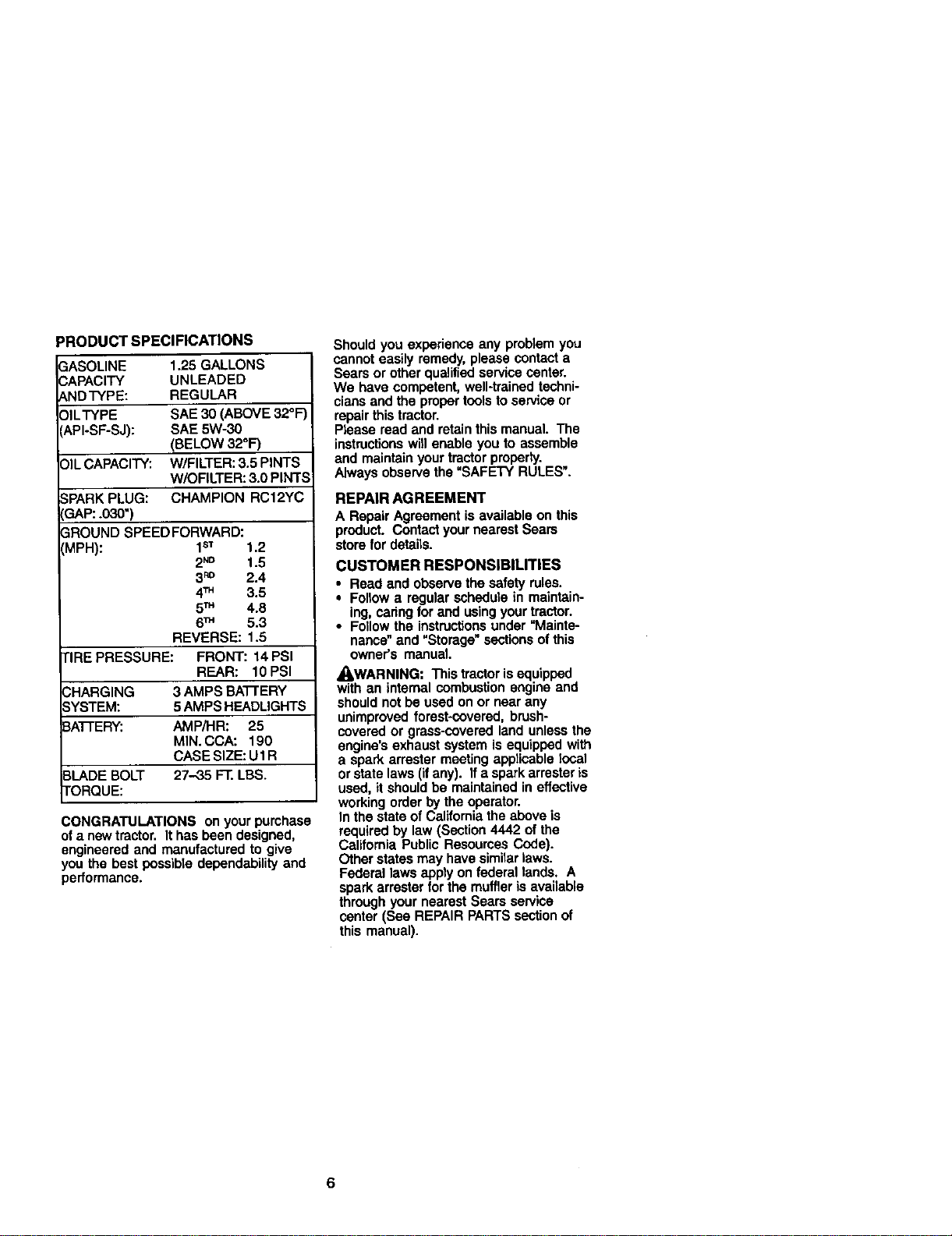
PRODUCTSPECIFICATIONS
GASOLINE 1.25GALLONS
CAPACITY UNLEADED
ANDTYPE: REGULAR
OILTYPE SAE30(ABOVE32°F
API-SF-SJ): SAE5W-30
(BELOW32°F)
_)ILCAPACITY: W/FILTER: 3.5 PINTS
W/OFILTER: 3.0 PINTS
._PARKPLUG: CHAMPION RC12YC
IGAP:.030")
3ROUND SPEEDFORWARD:
'MPH): 1sT 1.2
2N° 1.5
3_° 2.4
4TM 3.5
5TM 4.8
6TM 5.3
REVERSE: 1.5
TIRE PRESSURE: FRONT: 14 PSI
REAR: 10PSI
CHARGING 3 AMPS BA']-rERY
SYSTEM: 5AMPS HEADLIGHTS
BATTERY: AMP,'HR: 25
MIN. CCA: 190
CASE SIZE: U1 R
BLADE BOLT 27-35 FT. LBS.
TORQUE:
CONGRATULATIONS on your purchase
ofa newtractor. It has been designed,
engineered and manufactured to give
you the best possible dependability and
performance.
Should you experienca any problem you
cannot easily remedy, please contact a
Sears or other qualilied service center.
We have competent, well-trained techni-
cians and the proper toolsto service or
repair this tractor.
Please read and retainthis manual. The
instructionswill enable youto assemble
and maintain your tractor properly.
Always observe the "SAFETY RULES".
REPAIR AGREEMENT
A Repair Agreement is available on this
product. Contact your nearest Sears
store for details.
CUSTOMER RESPONSIBILITIES
• Read and observe the safety rules.
• Follow a regular schedule in maintain-
ing, caring for and using your tractor.
• Followthe instru_ons under "Mainte-
nance" and "Storage" sectionsof this
owner's manual.
/kWARNING: This tractor is equipped
with an internal combustion engine and
should not be used on or near any
unimproved forest-covered, brush-
covered or grass-covered land unless the
engine's exhaust system is equipped with
a spark arrester meeting applicable tocal
orstate laws (if any). If a spark arrester is
used, it should be maintained in effective
working order by the operator.
In the state of California the above is
required by law (Section 4442 of the
California Public Resources Cede).
Other states may have similarlaws.
Federal laws apply on federal lands. A
spark arrester for the muffler is available
through your nearest Sears service
center (See REPAIR PARTS section of
this manual).
6
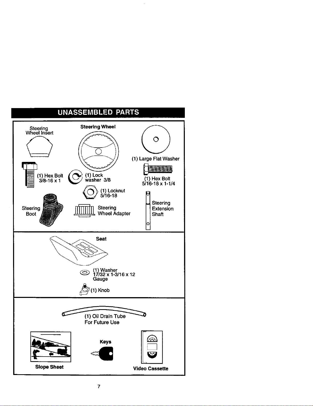
Steering
WheelInsert
(1)HexBolt
3/8-16x I
Boot
SteerlngWheel
(1) Lockwasher 3/8
(1) Locknut
5/16-18
,_= Steering
Wheel Adapter
(1) Washer
17/32 x 1-3/16 x 12
Gauge
_(1) Knob
(1) Large Flat Washer
(1) Hex Bolt
5/16-18 x 1-1/4
I teering
E_ension
Shaft
For Future Use
Slope Sheet
Keys
Video Cassette
Your newtractor has been assembled at the factorywith exception of those parts left
unassembled for shipping purposes. To ensure safe and proper operation of your
tractor all parts and hardware.you assemble must be tightened securely. Use the
correct tools as necessary to insure proper tightness.
TOOLS REQUIRED FOR ASSEMBLY
A socket wrench set will make assembly
easier. Standard wrench sizes you need
are listed below.
(1) 9/16"wrench (1) Pliers
(2) 1/2"wrench (1) Utility knife
(1) Tire pressure gauge
When right or left hand is mentioned in
this manual, it means, from your pointof
view,when you are in the operating
position (seated behind the steering
wheel).
TO REMOVETRACTOR FROM
CARTON
UNPACK CARTON
1. Remove all accessible loose parts
and parts cartons from carton.
2. Cut, from top to bottom, along lines on
all fourcorners of carton, and lay
panels flat.
3. Check for any additional loose parts
or cartons and remove.
7. Snap steering wheel insert intocenter
of steering wheel.
8, Remove protective materials from
tractor hood and grill.
IMPORTANT: Check for and remove any
staples in skidthat may puncture tires
where tractor isto roll oftskid.
3/8 HexBolt
_--_ Lock Washer
_'_-._ LargeRat
_ Washer
o
BEFORE REMOVINGTRACTOR
FROM SKID
A'n'ACH STEERINGWHEEL
ASSEMBLE EXTENSION SHAFT AND
BOOT
1. Slide extension shaft onto lower
steering shaft. Align mounting holes
in extension and lower shafts and
install5/16 hex bolt and Iocknut.
Tighten securely.
IMPORTANT: Tighten bolt and nut
securelyto 18-22 ft. Ibstorque.
2. Piece tabs ofsteering boot over tab
slotsin dash and push down to
secure.
INSTALL STEERING WHEEL
3. Position trontwheels of the tractor so
they are pointing straightforward.
4. Remove steering wheel adaptor from
steering wheel and slide adapter onto
steering shaft extension.
5. Position steering wheel so cross bars
are horizontal (left to right) and slide
inside boot and onto adapter.
6. Assemble large flat washer, 3/8 lock
washer, 3/8 hex bolt and tighten
securely.
5/16 Locknut
Slots
HOWTO SET UPYOURTRACTOR
CHECK BATI'ERY
1. Lift seat pan to raisedposition and
open battery box door.
NOTE: It this batteryis put intoservice
after month and year indicated on label
(label located between terminals) charge
battery forminimum of one hour at 6-10
amps. (See "BA'I-rERY" in Maintenance
section of this manual for charging
instructions).
Label
Battery
Door
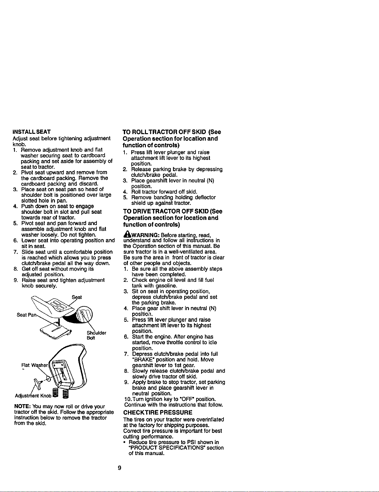
INSTALL SEAT
Adjust seat before tightening adjustment
knob.
1. Remove adjustment knob and flat
washer secunng seat to cardboard
packing and set aside for assembly of
seat totractor.
2. Pivotseat upward and remove from
the cardboard packing. Remove the
cardboard packing and discard.
3. Place seat on seat pan so head of
shoulder bolt is positioned over large
slotted hole in pan.
4. Push down on seat to engage
shoulder bolt in slot and pull seat
towards rear of tractor.
5. Pivot seat and pan forward and
assemble adjustment knob and flat
washer loosely. Do not tighten.
6. Lower seat intooperating position and
sit inseat.
7. Slide seat until a comfortable position
is reached which allows you to press
clutch/brake pedal all the way down.
8. Get off seat withoutmoving its
adjusted position.
9, Raise seat and tighten adjustment
knob securely.
SeatPan_ulder
°u.Z2s
NOTE: You may now rollor drive your
tractor offthe skid. Follow the appropriate
instructionbelow to remove the tractor
from the skid.
TO ROLLTRACTOR OFF SKID (See
Operation section for location and
function of controls)
1. Press lift lever plunger and raise
attachment liftlever to its highest
position.
2. Release parking brake by depressing
clutch/brake pedal.
3. Place gearshift lever in neutral (N)
position.
4. Roll tractor forward off skid.
5. Remove banding holding deflector
shield up against tractor.
TO DRIVETRACTOR OFF SKID (See
Operation section for location and
function of controls)
_WARNING: Before starting, read,
understand and follow all instructionsin
the Operation section of this manual. Be
sure tractor is in a well-ventilated area.
Be sure the area in front of tractor is clear
of other people and objects.
1. Be sure all the above assembly steps
have been completed.
2. Check engine oil level and fill fuel
tank with gasoline.
3. Sit on seat in operating position,
depress clutch/brake pedal and set
the parking brake.
4. Place gear shift lever in neutral (N)
position.
5. Press lift lever plunger and raise
attachment lift lever to its highest
position.
6. Start the engine. After engine has
started, move throttle controlto idle
position.
7. Depress clutch'brake pedal into full
"BRAKE" position and hold. Move
gearshift lever to 1st gear.
8. Slowly release clutch/brake pedal and
slowly drive tractor oft skid.
9. Apply brake to stop tractor, set parking
brake and place gearshift lever in
neutral position.
10.Turn ignition key to "OFF" position.
Continue with the instructions that follow.
CHECKTIRE PRESSURE
The tires on your tractorwere ovednflated
at the factory for shipping purposes.
Correct tire pressure is importantfor best
cutting performance.
• Reduce tire pressure to PSI shown in
"PRODUCT SPECIFICATIONS" section
of this manual.
CHECKDECKLEVELNESS
Forbestcuttingresults,mowerhousing
shouldbepropedyleveled.See"TO
LEVEL MOWER HOUSING" in the
Service and Adjustments section of this
manual.
CHECK FOR PROPER POSITION OF
ALL BELTS
See the figures that are shown for
replacing motion and mower blade drive
belts in the Service and Adjustments
sectionof this manual. Verify that the
belts are routed correctly.
CHECK BRAKE SYSTEM
After you learn how to operate your
tractor,check to see that the brake is
properly adjusted. See "TO ADJUST
BRAKE" in the Service and Adjustments
section of this manual.
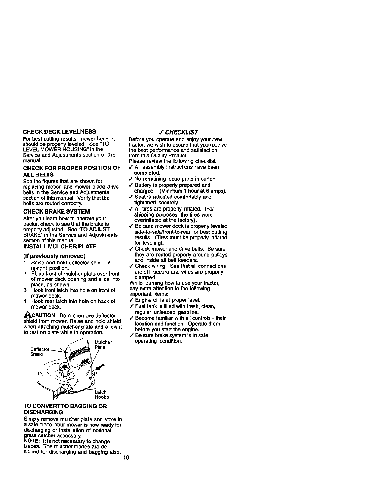
INSTALL MULCHER PLATE
(If previously removed)
1. Raise and hold deflector shield in
upright position.
2. Place front of mulcher plate over front
of mower dock opening and slide into
place, as shown.
3. Hook front latch into hole on front of
mower dock.
4. Hook roar latch into hole on back of
mower dock,
_.CAUTION: Do not remove deflector
shield from mower. Raise and hold shield
when attaching mulcber plate and allow it
to rest on plate while in operation.
Mulcher
Plate
Shield
/ CHECKLIST
Before you operate and enjoy your new
tractor, we wish to assure thatyou receive
the best performance and satisfaction
from this Quality Product.
Please review the following checklist:
/ All assembly instructionshave been
completed.
/ No remaining loose parts in carton.
,/Battery is properly prepared and
charged. (Minimum 1 hour at 6 amps).
/ Seat is adjusted comfortably and
tightened securely.
,/All tires are properly inflated. (For
shipping purposes, the tires were
ovednflated at the factory).
/ Be sure mower dock is properly leveled
side-to-sideifront-to-rear for best cutting
results. (Tires must be properly inflated
for leveling).
,/Chock mower and dnve belts. Be sure
they are routed properly around pulleys
and inside all belt keepers.
,/Chock widng. See that all connections
are stillsecure and wires are properly
clamped.
While learning how to use your tractor,
pay extra attention to the following
important items:
,/Engine oil is at proper level.
,/Fuel tank is filled with fresh, clean,
regular unleaded gasoline.
#" Become familiar with all controls - their
location and function. Operate them
before you start the engine.
/ Be sure brake system is in safe
operating condition.
Latch
Hooks
TO CONVERTTO BAGGING OR
DISCHARGING
Simply remove mulcher plate and store in
a safe place. Your mower is now ready for
discharging or installation of optional
grass catcher accessory.
NOTE: It is not necessary to change
blades. The mulcher blades are de-
signed for discharging and bagging also.
10
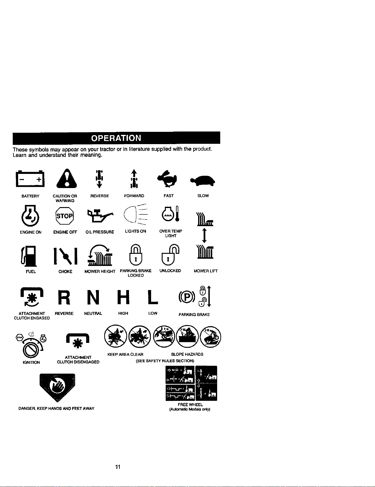
Thesesymbolsmayappearonyourtractororinliteraturesupptiedwiththeproduct.
Learnendunderstandtheirmeaning.
BATI"ERY CAUTION OR REVERSE FORWARD FAST SLOW
WARNING
ENGINE ON ENGINE OFF OIL PRESSURE LIGHTS ON OVER ]_MP t
LIGHT
FUEL CHOKE MOWER HEIGHT PARKING BRAKE UNLOCKED
LOCKED
MOWER LIFT
r_'_ R N H L
ATTACHMENT REVERSE NEUTRAL HIGH LOW
CLUTCH ENGAGED
®3]
PARKING BRAKE
KEEP AREA CLEAR SLOPE HAZARDS
ATTACHMENT
IGNITION CLUTCH DISENGAGED (SEE SAFETY RULES SECTION)
DANGER, KEEP HANDS AND FEET AWAY
FREEWHEEL
(AutomaticUodets only)
11
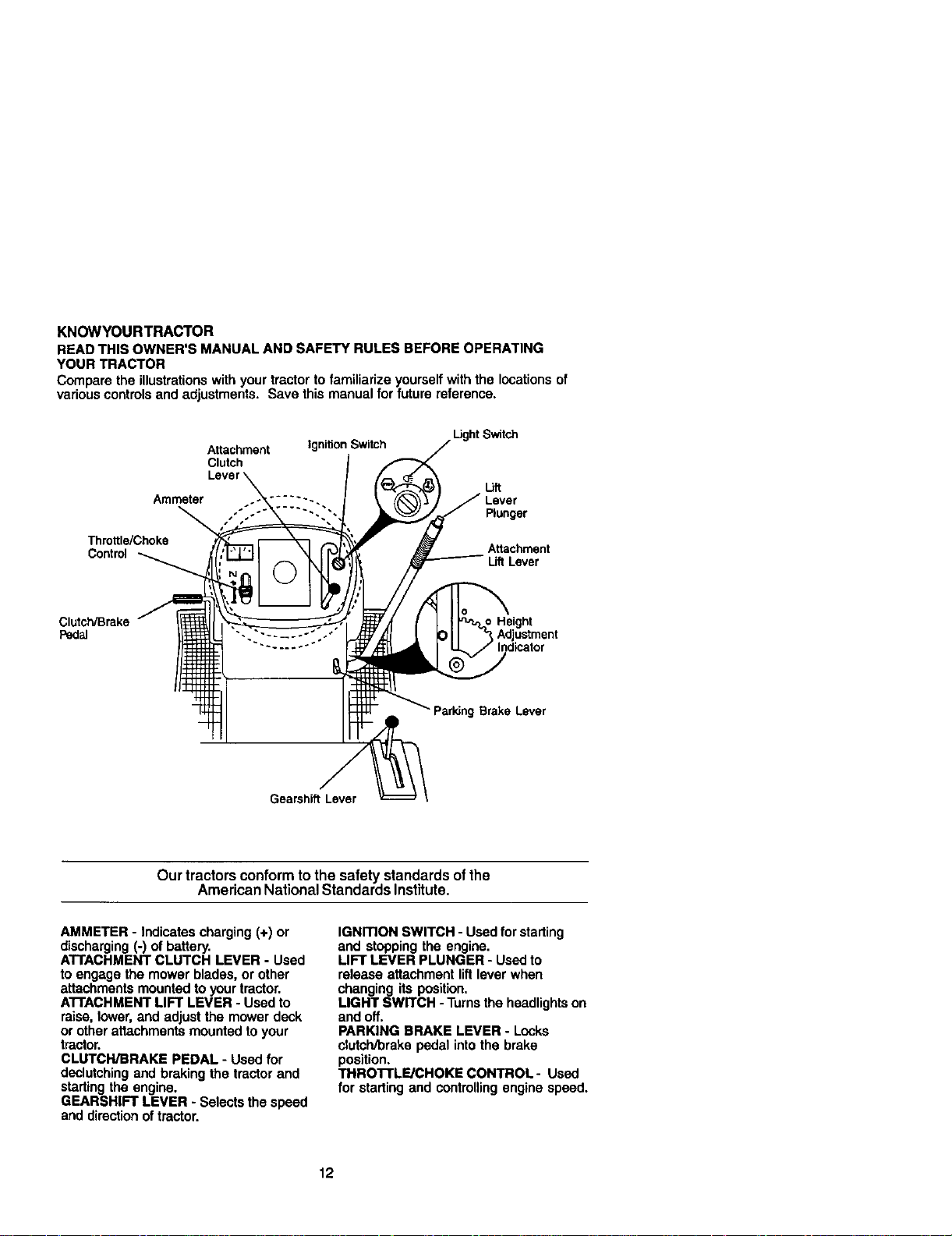
KNOWYOURTRACTOR
READ THIS OWNER'S MANUAL AND SAFETY RULES BEFORE OPERATING
YOUR TRACTOR
Compare the illustrationswith your tractor to familiarize yourself with the locationsof
variouscontrolsand adjustments. Save this manual for future reference.
Attachment Ignition Switch
Clutch
.Ught Switch
lift
Ammeter ..... "-. Lever
..... -. ""- Plunger
Throttle/Choke Attachment
Control Lift Lever
Clutch/Brake _Height
Pedal
parkJng Brake Lever
Gearshift Lever
Our tractorsconform tothe safety standardsofthe
American NationalStandards Institute,
AMMETER - Indicates charging (+) or
discharging (-) of battery.
ATTACHMENT CLUTCH LEVER - Used
to engage the mower blades, or other
attachments mounted to your tractor.
ATTACHMENT LIFT LEVER - Used to
raise, lower, and adjust the mower deck
or other attachments mounted to your
tractor.
CLUTCH/BRAKE PEDAL - Used for
declutching and braking the tractor and
starting the engine.
GEARSHIFT LEVER - Selects the speed
and directionoftractor.
IGNITION SWITCH - Used forstarting
and stopping the engine.
LIFT LEVER PLUNGER - Usedto
release attachment lift lever when
changing its position.
LIGHT SWITCH - Turns the headlightson
and off.
PARKING BRAKE LEVER - Locks
clutch/brake pedal intothe brake
position.
THROTTLE/CHOKE CONTROL- Used
for starting and controlling engine speed.
12
The operation of any tractor can result in foreign ob ects thrown into
the eyes, which can result in severe eye damage. Always wear safety
glasses or eye shieldswhile operating your tractor or performing any
ad ustments or repairs. We recommend a wide vision safety mask over
spectac es or standard safety g asses.
HOWTO USEYOURTRACTOR
TO SET PARKING BRAKE
Your tractoris equipped with an operator
presence sensing switch, When engine
is running, any attempt by the operator to
leave the seat without firstsetting the
parking brake will shut off the engine.
1. Depress clutch/brake pedal into full
=SRAKE" position and hold.
2, Place parking brake lever in =EN-
GAGED" position and release
preasum from clutch/brake pedal.
Pedal should remain in "BRAKE"
position, Make sure parking brake will
hold tractor secure.
Attachment Clutch Lever
=Engaged"_ _ IgnitionKey
Posit;on J "Disengaged"
:" / Position
Co_, --/_ / ParkingBrake
/'Engaged"
Clutch/ "-_.:\ "_"_ :- Position
BrakePedalr-_, ,"---"- =._
Position Position
STOPPING
MOWER BLADES -
• TO stop mower blades,move attach-
ment clutchlever to "DISENGAGED"
position.
GROUND DRIVE -
• To stop ground drive, depress clutch/
brake pedal intofull "BRAKE" position.
• Move gearshift leverto neutral (N)
position.
ENGINE-
• Move throttle control to slow position.
NOTE: Failure to move throttlecontrolto
slow position and allowing engine to idle
before stopping may cause engine to
"backfire'.
• Turn ignition key to "OFF"position and
remove key. Always remove kay when
leaving tractor to prevent unauthorized
use.
• Never use choke to stop engine.
IMPORTANT: Leaving the ignition switch
in any positionother than "OFF" wilt
cause the batteryto be discharged,
(dead).
NOTE: Under certain conditionswhen
tractor is standing idle with the engine
running, hot engine exhaust gases may
cause =browning• of grass. To eliminate
this possibility,always stop engine when
stoppingtractor on grass areas.
,_CAUTION: Always stoptractor
completely, as described above, before
leaving the operator's position;to empty
grass catcher, etc.
TO USETHROTTLE CONTROL
Always operate engine at full throttle.
• Operating engine at less than full
throttle reduces the battery charging
rate.
• Full throttle offers the best bagging
and mower performance.
TO MOVE FORWARD AND
BACKWARD
The direction and speed of movement is
controlled by the gearshift lever.
1. Start tractor with clutch/brake pedal
depressed and gearshift lever in
neutral (N) position.
2. Move gearshift lever to desired
position.
3. Slowly release clutch/brake pedal to
start movement.
IMPORTANT: Bringtractor to a complete
stop before shiftingor changing gears.
Failure to do so will shorten the useful life
of your transaxle.
TO ADJUST MOWER CU'I'rlNG HEIGHT
The position of the attachment liftlever
determines the cutting height.
• Grasp liftlever.
• Press plunger with thumb and move
lever to desired position.
The cutting height range is approxi-
mately 1-1/2 to 4". The heightsare
measured from the groundto the blade
tip with the engine not running. These
heights are approximate and may vary
depending upon soil conditions, height of
grass and types of grass being mowed.
13
• The average lawn should be cut to
approximately 2-1/2 inches during the
cool season and to over 3 inches
during hot months. For healthier and
better Looking lawns, mow often and
after moderate growth.
• For bestcutting performance, grass
over 6 inches in height should be
mowedtwice. Make the first cut
relatively high;the second to desired
height.
TO ADJUST GAUGE WHEELS
Gauge wheels are properly adjusted
when they are slightly off the ground
when mower is at the desired cutting
height in operating position. Gauge
wheels then keep the deck in proper
positionto help prevent scalping in most
terrain conditions.
NOTE: Adjust gauge wheels with tractor
on a fiat level surface.
1. Adjust mower to desired cutting height
(See %0 ADJUST MOWER CUTTING
HEIGHT" inthe Operation section of
this manual).
2. With mower in desired height of cut
position, gauge wheels should be
assembled so they ere slightly off the
ground, install gauge wheel in
appropriate hole with shoulder bolt, 3/
8 washer, and 3/8-16 Iocknut and
tighten securely.
3. Repeat for opposite side Installing
gauge wheel in same adjustment
hole.
Gauge
Wheol
Bracket
3_-16
Locknut
Shoulder Bolt
Gauga Wheel
TO OPERATE MOWER
Yourtractor is equipped with an operator
presence sensing switch. Any attempt by
the operator to leave the seat with the
engine runningand the attachment clutch
engaged will shut off the engine.
1. Select desired height of cut.
2. Start mower blades by engaging
attachment clutch control.
TO STOP MOWER BLADES -
disengage attachment clutch control.
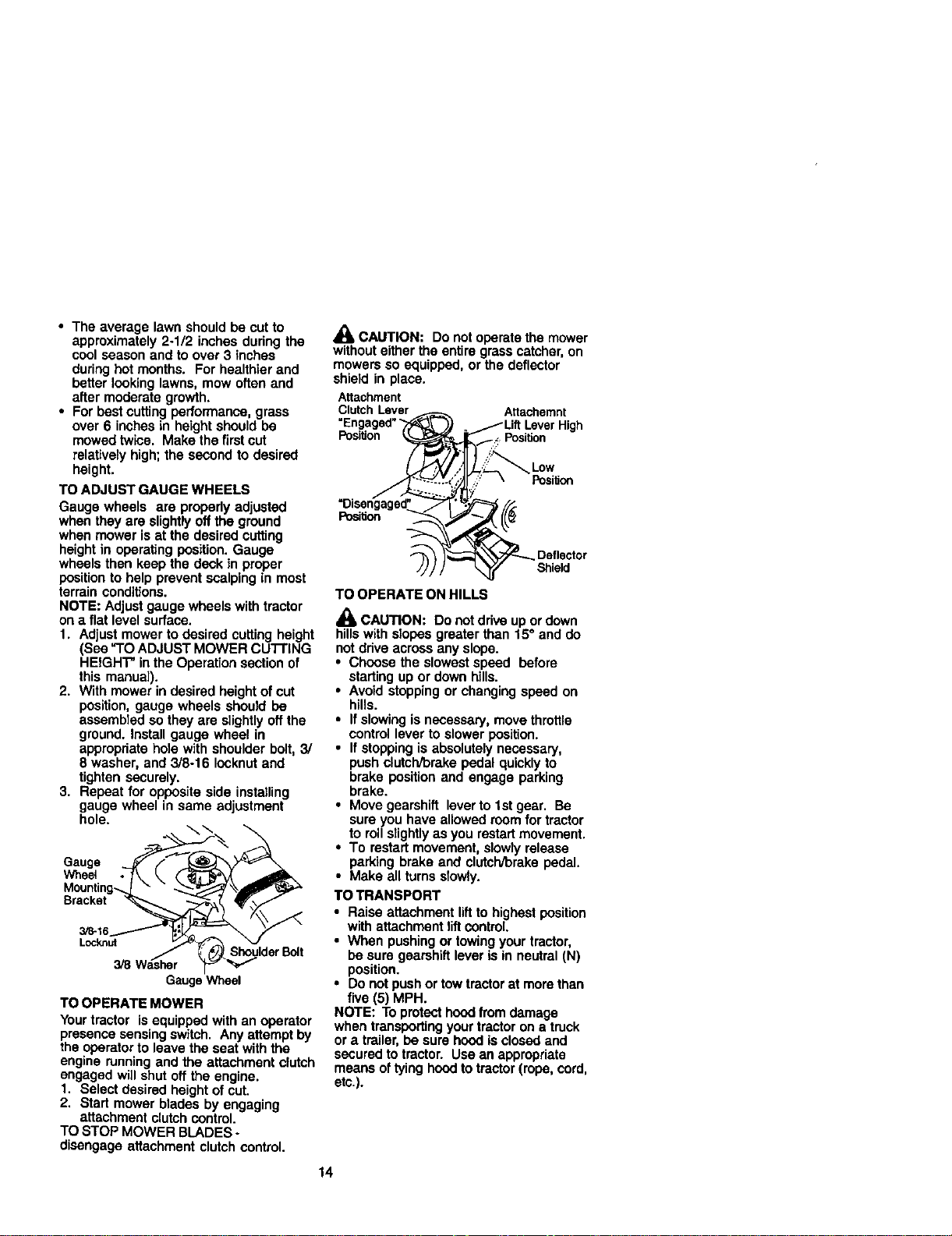
_1, CAUTION: Do not operate the mower
without either the entire grass c_tcher, on
mowers so equipped, or the deflector
shield in place.
Attachment
ClutchLever _ Attachemnt
"Engaged"_ )_ __Lift LeverHigh
Position _._jZ Position
TO OPERATE ON HILLS
CAUTION: Do not drive up or down
hillswith slopes greater than 15° and do
not ddve across any slope.
• Choose the slowest speed before
starting up or clownhills.
• Avoid stopping or changing speed on
hills.
• If slowing is necessary, move throttle
control lever to slower position.
• If stopping is absolutely necessary,
push clutclV'orakepedal quicklyto
brake position and engage parking
brake.
• Move gearshift leverto tst gear, Be
sure you have allowed room for tractor
to roll slightlyas you restartmovement.
• To restart movement, slowly release
parking brake and clutch/brake pedal.
• Make all turns slowly.
TO TRANSPORT
• Raise attachment liftto highest position
with attachment _ittcontrol
• When pushing or towingyour tractor,
be sure gearshift lever is in neutral (N)
position.
• Do not push or tow tractor at morethan
five (5) MPH.
NOTE: To protect hoodfrom damage
when transporting your tractor on a truck
or a trailer,be sure hood Lsclosed and
secured to tractor. Use an appropriate
means of tying hoodto tractor (rope, cord,
etc.).
14
TOWING CARTS AND OTHER ATtACH-
MENTS
Tow only the attachments that are
recommended by and comply with
specifcabons of the manufacturer of your
tractor.Use common sense when towing.
Too heavy of a load, while on a slope, is
dangerous. Tires can lose traction with
the ground and cause you to lose control
of yourtractor.
BEFORE STARTING THE ENGINE
CHECK ENGINE OIL LEVEL
The engine in yourtractor has been
shipped, from the factory,already flied
with summer weight oil.
1. Check engine oil with tractor on level
ground.
2. Remove oil fill cap/dipstick and wipe
clean, reinsert the dipstick and screw
cap tight, wait for a few seconds,
remove and read oil level. I1neces-
sary, add oil until "FULL" mark on
dipstick is reached. Do not overfill.
• For cold weather operation you should
change oil for easier starting (See "OIL
VISCOSITY CHART" inthe Maintenance
section of this manual).
• To change engine oil, see the Mainte-
nance section in this manual.
ADD GASOLINE
• Fillfuel tank. Use fresh, clean, regular
unleaded gasoline with a minimum of
87 octane. (Use of leaded gasoline
will increase carbon and lead oxide
deposits and reduce valve life). Do not
mix oil with gasoline. Purchase fuel in
quantities that can be used within 30
days to assure fuel freshness.
IMPORTANT: When operating in
temperatures below32°F(0°C), use fresh,
clean winter grade gasoline to help
insure good cold weather starting.
_,WARNING: Experience indicates that
alcohol blended fuels (called gasohol or
using ethanol or methanol) can attract
moisture which leads to separation and
formation ofacids dudng storage. Acidic
gas can damage the fuel system of an
engine while in storage. To avoid engine
problems, the fuel system should be
emptied before storage of 30 days or
longer. Drain the gas tank, start the
engine and let it run untilthe fuel lines
and carburetor are empty.
Use fresh fuel next season. See Storage
Instructionsfor additional information.
Never use engine or carburetor cleaner
products in the fuel tank or permanent
damage may occur.
_,CAUTION: Fill to bottom of gas tank
filler neck. Do not overfill. Wipe off any
spilled oil or fuel. Do not store, spill or
use gasoline near an open flame.
TO START ENGINE
When startJngthe engineforthefirsttime orif
theangine has runout offsel, itwilltake extra
crankinglimeto movefuelfromthe tankto
the engine.
1. Sit on seat in operating position,
depress clutch/orake pedal and set
parking brake.
2. Place gear shift lever in neutral (N)
position.
3. Move attachment clutchto "DISEN-
GAGED" position.
4. Move throttle control to choke position.
NOTE: Beforestarting, readthe warm and
coldstarting procedures below.
5. Insert key into ignition and turn key
clockwise to "START" position and
release key as soon as engine starts.
Do not run starter continuously for
more than fifteen seconds per minute.
Ifthe engine does not start after
several attempts, move throttle control
to fast position, wait a few minutes and
try again. If engine still does not start,
move the throttle control back to the
choke position and retry.
WARM WEATHER STARTING(50° F and
above)
6. When engine starts, move the throttle
control to the fast position.
• The attachments and ground drive can
now be used. If the engine does not
accept the load, restart the engine and
allow it to warm up for one minute
using the choke as described above.
COLD WEATHER STARTING( 50° F and
below)
6. When engine starts, allow engine to
run with the throttle control in the
choke position until the engine runs
roughly,then move throttle control to
fast position. This may require an
engine warm-up pedod from several
seconds to several minutes, depend-
ing on the temperature.
15
• The attachments can also be used
during the engine warm-up pedod.
NOTE: Ifat a highal_tude(above3000 feet)
or incoldtemperaturss(below32 F)the
carburetorfuelmixturemay needtobe
adjustedforbestenginepedormance.See
"TOADJUST CARBURETOR" intheService
and Adj_ts sectionofthismanual.
MOWING TIPS
• Mower should be property leveled for
best mowing performance. See "TO
LEVEL MOWER HOUSING" in the
Service and Adjustments section of this
manual.
• The left hand side of mower should be
used for trimming.
• DAve so that clippings are discharged
onto the area that has been cut. Have
the cut area to the rightof the tractor.
This will resultin a more even distribu-
tion of clippings and more uniform
cutting.
• When mowing largo areas, start by
turning to the right so that clippings will
discharge away from shrubs, fences,
driveways, etc. After one or two
rounds, mow in the opposite direction
making left hand turns untilfinished.
• If grass is extremely tail, itshould be
mowed twice to reduce load and
possible fire hazard from dried clip-
pings. Make first cut relatively high; the
second to the desired height.
• Do not mow grass when itis wet. Wet
grass will plug mower and leave
undesirable clumps. Allow grass to dry
before mowing.
• Always operateengineatfutlthrottle
when mowing to assure better mowing
performance and proper discharge of
material. Regulate ground speed by
selecting a tow enough gear to give the
mower cuttingperformance as well as
the qualityof cut desired.
• When operating attachments, select a
ground speed that will suit the terrain
and give best performance of the
attachment being used.
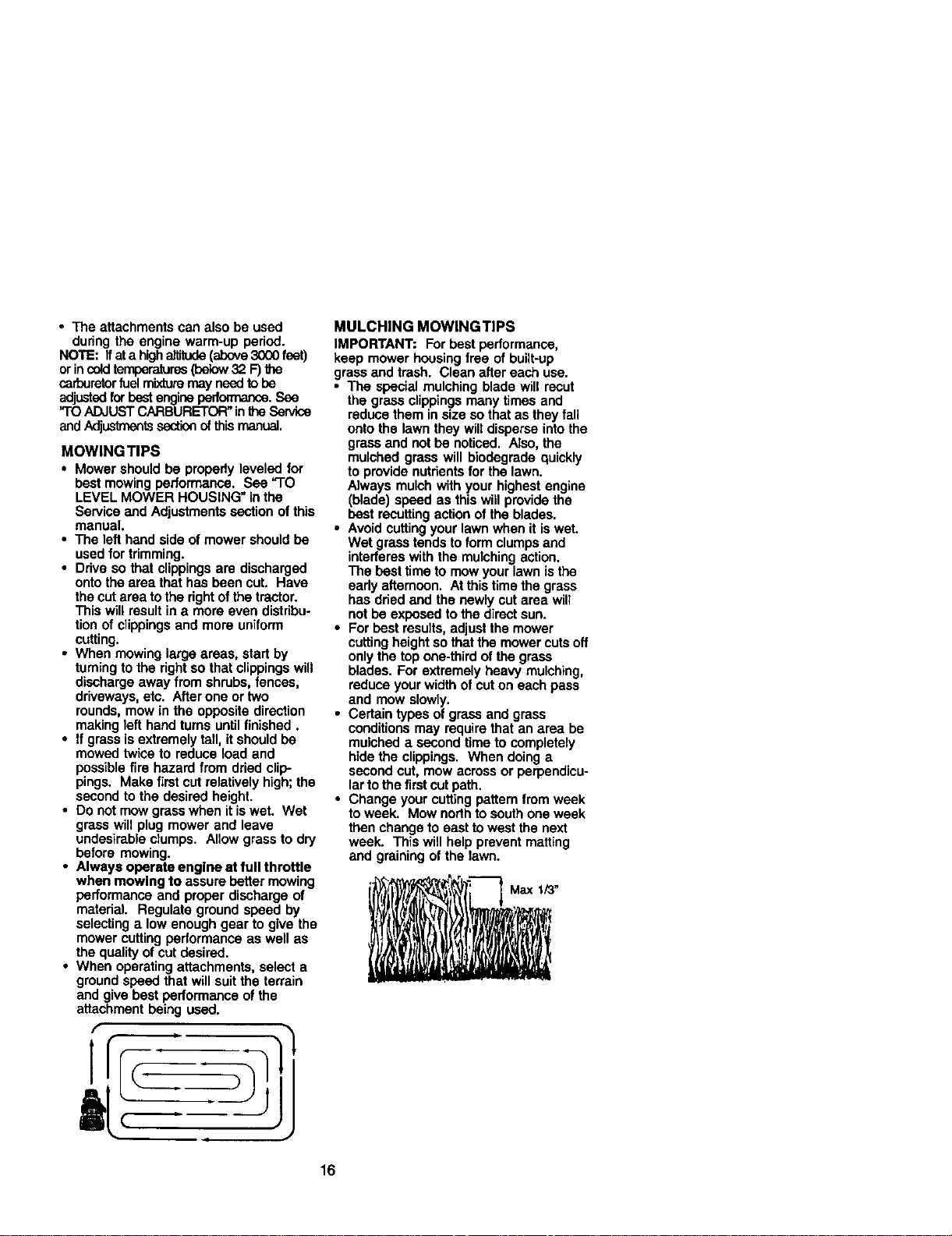
MULCHING MOWINGTIPS
IMPORTANT: For best performance,
keep mower housing free of built-up
grass and trash. Clean after each use.
• The special mulching blade will recut
the grass clippings many times and
reduce them in size so that as they fall
onto the lawn they will disperse intothe
grass and not be noticed. Also, the
mulched grass will biodegrade quickly
to provide nutrientsfor the lawn.
Always mulch with your highest engine
(blade) speed as this will provide the
best recoffing actionof the blades.
• Avoid cuttingyour lawn when it is wet.
Wet grass tends to form clumps and
interferes with the mulching action.
The best time to mow your lawn isthe
eedy afternoon. At this time the grass
has dried and the newly cut area will
not be exposed to the direct sun.
• For best results, adjust the mower
cutting height so thatthe mower cuts off
onlythe top one-third of the grass
blades. For extremely heavy mulching,
reduce your width of cut on each pass
and mow slowly.
• Certain types of grass and grass
conditions may require that an area be
mulched a second time to completely
hidethe clippings. When doing a
second cut, mow across or perpendicu-
larto the first cut path.
• Change your cuffingpattern from week
to week. Mow nodh to south one week
then change to east to west the next
week. This will help prevent matting
and graining of the lawn.
16
.,.NTE.,NC SCHEOULE
Cho__roPreSsure 5/
C_eck OpenCor Pmsena_
T InterlockSysWrns 5/
Sharpe_ReplaceMowerBlades t/,
R C_ansnfy _ Tem_m 5/ 5/
Ched¢ Tmnsa_e Co_r_ 5/
AdjustB_adoBelt(s)Tot-,,leo 5/_
_lJustMo6onDdveBea(s)T_
(_eck Engine Oil Le_ V _ f _
Clean Air Screen 5/=
i_ In_pe_t MU ffleriSpark ,_tef 5/
ReplaceOilRner{Ifequipped) I_.:
N CleanE_r_ Coom_gRns t_'=
R_ sparkP_ 5/ 5/
Replace Air Rlte¢ Paper Cadrldge 5/2 :
Replace FUe#Rfl_" 5/
2- s_i_ _1 et,m w_ _ I_d_ o_du_y¢e_dilia_
3 -g e_ VAI__i Ill,or,_%tp_ol o_*_y50 ho_l.
GENERAL RECOMMENDATIONS
The warranty onthis tractordoes not cover
items that have been subjected to operator
abuse or negligence. To receive fullvalue
from the warranty,operator must maintain
tractoras instructedin this manual.
Some adjustmentswillneed to be made
periodicallyto property maintain your
tractor.
All adjustments inthe Service and
Adjustmentssection ofthis manual should
be checked at least once each season.
• Once a year you shouldreplace the
spark plug, clean or replace air filter,and
check blades and belts forwear. A new
spark plug and clean air filter assure
proper air-fuel mixture and help your
engine run better and last longer.
BEFORE EACH USE
1. Check engine oil level.
2. Check brake operation.
3. Check tire pressure.
7 -T@+_,enI.ni_l md_pl_t bolt to 36 ilL4b#,mse_'_m+
_ _otover_hzo_
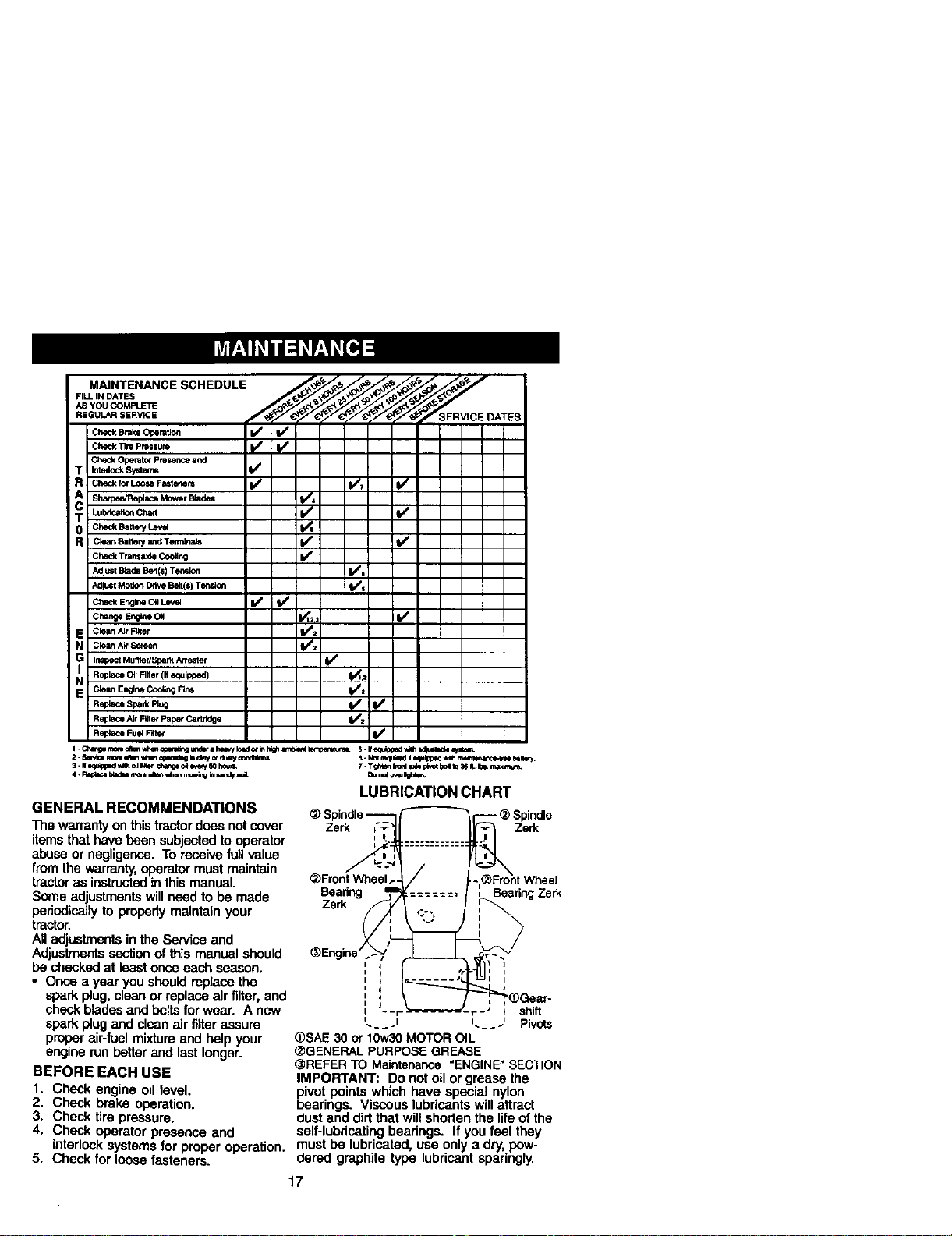
LUBRICATION CHART
- _ Spindle
Zerk Zerk
_)Front Wheel
Beadng
Zerk
Beadng Ze_
I
_=_-- shift
........ Pivots
@SAE30 or 10w30MOTOROIL
_GENERAL PURPOSEGREASE
_REFER TO Maintenance=ENGINE"SECTION
IMPORTANT: Do not oil or grease the
pivot pointswhich have special nylon
bearings, Viscous lubricants willattract
dust and did that wileshorten the lifeof the
4. Check operator presence and self-lubriceting bearings. If you feel they
interlock systems for proper operation, must be lubricated, use only a dry, pow-
5. Check for loose fasteners, dered graphite type lubricant sparingly.
17
TRACTOR
Always observe safety rules when per-
forming any maintenance.
BRAKE OPERATION
If tractorrequires more than six (6) feet
stopping distance at high speed in highest
gear, then brake must be adjusted. (See
"TO ADJUST BRAKE" in the Service and
Adjustmentssection of this manual).
TIRES
• Maintain proper air pressure in all tires
(See "PRODUCT SPECIFICATIONS"
section of this manual).
• Keep tires free of gasoline, oil, or insect
control chemicals which can harm
rubber.
• Avoid stumps, stones, deep ruts, sharp
objects and other hazards that may
cause tire damage.
NOTE: Toseal tire punctures and prevent
flat tires due to slow leaks, tire sealant may
be purchased from your local parts dealer.
Tire sealant also prevents tire dry rotand
corrosion.
OPERATOR PRESENCE SYSTEM
Be sure operator presence and interlock
systems are workingproperly. If your
tractor does not function as described,
repair the problem immediately.
• The engine should not start unless the
brake pedal is fully depressed and
attachment clutchcontrol is in the
disengaged position.
• When the engine is running, any attempt
by the operator to leave the seat without
first setting the parking brake should
shut off the engine.
• When the engine is running and the
attachment clutch is engaged, any
attempt by the operator to leave the seat
should shut off the engine.
• The attachment clutch should never
operate unless the operator is in the
seat.
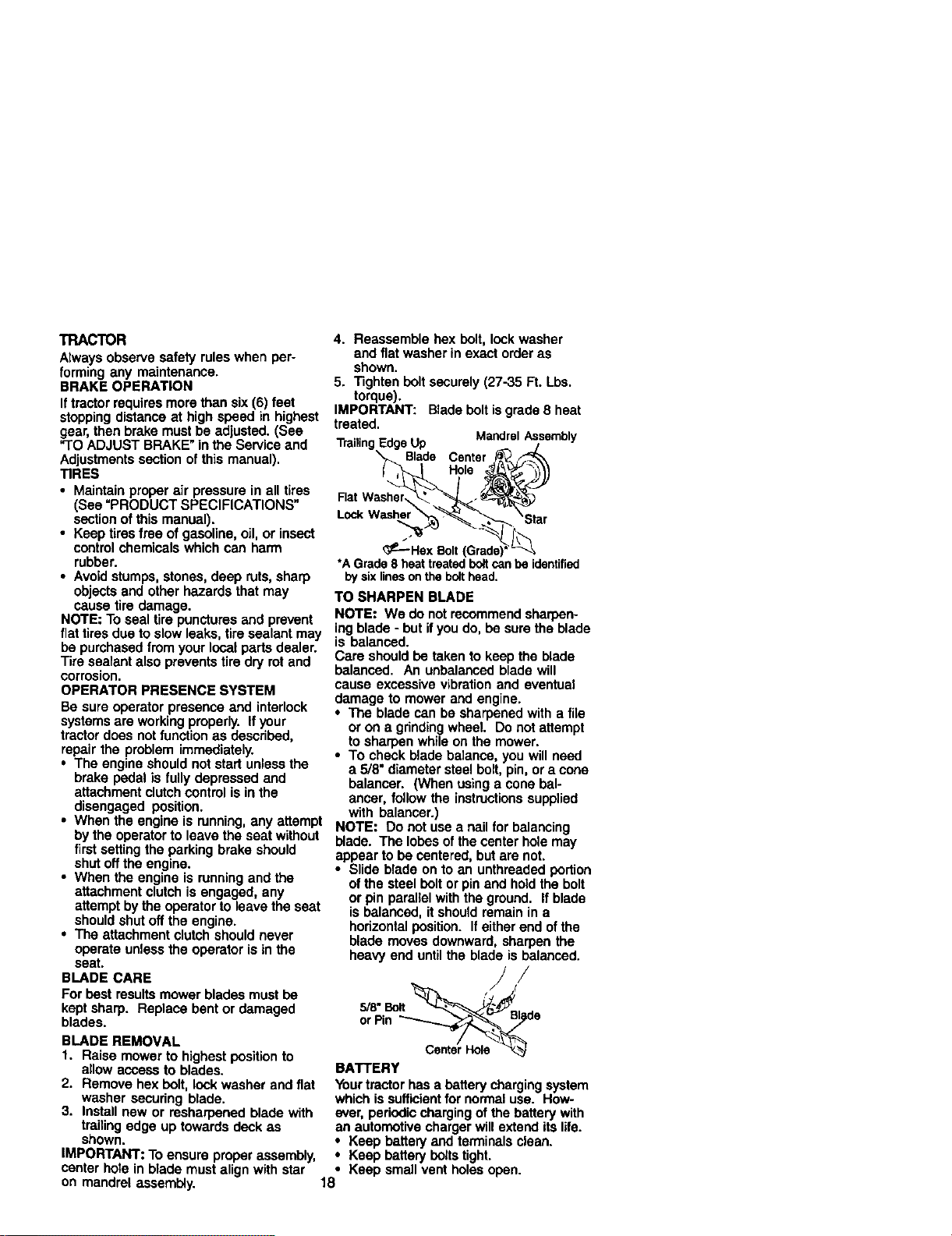
BLADE CARE
For best results mower blades must be
kept sharp. Replace bent or damaged
blades.
BLADE REMOVAL
1. Raise mower to highestposition to
allow access to blades.
2. Remove hex bolt, lock washer and flat
washer securing blade.
3. Install new or resharpened blade with
trailing edge up towards deck as
shown.
IMPORTANT: Toensure proper assembly,
center hote in blade must align with star
on mandrel assembly.
4. Reassemble hex bolt, lock washer
and flat washer in exact order as
shown.
5. Tighten bolt securely (27-35 Ft. Lbs.
torque).
IMPORTANT: Blade boltis grade 8 heat
treated.
EdgeUp MandrelAssembly
Blade Center
Hole
Flat Washer
Lock Weshe
_£---HSXBolt *_
*AGrade8 heattreatedboltcanhe identified
bysixlinesonthebolthead.
TO SHARPEN BLADE
NOTE: We do not recommend sharpen-
ing blade - but if you do, be sure the blade
is balanced.
Care should be taken to keep the blade
balanced. An unbalanced blade will
cause excessive vibration and eventual
damage to mower and engine.
• The blade can be sharpened with a file
or on a grindingwheel. Do not attempt
to sharpen while on the mower.
• To check blade balance, you will need
a 5/8" diameter steel bolt,pin, or a cone
balancer. (When using a cone bal-
ancer, follow the instructionssupplied
with balancer.)
NOTE: Do not use a nail for balancing
blade. The lobes ofthe center hole may
appear to be centered, but are not.
• Slide blade on to an unthreeded portion
of the steel bolt or pin and hold the bolt
or pin parallel with the ground. If blade
is balanced, it should remain in a
horizontal position. Ifeither end of the
blade moves downward, sharpen the
heavy end until the blade is balanced.
or Pin _%'_de
BATTERY
Your tractor has a battery chargingsystem
which issufficientfor normaluse. How-
ever, periodic chargingof the battery with
an automotive charger will extend its life.
• Keep battery and terminals clean.
• Keep battery boltstight.
• Keep small vent holes open.
18
• Recharge at 6-10 amperes for 1 hour.
NOTE: The original equipment battery on
your tractor is maintenance free. Do not
attempt to open or remove caps or covers.
Adding or checking level of electrolyte is
notnecessary.
TO CLEAN BA'I-rERY AND TERMINALS
Corrosion and dirton the battery and
terminals can cause the battery to "leak"
power.
1. Open battery box door.
2. Disconnect BLACK battery cable first
then RED battery cable and remove
batteryfromtractor.
3. Rinse the battery with plain water and
dry.
4. Clean terminals and battery cable
ends with wire brush until bright.
5. Coat terminals with grease or petro-
leum jelly.
6. Reinstall battery (See "REPLACING
BATI'ERY" in the SERVICE AND
ADJUSTMENTS section ofthis
manual).
V-BELTS
Check V-bolts for deterioration and wear
after 100 hours of operation and replace if
necessary. The beltsare not adjustable.
Replace beltsif they begin to slip from
wear.
TRANSAXLE COOLING
Keep transaxle free from build-up of dirt
and chaff which can restrictcooling.
ENGINE
LUBRICATION
Only use highqualitydetergent oil rated
withAPI service classificationSF-SJ.
Select the oil'sSAE viscositygrade
accordingto your expected operating
temperature.
Check the crankcase oil level before
startingthe engine and after each eight (8)
hours of operation. Tightenoil fillcap/
dipsticksecurely each time you check the
oil level.
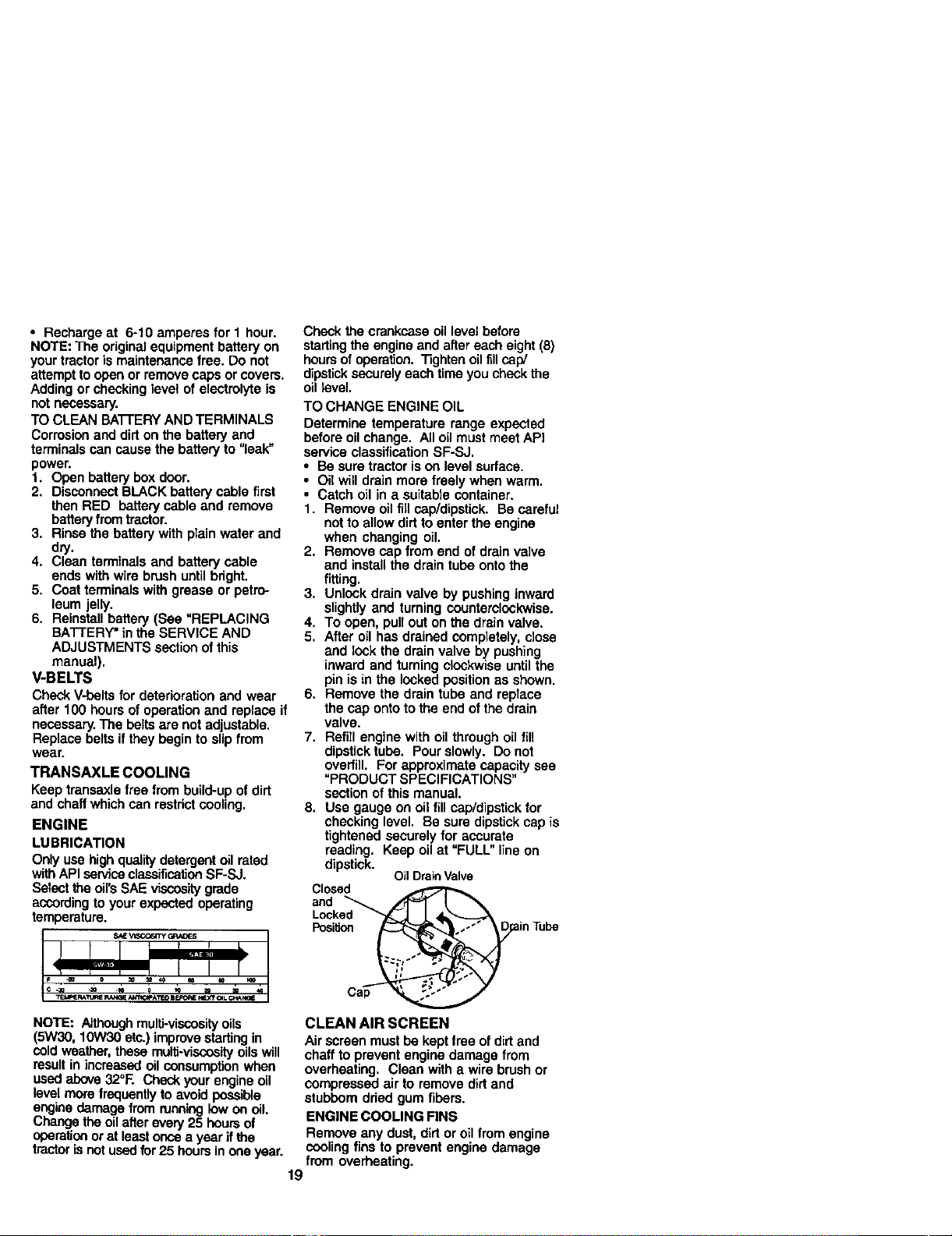
TO CHANGE ENGINE OIL
Determine temperature range expected
before oil change. All oil must meet API
service classification SF-SJ.
• Be sure tractor is on level surface.
• Oil will drain more freely when warm.
• Catch oil in a suitable container.
1. Remove oil fill cap/dipstick. Be careful
notto allow dirt to enter the engine
when changing oil.
2. Remove cap from end of drain valve
and install the drain tube onto the
fitting.
3. Unlock drain valve by pushing inward
slightly and turning counterclockwise.
4. To open, pull out on the drain valve.
5. After oil has drained completely, close
and lock the drain valve by pushing
inward and turning clockwise until the
pin is in the locked position as shown.
6. Remove the drain tube and replace
the cap onto to the end of the drain
valve.
7. Refill engine with oil through oil fill
dipstick tube. Pour slowly. Do not
overfill. For approximate capacity see
"PRODUCT SPECIFICATIONS"
section of this manual.
8. Use gauge on oil fill cap/dipstick for
checking level. Be sure dipstick cap is
tightened securely for accurate
reading. Keep oil at "FULL" line on
dipstick.
Oil DrainValve
Closed
and
Locked
Posif_n
NOTE: Althoughmulti-viscosityoils
(5W30, 10W30 etc.) improvestartingin
cold weather, these multi-viscosityoilswill
result in increasedoil consumption when
used above 32°E Check your engine oil
level more frequentlyto avoid poss=ble
engine damage from running!ow on oil.
Change theoilafterevery25 hoursof
operationor at leastonce a year ifthe
tractor isnot used for25 hoursin one year.
CLEAN AIR SCREEN
Air screen must be kept free of dirtand
chaff to prevent engine damage from
overheating. Clean with a wire brush or
compressed air to remove dirt and
stubborn dried gum fibers.
ENGINE COOLING FINS
Remove any dust, dirt or oil from engine
coolingfins to prevent engine damage
from overheating.
19
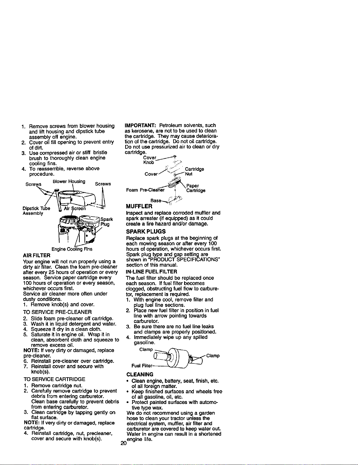
1.Removescrewsfromblowerhousing
andlifthousingand dipstick tube
assembly off engine.
2. Cover oil fill opening to prevent entry
ofdirt.
3. Use compressed airor stiffbristle
brushtothoroughlycleanengine
coolingfins.
4. To reassemble,reverseabove
procedure.
S A BlowerHousing _.......
EngineCoolingFins
AIR FILTER
Your engine will not run properly using a
dirty air filter. Clean the foam pre-cleaner
after every 25 hours of operation or every
season. Service paper cartridge every
100 hours of operation or every season,
whichever occurs first.
Service air cleaner more often under
dusty conditions.
1. Remove knob(s) and cover.
TO SERVICE PRE-CLEANER
2. Slide foam pre-cleaner off cartddge.
3. Wash it in liquid detergent and water,
4. Squeeze itdry in a clean cloth.
5. Saturate it in engine oil. Wrap it in
clean, absorbent cloth and squeeze to
remove excess oil
NOTE: If very dirty or damaged, replace
pre-cleaner.
6. Reinstall pre-cleaner over cartridge.
7. Reinstall cover and secure with
knob(s).
TO SERVICE CARTRIDGE
1. Remove cartridge nut.
2. Carefully remove cartridge to prevent
debns from entering carburetor.
Clean base carefully to prevent debris
from entering carburetor.
3. Clean cartridge by tapping gently on
flat sudace.
NOTE: If very dirty or damaged, replace
cartridge.
4. Reinstall cartddge, nut, precleaner,
cover and secure with knob(s).
IMPORTANT: Petroleum solvents,such
as kerosene, are not to be used to clean
the cartridge. They may cause deteriora-
tion of the cartridge. Do not oil cartridge.
Do not use pressudzed air to clean or dry
cartridge.
Cover......._
Knob _
Cartridge
_.Paper
Foam Pre-Clea_'-or _ Cartridge
asse.-.._ _"
MUFFLER
Inspect and replace corroded muffler and
spark arrester (if equipped) as it could
create a fire hazard and/or damage.
SPARK PLUGS
Replace spark plugs at the beginning of
each mowing season or after every 100
hours of operation, whichever occurs first,
Spark plug type and gap setting are
shown in =PRODUCT SPECIFICATIONS"
section of this manusL
IN-LINE FUEL FILTER
The fuel filter should be replaced once
each season. If fuel filterbecomes
clogged, obstructingfuel flow to carbure-
tor, replacement is required.
1. With engine cool, remove filter and
plug fuel line sections.
2, Place new fuel filter in positionin fuel
line with arrow pointingtowards
carburetor.
3. Be sure there are no fuel line leaks
and clamps are properly positioned.
4, Immediately wipe up any spilled
gasoline.
Clamp_
FuelFlitor-------_,_J_L__._J --
CLEANING
• Clean engine, battery, seat, finish, etc.
of all foreign matter.
• Keep finished surfaces and wheels free
of all gasoline, oiI, etc.
• Protect painted surfaces with automo-
tive type wax.
We do not recommend using a garden
hose to clean your tractor unless the
electrical system, muffler,air filter and
carburetor are covered to keep water out.
Water in engine can resultin a shortened
20engine life.
,_CAUTION: BEFORE PERFORMING ANY SERVICE OR ADJUSTMENTS:
1. Depress clutch/broke pedal fully and set parking brake.
2. Place gearshift lever in neutral (N) position.
3. Place attachment clutch in "DISENGAGED" position,
4. Turn ignitionkey "OFF" and remove key.
5. Make sure the blades and all moving pads have completely stopped,
6, Disconnect spark plug wire from spark plug and place wire where it cannot
come in contact with ptug.
TRACTOR
TO REMOVE MOWER
Mower will be easier to remove from the
rightside oftractor.
1. Place attachment clutch in =DISEN-
GAGED" position.
2. Move attachment liftlever forward to
lower mower to its lowest position.
3. Roll belt off engine pulley.
4. Remove small retainer spring, and lift
clutch spdng off pulley bolt.
5. Remove large retainer spring, slide
collar off and push housing guide out
of bracket.
6. Disconnect anti-swaybar from chassis
bracket by removing retainer spring.
7. Disconnect suspension arms from
roar deck brackets by removing
retainer spdngs.
8. Disconnect front links from deck by
removing retainer spdngs.
9. Raise lift lever to raise suspension
arms. Slide mower out from under
tractor.
IMPORTANT: Itan attachment other than
the mower deck is to be mounted on the
tractor,remove the front links and hook
the clutchspdng Into square hole in
frame.
TO INSTALL MOWER
1. Raise attachment lift lever to its
highest position.
2. Slide mower under tractor with
deflector shield to rightside of tractor.
3. Lower liftlever to its lowest position.
4. Install mower in reverse order of
removal instructions.
TO LEVEL MOWER HOUSING
Adjust the mower while tractor is parked
on level ground or driveway. Make sure
tires are properly inflated (See "PROD-
UCT SPECIFICATIONS" sectionof this
manual). If tires are over or
underinflated, you will not properly adjust
your mower.
SIDE-TO-SIDE ADJUSTMENT
• Raise mower to its highest position.
• At the midpointof both sidesof mower,
measure height from bottom edge of
mower to ground. Distance "A"on
both sides of mower should be the
same or within 1/4" of each other.
Small Retainer Spdng
Clutch S
Square Hole
Retainer S
Anti.Sway
Collar
(Both Sides)
Housing Guide
Large Retainer Spring
21
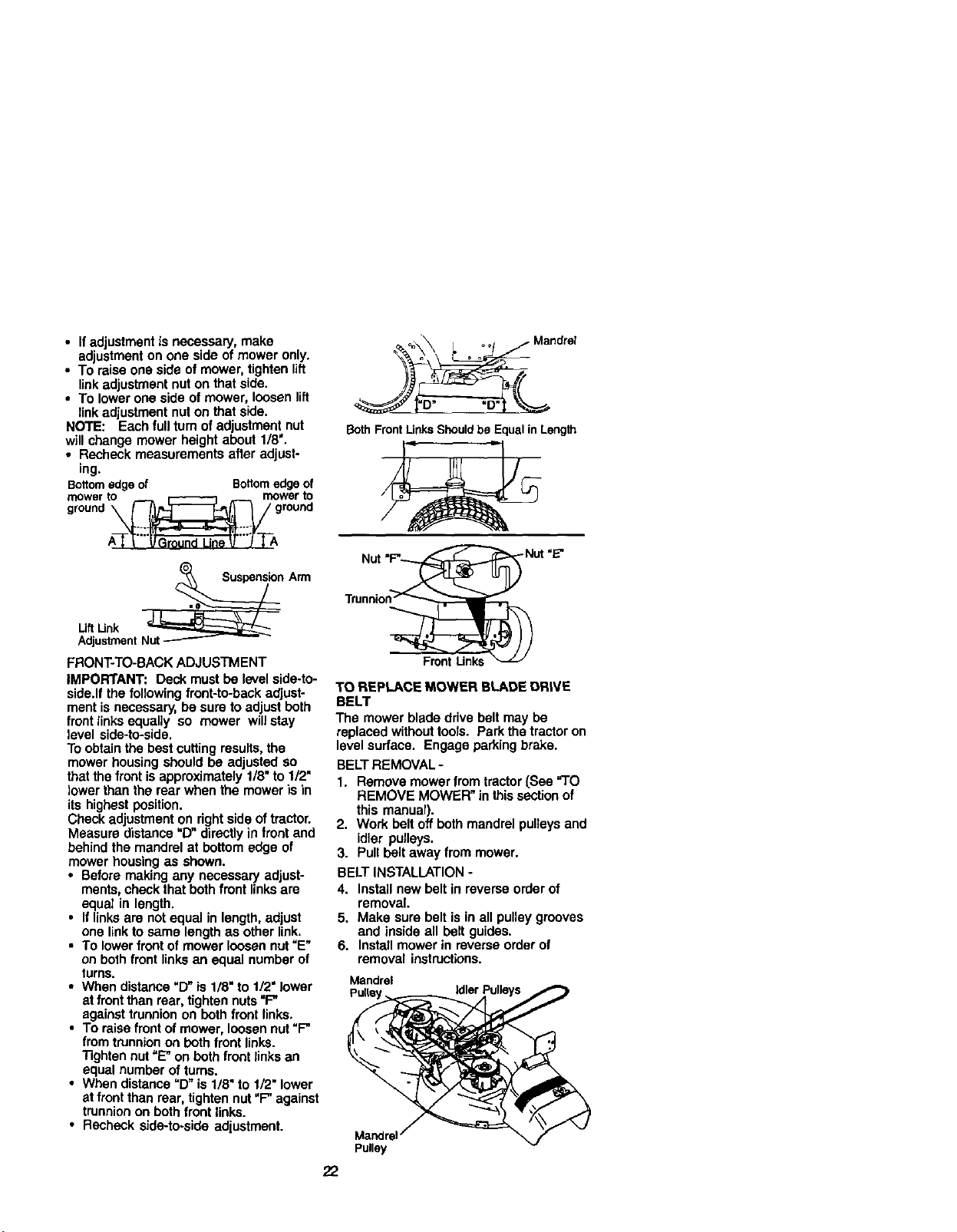
• If adjustment is necessary, make
adjustmenton one side of mower only.
• To raise one side of mower, tighten lift
linkadjustment nut on that side.
• To lower one side of mower, loosen lift
linkadjustment nut on that side.
NOTE: Each full tum ofadjustment nut
will change mower height about 1/8'.
• Recheck measurements after adjust-
ing.
Bottomedgeof Bottomedge of
grrn_oWne_t_rn_roW_ur nt_
A_A
LiftLink __=_€_;;;:;;_;_--_Z_ n
Arm
Adjustment Nut --------- --
FRONT-TO-BACK ADJUSTMENT
IMPORTANT: Deck must be levelside-to-
side.If the following front-to-beck adjust-
ment is necessary, be sure to adjust beth
front links equally so mower will stay
level side-to-side.
To obtain the best cutting results, the
mower housing should be adjusted so
that the front isapproximately 1/8" to 1/2"
lower than the rear when the mower is in
its highest position.
Check adjustment on rightside of tractor.
Measure distance "D" directlyin trent and
behind the mandrel at bottom edge of
mower housing as shown.
• Before making any necessary adjust-
ments, check that beth front links are
equal in length.
• If links are notequal in length, adjust
one link to same length as other link.
• To lowerfront of mower loosen nut "E"
on both front links an equal number of
turns.
• When distance "D" is 1/8" to 1/2" lower
at front than rear, tighten nuts=F"
against trunnion on beth front links,
• To raise front of mower, loosen nut"F"
from trunnionon beth front links.
"Rghtennut =E"on beth front links an
equal number of turns.
• When distance "D" is 1/8" to 1/2" lower
at frontthan rear, tighten nut "F" against
trunnionon both front links.
• Recheck side-to-side adjustment.
_%,_ ; _ / Mandrel
BothFrontUnksShouldbe Equalin Length
.ut-
Trunnion_
FrontLinks
TO REPLACE MOWER BLADE DRIVE
BELT
The mower blade drive belt may be
replaced without tools. Park the tractor on
level surface. Engage parking brake.
BELT REMOVAL -
1. Remove mower from tractor (See TO
REMOVE MOWER" in this section of
this manual).
2. Work belt off both mandrel pulleysand
idler pulleys.
3. Pull belt away from mower.
BELT INSTALLATION -
4. Install new belt in reverse order of
removal.
5. Make sure belt is in all pulley grooves
and inside all belt guides.
6. Install mower in reverse order of
removal instructions.
Mandrel
Mandrel
Pulley
22
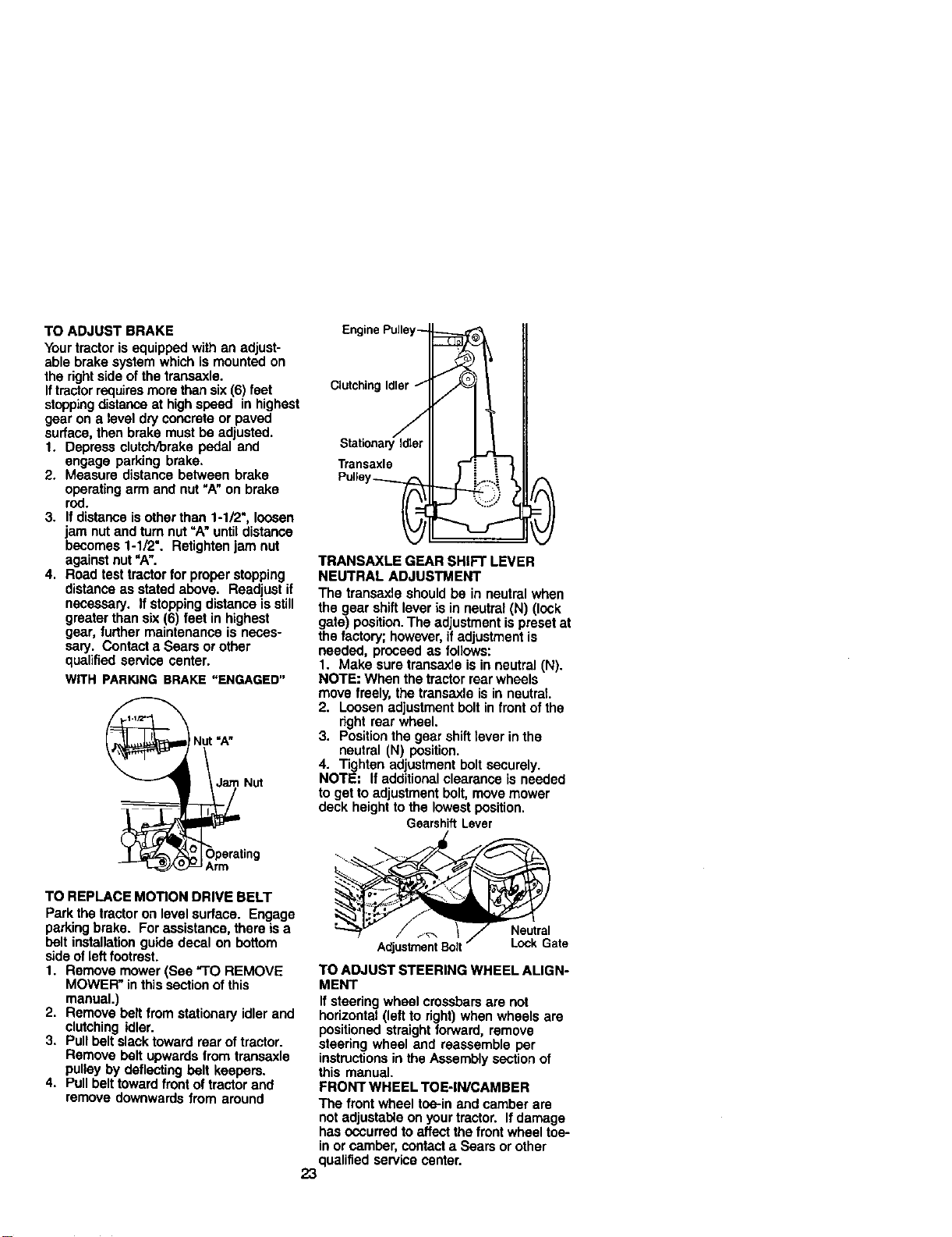
TO ADJUST BRAKE
Your tractoris equipped with an adjust-
able brake system which is mounted on
the rightside of the transaxle.
Iftractorrequires more than six(6) feet
stoppingdistance at highspeed in highest
gear on a level dry concrete or paved
surface, then brake must be adjusted.
t. Depress clutch/brake pedal and
engage parking brake.
2. Measure distance between brake
operating arm and nut "A"on brake
rod.
3. If distance isother than 1-1/2", loosen
jam nut and turnnut "A"until distance
becomes 1-1/2". Retighten jam nut
against nut"A".
4. Road test tractor for proper stopping
distanceas stated above. Readjust if
necessary. If stopping distance is still
greater than six (6) feet in highest
gear, further maintenance is neces-
sary. Contact a Sears or other
qualified service center.
WITH PARKING BRAKE "ENGAGED"
Nut=A"
Nut
Operating
Arm
TO REPLACE MOTION DRIVE BELT
Park the tractoron level surface. Engage
parkingbrake. For assistance, there is a
belt installation guide decal on bottom
side ofleft footrest.
1. Remove mower (See "TO REMOVE
MOWER" in this section of this
manual.)
2. Remove belt from stationary idler and
clutching idler.
3. Pull belt slack toward rear of tractor.
Remove belt upwards from transaxle
pulley by deflecting belt keepers.
4. Pull belt towardfront of tractor and
remove downwards from around
EnginePulley-]_
ClutchingIdler_
],1"
StationaryIdler _
Transaxle *'-"
TRANSAXLE GEAR SHIFT LEVER
NEUTRAL ADJUSTMENT
The transaxle should be in neutral when
the gear shift lever is in neutral (N) (lock
gate) position. The adjustment is preset at
the factory; however,if adjustment is
needed, proceed as tol]ows:
1. Make sure transaxla is in neutral (N).
NOTE: When the tractor rear wheels
move freely, the transaxle is in neutral
2. Loosen adjustment bolt in front of the
right rear wheel.
3. Position the gear shift lever in the
neutral (N) position.
4. Tighten adjustment bolt securely.
NOTE: If additional clearance is needed
to get to adjustment bolt, move mower
deck height to the lowest position.
GearshiftLever
_ate
TO ADJUST STEERING WHEEL ALIGN-
MENT
If steering wheel crossbars are not
horizontal (left to right) when wheels are
positioned straight forward, remove
steering wheel and reassemble per
instructionsin the Assembly section of
this manual.
FRONT WHEEL TOE-IN/CAMBER
The front wheel toe-in and camber are
not adjustable on your tractor. If damage
has occurred to affect the front wheel toe-
in or camber, contact a Sears or other
qualified service center.
23
TOREMOVEWHEELFORREPAIRS
1. Blockupaxlesecurely.
2. Removeaxle cover, retaining ring and
washers to allow wheel removal (rear
wheel contains a square key - Do not
lose).
3. Repair tire and reassemble.
NOTE: On rear wheels only: align
grooves in rear wheel hub and axle.
Insertsquare key.
4. Replace washers and snap retaining
ring securely in axTegroove.
5. Replace axle cover.
NOTE: To seal tire punctures and prevent
flat tires due to slow leaks, tire sealant
may be purchased from your local parts
dealer.Tire sealant also prevents tire dry
rot and corrosion.
_XolveerR_a_h_O
TO START ENGINE WITH A WEAK
BATTERY
_, ,CAUTION:_ad-add batteriesgenerate
exptssivega.s_, t_eepsparks,Ilam_ and
smokingmaterialsaway from batteries.
Alwayswear eye protedJonwhen around
batteries.
ffyourbatteryistcoweak to stadthe engine,it
shouldbe recharged. (See "BA3-1"ERY"inthe
MAINTENANCE sectionofth'_srnanua_).
If"jumpercables"am usedforemergency
starting,followthis procedure:
IMPORTANT: Yourtractorisequippedwitha
12 voltnegativegroundedsystem.The other
vehicalmust also be a 12volt negalJve
groundedsystem.Do notuseyourtractor
batterytostartotherveh'_,es.
TO A'F]'ACHJUMPER CABLES -
1. Connect each end of the RED cable to
the POSITIVE (+) terminal ofeach
battery, taking care not toshort
against chassis.
2. Connect one end of the BLACK cable
to the NEGATIVE (-) terminal of fully
charged battery.
3. Connect the other end of the BLACK
cable to good CHASSIS GROUND,
away from fuel tank and battery.
TO REMOVE CABLES, REVERSE ORDER-
1. BLACK cable first from chassis and
then from the fully charged battery.
2. RED cable last from both batteries.
24
PositiveTerminal Terminal
Charged
Positive
Terminal \Negative
Terminal
REPLACING BA'I-I'ERY
A, CAUTION DOnot short batterv
terminals by allowing a wrench of any
other object to contact both terminals at
the same time. Before connectingbattery,
remove metal bracelets, wristwatch
bands, rings, etc.
Positiveterminal must be connected first
to prevent sparking from accidental
grounding.
1, Lift seat pan to raised position and
open battery box door.
2. Disconnect BLACK battery cable first
then RED battery cable and carefully
remove battery from tractor.
3. Install new battery with terminals in
same position as old battery.
4. First connect RED batterycable to
positive (+) terminal with hex bolt and
keps nut as shown. Tighten securely.
5. Connect BLACK grounding cable to
negative (-) terminal with remaining
hex bolt and keps nut. Tighten
securely.
6. Close battery box door.
Keps_ Hex
Nut _, BoR
Positive (Red) Cable Negative (Black)
Cable
TO REPLACE HEADLIGHT BULB
1. Raise hood.
2. Pullbulb holderout of the hole in the
backside of the grill.
3. Replace bulb in holder and push bulb
holdersecurely back intothe hole in
the backside ofthe gdll.
4. Close hood.
INTERLOCKS AND RELAYS
Loose or damaged wiringmay cause your
tractorto runpoorly,stop running,or
prevent itfrom starting.
• Chock widng. See electricalwiring
diagram in the Repair Pads section.
TO REPLACE FUSE
Replace with 20 amp automotive-type
plug-infuse. The fuse holder is located
behind the dash.
TO REMOVE HOOD AND GRILL AS-
SEMBLY
1. Raise hood.
2. Unsnap headlight wire connector.
3. Stand in frontoftractor. Grasp hood at
sides, tilttoward engine and liftoff of
tractor.
4. To replace, reverse above procedure.
or
ENGINE
Maintenance,repair,or rsplacementof U'e
amieskxl cootroldevicesand systems,which
are betogdone atthe customersexpense,
maybe performedby any non-rcadengine
repairestablishmentor individual.Warranty
repelrsmustbe performedbyan authedzed
enginemanufacturersserviceoutlet.
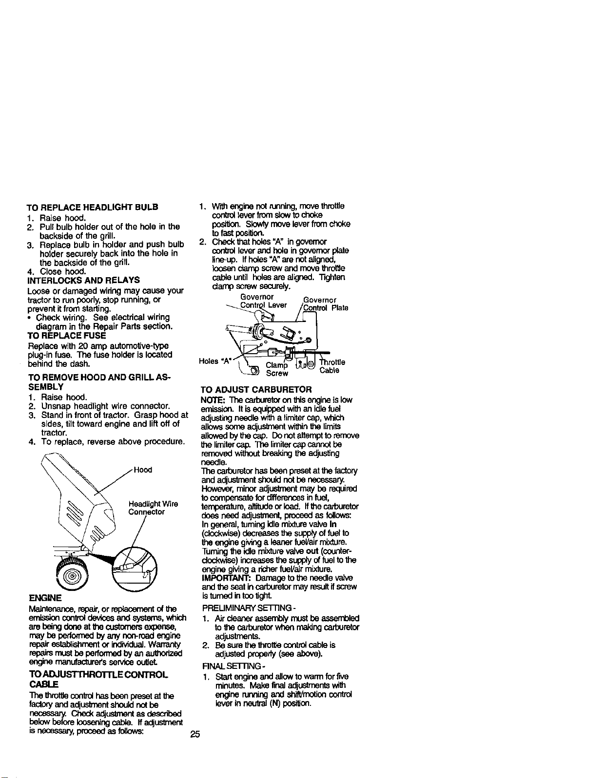
TO ADJUSTI'HROTrLE CONTROL
CABLE
The thmtgeconbolhasbeanpresetat the
factory and adjustmentshouldnotbe
necessary. Ched_adjusUnentes described
roelowbefore Ionesningcable. Ifadj_
necessary,proc_ asfollows:
1. W_henginenot running,movethrottle
controltever f_ stowtochoke
position. Sk_ly moveleverfrornchoke
tofastpesitioo.
2. Check that holes"A" in governor
control leverand hole in governorplate
line-up, ffholes"A" are not aligned,
kx_sendamp screwand rnove thro_e
cableuntil holesare aligned. "i3ghten
damp screw securely.
Governor Governor
_ Plate
Holes"A"'__.._._Clem_J _.rstUe
Cable
TO ADJUST CARBURETOR
NOTE: The cerburetor onthis engineislow
emission. It isequippedwithan idlefuel
adjustingneedle witha limitercap,which
allowssome adj_nt withinthe limits
allowedbythe cap. Donotattampttoremove
It_ lirn_ercap. Tile limitercap cannctbe
removed without _eaking the adjusting
needle.
The carburetorhasboonpresetat thefsctory
and edjuslment sbeuid not be nesessary.
However, minor adjuslmentmay be required
tocompensatefor d'_erencesinfuel,
ternpereture,anJtudeorload. ffthe carburetor
does need adjuslment,proceedas follows:
In general,turning idle mixture valve In
(dock-wL_)decreases the suPPlYof fuel to
the enginegivinga leanerfueVairmixture.
Turningthe idle mixture valve out (coonter-
dockwise) increases thesupp_ of fueltothe
engine gMng a richer fuel/air mixture.
IMPORTANT: Damagetothe needlevalve
andthe seatincarburetor may resultifscrew
isturnedintootight.
PRELIMINARYSETTING-
1. Airdeaner assernbly mustbe _ed
to the carburetorwhen rnaldngcarburetor
adjustments.
2. Be surethe thmttie control cable is
adjustedproperly(ese above).
RNAL SETrlNG-
t. Stedangine and allowto warmfor five
minutes. Make final adjustmentswith
en_ne runningand shift/motioncontrol
leverinneutral(N)pcei_on.
25
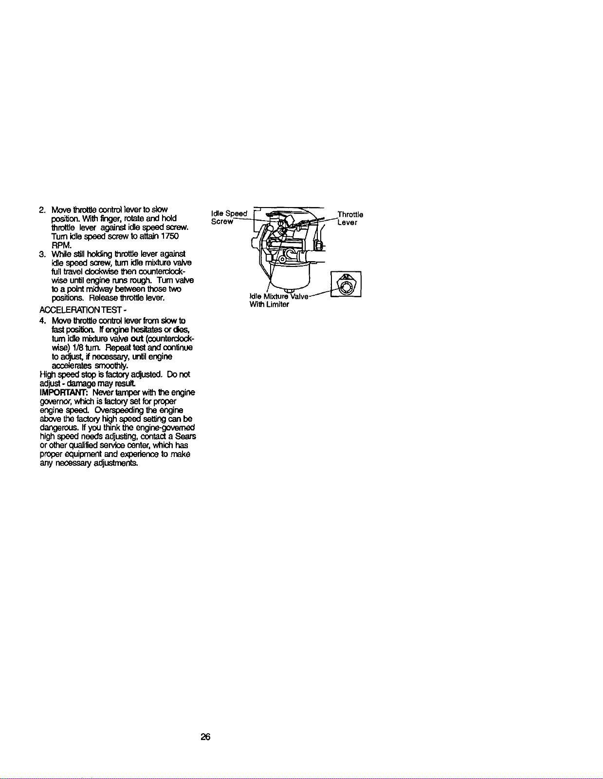
2, Move throt_econtmHeverto slow
pos_on.Withfinger,rotateand hold
throttre lever againstidlespeedscrew.
Turn idlespeedscrewto attain1750
RPM.
3. While s_llholdingthrottlelever against
idlespeed screw,turnidlemixturevelve
full traveldockwL_ thencountercleck-
wise untilenginerunsrough. Turn valve
toa pointmidwaybetweenthosetwo
pos_ons. Release throttlelever.
/_CELERATION TEST -
4. Move throttlecontrelleverfromslewto
fast pos_on, if enginehesitatesorrise,
turnidle mixturevalve out (counterclock-
wise)1/8 tom. Repeattestand conUnue
toadjust, ifnecessary,untilengine
acc_eratessnxx_th_.
Highspeedstopisfactoryadjusted. Donot
adjust- damage may resulL
IMPORTANT: Nevertamperwith_,e engine
governor,whichisfactorysetforproper
enginespeed.Overspeedingtheengine
abovethe factoryhighspeedsetUngcan be
dangerous,if you think the engi_
high speed needs a_usting,contacta Sears
orotherqualified service center,which has
proper equipment and experienceto make
any necessae/adjusbnents.
Idle Speed
With Limiter
26
Immediately prepare your tractor for
storage at the end of the season or if the
tractor will not be used for 30 days or
more.
CAUTION: Never store the tractor
with gasoline in the tank inside a building
where fumes may reach an open flame or
spark. Allow the engine to coot before
storing in any enclosure.
TRACTOR
Remove mower from tractor for winter
storage. When mower isto be stored for
a period oftime, clean it thoroughly,
remove all dirt, grease, leaves, etc. Store
in a clean, dry area,
1. Clean entire tractor (See "CLEANING"
in the Maintenance section of this
manual).
2. Inspect and replace belts, if necessary
(See belt replacement instructionsin
the Service and Adjustmentssection
ofthis manual).
3. Lubricate as shown in the Mainte-
nance section of this manual.
4. Be sure that all nuts, belts and screws
are securely fastened. Inspect moving
parts for damage, breakage and wear.
Replace if necessary.
5. Touch up all rusted or chipped paint
surfaces; sand lightlybefore painting.
BA'n'ERY
• Fullycharge the battery for storage.
• Aftera period of time in storage, battery
may require recharging.
• To help prevent corrosion and power
leakage during tong periods of storage,
battery cables should be disconnected
and battery cleaned thoroughl_ (see
"TO CLEAN BA'I-FERY AND TERMI-
NALS" in the Maintenance section of
this manual).
• After cleaning, leave sables discon-
nected and place cables where they
cannot come in contact with battery
terminals.
• Ifbattery isremoved fromtractor for
storage, do not store battery directly on
concrete or damp surfaces.
ENGINE
FUEL SYSTEM
IMPORTANT: It isimportant toprevent
gum deposites from forming in essential
fuel system parts suchas carburetor, fuel
hose, or tank dudng storage./_so,
expedance indicates that alcohol
blended fuels (called gasohol or using
ethanol or methanol) can attract moisture
which leads to separation and formation
of acids during storage. Acidic gas can
damage the fuel system of and engine
while in storage.
1. Drain the fuel tank.
2. Start the engine and let it run until the
fuel lines and carburetor are empty.
• Never use engine or carburetor cleaner
products in the fuel tank or permanent
damage may occur.
• Use fresh fuel next season.
NOTE: Fuel stabilizer is an acceptable
alternative in minimizing the formation of
fuel gum depositsduring storage. Add
stabilizer to gasoline in fuel tank or
storage container. Always follow the mix
ratio found on stabilizer container. Run
engine at least 10 minutes after adding
stabilizer to allow the stabilizer to reach
the carburetor. Do not drainthe gas tank
and carburetor if using fuel stabilizer.
ENGINEOIL
Drain oil (with engine warm) and replace
with clean engine oil. (See =ENGINE" in
the Maintenance section of this manual).
CYLINDER(S)
1, Remove spark plug(s).
2, Pour one ounce of oil through spark
plug hole(s) into cylinder(s).
3. Turn ignition key to "START" position
for a few seconds to distribute oil.
4. Replace with new spark plug(s).
OTHER
• Do not store gasoline from one season
to another.
• Replace your gasoline can if your can
starts to rust. Rust and/or dirt in your
gasoline will cause problems.
• It possible, store your tractor indoors
and cover itto give protection from dust
and dirt.
• Cover your tractor with a suitable
protective cover that does not retain
moisture. Do notuse plast'_c. Plastic
cannot breathe which allows conden-
sation to form and will cause your
tractor to rust.
IMPORTANT: Never cover tractorwhile
engine and exhaust areas are stillwarm.
27
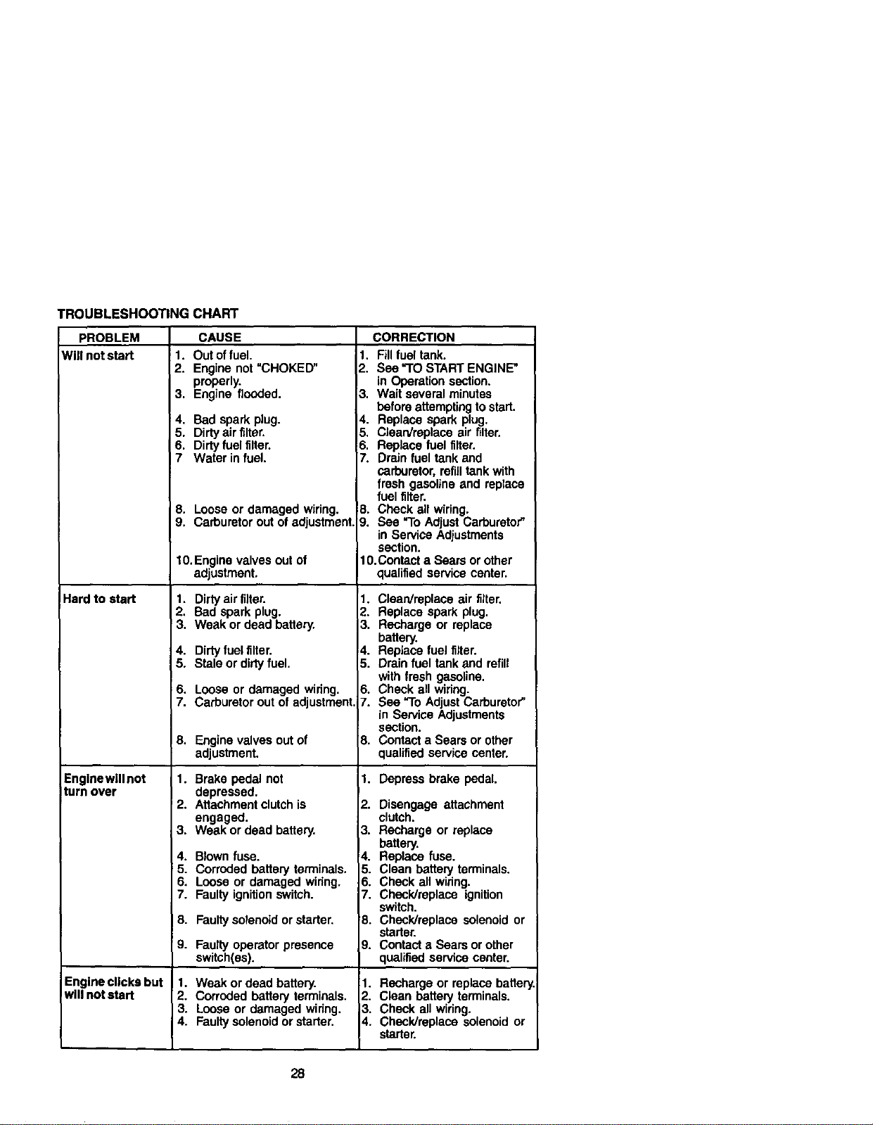
TROUBLESHOOTING CHART
PROBLEM
Willn_s_
Hard to start
Engine will not
turn over
Engine clicks but
will not start
CAUSE CORRECTION
1. Out offuel.
2. Engine not "CHOKED"
properly.
3. Engine flooded.
4. Bad spark plug.
5. Dirty air filter.
6. Dirty fuel filter.
I 7 Water in fuel.
8. Loose or damaged wiring.
9. Carburetor out of adjustment
10.Enginevalvesoutof
adjustment.
1. Dirty air filter.
2. Bad spark plug.
3. Weak or dead battery,
4. Dirty fuelfilter.
5. Stale or dirtyfuel.
6. Loose or damaged wiring.
7. Carburetor out of adjustment,i
8. Engine valves out of
adjustment.
1. Brake pedal not
depressed.
2. Attachment clutch is
engaged.
3. Weak or dead battery.
4. Blown fuse.
5. Corroded battery terminals.
6. Loose or damaged wiring.
7. Faulty ignition switch.
8. Faulty solenoid or starter.
9. Faultyoperatorpresence
switch(as).
1. Weak or dead battery.
2. Corroded battery terminals.
3. Loose or damaged wiring,
4. Faulty solenoid or starter.
1. Fill fuel tank.
2. Sea "TO START ENGINE"
in Operation section.
3, Wait several minutes
before attempting to start.
I Replace spark plug.
41 Clean/replace air filter.
6. Replace fuel filter.
7. Drain fuel tank and
carburetor, refilltank with
fresh gasoline and replace
fuel filter.
B. Check all wiring.
_}. See "1"oAdjust Carburetor"
in Service Adjustments
section.
10.Contact a Sears or other
qualified service center,
1. Clean/replace air filter.
2. Replace spark plug.
3. Recharge or replace
battery.
4. Replace fuel filter.
5. Drain fuel tank and refill
with fresh gasoline,
6. Check all wiring.
7. See "To Adjust Carburetor"
in Service Adjustments
section.
8. Contact a Sears or other
qualified service center.
1. Depress brake pedal.
2. Disengage attachment
clutch.
3. Recharge or replace
battery.
4. Replace fuse.
5. Clean battery terminals.
6. Check all wiring.
7. Check/replace ignition
switch.
8. Check/replace solenoid or
starter.
9. Contact a Sears or other
qualified service center.
1. Recharge or replace batter
2. Clean battery terminals.
3. Check all wiring,
4. Check/replace solenoid or
starter.
28
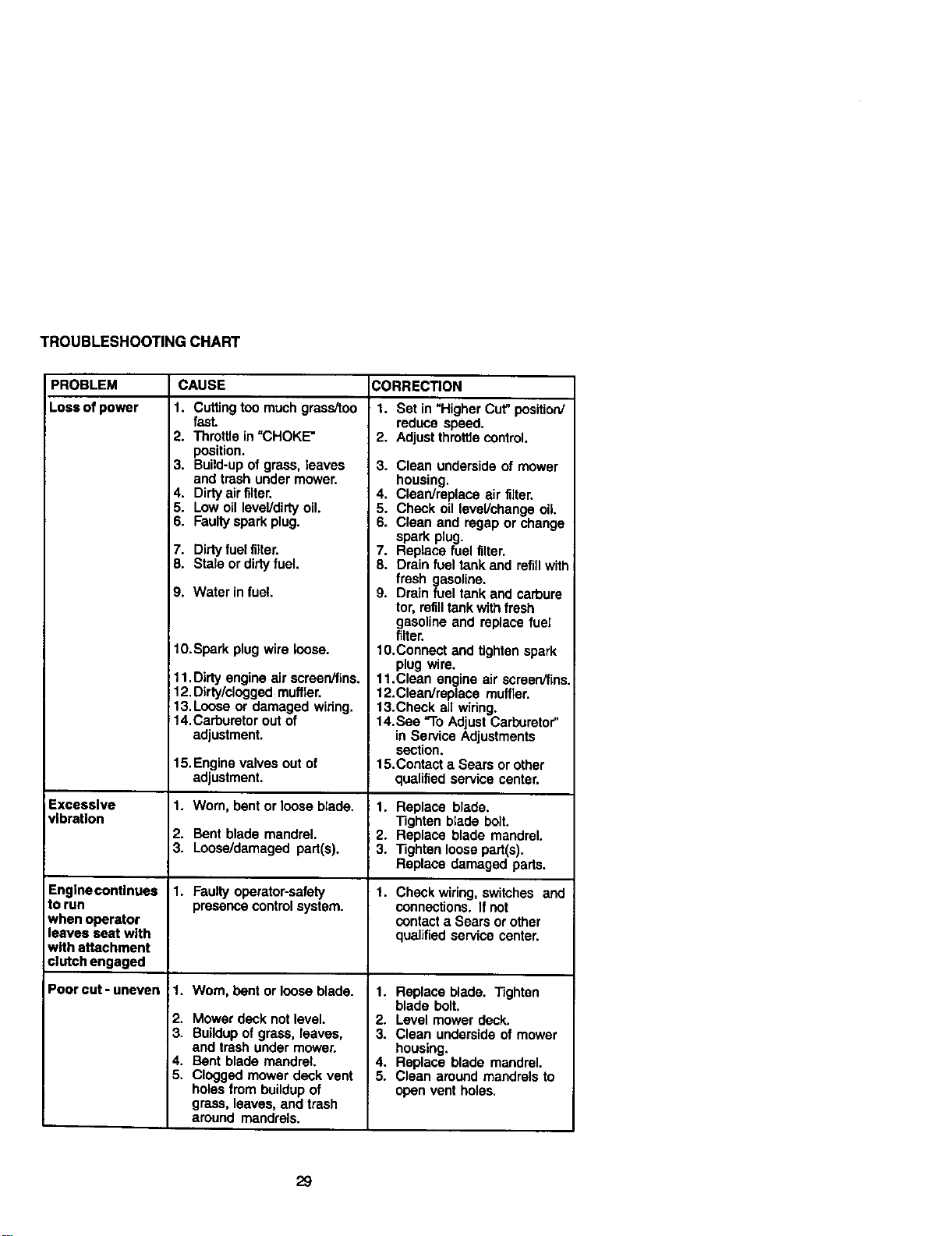
TROUBLESHOOTINGCHART
PROBLEM CAUSE CORRECTION
!Loss of power
Excessive
vibration
Engine continues
to run
when operator
leaves seat with
with attachment
clutch engaged
Poorcut-uneven
1. Cutting too much grass/too
fast.
2. Throttle in =CHOKE"
position.
3. Build-up of grass, leaves
and trash under mower.
4. Dirty air filter.
5. Low oil level/didy oil.
6. Faulty spark plug.
7. Dirty fuelfilter.
8. Stale or dirty fuel.
9. Water in fuel.
10.Spark plug wire loose.
11. Dirty engine air screen/fins.
12. Dirty/clogged muffler.
t 3. Loose or damaged widng.
14.Carburetor out of
adjustment.
15.Enginevalvesoutof
adjustment.
1. Worn, bent or loose blade.
2. Bent blade mandrel.
3. Loose/damaged part(s).
1. Faulty operator-safety
presence control system.
1. Wom, bent or loose blade.
2. Mower deck not level.
3. Buildup of grass, leaves,
and trash under mower.
4. Bent blade mandrel.
5. Clogged mower deck vent
holes from buildup of
grass, leaves, and trash
around mandrels.
1. Set in "Higher Cut" position/
reduce speed.
2. Adjust threttle control.
3. Clean underside of mower
housing.
4. Clean/replace air filter.
5. Check oil level/change oil.
6. Clean and regap or change
spark plug.
7. Replace fuel filter.
8. Drain fuel tank and refillwith
fresh gasoline.
9. Drain fuel tank and carbure
tor, refilltank with fresh
gasoline and replace fuel
filter.
10.Connect and tighten spark
plug wire.
11.Clean engine air screen/fins.
12.Clean/replace muffler.
13.Check all wiring.
14.See "To Adjust Carburetor"
in Service Adjustments
section.
15.Contact a Sears or other
qualified service center.
1. Replace blade.
Tighten blade bolt.
2. Replace blade mandrel.
3. Tighten loose part(s).
Replace damaged pads.
1. Check wiring, switches and
connections. If not
contact a Sears or other
qualified service center.
1. Replace blade. Tighten
blade bolt.
2. Level mower deck.
3. Clean underside of mower
housing.
4. Replace blade mandrel.
5. Clean around mandrels to
open vent holes.
29
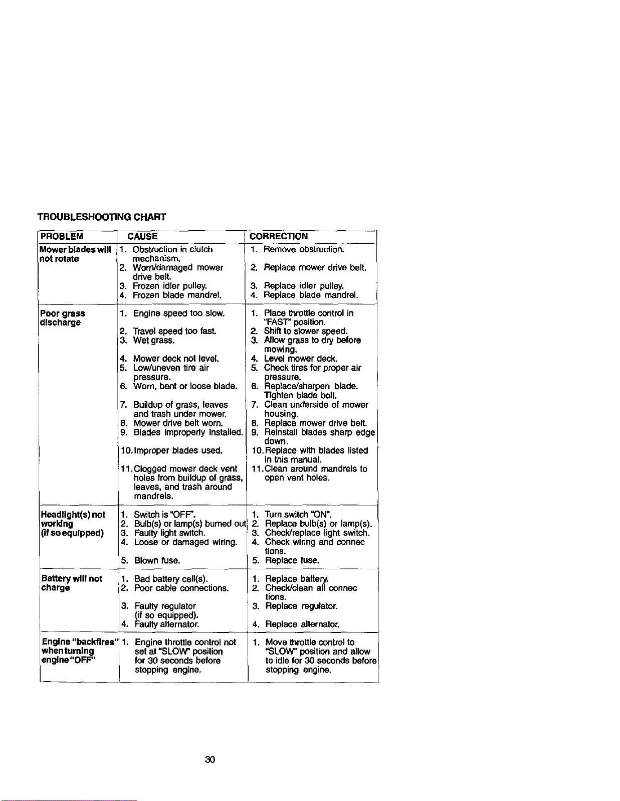
TROUBLESHOOTING CHART
PROBLEM
Mower blades will
notrotate
Poor grass
discharge
Headlight(s) not
working
(ifso equipped)
CAUSE
1. Obstruction in clutch
mechanism.
2. Worn/damaged mower
drive belt.
3. Frozen idler pulley.
4. Frozen blade mandrel
1. Engine speed too slow.
2. Travel speed too fast.
3. Wet grass.
4, Mower deck not level.
5. Low/uneven tire air
pressure.
6. Worn, bent or loose blade.
7. Buildupof grass, leaves
and trash under mower,
8. Mower drive belt worn.
9. Blades improperly installed.
10.Improper blades used.
11. Clogged mower deck vent
holes from buildup of grass,
leaves, and trash around
mandrels.
1, Switch is"OFF".
12. Bulb(s) or lamp(s) burned out
3. Faulty lightsw'_tch.
4. Loose or damaged wiring.
5.
Battery will not 1.
charge 2.
3,
4.
Engine "backfires" 1.
when turning
engine "OFF"
Blown fuse.
Bad battery cell(s).
Poor cable connections.
CORRECTION
1. Remove obstruction.
2. Replace mower drive belt.
3. Replace idler pulley.
4. Replace blade mandrel.
1. Place throttlecontrol in
"FAST"position.
2, Shiftto slower speed.
! 3. Allow grass to dry before
mowing.
! 4. Level mower deck.
5. Check tires for proper air
pressure.
6. Replace/sharpen blade.
Tighten blade belt.
7. Clean underside of mower
housing.
8. Replace mower drive belt.
9. Reinstall blades sharp edge
down.
10.Replace with blades listed
in this manual.
11.Clean around mandrels to
open vent holes.
1. Turn switch"ON',
2. Replace bulb(s) or lamp(s).
3. Check/replace light switch,
4. Check wiring and connec
tions.
5. Replace fuse.
1. Replace battery.
2. Check/clean all connec
tions.
3. Replace regulator.Faulty regulator
(if so equipped).
Faultyalternator. 4. Replace alternator.
Engine throttle control not 1. Move throttle controlto
set at =SLOW" position "SLOW" positionand allow
for 30 seconds before to idlefor 30 seconds before
stopping engine, stopping engine.
30
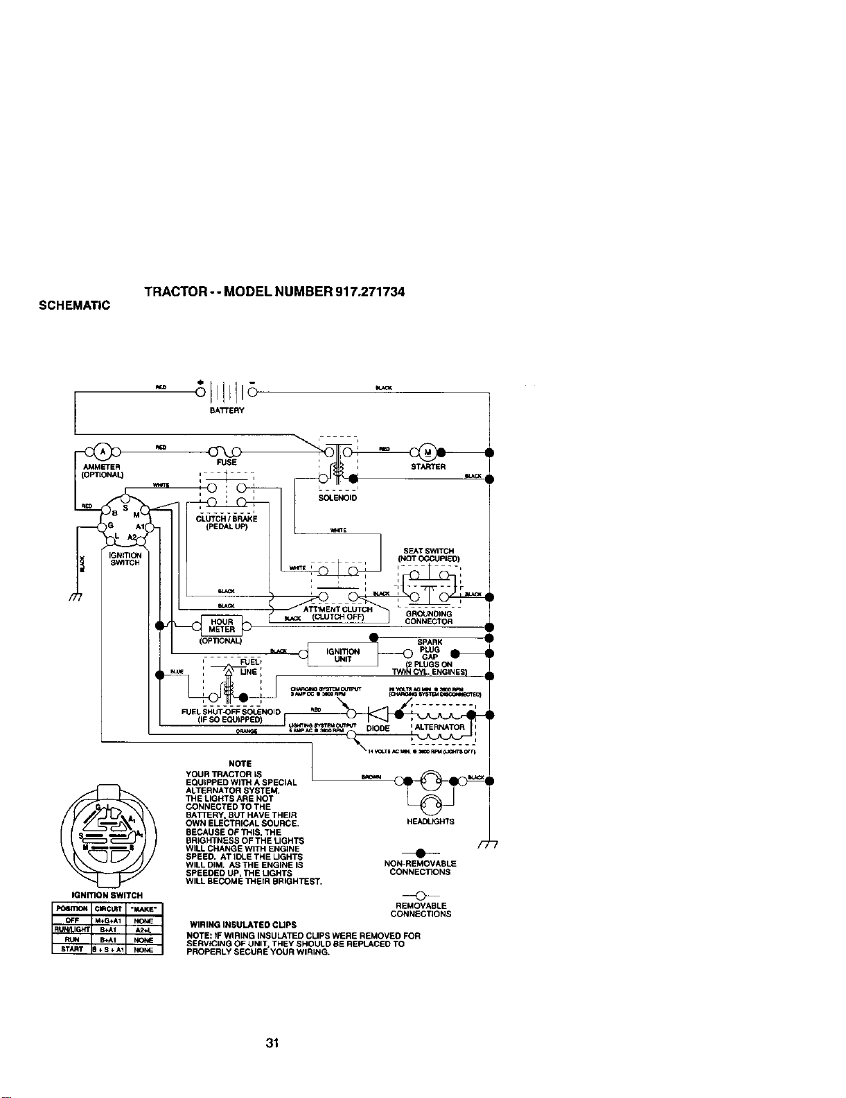
SC_E_A;tC
_p,AcToR" "MODEL RUNI_ER 917.271734
3_
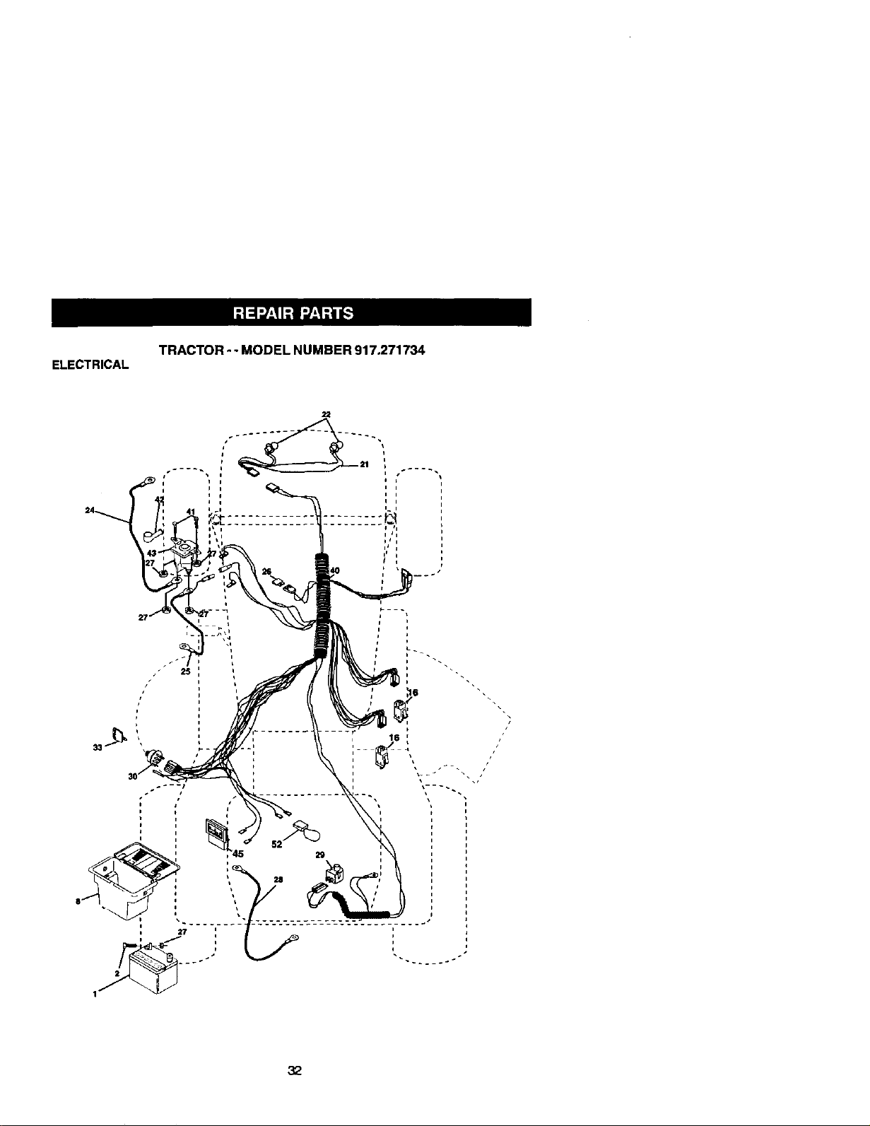
ELECTRICAL
TRACTOR - - MODEL NUMBER 917.271734
i
/
i
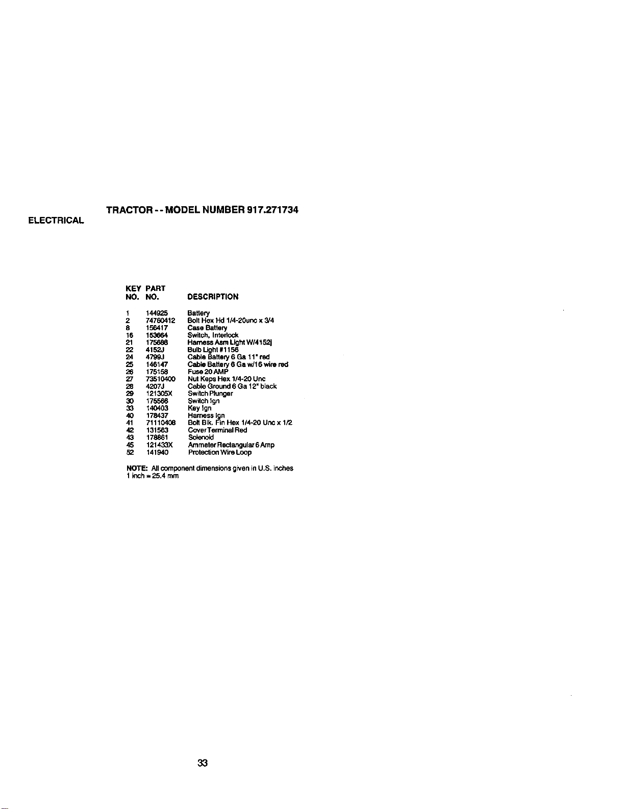
ELECTRICAL
TRACTOR -- MODEL NUMBER 917.271734
KEY PART
NO. NO. DESCRIPTION
1 144925 Battery
2 74760412 Bolt Hex Hd 1/4-20unc x 3/4
8 156417 Case BattePj
16 153_4 Switch, Interlock
21 175688 Harness Asm Light WI4152J
22 4152J Bulb Light #1156
24 4799J Cable Battery 6 Ga 11" red
25 146147 Cabio Battery 6 Ga wll 6 wire red
26 175158 FUSe20AMP
27 73510400 Nut Keps Hex 1/4-20 Unc
28 4207J Cable Ground 6 Ga 12" black
29 1213C5X Switch Plunger
30 175566 Switch Ign
33 140403 Key Ign
40 178437 Harness Ign
41 71110408 BOlt BIk. Fin Hex 1/4-20 Uric x 1/2
42 131563 CoverTerminal Red
43 178861 Bok_noid
45 121433X Ammeter Rectangular 6Amp
52 141940 Protection Wire Loop
NOTE: All component dimensions given in U.S. inches
1 inch = 25.4 mm
33
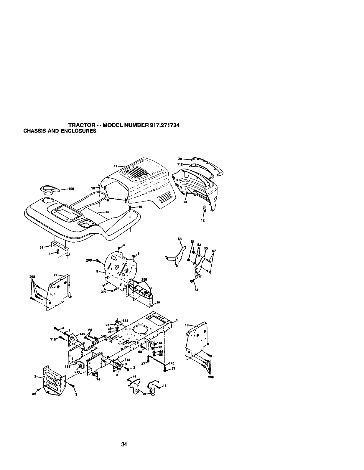
TRACTOR- - MODEL NUMBER 917.271734
CHASSISAND ENCLOSURES
12
f
74
34
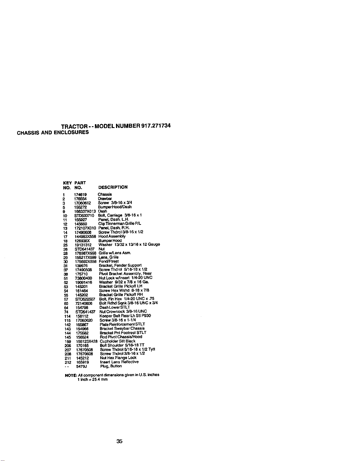
TRACTOR- - MODEL NUMBER 917.271734
CHASSISAND ENCLOSURES
KEY PART
NO, NO, DESCRIPTION
1 174819 Chassis
2 176654 Drawt_er
3 17060612 ,Scn_ 3/8-16 x 3/4
5 155272 Bumper Hood,_ash
9 168337X013 Dash
10 STC_o33710 Bo;t. Carr;uge 3/8.16xl
11 155927 Panel, Dash, LH.
12 145660 Clip Tinnerman Gdlle P/L
13 f72t07X010 Panel, Dash, R.H,
14 17490608 Screw Thdml 3/6-16 x 1/2
17 144983X558 Hood Assembly
18 126938X Bumper Hood
25 19131312 Washer f3/32 x 13/16 x 12 Gauge
26 STD541437 Nut
28 178987X558 Grille w/Lens Asm.
29 155217X599 Lens, Grille
30 175692>:558 Pend_he_st
31 139976 Bracket, Fender"Support
37 174905G6 Screw Thdrol 5/16-18 x 1/2
38 175710 Pivot Bracket Assembly, Rear
51 7"3800400 Nut LockwAnsert 1/4-20 UNC
52 19091416 Washer 9/32 x 7/8 x 16 Ga.
53 14.5201 Bracket Grille Pickoff LH
54 161464 Screw Hex Wshd 6-18 x 7/8
55 14._L_ Bracket Grille Pickoff RH
57 ST0522507 Bolt, FinHex 1/4-20UNCx.75
60 72140606 Bolt Rdhd Sqnk 3/8-16 UNC x 3/4
64 154798 D_sh LowerS1].T
74 $1T_41437 Nut Crown_ock 3/6-16 UNC
114 158112 Keeper Belt Rear Lh Stl P930
115 17060620 Screw 3/6-16 x 1-1/4
142 165867 Plate Reinfomement STLT
143 154966 Bracket Swsybar Chassis
144 1755&2 Bracket Pnt Fcotrest STLT
145 156524 Rod Pivot Chassis/Hood
159 155123X428 CupheiderStltBlack
206 170165 Bolt Shoulder 5/16-18 TI"
207 176705_6 Screw Thdrol 5/16-18 x 1/2 Tytt
2t_ 17670606 Screw Thdrol 3/6-16 x 1/2
211 145212 Nut Hex Flange LOCk
212 165919 Insert Lens Reflective
- - 5479.; Plug, Button
NOTE: Atl (:omponen! riknensions given _nU.S. Jnche.s
1 inch = 25.4 mm
35
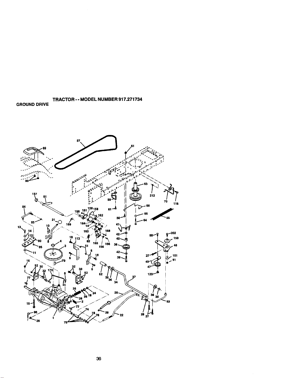
TRACTOR -- MODEL NUMBER 917.271734
GROUNDDRIVE
57
70
116
26
27
36
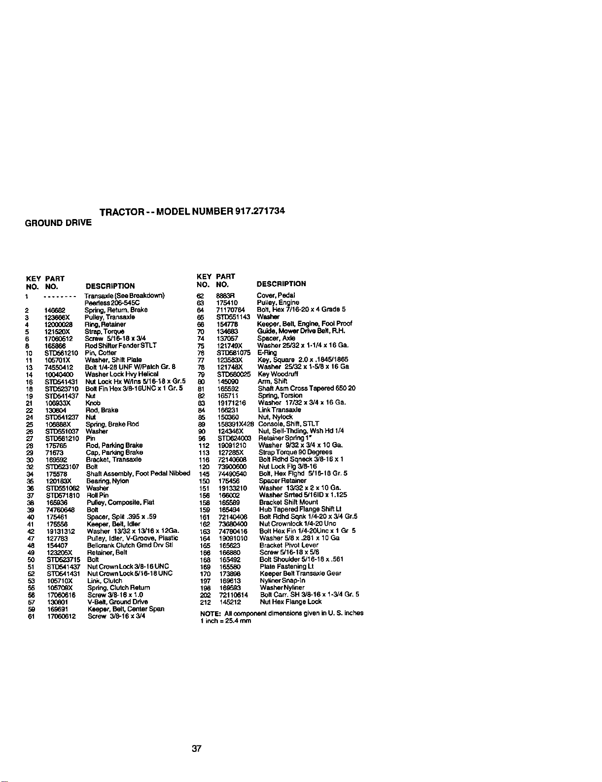
TRACTOR-- MODEL NUMBER 917.271734
GROUNDDRIVE
KEY PART KEY PART
NO. NO. DESCRIPTION NO. NO. DESCRIPTION
1 ........ Transaxle (See Breakdown) 62
peedess 206-545C 63
2 146682 Swing, Return, Brake 64
3 123689X Pulley, Transaxle 65
4 120000_8 Ring,Retainer 66
5 121520X Strap,Torque 70
6 17060512 Screw 5/16-18 x 3/4 74
8 165866 ROdShifter Fender STLT 75
10 STD561210 Pin, Cotter 76
11 1_701X Washer, Shift Plate 77
13 74550412 Belt 1/4-28 UNF W/Patch Gr. 8 78
14 10040400 Washer Lock Hvy Haiical 79
16 S'FD541431 Nut Lock Hx W/Ins 5116-18 x Gr.5 80
18 BTC523710 Bolt FinHex 3/8-16UNC x 1 Gr. 5 81
19 STD541437 Nut 82
21 106933X _ 83
22 130604 Rod, Broke 84
24 B'i_541237 Nut 89
25 106889X Swing, Brake Rod 89
26 SI_551(_7 Washer 90
27 S'1_561210 Rn 89
28 175765 Rod, Parking Brake 112
29 71673 Cap, Paddng Brake 113
30 168592 Bracket, Transaxle 116
32 ST[To23107 Belt 120
34 175578 Shaft Assembly, Foot Poda_Nibhed 145
89 120183X Beadng, Nylon 150
89 STD_51062 Washer 151
37 BTDB71810 RollPin 189
38 165936 Pulley, Composite, Fiat 158
39 74760648 Bolt 159
40 175461 Spacer, Split .395 x .59 161
41 175556 Keeper, Belt, Idler 162
42 19131312 Washer 13/32 x 13/16 x 12Ga. 189
47 127783 Pulley, Idler, V-Groove, Plastic 164
48 154407 Bellcrank Clutch Gmd Dry Stl 165
49 1232GSX Retainer, Belt 166
50 BTD523715 Bolt 168
51 S]_541437 Nut Crown Lock 3/8-16 UNC 169
52 STC541431 Nut C;own Lock 5/16-18 UNC 170
53 105710X Link, Clutch 197
89 1057(_X Swing, Clutch Return 198
89 17060616 Screw 3/8-16 x 1.0 2(_
57 130801 V-Belt, Ground Drive
59 169691 Keeper, Belt, Center Span
61 17060612 Screw 3/8-16 x 3/4
8989R Cover, Pedal
175410 Pulley, Engine
71170764 Bolt, Hex 7/16-20 x 4 Grade 5
BTD891143 Washer
154778 Keeper, Belt, Engine, Fool Proof
134683 Guide, Mower Drive Belt, R.H,
137057 Spacer, Axle
121749X Washer 25132 x 1-1/4 x 16 Ga.
ST[To81075 E-Ring
123583X Key, Square 2.0 x .1845/1865
121748X W_.sher 25/32 x 1-5/8 x 16 Ga
STD589025 Key Woodruff
145090 Ann, Shift
165592 Shaft Asm Cross Tapered 650 20
165711 Swing, Torsion
19171216 Washer 17/32 x 3/4 x 16 Ga.
166231 Link Transaxle
150360 NUt, Nylock
158391X428 Console, Shift, STLT
124346X Nut, Self-Thdin9, Wsh Hd 1/4
STD6240G3 Retainer Spdng 1"
19091210 Washer 9/32 x 3/4 x 10 Ga.
127285X Strap Torque 90 Degrees
72140608 Belt Rdhd Sqneck 3/8-16 x 1
73SC0600 Nut Lock Fig 3/8-16
74490540 Belt, Hex Flghd 5/16-19 Gr. 5
175456 Spacer Retainer
19133210 Washer 13/32 x 2 x 10 Ga.
166002 Washer Srrted 5/161D x 1.125
165589 BraCket Shift Mount
165494 Hub Tapered Range Shift Lt
72140406 Belt Rdhd Sqnk 1/4-20 x 3/4 Gr,5
73680400 Nut Crownlock 1/4-20 Unc
74780416 Bolt Hex Fin 1/4-20Unc x 1 Gr 5
19091010 Washer 5/8 x 281 x 10 Ga
165623 Bracket Pivot Lever
166880 Screw 5/16-18 x 5/8
165492 Bolt Shoulder 5/16-18 x .561
165580 Plate Fastening Lt
173898 Keeper Belt Transaxia Gear
169613 Nyliner Snap-In
169593 Washer Nyliner
72110614 Belt Cart. SH 3/8-16 x 1-3/4 Gr. 5
212 145212 Nut Hex Flange Lock
NOTE: All component dimensions given in U. S. inches
1 inch = 25.4 mm
37
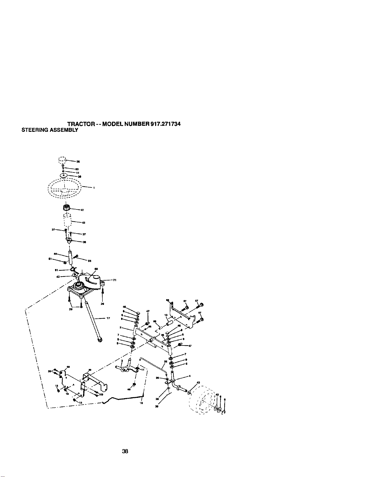
TRACTOR-- MODELNUMBER917.271734
STEERINGASSEMBLY
L
33' '_["
--_:
\
\
38
TRACTOR -- MODEL NUMBER 917.271734
STEERINGASSEMBLY
KEY PART
NO. NO. DESCRiPTiON
1 139768 Steer;ag Wheel
2 154427 AxleAssembly STMP Dropped STL
3 169640 Spindle Assembly, L.H.
4 185e39 Spindle Assembly, R.H.
5 5285H Bearing, Race, Thrust, Hardened
6 121748)( Washer 25/32 x 1-5/8 x 16 Gauge
7 19272016 Washer 27/32 x 1-1/4 x 16 Gauge
8 12850029 Ring. K_ip
9 3366R Beadag. Steedng Column
10 175121 Draglink
11 STITo51137 Wesher, Lock
13 136518 Spacer Beedag Axle Front
15 145212 Nut, Hex Flange Lock
17 177876 Shaft Assembly. Stee_ng
26 126847)( Bushing, Link, Drag
28 19131416 Washer 13/32 x 7/8 x 16 Gauge
29 17(360612 Screw 3/8-16 x 3/4
30 STD561210 pin Cotter
39 130465 Red,]_e
36 155099 Bushing, Steedng
37 152927 Screw
38 139769 Insert. Steedng Wheel
39 19133812 Washer 13/32 x 2-3/8 x 12 Gauge
40 STD541857 NutLockCenter 5/8-24Unf
41 100711L Adaptor, Steedng Wheel
42 145_54X428 Boot, Steedng Sha_
43 121749X Washer 25/32 x 1-1/4 x 15 Gauge
44 153720 Extension Sheft Steering LR.LT
,_ _21239X Cap, Spindis
47 8585M Fitting,Grease
51 STC541431 Nut Lock Hex w/Ins. 5/18-18 UNC
54 74788520 Bolt Fin Hex 5/18-18 UNC x 1-1/4
63 STD523710 Bolt, Fin Hex 3/8-16 UNC x 1Gr 5
85 160367 Spacer Brace AXle
67 72140618 Bolt RDHD Sqnk 5/8-16 x 2-1/4
68 169627 AxIS, Brace
71 175146 Steedng ASm.
82 185835 Bracket Susp. Chassis Front
85 133835 Fastene¢Christmas Tree
85 175118 Bolt Shoulder 7/16-20
91 175553 Clip Steering
NOTE: A_ component dimensions given in U.S. inches
1 inch = 25.4 mm
39
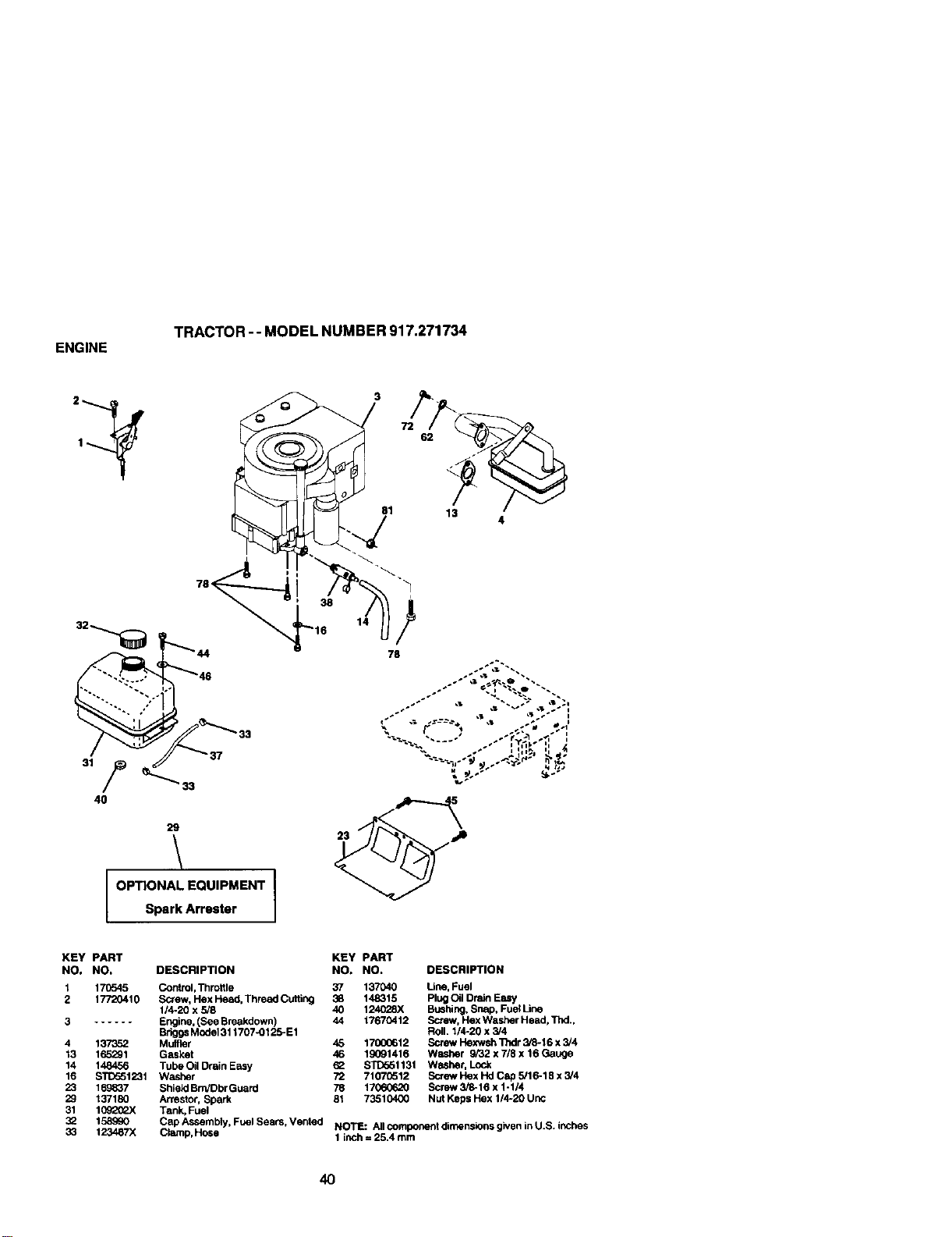
ENGINE
TRACTOR -- MODEL NUMBER 917.271734
81 13
4
29
\
OPTIONAL EQUIPMENT I
Spark Arrester
KEY PART
NO. NO. DESCRIPTION
1 170545 Control,Throttle
2 17720410 Screw, Hex Head. Thread Cutting
1/4-20 x 5/8
3 ...... Engine. (See Breakdown)
BriggsModel 311707K1125-E1
4 137352 Muffler
13 165291 Gasket
14 148456 Tube Oil Drain Easy
16 ST1_51231 Washer
23 16_837 Shield Bm/Dbr Guard
29 137180 Arrestor, Spark
31 1092_.X Tank, Fuel
32 158990
33 123487X
KEY PART
NO. NO. DESCRIPTION
37 137040 Line, Fuel
38 148315 Plug Oil Drain Easy
40 1240_8X Bushing, Snap, Fue_Line
44 17670412 Screw, Hex Washer Heed, Thd.,
Roll. I/4-20 x 3/4
45 17000612 Screw Hexwsh 11_Ir 3/8-I 6 x 3/4
46 19091416 Washer 9/32 x 7/8 x 16 Gauge
62 STD561131 Washer, Lock
72 7107_12 Screw Hex Hd Cap 5/16-18 x :1/4
78 17060620 Screw 3/8-16 x 1-1/4
81 73510400 Nut Keps Hex 1/4-20 Unc
Cap Assembly, Fuel Sears, Vented NOTE: All component dimensions given in U.S. inches
Champ,Ho_e 1 inch = 25.4 mm
4O
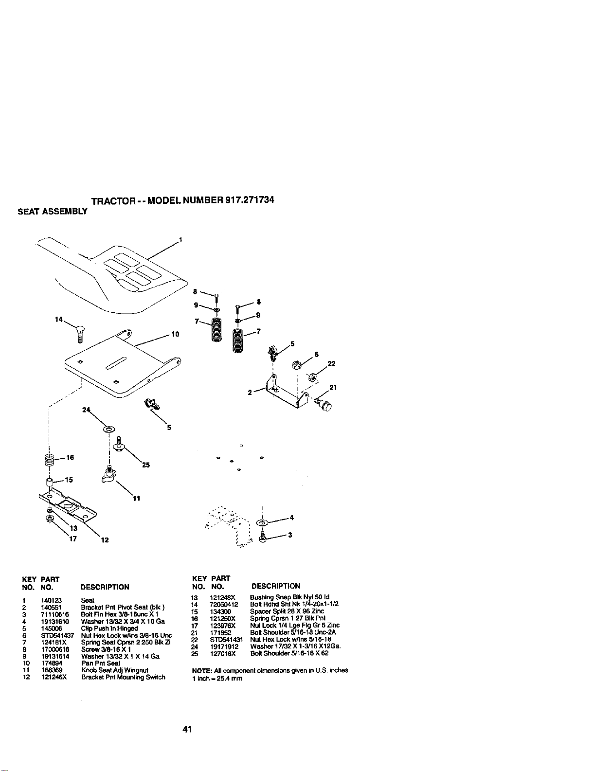
TRACTOR- - MODEL NUMBER 917.271734
SEATASSEMBLY
\
\
/7 5
6
I _ 22
KEY PART
NO. NO, DESCRIPTION
1 140123 Seat
2 140561 Bracket Pnt pivot Seat (blk)
3 71110616 Bolt Fin Hex 3/8-16unc X 1
4 19131610 Washer 13/32 X 5/4 X 10 Ga
5 145006 Clip Push In Hinged
6 STC641437 Nut Hex Lock w/In_ 3/8-16 Unc
7 124181X Spring Seat Cptsn 2 250 BIk Zi
8 17000616 Screw 3/8-16 X 1
9 19131614 Washer 13,'32 X 1X 14 Ga
10 174894 Pan PUt Seat
11 166369 Knob Seat Adj Wingnut
12 121246X Bracket Pnt Mounting Switch
KEY PART
NO, NO. DESCRIPTION
13 121248X Bushing Snap BIk Nyl 50 Id
14 72(TOO412 Bolt RcihdSht Nk 1/4-20x1-1/2
15 134300 Space_ Split 28 X 96 Zinc
16 121250X Spring Cprsn 1 27 BIk PUt
17 123976X Nut Lock 1/4 Lge Fkj Gr 5 Zinc
21 171852 Bolt Shoulder 5/16.18 Unc-2A
22 ST0541431 Nut Hex Lockw/Ins 5/16-18
24 19171912 Washer 17132 X 1-3/16 X12Ga.
25 127018X Bolt Shoulder 5/16.18 X 62
No'rE: All component dimensions given in U.S. inches
1 inch = 25.4 mm
41
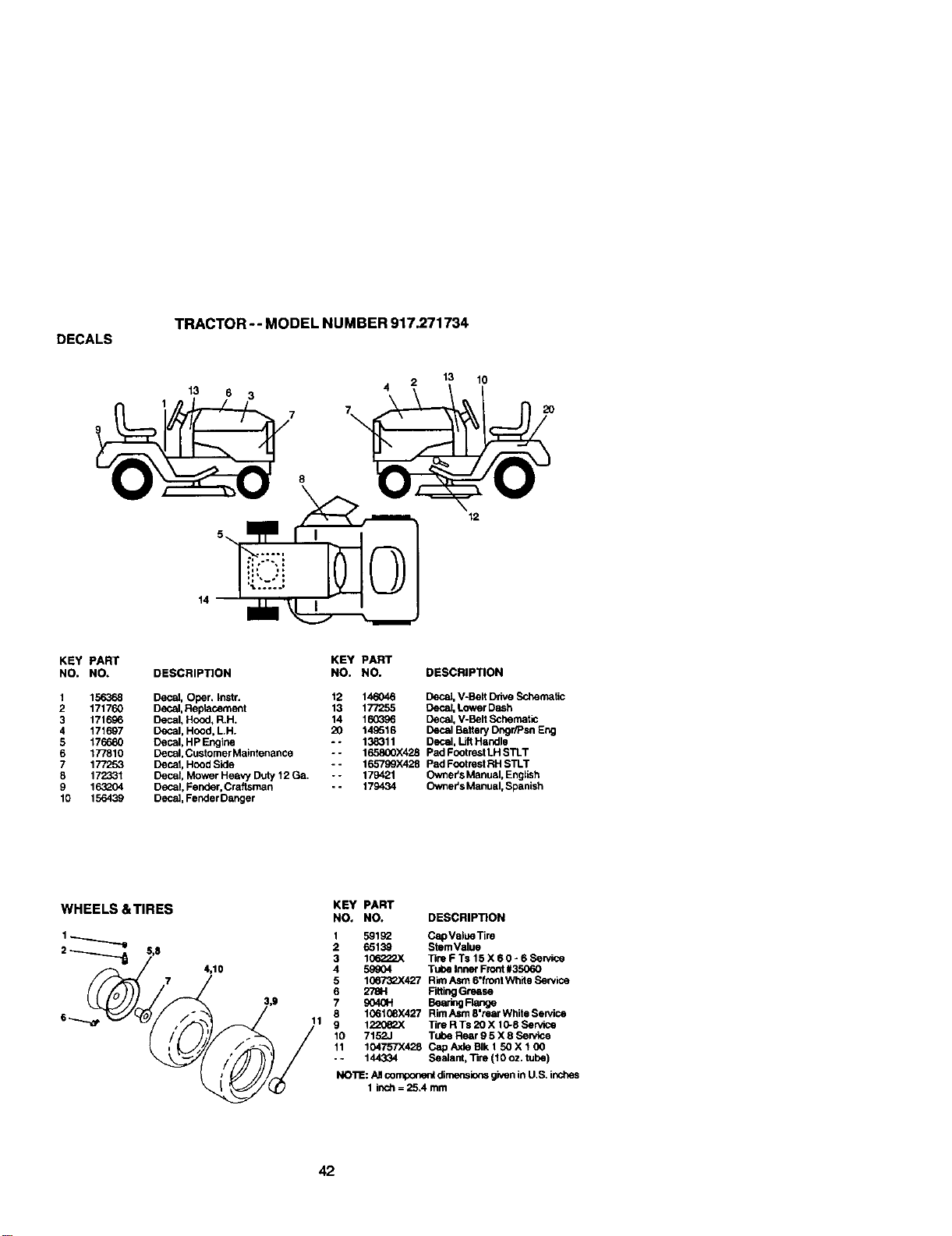
DECALS
TRACTOR -- MODEL NUMBER 917.271734
_7 7_13 6 3 4 2 1! 120
KEY PART KEY PART
NO. NO. DESCRIPTION NO. NO. DESCRIPTION
1 156368
2 171760
3 171696
4 171697
5 176680
6 177810
7 177253
8 172331
9 163_°04
10 156439
Decal, Oper. Instr.
Decal, Replacement
Decal, Hood, R.H.
Decal, Hood, LH.
Decal, HP Engine
Decal, Customer Maintenance
Decal, Hood Side
Decal, Mower Heavy Duty 12 Ga.
Decal, Fender, Craftsman
Decal Fender Danger
12 146046 Decat, V-Belt Drive Schematic
13 177255 Decal, Lower Dash
14 160396 Decal, V-Belt Schematic
20 149516 Decal Battery Dngr/Psn Eng
- - 138311 Decal, LiftHandle
-- 165800X428 Pad Footrest LH STLT
-- 165799X428 Pad Footrest RH STLT
-- 179421 Owner's Manual, Engtish
- - 179434 Ownel's Manual, Spanish
WHEELS &TIRES
4,10
KEY PART
NO. NO. DESCRIPTION
1 59192 Cap Value Tim
2 6513_ StemValue
3 106222X ]]m F Ts 15 X 6 0 - 6 ScP/ice
4 59_04 Tube Inner Front#35060
5 106_427 Rim Asrn 6"frontWlYdeService
6 2781-1 Fdting Grease
7 9040H Bearing Flange
8 1061(_X427 RimAsm 8"rear White Service
11 9 1220_.X Tire R Ts 20 X 10-8 Service
10 7152J Tube Rear 9 5 X 8 Sewlce
11 104757X428 Cap Axle BIk 1 50 X 1 00
- - 144334 Sealant, Tire (10 oz. tube)
NO'RE:AJIcompone_ dimensions givenin U.S. inches
1 inch = 25.4 mm
42
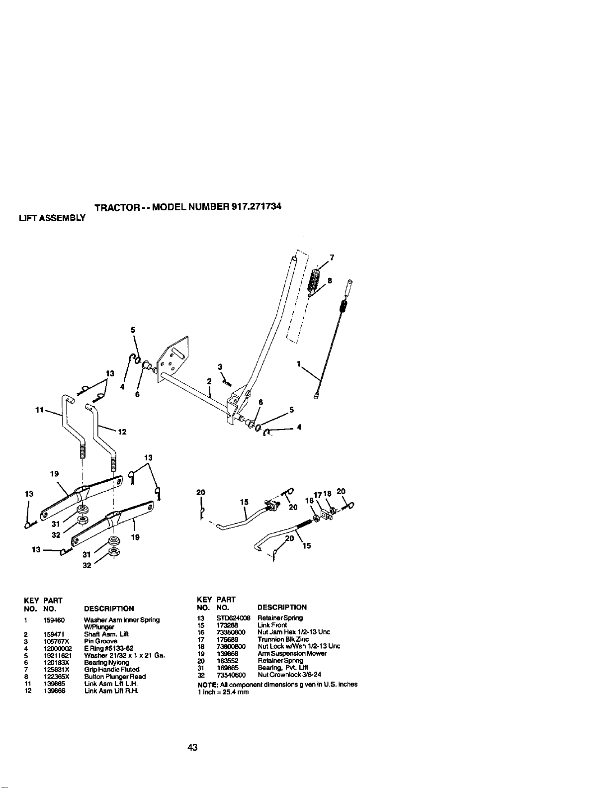
TRACTOR- - MODEL NUMBER 917o271734
LIFTASSEMBLY
13
19
13
32
19
13
15
2O
KEY PART
NO. NO. DESCRIP'nON
1 159460 Washer Asm Inner $pdng
W,_nger
2 159471 Shaft Asm. Lift
3 1G5767X Pin Groove
4 120000_ E Ring #5133-62
5 lg211621 Washer 21/32 x 1 x 21 Ga.
6 120183X Besting Nylong
7 125631X Grip Handle Fluted
5 122365)( Button Plunger Read
11 139665 Link Asrn Lilt L.H.
12 139666 Link Asm Lift R,H,
KEY PART
NO. NO. DESCRIPTION
13 S'[D_40(_ Retainer Sp_lng
15 173288 Unk Front
16 73350800 Nut Jam Hex I/2-13 Unc
17 175689 Trunnlon Blk2_nc
18 73800800 Nut Lock w/Wsh I/2-13 Uric
19 13_68 ArmSuspensk>nMower
20 163552 Retainer Spnng
31 169665 Sharing, Pvt. Lift
32 73540600 Nut Crownlock 3/8-24
NOTE: All component dimensions given in U.S. inches
I inch = 25.4 mm
43
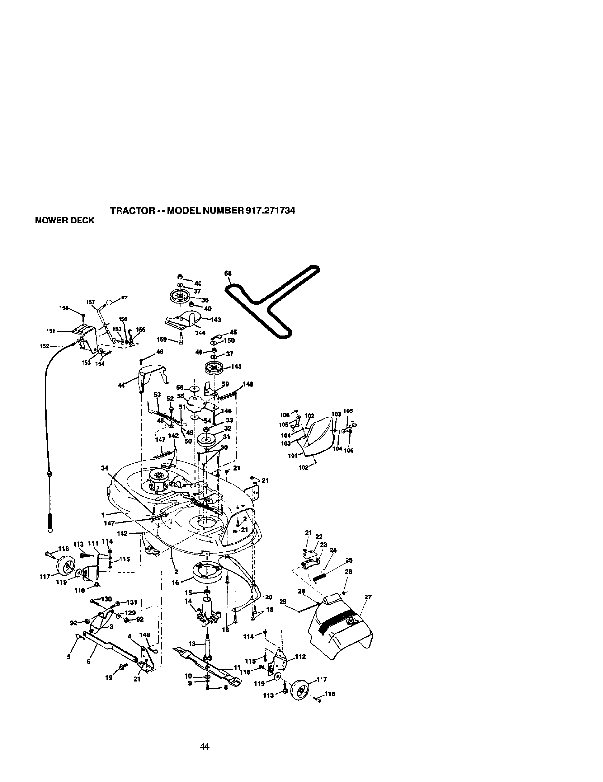
TRACTOR--MODELNUMBER917.271734
MOWERDECK
44
TRACTOR-- MODEL NUMBER 917.271734
MOWERDECK
KEY PART KEY PART
NO. NO. DESCRIPTION NO. NO. DESCRIPTION
1 1658S_ Mower Housing 56 165723 Spacer, Retainer
2 STC533107 Bolt 59 141043 Guard, Tuv Idler (94)
3 138017 Bracket Assembly,Sway Bar, 67 14g_46 Knob Custom Oval
Front 68 144959 V-Bolt
4 165460 Bracket Sway Bar 35/42" 92 STCro41437 Locknut, Hex W/Wsh 3/8-16 UNC
5 _4008 RetainerSprtng 101 136420 CoverMuP..hing42"Btack
6 1_ Arm, Suspension, Rear 1C2 71081010 Screw Truss Hd Phil10-24 x5/8
8 850857 Bolt, Hex 3/8-24 x 1.25 Gr. 8 103 19061216 WBsher#10
9 STD55113"/ Washer, L(:ck 104 STD551110 WasherLock
10 14G296 Washer, Hardened 1_6 160793 Lutch Asm Bagger
11 134149 Blade, Mulching 106 2029J NutWeld
13 137645 Sha_ Assembly, Mandrel, Vented 111 174525 Bracket Gauge, Wheel LH
(IncL Key Number 6) 112 174.q_6 Bracket, Gauge, Wheel RH
14 128774 Housing.Mandrel, Vented 113 17060512 Screw 5116-18x3/4
15 110485X Bearing, Bali, Mandrel 114 73510500 Nut, HexKeps 5/16-18UNC
16 174493 Stripper, Mower Deck 115 72110504 BoR,Carriage 5/16 UNC x 1/2
18 72"i405C5 Bolt, Caniage 5/10-18 x 5/8 116 4898H Bolt. Shoulder
19 132827 Bolt, Shoutder 117 165746 Wl_ee],Gauge
20 159770 Baffle, Vortex 118 73930600 Nut, Crownlock 3/8-1
21 STD541431 Nut,Crownloc_<5i16-18UNC 119 19121414 Washer 13/32 x 7/8 x 14 Ga.
22 134753 Stiffener Bracket 129 19131312 Washer 13/32 x 15/16 x 12 Ga.
23 131267 Bracket, Deflector 130 STC523710 Sclt, Fin Hex 3/8-16 UNC x 1 Gr 5
24 105304X Cap, Sleeve 131 STD533710 Bolt Rdhd Sqnk 3/8-16 UNC x 1
25 123713X Spring, Torsion, De flector 142 165890 Ann Spffeg Brake Mower
26 110452X Nut, Push 143 157109 Bracket Arm ldier 42"
27 130968X428 Shield, Deflector 144 158634 KeeparBolt42"ClutchCab_e
28 19111016 Washer 11/32 x 5/8 x 16 Ga. 145 165888 Pulley Idler Flat
29 131491 Red.Hinge 146 171977 BOlt Carraige Idler
30 157722 Screw "rhdrolRollingWsh Hd 147 131335 Spring Extension
31 129963 Wasffer, Spacar 148 169(_2 Spring Return Idler
32 153535 Pulley, Mandrel 149 165898 Retainer Spring Yelldw Zinc
33 178342 Nut,Topldck, Flanged 150 19091216 Washer 9/32 x 3/4 x 16 Ga.
34 ST[To33717 Bolt 151 169670 Bracket Clutch
36 131494 Pulley, Idler, Fkzt 152 169676 Cable CLutch42"
37 19131316 Washer13,'32x13/16x16Ga. 153 169674 Washerffet 3/8"TypeB
40 STD541437 Nut, Crownlock3i8-16UNC 154 169675 SpringRetainer
44 140088 Guard, Mandrel, L.H. 155 169671 Spring Retention Lever
45 ST[To24(_3 RetaJner 156 169672 Spacer
46 137729 Screw, Thd. Rotl t/4-20 x 5/8 157 169669 RedClutch
48 133944 Washer, Hardened 158 17720410 Screw Hex Thd Cut 1/4-20 x 5/8
49 174284 RollerAssembly. Cam Follower 159 $11To33717 Bolt Rdhd Sqn 3/8-16 uric x 1-3/4
50 131340 Bolt, Shoukler #10-24 Grade 5 -- 130794 Mandrel Assemb;y (Incl_les Key
51 S'rD541410 Locknut Numbers 8-10, 13-15, 31 and 32)
52 139888 Bolt, Shoulder 5/16-18 UNC - - 169583 Replacement Mower, C_xnplete
53 131845 Arm Assembly, Pad, Brake
54 133943 Washer, Hardened NOTE: _t component dimensions given inU.S. inches
55 155046 Arrn, Idier 1 inch --25.4 mm
45
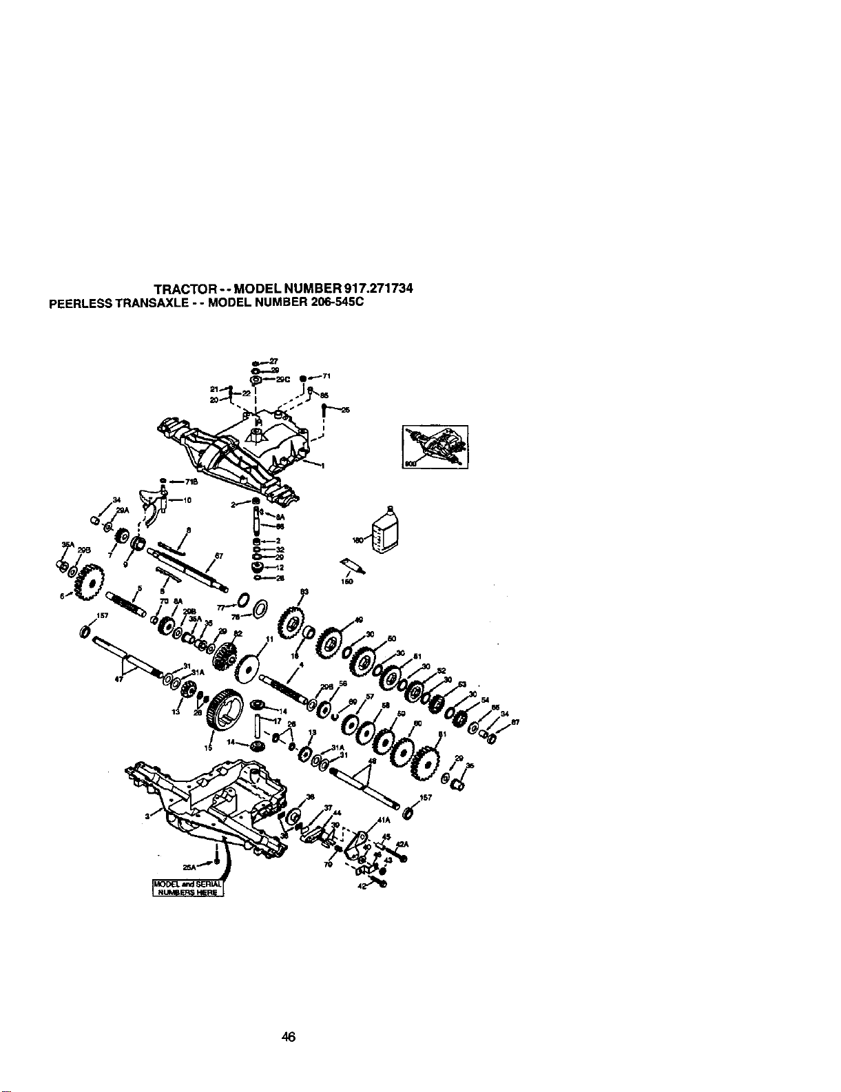
TRACTOR- - MODEL NUMBER 917.271734
PEERLESSTRANSAXLE-- MODELNUMBER206-545C
157
47
34
41A 157
46

TRACTOR-- MODEL NUMBER 917.271734
PEERLESSTRANSAXLE- - MODELNUMBER206-545C
KEY PART KEY PART
NO. NO, DESCRIPTION NO* NO. DESCRIPTION
1 772147 TransexioCover 41A 790079 Brake Lever
2 780086A Needle Beadng 5/6. 42 792073A Screw 1/4 - 20 x 1-1/4"
3 770128 Transa.xleCase 42A 7_ Screw 1/4 - 20 x 2 1/4"
4 776395 Countershaft 43 792075 Lock.nut5 / 16 - 24
5 7764C9 Output Shaft 44 790925 Brake Pad Holder
6 778364 Spur Gear (38 teeth) 45 786066 Spacer .2625 x 1.0
6A 778369 Sptx Gear (15 teeth) 46 786C86 Sntke Lever Bracket
7 778330 Spur Gear (11 teeth) 47 774690 Aide (11-15 / 16. Long)
8 792180 Shlft Key 48 774691 Axle (16 - 1 / 2" iong)
8A 792047 Woodruff Key #9 49 778356 Spur Gear (29 teeth)
9 784.352 Shift Collar 50 778338 Spur Gear (27 teeth)
10 784378 Shift Red & Fork 51 778354 Spur Gear (23 teeth)
11 778334 Beval Gear (30 teeth) 52 778352 Spur Gear (19 teeth)
12 778309 InputBevel Pinion (13 teeth) 53 778350 Spur Gear (16 teeth)
13 778368 Bevel Gear (13 taeth)(Include. 14) 54 778346 Spur Gear (15 teeth)
14 778368 Bevel Pin!on (13 taeth)(Inclede. 13) 56 778355 Spur Gear (11 taeth)
15 778370 Ring Gear (43 teeth) 57 778337 Spur Gear (13 teeth)
17 786188 Drive Pin 58 778353 Spur Gear (17 teeth)
18 786102 Spacer 1.130 X .695 59 778351 Spur Gear (21 teeth)
20 792077A Ball 5/16. dia 60 778349 Spur Gear (24 teeth)
21 792078 Set Screw 3/8 - 16 x 3/8" 61 778345 Spur Gear (25 teeth)
22 792079 Spring .310 OD x ,625 L 65 780189 Flat Washer .563 ID x .062W
25 792073A Screw 1/4 - 20 x 1-1/4" 66 776422 Input Shaft
25A 792177 Screw 1/4-20 x 1-3/8" 67 77_96 Shifter & Brake Shaft
26 792125 Retaining Ring (pkg of 2) 69 792170 Retaining Ring
27 792035 RetainingRing 70 786187 Spacer .8_K)
28 788040 RetainingRing 71 788069 Square CUt Ring
29 78_072 3"_,rustWasher .627 ID x.031W 71B 788092 "O"Ring
29A 780160 Thrust Washar .762 ID x.031W 76 780090 Flat Washer 1.128 ID x .058W
29B 780051 Thrust Washar .762 ID x.031W 77 788078A thverted Retaining R_g
29C 780199 Anti-Rotation Washer .632 79 792144 Spdng .430 OD x .5000 L
30 780106 Cup Washar 1.127 IDx .032W 92 778333 Beval & Spur Gear (30 & 13 taeth)
31 780001 Rat Washer .750 tO x ,056W 83 778338 Spur Gear (27 teeth)
(Use AS Needed) 85 792154 Oil Fill Plug
31A 780195 Rat Washer .750 ID x .062W 87 788089A Oil Seal 9 / 16"
32 788083 Oil Seal 5/6" 150 _ LiquidGasket RTV Silicone
34 780194 Bushing .563 157 788088A Oil Seal 3/4"
35 780193 Flanged Bushing 518" IO 180 _A Gear Oil80W90
35A 780197 FiongedBushing.751 9(X) 794712 ReplacementMST-206-545C
36 79_075 Brake Disk Ttansaxio
37 790007 Brake Pad Ptata
38 79_021 Brake Pad (pkg of 2) NOTE: All component dimensions given in U.S. inches
39 786_26 DowsePin 1 inch = 25.4 mm
40 792076A Flat Washer .312 ID x .059W
47
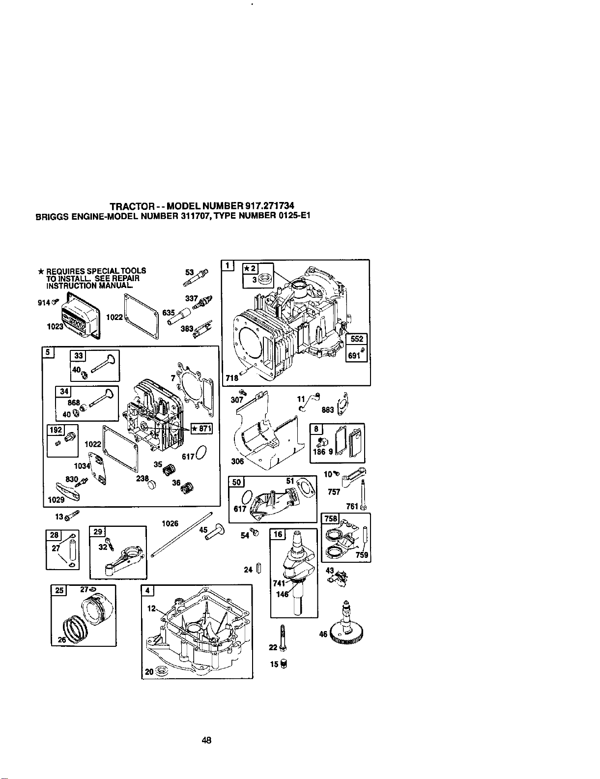
TRACTOR--MODELNUMBER917.271734
BRIGGSENGINE-MODELNUMBER311707,TYPENUMBER0125-E1
-k REQUIRES SPECIAL TOOLS 53_
TO INSTALL SEE REPAIR
INSTRUCTION MANUAL
lO,,_-_j ,.J
617
48
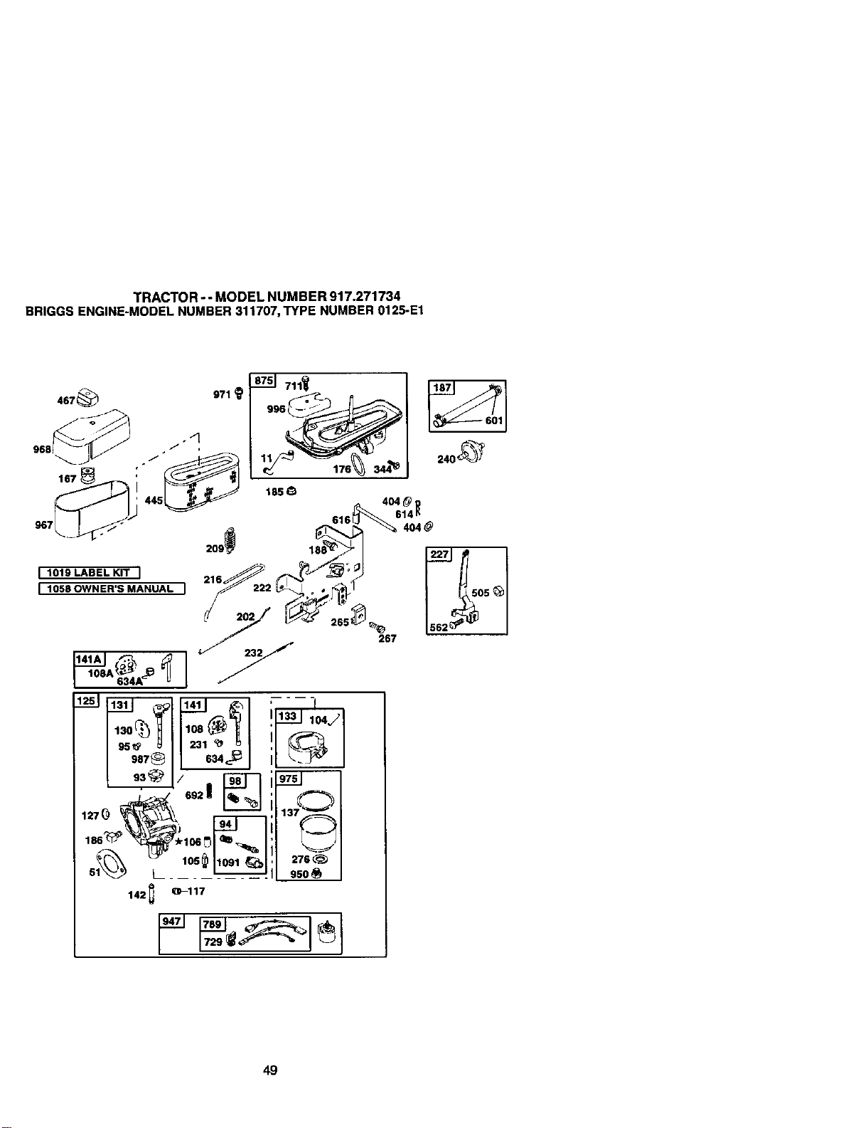
TRACTOR--MODELNUMBER917.271734
BRIGGSENGINE-MODELNUMBER311707,TYPENUMBER0125-E1
4s7_ 971
8751 711_
996_
185_
267
49
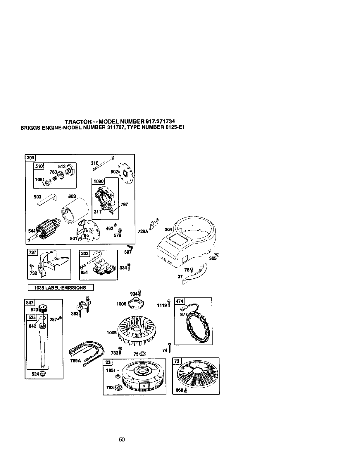
TRACTOR-- MODEL NUMBER 917.271734
BR|GGSENGINE-MODELNUMBER311707,TYPE NUMBER0125-E1
513_%
7_
310
462_
579
80"
,797
1006
5O
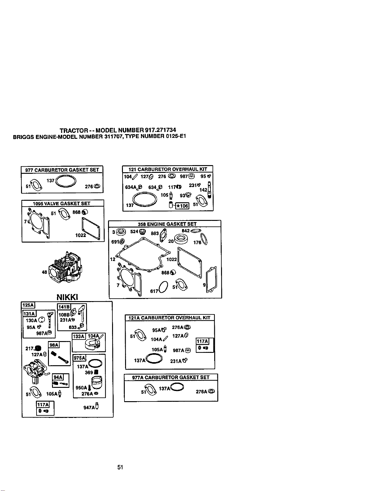
TRACTOR -- MODEL NUMBER 917.271734
BRIGGSENGINE-MODELNUMBER311707,TYPE NUMBER0125-E1
977 CARBURETOR GASKET SET
I 51% 1370 276_
1095 VALVE GASKET SET
7_----_v_ _ 1022_
NIKKI
_TA_][ .3=e
121 CARBURETOR OVERHAUL KIT
lO4_ 1_70 270_ 987@ 99_
634AJ_ 634_._ 1170 2310
950E.GI.EGASKetSET
3_ 5=4@ 005 84_
17o
121A CARBURETOR OVERHAUL KIT
95A_ 276A_
Sl_ I04A_ 127A#
IO5A_057A÷
137A O 231A_P
977A CARBURETOR GASKET SET
51_ 137A_ 276A_
51
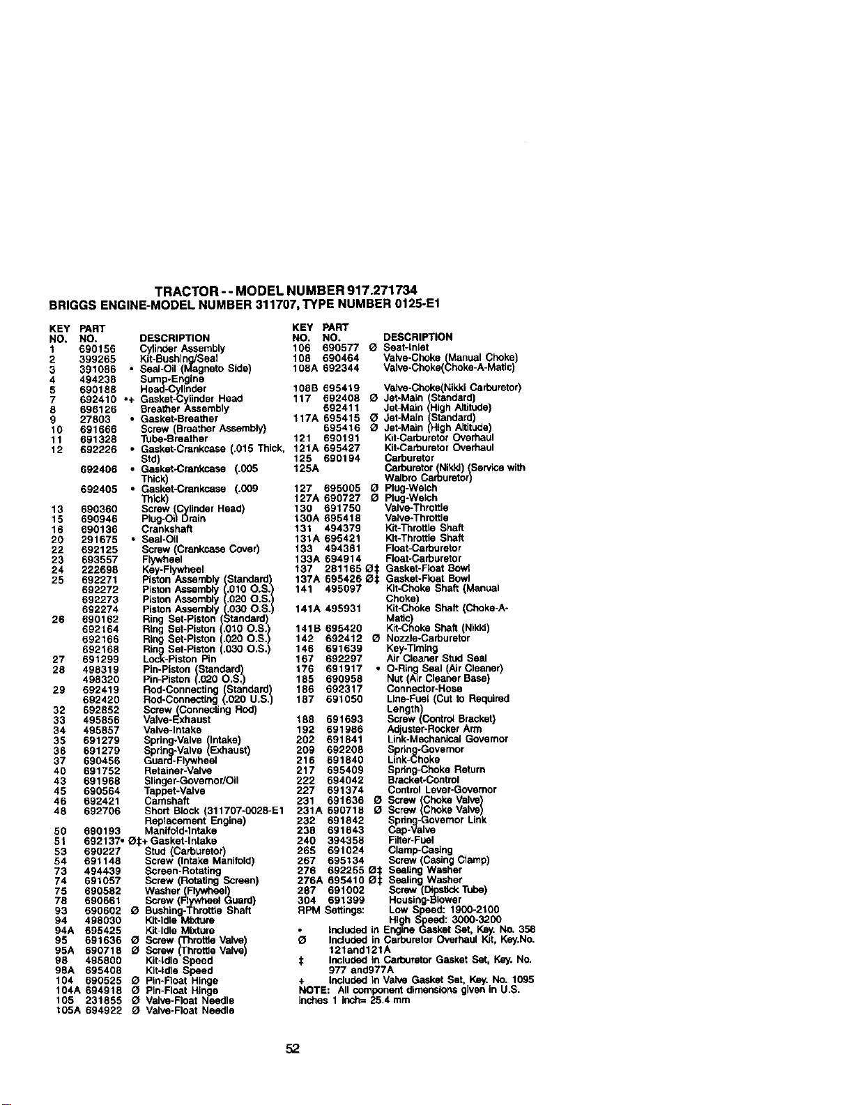
TRACTOR-- MODEL NUMBER 917.271734
BRIGGSENGINE-MODELNUMBER311707,TYPE NUMBER0125-E1
KEY PART KEY PART
NO. NO. DESCRIPTION NO. NO. DESCRIPTION
1 690156 (_tlinder Assembly 106 690577 O Seat-Inlet
2 399265 Kit-Bushing/Seal 108 690464 Valve-Choke(Manual Choke
3 391086 • Seal-Oil (Magneto Side) 108A 692344 Valve-Choke(Choke-A-Matic
4 494238 Sumlp-LF-Engine
5 690188 _-Cyllnder 108B 695419 Valve-Choke(NikkiCarburetor)
7 892410 • Hea
+ Gasket-Cylinder Head 117 692408 O Jet-Main (Standard)
8 696126 Breather Assembly 692411 Jet-Main (High Altitude)
27803 • Gasket-Breather 117A 695415 O Jet-Main(Standard)
0 691666 Screw (Breather Assembly) 695416 G Jet-Main (High Altitude)
11 691328 Tube-Breather 121 690191 Kit-CarburetorOverhaul
12 692226 • Gasket-Crankcase (.015 Thick, 121A 695427 Kit-CarburetorOverhaul
Std) 125 690194 Carburetor
692406 • Gasket-Crankcase (.005 125A Carbumtor(Nitdd)(Service with
Thick) Walbro Carburetor)
692405 ° Gasket-Crankcase (.009 127 695005 _ Plug-Welch
ThP...k) 127A 690727 O Plug-Walch
13 690360 Screw (Cylinder Head) 130 691750 Valve-Throttle
15 690948 Plug-Oil Drain 130A 695418 Valve-Throttle
16 690136 Crankshaft 131 494379 Kit-ThrottleShaft
20 291675 • Seal-Oil 131A 695421 Kit-Throttle Shaft
22 692125 Screw (Crankcase Cover) 133 494381 Float-Carburetor
23 693557 Flywheel 133A 694914 Float-Carburetor
24 222698 Key-Flywheel 137 281165 O_ Gasket-Ftoat Bowl
25 692271 Piston Assembly (Standard) 137A 695426 IZII: Gasket-Roat Bowl
692272 Piston Assembly (.010 O.S.) 141 495097 Kit-Choke Shaft (Manual
692273 P_stonAssembly (.020 O.S.) Choke)
692274 Piston Assembly (.030 O.S.) 141A 495931 Kit-Choke Shaft (Choke-A-
26 690162 Ring Set-Piston (Standard) Mati ;)
692164 / ! 141B
Ring Set-Piston .010 O.S. 695420 Klt-C oke Shaft (Nikki)
h
692166 Ring Set-Piston .020 O.S. 142 692412 _ Nozzle-Carburetor
692168 Ring Set-Piston .030 O.S. 146 691639 Key-Timing
27 691299 Lock-Piston Pin 167 692297 Air Cleaner Stud Seal
28 498319 Pin-Piston (Standard) 176 691917 • O-Ri_. Seal (Air Cleaner)
498320 Pin-Piston (.020 O.S.) 185 690958 Nut (A=rCleaner Base)
29 692419 Rod-Connecting (Standard) 186 692317 Connector-Hose
692420 Rod-Connecting (.020 U.S.) 187 691050 Line-Fuel (Cut to Required
32 692852 Screw(Connec_ng Rod) Length,
33 495856 Valve-Exhaust 188 691693 Screw (Controt Bracket)
34 495857 Valve-Intake 192 691986 Adjuster-RockerArm
35 691279 Spring-Valve (Intake) 202 691841 Link-Mechanical Govemor
36 691279 Spring-Valve (Exhaust) 209 692208 Spring-Governor
37 690456 Guard-Flywheal 218 691840 Link-Choke
40 691752 Retainer-Valve 217 695409 Spring_:hoke Return
43 691968 Slinger-Governor/Oil 222 694042 Bracket-Control
45 690564 Tappet-Valve 227 691374 Control Lever-Governor
46 692421 Camshaft 231 691636 O Screw (Choke Valve)
48 692708 Short Block (311707-0028-E1 231A 890718 _ Screw (ChokeValve)
Replacement Engine) 232 691842 Spdn_g-GovemorLink
50 690193 Manifold-Intake 238 691843 Cap-Valve
51 692137, _1:+ Gasket-Intake 240 394358 Filter-Fuel
53 690227 Stud (Carburetor) 265 691024 Clamp-Casing
54 691148 Screw (Intake Manifold) 267 695134 Screw (Casing Clamp)
73 494439 Screen-Rotating 276 692255 Ot Sealing Washer
74 691057 Screw (Rotating Screen) 276A 695410 O_: Sealing Washer
75 690582 Washer(Flywheel) 287 691002 Screw (DipstickTube)
78 690661 Screw (Rywheel Guard) 304 691399 Housing-Blower
93 690602 _ Bushing-ThrotSeShaft RPM Settings: Low S_<_d: 1900-2100
94 498030 Kit-Idle Mixture High Speed: 3000-3200
94A 695425 Kit-Idle Mixture • Included in Engine Gasket Set, Key. No_358
0 Includedin Carburetor Overhaul Kit, Key.No.95 691636 a Screw (Throtke Valve)
95A 690718 O Screw (Th)rotSeValve 121and121A
98 495800 Kit-Idle Speed t Includedin Carburetor Gasket Set, Key.No.
98A 695408 Kit-Idle Speed 977 and977A
104 690525 O Pin*Roar Hinge + IncludedIn Valve Gasket Set, Key. No. 1095
104A 694918 _l Pin-Float Hing<a NOTE: All componentdimensionsgiven in U.S.
105 231855 (_ Valve-Float Needle inches 1 inch= 25.4 mm
105A 694922 O Valve-Float Needle
52
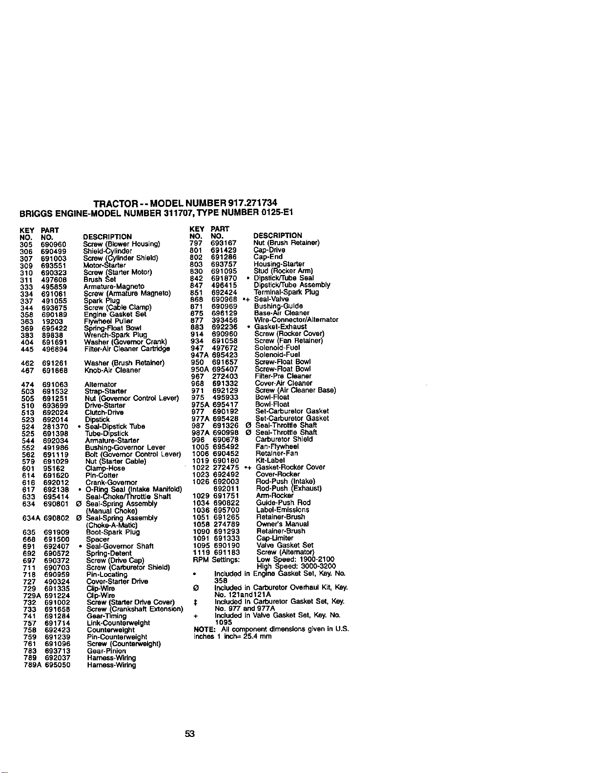
TRACTOR-- MODEL NUMBER 917.271734
BRIGGSENGINE-MODELNUMBER311707,TYPE NUMBER0125-E1
KEY PART
NO. NO. DESCRIPTION
305 690960 Screw (BlowerHousing)
306 690499 Shiald-.Cylilinder
307 691003 Screw(Cylinder Shield)
309 693551 Motor-Starter
310 690323 Screw (Starter Motor)
311 497608 Brush Set
333 495859 Armature-Magneto
334 691061 Screw (Armature Magneto)
337 491055 Spark PluJg
344 693675 Screw (Cable Clamp)
358 690189 Engine Gasket Set
363 19203 Flywheel Pulior
369 695422 _pSdng-FloatBowl
383 89838 Wrench-Spark Plug
404 691691 Wssher Governor Crank)
445 496894 Fiiter-Ar Ceaner Cartndpa
462 691261 Washer (Brush Retainer)
467 691668 Knab-AIr Cleaner
474 691063 Alternator
503 691532 Strap-Starter
505 691251 Nut (GovernorControl Lever)
510 693699 Drive-Starter
513 692024 Clutch-Drlve
523 692014 Dipstick
524 281370 • Seal-DipstickTube
525 691398 Tube-Dipstick
544 692034 Armature-Starter
552 491986 Bushing-GovernorLever
562 691119 Bolt (Governor ControlLever)
579 691029 Nut (Starter Cable)
601 95162 Clam -Hose
614 691620 Pin-_'_tter
616 692012 Crank-Governor
617 692138 • O-Ring Seal(Intake Manifold)
633 695414 Seal-Choke/Throttle Shaft
634 690801 _ SeaI-Sprlng Assembly
(Manual Choke)
634A 690502 _ Seal-Spring Assembly
_Choke-A-Mat_
635 691909 Boot-Spark Pug
668 691500 Spacer
691 692407 • Seal-Governor Shaft
692 690572 Spdng-Detant
697 690372 Screw (Drive Cap)
711 690703 Screw (Carburetor Shio_d)
718 690959 Pin-Locating
727 490324 Cover-Starter Ddve
729 691335 Clip-Wire
729A 691224 Clip-Wire
732 691002 Screw (StarterDrive Cover)
733 691658 Screw(Crankshaft Extension)
741 691284 Gear-Timing
757 691714 Link-Counterweight
758 692423 Counterweight
759 691239 Pin-Counterweight
761 691096 Screw (Counterweight)
783 693713 Gear-Pinion
789 692037 Hamess-Widng
789A 695050 Hamess-Winng
KEY PART
NO. NO. DESCRIPTION
797 693167 Nut (Brush Retainer)
801 691429 Cap-Ddve
802 691286 Cap-End
803 693757 Housing-Starter
830 691095 Stud (RockerArm)
842 691870 • DIpstickJ'rubeSeal
847 496415 Dipstick/TubeAssembly
851 692424 Terminal-Spark Plug
868 690968 ,+ Seal-Valve
671 690969 Bushing-Guide
875 696129 Base-Air Cleaner
877 393456 Wire-Connector/Alternator
883 692236 ° Gasket-Exhaust
914 690960 Screw (RockerCover)
934 691058 Screw (Fan Retainer)
947 497672 Solenold-Fual
947A 695423 Solenold-Fual
950 691657 Screw-Float Bowl
950A 695407 Screw-Roat Bowl
967 272403 Filtar-Pre Cleaner
968 691332 Cover-AirCleaner
971 692129 Screw (AirCleaner Base
975 495933 BowI-FIota
975A 695417 Bowl-Float
977 690192 Set-Carburetor Gasket
977A 695428 Set-Carburetor Gasket
687 691326 (_ Seal-Throt6e Shaft
987A 690998 _ Seal-Throttle Shaft
996 690678 Carburetor Shield
1005 695492 Fan-Flywheel
1006 690452 Retainer-Fan
1019 690180 Kit-Labal
1022 272475 ,+ Gasket-Rocker Cover
1023 692492 Cover-Rocker
1026 692003 Red-Push (Intake)
692011 Rod-Push (Exhaust)
1029 691751 Arm-Rocker
1034 690822 Guide-Push Rod
1036 695700 Labal-Emissions
1051 691265 Retainer-Brush
1058 274789 Owner's Manual
1090 691293 Retainer-Brush
1091 691333 Cap-Limtier
1095 690190 Valve Gasket Set
1119 691183 Screw (Alternator)
RPM Settings: Low Speed: 1900-2100
Hi_lhSpeed: 3000-3200
• Included in Engine Gasket Set, Key. No.
358
Q Included in Cadouretor Overhaul Kit, Key.
NO. 121and121A
€ Included in Carburetor Gasket Set, Key,
No. 977 and 977A
+ Inoluded in Valve Gasket Set, Key. No,
1095
NOTE: All component dimensions given in U,S,
inches 1 inch= 25,4 mrn
53

54
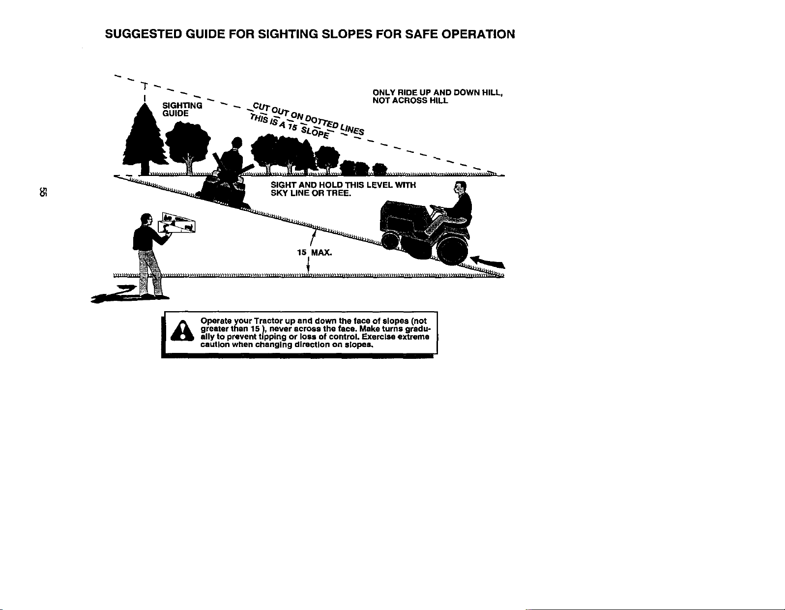
SUGGESTED GUIDE FOR SIGHTING SLOPES FOR SAFE OPERATION
SIGHTING _ _. CUT
GUIDE ;rH_.s
ONLY RIDE UP AND DOWN HILL,
NOT ACROSS HILL
I_k Operate your Tractor up and down the face of slopes (not
greater than 15 ), never across the face. Make turns gradu-
ally to prevent tipping or loss of control. Exercise extreme
caution when changing direction on slopes.

Forrepairofmajorbrandappliancesin yourown home...
nomatterwhomadeit,no matterwho_
1-800-4-MY-HOME @ An,/_e.dayorr_ll
0_0e-469_663) (u.sA_ Ca_da
WMP//JI_OIRLCOIlrt _P_WJieI1LC_
Forrepairofcarry-inproductslikevacuums,lawnequ_oment,and
electronics,callfor_ nearestSearsPartsand Repair Center.
1-800-488-1222 Any_e,dayorniglt(U.SAonly)
W_wJmtmLcorn
Forthereplacementparts,accessoriesandowner'smanuals
thatyou needb do-it-yourself,callSearsPartsDirectS'l
1-800-366-PART 6&m.-11 p.m., 7daysaweek
(1-8oo_7278) (u_._ or_)
_w_
To pumhaseorinquireabouta SearsSen_ceAgreement
orSeam MaintenanceAgreement
1-800-827-6655 (u.sJ_) 1-800-361-6665 (Canada)
7 aJ_ -5 pJ_ CST, Mo_- SaL 9aJ_ - 8pJn. EST,M- F,4 p.rrLSat
Parapecirsewi_ den_ a AuCanadapour_ enfran_ais:
don_io,yparao_enarpiezas: 1.8(X)4.E.FOYERMC
I_8-SU-HOGAR s_ (1_0-503_37)
_NW3eapsJ3a
® Registered Trademark / "tMTrademark / SMService Mark of Sears, Roebuck and Co.
® Marca Registrade I TM Mama de F&brica / sMMama de Servicio de Sears, Roebuck and Co.
MCMarque de commerce I MOMarque d_pos_e de Sears, Roebuck and Co.
179421 5.1.01 RD Printed in U.S.A,


