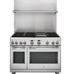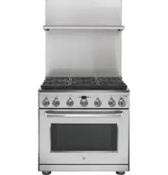
UXADJB36PSS, UXADJB48PSS
30” to 36” Adjustable Backsplash
WARNING
To prevent ignition of combustible
materials, the entire back wall above the range
must be protected by a backsplash constructed of
non-combustible material.
BEFORE YOU BEGIN
Read these instructions completely and carefully.
■ IMPORTANT — Save these instructions
for local inspector’s use.
■ IMPORTANT — Observe all governing
codes and ordinances.
■ IMPORTANT — Remove all packing
material and literature from oven before connecting
gas and electrical supply to range.
■ Note to Installer — Be sure to leave these
instructions with the consumer.
■ Note to Consumer — Keep these instructions with
your Owner’s Manual for future reference.
■ This backsplash adjusts to fit the space between the
top of the range and the bottom of the hood, from
30” Min. to 36” Max. height.
■ Maximum shelf load-bearing weight is 40 lbs.
Installation
Instructions
TOOLS AND MATERIALS REQUIRED
■Glovestoprotectagainstsharpedges
■T-15and#2Phillipsscrewdrivers
■Drillwith3/32”and9/64”bits
■Safetyglasses
■Level
■Pencil
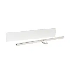
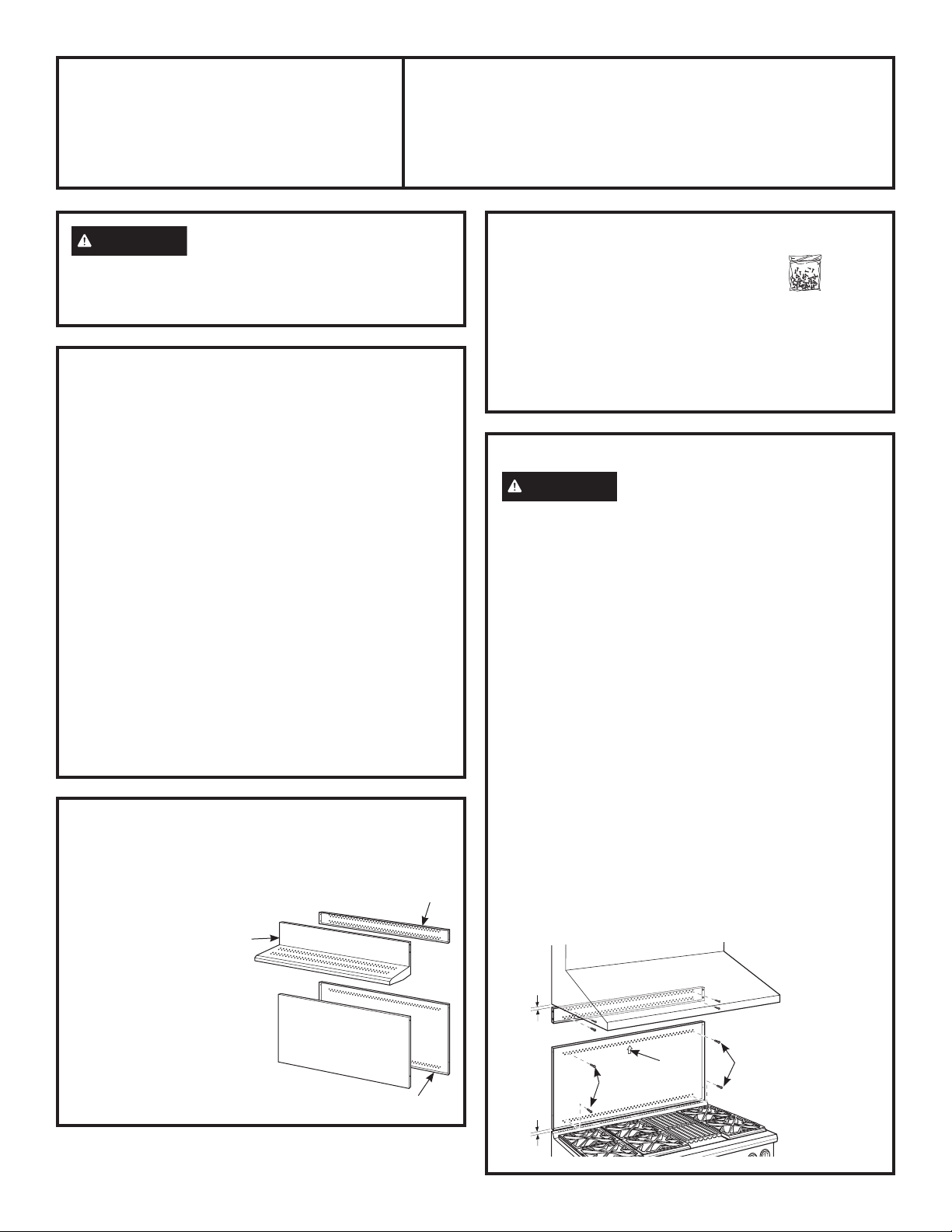
This Kit Includes
■Topwallsupport
■Bottomwallsupport
■Topcoverwithshelf
■Bottomcover
TOOLS AND MATERIALS REQUIRED
(Cont.)
■Hardwarepackagewith
–9StainlessSteelTorx15
#8self-tappingscrews
–9Phillips#2panheadwood#10screws
–3StainlessSteel#2trusshead#10screws(for
alternate installation method)
Hardware
Package
761Dia65
Top Cover
with Shelf
Bottom Cover
Bottom Wall Support
Top Wall
Support
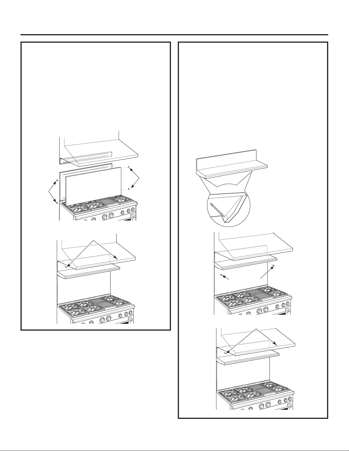
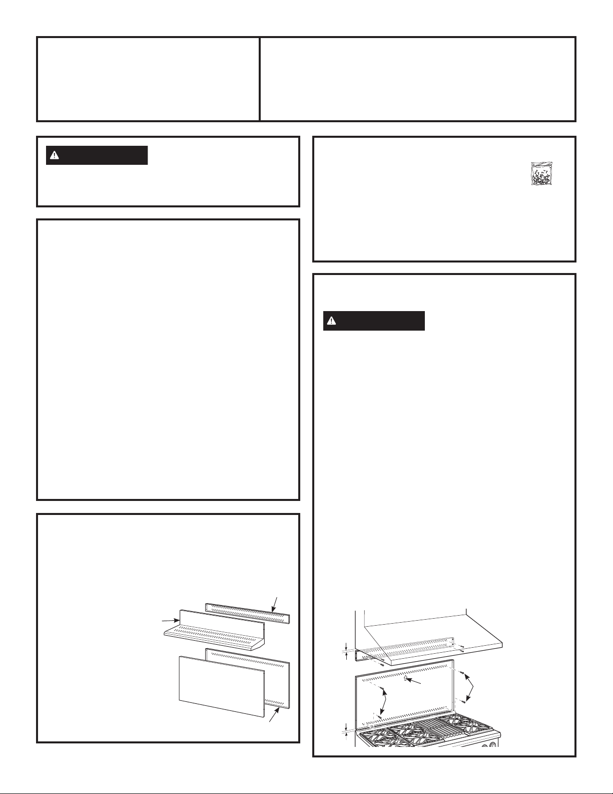
INSTALL THE WALL SUPPORT PANELS
WARNING
The wall support panels must be
securely fastened to the wall. Failure to do so could
result in damage or personal injury.
IMPORTANT: This backsplash is designed to cover
the wall between the bottom of the hood and the top of
the range. The vent hood should be installed over the
rangetop or range before installing this backsplash.
■InstallandleveltheRange/Rangetopaccordingto
the product installation instructions.
■Removebacksplashpackagingandprotectivefilm.
■Locatewallstudsoneachside.Wherestudsarenot
available,plantousewallanchors(notprovided).
■Usealeveltopencil2horizontallinesonthewall,
one1/8”belowtheventhoodandtheother1/8”
abovetheRange/Rangetop.This1/8”spaceallows
the cover panels to overlap the wall supports.
■Securethetopwallsupportpaneltothewallwith4
wood screws, through the outermost studs.
■Use4woodscrewstosecurethebottomwallsupport
panel. The center slot should be positioned at the top.
The gap between the top and bottom support panels
will be covered by the top cover with shelf.
1/8”
Secure the
top panel
to the wall
with 4 wood
screws
1/8”
Secure the
bottom panel
to the wall
with 4 wood
screws
Wood
Screws
Center
Arrow
Wood
Screws
31-10692-101-18GEA
2 31-10692-1
UXADJB36PSS, UXADJB48PSS Accessory Installation
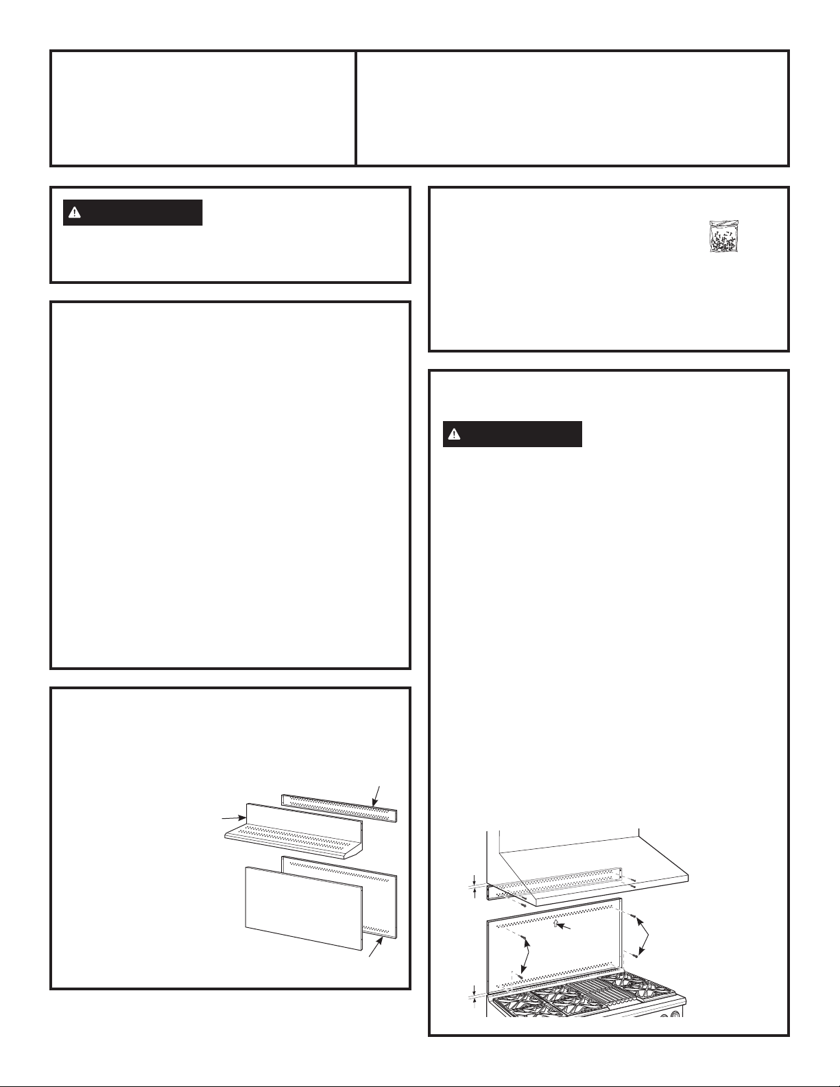
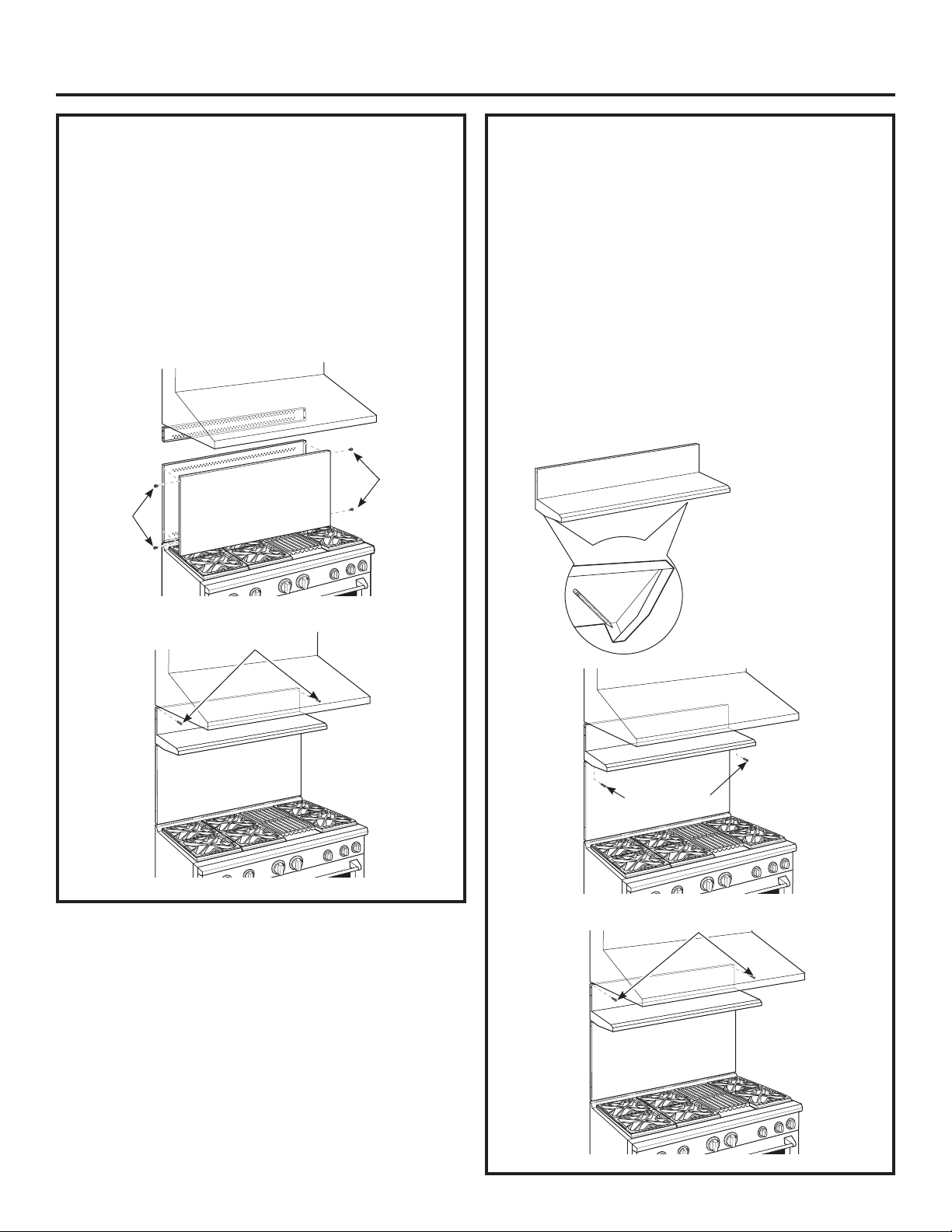
INSTALL COVER PANELS
See alternate method if side access is blocked.
■Holdthebottomcoveroverthebottomsupport
whiledrivingonescrew(provided)intoeachside.
■Placethetopcoverwithshelfoverthetopwall
support.Ifyouhaveaccesstothesides,securethe
panel with two screws on each side.
■Securethetopcoverwithshelftothetopsupport
with screws through the front of the panel, at the top
corners.Useonescrewoneachside.
INSTALL COVER PANELS (cont.)
ALTERNATE METHOD: When side access is blocked
■Installbottomcoveroverthebottomsupportwhile
driving one screw into each side.
■Holdtopcoverinplacewhilemarkingscrewlocations,
just below shelf support and onto bottom cover.
■Removetheshelfanddrilla9/64”diameterholein
the pencil-marked locations.
■Mountthetopcoveroverthetopsupportand
secure the front cover with screws through the
drilled holes on each side.
■Installscrewsthrougheachtopcorner.
Install
Screw
CoverPanel
Install
Screw
InstallCornerScrews
Mark Screw
Locationsfor
Alternate Method
InstallScrew
onEachSide
Shelf
InstallScrewinTopCorneronEachSide
31-10692-1 3
UXADJB36PSS, UXADJB48PSS
Dosseret ajustable 30” à 36”
AVERTISSEMENT
Afin d’éviter que les matériaux
inflammables ne prennent feu, la totalité de la surface du
mur se trouvant au-dessus de la cuisinière doit être protégée
par un dosseret ignifuge.
AVANT DE COMMENCER
Lisez attentivement l’ensemble des consignes.
■ IMPORTANT — Conservez ces instructions
pour l’inspecteur local.
■ IMPORTANT — Respectez toutes les normes
ainsi que les recommandations préconisées par les
autorités compétentes.
■ IMPORTANT — Retirez tout le matériel
d’emballage et la documentation dans le four avant de
raccorder les alimentationsen gaz et électrique à la cuisinière.
■ Remarque à l’attention de l’installateur — BAssurez-
vous de laisser ces instructions au consommateur.
■ Note au consommateur — Gardez ces instructions avec
votre manuel d’utilisation pour référence ultérieure.
■ Cedosseretestconçucomblerl’espaceentrelehaut
delacuisinièreetlebasdelahotte,entreunehauteur
maximale de 76 cm et 91 cm.
■ Lepoidsmaximaldeportancedel’étagèreestde18kg.
Instructions
d’installation
INSTALLEZ LES PANNEAUX DE
SUPPORT MURAL
AVERTISSEMENT
Lespanneauxdesupportmural
doivent être correctement fixés au mur afin d’éviter toute
blessure ou dommage matériel.
IMPORTANT :Cedosseretestconçupourcouvrirlemur
entre la partie supérieure de la cuisinière et la partie inférieure
delahotte.Lahotted’extractiondoitêtreinstalléesurlatable
de cuisson ou de la cuisinière avant d’installer le dosseret.
■ Installezetajustezlapositiondelatabledecuisson/
cuisinière conformément aux consignes d’installation.
■ Retirezl’emballagedudosseretetlefilmprotecteur.
■ Localisezlespoteauxmurauxsurchaquecôté.En
l’absencedepoteaux,utilisezplutôtdeschevillesmurales
(non fournies).
■ Utilisezunniveaupourtraceraucrayon2lignes
horizontalessurlemur,uneà1/8”souslahotte
d’extractionetl’autreà1/8”au-dessusdelatablede
caisson/cuisinière.Cetespacede1/8”faitquelepanneau
de recouvrement se superpose aux supports muraux.
■ Fixezlepanneaumuralsupérieuraumuràl’aidede4vis
à bois, à travers les poteaux externes.
■ Utilisez4visàboispourfixersupportmuralinférieur.La
rainurecentraledoitêtreplacéeenhaut.
L’espaceséparantlepanneaudesupportdubasdecelui
duhautseracombléparlaplaquesupérieuravecétagère.
OUTILS ET MATÉRIEL NÉCESSAIRES
■ Gantspourvousprotégerdespartiestranchantes
■ Tourneviscruciforme2etT-15
■ Percezavecdesforets23mm
(3/32”)et35mm(9/64”)
■ Lunettesprotectrices
■ Niveau
■ Crayon
Ce Kit comprend
■ Panneaudesupportmural
■ Panneaumurinférieur
■ Panneausupérieur
avec étagére
■ Plaqueinférieure
OUTILS ET MATÉRIEL NÉCESSAIRES
(suite)
■ Sachetdematérielcontenant
– 9 vis autotaraudeuses à 6 lobes
internesenacierinoxydable15,no8
–9visàtêtecylindriquebombéeno2pourboisno10
–3visàtêtebombéeno2enacierinoxydableno10
(pouruneméthoded’installationalternative)
Panneau
supérieur
avec étagère
Plaqueinférieure
Supportmuralinférieure
Supportmural
supérieur
Sachet
de matériel
761Dia65
31 mm
(1/8”)
31 mm
(1/8”)
Vis à
bois
Flèche
centrale
Vis à
bois
Fixezle
panneau
supérieur au
muravec4
vis à bois
Fixezle
panneau
inférieur au
muravec4
vis à bois
4 31-10692-1
UXADJB36PSS, UXADJB48PSS Installation d’accessoires
INSTALLEZ LES PANNEAUX DE
RECOUVREMENT
Optezpourlaméthodealternativesil’accèslatéralestbloqué.
■ Maintenezlaplaqueinférieuresurlesupporttouten
vissantunevis(fournie)dechaquecôté.
■ Placezlaplaquesupérieureavecl’étagèreenplacesurle
supportmuralsupérieur.Sivouspouvezaccéderauxdeux
côtés,fixezlepanneauavecdeuxvissurchaquecôté.
■ Fixezlaplaquesupérieureavecl’étagèresurlesupport
supérieur et fixez la plaque à l’aide de vis sur l’avant du
panneau,surlescoinssupérieurs.Utilisezunevisparcôté.
INSTALLEZ LES PANNEAUX DE
RECOUVREMENT (suite)
MÉTHODE ALTERNATIVE : En cas d’obstruction de
l’accès latéral
■ Installezlaplaqueinférieuresurlesupportinférieurtout
envissantunevisdechaquecôté.
■ Maintenezlaplaquesupérieureenplacetouten
marquantlesemplacementsdesvis,justeendessousde
l’étagère de support et sur la plaque inférieure.
■ Retirezl’étagèreetpercezuntroude0,35cm(9/64”)de
diamètredanslesemplacementstracésaucrayon.
■ Montezlaplaquesupérieuresurlesupportsupérieuret
fixez la plaque à l’aide de vis dans les trous percés sur
chaquecôté.
■ Installezlesvisàtraverschaquecoinsupérieur.
Installez
une vis
Panneaude
recouvrement
Installez
une vis
Installezlesvispourlescoins
Marquezles
emplacements
des vis pour
l’autreméthode
Installezlavissur
chaquecôté
Étagère
Installezlavissurlecoinsupérieurdechaquecôté
31-10692-1 5
ANTES DE COMENZAR
Lea estas instrucciones por completo y con detenimiento.
■ IMPORTANTE — Conserve estas
instrucciones para uso del inspector de electricidad local.
■ IMPORTANTE — Cumpla con todos los
códigos y ordenanzas gubernamentales.
■ IMPORTANTE — Retire todo el material de
embalaje y material escrito del horno antes de conectar el
gas y el suministro de corriente a la cocina.
■ Nota para el Instalador — Asegúrese de que estas
instrucciones queden en manos del comprador.
■ Nota para el Consumidor — Guarde estas instrucciones
para referencia futura.
■ Este salpicadero puede ajustarse para poder utilizarse en
el espacio entre la parte superior de la cocina y la parte
inferior de la capucha, con una altura mínima de 30” y
una máxima de 36”.
■ El peso máximo de capacidad de carga del estante es
de 40 lbs.
UXADJB36PSS, UXADJB48PSS
Salpicadero ajustable de 30” a 36”
ADVERTENCIA
Para prevenir el encendido de
materiales combustibles, debe protegerse toda la pared
trasera de la cocina mediante un salpicadero construido con
un material no combustible.
Instrucciones
de instalación
INSTALE LOS PANELES DE SOPORTE
DE PARED
ADVERTENCIA
Los paneles de soporte de pared
deben estar bien sujetos a la pared. No hacerlo puede
provocar daños o lesiones personales.
IMPORTANTE: Este salpicadero se encuentra diseñado para
cubrir la pared entre la parte inferior de la capucha y la parte
superior de la cocina. La capucha de ventilación debe instalarse
sobre la estufa o cocina antes de instalar el salpicadero.
■ Instaleynivelelacocina/estufadeacuerdoconlas
instrucciones de instalación del producto.
■ Quiteelempaqueylapelículaprotectoradelsalpicadero.
■ Ubiquelosparantesenamboslados.Dondenohaya
parantes disponibles, utilice anclajes de pared (no provistos).
■ Utiliceunnivelparamarcarconlápiz2líneas
horizontalessobrelapared,una1/8”pordebajodela
capuchadeventilaciónylaotra1/8”porencimadela
cocina/estufa.Elespaciode1/8”permitequelospaneles
de cubierta se superpongan con los soportes de pared.
■ Fijeelpaneldesoportedeparedsuperioralaparedcon4
tornillos para madera, a través de los parantes exteriores.
■ Utilice4tornillosparamaderaparafijarelpanelde
soporte de pared inferior. La ranura central debe ubicarse
en la parte superior.
El espacio entre los paneles de soporte superior e inferior
se cubrirá con la cubierta superior con estante.
1/8”
1/8”
Tornillos
para
madera
Flecha
central
Tornillos
para
madera
Fijeelpanel
superior a la
pared con 4
tornillos para
madera
Fijeelpanel
inferior a la
pared con
4 tornillos
para madera
HERRAMIENTAS Y MATERIALES
REQUERIDOS
■ Guantesparaprotegersedebordesfilosos
■ DestornilladoresT-15ydeestrella#2
■ Perforadoraeléctricaconmechas
de3/32”y9/64”
■ Gafasdeseguridad
■ Nivel
■ Lápiz
Este kit incluye
■ Soportedeparedsuperior
■ Soportedeparedinferior
■ Cubiertasuperiorconestante
■ Cubiertainferior
HERRAMIENTAS Y MATERIALES
REQUERIDOS (Cont.)
■ Paquetedeferreteríacon
–9tornillosauto-roscantes#8Torx15de
acero inoxidable
–9tornillosdeestrella#2paramaderadecabeza
troncocónica#10
–3tornillosdecabezasegmentada#10deacero
inoxidable#2(paraunmétododeinstalaciónalternativo)
Cubierta
superior con
estante
Cubierta inferior
Soportedeparedinferior
Soportede
pared superior
Paquete de
ferretería
761Dia65

6 31-10692-1
Instalación de accesorios UXADJB36PSS, UXADJB48PSS
INSTALE LOS PANELES DE CUBIERTA
Ver el método alternativo si el acceso lateral se encuentra
bloqueado.
■ Sostengalacubiertainferiorsobreelsoporteinferior
mientras coloca un tornillo (provisto) sobre cada lado.
■ Coloquelacubiertasuperiorconestantesobreelsoporte
deparedsuperior.Sitieneaccesoaloslados,fijeel
panel con dos tornillos de cada lado.
■ Fijelacubiertasuperiorconestantealsoportesuperior
con tornillos a través de la parte frontal del panel, en las
esquinassuperiores.Utiliceuntornilloencadalado.
INSTALE LOS PANELES DE CUBIERTA
(cont.)
MÉTODO ALTERNATIVO: Cuando el acceso lateral se
encuentra bloqueado.
■ Instalelacubiertainferiorsobreelsoporteinferior
mientras coloca un tornillo sobre cada lado.
■ Sostengalacubiertasuperiorensulugarmientras
marca las ubicaciones de los tornillos, apenas debajo del
soporte de estante y sobre la cubierta inferior.
■ Quiteelestanteyperforeunorificiode9/64”dediámetro
en las ubicaciones marcadas con lápiz.
■ Montelacubiertasuperiorsobreelsoportesuperioryfije
la cubierta frontal con tornillos a través de los orificios
perforados sobre cada lado.
■ Instaletornillosatravésdecadaesquinasuperior.
Instale
el tornillo
Panel de
cubierta
Instale
el tornillo
Instaletornillosenlasesquinas
Marquelas
ubicaciones de
tornillos para el
método alternativo
Instaleuntornillo
en cada lado
Estante
Instaleuntornilloenlaesquinasuperiordecadalado

31-10692-1 7
Notes

8 31-10692-1
PrintedinMexico•ImpriméauMexique•ImpresoenMéxico
NOTE: While performing installations described in this book,
safety glasses or goggles should be worn.
NOTE: Product improvement is a continuing endeavor.
Therefore, materials, appearance and specifications are
subject to change without notice.
REMARQUE : lorsque vous procédez aux installations
abordées dans ce manuel, il est fortement recommandé de
porter des lunettes de sécurité.
REMARQUE : la philosophie fait la part belle à l’innovation.
C’est pourquoi les matériaux, les caractéristiques et
l’apparence extérieure peuvent faire l’objet de modifications
sans préavis.
NOTA: Mientrasefectúalasinstalacionesdescriptaseneste
libro, deben utilizarse gafas o lentes de seguridad.
NOTA: La mejora de los productos es un esfuerzo
continuo. Por lo tanto, los materiales, la apariencia y las
especificaciones pueden sufrir cambios sin previo aviso.